Consultant Contract #YX-XXX Engineering Services Proposal For Gravity R/R Package X Wastewater...
52
Consultant Contract #YX-XXX Engineering Services Proposal For Gravity R/R Package X Wastewater Improvements SA number (name of subdivision) SA number (name of subdivision) SA number (name of subdivision) SA number (name of subdivision) SA number (name of subdivision) Pump Station R/R Package X Improvements PS number (name of pump station) PS number (name of pump station) PS number (name of pump station) PS number (name of pump station) PS number (name of pump station) Project Purpose The Gravity R/R Program for the next 5 years is addressing all of the 306 miles of vitrified clay pipe. We have grouped VCP gravity service subareas into final design and construction packages. The Gravity R/R Program has developed a database for gravity CCTV inspection, condition assessment, and recommendations for the R/R work. A data computer software program has been developed to manage the data and evaluate the defects observed to assist in condition assessment and recommendations for the R/R work. We are able to plot from the database, which is accessible from GIS, graphic maps and tables of the R/R work to be done. These plots become our design drawings for the lining of gravity mains. These drawings are included in the construction documents with the Engineer’s documents for the replacement of the gravity mains, the manholes, and the laterals that need R/R work. Page 1 of 52 OCU Engineer Proposal Template rev. May 2013
-
Upload
independent -
Category
Documents
-
view
1 -
download
0
Transcript of Consultant Contract #YX-XXX Engineering Services Proposal For Gravity R/R Package X Wastewater...
Consultant Contract #YX-XXX
Engineering Services Proposal For
Gravity R/R Package X Wastewater Improvements SA number (name of subdivision) SA number (name of subdivision)SA number (name of subdivision)SA number (name of subdivision)SA number (name of subdivision)
Pump Station R/R Package X ImprovementsPS number (name of pump station) PS number (name of pump station)PS number (name of pump station) PS number (name of pump station) PS number (name of pump station)
Project Purpose
The Gravity R/R Program for the next 5 years is addressing all ofthe 306 miles of vitrified clay pipe. We have grouped VCPgravity service subareas into final design and constructionpackages. The Gravity R/R Program has developed a database forgravity CCTV inspection, condition assessment, andrecommendations for the R/R work. A data computer softwareprogram has been developed to manage the data and evaluate thedefects observed to assist in condition assessment andrecommendations for the R/R work. We are able to plot from thedatabase, which is accessible from GIS, graphic maps and tablesof the R/R work to be done. These plots become our designdrawings for the lining of gravity mains. These drawings areincluded in the construction documents with the Engineer’sdocuments for the replacement of the gravity mains, the manholes,and the laterals that need R/R work.
Page 1 of 52
OCU Engineer Proposal Template rev. May 2013
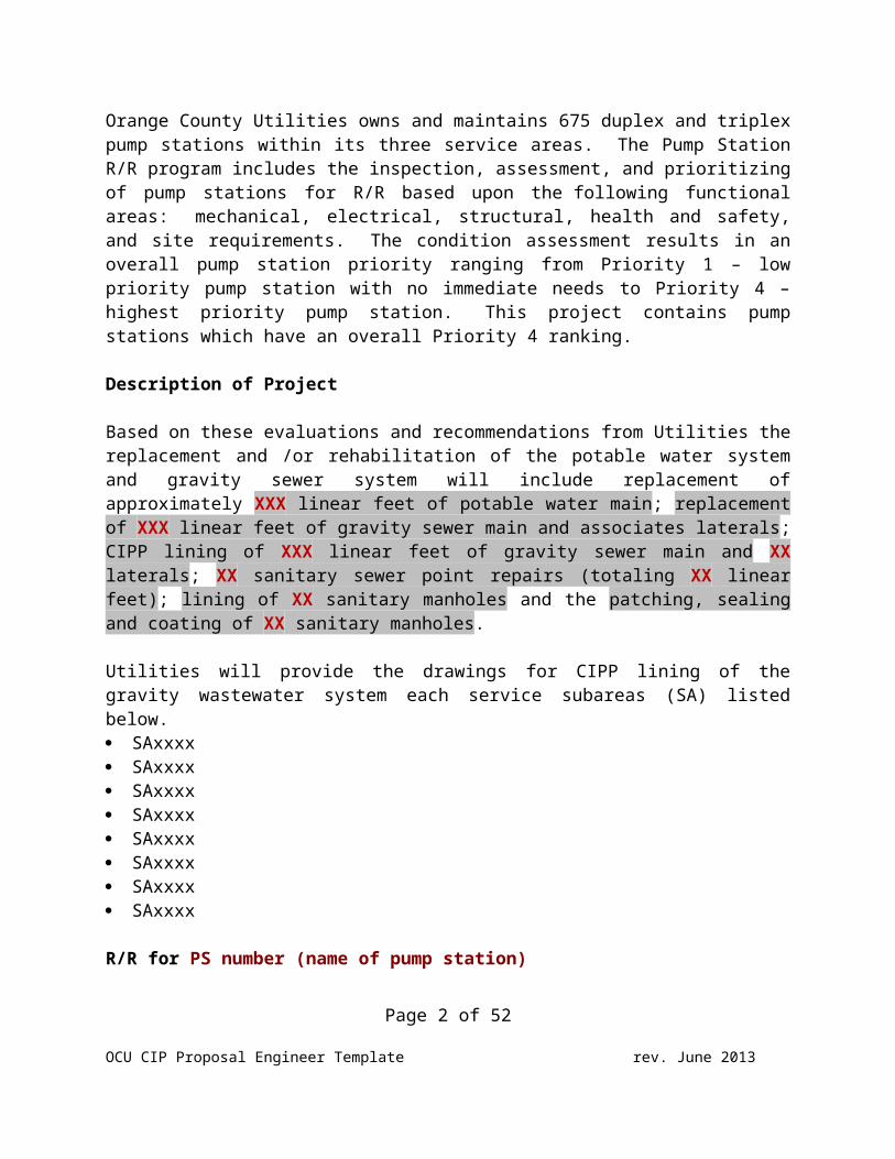
Orange County Utilities owns and maintains 675 duplex and triplexpump stations within its three service areas. The Pump StationR/R program includes the inspection, assessment, and prioritizingof pump stations for R/R based upon the following functionalareas: mechanical, electrical, structural, health and safety,and site requirements. The condition assessment results in anoverall pump station priority ranging from Priority 1 – lowpriority pump station with no immediate needs to Priority 4 –highest priority pump station. This project contains pumpstations which have an overall Priority 4 ranking.
Description of Project
Based on these evaluations and recommendations from Utilities thereplacement and /or rehabilitation of the potable water systemand gravity sewer system will include replacement ofapproximately XXX linear feet of potable water main; replacementof XXX linear feet of gravity sewer main and associates laterals;CIPP lining of XXX linear feet of gravity sewer main and XXlaterals; XX sanitary sewer point repairs (totaling XX linearfeet); lining of XX sanitary manholes and the patching, sealingand coating of XX sanitary manholes.
Utilities will provide the drawings for CIPP lining of thegravity wastewater system each service subareas (SA) listedbelow. SAxxxx SAxxxx SAxxxx SAxxxx SAxxxx SAxxxx SAxxxx SAxxxx
R/R for PS number (name of pump station)
Page 2 of 52
OCU CIP Proposal Engineer Template rev. June 2013
The renewal work is based on the recommendations provided on thesummary report dated month day, 2013 and the report is includedas Attachment 1. The pump station is located at “address” andcan be improved in place. The improvements are generallydescribed as follows: Convert of pump station wetwell to a manhole and remove the
existing valve vault Replace a portion of 8” gravity main Construct a new pump station Replace a portion of the existing force main Line the existing wetwell Replace the access hatches Replace the existing pumps Replace the existing riser pipes Replace valve vault with above grade piping Replace valve vault piping and valves New emergency pump out Relocate control panel and SCADA system New concrete access drive New CMU wall with anti-graffiti paint Replace access gate New odor control unit New generator and associated fuel storage tank Replace the electrical control panel and SCADA system
NOTE: The projects as described separately above, will be included together in one set of construction documents and be bid and constructed together.
The appended Exhibit C includes the following. Preliminary Engineering Construction Cost Estimate Table 1 Water Distribution System Improvements Table 2 Gravity System Improvements GIS Map Delineation
o water main replacement locationso topographic survey limitso GPR cross sections with VVHso groundwater sampling locations
Utilities Sample R/R Schematic Drawing for CIPP LiningPage 3 of 52
OCU CIP Proposal Engineer Template rev. June 2013
FDEP OCULUS Contamination Location Map and Descriptions
The professional services that will be performed bysubconsultants are as follows: Computer Aided Drafting Services: QA/QC and Constructability Review of Final Design phases: Surveying Services:
o Subtasks Geotechnical Investigations: Groundwater Sampling/Testing:
o Lab Analysis: Ecological Investigations: Construction Administration Services:
Scope of WorkEngineering services shall provide design drawings andspecifications that meet or exceed the requirements of Utilities’Standards and Construction Specifications Manual (Manual),utilize Utilities Master CIP Technical Specifications, andstandard drawing templates for the construction of water mains,force mains, reclaimed water mains, gravity system, and pumpstations,. The Engineer is responsible for all work of theirsubconsultants/subcontractors to meet the requirements of the Engineer’s proposal.The County requires the subconsultant/subcontractor proposals to be attached to theEngineer’s proposal. The following tasks will be performed as part ofthe work:
Task 100 Preliminary Engineering: (SA # or PS #) Task 200 Construction Documents: (SA # or PS #) Task 300 Surveying: (SA # or PS #) Task 400 Geotechnical Investigation and Groundwater
Sampling and Testing: (SA # or PS #) Task 500 Ecological Investigation: (SA # or PS #) Task 600 Public Relations: Community Meeting/Public
Notification-Flier Production and Mailing Procedure: (SA #or PS #)
Task 700 Bidding Assistance Task 800 Construction Administration Services
Page 4 of 52
OCU CIP Proposal Engineer Template rev. June 2013
TASK 100 - PRELIMINARY ENGINEERING
The purpose of the preliminary engineering phase is to presentproject completion alternatives to Utilities in a manner thatwill allow Utilities to make an informed decision as to how theproject shall proceed. Minimal survey services will be performedduring the Preliminary Engineering unless approved by theUtilities Project Manager.
Subtask 110 Data Collection1. Coordinate and attend Kick-off meeting. Prepare and
distribute meeting minutes.2. Collect and review all available information such as
records, maps, aerials, surveys, easements, ROW records,zoning classifications, plans, record drawings, soilsinvestigation reports, building codes and standards that maybe pertinent to execution of the Project. Review allrequirements of all agencies having jurisdiction over theProject. Collect and review any other information that mayhave a bearing and impact on the planning, design, approval,permitting, construction or operation of the Project.
3. Review any previous inspection and condition assessmentreports and recommendations prepared by Utilities.
4. Coordinate with Utilities any inspection and testing workof the gravity sewer one (1) manhole upstream outside the pumpstation. Inspection work to be performed by Utilities staffshall include televising the gravity main, manholeinspections, one week of VoluCalc pump station flow data, andif available, pump station draw down test data.
5. Evaluate existing conditions along the proposed pipeinstallation route by site visitation. Consider current fieldconditions and any proposed site improvements and/or changesthat may impact the project and recommended location of theproposed pipeline.
Subtask 120 Preliminary Engineering ReportAs a minimum the Engineer shall provide the following:
Page 5 of 52
OCU CIP Proposal Engineer Template rev. June 2013
1. For each pump station, Utilities will estimate thewastewater flows based upon Utilities’ hydraulic model, oneweek of VoluCalc data from each pump station, and providesystem curves for use by the Engineer. Engineer will performthe following duties: Estimate the capacity of the influent gravity lines based
on the Manning Equation, appropriate Orange CountyStandards, and generally accepted engineering practice.Also, Engineer will consider the wet well storage volumes,appropriate Orange County Standards, and generally acceptedengineering practice to ascertain the ability of the wetwells to accommodate the design flows. Subsequently,Engineer will document the capacity and operationalconditions for each pump station, provide pump selectionsfor both Flygt and ABS pumps.
Develop a preliminary site and yard piping plan for eachpump station.
The submitted bound preliminary design report shallcomprise the following contents: Section 1 IntroductionSection 2 Capacity requirements (discuss data supplied by
Utilities and Engineer’s recommendation)Section 3 Condition Assessment (prepare an itemized
list of Utilities condition assessments, StandardsManual requirements, and Engineer observations foreach pump station).
Section 4 Gravity condition assessment (Anycollection/transmission system improvementsassociated with the pumping stations)
Section 5 Permit requirementsSection 6 Opinion of Probable Construction Cost (Use
the Utilities’ schedule of values for the pumpstations).
Section 7 Recommendations (include preliminary site andyard piping plan)
Appendix A Photographs Appendix B Design calculations (Pump calculations,
working volume calculations for run-starts perPage 6 of 52
OCU CIP Proposal Engineer Template rev. June 2013
hour, pump impeller selection, capacity ofincoming gravity main, and force main calculationsif the force main flows into gravity).
Appendix C Surveys (Boundary and Topographic Survey andBoundary Survey)
Appendix D Information provided by Utilities ConditionAssessment, system curves, VoluCalc data, and CCTVrecommendations made for the gravity system.
2. Documentation of the proposed water main and forcemainimprovements. The preliminary design report shall comprise the following
contents:Section 1 Introduction (general design criteria)Section 2 Observations (sequence of work, MOT, new
pavement resurfacing, existing utilities, fencesin right-of-way, etc.)
Section 3 A table tabulation of water mains to bereplaced based upon adequate water pressure forfire flow and the quantities of cement asbestospipe with their respective sizes to remain
Section 4 Photographs of street (potential alignmentconflicts with trees, etc.)
Section 5 Permit requirementsSection 6 Opinion of Probable Construction Cost (Use
Utilities’ measurement and payment items).Section 7 Recommendations (include pipe alignment
schematic map and indicate all major conflictswith existing utilities and all areas wherespecial construction techniques must beconsidered. Additionally, present any otherpertinent information necessary for Utilities toevaluate the proposed alignment)
Appendix A Design calculations
Deliverables:1. Preliminary Design Report will include tabs for each of the
sections and appendices
Page 7 of 52
OCU CIP Proposal Engineer Template rev. June 2013
2. Submit six (6) copies of the draft “Preliminary DesignReport” to Utilities. Meet with Utilities to discuss andrevise in accordance with the comments from Utilities. Submittwo (2) hard copies and a digital copy as a single PDF of thefinal “Preliminary Design Report”.
3. A separate PDF digital copy of the Pump Station PDR portionafter the PDR has been approved. The Pump Station PDR will bedownloaded into the Pump Station R/R Program database.
TASK 200 - CONSTRUCTION DOCUMENTS
The construction documents shall be complete and meet allrequirements for construction contract competitive bidformulation and subsequent construction of the Project. Alldocuments shall comply with the current requirements of theOrange County Utilities Standards and Construction SpecificationsManual, Attachment 2 Drawing File Naming Conventions, and therequirements as described in this proposal. Provide qualityassurance and "constructability" review prior to all submittalsto Utilities. Design services will include 60%, 90%, and 100%document submittals, survey, geotechnical, ecologicalinvestigation, and permitting. The Engineer has estimated insert# single plan and profile drawings for water and force mainreplacement drawings at a scale of 1”= 20’ horizontal and 1”= 4’vertical, insert # schematic gravity main R/R improvementdrawings at a scale of 1”=200’, and insert # GIS aerial plandrawings for gravity main point repairs and manhole replacementat a scale of 1”=20’, and insert # general information and detaildrawings. The Engineer shall confirm with the Utilities ProjectManager (PM) the ground penetrating cross sectional areas to beinvestigated at Utility Quality Level A prior to any survey workperformed.
Subtask 210 – 60% Level of CompletionShall be defined as a complete set (all sheets that will be inthe bid package) of plan and profile drawings indicating allsurvey and topographic information, depiction of all subsurface
Page 8 of 52
OCU CIP Proposal Engineer Template rev. June 2013
utility data in accordance with CI/ASCE 38-02, ASCE StandardGuideline for the Collection and Depiction of Existing SubsurfaceUtility Data, all utility connections, Standard Drawing DetailChecklist and proposed drawing details, Utilities Master CIPTechnical Specifications checklist, specific technicalspecification sections with proposed changes, any proposed newpay items, and Engineer’s Estimate of Probable Cost utilizingUtilities Standard Pay Items. If in the opinion of the PM the60% level of completion is not met, the submittal shall beresubmitted with the appropriate missing information.
General Requirements1. If ground water sample results of the water analysis
exceed the allowable levels of the specified water qualityparameters (see Table 2, Screening Values for Discharge ofProduced Ground Water), the Engineer shall provide remedy(s)in the Utilities Master CIP Technical Specifications Section02140, Dewatering, paragraph 3.03.
2. All existing utilities shall be shown on the plans inaccordance with the CI/ASCE 38-02, ASCE Standard Guideline forthe Collection and Depiction of Existing Subsurface UtilityData. Existing utilities shall be identified with a utilityquality level by an appropriate abbreviation and legend. Inaddition, place on the drawings: the note found below, indexnotes, legend and abbreviations, and a horizontal and verticaldata table in accordance with CI/ASCE 38-02 Utility QualityLevel Information Index on the plan and profile drawings.
NOTE: This drawing was prepared in conformancewith ASCE standard CE/ASCE 38-02” American Societyof Civil Engineers Standard Guideline for theCollection and Depiction of Existing SubsurfaceUtility Data”.
3. A physical walk-through of the proposed pipe(s)route shall be made by the Orange County Utilitiesconstruction inspector, PM, and the Engineer prior to the 60%review meeting.
4. Drawings shall use the Utilities drawing namingconvention shown in Attachment 2 of this proposal.
Page 9 of 52
OCU CIP Proposal Engineer Template rev. June 2013
5. Any modifications to the OCU Standards andConstruction Specification Manual’s Standard Drawings shall benoted.
6. Meet with Utilities to discuss the 60% submittal,prepare a written list of Utilities comments, submit toUtilities for verification and subsequently revise theconstruction documents per Utilities’ comments.
7. Coordinate with the Orange County Public Works Department(Public Works). Submit one (1) printed set of 60% constructiondrawings as a separate submittal package with cover letter forreview and comment to each: A. Manager of Development Engineering Division B. Manager of Highway Construction Division C. Manager of Stormwater Management DivisionD. Manager of Public Works Engineering Division E. Manager of Traffic Engineering DivisionF. Manager of Roads and Drainage DivisionG. Manager of Transportation Planning Division
8. Incorporate Public Works comments into thedrawings and specifications after approval by the PM. Anemail shall be submitted by the Engineer verifying whethereach of the preceding Public Works Divisions have reviewed andcommented on the drawings.
Deliverables:1. Submit all Survey deliverables.2. Submit seven (7) printed sets of the 60% design drawings.
A. All required plan and profile drawingsB. Design packages from Utilities C. AutoCAD drawings for title sheet, general notes and
detailsD. All AutoCAD drawings for the renewal and/or
replacement of pump stations3. Complete the Utilities Master CIP Technical Specification
Checklist.4. Any Master CIP Technical Specifications with proposed
tracked changes.5. Complete the Utilities Standard Drawing Detail Check List
Page 10 of 52
OCU CIP Proposal Engineer Template rev. June 2013
6. Any proposed Drawing Detail(s)7. Provide the Engineer’s Estimate of Probable Cost utilizing
Utilities Standard Pay Items.8. Any proposed new pay items shall be submitted with
measurement and payment description to match Utilities formatand numbered with an appropriate payment item sequence.
9. Submit a paper copy of the Geotechnical InvestigationReport to Utilities and a digital CD copy in MS Word format.
10. Submit a paper copy of the Ecological Investigation Reportto Utilities and a digital CD copy in MS Word format.
Subtask 220 - 90% Level of CompletionShall be defined as a complete set the construction drawings andspecifications containing all of the general and precedingrequirements that would allow the Project to be bid, Utilities’60% review comment tabulation (Excel spreadsheet), and 60% reviewcomments were addressed, and an opinion of the probableconstruction cost utilizing Utilities Standard Pay Items. If inthe opinion of the PM the 90% level of completion is not met, thesubmittal shall be resubmitted with the appropriate missinginformation.
General Requirements:1. The Engineer shall indicate fittings on the construction
plans for pipe deflections. PVC pipe shall be designed withno pipe deflections and shall have fittings for all bends.
2. An electronic blank file of the Record Drawing AssetAttribute Data Table in Excel format will be provided byUtilities to the Engineer upon request.
3. The As-built Asset Attribute Data Table worksheets shall be shown in the construction drawings and placed as the lastsheets of drawings. Identify all assets on the drawings witha unique numbering procedure. Utility assets andinfrastructural features shall be labeled on the drawings withunique identification numbers in order to create a linkbetween the drawings and the As-Built Asset Attribute DataTable. The unique numbers with asset descriptions are to befilled in on the latest Utilities As-built Asset Attribute
Page 11 of 52
OCU CIP Proposal Engineer Template rev. June 2013
Data Table in the appropriate worksheet. The worksheets shallinclude all of the Utilities’ pertinent assets listed in Table1 Minimum Survey Accuracies per Asset (proposed and existingWater, Wastewater, and Reclaimed Water). All of the County’smanhole asset numbers will be used.
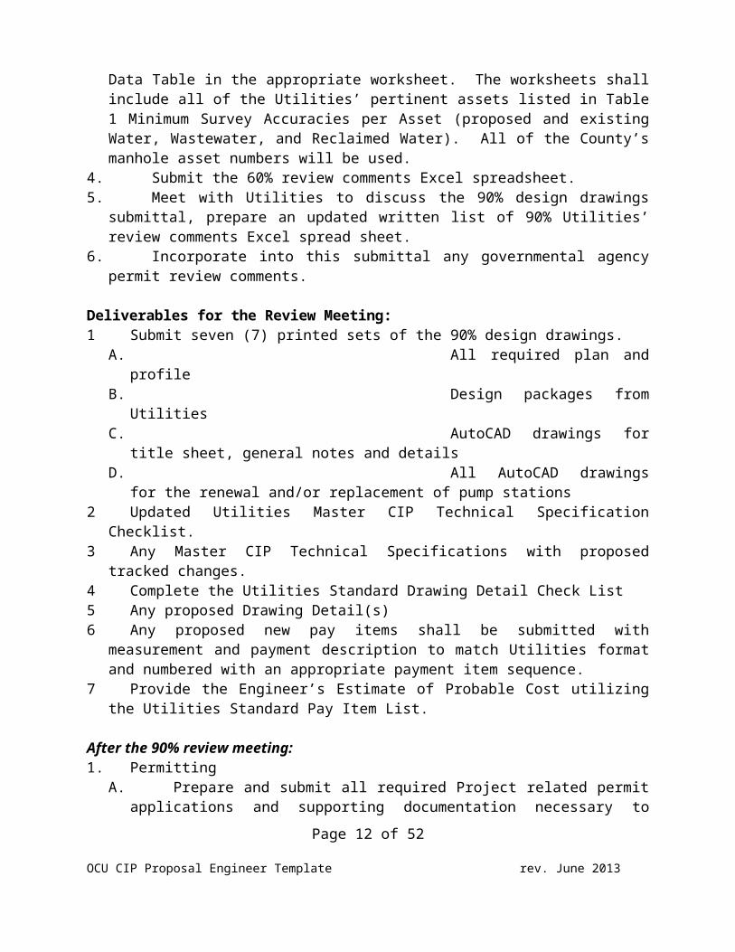
4. Submit the 60% review comments Excel spreadsheet.5. Meet with Utilities to discuss the 90% design drawings
submittal, prepare an updated written list of 90% Utilities’review comments Excel spread sheet.
6. Incorporate into this submittal any governmental agencypermit review comments.
Deliverables for the Review Meeting:1 Submit seven (7) printed sets of the 90% design drawings.
A. All required plan andprofile
B. Design packages fromUtilities
C. AutoCAD drawings fortitle sheet, general notes and details
D. All AutoCAD drawingsfor the renewal and/or replacement of pump stations
2 Updated Utilities Master CIP Technical SpecificationChecklist.
3 Any Master CIP Technical Specifications with proposedtracked changes.
4 Complete the Utilities Standard Drawing Detail Check List5 Any proposed Drawing Detail(s)6 Any proposed new pay items shall be submitted with
measurement and payment description to match Utilities formatand numbered with an appropriate payment item sequence.
7 Provide the Engineer’s Estimate of Probable Cost utilizingthe Utilities Standard Pay Item List.
After the 90% review meeting:1. Permitting
A. Prepare and submit all required Project related permitapplications and supporting documentation necessary to
Page 12 of 52
OCU CIP Proposal Engineer Template rev. June 2013
obtain required permits for construction and operation ofthe Project from all applicable agencies (Florida Departmentof Environmental Protection, Florida Department ofTransportation, County Public Works and BuildingDepartments, Water Management Districts, Railroad, etc.)with jurisdiction over the Project.
B. Respond to all requests for additional information frompermitting agencies.
C. Submit all acquired permits.2. All permit fees are included in the engineering fee
compensation. Utilities will reimburse permit fees paid by theEngineer.
3. Red-line a set of plans and spreadsheet for Utilities 90%review comments. Red-line and flag each page of thespecification showing Utilities’ 90% review comments. Do notmake changes to the project documents until after theUtilities Design Review Group (DRG) has performed a finalreview. Final review comments will be transmitted by the PM tothe Engineer.
Page 13 of 52
OCU CIP Proposal Engineer Template rev. June 2013
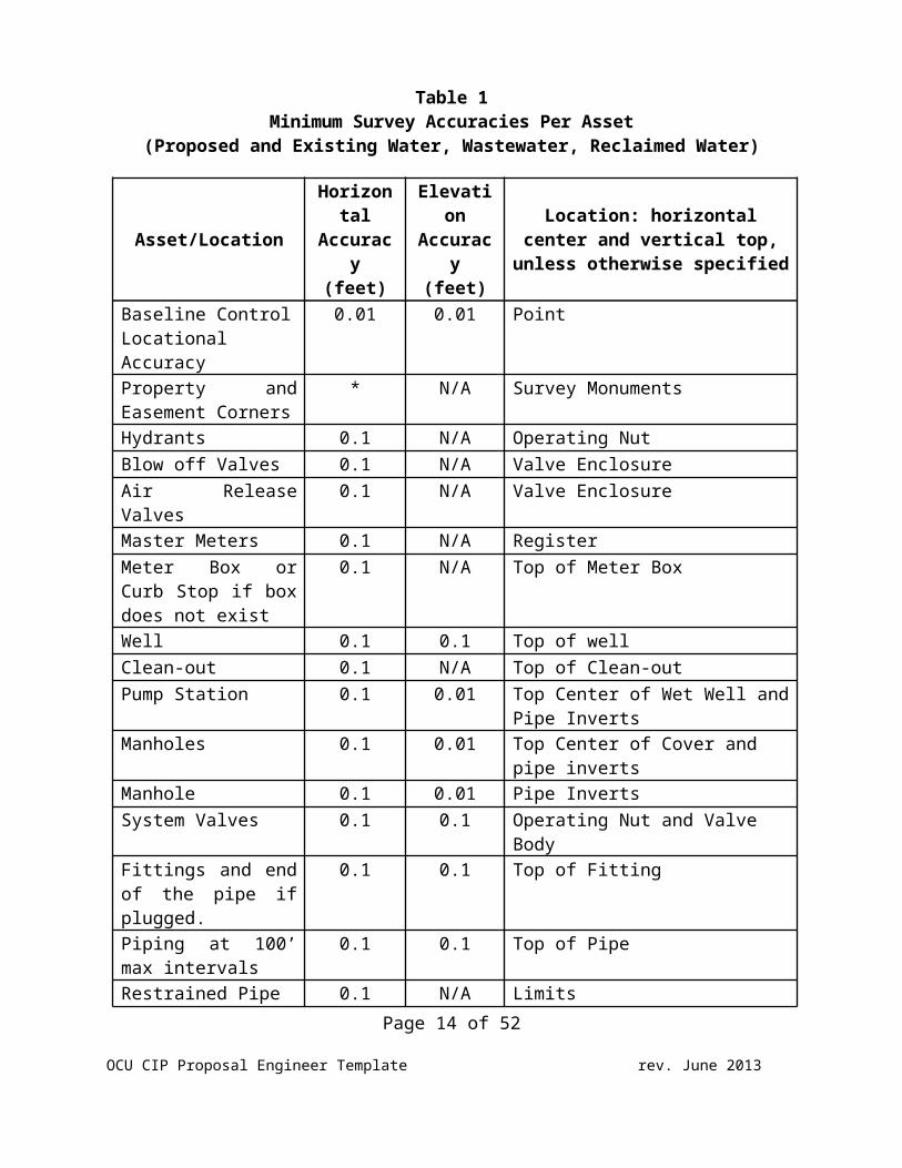
Table 1Minimum Survey Accuracies Per Asset
(Proposed and Existing Water, Wastewater, Reclaimed Water)
Asset/Location
Horizontal
Accuracy
(feet)
Elevation
Accuracy
(feet)
Location: horizontalcenter and vertical top,
unless otherwise specified
Baseline ControlLocational Accuracy
0.01 0.01 Point
Property andEasement Corners
* N/A Survey Monuments
Hydrants 0.1 N/A Operating NutBlow off Valves 0.1 N/A Valve EnclosureAir ReleaseValves
0.1 N/A Valve Enclosure
Master Meters 0.1 N/A RegisterMeter Box orCurb Stop if boxdoes not exist
0.1 N/A Top of Meter Box
Well 0.1 0.1 Top of wellClean-out 0.1 N/A Top of Clean-outPump Station 0.1 0.01 Top Center of Wet Well and
Pipe InvertsManholes 0.1 0.01 Top Center of Cover and
pipe invertsManhole 0.1 0.01 Pipe InvertsSystem Valves 0.1 0.1 Operating Nut and Valve
Body Fittings and endof the pipe ifplugged.
0.1 0.1 Top of Fitting
Piping at 100’max intervals
0.1 0.1 Top of Pipe
Restrained Pipe 0.1 N/A LimitsPage 14 of 52
OCU CIP Proposal Engineer Template rev. June 2013
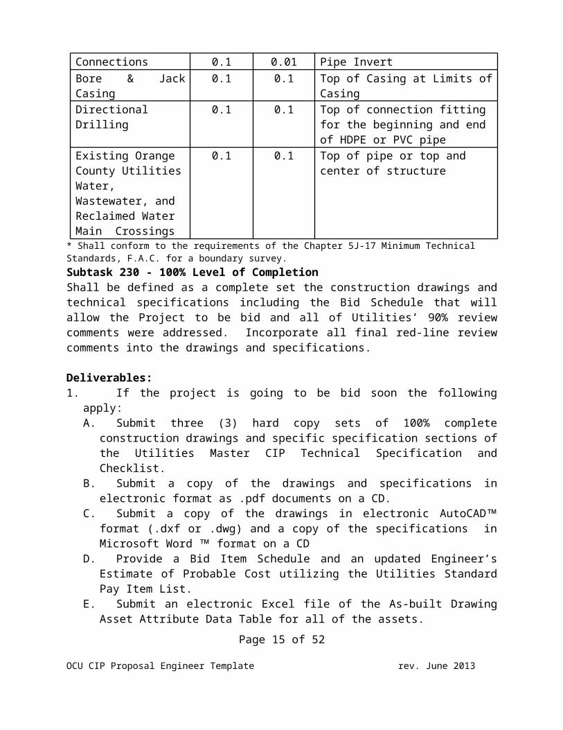
Connections 0.1 0.01 Pipe InvertBore & JackCasing
0.1 0.1 Top of Casing at Limits ofCasing
DirectionalDrilling
0.1 0.1 Top of connection fitting for the beginning and end of HDPE or PVC pipe
Existing Orange County UtilitiesWater, Wastewater, and Reclaimed Water Main Crossings
0.1 0.1 Top of pipe or top and center of structure
* Shall conform to the requirements of the Chapter 5J-17 Minimum Technical Standards, F.A.C. for a boundary survey.Subtask 230 - 100% Level of Completion Shall be defined as a complete set the construction drawings andtechnical specifications including the Bid Schedule that willallow the Project to be bid and all of Utilities’ 90% reviewcomments were addressed. Incorporate all final red-line reviewcomments into the drawings and specifications.
Deliverables:1. If the project is going to be bid soon the following
apply:A. Submit three (3) hard copy sets of 100% complete
construction drawings and specific specification sections ofthe Utilities Master CIP Technical Specification andChecklist.
B. Submit a copy of the drawings and specifications inelectronic format as .pdf documents on a CD.
C. Submit a copy of the drawings in electronic AutoCADformat (.dxf or .dwg) and a copy of the specifications inMicrosoft Word format on a CD
D. Provide a Bid Item Schedule and an updated Engineer’sEstimate of Probable Cost utilizing the Utilities StandardPay Item List.
E. Submit an electronic Excel file of the As-built DrawingAsset Attribute Data Table for all of the assets.
Page 15 of 52
OCU CIP Proposal Engineer Template rev. June 2013
2. If the project will be on hold for budgeting, then theonly documents required for each of the items defined aboveare documents that are not the same as Utilities Master orStandard drawings and specifications until the project isbudgeted.
.TASK 300 – SURVEY
Description of Project
Insert (if applicable, include linear feet of route)
TASK 300 - SURVEY
Subtask 311 - Title Search If the proposed site or alignment falls outside of a publicright-of-way, the Surveyor shall review the title work suppliedby the County, supplemental surveys and investigations and/orother record information. This information shall be shown on theSurvey, as appropriate. Recorded and unrecorded easements shallbe shown to the extent they can be identified and located on theSurvey.
Subtask 321 - Description / Sketch to Accompany Description forTemporary Construction Easement AcquisitionThe Surveyor will provide Temporary Construction Easement(s)description with sketch prepared on 8 ½” x 11” sheet(s) with a 1"x 3" blank space in upper right hand corner for recording in theOfficial Records of Orange County. The description with sketchshall meet or exceed MTS and meet Real Estate Management’srequirements. A Boundary Survey is not required for temporaryconstruction easements (for format purposes, see Example 1,“Boundary Survey for Acquisition”).
Subtask 331 - Boundary Survey for Non-acquisition PurposesProvide a Boundary Survey for fee simple property and/orpermanent easements including all improvements to the site
Page 16 of 52
OCU CIP Proposal Engineer Template rev. June 2013
described in the “Description of the Project” above. The area ofthe parcel being surveyed is estimated to be insert # acres. TheSurvey along with the Survey Map Report and/or legal descriptionshall meet the minimum requirements of Chapter 5J-17 MinimumTechnical Standards for a boundary survey.
Subtask 332 - Boundary Survey for Acquisition PurposesProvide a Boundary Survey for fee simple property and/oreasements including all improvements to the site for acquisitionby Orange County and shall be prepared on an 8 ½” x 11” sheet(s)with a 1" x 3" blank space in upper right hand corner forrecording in the Official Records of Orange County. The Surveyalong with the Survey Map Report and/or legal description (seeExample 1, “Boundary Survey for Acquisition”) shall be submittedto use in parcel acquisitions and shall the minimum requirementsof the following:1. Chapter 5J-17 Minimum Technical Standards (MTS) 2. Meet 2011 Minimum Standard Detail requirements for
ALTA/ACSM Land Title Surveys that does not include Table Aitems
3. Meet Orange County Real Estate Management requirements
The Boundary Survey shall be certified to Orange County and FirstAmerican Title Insurance Company and use the MTS certificationstatement (see General Requirements) and the ALTA/ACSMcertification statement: “This is to certify that this map or plat and the surveyon which it is based were made in accordance with the 2011 Minimum Standard DetailRequirements for ALTA/ACSM Land Title Surveys, jointly established and adopted byALTA and NSPS, and includes no Table A items. The field work was completed on___________.
The area of the parcel being surveyed is estimated to be insert #acres.
Subtask 333 - Wetlands Boundary Survey The Surveyor shall subcontract or flag by in-house staff thewetland boundaries. Wetlands delineation shall be determinedusing the Florida Unified Wetland Delineation Methodology
Page 17 of 52
OCU CIP Proposal Engineer Template rev. June 2013
detailed in Chapter 62-340, of the Florida Administrative Code(F.A.C.) and according to the U.S. Army Corps of Engineers“Regional Supplement to the Corps of Engineers WetlandDelineation Manual: Atlantic and Gulf Plain Region”, most currentversion.
Provide a Boundary Survey for the Wetlands which shall beconducted in accordance with the MTS. The wetland perimeter beingsurveyed is estimated to be insert linear feet.
Subtask 341 - Right-of-Way Locations Existing plats and land records containing the project right-of-ways shall be obtained and reviewed. Sufficient monumentationwill be recovered, field located and verified in order tocalculate and determine the right-of-way lines through theproject area, as well as any platted easements adjacent to theright-of-ways. The right-of-ways will be monumented at eachblock corner, angle point, and the beginning and end of eachcurve. This task will require setting or recoveringapproximately insert # of monuments. Found or set monuments forright-of-ways, easements and lot lines shall be adequatelydepicted on the Topographic Survey. Sufficient dimensions will beshown to support the location of the right-of-way lines relativeto the survey control baselines. Reference point details will beincluded in the CADD files provided.
Any major discrepancy between field monumentation and the right-of-way established by the surveyor shall be noted on the surveyand described within the Surveyor’s Report. The Surveyor shallnotify the Utilities Project Manager in writing the effect of thediscrepancy.
Subtask 351 - Topographic Survey Provide a Topographic Survey (see Example 3 “Topographic Surveyfor Design”) for [describe the limits of the survey]. The surveyshall be conducted in accordance with the MTS and meet therequirements of the following Table 1 Minimum Survey Accuracies,whichever is more stringent. The Surveyor shall prepare a
Page 18 of 52
OCU CIP Proposal Engineer Template rev. June 2013
Topographic Survey to provide Utilities with sufficient data todesign a proposed water, reuse, force and/or gravity main and/orpump station constructed within existing and/or proposed right ofway, easement or site. The construction corridor referencedherein (limits of the Topographic Survey) is defined as the areato be impacted by construction of the proposed improvements.Other factors outside the construction corridor shall be surveyedto support ancillary activities, such as maintenance of traffic(MOT), etc.
The horizontal and vertical spatial relationship of the aboveground natural or man-made features lying within the limits ofsurvey defined will be established and mapped. Elevations shallbe taken along the route at 100 foot intervals and at apparenthigh and low points. Spot elevations shall be taken as necessaryto identify significant elevation changes occurring within thelimits of survey. Trees having a diameter of six (6) inches(measured three feet above the ground level) lying within thelimits of survey, shall be located. Monuments shall be set forbench marks outside the limits of construction at intervals notto exceed 1,400 feet. The location of benchmarks shall becoordinated with the design such that a minimum of one monumentedbench mark is located within the limits of each sheet of theconstruction plans. The Topographic Survey shall be shown on 22”x 34” drawings at a scale of 1” = 20’.
Page 19 of 52
OCU CIP Proposal Engineer Template rev. June 2013
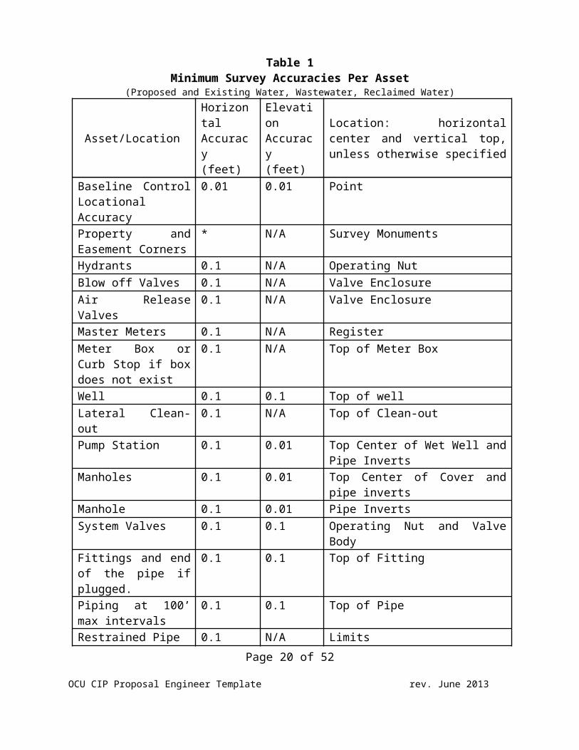
Table 1Minimum Survey Accuracies Per Asset
(Proposed and Existing Water, Wastewater, Reclaimed Water)
Asset/Location
HorizontalAccuracy(feet)
ElevationAccuracy(feet)
Location: horizontalcenter and vertical top,unless otherwise specified
Baseline ControlLocationalAccuracy
0.01 0.01 Point
Property andEasement Corners
* N/A Survey Monuments
Hydrants 0.1 N/A Operating NutBlow off Valves 0.1 N/A Valve EnclosureAir ReleaseValves
0.1 N/A Valve Enclosure
Master Meters 0.1 N/A RegisterMeter Box orCurb Stop if boxdoes not exist
0.1 N/A Top of Meter Box
Well 0.1 0.1 Top of wellLateral Clean-out
0.1 N/A Top of Clean-out
Pump Station 0.1 0.01 Top Center of Wet Well andPipe Inverts
Manholes 0.1 0.01 Top Center of Cover andpipe inverts
Manhole 0.1 0.01 Pipe InvertsSystem Valves 0.1 0.1 Operating Nut and Valve
Body Fittings and endof the pipe ifplugged.
0.1 0.1 Top of Fitting
Piping at 100’max intervals
0.1 0.1 Top of Pipe
Restrained Pipe 0.1 N/A LimitsPage 20 of 52
OCU CIP Proposal Engineer Template rev. June 2013
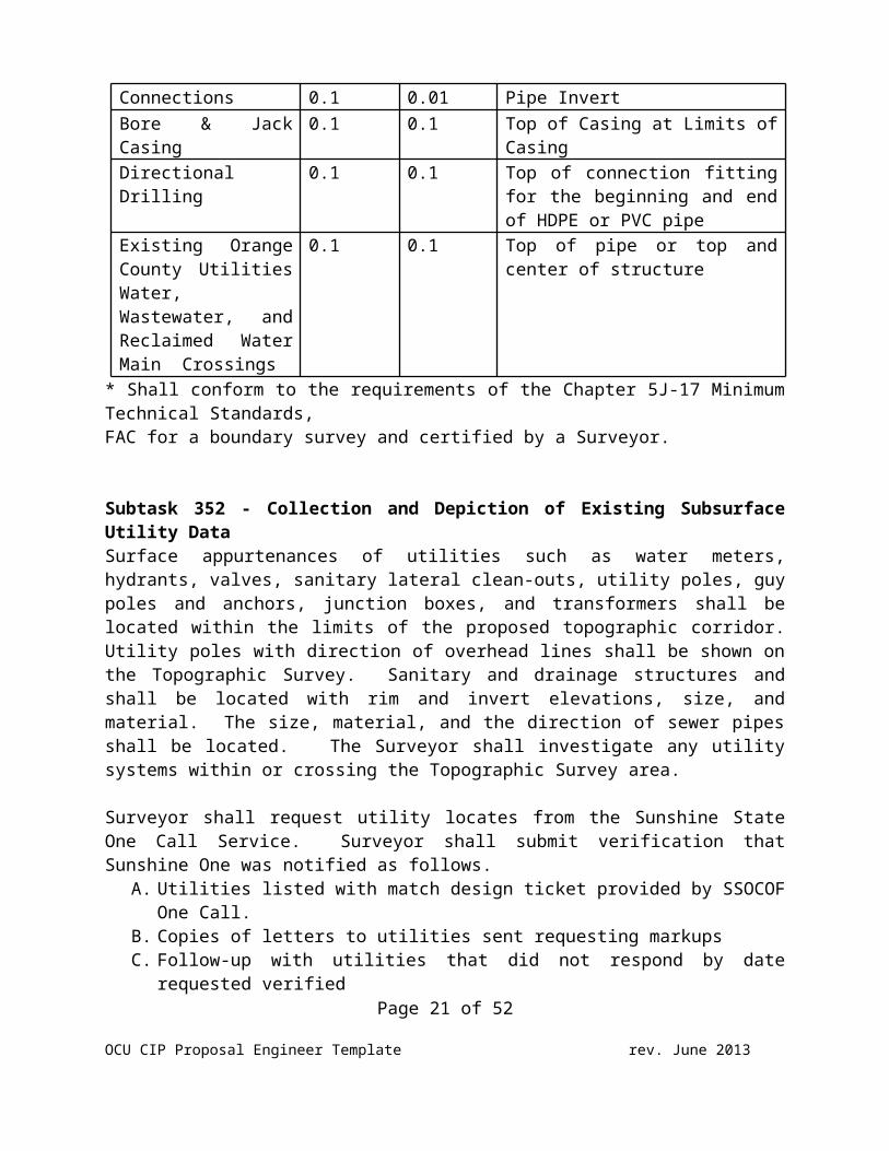
Connections 0.1 0.01 Pipe InvertBore & JackCasing
0.1 0.1 Top of Casing at Limits ofCasing
DirectionalDrilling
0.1 0.1 Top of connection fittingfor the beginning and endof HDPE or PVC pipe
Existing OrangeCounty UtilitiesWater,Wastewater, andReclaimed WaterMain Crossings
0.1 0.1 Top of pipe or top andcenter of structure
* Shall conform to the requirements of the Chapter 5J-17 MinimumTechnical Standards,FAC for a boundary survey and certified by a Surveyor.
Subtask 352 - Collection and Depiction of Existing SubsurfaceUtility DataSurface appurtenances of utilities such as water meters,hydrants, valves, sanitary lateral clean-outs, utility poles, guypoles and anchors, junction boxes, and transformers shall belocated within the limits of the proposed topographic corridor.Utility poles with direction of overhead lines shall be shown onthe Topographic Survey. Sanitary and drainage structures andshall be located with rim and invert elevations, size, andmaterial. The size, material, and the direction of sewer pipesshall be located. The Surveyor shall investigate any utilitysystems within or crossing the Topographic Survey area.
Surveyor shall request utility locates from the Sunshine StateOne Call Service. Surveyor shall submit verification thatSunshine One was notified as follows.
A. Utilities listed with match design ticket provided by SSOCOFOne Call.
B. Copies of letters to utilities sent requesting markupsC. Follow-up with utilities that did not respond by date
requested verifiedPage 21 of 52
OCU CIP Proposal Engineer Template rev. June 2013
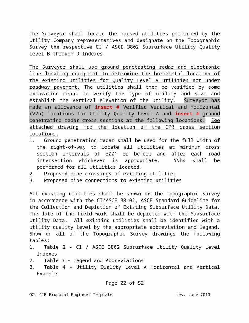
The Surveyor shall locate the marked utilities performed by theUtility Company representatives and designate on the TopographicSurvey the respective CI / ASCE 3802 Subsurface Utility QualityLevel B through D Indexes.
The Surveyor shall use ground penetrating radar and electronicline locating equipment to determine the horizontal location ofthe existing utilities for Quality Level A utilities not underroadway pavement. The utilities shall then be verified by someexcavation means to verify the type of utility and size andestablish the vertical elevation of the utility. Surveyor hasmade an allowance of insert # Verified Vertical and Horizontal(VVh) locations for Utility Quality Level A and insert # groundpenetrating radar cross sections at the following locations. Seeattached drawing for the location of the GPR cross sectionlocations.1. Ground penetrating radar shall be used for the full width of
the right-of-way to locate all utilities at minimum crosssection intervals of 300’ or before and after each roadintersection whichever is appropriate. VVhs shall beperformed for all utilities located.
2. Proposed pipe crossings of existing utilities3. Proposed pipe connections to existing utilities
All existing utilities shall be shown on the Topographic Surveyin accordance with the CI/ASCE 38-02, ASCE Standard Guideline forthe Collection and Depiction of Existing Subsurface Utility Data.The date of the field work shall be depicted with the SubsurfaceUtility Data. All existing utilities shall be identified with autility quality level by the appropriate abbreviation and legend.Show on all of the Topographic Survey drawings the followingtables: 1. Table 2 - CI / ASCE 3802 Subsurface Utility Quality Level
Indexes2. Table 3 – Legend and Abbreviations3. Table 4 – Utility Quality Level A Horizontal and Vertical
ExamplePage 22 of 52
OCU CIP Proposal Engineer Template rev. June 2013
4. The drawing note: “This drawing was prepared in conformancewith ASCE standard CE/ASCE 38-02 American Society of CivilEngineers Standard Guideline for the Collection and Depictionof Existing Subsurface Utility Data”..
Page 23 of 52
OCU CIP Proposal Engineer Template rev. June 2013
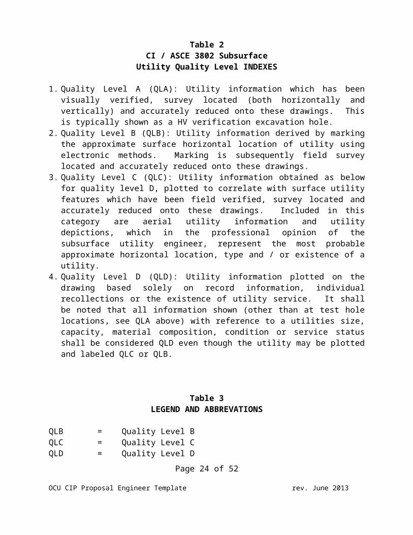
Table 2CI / ASCE 3802 Subsurface
Utility Quality Level INDEXES
1. Quality Level A (QLA): Utility information which has beenvisually verified, survey located (both horizontally andvertically) and accurately reduced onto these drawings. Thisis typically shown as a HV verification excavation hole.
2. Quality Level B (QLB): Utility information derived by markingthe approximate surface horizontal location of utility usingelectronic methods. Marking is subsequently field surveylocated and accurately reduced onto these drawings.
3. Quality Level C (QLC): Utility information obtained as belowfor quality level D, plotted to correlate with surface utilityfeatures which have been field verified, survey located andaccurately reduced onto these drawings. Included in thiscategory are aerial utility information and utilitydepictions, which in the professional opinion of thesubsurface utility engineer, represent the most probableapproximate horizontal location, type and / or existence of autility.
4. Quality Level D (QLD): Utility information plotted on thedrawing based solely on record information, individualrecollections or the existence of utility service. It shallbe noted that all information shown (other than at test holelocations, see QLA above) with reference to a utilities size,capacity, material composition, condition or service statusshall be considered QLD even though the utility may be plottedand labeled QLC or QLB.
Table 3LEGEND AND ABBREVATIONS
QLB = Quality Level BQLC = Quality Level CQLD = Quality Level D
Page 24 of 52
OCU CIP Proposal Engineer Template rev. June 2013
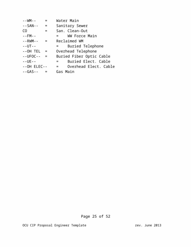
--WM-- = Water Main--SAN-- = Sanitary SewerCO = San. Clean-Out--FM-- = WW Force Main--RWM-- = Reclaimed WM--UT-- = Buried Telephone--OH TEL = Overhead Telephone--UFOC-- = Buried Fiber Optic Cable--UE-- = Buried Elect. Cable --OH ELEC-- = Overhead Elect. Cable--GAS-- = Gas Main
Page 25 of 52
OCU CIP Proposal Engineer Template rev. June 2013
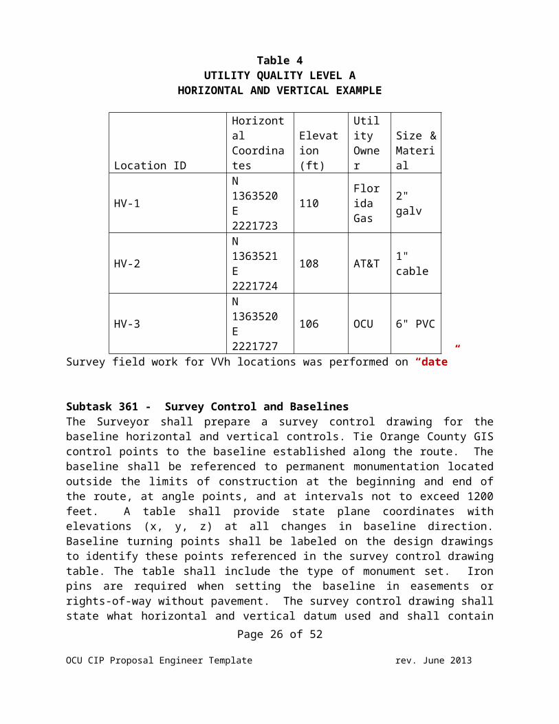
Table 4UTILITY QUALITY LEVEL A
HORIZONTAL AND VERTICAL EXAMPLE
Location ID
HorizontalCoordinates
Elevation(ft)
UtilityOwner
Size &Material
HV-1
N1363520E2221723
110FloridaGas
2"galv
HV-2
N1363521E2221724
108 AT&T 1"cable
HV-3
N1363520E2221727
106 OCU 6" PVC
Survey field work for VVh locations was performed on “date”
Subtask 361 - Survey Control and BaselinesThe Surveyor shall prepare a survey control drawing for thebaseline horizontal and vertical controls. Tie Orange County GIScontrol points to the baseline established along the route. Thebaseline shall be referenced to permanent monumentation locatedoutside the limits of construction at the beginning and end ofthe route, at angle points, and at intervals not to exceed 1200feet. A table shall provide state plane coordinates withelevations (x, y, z) at all changes in baseline direction.Baseline turning points shall be labeled on the design drawingsto identify these points referenced in the survey control drawingtable. The table shall include the type of monument set. Ironpins are required when setting the baseline in easements orrights-of-way without pavement. The survey control drawing shallstate what horizontal and vertical datum used and shall contain
Page 26 of 52
OCU CIP Proposal Engineer Template rev. June 2013
adequate graphical or written descriptions of the locations,construction and marking of all marks used or set and shallexplain methods employed in the survey and adjustment. Twohorizontal and vertical datum are required for horizontal andvertical controls. The Surveyor’s name, registration number, andthe date the survey was performed shall be labeled on the surveycontrol drawing.1. Baselines shall be parallel to the right-of-way and
monumented at the beginning and end of the project and at allchanges in direction.
2. Enough corners shall be found to determine the right-of-waysand these monuments shall be indicated on the survey.
3. GPS surveyed control baselines shall meet these postprocessed GPS survey specifications using the kinematic surveymethod. Kinematic GPS surveys make use of two or more GPSunits. At least one GPS unit is set up over a known(reference) station and remains stationary, while other(rover) GPS units are moved from station to station. Thesesurveys can be either continuous or “stop and go”. Stop andgo station observation periods are of short duration,typically under two minutes. A. Minimum number of reference stations to control the project
is 3rd order or betterB. Minimum number of check stations is 2C. Maximum distance between the survey project boundary and the
network reference control stations is 6 miles.D. Maximum PDOP during station occupation is 5.E. Minimum observation time on station is 5 epochsF. Minimum number of satellites observed simultaneously at all
stations is 5 (100% of time)G. Maximum epoch interval for data sampling is 1 to 15 secondsH. Minimum satellite mask angle above the horizon is 10
degrees. During office processing, start with a 15 degreemask.
Other control surveys shall detail the datum used and controlstations used in a manner consistent with the general survey andmap provisions of subsection 5J-17.051, F.A.C. The survey
Page 27 of 52
OCU CIP Proposal Engineer Template rev. June 2013
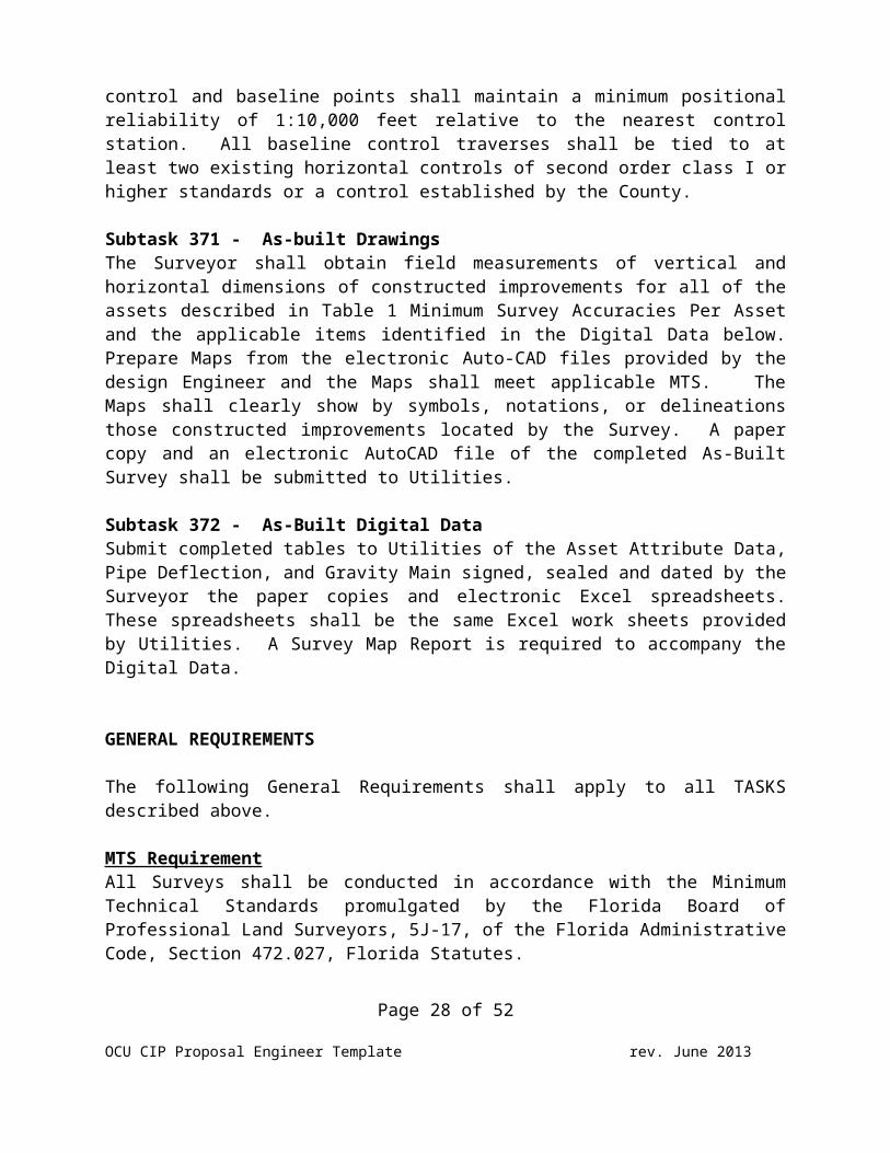
control and baseline points shall maintain a minimum positionalreliability of 1:10,000 feet relative to the nearest controlstation. All baseline control traverses shall be tied to atleast two existing horizontal controls of second order class I orhigher standards or a control established by the County.
Subtask 371 - As-built Drawings The Surveyor shall obtain field measurements of vertical andhorizontal dimensions of constructed improvements for all of theassets described in Table 1 Minimum Survey Accuracies Per Assetand the applicable items identified in the Digital Data below.Prepare Maps from the electronic Auto-CAD files provided by thedesign Engineer and the Maps shall meet applicable MTS. TheMaps shall clearly show by symbols, notations, or delineationsthose constructed improvements located by the Survey. A papercopy and an electronic AutoCAD file of the completed As-BuiltSurvey shall be submitted to Utilities.
Subtask 372 - As-Built Digital DataSubmit completed tables to Utilities of the Asset Attribute Data,Pipe Deflection, and Gravity Main signed, sealed and dated by theSurveyor the paper copies and electronic Excel spreadsheets.These spreadsheets shall be the same Excel work sheets providedby Utilities. A Survey Map Report is required to accompany theDigital Data.
GENERAL REQUIREMENTS
The following General Requirements shall apply to all TASKSdescribed above.
MTS RequirementAll Surveys shall be conducted in accordance with the MinimumTechnical Standards promulgated by the Florida Board ofProfessional Land Surveyors, 5J-17, of the Florida AdministrativeCode, Section 472.027, Florida Statutes.
Page 28 of 52
OCU CIP Proposal Engineer Template rev. June 2013
Survey shall note when the field work was completed.
Horizontal and Vertical Controls The horizontal control data shall be relative to the FloridaState Plane Coordinate system, East Zone, North American Datum of1983/1990 adjustment.
All vertical control shall be established from benchmarkspublished by Orange County or other governmental agenciesutilizing the North American Vertical Datum 1988 adjustment.
State Plane and Vertical Coordinates State plane coordinates with elevations (x, y, z) shall beprovided for all of the items listed in Table 1 Minimum SurveyAccuracies Per Asset.
CAD TemplatesIf the Surveyor is contracted in-house design by Utilities, theSurveyor shall request a current version of Utilities AutoCADTemplate for preparing final documents. The digital filesubmitted will match Orange County Utilities In-House CADStandards including but not limited to: Line-type Files, HatchPatterns, Symbol Library, Layer names, and the "stb" and "ctb"files.
Surveyor Map ReportProvide a Survey Map Report which will meet or exceed MTS. Thesurvey report should, at the very least, provide a clear,complete, and concise summery of work performed to prepare thesurvey. The Report shall include, but not be limited to: Scope,project location, survey equipment/software, survey dataresources, field monumentation and any boundary discrepancies,relative positional accuracy of measurements, flood statement,subsurface utility locates, ownership and encumbrances,jurisdictional wetland boundaries, horizontal and verticalcontrol, accuracies obtained for the survey traverse andsurveyor's certificate (see Example 2, “Survey Map Report”).
Page 29 of 52
OCU CIP Proposal Engineer Template rev. June 2013
In lieu of a Survey Map Report, information in the report shall belisted on the survey map as “Surveyor’s Notes”.
MTS Certification StatementAll survey deliverables shall be certified to Orange County anduse the following certification:“This Survey was performed in accordance with the Minimum Technical Standards asset forth by the Florida Board of Professional Surveyors and Mappers, Chapter 5J-17,Florida Administrative Code, Pursuant to Section 472.027, Florida Statutes.”
Deliverables1. A single PDF file for data collected, control, title search
of public records, last deeds of records or other datautilized in the Survey work effort.
2. Submit three (3) signed and sealed paper copies andelectronic AutoCAD and PDF files of the Topographic andBoundary Survey.
3. Submit three (3) signed and sealed paper copies andelectronic AutoCAD and PDF files of the Boundary Survey.
4. Submit four (4) signed and sealed paper copies of theTemporary Construction Easement and an electronic PDF file.
5. One (1) signed paper copy of MTS Survey Checklist completed.6. One (1) signed and sealed paper copy of Survey Map Report
and electronic PDF file.7. (Applicable when Utilities in-house forces are performing the construction.)
Submit (3) copies signed and sealed paper copies of the As-built SurveyA. Provide a complete set of scans signed and sealed by the
Surveyor. Include a TIFF image for each sheet and acomplete set in a single Adobe PDF file
B. Provide one hard copy and a CD of an Excel file of theAs-built Coordinate Asset Tables. The Surveyor shallprovide a signed and sealed report as set forth in paragraph5J-17.051(3)(b)14.b., F.A.C.
C. Provide the AutoCAD file in .dxf or .dwg format
If the County has any review comments, the Surveyor shall addressthose comments and resubmit.
Page 30 of 52
OCU CIP Proposal Engineer Template rev. June 2013
TASK 400 - GEOTECHNICAL INVESTIGATION AND GROUNDWATER SAMPLINGAND TESTING
Subtask 410 - GeotechnicalPerform a geotechnical investigation to facilitate design of theproposed main and construction of the Project. The scope ofservices is based on the supplied information and theGeotechnical Engineer’s experience in the area with sites andprojects similar to this Project. See attached map for thelocation of the proposed borings. Our exploration is planned toinclude the following:1. Stake boring locations and coordinate underground utility
clearance at the site.2. Mobilization of truck mounted drill rig and crew.3. Perform up to insert # auger borings and to a depth of
insert in the proposed pipeline alignments along the interior roadways within the subdivision and/or pump station site.
4. For projects that include proposed directional drilling or jack-and-bore construction methods, perform up to insert # Standard Penetration Test (SPT) borings to a depth of insert in the proposed pipeline alignments along the interior roadways within the subdivision and/or pump station site.
5. If pavement evaluation and/or design is required, perform upto insert # pavement cores within existing roadways to determine the functional and structural conditions of the pavement.
6. Asphalt patching for boreholes located in paved roadways.7. Perform visual classification and required laboratory
testing of the soil samples obtained from the borings. Laboratory testing may include grain size, organic testing, and corrosion analysis to verify visual classification of soiltypes.
The exploration will be supervised by a qualified Geotechnical Engineer registered in the state of Florida, and the results of the exploration will be presented in a geotechnical engineering report. The report will address the following items:
Page 31 of 52
OCU CIP Proposal Engineer Template rev. June 2013
1. Existing site conditions2. Exploration, testing and sampling methods3. Subsurface soil conditions encountered and soil
classifications4. Soil densities, if required due to proposed directional
drilling or jack-and-bore construction methods.5. Encountered pavement section characteristics and
recommendations for new pavement sections, if applicable.6. Depth to groundwater at the time of the exploration and
estimated seasonal high groundwater levels.7. A discussion of general site preparation techniques,
excavation, backfilling and fill compaction for installation of the proposed pipeline(s) and/or pump station.
Subtask 420 – Groundwater Sampling/TestingFor preparation of this proposal, the Contamination Locator Mapon the FDEP OCULUS website was used to identify if contaminatedsites were identified within or near the project site. Searchthe FDEP website for Brownfields, Petroleum, Superfund, or otherwaste cleanup sites that are currently under the FDEP’s cleanupoversight. If the project requires dewatering for theinstallation of piping or a wetwell, the Geotechnical Engineershall perform groundwater sampling at potential contaminationlocations a maximum distance of every 1,000’ along the pipe routeor at the pump station site or a 1,000’ grid in a subdivision.Ground water sampling tests will be collected at insert #locations throughout the project site and tested for the waterquality parameters specified in the FDEP Generic Permit for theDischarge of Produced Ground Water from any Non-contaminated SiteActivity, per Chapter 62-621, paragraph 62-621.300(2), F.A.C.(see www.dep.state.fl.us/Water/wastewater/iw/docs/62-621.300 _ 2 .pdf ) and the FDEP NPDES Generic Permitting.
The Geotechnical Engineer will install temporary groundwatermonitoring points at the subject locations, for the purpose ofobtaining a representative groundwater laboratory analyticalsample.
Page 32 of 52
OCU CIP Proposal Engineer Template rev. June 2013
The collected groundwater samples will be transported underproper chain of custody on wet ice to a local Florida Departmentof Health certified environmental testing facility for laboratoryanalyses of the parameters required. A finalized laboratorysummary of the analytical results of the ground water sampleswill be provided.
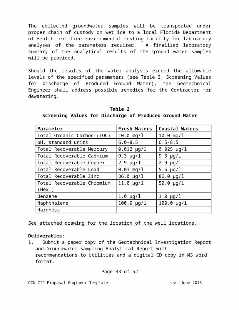
Should the results of the water analysis exceed the allowablelevels of the specified parameters (see Table 2, Screening Valuesfor Discharge of Produced Ground Water), the GeotechnicalEngineer shall address possible remedies for the Contractor fordewatering.
Table 2Screening Values for Discharge of Produced Ground Water
Parameter Fresh Waters Coastal Waters Total Organic Carbon (TOC) 10.0 mg/l 10.0 mg/l pH, standard units 6.0-8.5 6.5-8.5 Total Recoverable Mercury 0.012 μg/l 0.025 μg/l Total Recoverable Cadmium 9.3 μg/l 9.3 μg/l Total Recoverable Copper 2.9 μg/l 2.9 μg/l Total Recoverable Lead 0.03 mg/l 5.6 μg/l Total Recoverable Zinc 86.0 μg/l 86.0 μg/l Total Recoverable Chromium (Hex.)
11.0 μg/l 50.0 μg/l
Benzene 1.0 μg/l 1.0 μg/l Naphthalene 100.0 μg/l 100.0 μg/l Hardness
See attached drawing for the location of the well locations.
Deliverables:1. Submit a paper copy of the Geotechnical Investigation Report
and Groundwater Sampling Analytical Report with recommendations to Utilities and a digital CD copy in MS Word format.
Page 33 of 52
OCU CIP Proposal Engineer Template rev. June 2013
TASK 500 – ECOLOGICAL INVESTIGATION
Perform an ecological investigation to insure compliance with anypermitting requirements of the Florida Department ofEnvironmental Protection, South Florida Water ManagementDistrict, Florida Fish and Wildlife Conservation Commission, theOrange County Environmental Protection Division and othergovernmental agencies as applicable. The results of theecological investigation shall be summarized in a report thatincludes at a minimum the following.1. Identify existing wetlands; perform corridor assessment to
evaluate existence of threatened and endangered species andquality of potentially jurisdictional wetlands.
2. Request and conduct site reviews with governmental agenciesfor wetlands determination
3. Prepare reports and permit applications related to ecologicalconditions at the Project, determine mitigation requirementsand alternatives if applicable
4. Provide other biological and ecological support data asnecessary in order to represent Utilities’ interest withgovernmental agencies
Deliverables:1. Submit a paper copy of the Ecological Investigation
Report to Utilities and an electronic digital CD copy in MSWord format.
TASK 600 - PUBLIC RELATIONS: COMMUNITY MEETING/PUBLIC NOTIFICATION-FLIER PRODUCTION AND MAILING PROCEDURE
1. Following the 90% level of completion and before advertisingfor construction bids, the Engineer shall prepare and conducta pre-construction community meeting to discuss the proposedconstruction with the affected community.
2. PM establishes date for the community meeting and coordinateswith District Commissioner’s Office.
Page 34 of 52
OCU CIP Proposal Engineer Template rev. June 2013
3. Engineer identifies a location (typically an Orange Countypublic school) for the community meeting that is in proximityof the proposed construction, and provides location to PM.
4. Engineer identifies properties adjacent to or affected byproposed construction utilizing County Buffer NotificationCriteria or instructions from PM and obtains property owner’smailing address. Engineer develops mailing list and provides acopy upon request to the PM.
5. Obtain the Community Meeting Notice guidelines and coordinatewith the PM to determine the design and contents of thenotice, number of notices to be printed and the propertymailing addresses. The notice shall include the anticipatedconstruction start date.
6. Engineer coordinates with PM to develop a color, computergenerated, 8½ x 11-inch size community meeting notice withlocation map utilizing Word™ and based on OCU guidelines.
7. PM sends draft notice to Department Public Information Officer(PIO) for review and final approval by Department Director.PIO requires 10 working days from receipt of draft notice forapprovals.
8. PM has Engineer make any changes required by the PIO andEngineer sends final notice to the PM to obtain finalapprovals.
9. All notices shall meet the requirements set by the County,Utilities and the Orange County Public Notification TaskForce.
10. PrintingA. Fliers shall be printed on white glossy recycled 8 ½ x
11-inch paper B. Stock shall be a minimum of 60lb weight. And printing
shall utilize the four-color process paper.11. Property owners should receive notice two (2) weeks prior to
the meeting.12. Engineer mails Utilities approved community meeting notice.13. Construction projects that are 1 year or more in duration, a
notice shall be sent to the subject property owners every 6months and provide the status of the project.
Page 35 of 52
OCU CIP Proposal Engineer Template rev. June 2013
14. Additional notices may be needed if an urgent or emergencysituation arises on the project where public notification iswarranted.
15. Engineer shall provide a copy of the sign-in sheet andmeeting minutes to PM with five (5) days of the communitymeeting.
TASK 700 - BIDDING ASSISTANCE
1. Within 30 days before the project is advertised to be bid, revisit any easements containing proposed pipes todetermine if any protected animals (gopher turtles, eagles,etc.) have inhabited the area.
2. Create construction drawings and specificationsfor bidding and ePlan™ distribution by the Orange CountyContracts and Purchasing (Purchasing) Division. Constructiondrawings and specifications shall be formatted as .pdfdocuments and furnished to Purchasing on CD. Furnish five (5)copies of the CD containing the .pdf documents.
3. Furnish fifteen (15) sets of 24-inch by 36-inchsize hard copy of all construction drawings, one (1) unbound,single page-sided, set of technical specifications with Indexof Specification Sections and an Index of Constructiondrawings, the Bid Schedule and any Special Provisions toPurchasing for use during the bidding process.
4. Submit a list of prospective bidders.5. Attend a pre-bid conference scheduled by
Utilities.6. Consider written questions from bidders related
to the Project and prepare all addenda as required tointerpret, clarify or expand the Bidding Documents. Submitaddenda to Utilities in a timely manner that allows receptionof addenda by all bidders no later than a minimum of three (3)days prior to bid opening date.
7. Prepare a tabulation of all bids received inspreadsheet format and provide a digital copy, review andevaluate the apparent three (3) lowest bidders unit prices,
Page 36 of 52
OCU CIP Proposal Engineer Template rev. June 2013
experience and references and make recommendations toUtilities regarding the award of the construction contract.
TASK 800 - CONSTRUCTION ADMINISTRATION
Subtask 810 – Conformed Documents and Preconstruction ConferenceUtilities will provide construction inspection. All instructions to the Contractor(s) shall be issued through Utilities. The Engineer shall:1. Modify bidding documents, if required, and obtain all
County/Purchasing required and contractor executed documents;provide the County ten (10) full size and five (5) half-sizehard copy sets of the “Conformed” construction drawings andfifteen (15) complete, bound Project Manuals (collectivelyreferred to as the conformed Contract Documents) forUtilities’ use during the construction phase of the Project.
2. Conformed Construction DocumentsA. Submit one (1) certified, full size, hard copy set of
Conformed Construction Documents signed and sealed by theEngineer.
B. Submit digital Conformed Drawings in AutoCAD (dxf or dwg)format to the County.
3. Preconstruction ConferenceA. Plan, organize and conduct a pre-construction conference;
distribute ten (10) sets Conformed Contract Documents, takemeeting minutes and distribute written minutes to allattendees.
B. Provide a digital version of the conformed constructiondrawings in AutoCAD format (.dxf or .dwg) format to theContractor’s Surveyor for preparing the As-built Drawings.Provide an electronic copy of the As-Built Asset AttributeData Tables to the Contractor.
Subtask 820 – Shop Drawings and Correspondence1. Review shop drawings and product submittals for conformance
with the Contract Documents.2. Provide clarifications, interpretation of the
specifications, sketches and drawings to resolve actual fieldPage 37 of 52
OCU CIP Proposal Engineer Template rev. June 2013
conflicts encountered and provide consultation and adviceduring the construction process, as requested by Utilities.
Subtask 830 – Monthly Construction Progress Meetings1. Attend monthly construction progress meetings, take meeting
minutes and distribute minutes to all attendees. Concurrentlyon the day of the monthly construction progress meeting,observe the construction of the Project and discuss anyconcerns with Utilities.
2. The Engineer shall review the progressive As-built Drawingsand the Contractor Surveyor’s tables to determine if theconstructed improvements meet the Engineer’s design intent.
A. As-built Asset Attribute Data TableB. Pipe Deflection Table C. Gravity Main Table
3. Conduct up to one additional site visit per month to observeconstruction, if requested by Utilities.
Subtask 840 – Change Orders, Substantial Completions, and PartialCertifications 1. Utilities will execute change orders. If requested by
Utilities, evaluate requests for changes in contract price andtime made by the Contractor.
2. Conduct substantial completion inspections of Project andprepare the appropriate “punch lists”.
3. Attend pump station start-up conducted by the Contractor.4. Submit As-built drawings and necessary documents for partial
project certification of completion to the FDEP to obtain allapprovals for the release of the water main, force main,gravity main, pump station, and reclaimed water main forbeneficial use.
Subtask 850 – Final Completion Inspection and Record Drawings1. Conduct final completion inspection of Project.2. The Engineer shall develop the Record Drawings from the As-
built Drawings supplied by the Contractor. The Record Drawingsshall incorporate all partial clearance information. TheEngineer shall indicate substantive deviations from the
Page 38 of 52
OCU CIP Proposal Engineer Template rev. June 2013
original design documents and certify whether the deviationsare such that the original engineering design intent has orhas not been “materially” accomplished by the finishedconstruction. The accuracy of the location information is tobe based upon the Contractor’s Surveyor’s As-Built AssetAttribute Data Table and As-builts.
3. The Record Drawings shall be a compiled representation of theconstructed project; shall contain a listing of the sourcesand the basis of information used in the preparation of theRecord Drawings; shall contain a certification that they arebelieved to be correct to the best of the Engineer’s knowledgeand that the drawings meet the design intent including, butnot limited to, gravity main slopes, over deflecting of pipe,pipe separation, etc. Final Record Drawings combine allprevious partial clearances, contractor As-builts, surveyedcoordinates with asset table, and all Orange County Utilitieswork into one complete set.
4. The Engineer shall submit three (3) certified, full size, hardcopy sets of Record Drawings, signed and sealed by theEngineer of Record and containing appropriate notes ordisclosures accompanying the certification that state theEngineer’s determination that such modifications do or do not“materially” affect the permitted design. Exclusions are notpermitted.
5. Provide a complete set of scans signed and sealed by the Engineer of Record. Include a TIFF image for each sheet and a complete set in a single Adobe PDF file.
6. Provide the AutoCAD file in .dxf or .dwg format.
QUALITY ASSURANCE PLAN
The Engineer shall be responsible for the professional quality ofall deliverables. The Engineer shall have and shall implement aninternal Quality Assurance Plan that as a minimum provides reviewof all deliverables and significant calculations by anotherqualified professional that was not responsible for preparing thedeliverable or calculation. The Engineer’s Project Manager shall
Page 39 of 52
OCU CIP Proposal Engineer Template rev. June 2013
certify with each deliverable that the appropriate internalQuality Assurance review was performed prior to submittal toUtilities. Any exceptions will require approval by theUtilities’ Project Manager.
SCHEDULE
The work effort described herein will be completed within insert # months in accordance with the proposed schedule provided in theattached Exhibit A.
The schedule for the accomplishment of the Project reflects theproposed elapsed time in days for completion of the preliminaryengineering design, construction documents phase (final design),the bidding phase, and the construction phase of the Project. Theschedule identifies and addresses accomplishment of each taskenumerated in Utilities Standard Schedule Events. The duration ofactivities controlled by the County shall be estimated andincluded in the schedule.
COMPENSATION
In accordance with insert Contract #, the Engineer’s proposedlump sum to provide engineering services for the foregoingdescribed project for the preceding tasks 100 through 700inclusive is insert $ and an hourly not to exceed fee of insert $for Task 800 Construction Administrative Services or a total feeto provide all of the services is insert $. A cost breakdown isprovided in the attached Exhibit B Budget Detail.
The fee is separated into the following headings and work itemsare described on each corresponding line:
Task 100 Preliminary EngineeringSubtask 110 Data CollectionSubtask 120 Capacity EvaluationSubtask 130 Preliminary Engineering Report
Task 200 Construction DocumentsPage 40 of 52
OCU CIP Proposal Engineer Template rev. June 2013
Subtask 210 60% Level of CompletionSubtask 220 90% Level of CompletionSubtask 230 100% Level of Completion
Task 300 Survey Subtask 311 Title SearchSubtask 321 Temporary Construction Easement (acquisition) Subtask 331 Non-acquisition PurposesSubtask 332 Acquisition PurposesSubtask 333 Wetlands SurveySubtask 341 Right-of-Way Locations Subtask 351 Topographic SurveySubtask 352 Collection and Depiction of Existing SubsurfaceUtility DataSubtask 361 Survey Control and Baselines Subtask 371 As-built DrawingsSubtask 372 As-Built Digital Data
Task 400 Geotechnical Investigation and GroundwaterSampling/TestingSubtask 410 GeotechnicalSubtask 420 Groundwater Sampling/Testing
Task 500 Ecological InvestigationTask 600 Public Relations: Community Meeting/Public
Notification-Flier Production and Mailing ProcedureTask 700 Bidding Assistance Task 800 Construction Administration Services
Subtask 810 Conformed Documents and PreconstructionConferenceSubtask 820 Shop Drawings and CorrespondenceSubtask 830 Monthly Construction Progress MeetingsSubtask 840 Change Orders, Substantial Completions, andPartial CertificationsSubtask 850 Final Completion Inspection and Record Drawings
Fee direct costs can be determined by examination of the area ofthe project utilizing tax maps, etc.
Invoices will be submitted monthly and as described in Attachment1 Invoicing Format and Procedures.
Page 41 of 52
OCU CIP Proposal Engineer Template rev. June 2013
M/WBE PARTICIPATION
Total MBE percentage for this authorization is insert %, insertMBE firm an MBE firm and insert %, insert other MBE firm an MBEfirm will be involved in this project. The insert MBE firm’s feetotal is not to exceed fee of insert $, and insert other MBEfirm’s total not to exceed fee is insert $.
Page 42 of 52
OCU CIP Proposal Engineer Template rev. June 2013
ATTACHMENT 1
INVOICING FORMAT AND PROCEDURES
Invoices for services by the Engineer shall provide a narrativedescribing the activities being performed, date range as well asthe project specific duties / tasks performed by each personbilled to the County.
Engineer shall utilize the following format and procedures.Invoice submittals that do not meet the following format, will bedisapproved and returned to the consultant. If you have anyquestions concerning your invoice submittal, please contact thePM.
1. Invoice FormatA. Invoices shall be submitted to:
Orange County Utilities Attn: Manager, Fiscal Services Division9150 Curry Ford RoadOrlando, Florida 32825
B. A transmittal letter shall be included with the invoice.Faxed invoices are not acceptable.
C. Invoice shall have the current date of submittal and notbackdated.
D. Invoice shall have the billing period stated; forexample: “For services provided from May 1, 2009 to June 1,2009”.
E. If the invoice is a re-submittal of a previouslysubmitted invoice, the invoice shall have the words“Revised” and/or “Re-submitted” followed by the date of re-submittal.
F. Invoices shall be consecutively numbered, starting withInvoice No. 1, followed by the Purchase Order Number and theProject Name; for example: “Invoice No 1-PO C9680002; HempleAvenue Force Main Project”.
G. Invoices shall have a complete listing of tasks that areidentical to the listing of tasks in the approved scope of
Page 43 of 52
OCU CIP Proposal Engineer Template rev. June 2013
work. Each task breakdown shall include the total taskdollar amount and the dollar amount for that billing periodwith an itemization of hours by discipline and dollar amountby discipline. The sum of the dollar totals for each taskshall be equal to the fee amount.
H. A complete description of the provided services shall beincluded with the invoice.
I. All sub-consultant costs and all direct cost shall bepresented as a separate itemization.
J. All sub-consultant and direct costs shall include back-updocumentation that clearly indicates incremental costamounts.
2. Invoice Processing ProceduresA. OCUD Fiscal Services Division will mathematically review
invoice, verify documentation and submit to EngineeringDivision with their payment recommendation.
B. The Engineering Division’s Project Manager will reviewinvoice in regards to amount billed versus services receivedand either approve or disapprove invoice.
C. Disapproved invoices are returned to Fiscal ServicesDivision for return to Consultant.
D. Approved invoices are sent to Engineering Division Managerfor final approval and returned to Fiscal Services Division,which initiates the payment procedure through the Contractsand Purchasing Department. The Orange County ComptrollersOffice issues checks.
Page 44 of 52
OCU CIP Proposal Engineer Template rev. June 2013
ATTACHMENT 2
Drawing File Naming Conventions
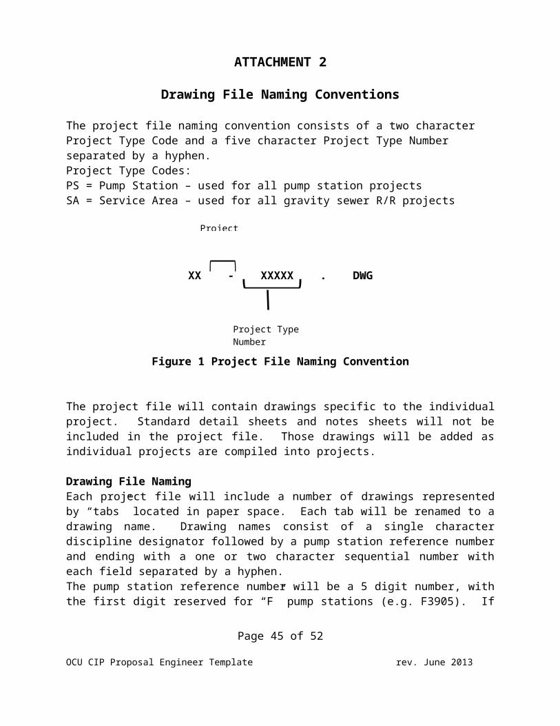
The project file naming convention consists of a two character Project Type Code and a five character Project Type Number separated by a hyphen.Project Type Codes:PS = Pump Station – used for all pump station projectsSA = Service Area – used for all gravity sewer R/R projects
XX - XXXXX . DWG
Figure 1 Project File Naming Convention
The project file will contain drawings specific to the individualproject. Standard detail sheets and notes sheets will not beincluded in the project file. Those drawings will be added asindividual projects are compiled into projects.
Drawing File Naming Each project file will include a number of drawings representedby “tabs” located in paper space. Each tab will be renamed to adrawing name. Drawing names consist of a single characterdiscipline designator followed by a pump station reference numberand ending with a one or two character sequential number witheach field separated by a hyphen. The pump station reference number will be a 5 digit number, withthe first digit reserved for “F” pump stations (e.g. F3905). If
Page 45 of 52
OCU CIP Proposal Engineer Template rev. June 2013
Project
Project Type Number
there is no “F” prefix, the pump station reference number will be4 digits.For Pump Station R/R projects the pump station reference numberwill be the pump station number. For Gravity R/R drawings thepump station reference number will contain a “SA” prefix (e.g.SA3000, SAF3905).
Page 46 of 52
OCU CIP Proposal Engineer Template rev. June 2013
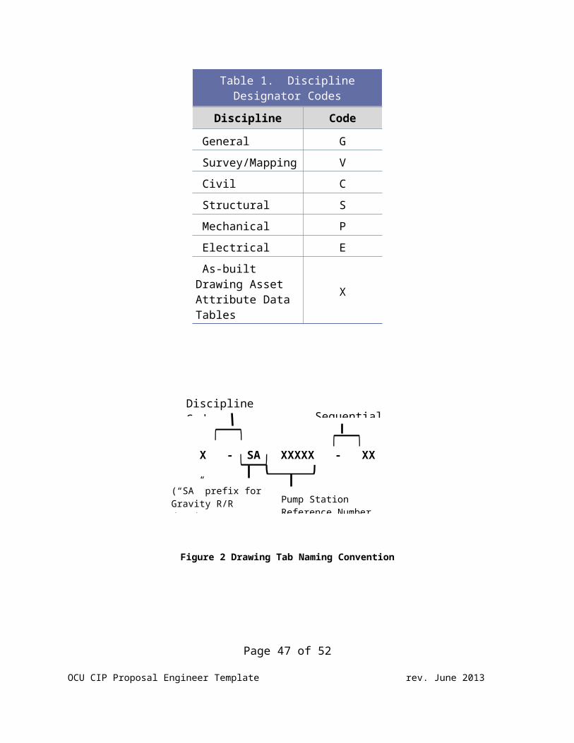
Table 1. DisciplineDesignator Codes
Discipline Code
General G Survey/Mapping V Civil C Structural S Mechanical P Electrical E As-built Drawing Asset Attribute Data Tables
X
X - SA XXXXX - XX
Figure 2 Drawing Tab Naming Convention
Page 47 of 52
OCU CIP Proposal Engineer Template rev. June 2013
Discipline Code Sequential
Pump Station Reference Number
(“SA” prefix for Gravity R/R drawings)
This sheet should be tab page.
Exhibit A
Schedule
Page 48 of 52
OCU CIP Proposal Engineer Template rev. June 2013
This sheet should be tab page.
Exhibit B
Budget Detail
Note: All subconsultants/ subcontractor fees shall be included in the budget detail sheets.
Page 49 of 52
OCU CIP Proposal Engineer Template rev. June 2013
This sheet should be tab page.
Exhibit C
Proposed Work
Preliminary Engineering Construction CostEstimate
Table 1 Water Distribution SystemImprovements
Table 2 Gravity System Improvements GIS Map Delineation for
o water main replacement locationso topographic survey limitso GPR cross sections with VVHso groundwater sampling locations
Utilities Sample R/R Schematic Drawing forCIPP Lining
FDEP OCULUS Contamination Location Map andDescriptions
Page 50 of 52
OCU CIP Proposal Engineer Template rev. June 2013
This sheet should be tab page.
Exhibit D
Subconsultant Proposal(s)
Computer Aided Drafting Services: QA/QC and Constructability Review of Final Design
phases: Surveying Services:
o Collection of Existing Subsurface Utility DataServices:
Geotechnical Investigations: Groundwater Sampling/Testing:
o Lab Analysis: Ecological Investigations: Construction Administration Services:
The Engineer is responsible for all work of their subconsultants andsubcontractors to meet the requirements of the Engineer’s proposal.
Page 51 of 52
OCU CIP Proposal Engineer Template rev. June 2013
Note: The County requires all of the subconsultant/subcontractor proposals be includedwith the Engineer’s proposal.
Page 52 of 52
OCU CIP Proposal Engineer Template rev. June 2013


 XXX ...](https://static.fdokumen.com/doc/165x107/632f67961425277a290b3945/european-commission-brussels-xxx-2013-xxx-.jpg)