
Prototype Repository – Opening and retrieval of outer section ...
SUBMISSION FOR THE SPECIAL SECTION ON APPLICATION-SPECIFIC PROCESSORS 2007 1
Outer Loop Pipelining for Application SpecificDatapaths in FPGAs
Kieron Turkington, George A. Constantinides, Member, IEEE, Konstantinos Massselos, Member, IEEE,and Peter Y.K. Cheung, Senior Member, IEEE
Abstract—Most hardware compilers apply loop pipelining toincrease the parallelism achieved, but pipelining is restricted tothe only innermost level in a nested loop. In this work we extendand adapt an existing outer loop pipelining approach known asSingle Dimension Software Pipelining to generate schedules forFPGA hardware coprocessors. Each loop level in nine test loops ispipelined and the resulting schedules are implemented in VHDLand targeted to an Altera Stratix II FPGA. The results showthat the fastest solution for all but one of the loops occurs whenpipelining is applied one to three levels above the innermost loop.Across the nine test loops we achieve an acceleration over theinnermost loop solution of up to 7 times, with a mean speedupof 3.2 times. The results suggest that inclusion of outer looppipelining in future hardware compilers may be worthwhile asit can allow significantly improved results to be achieved at thecost of a small increase in compile time.
Index Terms—Pipelining, nested loop, field-programmable gatearray (FPGA), integer linear programming (ILP).
I. INTRODUCTION
THE real-time demands of embedded applications, espe-cially those related to image, video and signal processing,
often exceed the processing capabilities of embedded micro-processors [1]. To overcome this problem custom hardwarecoprocessors may be included in the system to implement oneor more compute expensive loops within the target application,allowing the microprocessor to implement the less demandingsections of the algorithm. While hardware coprocessors candramatically increase the performance of an embedded system,their development can be a lengthy and complicated processrelative to software development. To address this problem anumber of tools have been developed that allow hardwarecoprocessors to be generated automatically from existingsoftware descriptions [2]–[5]. Of key importance when gen-erating hardware is the exploitation of parallel execution inthe algorithm as this is how acceleration is achieved. Looppipelining [6] techniques are critical in achieving efficientparallelism and are included in most hardware compilers.
Traditionally loop pipelining is applied at the innermost looplevel in a nested loop [3]–[6]. This can lead to inefficientsolutions in cases where there are dependences that crossmultiple iterations at the innermost loop, or if the innermost
This work was partially funded by the EPSRC (EP/C549481/1).K. Turkington, G. Constantinides and P. Cheung are with the De-
partment of Electrical and Electronic Engineering, Imperial College Lon-don, Exhibition Road, London SW7 2BT. e-mail {kjt01, g.constantinides,p.cheung}@imperial.ac.uk
K. Masselos is with the Department of Computer Science and Technology,University of Peloponnese, Tripolis 22100, Greece. e-mail [email protected]
loop has few iterations. A number of methods have beendeveloped in the software domain that allow nested loops tobe pipelined above the innermost level [7]–[9] and these canallow shorter schedules to be achieved. The Single DimensionSoftware Pipelining (SSP) approach [7] in particular hasbeen shown to allow shorter schedules with higher levels ofparallelism than can be achieved with inner loop methods, evenwhen loop transformations such as interchange, and unroll arealso considered. When applied to nested loops the existinghardware compilers target only the innermost loop level forpipelining. Outer loop pipelining has not yet been consideredfor hardware because it is assumed that the increase in thecontrol complexity will reduce the maximum clock rate thatcan be achieved to such an extent that any scheduling gainswill be outweighed [5].
In this work we extend and adapt the existing SSP approachto better suit the generation of schedules for hardware, specif-ically FPGAs. We also introduce a search scheme to find theshortest schedule available within the pipelining frameworkto maximise the gains in pipelining above the innermostloop. We also present a generic pipeline controller capable ofimplementing schedules pipelined above the innermost loopwithout significantly reducing the maximum clock speed ofthe final system below that which can be achieved for aninner loop only solution. Our scheduling approach is appliedto nine loop kernels to generate hardware coprocessors whichare targeted to an Altera Stratix II FPGA. The results showthat the fastest solution for each loop occurs when pipeliningis applied above the innermost loop. When compared to innerloop pipelining a maximum speedup of 7 times is achieved,with an average speedup across the nine loops of 3.2 times.
The remainder of the paper is split into seven furthersections. In Section 2 we provide a brief description of ModuloScheduling and the existing SSP methodology. Sections 3and 5 describe our extension and adaptation of this existingmethodology to improve results when targeting FPGAs, andSection 4 describes the FPGA resource constraints. In Section6 we present details of our scheme to search the solution space,along with details of our modulo scheduling formulation.Section 7 details the results achieved for nine test loops andSection 8 summarises the conclusions of this work.
II. BACKGROUND
Perhaps the most widely used loop pipelining methods arebased around modulo scheduling [6]. In modulo schedulingthe operations from a single iteration of the loop body are

SUBMISSION FOR THE SPECIAL SECTION ON APPLICATION-SPECIFIC PROCESSORS 2007 2
cycles =( p−1∏
k=0
Nk
)·(
(Np − 1) · II + (bNp − 1/Sc+ 1) ·( L+1∏
i=p+1
Ni · S · T)− bNp − 1/Sc · S · II
)(1)
scheduled into S stages, with each stage requiring T clockcycles to execute. Each operation in the loop body is assignedto start on a single cycle in a single stage. The S stages runsequentially to execute a single iteration of the innermost loop,but may all run in parallel for different loop iterations withoutbreaching the resource constraints of the target platform. Anew iteration of the innermost loop is initiated every T clockcycles with the result that the executions of S loop iterationsare overlapped.
Standard modulo scheduling based methods are limitedto pipelining (overlapping) the iterations of the innermostloop in a loop nest [6]. Single-dimension Software Pipelining(SSP) [7] extends innermost loop pipelining methods, such asmodulo scheduling, allowing them to be applied at any level ina rectangular loop nest. Under this methodology a single looplevel is selected for pipelining based upon metrics such as theexpected initiation interval for each level and/or the potentialfor data reuse. The data dependence graph for the loop nestis then simplified according to the method presented in [7].By assuming that the iterations from loop levels above andbelow the pipelined level execute sequentially, all dependencedistance vectors [10] are reduced to equivalent scalar values.This allows standard modulo scheduling techniques to beapplied to the nested loop, regardless of which level is beingpipelined. The final schedule is then constructed from themodulo schedule. A new iteration of the pipelined loop levelis initiated every T clock cycles, but an extra delay mustbe added after each group of S consecutive iterations. Thedelay added between each group is the same and its valueis defined in [7]. The extra delays are necessary to ensurethat no more than S iterations are overlapped into a pipelinewith S stages as this would cause resource conflicts. Theexisting SSP methodology has been developed for softwaretargeted to processor based platforms that offer instructionlevel parallelism.
III. EXTENDING THE SOLUTION SPACE
Standard modulo scheduling restricts the initiation interval(II) and the number of clock cycles per stage (T ) to be thesame. This restriction is maintained in the existing SingleDimension Software Pipelining (SSP) work [7]. In this sectionwe show that, when pipelining above the innermost loop level,this restriction may increase the length of the final schedule.
Let ResMII and RecMII be the lower bounds on IIset by the system’s resource and dependence constraintsrespectively. The determination of ResMII is discussed inSection 4 while the calculation of RecMII is describedin [11]. The stage length, T , must be greater than or equalto ResMII , while the minimum II is bounded by bothResMII and RecMII . Thus, in cases where the resourceconstraints are less restrictive than the dependence constraints(RecMII > ResMII), the minimum T will be less than
the minimum II . Forcing T and II to take the same valuemay therefore increase the minimum stage length that can beachieved and reduce the available solution space.
From the scheduling function presented in [7] an expressionfor the number of clock cycles required to execute a rect-angular, perfectly nested loop with L levels of nesting1 canbe obtained by substituting the values for the last operationin the loop. This is defined by equation (1). Ni representsthe number of loop iterations at level i in the nest2 and pis the loop level selected for pipelining. When a loop nestwith large loop counts is pipelined above the innermost loopthe length of the schedule is dominated by the value of T(cycles ≈ T ·∏L
i=1 Ni). Hence finding the shortest schedulemay require T to be minimised at the expense of a larger valueof II .
The original SSP work targets platforms with limited func-tional units (relative to platforms such as FPGAs where logicresources are abundant) such as VLIW processors. One wouldexpect that the limited number of functional units on theseplatforms might produce relatively tight resource constraintssuch that ResMII will typically be greater than RecMII .Hence the authors of the original work saw no need to separatethe values of T and II as they will most likely both beconstrained to the same value by ResMII . However, theabundant logic resources on modern FPGAs (please see thefollowing section for more details) may allow smaller valuesof ResMII , such that RecMII dominates. Thus we felt itworthwhile to remove the constraint for II and T to havethe same value. This extension could be applied to otherarchitectures, such as VLIW processors, but it simply extendthe scheduling effort for no significant scheduling gains.
Allowing the values of II and T to take different valuesshould enable greater acceleration over pipelining at the in-nermost loop level in cases when RecMII is greater thanResMII . However, we make no assumption about the relativevalues of RecMII and ResMII and the methodology pre-sented in the remainder of this paper is applicable in all cases.The separation of these values merely extends the availablesolution space over that offered by the original SSP work.If ResMII is greater than RecMII then the solution ourapproach finds offer less significant (if any) gains over theoriginal SSP approach.
IV. FPGA RESOURCE CONSTRAINTS
The goal of this work is to identify a compute intensiveloop nest in a target application and compile this loop to ahardware coprocessor on an FPGA. Modern FPGAs have highresource densities with the largest devices offering in excessof 105 look up tables (LUTs) and hundreds of embeddedmultipliers [12]. It may therefore be reasonable to assume
1Level L is the innermost loop and level one the outermost2NL+1 and N0 are defined to be one for uniformity

SUBMISSION FOR THE SPECIAL SECTION ON APPLICATION-SPECIFIC PROCESSORS 2007 3
that each instruction in the target loop can be implemented ona dedicated resource, ultimately producing no resource con-straints (i.e. ResMII = 1). However, while logic resourcesare abundant, the data operated on by the FPGA datapathis typically stored in off chip memories, and the numberof ports through which this data may be accessed will belimited. Often it is not the physical resources on the devicethat limit performance, but the off chip memory bandwidthavailable to access the arrays used by the application [13].The limited number of off chip memory ports acts as aconstrained resource that must be scheduled around duringpipelining, much as the limited number of adders or multipliersmust be scheduled around when targeting architectures withlimited arithmetic resources. In this work we assume that itis the number of available memory ports that will limit theparallelism that may be exploited, rather than the availablecomputational resources. It is also assumed that all functionalunits (such as multipliers) with latencies greater than a singleclock cycle are internally pipelined, which is reasonable giventhe architectures of modern FPGAs [12].
With these assumptions and an array to physical memorymap (which is must be supplied by the designer in thiswork)3 the value of ResMII for a given loop and targetplatform may be calculated based on the ratios of accessesto ports for each memory. The minimum number of clockcycles (cycm) required to execute the memory accesses tomemory m in a single iteration of the innermost loop (ignoringdependence constraints) can be computed using equation (2).Rm represents the number of reads and Wm the number ofwrites in a single iteration of the innermost loop for all ofthe arrays assigned to memory m. portsm is the number ofports4 to m, and Issrm and Isswm are the issue intervals (theminimum number of cycles between successive operations) ofthe read and write operations respectively. The final value ofResMII for the given target platform and target loop is thendefined by equation (3).
cycm =
⌈Issrm ·Rm + Isswm ·Wm
portsm
⌉(2)
ResMII = maxm
(cycm) (3)
V. IMPERFECT NESTING
In practice few loops are perfectly nested and so the Single-dimension Software Pipelining methodology is extended todeal with imperfectly nested instructions [14]. This method-ology requires the use of multiple stage lengths to achievemaximum efficiency. The implementation of multiple stagelengths in FPGA hardware would require complex controlthat would ultimately reduce the clock frequency of the finalpipeline. To avoid such complications a simpler method forscheduling imperfectly nested loops has been developed. Extraimperfect stages are added to the pipeline which execute onlyat the beginning and/or end of the loop level where they are
3The only requirement of the array to memory map is each memory issufficiently large to accommodate all the arrays mapped to it
4In this description we consider only read/write ports, but the methodologyis easily extended to deal with dedicated read and write ports
required. To prevent resource conflicts in the schedule, theimperfect stages are added in multiples (or sets) of S, whereS is the number of perfect stages. The reasoning behind thisis demonstrated using the simple example in Figure 1(a).
In this example it is assumed that the loop is first pipelinedignoring the imperfectly nested instructions and then modifiedto include them. The outermost loop is pipelined and the per-fect operations are scheduled into five stages, with an initiationinterval of two stages5. Once the pipeline has been filled theperfect schedule follows the pattern shown in Figure 1(b). Thestepped bold line in Figure 1(b) marks on each outer loopiteration the end of one iteration of the middle loop level andthe start of the next. To implement the full imperfect loop theexecution of imperfect operations must be inserted along thisline.
Assuming that all of the imperfect operations can be exe-cuted in a single pipeline stage the obvious schedule wouldbe that shown in Figure 1(c). However this schedule causesmultiple iterations to require the same stage at the same time,which is not allowed. A possible solution to this problem isto include extra (possibly empty) imperfect stages so that thenumber of imperfect stages matches the length of the initiationinterval (two in this case). This does remove the stage conflicts,as shown in Figure 1(d), but it also creates a new problem.Both the imperfect stages (X0 and X1) must run in parallelwith each of the perfect stages at some point in the schedule.This may make it impossible to assign a constrained resourceto any cycle in the imperfect stages without conflicting witha perfect stage. This problem will persist for any number ofimperfect stages fewer than S (five in this case). Figure 1(e)shows that there are no stage conflicts when five imperfectstages are used. Furthermore, each imperfect stage always‘replaces’ one particular perfect stage in the schedule. Forexample, stage X0 always executes in time slots that wouldbe allocated to perfect stage 0 in the original perfect schedule.Hence, provided the resource usage pattern of the imperfectstage matches that of the perfect stage it replaces, there willnever be resource conflicts in the imperfect schedule.
Let Ii be the set of imperfectly nested operations that mustexecute at the start/end of an iteration at level i in the loop nest.The start (or end) of an iteration at level i always entails thestart (or end) of an iteration at level i+1. The set of imperfectoperations executed for level i + 1 is therefore a subset ofthe operations executed for level i. As we move outwardsfrom the innermost loop the number of imperfectly nestedinstructions may increase. Hence, to improve the efficiencyof our approach, we allow an increasing number of sets ofstages to be included for each level in the loop above theinnermost loop. We define Zi to be the number of sets ofstages included in the schedule to accommodate all imperfectlynested operations up to and including loop level i. Only theloop levels up to and including the pipelined level, p, areimplemented on the FPGA. Hence the total number of setsof imperfect stages included in the schedule for the FPGAhardware is Zp.
5These values are chosen arbitrarily for the example and are not critical.

SUBMISSION FOR THE SPECIAL SECTION ON APPLICATION-SPECIFIC PROCESSORS 2007 4
for (i = 0; i < Ni; i++) for (j = 0; j < Nj; j++){ imperfect_ops for (k = 0; k < Nk; k++){
perfect_ops } }
(a)
i
time
0 1 2 3 4
0
3
4
1
2
1
2
4
3
0
0
4
1
3
2
3
4
1
0
2
2
3
4
4
2
0
0
1
1
3
4
0
3
4
1
2
1
2
0
3
2
0
1
3
4
0
1
2
3
4
(b)
i
time
4
0
3
4
1
2
1
2
0
3
X0
2
3
4
4
2
0
0
1
1
3
X0
2
0
1
3
4
0
1
2
3
4
X0
0
4
1
3
2
3
4
1
0
2
X0
0
3
4
1
2
1
2
4
3
0
X0
0 1 2 3 4
(c)
i
time
0
3
4
1
2
1
2
4
3
0
X0
X1
0
4
1
3
2
3
4
1
0
2
X0
X1
2
0
1
3
4
0
1
2
3
4
X0
X1
2
3
4
4
2
0
0
1
1
3
X0
X1
4
0
3
4
1
2
1
2
0
3
X0
X1
0 1 2 3 4
(d)
i
time
0
3
4
1
2
1
2
4
3
0
X0
X1
X2
X3
X4
0
4
1
3
2
3
4
1
0
2
X0
X1
X2
X3
X4
2
0
1
3
4
0
1
2
3
4
X0
X1
X2
X3
X4
2
3
4
4
2
0
0
1
1
3
X0
X1
X2
X3
X4
4
0
3
4
1
2
1
2
0
3
X0
X1
X2
X3
X4
0 1 2 3 4
(e)
Fig. 1. Scheduling imperfectly nested operations. Each numbered box represents an execution of the stage denoted by the enclosed number. Each verticalcolumn of stages represents part of the execution of one of the first five outer loop iterations. (a) A sample loop nest (b) A section of the perfectlynested schedule. (c) Extending the perfectly nested schedule to include one imperfect stage. The shaded grey boxes represent imperfectly nested stages.The black circles mark out an example of a resource conflict in the schedule (d) Extending the perfectly nested schedule to include two imperfect stages(e) Extending the perfectly nested schedule to include five imperfect stages
VI. SCHEDULING
In this work the goal is to find the optimum (shortest)schedule available within the restrictions of our frameworkand the memory port constraints of the target platform. Therelatively large number of variables present, even for smallloops, makes optimal scheduling within resource constraints adifficult problem. For this reason our scheduling approach issplit into two parts. The first part is a search of the possiblevalues for the stage length, T , the number of perfect stages, S,the number of sets of imperfect stages, Zp, and the initiationinterval, II . The second part is an Integer Linear Programming(ILP) [15] based modulo scheduling formulation that assignsstart times to the loop operations for fixed values of T , S andZp so that either the initiation interval or the total number ofstages executed is minimised.
The two inputs to the scheduling process are the datadependence graph for the nested loop and an array to physicalmemory map. The data dependence graph, G(V, E), comprisesa set of nodes, V , and a set of edges E. Each node, vn,represents an operation in the loop nest. Each edge, (vn1, vn2),represents a dependence between nodes vn1 and vn2, withvn2 dependent on vn1. Edge (vn1, vn2) is tagged with adependence distance vector, dn1n2, denoting the number ofloop iterations separating the dependent instances of vn1 andvn2 at each loop level. The data dependence graph is simplifiedfor each loop level. Each dn1n2 is reduced to single scalarvalue, dn1n2, which denotes the number of loop iterationsseparating the dependent operations at the pipelined loop level.Further details concerning the form of the data dependencegraph and the dependence simplification can be found in [7].Further to the dependence simplification, all operations (nodes)nested above the pipelined level are removed from the graphas only operations from the pipelined loop level and below areimplemented in the hardware coprocessor on the FPGA.
A. Searching the Solution Space
When pipelining an imperfectly nested loop at an arbitrarylevel, p, the length of the schedule is defined by equations (4)and (5). Stot represents the total number of stages executedduring a single iteration of the loop at the pipelined level andeach Zi represents the number of sets of imperfect stagesincluded for level i in the loop6. Equation (4) is simply aweighted sum of the number of sets of stages nested at eachlevel in the loop and equation (5) is simply the imperfectgeneralisation of equation (1). From these expressions it is notimmediately clear how the scheduling parameters (T , S, IIand the Zi values) should be traded to find the schedule withthe shortest execution time. To this end the search schemepresented in Algorithm 1 has been developed. Algorithm 1must be executed for each level in the target loop.
The search begins by calculating the value of ResMIIbased on the port constraints for the target platform andloop, as described in Section 4. The scheduling options areexplored for increasing values of T until a bounding conditionis satisfied. For any given value of T the minimum schedulelength according to equation (5) is
(T ·∏L
i=1 Ni
)cycles. The
search terminates when a value of T is reached such that thislower bound schedule length is greater than the length of thebest schedule already found.
For each value of T the minimum value of S is found.The scheduling options are then explored for increasing valuesof S until a bounding condition is breached. For each Tthe minimum II and Stot values are estimated as theseare required to bound the search. For each candidate S thelower bound schedule length is calculated assuming that theestimated minimum II and Stot values may be achieved. Itis also assumed that S is a factor of Np as this removes the
6Zi is defined to be zero for all i ≥ L

SUBMISSION FOR THE SPECIAL SECTION ON APPLICATION-SPECIFIC PROCESSORS 2007 5
Stot = S ·(
L∑
i=p+2
(Zi · (Ni − 1) ·
i−1∏
j=p+1
Nj
)+ (Np+1 − 1) · Zp+1 + Zp +
L+1∏
i=p+1
Ni
)(4)
cycles =( p−1∏
k=0
Nk
)·(
(Np − 1) · II + (bNp − 1/Sc+ 1) · Stot − bNp − 1/Sc · S · II
)(5)
Algorithm 1 : Searching the pipelining solution space for eachloop level. Latimp represents the sum of the latencies of allimperfect operations nested up to the pipelined level
1: best = ∞;2: T = find ResMII();3: while bound1(T) < best do4: S = find S min(T);5: II est = estimate II min(T);6: S tot est = estimate S tot min(T, S);7: while bound2(T, S, II est, S tot est) < best do8: Zp = find Zp min(T, S);9: while Zp ≤ Latimp do
10: II = find II min(T, S, Zp);11: S tot min = find S tot min(T, S, Zp);12: done = true;13: while bound3(T, S, S tot min, II) < best do14: cycles = schedule(T, S, Zp, II);15: best = min(cycles, best);16: II++;17: end while18: Zp++;19: end while20: S++;21: S tot est = estimate S tot(T, S);22: end while23: T++;24: end while
ceiling and modulus functions from equation (5), making theschedule length a monotonic increasing function of S. Whenan S value is reached such that this lower bound is greaterthan the length of the current best schedule, the search is ableto progress onto the next value of T .
For each value of S the minimum value of Zp is found andthe scheduling options are explored for increasing values ofZp. Let Latimp be the sum of the latencies for all imperfectoperations up to and including the pipelined level. IncludingLatimp sets of imperfect stages in the schedule allows everyordering for the imperfect operations within the dependenceand resource constraints to be reached. The optimum II andStot values can therefore always be achieved within Latimp
sets of imperfect stages. Increasing the value of Zp aboveLatimp will always increase the schedule length and so thesearch may progress onto the next S value once a Zp valueof Latimp is reached. A similar bounding approach is alsoemployed for the range of S values. The value of S isnever increased above Lattot, where Lattot is the sum ofthe latencies for all of the operations in the loop up to andincluding the pipelined level.
For each Zp the minimum values of II and Stot arefound (not estimated). Modulo scheduling of the loop isthen performed for the current values of S, T and Zp with
increasing values of II . The goal during modulo scheduling isthe minimisation of Stot as this yields the minimum schedulelength for the given values of T , S, Zp and II . The lowerbound schedule length for each value of II is calculated usingequation (5) by assuming that the minimum Stot may beachieved. Once an II value is reached such that the lowerbound exceeds the length of the best schedule already found,the search progresses to the next Zp value.
The schedule, find S tot min and find II min functionsall make use of the ILP modulo scheduling formulationdescribed described in Section 6.2. The functions set differentvariable bounds and minimise different cost functions whichare discusses at the end of Section 6.2. The find Z p minfunction also uses the scheduling formulation to find theminimum Zp, attempting to schedule for increasing valuesof Zp until a feasible solution is found. The find S min andestimate II min functions utilise a simplified version of thescheduling formulation that does not model the imperfectlynested resource constraints. While find S min is able to returnthe true minimum S for the given T (because S is only de-pendent on how the perfectly nested operations are scheduled),estimate II min returns an estimate of the minimum II for thegiven T . However, it will never return a value greater than thetrue minimum and so this value can still be used for generatinglower bound schedule lengths.
estimate S tot min is a much simpler function that doesnot attempt any scheduling. Instead each Zi value is estimatedbased on the number of clock cycles required to complete allof the memory accesses nested perfectly or imperfectly upto and including loop level i, ignoring all dependences. Theestimated Zi values, along with the given value of S, allow anestimate of the minimum Stot to be found using equation (4).The estimated value for the minimum Stot will never exceedthe true minimum and so can be used to generate lower boundschedule lengths.
The number of iterations of the innermost loop in the searchwill vary from target loop to target loop. However, the worstcase size of the search can be calculated based on the worstcase ranges of the T , S, Zp and II variables. It can beshown that the worst case range of values for each variable isapproximately Lattot, where Lattot is the sum of the latenciesfor all of the operations in the simplified data dependencegraph. Hence the number of inner loop iterations will be ofthe order of Lat4tot. While this represents a potentially largenumber of iterations, for the test cases presented in Section 7the search was found to bound after far fewer iterations.

SUBMISSION FOR THE SPECIAL SECTION ON APPLICATION-SPECIFIC PROCESSORS 2007 6
B. Modulo Scheduling
Modulo scheduling of the simplified dependence graph isimplemented using ILP as this provides a simple methodfor obtaining schedules with minimal cost functions. Thecost functions used are discussed at the end of this section.In the ILP formulation the start time of each node, vn, inthe simplified dependence graph, Gs(Vs, Es), is defined asan integer variable xn. The latency of each operation isdefined as an integer constant ln. Each edge in Es produces alinear constraint in the scheduling formulation, as describedby equation (6). II is an integer variable representing theinitiation interval. dn1n2 again represents the number of loopiterations at the pipelined loop level between the dependentinstances of nodes vn1 and vn2.
∀(vn1, vn2) ∈ Es, xn2 + dn1n2 · II ≥ xn1 + ln1 (6)
Recall that within each individual modulo scheduling for-mulation the values of T , S and Zp are constants. Theperfectly nested operations may only be scheduled to start inthe S perfect stages and every perfect operation must completeits execution before the end of the final perfect stage. Theserequirements lead to the constraints in equations (7) and (8),which assume the first perfect stage begins its execution attime t = 0. P is the set of all perfectly nested operations inthe dependence graph.
∀vn ∈ P, xn + ln ≤ S · T (7)∀vn ∈ P, xn ≥ 0 (8)
The imperfectly nested operations may be scheduled into anyof the perfect or imperfect stages, but must all complete beforethe end of the final imperfect stage. The Zp ·S imperfect stagesmay be considered to execute both before and after the perfectstages and so the constraints in equations (9) and (10) must bemet during scheduling. I is the set of all imperfectly nestedoperations in the dependence graph.
∀vn ∈ I, xn + ln ≤ Zp · S · T (9)∀vn ∈ I, xn ≥ −Zp · S · T (10)
For each level i above the innermost loop and below thepipelined loop the value of Zi (which is defined as an integervariable) must be determined during scheduling. Since theimperfectly nested operations may be scheduled to executeeither before or after the perfect stages the Zi values areconstrained by both equations (11) and (12). Ii is the set ofoperations nested imperfectly up to and including loop leveli.
∀vn ∈ Ii, Zi · S · T ≥ −xn (11)∀vn ∈ Ii, Zi · S · T ≥ xn + ln − S · T (12)
The remainder of the variables and constraints in our mod-ulo scheduling formulation are required to model the resourceconstraints of the target system. For each physical memory, m,the value of cycm is re-calculated according to equation (2),this time including both the perfect and imperfect memoryoperations in the values of Wm and Rm. Let impm be thenumber of imperfectly nested accesses to memory m in the
simplified data dependence graph. The resource constraints formemory m will take one of three forms depending on thevalues of cycm and impm.
1) cycm ≤ 1 : In this case it is possible to executeall accesses (both perfectly and imperfectly nested) tomemory m in parallel. As such no resource constraintsare required for the access operations to this memory.
2) cycm > 1 and impm = 0 : In this case there areinsufficient ports to execute every memory access inparallel, but it must still be possible to execute allS perfect stages in parallel. For each memory accessoperation, vn, assigned to memory m a new integervariable, stn, and T binary variables, dnt
7, are defined.stn defines the stage to which operation is assignedwhile the dnt binary variables determine the cycle withinthe stage. dnt is one if operation vn is scheduled tobegin on cycle t and zero otherwise. The start time ofoperation vn is then constrained by equations (13) and(14). The constraints defined by equation (15) ensurethat, when all S perfect stages execute in parallel, nomore accesses are scheduled to a single cycle than canbe supported by the available ports, portsm. Pm is theset of perfect memory accesses to memory m.
∀vn ∈ Pm, xn = stn · T +T−1∑t=0
t · dnt (13)
∀vn ∈ Pm,
T−1∑t=0
dnt = 1 (14)
∀0 ≤ t ≤ T,∑
vn∈Pm
dnt ≤ portsm (15)
3) cycm > 1 and impm > 0 : In this case the constraintsmust ensure that all of the perfect stages may executein parallel without breaching the port constraints. Theymust also ensure that each imperfect stage uses nomore ports on each cycle than the corresponding perfectstage. The resource constraints required for multiplesets of imperfect stages (Zp > 1) differ from those for asingle set of stages (Zp = 1). Due to space constraintsonly the constraints for a single set of imperfect stagesare described since the optimal solution for the loops wetarget normally requires only a single set of imperfectstages. For each perfectly nested memory operation, vn,assigned to memory m, an extra S · T binary variables,dnst
8, are defined. dnst is defined to be one if operationvn is scheduled to begin on cycle t of perfect stages and zero otherwise. The scheduled start time of vn,xn, is then constrained by equations (16) and (17). Pm
again represents the set of perfect memory accesses tomemory m.
7(0 ≤ t < T )8(0 ≤ s < S) and (0 ≤ t < T )
SUBMISSION FOR THE SPECIAL SECTION ON APPLICATION-SPECIFIC PROCESSORS 2007 7
∀vn ∈ Pm, xn =S−1∑s=0
T−1∑t=0
(s · T + t) · dnst (16)
∀vn ∈ Pm,
S−1∑s=0
T−1∑t=0
dnst = 1 (17)
For each imperfectly nested memory operation, vn,assigned to memory m, a further S ·T · (Zp +1) binaryvariables, dnρst
9, are defined . dnρst is defined to beone if operation vn is scheduled to cycle t of stage s.If ρ is zero the imperfect operation is scheduled to aperfect stage, otherwise it is scheduled to an imperfectstage. A further binary variable, ban, is also defined.ban is one if vn is scheduled to start after the executionof the perfect stages and zero otherwise. The start timeof vn, xn, is then constrained by equations (18) and(19). Im represents the set of imperfect access operationsassigned to memory m.
∀vn ∈ Im,
xn =1∑
ρ=0
S−1∑s=0
T−1∑t=0
((−ρ · S · T + s · T + t) · dnρst
)
+ 2 · ban · S · T (18)
∀vn ∈ Im,
1∑ρ=0
S−1∑s=0
T−1∑t=0
dnρst = 1 (19)
The resource constraints for memory m in the imperfectsystem are defined by equations (20) and (21). Equa-tion (20) defines the resource constraints for the perfectstages while equation (21) deals with the imperfectstages. Each imperfect stage is constrained to use nomore memory ports than the corresponding perfect stage.In cases where not all of the memory ports are utilisedon every cycle in the perfect stages, the slackmst integervariables allow the imperfect stages to make use of these‘spare’ access slots.
∀ 0 ≤ t < T,S−1∑s=0
( ∑
vn∈Pm
dnst +∑
vn∈Im
dn0st + slackmst
)
≤ portsm (20)
∀ 0 ≤ s < S, ∀ 0 ≤ t < T,∑
vn∈Im
dn1st ≤∑
vn∈Pm
dnst +∑
vn∈Im
dn0st
+ slackmst (21)
The modulo scheduling routine is called numerous timesby the search routine with different values of T , S, and Zp
as inputs. The cost function which must be minimised variesdepending on which function in the search which makes thescheduling call. The schedule and find S tot min functions
9(0 ≤ ρ < Zp), (0 ≤ s < S) and (0 ≤ t < T )
require the minimisation of Stot, which is defined as an integervariable and whose value is determined by equation (4). Theschedule function also places an upper bound on the value ofII . The find II min function uses II as the cost function.
The II value returned by the ILP formulation may causeresource conflicts in certain cases. Although a proof is notincluded due to space constraints it can be shown that, whenII and T have different values, the constraints that II is aninteger multiple of T and that the greatest common divisor(gcd) of (II/T ) and S equals one must be met. When theseconstraints are not met by the II value returned from the ILPthe minimum legal II for the given values of T and S maybe found by increasing II to the next integer multiple of Tsuch that the gcd of (II/T ) and S is one.
VII. HARDWARE IMPLEMENTATION
Extending loop pipelining above the innermost loop doesnot add any additional complexity to the generation of theresulting datapaths. The automatic generation of VHDL dat-apaths from pipelined schedules has received considerableattention in existing work [3], [5] and no real extensionsbeyond current methods are required when moving above theinnermost loop. However, the hardware control structures forloops pipelined above the innermost level have not previouslybeen considered and this section proposes a novel method fortheir implementation.
The hardware controller for a pipelined loop must supplythe following signals to the datapath:
1) A signal to indicate which of the T clock cycles in eachstage is being executed. The stages run in lock step sothe same signal supplies every stage.
2) A signal to indicate which of the stages in the pipelineare enabled. During the pipeline fill and flush (and ifthere are imperfect stages in the pipeline) the correct setof stages must be disabled or enabled to ensure correctoperation.
3) A set of signals to indicate the current loop iterationbeing executed by each stage in the pipeline.
When pipelining at the innermost loop level these signals canbe supplied by relatively simple circuit, such as those shown inFigures 2(a) and 2(b). A counter and shift register supply thecorrect loop index to each of the S stages while a comparatorand a second shift register determine the enable signals. Thecircular shift register in Figure 2(a) tracks the current cycle ineach stage. Execution of the pipeline is triggered by settingthe reset input high for a single cycle. The simplicity of such acontrol scheme will generally create a relatively short criticalpath through the control logic which should be comparable tothe critical path in the datapath logic. Hence a high maximumclock rate can generally be achieved. For any outer looppipelining scheme to be worthwhile it must be possible toimplement the controller in a comparably simple manner toensure that any drop in clock frequency is minimised. If thisis not the case then any potential decrease in the schedulelength with be canceled by the drop in clock rate.
In deriving a control scheme for outer loop pipelining wefirst consider the generation of the loop index vectors for

SUBMISSION FOR THE SPECIAL SECTION ON APPLICATION-SPECIFIC PROCESSORS 2007 8
Cycle[0] Cycle[1] Cycle[T-1]
0 0
Reg
D Q >
Reg
D Q >
0 1
0 1
Reg
D Q >
0 1
Clock Reset
1
(a)
Reset
Clock
Cycle[T-1]
Count_0 Count_S-1 Count_1
Enable_0 Enable_1 Enable_S-1
1 0 0
Reg
D Q
Enable
>
Reg
D Q >
Enable
Counter
CT=0
Enable CT
>
Comparator
B
A>B A N-1 Reg
D Q >
Enable
0 1
0 1
Reg
D Q
Enable
>
Reg
D Q >
Enable
0 1
(b)
Fig. 2. A simple controller design for a loop pipelined at the innermost level (a) A cyclical shift register to indicate the current cycle in each stage(b) Control logic to generate the loop index and enable signal for each stage. The bold bus lines are of width log2N , where N is the number of loop iterations
0 (0,0)
2 (0,0)
1 (0,0)
0 (1,0)
2 (1,0)
1 (1,0)
0 (2,0)
2 (2,0)
1 (2,0)
0 (0,1)
2 (0,1)
1 (0,1)
0 (0,2)
2 (0,2)
1 (0,2)
0 (1,1)
2 (1,1)
1 (1,1)
0 (1,2)
1 (1,2)
0 (2,1)
2 (2,1)
1 (2,1)
0 (0,3)
(a)
0 (0,0)
2 (0,0)
1 (0,0)
0 (1,0)
2 (1,0)
1 (1,0)
0 (2,0)
2 (2,0)
1 (2,0)
0 (0,1)
2 (0,1)
1 (0,1)
0 (0,2)
2 (0,2)
1 (0,2)
0 (1,1)
2 (1,1)
1 (1,1)
0 (1,2)
1 (1,2)
0 (2,1)
2 (2,1)
1 (2,1)
0 (0,3)
0 (-1,8)
2 (-1,8)
1 (-1,8)
2 (-2,8)
2 (-1,7) 1 (-2,8)
(b)
Fig. 3. A section of an example schedule for a double nested loop pipelinedat the outermost level. It is assumed the loop has 9 iterations at each level andit has been scheduled into a pipeline with 3 stages and an initiation intervalof 2 stages. These numbers are chosen arbitrarily. Each box represents theexecution of one pipeline stage. The number outside the brackets in each boxis the stage number while the numbers in brackets represent the index vectorfor the loop iteration executed by each stage.
each stage. A counter is sufficient for this purpose in theinnermost loop case because each stage executes the loopiterations in sequence (i.e. 0, 1, 2...). This is not the case whenpipelining above the innermost loop. Consider the exampleschedule segment shown in Figure 3(a). Starting from thehighlighted stage, with time progressing vertically downwards,stage 0 executes the loop iterations in the order (1,0), (0,1),(2,0), (1,1), (0,2), (2,1) and so on. This is a more complexpattern than a simple increment of the innermost loop indexfrom one execution of a stage to the next. However, lookingdown the columns of the schedule it is apparent that stages 1and 2 execute the same iteration as the immediately precedinginstance of stage 0. Thus a shift register can still be used tosupply all but stage 0 with the correct index vector, reusingthe index vector from stage 0 as with inner loop pipelining.Furthermore, it is noted that the index vector for each instanceof stage 0 is merely the index vector from the precedinginstance of stage 2 with the inner loop index incremented10.
The circuit in Figure 4 is therefore sufficient to provide the
10When the inner loop index reaches total iteration count for innermostloop it is reset to zero and the index for the next loop level is incremented
Reg
D Q
Enable
>
0 1
Reg
D Q
Enable
>
0 1
Incrementer Input Output
Count_0 Count_S-1 Inc_in/ Disable
Inc_out
Clock Cycle[T-1]
Reset
3 5 Inc_in/ Disable
Inc_out
Fig. 4. A circuit to generate the loop index for each stage at one level inthe loop. The bold bus lines are of width log2N , where N is the number ofloop iterations at the given loop level. The ‘Incrementer’ block is detailed inFigure 5. The input values on the ‘1’ input of the multiplexors (3 and 5 inthis Figure) represent the initial reset values for the loop indices. The valuesshown were chosen arbitrarily and are not significant.
loop index to each stage for a single level in the loop. Thecircuit is duplicated for each loop level up to and includingthe pipelined level to provide the complete index vector foreach stage. The contents of the ‘incrementer’ block depend onthe level in the loop. Figure 5 details the ‘incrementer’ designfor the innermost loop level, the design for the pipelined looplevel and the design for all other levels in between.
Due to the feedback loop present in the circuit in Figure 4the index vectors for each stage must be initialised correctlyfor the circuit to function as hoped. Fortunately these initialvalues may be derived simply from the proposed scheduleand set as constants within the circuit. To derive the initialindex vector for each stage we extend the schedule back to thestart of the loop execution as shown in Figure 3(b). The indexvectors in the highlighted stages are the values that would bepresent if the loop were executed repeatedly with no breakbetween one execution and the next i.e. they are the indexvectors for the end of the loop execution. As these indexvectors pass through the ‘incrementer’ blocks at each levelthey will overflow back to the start of the loop execution,resulting in the desired initialisation. To ensure the correctoperation of the loop the highlighted stages in Figure 3(b) willnot be enabled and so no datapath operations will be executedfor them.
The ‘Inc out’ signal generated by the ‘incrementer’ blockat the pipelined level, referred to as ‘Inc top’ from here on,may seem superfluous as there are no higher loop levels forit to feed into. However, it is useful in the control of thegeneration of the correct enable signal for each stage. The
SUBMISSION FOR THE SPECIAL SECTION ON APPLICATION-SPECIFIC PROCESSORS 2007 9
A
B A=B
Comparator
A+B
A
B
N-1
1 0
Input
Output
Disable
Inc_out
0 1
(a)
A
B A=B
Comparator
A+B
A
B
0 1 0
1
N-1
1 0
Input Output
Inc_in
Inc_out
(b)
A
B A>B
Comparator
A+B
A
B
0 1 0
1
1
Input Output
Inc_in
Inc_out
A- B
A
B N-S
N-(S+1)
(c)
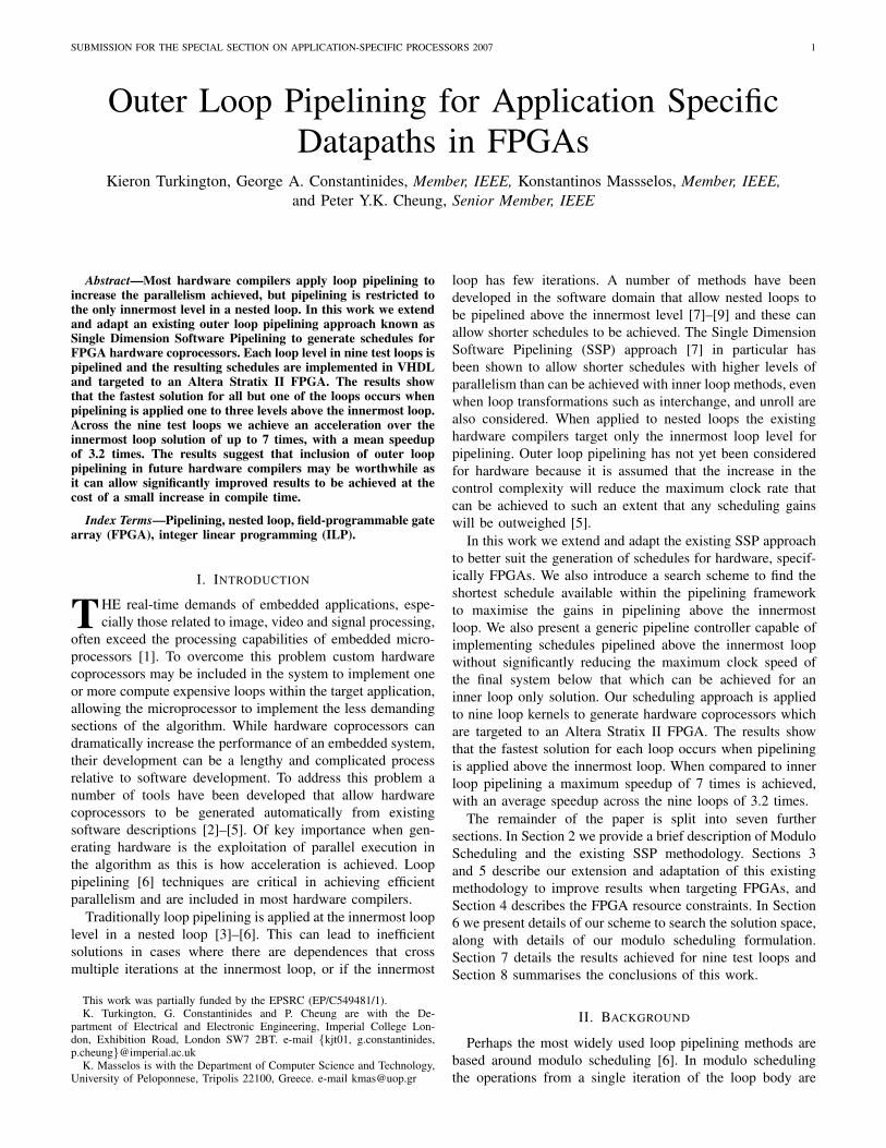
Fig. 5. The ‘Incrementer’ blocks used by the circuit in Figure 4 to update the loop indices. The bold bus lines are of width log2N , where N is the number ofloop iterations at the given loop level (a) The ‘Incrementer’ for the innermost loop level (b) The ‘Incrementer’ for all loop levels between the innermostlevel and the pipelined level (a) The ‘Incrementer’ for the pipelined loop level
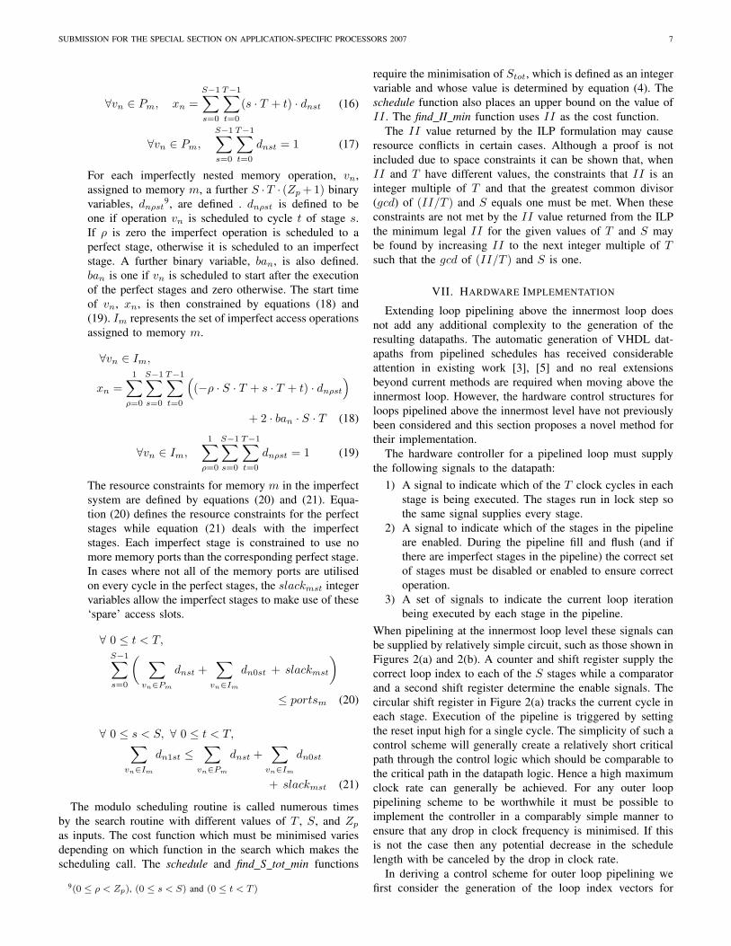
logic controlling the enable signals for a pipeline with onlyperfectly nested stages is shown in Figure 6 and Figure 7. Theexternsions to deal with imperfect nesting are relatively simple,requiring just additional shift registers and a small umber oflgoic gates, but these are not detailed here for brevity. At thepipeline reset the enable signal for stage 0 is set high to beginthe execution of the first iteration of the loop. The ‘1’ is shiftedthrough the register enabling each stage in turn. There is afeedback path from stage S − 1 to stage 0 as each iterationat the pipelined loop level entails more than one iteration ofthe innermost loop and so a single stage must remain enabled.The initial values for the index vectors will cause the ‘Inc top’signal to go high S−1 times as iterations 2 through S−1 (atthe pipelined level) begin their executions. This switches themultiplexer in Figure 6 so that an additional ‘1’ is input intothe shift register for each new iteration11, eventually enablingall S stages. The ‘Enable/Disable’ block, detailed in Figure 7,counts the number of ‘Inc top’ inputs received and, once all Sstages have been enabled, it switches its output to ‘0’. The nextoccasion when ‘Inc top’ goes high occurs when the pipelineflush begins at the end of the loop execution. As the final Siterations at the pipelined level end they again cause the indexvectors to overflow as they pass through the ‘incrementer’blocks, sending ‘Inc top’ high a further S times. This againswitches the multiplexer in Figure 6, but the output from the‘Enable/Disable’ block is now ‘0’ so increasing numbers ofstages are disabled. When the last iteration terminates the last‘1’ in the shift register will be replaced with a ‘0’ and alldatapath operations will terminate.
The hardware structures described will serve to control mostloops pipelined above the innermost loop level, but there arespecial cases where variations on the blocks presented must beused. Examples of this are when the number of loop iterationsat the pipelined level is less than the number of perfectlynested stages and when the initiation interval greater thanthe number of innermost loop iterations in a single iterationat the pipelined level. Although the details for these casescannot be detailed due to space constraints, they have beenconsidered and a small library of VHDL modules written tocover every possible combination of scheduling parameters (T ,S, II and Zp). The blocks are all parameterised and a simple
11The output of the ‘Enable/Disable’ block is initially ‘1’ after the reset
0 1
Enable/Disable Shift Reg
Reset Reset Cycle[T-1] Enable
Out In
Reset > >
Clock Cycle[T-1]
enables[S-1]
enables[S-2..0]
en[S-1]
en[S-2..0]
Inc_top
Inc_top
Fig. 6. The logic to control the enable signal for each pipeline stage. The‘Enable/Disable’ block is detailed in Figure 7. The ‘Shift Reg’ block is a shiftregister with S bits. ‘en[0]’ is the output from the first register in the chain.‘en[S-1]’ is the output from the last register in the chain. At the reset ‘en[0]’is set to ‘1’ while all other bits are set to ’0’. The ‘Inc top’input is connectedto the ‘Inc out’ from the ‘Incrementer’ block at the pipelined loop level
Counter
> Enable CT = 1 CT = 0
CT
A
B A=B
Comparator
Inc_top
Reg
D Q
> Enable
0 1
Cycle[T-1]
Reset
Clock
Out S-1
0 1
Fig. 7. The ‘Enable/Disable’ block. The ‘Inc top’input is connected to the‘Inc out’ from the ‘Incrementer’ block at the pipelined loop level
tool has been developed to instantiate the correct blocks withthe correct generic values to automatically generate a pipelinecontroller for the given values of T , S, II and Zp.
VIII. RESULTS
Our extended Single Dimension Software Pipelining algo-rithm has been used to pipeline each level in nine nestedloops. The pipelined data path for each loop level is imple-mented manually in VHDL based on the schedule producedby our tool. The VHDL for the pipeline controller for eachcase is generated automatically by our scheduling tool fromthe set of parameterised component blocks described in theprevious section. Four of the loops use a fixed point numberrepresentation in their datapaths. These are an image edgedetection kernel, a full search motion estimation kernel, acomplex fast Fourier transform (FFT) and a two dimensionalmedian filter. The remaining five loops have floating pointdatapaths. These are a matrix-matrix multiply kernel, a 2D hy-drodynamics fragment taken from the Livermore Loops [16],a successive over relaxation kernel (SOR) [17], the MINRES

SUBMISSION FOR THE SPECIAL SECTION ON APPLICATION-SPECIFIC PROCESSORS 2007 10
TABLE ISCHEDULING RESULTS FOR THE EDGE DETECTION (ED), MOTION ESTIMATION (ME), FAST FOURIER TRANSFORM (FFT) AND MEDIAN FILTER (MED)
KERNELS. THE SPEEDUP FIGURE IS RELATIVE TO THE SCHEDULE LENGTH OBTAINED WHEN THE INNERMOST LOOP IS PIPELINED . THE AVERAGEPARALLELISM IS THE RATIO OF THE COMPLETELY SEQUENTIAL SCHEDULE LENGTH TO THE PIPELINED SCHEDULE LENGTH
Loop Level S T II Zp Cycles Average SpeedupParallelism
ED 4 3 2 2 0 1,935,480 2.40 1.000ED 3 3 2 2 0 1,419,352 3.27 1.364ED 2 3 2 2 1 1,297,432 3.68 1.492ED 1 3 2 2 1 1,295,408 3.69 1.494ME 6 3 2 2 0 3,686,400 3.55 1.000ME 5 4 2 2 0 3,315,200 3.95 1.112ME 4 5 2 2 0 3,287,040 3.99 1.121ME 3 5 2 2 0 3,278,848 3.99 1.124ME 2 4 2 2 1 3,277,536 3.99 1.125ME 1 4 2 2 1 3,277,326 3.99 1.125FFT 3 2 8 8 0 41,040 4.14 1.000FFT 2 2 8 4120 0 45,272 3.75 0.906
MED 5 3 2 2 0 49,152,000 3.03 1.000MED 4 5 1 6 1 35,717,120 5.63 1.376MED 3 5 1 476 1 164,429,824 1.01 0.299MED 2 8 1 1 1 21,368,576 7.75 2.300MED 1 8 1 1 1 21,364,751 7.75 2.301
TABLE IISCHEDULING RESULTS FOR THE MATRIX-MATRIX MULTIPLY (MMM), HYDRODYNAMICS (HD), SUCCESSIVE OVER RELAXATION (SOR), MINRES
(MIN) AND LU DECOMPOSITION (LU) KERNELS. THE SPEEDUP FIGURE IS RELATIVE TO THE SCHEDULE LENGTH OBTAINED WHEN THE INNERMOSTLOOP IS PIPELINED. THE AVERAGE PARALLELISM IS THE RATIO OF THE COMPLETELY SEQUENTIAL SCHEDULE LENGTH TO THE PIPELINED SCHEDULE
LENGTH
Loop Level S T II Zp Cycles Average SpeedupParallelism
MMM 3 3 7 2 0 7,014,000,000 2.42 1.000MMM 2 8 2 2 1 2,002,030,000 8.49 3.503MMM 1 8 2 2 1 2,002,000,030 8.49 3.503
HD 2 8 6 42 0 42,006,000 1.95 1.000HD 1 8 6 42 0 6,000,294 13.67 7.001
SOR 3 3 7 7 0 7,014,000 2.71 1.000SOR 2 20 2 2 1 2,002,078 9.51 3.503MIN 3 4 7 7 0 7,021,000 2.42 1.000MIN 2 25 2 8 1 2,002,242 8.50 3.507LU 3 6 3 3 0 1,010,524,464 5.95 1.000LU 2 6 3 3 1 1,008,291,933 5.97 1.002LU 1 9 2 36050 1 678,002,026 8.88 1.49
algorithm [18] and an LU decomposition kernel [19]. The edgedetection, motion estimation and median filter algorithms actupon 256x256 pixel images (8 bit fixed point). The searchwindow for the motion estimator is +/-2 pixels and the medianfilter operates over a 5x5 pixel window. The matrix multiply,hydrodynamics, successive over relaxation, MINRES and LUdecomposition kernels operate on 1000x1000 element (singleprecision) floating point matrices. The outermost loop (level1) in the MINRES and SOR kernels is not pipelined as it isa while loop in both cases and the number of iterations isnot fixed. For each case it is assumed that all of the imageor matrix data accessed by the loop is stored in one bankof single port off-chip SRAM. An exception is made forthe hydrodynamics kernel where it is assumed that five large
matrices used are split across two banks of SRAM.
The scheduling results for each level in the four fixed pointtest loops are detailed in Table I and the results for the fivefloating point loops are detailed in Table II. In every case, asidefrom the FFT example, pipelining above the innermost looplevel does yield a shorter schedule. The FFT kernel has a longloop carried dependence at the outer loop level and so there isno advantage in pipelining above the innermost loop. However,since the pipelining methodology presented also considers theinnermost loop, no performance is lost compared to an inner-loop-only methodology. While this is of interest, the originalSingle Dimension Software Pipelining work [7] has alreadydemonstrated the benefits of extending pipelining above theinnermost loop. However, the results also demonstrate that our
SUBMISSION FOR THE SPECIAL SECTION ON APPLICATION-SPECIFIC PROCESSORS 2007 11
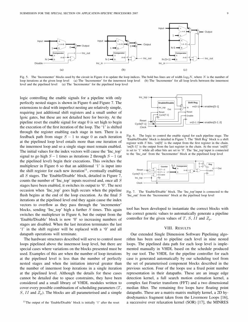
TABLE IIIHARDWARE IMPLEMENTATION RESULTS FOR THE TEST LOOPS. THE SPEEDUP FIGURE IS RELATIVE TO THE INNERMOST LOOP SOLUTION. ALUTS
(ADAPTIVE LOOKUP TABLES) ARE THE BASIC CONFIGURABLE ELEMENTS IN THE STRATIX II FAMILY OF FPGAS
Loop Level ALUTs Registers Fmax Cycles Time Speedup(MHz) (s)
ED 4 124 108 457 2,129,028 0.0046 1.000ED 3 127 110 438 1,548,384 0.0035 1.318ED 2 266 181 431 1,297,940 0.0030 1.533ED 1 288 233 399 1,295,410 0.0032 1.439ME 6 91 142 489 3,891,200 0.0080 1.000ME 5 115 163 483 3,328,000 0.0069 1.154ME 4 191 271 347 3,289,600 0.0306 0.839ME 3 205 281 335 3,279,360 0.0318 0.813ME 2 305 269 384 3,277,568 0.0245 0.932ME 1 326 280 406 3,277,328 0.0242 0.985
MED 5 51 58 500 52,428,800 0.1049 1.000MED 4 163 216 500 36,372,480 0.0727 1.441MED 2 243 474 496 21,369,088 0.0431 2.434MED 1 317 539 500 21,364,753 0.0427 2.453MMM 3 834 847 246 7,016,000,000 28.52 1.000MMM 2 1067 1307 250 2,002,032,000 8.01 3.554MMM 1 1175 1360 252 2,002,000,032 7.94 3.590
HD 2 3957 4449 233 42,008,000 0.180 1.000HD 1 4088 4451 233 6,000,296 0.026 7.001
SOR 3 812 719 236 7,016,000 0.030 1.000SOR 2 4600 8779 210 2,002,080 0.010 3.118MIN 3 2445 4569 241 7,023,000 0.029 1.000MIN 2 4071 7403 210 2,002,244 0.010 3.056LU 3 805 1029 223 1,011,527,460 4.536 1.000LU 2 1254 1722 219 1,008,293,931 4.604 0.985LU 1 3156 4959 216 678,002,028 3.139 1.444
extensions to the SSP methodology can offer gains over theexisting work. For example, when pipelining loop level 1 ofthe hydrodynamics kernel the optimum stage length is foundto be 6 while the initiation interval is 42. If T were forced totake the same value as II the minimum stage length would be42, leading to a schedule that is seven times longer than thatpresented here. The results for the motion estimation kerneldemonstrate the potential benefit of searching the availablesolution space. For loop level 5 the minimum number of stageswhen T is minimised is 3. With 3 stages in the pipelinethe minimum II of 2 cycles may also be achieved, so 3stages appears to be optimal. However, the scheduling searchincreases S to 4 stages as there are 16 iterations at thepipelined level and making S a factor of Np minimises theschedule length. When levels 3 and 4 are pipelined the numberof perfect stages in first increased to 4 to accommodate extraimperfectly nested instructions (allowing Zp to be zero), andthen increased to five so that it is again a factor of Np (whichis 5 in both cases).
Table III details the performance results for eight of the testloops when the pipelined hardware accelerator for each looplevel is targeted to an Altera Stratix II FPGA, specifically anEP2S15 part of the fastest speed grade (C3). The hardwareaccelerator has not been implemented for either loop level ofthe FFT as there are no scheduling gains in moving to the outerloop. Likewise, the hardware accelerator for pipelining at level
3 in the median filter has not been implemented as it offersno gains over the inner loop. Only the control and datapathoperations from the levels up to and including the pipelinedloop level are targeted to the FPGA, with the remaining looplevels executed on a host microprocessor. The design of thepipeline controller is such that two clock cycles are required toinitialise the pipeline each time it is called by the host system.The additional cycles have been added to the schedule lengthsin Table I and Table II to produce those shown in Tables IIIrespectively. For each loop level the time taken for schedulingwas less then 10 seconds, with most completing in less than 1second, which may be considered negligible when comparedto the minutes taken for synthesis and place and route.
The results in Table III show that, in all eight cases, theoptimum (fastest) solution occurs when pipelining above theinnermost loop. However, we notice that the fastest implemen-tation does not usually coincide with the shortest scheduleas there is some degradation in the clock frequency of thepipelines as we move towards the outermost loop. In everycase the fastest implementation occurs one or two loop levelsabove the innermost loop as this these levels offer the besttradeoff between the scheduling gains and the clock frequency.This is contrary to the claims in existing work that extendingpipelining above the innermost is rarely worthwhile [5].
The degradation in the maximum clock frequency variesacross the eight implemented loops. The edge detection data-
SUBMISSION FOR THE SPECIAL SECTION ON APPLICATION-SPECIFIC PROCESSORS 2007 12
path is a small, simple circuit and so the critical path throughthe complete design lies within the controller. Hence we seea steady decline in the clock frequency as the pipelining levelmoves up through the loop and the controller becomes morecomplex. The motion estimator also has a relatively simpledatapath and so the critical path for levels 5 and 6 againlies within the controller. There is a sharp drop in the clockrate as we move up to levels 3 and 4, but this is not dueto the controller. Levels 3 and 4 require the implementationof imperfectly nested operations which increase the datapathcomplexity, moving the critical path into the datapath. Whenlevels 1 and 2 are pipelined the imperfect operations arescheduled differently and this reduces the length of the criticalpath, allowing the clock rate to increase above that achievedfor levels 3 and 4. The arithmetic units in the floating pointimplementations form the critical path in each case and sothere is virtually no degradation in clock frequency for theseloops.
There is an increase in FPGA resource usage as pipeliningmoves towards the outermost loop. For simple circuits such asthe edge detector and the motion estimator the fastest solutionhas an ALUT and register usage roughly double that for theinnermost loop. This is because the edge detector and motionestimator have datapaths that are relatively small and thereforecomparable to the size of the controller. Hence a significantincrease in the size of the controller leads to a significantincrease in the overall resource usage. The more complexdatapaths of the matrix multiplication and hydrodynamicskernels lead to less noticeable increases in the resource usageas we move towards the outer loops. In fact, for both the matrixmultiplication and hydrodynamics examples, the increase inresource usage when moving to the outer loop is less thanwould be expected bearing in mind the extra level of controladded. This is most likely due to the heuristic nature ofthe optimisation algorithms used during the place and routeprocess to map the design to the FPGA. These optimisationsmay duplicate logic and/or registers to increase the clock rateachieved, and this process may mask any actual increase inresource usage if the increase is small relative to the total. Theincreased resource usage for the outer loops of the MINRES,SOR and LU decomposition examples is mainly due to theinclusion of extra imperfectly nested floating point operations.In every case the designer must decide whether the increase inspeed achieved in pipelining at an outer loop level is necessary,or warrants the extra resource usage incurred.
While it has been shown that outer loop pipelining canoffer advantages over the direct implementation of inner looponly methods, the role of loop interchange has not yet beenconsidered. The matrix multiplication example has a loopcarried dependence at the inner loop level that forces aninitiation interval of 7 cycles when pipelining the innermostloop. However, there are no dependences at the outer looplevels, so interchanging either of the two outer levels to theinnermost loop and then pipelining will leave the initiationinterval bound only by the resource constraints, as is thecase when pipelining above the innermost loop. So whatadvantage does our approach offer over interchange and innerloop pipelining? Firstly, as pointed out in [7], some loops
may not be interchanged due to dependences. Also, as withthe hydrodynamics kernel, it is possible for there to be loopcarried dependences at all loop levels. In the case of thehydrodynamics kernel the initiation interval will be 42 cycles,no matter how the loop is interchanged. Hence interchange andinner loop pipelining will produce a solution that is roughly7 times slower than our approach.
Another advantage of the approach presented here is theability to deal with imperfectly nested operations, especiallyimperfectly nested memory accesses. If there are operationsnested imperfectly at any level which we wish to interchangeto the innermost loop, these operations must be moved intothe innermost loop (and their executions guarded against). Thismay force a larger number of stages in the pipeline than ourapproach can offer. It may also force a larger stage length ifthe operations are memory accesses since the minimum stagelength (T ) is determined by the numbers of perfectly nestedaccesses to each memory. The matrix multiplication is a goodexample of this as there is a write to the external memorynested above the innermost loop. Interchanging either outerloop to the inner loop will force this write into the inner mostloop and increase the minimum T from 2 to 3 cycles, reducingthe speed of the final solution to roughly two thirds of thatoffered by our approach.
Two other potential advantages of our approach over in-terchange and inner loop pipelining are the reduction in thenumber of cycles spent flushing and filling the pipeline andthe potential for data reuse. All of the speedup gained inthe motion estimation example is gained because the outerloop pipelines are filled and flushed less frequently. In theLU decomposition example we are able to buffer a columnof matrix data on chip when the outer loop is pipelined. Thisreduces the number of perfectly nested memory accesses tothe external memory from 3 to 2 per iteration, allowing aminimum T of 2 cycles instead of 3.
While our approach can offer advantages over interchangecombined with inner loop pipelining, that does not mean thatloop interchange has no role in improving results achievedwhen pipelining above the innermost loop. However, thepotential gains of combining loop interchange and outer looppipelining in hardware have not yet been considered and this isleft as future work. It should be noted however that interchangewas considered in combination with outer loop pipelining inthe original SSP work [7] and was shown to be of benefit.
IX. CONCLUSION
In this work an existing methodology for pipelining softwareloops above the innermost loop level has been adapted foruse in generating FPGA based hardware coprocessors. Theexisting Single Dimension Software Pipelining approach hasbeen extended to allow the initiation interval and stage lengthof a pipeline to take different values, offering an improvementin performance of 7 times in one example. We have also intro-duced a simplified method for dealing with imperfectly nestedinstructions that reduces control complexity. Furthermore, asearch of the scheduling space has been developed such thatthe schedule with the shortest execution time (in clock cycles)is found.
SUBMISSION FOR THE SPECIAL SECTION ON APPLICATION-SPECIFIC PROCESSORS 2007 13
Our scheduling tool has been applied to nine test loops.In all but one case, when the resulting coprocessors aretargeted to an Altera Stratix II FPGA, the fastest solution isfound when the loop is pipelined one to three levels abovethe innermost loop. While there may be degradation in theclock frequency of the resulting hardware when pipeliningis extended above the innermost loop, the decreases in theschedule length have been shown to outweigh this factor.As a result we achieved speedups over the innermost loopsolution ranging from 1 (no speedup) to 7 times, with anaverage (root-mean-square) speedup of 3.22 times. Theseresults indicate that, while pipelining above the innermost loopmay not provide significant gains in every case, adding thiscapability to the toolbox of transformations used by hardwarecompilers could certainly be of use in exploiting parallelismin hardware coprocessors. This seems especially true whentargeting floating point kernels as the long latencies of the(normally) deeply pipelined arithmetic units can lead to longloop carried dependences and large initiation intervals.
REFERENCES
[1] B. Hounsell and R. Taylor, “Co-processor Synthesis: A New Method-ology for Embedded Software Acceleration,” in Proc. Conf. Design,Automation and Test in Europe, 2004, pp. 682–683.
[2] Nios II C2H Compiler User Guide, Altera Corp., 2007.[3] Z. Guo, B. Buyukkurt, and W. Najjar, “Optimized Generation of Data-
path from C Codes for FPGAs,” in Proc. Design Automation and Testin Europe, 2005, pp. 112–117.
[4] Catapult C Datasheet, Mentor Graphics, 2006.[5] M. Weinhardt and W. Luk, “Pipeline Vectorization for Reconfigurable
Systems,” in Proc. IEEE Symp. FPGAs for Custom Computing Ma-chines, 1999, pp. 52–62.
[6] V. Allan, R. Jones, R. Lee, and S. Allan, “Software Pipelining,” ACMProc. Computing Surveys, vol. 27, no. 3, pp. 367–432, 1995.
[7] H. Rong, Z. Tang, R. Govindarajan, A. Douillet, and G. Gao, “Single-Dimension Software Pipelining for Multi-Dimensional Loops,” in Proc.IEEE Int. Symp. Code Generation and Optimization, 2004, pp. 163–174.
[8] J. Wang and B. Su, “Software Pipelining of Nested Loops for Real-time DSP Applications,” in Proc. IEEE Int. Conf. Acoustics, Speechand Signal Processing, 1998, pp. 3065–3068.
[9] T. Yu, Z. Tang, C. Zhang, and J. Luo, “Control Mechanism forSoftware Pipelining on Nested Loop,” in Proc. Advances in Paralleland Distributed Computing, 1997, pp. 345–350.
[10] W. Pugh, “Definitions of Dependence Distance,” ACM Letters on Pro-gramming Languages and Systems, vol. 1, no. 3, pp. 261–265, 1992.
[11] R. Ramakrishna, “Iterative Modulo Scheduling,” Hewlett Packard Lab-oratories, Tech. Rep. HPL-94-115 , 1995.
[12] Statix II Device Handbook, Altera Corp., 2007.[13] M. Weinhardt and W. Luk, “Memory Access Optimization for Recon-
figurable Systems,” IEE Proc. Computers and Digital Techniques, vol.148, no. 3, pp. 105–112, 2001.
[14] H. Rong, Z. Tang, R. Govindarajan, A. Douillet, and G. Gao, “Single-Dimension Software Pipelining for Multi-Dimensional Loops,” Univer-sity of Delaware, Tech. Rep. CAPSL Technical Memo 049, 2005.
[15] H. Williams, Model Building in Mathematical Programming (FourthEdition). Wiley, 1998.
[16] F. McMahon, “The Livermore Fortran Kernels Test of the NumericalPerformance Range,” Performance Evaluation of Supercomputers, pp.143–186, 1988.
[17] A. Hadjidimos, “Successive Over Relaxation (SOR) and related meth-ods,” Journal of Computational and Applied Mathematics, vol. 123, no.1-2, pp. 177–199, 2000.
[18] R. Barrett, M. Berry, T. F. Chan, J. Demmel, J. Donato, J. Dongarra,V. Eijkhout, R. Pozo, C. Romine, and H. V. der Vorst, Templates for theSolution of Linear Systems: Building Blocks for Iterative Methods, 2ndEdition. SIAM, 1994.
[19] S. Grossman, Elementary Linear Algebra (Fourth Edition). SaundersCollege Publishing, 1994.
Kieron Turkington received the M.Eng (Hons)degree in Electrical and Electronic Engineering fromImperial College London, U.K., in 2005. He iscurrently a PhD student in the Circuits and Systemsresearch group at Imperial College London, with re-search interests based around behavioural synthesisand memory optimisations for FPGAs.
George A. Constantinides (S96-M01) received theM.Eng. (Hons) in Information Systems Engineeringand the Ph.D. degree from Imperial College London,London, U.K., in 1998 and 2001, respectively. In2002, he joined the faculty at Imperial CollegeLondon and is currently a Senior Lecturer.
Dr. Constantinides is a member of the IEEE, theACM, and SIAM. He is associate editor of theIEEE Transactions on Computers and the Journalof VLSI Signal Processing. He was programmeco-chair of the IEEE International Conference on
Field-Programmable Technology in 2006 and Field Programmable Logic andApplications in 2003, and serves on the technical program committees ofseveral conferences, including DATE, where he is chair of the ArchitecturalSynthesis track in 2009.
Kostantinos Masselos (S92-M94) received a firstdegree in Electrical Engineering from University ofPatras, Greece in 1994 and an MSc degree in VLSISystems Engineering from University of Manch-ester Institute of Science and Technology, UnitedKingdom in 1996. In April 2000 he got a PhDdegree in Electrical and Computer Engineering fromUniversity of Patras, Greece.
From 1997 until 1999 he was associated as avisiting researcher with the Inter-university MicroElectronics Centre (IMEC) in Leuven, Belgium,
where he was involved in research related to the ACROPOLIS multimediacompiler. Until 2004 he was with INTRACOM S.A, Greece where he wasinvolved in the realization of wireless communication systems. In 2005 hejoined as a lecturer the Department of Electrical Engineering and Electronicsof Imperial College London. Since 2006 he is an Assistant Professor inthe Department of Computer Science and Technology of University ofPeloponnese, Greece and a visiting lecturer at Imperial College. His maininterests include compiler optimizations and high level synthesis, high levelpower optimization, FPGAS and reconfigurable hardware, and efficient im-plementations of DSP algorithms. He is a member of the IEEE.
Peter Y.K. Cheung (M85-SM04) received the B.S.degree with first class honors from Imperial Collegeof Science and Technology, University of London,London, U.K., in 1973. Since 1980, he has beenwith the Department of Electrical Electronic Engi-neering, Imperial College, where he is currently aProfessor of digital systems and deputy head of thedepartment. He runs an active research group in dig-ital design, attracting support from many industrialpartners. Before joining Imperial College he workedfor Hewlett Packard, Scotland. His research interests
include VLSI architectures for signal processing, asynchronous systems,reconfigurable computing using FPGAs, and architectural synthesis.
Prof. Cheung was elected as one of the first Imperial College TeachingFellows in 1994 in recognition of his innovation in teaching.
Copyright © 2022 FDOKUMEN