Orientation of charged clay nanotubes in evaporating droplet meniscus
10
Orientation of charged clay nanotubes in evaporating droplet meniscus Yafei Zhao a , Giuseppe Cavallaro b , Yuri Lvov a,c,⇑ a Institute for Micromanufacturing, Louisiana Tech University, Ruston, USA b Department of Physics and Chemistry, University of Palermo, Italy c Kazan Federal University, Tatarstan, Russian Federation article info Article history: Received 19 September 2014 Accepted 16 October 2014 Available online 4 November 2014 Keywords: Halloysite nanotubes Alignment Droplet evaporation Coffee ring Liquid crystal abstract During drying, an aqueous suspension of strongly charged halloysite clay nanotubes concentrates at the edge of the droplet (‘‘coffee-ring’’ effect) which provides alignment of the tubes along the liquid-substrate contact line. First, the surface charge of the nanotubes was enhanced by polyanion adsorption inside of the lumen to compensate for the internal positive charges. This increased the magnitude of the n-poten- tial of the tubes from 36 to 81 mV and stabilized the colloids. Then, colloidal halloysite was dropped onto the substrate, dried at 65 °C and after a concentration of 0.05 mg mL 1 was reached, the alignment of nanotubes occurred starting from the droplet edges. The process was described with Onsager’s theory, in which longer nanorods, which have higher surface charge, give better ordering after a critical concen- tration is reached. This study indicates a new application of halloysite clay nanotubes in polymeric com- posites with anisotropic properties, microchannel orientation, and production of coatings with aligned nanotubes. Ó 2014 Elsevier Inc. All rights reserved. 1. Introduction The self-assembly of nanoparticles is a perspective route to developing devices that exploit the properties of anisotropic mate- rials properties, ranging from electronics to biomaterials. The con- trolled assembly of elongated particles such as carbon nanotubes, ZnO and DNA nanowires allows for their preferential alignment along a spatial direction [1–4]. This process enhances the electrical, electrochemical, optical and electromechanical properties along the orientation line [2,5–8]. Nano-fibers and tubes organize into ordered structures either through external stimuli or interparticle interactions; electrical, magnetic or mechanical forces, and liquid flow can induce the ordering [2,5,6,9–13]. Most of the methods based on external forces require specialized equipment and they are limited in their ability to fabricate uniformly aligned nano- structures over a large area. On the other hand, self-assembly can be achieved by specific interactions between the nano-objects as is used in spin coating, inject printing and drop casting [8,9,14– 18]. Recently, evaporation-induced self-assembly on solid surfaces has received attention due to the ease of fabricating highly orga- nized structures [14–17]. Drying a droplet of nanoparticle disper- sion drives the formation of ordered patterns on the substrate, which depends on the mode of solvent evaporation [17]. The pat- tern that is formed is often a ring-like deposit (‘‘coffee ring’’) along the edge of the initial droplet. In the absence of Marangoni flow and natural convection during evaporation, when the contact line of the drying droplet is pinned, there is an outward and radial hydrodynamic flow that prevents shrinkage of the droplet, which would replenish the liquid evaporating from the edge [17,19]. This flow carries the suspended particles from the center to the droplet periphery, causing the formation of a dense ring-like deposition. When a critical colloid concentration is reached the anisotropic particles near the edge transition from the isotropic to the liquid crystal phase and align parallel to the edge, as was observed for carbon nanotubes [14,20], gold [21] and iron oxide [22] nanoparti- cles. The explanation for this phenomenon is based on the classic Onsager’s theory of high aspect ratio rigid rods forming orientation and position ordered liquid crystalline phases [1,23]. A recent review [17] reported that the droplet-casting method was success- fully used for the self-assembly of polymers, proteins, graphene and nanoparticles, such as carbon nanotubes and metal oxides. No results were yet reported for nanoclays, which are appealing natural materials for environmental friendly composites. Among the clays, halloysite is interesting for applications because of its large surface area, tunable surface chemistry and hollow tubular morphology [24,25]. Halloysite clay, which is rolled kaolinite sheets, has a tubular shape with different external and internal surface chemistry and http://dx.doi.org/10.1016/j.jcis.2014.10.050 0021-9797/Ó 2014 Elsevier Inc. All rights reserved. ⇑ Corresponding author at: Institute for Micromanufacturing, Louisiana Tech University, Ruston, USA. E-mail address: [email protected] (Y. Lvov). Journal of Colloid and Interface Science 440 (2015) 68–77 Contents lists available at ScienceDirect Journal of Colloid and Interface Science www.elsevier.com/locate/jcis
Transcript of Orientation of charged clay nanotubes in evaporating droplet meniscus

Journal of Colloid and Interface Science 440 (2015) 68–77
Contents lists available at ScienceDirect
Journal of Colloid and Interface Science
www.elsevier .com/locate / jc is
Orientation of charged clay nanotubes in evaporating droplet meniscus
http://dx.doi.org/10.1016/j.jcis.2014.10.0500021-9797/� 2014 Elsevier Inc. All rights reserved.
⇑ Corresponding author at: Institute for Micromanufacturing, Louisiana TechUniversity, Ruston, USA.
E-mail address: [email protected] (Y. Lvov).
Yafei Zhao a, Giuseppe Cavallaro b, Yuri Lvov a,c,⇑a Institute for Micromanufacturing, Louisiana Tech University, Ruston, USAb Department of Physics and Chemistry, University of Palermo, Italyc Kazan Federal University, Tatarstan, Russian Federation
a r t i c l e i n f o a b s t r a c t
Article history:Received 19 September 2014Accepted 16 October 2014Available online 4 November 2014
Keywords:Halloysite nanotubesAlignmentDroplet evaporationCoffee ringLiquid crystal
During drying, an aqueous suspension of strongly charged halloysite clay nanotubes concentrates at theedge of the droplet (‘‘coffee-ring’’ effect) which provides alignment of the tubes along the liquid-substratecontact line. First, the surface charge of the nanotubes was enhanced by polyanion adsorption inside ofthe lumen to compensate for the internal positive charges. This increased the magnitude of the n-poten-tial of the tubes from �36 to �81 mV and stabilized the colloids. Then, colloidal halloysite was droppedonto the substrate, dried at 65 �C and after a concentration of �0.05 mg mL�1 was reached, the alignmentof nanotubes occurred starting from the droplet edges. The process was described with Onsager’s theory,in which longer nanorods, which have higher surface charge, give better ordering after a critical concen-tration is reached. This study indicates a new application of halloysite clay nanotubes in polymeric com-posites with anisotropic properties, microchannel orientation, and production of coatings with alignednanotubes.
� 2014 Elsevier Inc. All rights reserved.
1. Introduction
The self-assembly of nanoparticles is a perspective route todeveloping devices that exploit the properties of anisotropic mate-rials properties, ranging from electronics to biomaterials. The con-trolled assembly of elongated particles such as carbon nanotubes,ZnO and DNA nanowires allows for their preferential alignmentalong a spatial direction [1–4]. This process enhances the electrical,electrochemical, optical and electromechanical properties alongthe orientation line [2,5–8]. Nano-fibers and tubes organize intoordered structures either through external stimuli or interparticleinteractions; electrical, magnetic or mechanical forces, and liquidflow can induce the ordering [2,5,6,9–13]. Most of the methodsbased on external forces require specialized equipment and theyare limited in their ability to fabricate uniformly aligned nano-structures over a large area. On the other hand, self-assembly canbe achieved by specific interactions between the nano-objects asis used in spin coating, inject printing and drop casting [8,9,14–18]. Recently, evaporation-induced self-assembly on solid surfaceshas received attention due to the ease of fabricating highly orga-nized structures [14–17]. Drying a droplet of nanoparticle disper-sion drives the formation of ordered patterns on the substrate,
which depends on the mode of solvent evaporation [17]. The pat-tern that is formed is often a ring-like deposit (‘‘coffee ring’’) alongthe edge of the initial droplet. In the absence of Marangoni flowand natural convection during evaporation, when the contact lineof the drying droplet is pinned, there is an outward and radialhydrodynamic flow that prevents shrinkage of the droplet, whichwould replenish the liquid evaporating from the edge [17,19]. Thisflow carries the suspended particles from the center to the dropletperiphery, causing the formation of a dense ring-like deposition.When a critical colloid concentration is reached the anisotropicparticles near the edge transition from the isotropic to the liquidcrystal phase and align parallel to the edge, as was observed forcarbon nanotubes [14,20], gold [21] and iron oxide [22] nanoparti-cles. The explanation for this phenomenon is based on the classicOnsager’s theory of high aspect ratio rigid rods forming orientationand position ordered liquid crystalline phases [1,23]. A recentreview [17] reported that the droplet-casting method was success-fully used for the self-assembly of polymers, proteins, grapheneand nanoparticles, such as carbon nanotubes and metal oxides.No results were yet reported for nanoclays, which are appealingnatural materials for environmental friendly composites. Amongthe clays, halloysite is interesting for applications because of itslarge surface area, tunable surface chemistry and hollow tubularmorphology [24,25].
Halloysite clay, which is rolled kaolinite sheets, has a tubularshape with different external and internal surface chemistry and

Y. Zhao et al. / Journal of Colloid and Interface Science 440 (2015) 68–77 69
high aspect ratio of about 10–30. The sizes of halloysite nanotubes(HNTs) are within 600–1500 nm in length, 10–20 nm in innerdiameter, and 50–60 nm in outer diameter depending on thedeposit and milling process. Halloysite has a positive alumina innerlumen and a negative silica outer surface allowing its selectivefunctionalization [26,27] and the encapsulation of chemically andbiologically active compounds [24,25,28]. The toxicity of halloysitenanotubes was analyzed for human breast cells and human epithe-lial adenocarcinoma cells [29]. The viability of the halloysite-trea-ted cells (up to 0.5 mg mL�1) was preserved (up to 70% of viablecells), however, at higher concentrations of HNTs, cell death wasinduced. A low toxicity of chitosan-based scaffolds for tissue engi-neering was also demonstrated by monitoring the growth of fibro-blasts on nanocomposites [30]. No significant effects of fibroblastsattachment and development on chitosan-doped scaffold wereobserved. Therefore, halloysite is considered as safe for very highconcentration up 1 mg mL�1 of cell culture or tissue. These proper-ties lead to halloysite application in functional polymeric compos-ites with controlled release of anticorrosion, antimicrobial andflame-retardant agents and for wastewater treatment[24,25,28,31–36]. Halloysite can be dispersed in aqueous solutionsby modifying the inner lumen with anionic surfactants to greatlyenhance the surface charge of the nanotubes [26,27]. Halloysitecan form liquid crystalline phases when dispersed in aqueous solu-tion [37].
Here we present a strategy to produce aligned halloysite struc-tures by using evaporation-induced droplet-casting method. Thenanotubes cavity was functionalized with poly(styrene sulfonate)to enhance its surface charge resulting in high colloidal stabilitywhich allows for the halloysite orientational self-assembly. Theinfluence of the nanotubes length, charge and the concentrationon orientation was analyzed. Onsager’s theory and ‘‘coffee-ring’’phenomenon were employed to explain the alignment self-assem-bly of halloysite nanotubes.
2. Experimental and methods
2.1. Materials
Two types of halloysite nanotubes with different lengths wereselected to observe the orientation phenomenon: halloysite withshorter length of ca 0.6 lm and length/diameter ratio of ca 15which underwent to two-step milling was obtained from AppliedMinerals Inc. (s-HNT), and none-milled pristine halloysite with fulllength of ca 1.5 lm and length/diameter ratio of ca 30 was pur-chased from China Henan Province (1-HNT). Polystyrene sulfonatesodium salt (PSS, MW 70,000) and sodium chloride (NaCl, 99.99%)were purchased from Sigma–Aldrich and were used without fur-ther treatments. Sodium hydroxide (NaOH, 1 M) and hydrochloricacid (HCl, 1 M), prepared from analytical grade chemicals werepurchased from Sigma–Aldrich and used for pH adjustments.
2.2. Preparation of PSS/HNTs hybrid for surface charge enhancing
2 g of PSS was dispersed in 100 mL of deionized water in a flaskand stirred for 30 min to form a homogenous suspension. Then, s-HNTs or l-HNTs (2 g) were added gradually under continuous stir-ring in this solution, magnetically stirred for 48 h at room temper-ature and left standing for 1 h to precipitate aggregates. Theindividual HNTs were dispersed in the bulk, while the impuritiesand aggregations precipitated at the flask bottom. The supernatantdispersion was collected and then centrifuged at 5000 rpm for10 min. The precipitated halloysite was washed 3–4 times withdeionized water until it became neutral. Finally, the obtained solidwas dried in a vacuum drier for 24 h and crushed into powder by
mortar before use. The samples were denoted as PSS/s-HNTs andPSS/l-HNTs, respectively.
2.3. Droplet-casting method
Pristine HNTs and PSS-functionalized HNTs aqueous dispersionswere prepared by adding HNTs, PSS/s-HNTs or PSS/l-HNTs intodeionized water and ultrasonicated with power level of 70 W pergallon for 5 min (the concentrations ranged from 0.01 to100 mg mL�1). These aqueous dispersions can be considered phys-ically stable because the n-potential of both pristine and function-alized halloysite is above 30 mV (in absolute value). The ‘‘droplet-drying’’ process was carried out by dropping 20–100 lL of the dis-persions onto a silicon wafer substrate and drying it at selectedtemperatures (25, 65, and 90 �C). Ionic force and pH of the disper-sions were changed by adding NaCl, NaOH and HCl, respectively.
2.4. Instrumentation
2.4.1. Zeta-potential and dynamic light scatteringn-potential and dynamic light scattering (DLS) measurements
were taken by using microelectrophoretic ZetaPlus Potential Ana-lyzer (Brookhaven Instruments) at 25.0 ± 0.1 �C. For this, dilutedaqueous dispersions of pristine and functionalized halloysite (ca.1 lg mL�1) were transferred into the special cell and electric fieldwas applied causing the movement of negatively charged nano-tubes toward cathode. n-potential of the particles was determinedby Smoluchowski formula. For all of the systems, the field-timeautocorrelation functions were well described by a mono-expo-nential decay process, which provides the rate (C) correlated withthe apparent diffusion coefficient Dt = C/q2, where q = 4pnk�1-
sin(h/2) is the scattering vector, being n the water refractive index,h the scattering angle (90�) and k the wavelength (632.8 nm).
2.4.2. ThermogravimetryExperiments were performed by using a TGA Q50 (TA Instru-
ments) under nitrogen flow of 25 cm3 min�1 for the sample and10 cm3 min�1 for the balance. The explored temperature intervalranged between 25 and 900 �C at a heating rate of 10 �C min�1.The loading of the polymer in the PSS/HNTs hybrid was deter-mined from the residual mass at 600 �C by taking into accountthe water content as reported in the literature [26,27].
2.4.3. Contact angleContact angle experiments were performed by using an optical
contact angle apparatus (OCA 20, Data Physics Instruments)equipped with a high-resolution CCD camera and a high-perfor-mance digitizing adapter. SCA 20 software (Data Physics Instru-ments) was used. For the study of the evaporation kinetics, asessile droplet (volume was 10.0 ± 0.5 lL) of modified halloysitedispersion was deposited on the silicon wafer substrate. The con-centration of the dispersion was 6 mg mL�1 and temperature25.0 ± 0.1 �C both for the support and the injecting syringe. Duringthe water evaporation, the evolution of the contact angle, contactradius and droplet volume were monitored. Images were collected25 times per second up to 15 min. The wettability of l-HNTs andPSS/l-HNTs solid pellets was also determined by measuring theirinitial contact angle with the sessile drop method.
2.4.4. Polarizing optical and scanning electron microscopiesThe orientational processes were investigated using an Olym-
pus BX-50 polarized light microscope under crossed polarizersduring a 360� rotation of the sample. Images were captured witha microscope-mounted digital camera (Olympus C-4000 Zoom).After drying the droplet on silicon wafer, it was mounted on a spec-imen holder (stub) glued with carbon tap for scanning electron

Table 1Physico-chemical properties of pristine and PPS modified halloysite (s – short and l –long), data error 5%.
Materials Dt � 1012
(m2 s�1)n-potential(mV)
Initial watercontact angle (�)
s-HNTs 1.1 �38 20PSS/s-HNTs 1.1 �81 20l-HNTs 1.2 �36 21PSS/l-HNTs 1.1 �64 21
70 Y. Zhao et al. / Journal of Colloid and Interface Science 440 (2015) 68–77
microscopy (SEM) observations in the secondary electron imagingmode by using HitachiS-4800 with an accelerating voltage of 3 kV.All the samples had been mildly annealed to reduce chargingeffects before being put into the SEM chamber. All SEM micro-graphs are related to the edge of the deposits.
3. Results and discussion
3.1. Functionalization of halloysite
The colloidal stability of nanoparticles dispersion plays a crucialrole on the efficiency of self-assembly by drop-casting [15]. Wefunctionalized halloysite tube lumen with an anionic polymer,which is selectively adsorbed on the positive alumina surface ofthe nanotube innermost due to electrostatic interactions. Specifi-cally, both long and short pristine halloysite nanotubes (1.5 lm l-HNTs and 0.5 lm s-HNTs) were modified with poly (styrene sulfo-nate) (PSS). The polymer loading was 5.1 ± 0.5 wt.%, which indi-cates that the nanotubes are almost fully filled with PSSconsidering that the halloysite lumen is ca. 10% of the tube hole.The addition of PSS does not change the surface wettability ofthe clay (Table 1) and pristine and inner-functionalized clay nano-tubes possess similar hydrophilicity. This finding proves the selec-tive modification of the halloysite inner surface (the presence ofPSS on the outer surface would determine an increase of the nano-particles’ hydrophobicity because of the polymer chains). More-over, Table 1 shows that the diffusion coefficient Dt of both shortand long nanotubes is not influenced by the PSS functionalizationindicating that the hybrids do not aggregate in agreement withthe absence of hydrophobic attractive interactions generated bythe chains of PSS. This makes the modified halloysite suitable forself-assembly by drop-casting. n-potential data revealed thatcharge of clay nanotubes is not influenced by their length, whilethe modification with PSS determined an increase of the net nega-tive charge. This result agrees with the entrapment of the anionicpolymer into the halloysite lumen and neutralization of its innerpositive charges. Similar findings were observed for anionic surfac-
Fig. 1. (a) Images of pristine and modified halloysite dispersion after 0 and 24 h. (b) SEsilicon substrate.
tants/HNTs hybrids [26,27]. Based on the Derjaguin and Landau,Verwey and Overbeek (DLVO) theory [38], the increase of halloy-site n-potential after the modification improves the colloidal stabil-ity of the nanorods because of the enhancement of the repulsiveinteractions. Both long and short pristine halloysite nanotubes (l-HNTs and s-HNTs) aqueous dispersions of 10 mg mL�1 started toprecipitate after 1 h, and almost all tubes sediment after 12 h, e.g.the original halloysite clay nanotube colloids were unstable(Fig. 1a). However, after modification with PSS, no halloysite pre-cipitation or aggregation occurred during the first hours and onlytiny sediment appeared after 24 h allowing for stable colloidal dis-persion for more than four weeks. SEM analysis of PSS/l-HNTsdroplet on silicon wafer after complete drying showed the highquality of the alignment at the droplet edge (Fig. 1b). This indicatedon the sufficient dispersion stability of PSS/HNTs for self-assembly.
3.2. Evaporation of halloysite droplet on substrate
Drops of isotropic phase of pristine and PSS-modified halloysitewere placed onto silicon substrate to study self-organized struc-tures of the nanotubes. Optical micrographs of dried droplets(Fig. 2a) indicate the formation of a ‘‘coffee-ring’’ deposit in theperiphery due to the outward capillary flow that occurs duringthe water evaporation. Typically, the film thickness for dried drop-lets at the coffee ring edge was 3.5 ± 0.5 lm, in the center1.0 ± 0.2 lm and droplet diameter was 2.5 ± 0.5 mm.
This phenomenon is ascribable to the pinning of the contact linebetween the droplet and the substrate which agrees well with theevaporation kinetics. The contact angle and the volume decreaselinearly over time, while the droplet contact radius was constant(Fig. 2b and c). These trends indicate that the three-phase contactline is steadily pinned to the solid substrate as the drop evaporates.The hydrodynamic flow into the droplet drives the dispersed nano-tubes to the edge concentrating suspension around the rim.Namely, if the droplet consists of a dilute suspension of pristineor functionalized HNTs, many of the nanotubes will be shuttledtoward the droplet edge, increasing the local concentration there.
When the local concentration at the droplet periphery increasesup to a critical value the nanotubes may transition to a liquid crys-talline phase and will also align parallel to the edge [20]. Theparallel orientation is mostly due to the development of a flow-induced torque on the nanotubes as one of their ends becomes pin-ned by the contact line and, therefore, their axial flow directionschange to parallel to the edge because of the geometrical con-straints (Fig. 3). This is due to the frictional force between the sub-strate and the tubes in suspension coupled with acceleratedevaporation at the contact line. The alignment of the first nano-tubes that reach the edge is due to their induced torque rotation
M images of PSS/l-HNTs film after water evaporation in the edge of the droplet on

Fig. 2. Droplet evaporation of 10 lL droplets for 6 mg mL�1 PSS/l-HNTs dispersions on a silicon wafer. (a) Optical micrographs of droplet after complete evaporation. (b)Images of droplets for PSS/l-HNTs dispersion during the evaporation. (c) Dependence of volume, contact radius and contact angle of the droplet on time. These data werecollected until the proper interpolation of the droplet contact line was clearly carried out.
Y. Zhao et al. / Journal of Colloid and Interface Science 440 (2015) 68–77 71
[20,41]. Once this happens, other nanotubes from the suspensioncan accumulate onto the halloysite already located on the tripleline upon evaporation of the liquid [41]. The ordering from theperiphery to the inner region can be obtained by increasing thenanotubes’ concentration beyond the critical value, as expressedby the Onsager theory.
3.3. Liquid crystalline phase
Fig. 4 shows the formation of a ring-like liquid crystallinedeposit along the perimeter of the droplet. The birefringenceobserved over the ring area indicates the presence of a nematicliquid crystalline phase with aligned nanotubes. The dark regionin the center shows the isotropic phase (disordered). The differentdegree of ordering moves from the center to the edge. Fig. 4b high-lights the transient isotropic/nematic region toward the edge of thedried droplet.
The topological defects in the orientation, referred as disclina-tions, have been identified as common and distinctive characteris-tics in liquid crystal. The disclination pattern further indicates thetransition from isotropic to liquid crystal phase during evapora-tion. Namely, the nanotubes are aligned to form the director pat-
Fig. 3. Sketch of the flow for halloysite nanotubes and corresponde
tern around the disclination core (Fig. 5). On the basis of Frankelastic continuum theory [39], the disclinations represent arrange-ments of minimum energy and they are distinguished by theirstrength (m), which corresponds to the number of rotations (inmultiples of 2p) over a path encircling the disclination, and a valveof constant parameter (p), which relates the axial position in theplane around the disclination core (polar angle h) and the directororientation angle u: the equation u(h) = mh + p is appropriate forthe simplest case and it is generally used for the characterizationof the disclinations in liquid crystal films [40]. According to thisequation, for a two-dimensional ordered liquid crystal there aretwo types of disclinations with half integer strength (m = ±1/2):one positive (the parabolic disclination) and one negative (thehyperbolic disclination). On the other hand, for m = ±1 one nega-tive pattern (hyperbolic with 4-fold symmetry) and three positivepatterns (radial, circular and spiral can be expected. The energyrelated to the disclinations depends on m2. Therefore, the half-inte-ger strength disclinations are topologically more stable than theinteger defects [12,22]. Fig. 5 reports the types of disclinationsobserved for dried deposits of PSS/l-HNTs. The most of disclina-tions possess m = ±1/2 in agreement with their higher stability(Fig. 5a–c). The presence of few disclinations with m = +1
nt SEM images of the sections of the dried dispersion droplet.

Fig. 4. Polarized optical images of PSS/l-HNTs at 6 mg mL�1 after the droplet 65 �C drying (a – whole view and b – edge section).
Fig. 5. SEM images of axial disclinations in dried droplet of PSS/l-HNTs, concentration 20 mg mL�1, drying at 65 �C; (a) the hyperbolic disclination, m = �1/2, (b and c) theparabolic disclination, m = +1/2, (d–f) the circular and the spiral disclinations m = +1.
72 Y. Zhao et al. / Journal of Colloid and Interface Science 440 (2015) 68–77
(Fig. 4d–f) could be due to the impurities or short broken tubes inthe center of the core that stabilize the defects against the energet-ically favored dissociation m(+1) ? m(+1/2) + m(+1/2) [15]. Thelatter can be attributed to high polydispersion of halloysite.
3.4. Clay nanotubes self-assembly by drop-castings
In order to understand the mechanism controlling the self-assembly of the clay nanotubes during the droplet evaporation,
we investigated the effects of the halloysite concentration, length,surface charge, pH and salt addition, and temperature.
3.4.1. Effect of particles’ concentrationThe degree of alignment was highly dependent on the initial
concentration of the nanotube dispersions. At very low concentra-tion of 0.01 mg mL�1, PSS/l-HNTs did not assemble into orderedphases (Fig. 6a). Rods/tubes dispersion must reach a critical con-centration for transition from isotropic to nematic phase and be

Y. Zhao et al. / Journal of Colloid and Interface Science 440 (2015) 68–77 73
self-assembled at the three-phase contact line (interface betweenvapor, substrate and solution) as the solvent evaporated [23,42].Considering that the majority of nanotubes in dispersion con-densed in the ‘‘coffee-ring’’, the critical concentration should bethe minimum amount which ensures an effective assembly inthe edge region. We found that to obtain a complete alignment,the initial concentration must be above ca. 0.05 mg mL�1. Interest-ingly, the ordering is favored at higher concentration (Fig. 6b–d).This is in contrary to the ordering results for carbon nanotubesand may be attributed to the rigidness and straightness of halloy-site nanotubes [20]. A higher concentration increases the numberof nanotubes at the contact line, thus amplifying the frictionalforce between the solution and the substrate. The larger frictionalforce requires a larger capillary force in the contact line, resultingin wider ring and better alignment from edge to center of the drop-let [16].
3.4.2. Effect of the tubes’ length and chargeFig. 7 shows typical SEM micrographs for the distribution and
alignments of pristine and PSS-modified (strongly charged) halloy-site after droplet drying. Both short and long pristine halloysitenanotubes (lower charged with n-potential of �36 mV) were ran-domly distributed after the water evaporation (Fig. 7a and b). Onthe other hand, PSS-modified halloysite nanotubes withn = �81 mV have showed higher ordering degree. PSS/s-HNTs orga-nized into short range ordered alignment, while a better organiza-tion was found for longer PSS-l/HNTs (Fig. 7c–d). Similar resultswere observed in suspensions of shorter and longer carbon nano-tubes [20,43]. These observations are in agreement with theOnsager’s theory [42] by considering that the excluded volumeinteractions between the tubes in a given volume are dependenton their length. Namely, the critical concentration for the isotro-pic/nematic transition decreases with the length of the nanotubes.The entropy of the nematic phase is maximized with the long-range orientation of the nanotubes.
Fig. 6. SEM images of the dried droplet edge of PSS/l-HNTs at different concentrati
For better understanding, we determined the orientationalorder parameter S for PSS-modified halloysite from high magnifica-tion SEM images. Considering a two dimensional (2D) system,S = 2cos2u � 1, where u is the average angle between the optimalaligned direction and the main tube axis. The orientational orderparameter S ranges between �1 and 1 with large absolute valuesrepresenting higher order. The sign of S is positive if the nanotubestend to align parallel to the average orientation and negative ifthey tend to orient perpendicular to it. We calculated S = 0.56and S = 0.90 for short and long PSS modified halloysite. Given thatfor monodisperse uncharged and rigid rods the Onsager theorypredicts S � 0.7 at the isotropic/nematic transition [42], we con-cluded that long nanotubes functionalized with PSS show a veryhigh degree of ordering (nematic phase) in a large scale range. Thisresult can be attributed to the enhancement of the halloysite sur-face charge that affects the excluded volume interactions betweenthe nanotubes and, consequently, the orientational ordering.
3.4.3. Effect of pH and ionic strengthpH of halloysite aqueous dispersions is a crucial factor for the
nanotubes alignment. Long l-HNTs display a disordered patternat pH = 3–4 because the SiO2 surface of halloysite is discharged(halloysite isoelectric point is 3.5). The tube n-potential is ±15 mVat pH 3–4, which is much lower than the colloidal stabilityof ±30 mV. However, when pH is above 5, the tube n-potentialreached minus 70–80 mV and highly ordered structures wereformed. These results suggest that the halloysite self-alignmenthighly depends on its charge and colloidal stability. This is attrib-uted to columbic repulsion between negatively charged tubes, pre-venting random agglomeration and allowing for space and time fortubes’ alignment. Nanotube aggregation at low pH can be reversedby tuning the solution pH back up to 5–6 with diluted NaOH andmild sonication. No difference in the halloysite dispersions wasidentified when the pH was raised to 5 and up to pH 9 which isin agreement with constant n-potential of �80 mV in this region(Fig. 8).
ons: (a) 0.01, (b) 0.1, (c) 10, and (d) 100 mg mL�1 (drying temperature 65 �C).

Fig. 7. SEM images of the dried droplet edge, concentration 6 mg mL�1, drying temperature 65 �C: pristine low charge (a) s-HNTs, and (b) l-HNTs; enhanced charge tubes, (c)PSS/s-HNTs, (d) PSS/l-HNTs;
74 Y. Zhao et al. / Journal of Colloid and Interface Science 440 (2015) 68–77
Increasing of ionic strength plays a similar role for nanotubesalignment diminishing columbic repulsion. This also determineda reduction of PSS/l-HNTs ordering (Fig. 9) due to the screeningeffect of the salt on the nanotubes. An addition into the halloysitedispersion of 0.1 M NaCl destroyed an orientation of the nanotubesin agreement with decline of the n-potential from �81 mV to�25 mV. The colloids were destabilized and tubes randomly aggre-gated in a few minutes after the addition of NaCl.
Fig. 8. SEM images of the dried droplet of 6 mg mL�1; PSS/l-H
3.4.4. Effect of temperatureThe evaporation temperature has a profound effect on the for-
mation of the nematic phase of the tubes. Slow evaporation rateat low temperature (25 �C) leads to random aggregation in theinternal region outside of the ‘‘coffee-ring’’ area. In contrast, thefaster evaporation at temperature of 60–90 �C leads to good tubealignment in the whole droplet area (Fig. 10). This may be relatedto kinetic effect and competition between entropic and energetic
NTs dried at 65 �C, at variable pH: (a) 3, (b) 4, (c) 5, (d) 9.
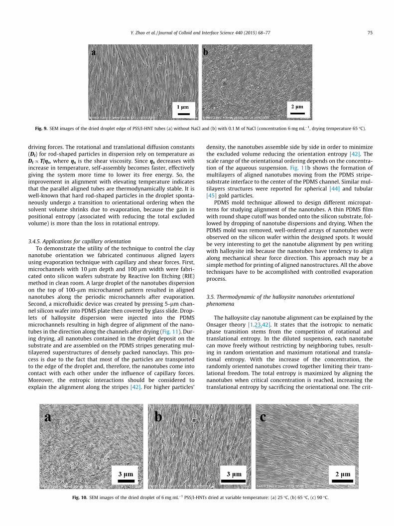
Fig. 9. SEM images of the dried droplet edge of PSS/l-HNT tubes (a) without NaCl and (b) with 0.1 M of NaCl (concentration 6 mg mL�1, drying temperature 65 �C).
Y. Zhao et al. / Journal of Colloid and Interface Science 440 (2015) 68–77 75
driving forces. The rotational and translational diffusion constants(Di) for rod-shaped particles in dispersion rely on temperature asDi / T/gs, where gs is the shear viscosity. Since gs decreases withincrease in temperature, self-assembly becomes faster, effectivelygiving the system more time to lower its free energy. So, theimprovement in alignment with elevating temperature indicatesthat the parallel aligned tubes are thermodynamically stable. It iswell-known that hard rod-shaped particles in the droplet sponta-neously undergo a transition to orientational ordering when thesolvent volume shrinks due to evaporation, because the gain inpositional entropy (associated with reducing the total excludedvolume) is more than the loss in rotational entropy.
3.4.5. Applications for capillary orientationTo demonstrate the utility of the technique to control the clay
nanotube orientation we fabricated continuous aligned layersusing evaporation technique with capillary and shear forces. First,microchannels with 10 lm depth and 100 lm width were fabri-cated onto silicon wafers substrate by Reactive Ion Etching (RIE)method in clean room. A large droplet of the nanotubes dispersionon the top of 100-lm microchannel pattern resulted in alignednanotubes along the periodic microchannels after evaporation.Second, a microfluidic device was created by pressing 5-lm chan-nel silicon wafer into PDMS plate then covered by glass slide. Drop-lets of halloysite dispersion were injected into the PDMSmicrochannels resulting in high degree of alignment of the nano-tubes in the direction along the channels after drying (Fig. 11). Dur-ing drying, all nanotubes contained in the droplet deposit on thesubstrate and are assembled on the PDMS stripes generating mul-tilayered superstructures of densely packed nanoclays. This pro-cess is due to the fact that most of the particles are transportedto the edge of the droplet and, therefore, the nanotubes come intocontact with each other under the influence of capillary forces.Moreover, the entropic interactions should be considered toexplain the alignment along the stripes [42]. For higher particles’
Fig. 10. SEM images of the dried droplet of 6 mg mL�1 PSS/l-HNT
density, the nanotubes assemble side by side in order to minimizethe excluded volume reducing the orientation entropy [42]. Thescale range of the orientational ordering depends on the concentra-tion of the aqueous suspension. Fig. 11b shows the formation ofmultilayers of aligned nanotubes moving from the PDMS stripe-substrate interface to the center of the PDMS channel. Similar mul-tilayers structures were reported for spherical [44] and tubular[45] gold particles.
PDMS mold technique allowed to design different micropat-terns for studying alignment of the nanotubes. A thin PDMS filmwith round shape cutoff was bonded onto the silicon substrate, fol-lowed by dropping of nanotube dispersions and drying. When thePDMS mold was removed, well-ordered arrays of nanotubes wereobserved on the silicon wafer within the designed spots. It wouldbe very interesting to get the nanotube alignment by pen writingwith halloysite ink because the nanotubes have tendency to alignalong mechanical shear force direction. This approach may be asimple method for printing of aligned nanostructures. All the abovetechniques have to be accomplished with controlled evaporationprocess.
3.5. Thermodynamic of the halloysite nanotubes orientationalphenomena
The halloysite clay nanotube alignment can be explained by theOnsager theory [1,23,42]. It states that the isotropic to nematicphase transition stems from the competition of rotational andtranslational entropy. In the diluted suspension, each nanotubecan move freely without restricting by neighboring tubes, result-ing in random orientation and maximum rotational and transla-tional entropy. With the increase of the concentration, therandomly oriented nanotubes crowd together limiting their trans-lational freedom. The total entropy is maximized by aligning thenanotubes when critical concentration is reached, increasing thetranslational entropy by sacrificing the orientational one. The crit-
s dried at variable temperature: (a) 25 �C, (b) 65 �C, (c) 90 �C.

Fig. 11. SEM images of PSS/l-HNTs films oriented in 5-lm channel, concentration 100 mg mL�1.
76 Y. Zhao et al. / Journal of Colloid and Interface Science 440 (2015) 68–77
ical concentration (ci�n) required for the isotropic-nematic transi-tion is expressed by the following equation [42]
ci�n ¼ 16=ðpL2DeffÞ ð1Þ
where ci�n is the critical concentration expressed as number den-sity, L is the length and Deff is the effective electrostatic diameter,which takes into account the nanorods charge. Given that the iso-tropic-nematic transition is a dynamic process, the ordering of hal-loysite is favored for longer nanotubes. Deff of charged rods is largerthan that of uncharged rods by an amount proportional to Debyescreening length. Consequently, the enhancement of the halloysitesurface charge determines an increase of Deff shifting to longerrange the average distance between the nanotubes. Accordingly,the modification of halloysite cavity with PSS, which causes a largeincrease of halloysite n-potential, leads to ordering because of thevery strong repulsive interactions between the nanotubes. Withinthis, the influence of pH and ionic strength on the nanotubes align-ment is crucial: for pH P 5, Deff is larger favoring the tubes order-ing. An increase of the ionic strength determines a decrease ofDeff (because of the screening effect), and the nanotubes alignmentis disadvantageous.
4. Conclusions
With droplet-casting method, we obtained highly ordered pat-terns of halloysite nanotubes. An evaporation of a droplet of hal-loysite isotropic dispersion on wettable substrate determines theformation of a ‘‘coffee-ring’’ deposit due to the pinning of the con-tact line, and halloysite nanotubes are aligned along the edge. Thepresence of disclinations on the deposited pattern confirms thetransition from isotropic to liquid crystal phase during solventevaporation. The concentration of the nanotube aqueous disper-sion is crucial to determine the ordering on the rim. The degreeof alignment may be controlled by changing the length and thecharge of the nanotubes as well as by the ionic strength and pHof the solvent. We demonstrated that the modification of the hal-loysite inner cavity with anionic poly(styrene sulfonate) leads tobetter ordering because of an enhancement of net negative chargeof the nanotubes. Accordingly, the self-assembly of the clay nano-tubes is favored at basic pH, while the increase of the ionic strengthcauses opposite effects by screening the tube’s surface charge. Themechanism controlling the halloysite nanotube ordering isexplained with Onsager’s theory as well. The evaporation inducedclay nanotubes orientation in microchannels was also demon-strated. Although our approach has some limitations, it was thefirst time to obtain orientation halloysite nanotubes film and itwould give a meaningful guide for explanation and application ofaligned halloysite nanotubes.
Acknowledgments
We are thankful to Dr. G. Lazzara (Palermo University, Italy) andDr. W. Wei (LaTech) for help in the experimental work and resultsdiscussion. The authors acknowledge support by NSF-1029147,NSF EPS-1003897 and FIRB 2012 (prot. RBFR12ETL5) grants. Anyopinions, findings, and conclusions or recommendations expressedin this report are those of authors and do not necessarily reflect theview of National Science Foundation. This work is performedaccording to the Russian Government Program of CompetitiveGrowth of Kazan Federal University. This work was partiallyfunded by the subsidy allocated to Kazan Federal University forthe state assignment in the sphere of scientific activities.
References
[1] Y.G. Li, Y.Y. Wu, J. Am. Chem. Soc. 131 (2009) 5851–5857.[2] B.Q. Sun, H. Sirringhaus, J. Am. Chem. Soc. 128 (2006) 16231–16237.[3] N. Byrne, D. Menzies, N. Goujon, M. Forsyth, Chem. Commun. 49 (2013) 7729–
7731.[4] Z.R. Tian, J.A. Voigt, J. Liu, B. Mckenzie, H.F. Xu, J. Am. Chem. Soc. 125 (2003)
12384–12385.[5] S.H. Lee, H.J. Lee, K. Ino, H. Shiku, T. Yao, T. Matsue, J. Phys. Chem. C 113 (2009)
19376–19381.[6] X.L. Li, L. Zhang, X.R. Wang, I. Shimoyama, X.M. Sun, W.S. Seo, H.J. Dai, J. Am.
Chem. Soc. 129 (2007) 4890–4891.[7] R.S. Mclean, X.Y. Huang, C. Khripin, A. Jagota, M. Zheng, Nano Lett. 6 (2006) 55–
60.[8] B. Li, W. Han, M. Byun, L. Zhu, Q.Z. Zou, Z.Q. Lin, ACS Nano 7 (2013) 4326–4333.[9] M. Grzelczak, J. Vermant, E.M. Furst, L.M. Liz-Marzán, ACS Nano 4 (2010)
3591–3605.[10] J. Shaver, A.N.G. Parra-Vasquez, S. Hansel, O. Portugall, C.H. Mielke, M.V.
Ortenberg, R.H. Hauge, M. Pasquali, J. Kono, ACS Nano 3 (2009) 131–138.[11] D. Klinov, K. Atlasov, A. Kotlyar, B. Dwir, E. Kapon, Nano Lett. 7 (2007) 3583–
3587.[12] H. Zhou, P. Heyer, H.J. Kim, J.H. Song, L.H. Piao, S.H. Kim, Chem. Mater. 23
(2011) 3622–3627.[13] V. Olszowka, M. Hund, V. Kuntermann, S. Scherdel, L. Tsarkova, A. Böker, ACS
Nano 3 (2009) 1091–1096.[14] S.T. Beyer, K. Walus, Langmuir 28 (2012) 8753–8759.[15] S.J. Zhang, Q.W. Li, I.A. Kinloch, A.H. Windle, Langmuir 26 (2010) 2107–2112.[16] T.A. Shastry, J.W.T. Seo, J.J. Lopez, H.N. Arnold, J.Z. Kelter, W.K. Sangwan, L.J.
Lauhon, T.J. Marks, M.C. Hersam, Small 9 (2013) 45–51.[17] W. Han, Z. Lin, Angew. Chem. Int. Ed. Engl. 51 (2012) 1534–1546.[18] Y. Liu, X.L. Zhao, B. Cai, T.F. Pei, Y.H. Tong, Q.X. Tang, Y.C. Liu, Nanoscale 6
(2014) 1323–1328.[19] R.D. Deegan, O. Bakajin, T.F. Dupont, G. Huber, S.R. Nagel, T.A. Witten, Nature
389 (1997) 827–829.[20] Q.W. Li, Y.T. Zhu, J. Phys. Chem. B 110 (2006) 13926–13930.[21] H.M. Ma, R.H. Dong, J.D.V. Horn, J.C. Hao, Chem. Commun. 47 (2011) 2047–
2049.[22] M. Byun, J. Wang, Z.Q. Lin, J. Phys.: Condens. Matter 21 (2009) 264014.[23] P.G. De Gennes, The Physics of Liquid Crystals, Oxford University Press,
London, 1974. pp. 6–374.[24] Y.M. Lvov, D.G. Shchukin, H. Mönwald, R.R. Price, ACS Nano 2 (2008) 814–820.[25] Y.M. Lvov, E. Abdullayev, Prog. Polym. Sci. 38 (2013) 1690–1719.[26] G. Cavallaro, G. Lazzara, S. Milioto, J. Phys. Chem. C 116 (2012) 21932–21938.[27] G. Cavallaro, G. Lazzara, S. Milioto, F. Parisi, V. Sanzillo, ACS Appl. Mater.
Interfaces 6 (2014) 606–612.

Y. Zhao et al. / Journal of Colloid and Interface Science 440 (2015) 68–77 77
[28] E. Abdullayev, K. Sakakibara, K. Okamoto, W.B. Wei, K. Ariga, Y.M. Lvov, ACSAppl. Mater. Interfaces 3 (2011) 4040–4046.
[29] V. Vergaro, E. Abdullayev, Y.M. Lvov, A. Zeitoun, R. Cingolani, R. Rinaldi, S.Leporatti, Biomacromolecules 11 (2010) 820–826.
[30] M.X. Liu, C.C. Wu, Y.P. Jiao, S. Xiong, C.R. Zhou, J. Mater. Chem. B 1 (2013)2078–2089.
[31] E. Abdullayev, A. Joshi, W.B. Wei, Y.F. Zhao, Y.M. Lvov, ACS Nano 6 (2012)7216–7226.
[32] W.O. Yah, A. Takahara, Y.M. Lvov, J. Am. Chem. Soc. 134 (2012) 1853–1859.[33] M. Du, B. Guo, D. Jia, Polym. Int. 59 (2010) 574–595.[34] Y.F. Zhao, E. Abdullayev, A. Vasiliev, Y.M. Lvov, J. Colloid Interface Sci. 406
(2013) 121–129.[35] R. Zhai, B. Zhang, Y.Z. Wan, C.C. Li, J.T. Wang, J.D. Liu, Chem. Eng. J. 214 (2013)
304–309.[36] L. Liu, Y.Z. Wan, Y.D. Xie, R. Zhai, B. Zhang, J.D. Liu, Chem. Eng. J. 187 (2012)
210–216.
[37] Z.Q. Luo, H.Z. Song, X.R. Feng, M.T. Run, H.H. Cui, L.C. Wu, J.G. Gao, Z.G. Wang,Langmuir 29 (2013) 12358–12366.
[38] E. Feitosa, M.R.S. Brazolin, R.M.Z.G. Naal, M.P.F.M.D. Lama, J.R. Lopes, W. Loh,M. Vasilescu, J. Colloid Interface Sci. 299 (2006) 883–889.
[39] F. Frank, Discuss. Faraday Soc. 25 (1958) 19–28.[40] S. Zhang, E. Terentjev, A. Donald, J. Phys. Chem. B 109 (2005) 13195–13199.[41] M. Mashkour, T. Kimura, F. Kimura, M. Mashkour, M. Tajvidi, Biomacromolecules
15 (2014) 60–65.[42] L. Onsager, Ann. N.Y. Acad. Sci. 51 (1949) 627–659.[43] S.J. Zhang, I.A. Kinloch, A.H. Windle, Nano Lett. 6 (2006) 568–572.[44] C.A. Fustin, G. Glasser, H.W. Spiess, U. Jonas, Langmuir 20 (2004) 9114–
9123.[45] W. Ahmed, C. Glass, E. Kooij, J. van Ruitenbeek, Nanotechnology 25 (2014)
035301.