High-throughput multiplexed fluorescence-activated droplet ...
11
HAL Id: hal-02118950 https://hal.archives-ouvertes.fr/hal-02118950 Submitted on 3 May 2019 HAL is a multi-disciplinary open access archive for the deposit and dissemination of sci- entific research documents, whether they are pub- lished or not. The documents may come from teaching and research institutions in France or abroad, or from public or private research centers. L’archive ouverte pluridisciplinaire HAL, est destinée au dépôt et à la diffusion de documents scientifiques de niveau recherche, publiés ou non, émanant des établissements d’enseignement et de recherche français ou étrangers, des laboratoires publics ou privés. High-throughput multiplexed fluorescence-activated droplet sorting Ouriel Caen, Simon Schütz, M. S. Suryateja Jammalamadaka, Jérémy Vrignon, Philippe Nizard, Tobias Schneider, Jean-Christophe Baret, Valérie Taly To cite this version: Ouriel Caen, Simon Schütz, M. S. Suryateja Jammalamadaka, Jérémy Vrignon, Philippe Nizard, et al.. High-throughput multiplexed fluorescence-activated droplet sorting. Microsystems & Nanoengi- neering, Springer Nature, 2018, 4 (1), pp.33. 10.1038/s41378-018-0033-2. hal-02118950
-
Upload
khangminh22 -
Category
Documents
-
view
4 -
download
0
Transcript of High-throughput multiplexed fluorescence-activated droplet ...

HAL Id: hal-02118950https://hal.archives-ouvertes.fr/hal-02118950
Submitted on 3 May 2019
HAL is a multi-disciplinary open accessarchive for the deposit and dissemination of sci-entific research documents, whether they are pub-lished or not. The documents may come fromteaching and research institutions in France orabroad, or from public or private research centers.
L’archive ouverte pluridisciplinaire HAL, estdestinée au dépôt et à la diffusion de documentsscientifiques de niveau recherche, publiés ou non,émanant des établissements d’enseignement et derecherche français ou étrangers, des laboratoirespublics ou privés.
High-throughput multiplexed fluorescence-activateddroplet sorting
Ouriel Caen, Simon Schütz, M. S. Suryateja Jammalamadaka, JérémyVrignon, Philippe Nizard, Tobias Schneider, Jean-Christophe Baret, Valérie
Taly
To cite this version:Ouriel Caen, Simon Schütz, M. S. Suryateja Jammalamadaka, Jérémy Vrignon, Philippe Nizard, etal.. High-throughput multiplexed fluorescence-activated droplet sorting. Microsystems & Nanoengi-neering, Springer Nature, 2018, 4 (1), pp.33. �10.1038/s41378-018-0033-2�. �hal-02118950�

Caen et al. Microsystems & Nanoengineering (2018) 4:33 Microsystems & NanoengineeringDOI 10.1038/s41378-018-0033-2 www.nature.com/micronano
ART ICLE Open Ac ce s s
High-throughput multiplexedfluorescence-activated droplet sortingOuriel Caen1, Simon Schütz2, M. S. Suryateja Jammalamadaka1, Jérémy Vrignon3, Philippe Nizard1,Tobias M. Schneider2, Jean-Christophe Baret3 and Valérie Taly1
AbstractFluorescence-activated droplet sorting (FADS) is one of the most important features provided by droplet-basedmicrofluidics. However, to date, it does not allow to compete with the high-throughput multiplexed sortingcapabilities offered by flow cytometery. Here, we demonstrate the use of a dielectrophoretic-based FADS, allowing tosort up to five different droplet populations simultaneously. Our system provides means to select droplets of differentphenotypes in a single experimental run to separate initially heterogeneous populations. Our experimental results arerationalized with the help of a numerical model of the actuation of droplets in electric fields providing guidelines forthe prediction of sorting designs for upscaled or downscaled microsystems.
IntroductionFluorescence-based cell sorting is essential in numerous
biological assays requiring high-throughput analysis andsorting of single cells. The gold standard technology forthis purpose is fluorescence-activated cell sorting(FACS)1. However, a main drawback of FACS is that itcannot support real-time analysis of single cell or inte-gration of complex assays involving single-cell manip-ulation, treatment, and final detection2. Moreover, it isnot compatible with the analysis of small cell populations(< 105 cells3). Compared with FACS, fluorescence-basedcell sorting microsystems allow to reduce sample amountsto eliminate potentially biohazardous aerosols4 and toimplement complex assays. A large variety of suchmicrodevices has been developed in recent years, based ondifferent physical mechanisms such as optical manipula-tion5, mechanical systems6, acoustophoresis7, andelectrokinetics8.
Whereas both FACS and the latter systems are efficientto screen compounds remaining within the cell or on itssurface, they are not suited for cytoplasmic or secretedproteins screening. Even though intracellular staining flowcytometry has been described, the use of protein transportinhibitors can interfere with the analysis9.An alternative solution consists in the compartmenta-
lization of cells in monodisperse emulsion droplets. Ahigh viability of encapsulated cells in such droplets hasbeen observed over several days10, and various activedroplet sorting solutions such as acoustic, magnetic,pneumatic, thermal, and electric actuation have alreadybeen described11. However, the most widespread methodis dielectrophoretic-based sorting.The former approach has indeed been democratized for
several reasons. First, dielectrophoresis is very efficient forthe sorting of water-in-oil droplets, as it is mainly gov-erned by the dielectric contrast between water and oil,independently of additives in these phases. Second, itallows the sorting of a large range of droplet volumes:from 20 fL12 to 10 nL13. Third, it allows to reach sortingrates as high as 30 kHz14, comparable with rates achievedby commercially available flow cytometers. Eventually, itis not restricted to fluorescence-based actuation, but canbe peformed through absorbance15 or morphological16,17
© The Author(s) 2018OpenAccessThis article is licensedunder aCreativeCommonsAttribution 4.0 International License,whichpermits use, sharing, adaptation, distribution and reproductionin any medium or format, as long as you give appropriate credit to the original author(s) and the source, provide a link to the Creative Commons license, and indicate if
changesweremade. The images or other third partymaterial in this article are included in the article’s Creative Commons license, unless indicated otherwise in a credit line to thematerial. Ifmaterial is not included in the article’s Creative Commons license and your intended use is not permitted by statutory regulation or exceeds the permitted use, you will need to obtainpermission directly from the copyright holder. To view a copy of this license, visit http://creativecommons.org/licenses/by/4.0/.
Correspondence: Tobias M. Schneider ([email protected]) or Jean-Christophe Baret ([email protected]) or Valérie Taly ([email protected])1INSERM UMR-S1147, CNRS SNC5014, Paris Descartes University, Equipelabellisée Ligue Nationale contre le cancer, Paris, France2Emergent Complexity in Physical Systems Laboratory (ECPS), EcolePolytechnique Fédérale de Lausanne, 1015 Lausanne, SwitzerlandFull list of author information is available at the end of the article.
1234
5678
90():,;
1234
5678
90():,;
1234567890():,;
1234
5678
90():,;

measures. As such, the application scope of biologicalassays which can be performed through dielectrophoreticsorting is very broad. In particular, dielectrophoreticfluorescence-based sorting has already demonstrated agreat interest for numerous biological applications. It hasbeen used to screen enzymes expressed intracellu-larly18,19, on the surface of cells20,21 or secreted fromcells13,22,23, as well as for the directed evolution ofenzymes20,24–26. It has also been used to screen forextracellular metabolite production or consumption27 andto screen cells for monoclonal antibody production28,29.Eventually, it allowed to perform genetic sequence-specific sorting and to recover cell genomes for down-stream nucleic acid analysis30–32.However, in all former studies, sorting could be per-
formed solely on two droplet populations, allowing toisolate a single phenotype. Indeed, despite both multi-parametric screening33–37 and multiplexed sorting38–40
have been demonstrated by FACS, mainly multi-parametric screening has been shown by dropletfluorescence-based microsystems41–45. So far only a singlestudy showed the dielectrophoretic sorting of multiple(triple) fluorescent droplet populations46. However, thiswork consisted in serially integrating binary sorters andwas limited to a throughput of 2–3 droplets per second.Here, we demonstrate the use of a single dielectrophoreticsorter, allowing to sort up to five different fluorescentdroplet populations at rates of several hundreds of dro-plets per second.
Materials and methodsMicrofluidic devices preparationThe following protocol is similar to the one we pre-
viously described in ref 47. The microfluidic devices weredesigned with conventional computer-aided design(CAD) tool (AutoCAD, AutoDesk) and printed on anoptical grade transparent film (Selba). The design of thesorting device can be found in Fig. 1 and the design of thedroplet production device can be found in Fig. S1. Moldsof SU-8 negative photoresist (MicroChem) were fabri-cated on a silicon wafer (Si-Mat) by UV exposure (MJB4contact mask aligner; SUSS MicroTec) through the pho-tolithography mask (Selba) and developed (SU-8 devel-oper; Micro-Chem). SU8-2025 was used to prepare a 35-μm deep mold for the droplet production device, andSU8-2035 was used to prepare a 50-μm deep mold for thesorting device. Curing agent was added to the poly(dimethylsiloxane) (PDMS) base (Sylgard 184 siliconeelastomer kit; DowCorning) to a final concentration of10% (w/w), mixed, and poured over the mold. Followingdegassing for 20min and cross-linking at 75 °C for 1 h, thePDMS was peeled off the mold and the input and outputports were punched with a 0.75-mm diameter biopsypunch (WPI). The holes for the sample loading wells of
the droplet production device were punched by using abiopsy puncher with a 5 mm diameter (Harris Uni-Core).Particles of PDMS were cleared from the ports usingScotch tape, rinsing with isopropanol, and drying withpressurized nitrogen. The structured side of the PDMSslab was bonded to a 75 × 50 × 1.2-mm glass microscopeslide (Corning) by exposing both parts to an oxygenplasma (PICO, Diener) and pressing them together.Finally, an additional hydrophobic surface coating wasapplied to the microfluidic channel walls by injecting thecompleted device with Aquapel glass treatment (PPGIndustries) and then purging the liquid with nitrogen gas.For the sorting chips, the PDMS device was plasmabonded to the non-conductive side of a 75 × 25 × 1.1-mmindium tin oxide glass (ITO, Delta Technologies). Theconductive side of the ITO glass was used as a counterelectrode. Electrodes were incorporated into the systemby filing the micro channels with a low-melting pointsolder (Indalloy 19, Indium corporation).
Fluid actuationDroplets were produced by flow focusing the aqueous
phase with a fluorinated oil phase (HFE7500, 3M) con-taining 2% (w/w) EA surfactant (RainDance Technolo-gies), a biocompatible PEG–PFPE amphiphilicblockcopolymer48. A red fluorescent dye, SulforhodamineB (Sigma-Aldrich), was added to the aqueous phase (PBSwater) to fluorescently label the droplets. Aqueous and oilphases were injected into the microfluidic chips using anMFCS pressure controler (Fluigent). For droplet selectionat a 80 Hz rate, droplet flow rate was ≈0.23 μL/min and oilflow rate was 8.1 μL/min. For droplet selection at a 450 Hzrate, droplet flow rate was ≈1.3 μL/min and oil flow ratewas 50 μL/min. Oil flow rates were monitored using asyringe pump controler (neMESYS, Cetoni). The dropletlibrary preparation for the fluorescence-based multiplexeddroplet sorting was performed as follows. First, five dif-ferent aqueous phases were prepared at five concentra-tions of Sulforhodamine B (9.37, 18.75, 37.5, 75, and 150μM) diluted in PBS water. These five solutions wereindependently loaded into a dedicated open well withinthe microfluidic chip. The device was embedded in apressure chamber, previously described in ref 31, such thateach well was pressurized at 500mbar. These aqueousphases were independently flow focused by oil, which waspressurized at 1 bar. The generated droplet library wasthen reinjected into the sorting device. Droplets werepressurized at 100 mbar and spaced by an oil phasepressurized at 373mbar. The central collection channelwas connected to a polytetrafluoroethylene (PTFE) tubing(Fisher Scientific) with an internal diameter (ID) of 0.56mm. Other collection channels were connected to poly-etheretherketone (PEEK) tubings (CIL Upchurch) with IDof 0.25 mm.
Caen et al. Microsystems & Nanoengineering (2018) 4:33 Page 2 of 10

Principle for multiplexed sortingTraditionally, droplet sorting is performed on two dis-
tinct droplet populations. In the absence of an externalactuation, the trajectory of the droplets in the channels isdriven by hydrodynamics. Typically, there are two outlet
channels, with one arm wider than the other. Such ageometry allows a contrast of hydrodynamic resistancebetween the two arms. Droplets thus follow the main flowtoward the less-resistant arm in the absence of an externalfield. When an external electric field is applied, the
Ground electrode 1
Ground electrode 2
Live electrode 2
Live electrode 1
Oilinjection
Dropletinjection
Sorting channel 5
Sorting channel 4
Sorting channel 1
Sorting channel 2
Sorting channel 3
Fig. 1 Design of the multiplexed droplet sorter. Top: design of the whole device. Droplets can be reinjected in the sorter and precisely spaced byoil for further sorting. Two symmetrical live and ground electrodes allow to apply an electric field above and below the central channel. Droplets canhence be deviated into one of the four channels in periphery or remain in the central channel in the absence of electric actuation. Bottom: inset ofthe sorting zone. Scale bar: 200 μm
Caen et al. Microsystems & Nanoengineering (2018) 4:33 Page 3 of 10

droplets are forced across the streamlines to flow towardthe other arm. We consider here the case of a dielectricdroplet of dielectric constant εd immersed in a perfectdielectric material of dielectric constant ε, where εd > ε.For simplicity, we use the same constant to describe thecontinuous phase fluid and the polymer in which thechannels are molded. The field oscillates at high fre-quency (30 kHz) to avoid the accumulation of free char-ges. Typically, the charge relaxation time of a waterdroplet is 0.125 ms49, therefore smaller than 30 kHz. Asno free charges are present in the system, the stress on thedroplet interface is given by the jump in Maxwell stress50,
~f ¼ ε0ε
21� ε
εd
� �E2n � 1� εd
ε
� �E2t
� �~n; ð1Þ
where ~n is the interface normal pointing outside thedroplet and En (Et) is the normal (tangential) field com-ponent in the continuous phase at the interface. Inte-grating this stress over the droplet surface gives the netdielectrophoretic force, which is independent of the signof the field and will be attractive toward regions of highfield strength. A common approximation of this force, forthe case of a spherical droplet in a weakly varying field, isgiven by the expression:
~Fdep ¼ 2πε0εK ε; εdð ÞR3∇ ~E�� ��2; ð2Þ
where K(ε, εd)= (εd− ε)/(εd+ 2ε) is theClausius–Mossotti factor, R the droplet radius, and ~E theelectric field. In the general case, the net force depends onboth the droplet shape and the electric field in the pre-sence of the droplet. With no general analytical solutionfor this problem, numerical simulations provide theproper value and distribution of the force. The dielec-trophoretic force scales with the square of the potentialdifference between the live electrode and the groundelectrode. Traditionally, a constant value of potentialdifference is chosen such that the DEP force is highenough to deviate the droplet in the relevant arm. Herewe propose to use a symmetric multidirectional sorter,and vary the potential difference or actuation timebetween the electrodes such that various amplitudes ofDEP forces can be applied. The droplet deflection can bechanged and thus allow to sort droplets toward severaldifferent channels.
Sorting designThe implementation of the sorting design is presented
in Fig. 1. In brief, an emulsion is reinjected in the centralchannel and spaced by oil. On each side of the channels, alive electrode surrounded by two ground electrodes usedfor electrical shielding is disposed in a geometrical con-figuration, allowing to maximize the dielectrophoreticforce applied at the sorting junction. The electrodes at the
sorting junctions are independently controlled by 30 kHzsinusoidal voltages amplified to a high voltage (0–1200Vpp) using a set of two amplifiers (Trek, 623B). Such afrequency is more than an order of magnitude faster thanthe time scale in our system, such that any forces due toelectrostatics would average to zero over multiple oscil-lations. At the junction, five separate outlets are designedto collect the five fractions of the droplet, depending ontheir fluorescence intensities. No voltage was applied tosort the droplets in the middle channel. Electrode acti-vation was synchronized with droplet detection throughthe Labview FPGA interface at 200 kHz. An oil injectioninlet integrated in the sorter design (see Fig. 1) allowed tohomogeneously space the droplets while they were rein-jected in the sorting device. For droplet selection at a 80Hz rate, voltage amplitude applied to the exterior chan-nels (numbers three and five) and interior channels(numbers two and four) was, respectively, 1200 and 900Vpp, with an electrode activation time of 1.7 ms. Fordroplet selection at a 450 Hz rate, voltage amplitudeapplied to the exterior channels (three, five) and interiorchannels (two, four) was 800 Vpp, with electrode activa-tion times of 3.3 and 1.17 ms, respectively. For multi-plexed fluorescence-based sorting, voltage amplitudeapplied to the exterior channels (three, five) and interiorchannels (two, four) was, respectively, 1200 and 900 Vpp,with an electrode activation time of 1 ms.
Optical detectionThe microfluidic chip was interfaced on a previously
described setup for fluorescence measurements47. In brief,the droplets continuously flow through an excitation laser(Cobolt 06-DPL 532 nm; Cobolt), and their emittedfluorescence was detected by a photomultiplier tube(PMT) (Hamamatsu H5784-20) in the range of 560–590nm. A detailed description of the used optical setup hasbeen previously reported47. A voltage proportional to theintensity of the emitted light and therefore to the dyeconcentration is then measured, recorded, and statisticallyanalyzed. The sorting decision was programmed in alabview routine to select up to five different ranges ofintensities.
Data acquisition and analysisAll videos were recorded with a high-speed digital
camera (Phantom Miro M310, Vision Research). A Houghcircled detection algorithm51 was used to roughly localizedroplets centers and sizes. This rough detection was thenrefined using Virtual Image Correlation52 based on a gray-level distribution along one cross-section of the dropletshape. This refinement allowed for a sub-pixel estimationof the 2D droplet section imaged by the high-speedcamera. Such analysis allowed to monitor droplet trajec-tories and volumes. The data acquisition and control
Caen et al. Microsystems & Nanoengineering (2018) 4:33 Page 4 of 10

procedure of optical and triggering signals is similar to theone we previously described in ref 47. The PMT signal wasrecorded and converted to 8 bits through the Analog toDigital Converter of a LabVIEW FPGA module. Thesampling frequency was adjusted to 200 kHz. At eachacquisition step, 8-bit PMT values were joined to form a64-bit word queued in a LabVIEW direct memory access(DMA) first in, first out (FIFO). DMA FIFO enables highbandwidth transfer of data from the field-programmablegate array (FPGA) to the host computer. Three 8-bitsignals were joined in these 64-bit words, such that PMTacquisition could be transferred together with the signalsof high-voltage signal triggers. On the host computer,FIFO elements were dequeued in the main LabVIEW vi.Each 64-bit word was decoded to the three original 8-bitvalues. Data were then directly streamed to the disk in aWaveform Audio FileFormat (WAV) 8-bit PCM. Anopen-source digital audio editor (Audacity) was used toconvert the signal into 16 bits format, and a home-madeMATLAB script was further used to analyze the signals.
Numerical simulationsFor the numerics, we used a 3D boundary element
method (BEM)53 on quadrilateral linear elements. Giventhe potential φ on the electrode surfaces and coupling thesolutions in the droplet and the continuous medium bymatching the potentials and normal components of thedisplacement field ~Di ¼ εi~Ei on the droplet interface, theelectrostatic Maxwell equation
Δφ ¼ 0 ð3Þ
was solved for the flux ~n � ∇φ on the electrode surfaces,and flux and potential on the droplet interface. From this,the field on the droplet surface was constructed. Theresulting Maxwell stress (1) was added to the stress due tosurface tension,
~fγ ¼ �2γκ~n ð4Þ
where γ is the surface tension and κ the mean curvature ofthe surface, to couple the inner and outer solution for aBEM-solver of the Stokes equations,
∇ �~u ¼ 0 ð5Þ∇ � σ̂ ¼~0 ð6Þ
where ~u is the flow velocity and σ̂ the Newtonian stresstensor. Coupling at the interface took into account thedifferent viscosities of the fluids. After solving for theinterface velocity, the interface was advected in an explicitEuler time step. This process was repeated until dropletshad reached the outlet of the sorter. Mesh regularity wasenforced with an active redistribution of interface verticesand a quadtree-based mesh refinement. Mesh handling andsurface integration were implemented based on the library
deal.II54, solving the linear system used Jacobi-preconditioned GMRES.The numerical code was successfully validated in a series
of tests, details can be found in ref 55. The simulationreproduced Stokes’ law for the drag force on a sphericalparticle with a relative error of order 10−7 and thedielectric drag force on a spherical droplet due to a nearbypoint charge with a relative error of order 10−2. Both thedynamic deformation of droplets due to viscous shear56
and electric fields50 was reproduced with relative errors oforder 10−2. No fitting parameters were used.
Results and discussionDroplet selectionAs a first step, we measured the efficiency of our design to
selectively drive the droplets in the different channels. In theabsence of electric field, the droplets flow to the centralchannel (Fig. 1, sorting channel 1) since the flows are laminarand the channel is designed with a reflection symmetry axis.Two decoupled live electrodes from each side of the centralchannel allow electric actuation to drive the droplets aboveand below the central channel (Fig. 1).The lower electrode is activated to sort the droplets to the
lower interior channel and the lower exterior channel (seeFig. 1, sorting channel 2 and sorting channel 3, respectively).Similarly, the upper electrode is activated to drive the dro-plets to the upper interior channel and the upper exteriorchannel (Fig. 1, sorting channel 4 and sorting channel 5,respectively). The width of the sorting channels was designedlarger than droplets diameter (75μm vs. 45 μm, respectively)to prevent friction between the droplets and channel walls.For the same reason, the depth of the sorting device waschosen to be 50 μm. As the distance between central andexterior channels is larger than the one between central andinterior channels, it is expected that higher voltages or higheractuation times are necessary to carry droplets in the exteriorchannels. Since high voltages could result in droplet elec-trosplitting, it is of interest to minimize the voltage needed todeflect droplets in exterior channels. This can be eitherachieved by increasing the electrode activation time andlowering the hydrodynamic resistance of these channels. Forthe latter purpose, we broadened the entrances of exteriorchannels, and their width was designed 10 μm larger thanother channels. These modifications did not affect thebehavior of droplets in the absence of an external field giventhe symmetry of the sorter.A 30 kHz sinusoidal voltage was generated and ampli-
fied to be applied to the electrodes connected to the chip.We calibrated the applied voltages and electrode activa-tion times to lead the droplets into the targeted sortingchannels (see Fig. 2). As expected, higher voltages oractuation times were required to direct the droplets to theexterior channels than those necessary to allow deflectioninto interior channels. We were able to reliably deflect the
Caen et al. Microsystems & Nanoengineering (2018) 4:33 Page 5 of 10

200a
b
c
d
e
f
g
h
i
j
k
l
m
n
o
100
0
–100Pos
ition
y [�
m]
–200
200
100
0
–100Pos
ition
y [�
m]
–200
200
100
0
–100Pos
ition
y [�
m]
–200
200
100
0
–100Pos
ition
y [�
m]
–200
200
100
0
–100Pos
ition
y [�
m]
–200
0
Vpp = 1200 VVpp = 1200 V (exp)
Vpp = 900 VVpp = 900 V (exp)
Vpp = 0 VVpp = 0 V (exp)
Vpp = 900 VVpp = 900 V (exp)
Vpp = 1200 VVpp = 1200 V (exp)
100 200 300 400
0 100 200 300 400
0 100 200 300 400
0 100 200 300 400
0 100 200Position x [�m]
300 400
Fig. 2 Droplet deflections into the sorting channels. a–e Droplet trajectories tracked using a home-made image analysis software (n= 600droplets for each trajectory). Simulated trajectories are shown in dashed lines. Droplets deflection rate was 80 Hz with a droplet flow rate of ≈0.23 μL/min and an oil flow rate of 8.1 μL/min. Voltage amplitude applied to the exterior channels and interior channels was, respectively, 1200 and 900 Vpp,with an electrode activation time of 1.7 ms. No voltage was applied to sort droplets in the middle channel. f–j Corresponding microscopy images ofdroplet deviation at 80 Hz (see Movies S1–5, ESI). Scale bar: 200 μm. k–o Microscopy images of droplet deviation at 450 Hz (see Movies S6–10, ESI).Droplet flow rate was ≈1.3 μL/min and oil flow rate was 50 μL/min. Voltage amplitude applied to the exterior channels and interior channels was 800Vpp, with electrode activation times of 3.3 and 1.17 ms, respectively. No voltage was applied to sort droplets in the middle channel. Scale bar: 200 μm
Caen et al. Microsystems & Nanoengineering (2018) 4:33 Page 6 of 10

droplets in the relevant sorting channels for throughputsranging from 80 to 450 Hz (see Fig. 2 and Movies S1–10in the ESI).As a next step, we compare the experimental trajec-
tories of the droplets in the external field to numericalsimulations in order to confirm the actuation mechanism.A high consistency was shown between experimental andsimulated droplet trajectories (see Fig. 2a–e). The slightmismatches observed between experimental data andsimulations can have several sources. From an experi-mental perspective, they can originate from image analysisnoise and variations in the channel thickness. As in regardto the numerics, limited spatial and temporal resolution ofthe simulation scheme could be responsible for inac-curacies. We conclude from these results that ournumerical scheme can indeed be used as an efficientpredictor of the droplet behavior in an external electricfields, providing the basis to the rational design of sortingjunctions.
Multiplexed droplet sortingIn a final step, we automated the sorting using a home-
made LabVIEW FPGA software. A library of five differentdroplet populations was generated and encoded by dif-ferent concentrations of a red fluorescent dye (Sulforho-damine B). Droplet monodispersity is a fundamentalparameter to guarantee highly quantitative assays. Assuch, in order to ensure a high monodispersity of thedroplet library, we used a previously developed multi-plexed emulsifier to generate droplets of 45 μm dia-meter31 (see Fig. S1). Such accuracy in droplet volume isessential for the robustness of sorting for several reasons.First, it ensures a high spectral resolution of the dropletlibrary allowing to properly gate each droplet population(see Fig. 3a). Second, it guarantees that droplets arehomogeneously spaced during their reinjection into thesorter such that each droplet can be triggered within thesame time delay. Finally, it allows for each droplet toconsistently be deflected with the same angle at a givenapplied voltage.Once generated the droplet library was reinjected for
sorting at a rate of 200 Hz (see Movie S11, ESI). The oilphase reservoir was pressurized at 373mbar and thedroplet phase reservoir at 100mbar. A histogram ofdroplets fluorescence levels could thus be plotted in realtime within the software interface. The software allowedfor each member of the droplet library to automatically besorted in a dedicated sorting channel based on its fluor-escence concentration. Sorting triggers were then auto-matically applied for each droplet depending on itsfluorescence concentration (see Fig. 3b). Each individualfraction is recovered and plated for imaging: the dropletsclearly exhibit distinct fluorescence levels for each sortedfraction (see Fig. 3c). The success rate of sorting actuation
was higher than 98.4%. This rate was determined as fol-lows. For each gated droplet fluorescence population, westatistically analyzed the specifications of the corre-sponding electrical trigger (electrode actuation, electrodeposition, and voltage amplitude), which was generatedduring sorting for each droplet. For more than 98.4% of62,746 analyzed events, the generated trigger was con-sistent with the expected one. Actuation errors were dueto instabilities during droplets reinjection which resultedin irregular spacing between the droplets at the sortingjunction. Such irregular spacing is due to coalesced dro-plets. Droplet coalescence was minimized by the use ofsurfactants in the oil phase, filtering of reagants, andgentle experimental handling.
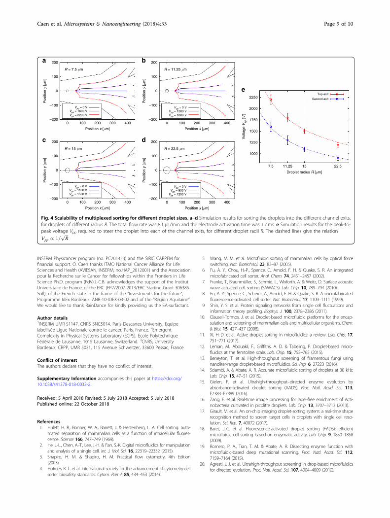
Scaling relationshipsThe combination of our experiments and a reliable
numerical method to solve the flow of droplets in externalfields is finally used to discuss the scaling properties of oursorting junction. We also demonstrated numerically thatour sorting design could be used to sort a wide range ofdroplet volumes (spreading over an order of magnitude)by properly calibrating applied voltages (see Fig. 4). Forthe range of droplet radii studied, the voltage Vpprequired to steer droplets of radius R into the exits scaleswith Vpp / 1=
ffiffiffiR
p. Due to the influence of the top and
bottom walls, the drag force is approximately proportionalto57
FDrag / R2UDrift ð7Þ
for R in the range we consider. Since the dielectrophoreticforce (2) scales with
FDEP / R3V 2pp; ð8Þ
the drift velocity UDrift has the scaling
UDrift / RV 2pp ð9Þ
and is therefore constant if Vpp / 1=ffiffiffiR
p.
ConclusionsIn summary, we have designed a new type of micro-
fluidic sorter for multiplex sorting of droplet libraries.Our strategy is based on the most widely adopted tech-nology for fluorescence-based droplet sorting, which isdielectrophoretic actuation. We show that up to fivefractions can be isolated in one single run at a high-throughput, up to 200 droplets per second. We thereforeovercome here the limitation of traditionally bidirectionalsorter which restrict their use to the separation of twodroplet populations. Such a sorting system could bevaluable to sort cells with different phenotypes in a singleround, through either fluorescence-, absorbance-, ormorphological-based actuation. The comparison of our
Caen et al. Microsystems & Nanoengineering (2018) 4:33 Page 7 of 10

experiments and numerical simulations validate the phy-sical ground of the droplet actuation model. We can nowpredict with numerical simulations the properties of thesorter for different droplet sizes. We believe that thisnumerical approach will be useful in the long run torationally design devices and go beyond the trial-and-error methods used until now.
AcknowledgementsThis work was supported by the Ministère de l’Enseignement Supérieur et de laRecherche, the Université Paris-Descartes, the Centre National de la RechercheScientifique (CNRS) and the Institut National de la Santé et de la RechercheMédicale (INSERM). V. Taly acknowledges the financial support of AgenceNationale de la Recherche (ANR Chipset, no. ANR-15-CE11-0008-04), ITMOCancer AVIESAN (Alliance Nationale pour les Sciences de la Vie et de la Santé,National Alliance for Life Sciences and Health) within the framework of theCancer Plan, the ligue nationale contre le cancer (LNCC, Program “Equipelabelisée LIGUE” no. EL2016.LNCC/VaT) and HTE Program-HetColi network,
104a
b
c
103
102
101
Dro
plet
cou
nt
100
–0.8
6
5
4
3
Dro
plet
fluo
resc
ence
(V
)
2
1
00 30 60
Time (ms)
90
Upper electrode
Lower electrode
0.8
0.6
0.4
0.2
0
–0.2
Ele
ctro
de v
olta
ge (
kV)
–0.4
–0.6
–0.8
–0.6 –0.4 –0.2 0
Droplet fluorescence (log(V))
0.2 0.4 0.6 0.8
Upper electrodeactivation
0.9 kVpp 1.2 kVpp
lower electrodeactivation
1
Fig. 3 Automated fluorescence-based droplet sorting. a Fluorescence histogram of the droplet library, n= 86,430 droplets. Sorting gatesselecting the different fluorescent droplet populations for electric actuation are highlighted as red rectangles. b Time series showing sorting triggersfor different members of the droplet library. Sorting actuation efficiency was higher than 98.4%, n= 62,746 droplets. c Fluorescence microscopyimages of sorted droplets. Left to right: droplet populations 1–5 are respectively represented with corresponding fluorescence intensities (mean ± s.d.[a.u]): 4.1 ± 0.01, 10.6 ± 0.01, 31.2 ± 1.1, 46.5 ± 0.7, and 112.3 ± 1.7. Scale bar: 200 μm (droplets volume is 48 pL in all images, variability is due to theimaging conditions)
Caen et al. Microsystems & Nanoengineering (2018) 4:33 Page 8 of 10
INSERM Physicancer program (no. PC201423) and the SIRIC CARPEM forfinancial support. O. Caen thanks ITMO National Cancer Alliance for LifeSciences and Health (AVIESAN, INSERM, no.HAP_2012001) and the Associationpour la Recherche sur le Cancer for fellowships within the Frontiers in LifeScience Ph.D. program (FdV).J.-C.B. acknowledges the support of the InstitutUniversitaire de France, of the ERC (FP7/2007-2013/ERC Starting Grant 306385-SofI), of the French state in the frame of the “Investments for the future”,Programme IdEx Bordeaux, ANR-10-IDEX-03-02 and of the “Region Aquitaine”.We would like to thank RainDance for kindly providing us the EA-surfactant.
Author details1INSERM UMR-S1147, CNRS SNC5014, Paris Descartes University, Equipelabellisée Ligue Nationale contre le cancer, Paris, France. 2EmergentComplexity in Physical Systems Laboratory (ECPS), Ecole PolytechniqueFédérale de Lausanne, 1015 Lausanne, Switzerland. 3CNRS, UniversityBordeaux, CRPP, UMR 5031, 115 Avenue Schweitzer, 33600 Pessac, France
Conflict of interestThe authors declare that they have no conflict of interest.
Supplementary Information accompanies this paper at https://doi.org/10.1038/s41378-018-0033-2.
Received: 5 April 2018 Revised: 5 July 2018 Accepted: 5 July 2018Published online: 22 October 2018
References1. Hulett, H. R., Bonner, W. A., Barrett, J. & Herzenberg, L. A. Cell sorting: auto-
mated separation of mammalian cells as a function of intracellular fluores-cence. Science 166, 747–749 (1969).
2. He, J.-L., Chen, A.-T., Lee, J.-H. & Fan, S.-K. Digital microfluidics for manipulationand analysis of a single cell. Int. J. Mol. Sci. 16, 22319–22332 (2015).
3. Shapiro, H. M. & Shapiro, H. M. Practical flow cytometry, 4th Edition(2003).
4. Holmes, K. L. et al. International society for the advancement of cytometry cellsorter biosafety standards. Cytom. Part A 85, 434–453 (2014).
5. Wang, M. M. et al. Microfluidic sorting of mammalian cells by optical forceswitching. Nat. Biotechnol. 23, 83–87 (2005).
6. Fu, A. Y., Chou, H.-P., Spence, C., Arnold, F. H. & Quake, S. R. An integratedmicrofabricated cell sorter. Anal. Chem. 74, 2451–2457 (2002).
7. Franke, T., Braunmüller, S., Schmid, L., Wixforth, A. & Weitz, D. Surface acousticwave actuated cell sorting (SAWACS). Lab. Chip. 10, 789–794 (2010).
8. Fu, A. Y., Spence, C., Scherer, A., Arnold, F. H. & Quake, S. R. A microfabricatedfluorescence-activated cell sorter. Nat. Biotechnol. 17, 1109–1111 (1999).
9. Shin, Y. S. et al. Protein signaling networks from single cell fluctuations andinformation theory profiling. Biophys. J. 100, 2378–2386 (2011).
10. Clausell-Tormos, J. et al. Droplet-based microfluidic platforms for the encap-sulation and screening of mammalian cells and multicellular organisms. Chem.& Biol. 15, 427–437 (2008).
11. Xi, H.-D. et al. Active droplet sorting in microfluidics: a review. Lab. Chip. 17,751–771 (2017).
12. Leman, M., Abouakil, F., Griffiths, A. D. & Tabeling, P. Droplet-based micro-fluidics at the femtolitre scale. Lab. Chip. 15, 753–765 (2015).
13. Beneyton, T. et al. High-throughput screening of filamentous fungi usingnanoliter-range droplet-based microfluidics. Sci. Rep. 6, 27223 (2016).
14. Sciambi, A. & Abate, A. R. Accurate microfluidic sorting of droplets at 30 kHz.Lab. Chip. 15, 47–51 (2015).
15. Gielen, F. et al. Ultrahigh-throughput–directed enzyme evolution byabsorbance-activated droplet sorting (AADS). Proc. Natl. Acad. Sci. 113,E7383–E7389 (2016).
16. Zang, E. et al. Real-time image processing for label-free enrichment of Acti-nobacteria cultivated in picolitre droplets. Lab. Chip. 13, 3707–3713 (2013).
17. Girault, M. et al. An on-chip imaging droplet-sorting system: a real-time shaperecognition method to screen target cells in droplets with single cell reso-lution. Sci. Rep. 7, 40072 (2017).
18. Baret, J.-C. et al. Fluorescence-activated droplet sorting (FADS): efficientmicrofluidic cell sorting based on enzymatic activity. Lab. Chip. 9, 1850–1858(2009).
19. Romero, P. A., Tran, T. M. & Abate, A. R. Dissecting enzyme function withmicrofluidic-based deep mutational scanning. Proc. Natl. Acad. Sci. 112,7159–7164 (2015).
20. Agresti, J. J. et al. Ultrahigh-throughput screening in drop-based microfluidicsfor directed evolution. Proc. Natl. Acad. Sci. 107, 4004–4009 (2010).
200a b
c d
e
100
0
–100
Pos
ition
y [�
m]
–200
200
100
0
–100
Pos
ition
y [�
m]
–200
200
2250Top exit
Second exit
2000
1750
1500
Vol
tage
Vpp
[V]
1250
1000
7.5 11.25 15 22.5
100
0
–100
Pos
ition
y [�
m]
–200
200
100
0
–100
Pos
ition
y [�
m]
–200
0 100
R = 7.5 �m
R = 15 �m
R = 11.25 �m
R = 22.5 �m
Vpp = 0 VVpp = 1600 VVpp = 2200 V
Vpp = 0 VVpp = 1100 VVpp = 1500 V
Vpp = 0 VVpp = 1300 VVpp = 1800 V
Vpp = 0 VVpp = 900 V
Vpp = 1200 V
200
Position x [�m]
300 400
0 100 200
Position x [�m]
300 400
0 100 200
Position x [�m]
300 400
0 100 200
Position x [�m]
Droplet radius R [�m]
300 400
Fig. 4 Scalability of multiplexed sorting for different droplet sizes. a–d Simulation results for sorting the droplets into the different channel exits,for droplets of different radius R. The total flow rate was 8.1 μL/min and the electrode activation time was 1.7 ms. e Simulation results for the peak-to-peak voltage Vpp required to steer the droplet into each of the channel exits, for different droplet radii R. The dashed lines give the relation
Vpp / 1=ffiffiffiR
p
Caen et al. Microsystems & Nanoengineering (2018) 4:33 Page 9 of 10

21. Granieri, L., Baret, J.-C., Griffiths, A. D. & Merten, C. A. High-throughputscreening of enzymes by retroviral display using droplet-based microfluidics.Chem. & Biol. 17, 229–235 (2010).
22. Sjostrom, S. L. et al. High-throughput screening for industrial enzyme pro-duction hosts by droplet microfluidics. Lab. Chip. 14, 806–813 (2014).
23. Najah, M. et al. Droplet-based microfluidics platform for ultra-high-throughputbioprospecting of cellulolytic microorganisms. Chem. & Biol. 21, 1722–1732(2014).
24. Kintses, B. et al. Picoliter cell lysate assays in microfluidic droplet compartmentsfor directed enzyme evolution. Chem. & Biol. 19, 1001–1009 (2012).
25. Fallah-Araghi, A., Baret, J.-C., Ryckelynck, M. & Griffiths, A. D. A completelyin vitro ultrahigh-throughput droplet-based microfluidic screening system forprotein engineering and directed evolution. Lab. Chip. 12, 882–891 (2012).
26. Beneyton, T., Coldren, F., Baret, J.-C., Griffiths, A. D. & Taly, V. CotA laccase: high-throughput manipulation and analysis of recombinant enzyme librariesexpressed in E. coli using droplet-based microfluidics. Analyst 139, 3314–3323(2014).
27. Wang, B. L. et al. Microfluidic high-throughput culturing of single cells forselection based on extracellular metabolite production or consumption. Nat.Biotechnol. 32, 473 (2014).
28. El Debs, B., Utharala, R., Balyasnikova, I. V., Griffiths, A. D. & Merten, C. A.Functional single-cell hybridoma screening using droplet-based microfluidics.Proc. Natl. Acad. Sci. 109, 11570–11575 (2012).
29. Mazutis, L. et al. Single-cell analysis and sorting using droplet-based micro-fluidics. Nat. Protoc. 8, 870–891 (2013).
30. Eastburn, D. J., Sciambi, A. & Abate, A. R. Identification and genetic analysis ofcancer cells with PCR-activated cell sorting Nucleic Acids Res. 42, e128(2014).
31. Lim, J. et al. Parallelized ultra-high throughput microfluidic emulsifier formultiplex kinetic assays. Biomicrofluidics 9, 034101 (2015).
32. Eastburn, D. J. et al. Microfluidic droplet enrichment for targeted sequencing.Nucleic Acids Res. 43, e86–e86 (2015).
33. Li, Y., Cu, Y. T. H. & Luo, D. Multiplexed detection of pathogen DNA with DNA-based fluorescence nanobarcodes. Nat. Biotechnol. 23, 885–889 (2005).
34. Krutzik, P. O. & Nolan, G. P. Fluorescent cell barcoding in flow cytometry allowshigh-throughput drug screening and signaling profiling. Nat. Methods 3,361–368 (2006).
35. Irish, J. M. et al. Single cell profiling of potentiated phospho-protein networksin cancer cells. Cell 118, 217–228 (2004).
36. Perez, O. D. & Nolan, G. P. Simultaneous measurement of multiple activekinase states using polychromatic flow cytometry. Nat. Biotechnol. 20, 155–162(2002).
37. Sachs, K., Perez, O., Pe’er, D., Lauffenburger, D. A. & Nolan, G. P. Causal protein-signaling networks derived from multiparameter single-cell data. Science 308,523–529 (2005).
38. Hunter, M. P. et al. Detection of microRNA expression in human peripheralblood microvesicles. PLoS. One. 3, e3694 (2008).
39. Gosselin, D. et al. Environment drives selection and function of enhancerscontrolling tissue-specific macrophage identities. Cell 159, 1327–1340(2014).
40. Kierdorf, K. et al. Microglia emerge from erythromyeloid precursors via Pu. 1-and Irf8-dependent pathways. Nat. Neurosci. 16, 273–280 (2013).
41. Baret, J.-C., Beck, Y., Billas-Massobrio, I., Moras, D. & Griffiths, A. D. Quantitativecell-based reporter gene assays using droplet-based microfluidics. Chem. &Biol. 17, 528–536 (2010).
42. Brouzes, E. et al. Droplet microfluidic technology for single-cell high-throughput screening. Proc. Natl. Acad. Sci. 106, 14195–14200 (2009).
43. Kang, D.-K. et al. 3D droplet microfluidic systems for high-throughput biolo-gical experimentation. Anal. Chem. 87, 10770–10778 (2015).
44. Boedicker, J. Q., Li, L., Kline, T. R. & Ismagilov, R. F. Detecting bacteria anddetermining their susceptibility to antibiotics by stochastic confinement innanoliter droplets using plug-based microfluidics. Lab. Chip. 8, 1265–1272(2008).
45. Price, A. K., MacConnell, A. B. & Paegel, B. M. h v SABR: photochemicaldose–response bead screening in droplets. Anal. Chem. 88, 2904–2911(2016).
46. Frenzel, D. & Merten, C. A. Microfluidic train station: highly robust and multi-plexable sorting of droplets on electric rails. Lab. Chip. 17, 1024–1030(2017).
47. Lu, H. et al. High throughput single cell counting in droplet-based micro-fluidics. Sci. Rep. 7, 1366 (2017).
48. Holtze, C. et al. Biocompatible surfactants for water-in-fluorocarbon emulsions.Lab. Chip. 8, 1632–1639 (2008).
49. Zhou, H. & Yao, S. Electrostatic charging and control of droplets in microfluidicdevices. Lab. Chip. 13, 962–969 (2013).
50. Sherwood, J. D. Breakup of fluid droplets in electric and magnetic fields. J.Fluid. Mech. 188, 133 (1988).
51. D’Orazio, T., Guaragnella, C., Leo, M. & Distante, A. A new algorithm for ballrecognition using circle Hough transform and neural classifier. PatternRecognit. 37, 393–408 (2004).
52. Sutton, M. A., Orteu, J. J. & Schreier, H. Image correlation for shape, motion anddeformation measurements: basic concepts, theory and applications (SpringerScience & Business Media, Springer US 2009).
53. Pozrikidis, C. Boundary Integral and Singularity Methods in Linearized ViscousFlow (Cambridge University Press, Cambridge 1992).
54. Bangerth, W. et al. The deal.II Library, Version 8.4 Journal of NumericalMathematics 24, 135–141 (2016).
55. Schütz, S. S. PhD Thesis, École Polytechnique Fédérale de Lausanne (2018).56. Stone, H. A. & Leal, L. G. Relaxation and Breakup of an Initially Extended Drop
in an Otherwise Quiescent Fluid. J. Fluid. Mech. 198, 399–427 (1989).57. Keh, H. J. & Chen, P. Y. Slow motion of a droplet between two parallel plane
walls. Chem. Eng. Sci. 56, 6863–6871 (2001).
Caen et al. Microsystems & Nanoengineering (2018) 4:33 Page 10 of 10