Numerical Investigation of Droplet-Droplet Coalescence and Droplet-Interface Coalescence
8
1 Copyright © 2014 by ASME NUMERICAL INVESTIGATION OF DROPLET- DROPLET COALESCENCE AND DROPLET-INTERFACE COALESCENCE A. Mansouri, H. Arabnejad, R. S. Mohan The University of Tulsa 800 S Tucker Drive, Tulsa, OK -74104 E-mail: [email protected] ABSTRACT The oil produced from offshore reservoirs normally contains considerable amount of water. The separation of water from oil is very crucial in petroleum industry. Studying the coalescence of two droplets or one droplet and interface can lead to better understanding of oil-water separation process. In this study, the coalescence of two droplets and droplet-interface are simulated using a commercial Computational Fluid Dynamics (CFD) code FLUENT 14. In order to track the interface of two fluids, two approaches, Volume of Fluid (VOF) and Level-Set method were utilized. The results are compared with experimental measurements in literature and good agreement was observed. The effect of different parameters such as droplet velocities, interfacial tension, viscosity of the continuous phase and off-center collision on the coalescence time has been investigated. The results revealed that coalescence time decreases as the droplet velocities increase. Also, continuous phase with higher viscosities and lower water- oil interfacial tension, increase the coalescence time. NOMENCLATURE B impact number (X/2R) n surface normal vector We Weber number (We=2Rρu rel 2 /σ) R droplet radius, μm X off-center distance of two droplet centers in the direction normal to velocity, μm p pressure, Pa u velocity, m/s t time, ms σ surface tension, N/m α volume-fraction function Φ Level Set function ρ density, kg/m 3 μ viscosity, cP κ local curvature of the interface Subscripts rel relative o oil phase w water phase SF surface force INTRODUCTION Binary droplet collision phenomenon has been investigated experimentally and numerically by many researchers, since it is important in many engineering applications including spray cooling [1], internal combustion engines [2] and coating [3]. Another important application of this phenomenon is in the oil industry, where dispersed water droplets in the crude oil collide and coalesce and eventually water is separated from oil. In offshore reservoirs producing crude oil containing a considerable amount of water is inevitable, therefore separation of water from crude oil is very crucial in oil treatment. Collisional behavior of droplets has been studied experimentally by Qian and Law (1997) [4] and various flow regimes were proposed in terms of Weber number and impact parameter, where the Weber number (We=2Rρu rel 2 /σ) and impact number (B=X/(2R)). According to this study collisional behavior of droplets could be classified into 5 regimes: (I) coalescence after minor deformation, (II) bouncing, (III) coalescence after substantial deformation, (IV) coalescence followed by separation for near head-on collisions, and (V) coalescence followed by separation for off-center collisions. Proceedings of the ASME 2014 4th Joint US-European Fluids Engineering Division Summer Meeting FEDSM2014 August 3-7, 2014, Chicago, Illinois, USA FEDSM2014-21642
Transcript of Numerical Investigation of Droplet-Droplet Coalescence and Droplet-Interface Coalescence

1 Copyright © 2014 by ASME
NUMERICAL INVESTIGATION OF DROPLET- DROPLET COALESCENCE AND DROPLET-INTERFACE COALESCENCE
A. Mansouri, H. Arabnejad, R. S. Mohan The University of Tulsa
800 S Tucker Drive, Tulsa, OK -74104 E-mail: [email protected]
ABSTRACT The oil produced from offshore reservoirs normally
contains considerable amount of water. The separation of water
from oil is very crucial in petroleum industry. Studying the
coalescence of two droplets or one droplet and interface can
lead to better understanding of oil-water separation process. In
this study, the coalescence of two droplets and droplet-interface
are simulated using a commercial Computational Fluid
Dynamics (CFD) code FLUENT 14. In order to track the
interface of two fluids, two approaches, Volume of Fluid (VOF)
and Level-Set method were utilized. The results are compared
with experimental measurements in literature and good
agreement was observed. The effect of different parameters
such as droplet velocities, interfacial tension, viscosity of the
continuous phase and off-center collision on the coalescence
time has been investigated. The results revealed that
coalescence time decreases as the droplet velocities increase.
Also, continuous phase with higher viscosities and lower water-
oil interfacial tension, increase the coalescence time.
NOMENCLATURE B impact number (X/2R)
n surface normal vector
We Weber number (We=2Rρurel 2/σ)
R droplet radius, μm
X off-center distance of two droplet centers in the
direction normal to velocity, μm
p pressure, Pa
u velocity, m/s
t time, ms
σ surface tension, N/m
α volume-fraction function
Φ Level Set function
ρ density, kg/m3
μ viscosity, cP
κ local curvature of the interface
Subscripts
rel relative
o oil phase
w water phase
SF surface force
INTRODUCTION Binary droplet collision phenomenon has been investigated
experimentally and numerically by many researchers, since it is
important in many engineering applications including spray
cooling [1], internal combustion engines [2] and coating [3].
Another important application of this phenomenon is in the oil
industry, where dispersed water droplets in the crude oil collide
and coalesce and eventually water is separated from oil. In
offshore reservoirs producing crude oil containing a
considerable amount of water is inevitable, therefore separation
of water from crude oil is very crucial in oil treatment.
Collisional behavior of droplets has been studied
experimentally by Qian and Law (1997) [4] and various flow
regimes were proposed in terms of Weber number and impact
parameter, where the Weber number (We=2Rρurel2/σ) and
impact number (B=X/(2R)). According to this study collisional
behavior of droplets could be classified into 5 regimes: (I)
coalescence after minor deformation, (II) bouncing, (III)
coalescence after substantial deformation, (IV) coalescence
followed by separation for near head-on collisions, and (V)
coalescence followed by separation for off-center collisions.
Proceedings of the ASME 2014 4th Joint US-European Fluids Engineering Division Summer Meeting FEDSM2014
August 3-7, 2014, Chicago, Illinois, USA
FEDSM2014-21642

2 Copyright © 2014 by ASME
Numerous studies are devoted to numerical simulations of
coalescence behavior of binary droplet collisions using different
modeling techniques for tracking the interfaces. These
techniques are either front tracking methods (such as marker-
and-cell, boundary integral method) or front capturing methods
(such as Level set, Volume of Fluid (VOF) and lattice
Boltzmann). Front tracking methods are based on Lagrangian
approach and track the marker particles to identify the
interfaces. According to literature [5], front tracking methods
fail when interfaces are very irregular and complex and for
these type of problems, front capturing methods are more
suitable. In this study, the coalescence of two water droplets in
the crude oil as a continuous phase is investigated. Moreover,
droplet-interface coalescence is investigated which is important
for designing and optimization of the oil-water separators.
NUMERICAL METHOD In this study, the droplet-droplet and droplet-interface
coalescence are investigated using a commercial CFD code
Fluent 14. In these simulations, droplets are placed at a certain
distance from each other with certain initial velocity and then
interfaces are tracked by Volume of Fluid (VOF) approach. In
this method the averaged-volume-fraction function, α is
transported by the flow [6]:
0.
u
t
(1)
Where:
regionInterface
phasecontinuoustheIn
dropletstheIn
,10
,0
,1
(2)
The velocity field is then determined solving mass and
momentum equations for two immiscible fluids in the whole
domain:
0).(
u
t
(3)
SFFupuut
u
2).( (4)
ρ, μ are the density and viscosity, respectively and for water
droplets in oil are defined by:
ow )1( (5)
ow )1( (6)
FSF is the surface tension force which only applies for
interface cells. This force appears as the source term in the
momentum equation as:
nFSF ...2 (7)
κ and n are the surface local curvature and surface normal
vector, respectively.
VALIDATION OF SIMULATIONS Since most of the experimental data mentioned in the
literature are for the case of liquid droplet coalescence in gas,
the simulation for liquid-liquid binary droplet collision is
validated by the numerical results of Mohammadi et al. (2012)
[7]. In this case the water droplet on the right side is stagnant
and the other droplet is moving toward it and then two droplets
collide and merge. As shown in Fig. 1 good agreement between
the two set of results is observed. The parameter values for the
simulations are shown in Table 1.
Time
(ms) Reference[7] Present work
0
0.3
0.4
0.5
0.6
0.7
0.8
0.9
1
1.1
1.2
1.5
Figure 1. Comparison of the Collision Sequence Mentioned in
Reference [7] and Present work

3 Copyright © 2014 by ASME
Table 1. Simulation Parameters Corresponding to the Results
Presented in Fig. 1.
parameter value
R (μm) 100 urel (m/s) 1.5 σ (N/m) 0.028 ρw (kg/m3) 1000 ρo (kg/m3) 875 μw (cP) 1 μo (cP) 2
The evolution of the coalescence of a liquid droplet with the
identical liquid interface is presented in Fig. 2 and the
simulation results are compared with the experimental images
by Blanchette and Bigioni (2006) [8]. The experimental data
are for one ethanol droplet which is released on top of the
interface between ethanol and air and was simulated using the
parameters in Table 2. Good agreement between the
experimental images and simulation results is shown in Fig. 2,
however some discrepancies occur after t=2.62 ms and at
t=3.57 ms instead of formation of a tear shaped drop, in the
simulation snapshot droplet totally coalesces with the interface.
As mentioned in [8] when the drops are gently placed on the
interface of the identical liquid with air, the air film between the
droplet and interface is drained. Then the capillary waves move
upward on the droplet surface until a cylindrical column is
formed. Due to the surface tension the column narrows from the
place it contacts the liquid interface, and under appropriate
conditions a daughter droplet will form with approximately half
the size of the initial drop. In this process, the surface tension
determines whether the column drop narrows from its neck and
forms the daughter drop or it completely coalesces with the
liquid interface. From the numerical simulation perspectives,
any small error in computing the drop surface curvature and
consequently the surface tension can significantly affect the
process of formation of the daughter drop in numerical results.
Although Blanchete et al. [8] with modifying the air viscosity
and density have observed the formation of the second drop in
their numerical simulation, current study with the exact air and
ethanol physical parameters used in the experiments did not
show that. Utilizing higher order interface tracking methods
could resolve this discrepancy, which have some effects on the
results when the surface tension becomes important.
Table 2. Simulation Parameters Corresponding to the Results
Presented in Fig. 2
parameter value
R (μm) 535 σ (N/m) 0.022 ρethanol (kg/m3) 786 ρair (kg/m3) 1.225 μethanol (cP) 1.05 μair (cP) 0.0178
The influence of interface tracking technique on the
simulation results is also investigated using Level Set method
which is a powerful numerical technique for computing the
interface motions. In this method, a smooth scalar function Φ is
defined in the way that it is zero at the interface, positive in one
phase and negative in other phase [9].
regionInterface
phasecontinuoustheIn
dropletstheIn
,0
,1
,1
(8)
Time
ms Reference[8] Present work
0
0.53
1.15
1.40
2.62
3.57
Figure 2. Comparison Between the Simulation Results with the
Experimental Data of Blanchette and Bigioni (2006)

4 Copyright © 2014 by ASME
Similar to VOF method, in the Level Set method the
interface is also adverted by external velocity field:
0.
u
t
(9)
Both Level Set and VOF methods have advantages and
disadvantages. The standard VOF method conserves the mass,
but it is very difficult to achieve higher order accuracy for this
method, while the Level Set method does not conserve the mass
and obtaining higher order accuracies is easy. Coupled Level
Set – VOF (CLSVOF) method combines the advantages of both
methods. Fig. 3 compares the collision sequence of two water
droplets computed with both VOF and CLSVOF methods. Two
approaches are shown to give similar results, indicating that in
this problem, standard VOF method can achieve good results.
Time
ms (a) VOF (b) CLSVOF
0
0.1
0.2
0.3
0.4
0.5
0.9
1.4
1.7
Figure 3. Collision Sequence Obtained by Two Interface Tracking
Approaches a) VOF, b) CLSVOF
RESULTS AND DISCUSSION In this section, the influence of different parameters on
droplet-droplet coalescence phenomenon is investigated. In
these simulations two water droplets are moving toward each
other in oil as a continuous phase. Each droplet is moving with
velocity, u and hence the urel=2u. Table 1 shows the physical
parameters used in the simulations for oil and water. One of the
most important factors, affecting the coalescence is the viscosity
of the continuous phase. Because merging or bouncing of the
two droplets is the consequence of the rupture of the film
between two droplets. If droplets have sufficient energy to
squeeze out the film of the continuous phase between them,
then the two droplets will merge together. Increasing the
viscosity of the continuous phase hinders the film rupture and
consequently increases the coalescence time. It is assumed that
the coalescence time is the time taken until two drops drain out
the film of the continuous phase between them and bond
together. The collision sequence is illustrated in Fig. 4 for μ=2,
4 and 8 cP. As shown in the figure, for μ=2 cP case, two
droplets make contact and rupture the film after 0.4 ms while
this happens after 0.5 ms in the case of μ=8 cP.
As mentioned earlier, different impact numbers (B) and We
numbers can lead to various collision regimes. In Fig. 5, the
influence of off-center collision or in other words, B parameter,
on coalescence time is shown. In the case of head-on collision,
two droplets rupture the film after 0.3 ms, while in off-center
case it delays until 0.4 ms after the initial time. Because in the
case of off-center collision, only normal component of the
velocity is responsible for film rupturing and tangential
component only rotates the merged droplet. As shown in the
results of simulation for B=0.6, for t=0.5, 0.9, 1.4 and 1.7 ms,
apparently the merged mass is rotating due to the tangential
velocity component. Another factor which is important in
coalescence phenomenon is the surface tension σ. This
parameter is responsible for the shape deformation of the
droplets during the coalescence process. Based on the snapshots
shown in Fig. 6, increasing the surface tension reduces the
coalescence time. The results also imply that surfactants such as
asphaltene decrease the interfacial tension between the oil and
water, and consequently increase the coalescence time.
One of the most important factors in coalescence process is
the collision velocity. Collision velocity or the kinetic energy of
the two droplets is essential in the process of rupturing the film
between the droplets and thus determines whether the two
droplets merge or bounce. In Fig. 7, simulations for urel=1.5 and
3 m/s are performed. Because the approaching velocities for
two cases are different, two water droplets touch each other at
t=0.21 ms in case of urel= 3 m/s while it happens at t=0.29 ms
for the case of urel= 1.5 m/s. After two drops touch each other,
the time taken for them to coalescence is 0.03 and 0.05 ms for
the case of urel= 3 m/s and urel=1.5 m/s, respectively. Therefore
increasing the approaching velocity slightly decreases the
coalescence time. Although there is some amount of oil
entrapped in the merged water droplet for all the cases, In the
case of urel=3 m/s, the amount of oil which is entrapped inside
the merged water droplet is more than the other case. During the
process of the oil film drainage, because of high collisional
velocity in this case, sufficient time for film rupture may not be
available and small amount of oil is trapped inside the merged
water droplet. Fig. 8 compares the coalescence of two water
droplets in oil versus the two oil droplets in the water. The
5 Copyright © 2014 by ASME
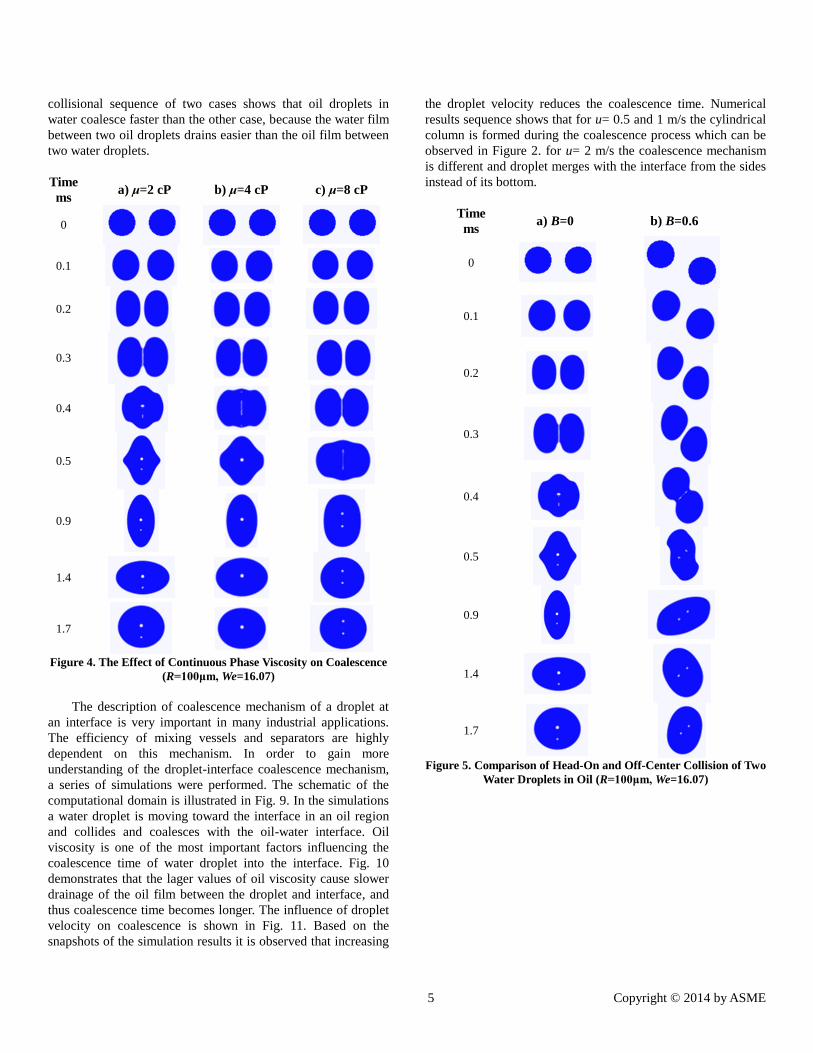
collisional sequence of two cases shows that oil droplets in
water coalesce faster than the other case, because the water film
between two oil droplets drains easier than the oil film between
two water droplets.
Time
ms a) μ=2 cP b) μ=4 cP c) μ=8 cP
0
0.1
0.2
0.3
0.4
0.5
0.9
1.4
1.7
Figure 4. The Effect of Continuous Phase Viscosity on Coalescence
(R=100μm, We=16.07)
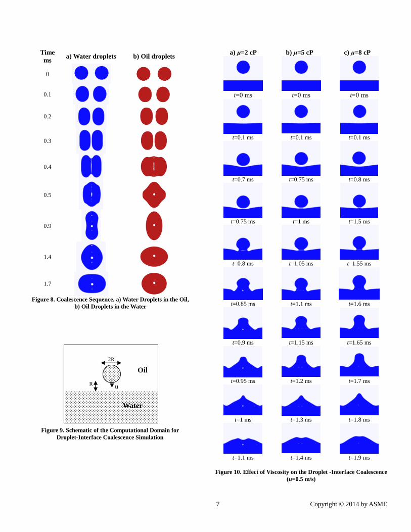
The description of coalescence mechanism of a droplet at
an interface is very important in many industrial applications.
The efficiency of mixing vessels and separators are highly
dependent on this mechanism. In order to gain more
understanding of the droplet-interface coalescence mechanism,
a series of simulations were performed. The schematic of the
computational domain is illustrated in Fig. 9. In the simulations
a water droplet is moving toward the interface in an oil region
and collides and coalesces with the oil-water interface. Oil
viscosity is one of the most important factors influencing the
coalescence time of water droplet into the interface. Fig. 10
demonstrates that the lager values of oil viscosity cause slower
drainage of the oil film between the droplet and interface, and
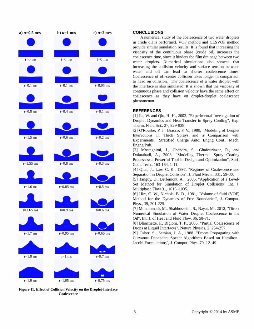
thus coalescence time becomes longer. The influence of droplet
velocity on coalescence is shown in Fig. 11. Based on the
snapshots of the simulation results it is observed that increasing
the droplet velocity reduces the coalescence time. Numerical
results sequence shows that for u= 0.5 and 1 m/s the cylindrical
column is formed during the coalescence process which can be
observed in Figure 2. for u= 2 m/s the coalescence mechanism
is different and droplet merges with the interface from the sides
instead of its bottom.
Time
ms a) B=0 b) B=0.6
0
0.1
0.2
0.3
0.4
0.5
0.9
1.4
1.7
Figure 5. Comparison of Head-On and Off-Center Collision of Two
Water Droplets in Oil (R=100μm, We=16.07)

6 Copyright © 2014 by ASME
Time
ms
a) σ = 0.014
N/m
b) σ = 0.028
N/m
c) σ = 0.056
N/m
0
0.1
0.2
0.3
0.4
0.5
0.9
1.4
1.7
Figure 6. Effect of Surface Tension on the Coalescence of Two
Droplets (R=100μm, (a). We=32.14, (b). We=16.07, (c). We=8.03)
Time
ms a) urel=1.5 m/s b) urel=3 m/s
0
0.1
0.21
0.24
0.29
0.34
0.9
1.5
1.7
Figure 7. Effect of Collision Velocity (R=100μm, (a). We=16.07,
(b). We=64.28)
7 Copyright © 2014 by ASME
Time
ms a) Water droplets b) Oil droplets
0
0.1
0.2
0.3
0.4
0.5
0.9
1.4
1.7
Figure 8. Coalescence Sequence, a) Water Droplets in the Oil,
b) Oil Droplets in the Water
a) μ=2 cP b) μ=5 cP c) μ=8 cP
t=0 ms t=0 ms t=0 ms
t=0.1 ms t=0.1 ms t=0.1 ms
t=0.7 ms t=0.75 ms t=0.8 ms
t=0.75 ms t=1 ms t=1.5 ms
t=0.8 ms t=1.05 ms t=1.55 ms
t=0.85 ms t=1.1 ms t=1.6 ms
t=0.9 ms t=1.15 ms t=1.65 ms
t=0.95 ms t=1.2 ms t=1.7 ms
t=1 ms t=1.3 ms t=1.8 ms
t=1.1 ms t=1.4 ms t=1.9 ms
Figure 10. Effect of Viscosity on the Droplet -Interface Coalescence
(u=0.5 m/s)
2R
R u
Oil
Water
Figure 9. Schematic of the Computational Domain for
Droplet-Interface Coalescence Simulation
8 Copyright © 2014 by ASME
a) u=0.5 m/s b) u=1 m/s c) u=2 m/s
t=0 ms t=0 ms t=0 ms
t=0.1 ms t=0.1 ms t=0.05 ms
t=0.8 ms t=0.4 ms t=0.1 ms
t=1.5 ms t=0.6 ms t=0.2 ms
t=1.55 ms t=0.8 ms t=0.3 ms
t=1.6 ms t=0.85 ms t=0.5 ms
t=1.65 ms t=0.9 ms t=0.6 ms
t=1.7 ms t=0.95 ms t=0.65 ms
t=1.8 ms t=1 ms t=0.7 ms
t=1.9 ms t=1.05 ms t=0.75 ms
Figure 11. Effect of Collision Velocity on the Droplet-Interface
Coalescence
CONCLUSIONS A numerical study of the coalescence of two water droplets
in crude oil is performed. VOF method and CLSVOF method
provide similar simulation results. It is found that increasing the
viscosity of the continuous phase (crude oil) increases the
coalescence time, since it hinders the film drainage between two
water droplets. Numerical simulations also showed that
increasing the collision velocity and surface tension between
water and oil can lead to shorter coalescence times.
Coalescence of off-center collision takes longer in comparison
to head on collision. The coalescence of a water droplet with
the interface is also simulated. It is shown that the viscosity of
continuous phase and collision velocity have the same effect on
coalescence as they have on droplet-droplet coalescence
phenomenon.
REFERENCES [1] Jia, W. and Qiu, H.-H., 2003, "Experimental Investigation of
Droplet Dynamics and Heat Transfer in Spray Cooling", Exp.
Therm. Fluid Sci., 27, 829-838.
[2] O'Rourke, P. J., Bracco, F. V., 1980, "Modeling of Droplet
Interactions in Thick Sprays and a Comparison with
Experiments." Stratified Charge Auto. Engng Conf., Mech.
Engng Pub.
[3] Mostaghimi, J., Chandra, S., Ghafouriazar, R., and
Dolatabadi, A., 2003, "Modeling Thermal Spray Coating
Processes: a Powerful Tool in Design and Optimization", Surf.
Coat. Tech., 163-164, 1-11.
[4] Qian, J., Law, C. K., 1997, "Regimes of Coalescence and
Separation in Droplet Collision", J. Fluid Mech., 331, 59-80.
[5] Tanguy, D., Berlemont, A., 2005, "Application of a Level-
Set Method for Simulation of Droplet Collisions" Int. J.
Multiphase Flow 31, 1015–1035.
[6] Hirt, C. W., Nichols, B. D., 1981, "Volume of fluid (VOF)
Method for the Dynamics of Free Boundaries", J. Comput.
Phys., 39, 201-225.
[7] Mohammadi, M., Shahhosseini, S., Bayat, M,. 2012, "Direct
Numerical Simulation of Water Droplet Coalescence in the
Oil", Int. J. of Heat and Fluid Flow, 36, 58-71.
[8] Blanchette, F., Bigioni, T, P., 2006, "Partial Coalescence of
Drops at Liquid Interfaces", Nature Physics, 2, 254-257.
[9] Osher, S., Sethian, J. A., 1988, "Fronts Propagating with
Curvature-Dependent Speed: Algorithms Based on Hamilton–
Jacobi Formulations", J. Comput. Phys. 79, 12–49.