Bodywork interface General
23
Scania Truck Bodybuilder 22:10-599 Issue 3 2020-10-23 © Scania CV AB 2020, Sweden 1 (23) General Bodywork interface General Bodywork communication interface The electrical system is based on a number of control units that communicate with each other via a common network. Bodywork functions are controlled by the control units, either by using analogue signals or external CAN network. BCI Note: For full BCI functionality (Bodywork Communication Interface), it is recommended that the vehicle is factory-fitted with the option Bodywork communication interface (BCI) (variant code 5837A). Retrofitting a BCI control unit and cable harness involves very extensive work. Con- tact a Scania dealer for more information. More information on the electrical bodywork interface is found in the following doc- uments: • General information on the bodywork console • Working on the bodywork console • Working with the bodywork central electric unit P9 • Work involving chassis central electric unit P11 Information on the highest permitted current take-out is found in the document Cen- tral electric units. Information on how to remove panels is found in the document Working with the in- strument panel.
-
Upload
khangminh22 -
Category
Documents
-
view
0 -
download
0
Transcript of Bodywork interface General

Bodywork interface
GeneralMore information on the electrical bodywork interface is found in the following doc-uments:• General information on the bodywork console• Working on the bodywork console• Working with the bodywork central electric unit P9• Work involving chassis central electric unit P11
Information on the highest permitted current take-out is found in the document Cen-tral electric units.Information on how to remove panels is found in the document Working with the in-strument panel.
GeneralBodywork communication interfaceThe electrical system is based on a number of control units that communicate with each other via a common network. Bodywork functions are controlled by the control units, either by using analogue signals or external CAN network.
BCINote:For full BCI functionality (Bodywork Communication Interface), it is recommended that the vehicle is factory-fitted with the option Bodywork communication interface (BCI) (variant code 5837A). Retrofitting a BCI control unit and cable harness involves very extensive work. Con-tact a Scania dealer for more information.
Scania Truck Bodybuilder 22:10-599 Issue 3 2020-10-23© Scania CV AB 2020, Sweden 1 (23)

General
Bodywork interface
BCI functionality offers the following possibilities:
• Larger range and more choices for signals and functions.• Access to conditional output signals.• Programming of a number of outputs with optional signals.• Remote control of a number of vehicle functions.• Pre-conditions to select additional functionality such as Automatic neutral and
Remote engine start.• Use of expansion units on the frame, which reduces the number of cables from
cab to frame.• Programming and re-use of logic diagrams in BICT (Bodywork Interface Config-
uration Tool).
The signals and functions available depend on the vehicle specification and year of manufacture. A complete list can be found in the BICT program.
More information on options can be found under the heading Ordering options.
Scania Truck Bodybuilder 22:10-599 Issue 3 2020-10-23© Scania CV AB 2020, Sweden 2 (23)

General
Bodywork interface
4
1
1 32
5
373 9
38
Standard preparations from the factoryThe following preparations are found on all vehicles, see illustration:
Pos. Preparation1 Earth connections in cab.2 Bodywork console with connections adapted to the vehicle’s configuration3 Bodywork central electric unit with supply voltage, relay holder and earth
bus.4 Lead through in cab floor.5 Earth connections on chassis frame.
Scania Truck Bodybuilder 22:10-599 Issue 3 2020-10-23© Scania CV AB 2020, Sweden 3 (23)

EXT switch
Bodywork interface
368 5
16
EXT switchThe EXT switch is a spring-loaded, programmable switch with a symbol and an in-dicator lamp, see illustration.
Some safety-critical remotely activated functions cannot be activated before the EXT switch has been activated. This is a general safety function which is used for a num-ber of bodywork functions. When the indicator lamp in the EXT switch is on, remote activation is possible.
More information can be found in the document EXT switch.
Scania Truck Bodybuilder 22:10-599 Issue 3 2020-10-23© Scania CV AB 2020, Sweden 4 (23)

Ordering options
Bodywork interface
iant codeAAABEF
ith Bodywork
A
er for more
AADC
6
5
7
1
2
4
3
8a 8b
373 8
26
Ordering optionsPos. Option Alternative Var1 Pre-routed cable harness in roof. With 30242 Pre-routed cable harness for switch. With 33143 Bodywork information in the instrument cluster. With 38884 Routed cable harness for bodybuilder. 7-pin 2411
7+7-pin 24117+7+7-pin 2411
5a
a. This option only contains harness-to-harness connectors for FMS. The vehicle must be factory-fitted wcommunication interface (BCI) (variant code 5837A) and associated cable harness.
Preparation FMS, FMS Interface. With 40196b
b. Retrofitting a BCI control unit and cable harness involves very extensive work. Contact a Scania dealinformation.
Bodywork communication interface (BCI). With 58377 Bodywork cable for connecting equipment at the
rear of the frame.2 m 30238 m 302312 m 3023
8a Electrical connector for trailer. 7-pin 664A8b 15-pin 664D
Scania Truck Bodybuilder 22:10-599 Issue 3 2020-10-23© Scania CV AB 2020, Sweden 5 (23)

Earthing
Bodywork interface
372 0
92
Earth connection on chassis frame.
373 9
65
The earth bus is visible from the rear of the bodywork central electric unit.
EarthingThere are 2 earth connections for bodywork functions on the frame and 6 in the cab.
• The earth connections on the frame are located on the inside of the left-hand frame side member. One is located in the front part of the frame side member and one in the rear part.
• The following earth connections are located in the cab:– 2 in the roof shelf– 2 behind the instrument panel in the driver area– 1 behind the main central electric unit– 1 earth bus in bodywork central electric unit P9
More information on earth connections and additional earth connections can be found in the document Earthing and power supply.
Scania Truck Bodybuilder 22:10-599 Issue 3 2020-10-23© Scania CV AB 2020, Sweden 6 (23)

Electric power supply
Bodywork interface
1
2
373 9
79
Different types of voltage supply from the bodywork central electric unit:1. 30 voltage, supply voltage directly from the battery.2. 15 voltage, supply voltage which is activated when the starter lock is in the drive
position.
Electric power supplyElectric power supply in the cabThe electric power supply to bodywork functions in the cab must primarily be sup-plied from bodywork central electric unit P9; see illustration.
30 voltageVoltage supply connection: 24 V voltage directly from the battery’s positive termi-nal. The maximum permitted total fuse size of the 6 fuses is 60 A.
15 voltageVoltage supply connection: 24 V voltage activated in the starter lock's drive mode. The maximum permitted total fuse size of the 6 fuses is 30 A.
More information on the bodywork central electric unit is found in the following doc-uments:
• Central electric units• Working with the bodywork central electric unit P9
Scania Truck Bodybuilder 22:10-599 Issue 3 2020-10-23© Scania CV AB 2020, Sweden 7 (23)

Electric power supply
Bodywork interface
1
2
371 8
81
Location of the chassis central electric unit.1. Chassis central electric unit P11.2. Chassis central electric unit P8.
Electric power supply on the chassisThe electric power supply to bodywork functions on the chassis must primarily be supplied from chassis central electric unit P11; see illustration.
Maximum permitted fuse rating is 250 A.
More information on chassis central electric unit P11 can be found in the following documents:
• Central electric units• Work involving chassis central electric unit P11
Scania Truck Bodybuilder 22:10-599 Issue 3 2020-10-23© Scania CV AB 2020, Sweden 8 (23)

Bodywork central electric unit P9
Bodywork interface
390 8
60
Bodywork central electric unit location.
Bodywork central electric unit P9Bodywork central electric unit P9 contains fuse holders, relay holders and earth con-nections intended to be used for bodywork functions.
Bodywork central electric unit P9 is located on the passenger side under the instru-ment panel, behind the protective casing; see illustration.
More information on the bodywork central electric unit is found in the following doc-uments:
• Central electric units• Working with the bodywork central electric unit P9
More information can be found in the instructional film Access to the bodywork cen-tral electric unit on the Scania Truck Bodybuilder website.
Scania Truck Bodybuilder 22:10-599 Issue 3 2020-10-23© Scania CV AB 2020, Sweden 9 (23)

Bodywork console
Bodywork interface
367 9
36
Bodywork console location.
Bodywork consoleThe bodywork console has brackets for 6 connectors and 4 relay holders. The relay holders are adapted for both power relays and electronic relays. All input signals and output signals in the bodywork console are available to bodybuilders.
The bodywork console is located behind the bodywork central electric unit, see illus-tration.
More information on the bodywork console is found in the following documents:
• General information on the bodywork console.• Working with the bodywork console.
Scania Truck Bodybuilder 22:10-599 Issue 3 2020-10-23© Scania CV AB 2020, Sweden 10 (23)

Bodywork console
Bodywork interface
2
3
1
374 3
04
1. Connector C489.2. Control unit for ICL.3. Control unit for VIS.
Connector C489The C489 connector is compulsory on all vehicles, see illustration. The connector gives access to the following functions:
• Voltage supply for alternator charging (+61) and parking light (+58)• Signals for lighting via the VIS (Visibility System) control unit• Status lamp for trailer tag axle via the control unit for the instrument cluster, ICL
(Instrument Cluster)
More information on connector C489 is found in the document Connector C489 – functions for lighting and signal for alternator charging.
Scania Truck Bodybuilder 22:10-599 Issue 3 2020-10-23© Scania CV AB 2020, Sweden 11 (23)

Bodywork console
Bodywork interface
2
3
1
428
795
1. Connector C234.2. Tachograph, TCO (Tachograph).3. Approximate position of the suspension management system, SMS (Suspension
Management System).
Connector C234Functions for tachograph signals and air suspensionC234 provides access to functions for tachograph signals and air suspension, see il-lustration. The harness-to-harness connector is available for vehicles equipped with air suspension or tachograph.
More information on harness-to-harness connector C234 can be found in the docu-ment Harness-to-harness connector C234 – tachograph signals.
Scania Truck Bodybuilder 22:10-599 Issue 3 2020-10-23© Scania CV AB 2020, Sweden 12 (23)

Bodywork console
Bodywork interface
2 1
428
796
1. Connector C234.2. Control unit for instrument cluster, ICL.
Bodywork information in the instrument cluster, ICLC234 is used to present status from the bodywork in the instrument cluster, ICL; see illustration. The harness-to-harness connector is available for vehicles fitted with the option Bodywork information in the instrument cluster (variant code 3888A). The following status indicators can be displayed in the instrument cluster, ICL:
• Light indications.• Acoustic indications.• Display messages.
More information on the option is found under the heading Ordering options.
More information on harness-to-harness connector C234 can be found in the docu-ment Harness-to-harness connector C234 – tachograph signals.
More information about work with light indications, acoustic indications and display messages can be found in the documents:
• Indications in the instrument cluster, ICL.• Variable information.
Scania Truck Bodybuilder 22:10-599 Issue 3 2020-10-23© Scania CV AB 2020, Sweden 13 (23)

Bodywork console
Bodywork interface
1
23
390 8
77
1. Connector C449.2. Trailer connector C162 for tractors.3. Trailer connector C162 for trucks.
Harness-to-harness connector C449C449 provides access to trailer functions and automatic gearbox, see illustration. The harness-to-harness connector is available for vehicles with automatic gearboxes or the option Trailer connector (variant code 664D), a 15-pin trailer connection.
More information on connector C449 is found in the document Connector C449 – functions for automatic gearbox and trailer connection.
Scania Truck Bodybuilder 22:10-599 Issue 3 2020-10-23© Scania CV AB 2020, Sweden 14 (23)

Bodywork console
Bodywork interface
3
2
1
374 3
02
1. Harness-to-harness connector C259.2. Harness-to-harness connector C493.3. BCI control unit.
Connectors C259 and C493C259 and C493 are used for extended bodywork functions, see illustration. The har-ness-to-harness connectors are available for vehicles with optional BCI functionali-ty.
More information on the option is found under the heading Ordering options.
More information on the connectors is found in the following documents:
• Harness-to-harness connector C259 – BCI-controlled functions.• Harness-to-harness connector C493 – BCI-controlled bodywork functions.
Scania Truck Bodybuilder 22:10-599 Issue 3 2020-10-23© Scania CV AB 2020, Sweden 15 (23)
Cable harness
Bodywork interface
C487
C488
C486
C494
390 8
81a
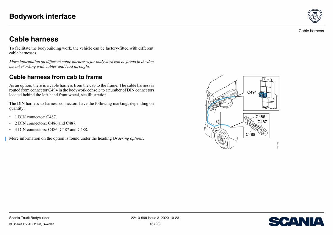
Cable harnessTo facilitate the bodybuilding work, the vehicle can be factory-fitted with different cable harnesses.
More information on different cable harnesses for bodywork can be found in the doc-ument Working with cables and lead throughs.
Cable harness from cab to frameAs an option, there is a cable harness from the cab to the frame. The cable harness is routed from connector C494 in the bodywork console to a number of DIN connectors located behind the left-hand front wheel, see illustration.
The DIN harness-to-harness connectors have the following markings depending on quantity:
• 1 DIN connector: C487.• 2 DIN connectors: C486 and C487.• 3 DIN connectors: C486, C487 and C488.
More information on the option is found under the heading Ordering options.
Scania Truck Bodybuilder 22:10-599 Issue 3 2020-10-23© Scania CV AB 2020, Sweden 16 (23)

Cable harness
Bodywork interface
374 4
53
Extension cable harness on frame including junc-tion boxAn extension cable harness that is connected to the cable harness from harness-to-harness connector C494 using DIN connectors is available as an option; see illustra-tion.
The extension cable harness is supplied with the same number of DIN harness-to-harness connectors as the option Pre-routed cable harness for bodybuilder (variant family 2411). The components are placed in the cab when the vehicle is delivered.
The extension cable harness and junction box are ADR1-classed.
More information on the option is found under the heading Ordering options.
More information on the extension cable harness is found in the document Working with cables and lead throughs.
1. The European Agreement concerning the International Carriage of Dangerous Goods by Road (ADR).
Scania Truck Bodybuilder 22:10-599 Issue 3 2020-10-23© Scania CV AB 2020, Sweden 17 (23)

Cable harness
Bodywork interface
375 3
14
The lead through is located on the passenger side. The illustration shows the location in a left-hand drive vehicle.
Lead through in cab floorIn all trucks, there is a lead through on the passenger side between the cab floor and bulkhead, see illustration. The lead through is dimensioned for a wide range of cable dimensions and is large enough for a connector with a diameter of approx. 70 mm to be passed through it. The lead through is located with the bellows facing out from the cab.
More information is found in the document Working with cables and lead throughs.
Scania Truck Bodybuilder 22:10-599 Issue 3 2020-10-23© Scania CV AB 2020, Sweden 18 (23)

Switch
Bodywork interface
SwitchSwitches in instrument panelThe number of places for bodywork switches in the instrument panel varies depend-ing on the vehicle specification.
Prepared cables with connectors for 4 bodywork switches are available as an option.
More information on the option is found in the document Cable harness for addition-al switches.
Switches in roof shelfDepending on the vehicle specification, it is possible to fit switches in the roof shelf. A cable harness with 10 conductors to the roof shelf, which can be used to connect switches, is available as an option.
More information on the option is found in the document Cable harness for body-work functions in roof shelf.
Switch modulesThe switches have illuminated symbols which can be connected to a dimmer function for background lighting of switches in the instrument panel.
More information on switches is found in the document Switches.
Scania Truck Bodybuilder 22:10-599 Issue 3 2020-10-23© Scania CV AB 2020, Sweden 19 (23)

Indications in instrument cluster (ICL) for bodywork functions
Bodywork interface
Indications in instrument cluster (ICL) for bodywork functionsOption for indications in the instrument cluster gives the option of activating acoustic indications, light indications and display messages for bodywork functions in the in-strument cluster, ICL. Indications in the instrument cluster can be controlled using analogue signals or external CAN network.
More information on the option is found under the heading Ordering options.
The display messages have pre-defined text that cannot be changed.
In front of the light indication positions, there is a removable symbol lens with a sym-bol for each bodywork function. Scania offers symbol lenses with different set of symbols. The parts are available from Scania dealers.
Scania Truck Bodybuilder 22:10-599 Issue 3 2020-10-23© Scania CV AB 2020, Sweden 20 (23)

Indications in instrument cluster (ICL) for bodywork functions
Bodywork interface
The following functionality is available depending on the options:
• Acoustic indications and 2 light indications:– Available on all vehicles.– Can always be controlled using analogue signals.
• 8 light indications1 and display messages:– Requires the option Bodywork communication interface (BCI) (variant code
5837A).• Full functionality for acoustic indications, 8 light indications and display messag-
es:– Requires the options Bodywork communication interface (BCI) (variant code
5837A) and Bodywork information in the instrument cluster (variant code 3888A?).
More information about work with light indications, acoustic indications and display messages can be found in the documents:
• Indications in the instrument cluster, ICL.• Variable information.
1. Depending on vehicle configuration, certain positions may be occupied.
Scania Truck Bodybuilder 22:10-599 Issue 3 2020-10-23© Scania CV AB 2020, Sweden 21 (23)

Indications in instrument cluster (ICL) for bodywork functions
Bodywork interface
EXT
374 4
72
Instrument cluster (ICL)The instrument cluster (ICL) contains the following options:
• Connections to 8 light indication positions1 for light indication. Light indication positions and cable harnesses are fitted at the factory.
• Display messages.• Connection of acoustic indication for various needs.
Adapted symbols and coloursA removable symbol lens is fitted in front of the light indication positions; see illus-tration. Some symbols are pre-printed from the factory based on the vehicle specifi-cation.
The bodybuilder can use their own symbols or text. Sheets of finished symbols can be purchased from Scania dealers.
The parameters for the light indications in the instrument cluster (ICL) can be set to show a blue, yellow, green or red light depending on the lamp’s position. The setting of the parameters is done by using SDP3 for bodybuilders.
Information on renewing the symbol lens can be found in the document Indications in the instrument cluster, ICL.
1. Depending on vehicle configuration, certain positions may be occupied.
Scania Truck Bodybuilder 22:10-599 Issue 3 2020-10-23© Scania CV AB 2020, Sweden 22 (23)

External CAN network, CAN bodywork interface
Bodywork interface
External CAN network, CAN bodywork in-terfaceA great advantage with the bodywork interface is the possibility to connect to the ve-hicle’s CAN interface via the BCI control unit. By using an external CAN network, connections can be simplified, especially those with multiple functions.
An external CAN network makes it possible to control functionality by reading in-formation (output signals from the vehicle) and sending information (input signals to the vehicle). Information sent from the vehicle via an external CAN network includes not only the signals in the existing connectors but also much more.
Connect an external CAN network via connector C493 in the bodywork console. CAN interface for bodywork is included in the option Bodywork communication in-terface (BCI) (variant code 5837A), which can be ordered from the factory.
More information on the CAN interface can be found in the CAN interface for body-work document.
Harness-to-harness connector C137The FMS standard (Fleet Management System) is an open, shared interface devel-oped by several truck manufacturers.
Connector C137 gives access to signals for FMS and is located behind the main cen-tral electric unit in the instrument panel.
More information on the option is found under the heading Ordering options.
Scania Truck Bodybuilder 22:10-599 Issue 3 2020-10-23© Scania CV AB 2020, Sweden 23 (23)