Network Interface Shell Installation and User Guide - Nokia ...
Upload
khangminh22Category
view
6download
0
Print Tuesday, February 13, 2018 13:32:00
Original Operating Manual
User Interface
1.951.3041-V10 02/18
JULABO GmbH 77960 Seelbach / Germany Phone +49 (0) 7823 / 51-0 Fax +49 (0) 7823 / 24 91 [email protected] www.julabo.com

Table of Contents
2 2.13.2018
Printed in Germany Changes without prior notification reserved
Important: keep original operating manual for future use

USER INTERFACE
2.13.2018 3
Table of Contents
Table of Contents ............................................................................................................................................. 3
1. Initial Operation......................................................................................................................................... 6
1.1. Connecting to power supply ........................................................................................................... 6
1.2. Switching the unit on / selecting language ..................................................................................... 6
2. Normal display .......................................................................................................................................... 7
2.1. Set temperature............................................................................................................................ 11
2.2. Start / Stop ........................................................................................................................... 11
3. Main menu view ...................................................................................................................................... 12
3.1. Available keys in the main menu .................................................................................................. 12
3.2. Unit Access/Safety Settings ................................................................................................ 13
3.2.1. Administrator - Managing Access to the Unit..................................................................... 13
3.2.2. User Groups - Managing Access to the Unit ..................................................................... 16
4. "Settings" menu ...................................................................................................................................... 18
4.1. "Language" menu ......................................................................................................................... 18
4.2. "Autostart" menu .......................................................................................................................... 19
4.3. "Units" menu ................................................................................................................................. 19
4.4. Menu Customize Home display ................................................................................................... 20
4.5. "Date / time" menu ....................................................................................................................... 21
4.6. "Colors" menu .............................................................................................................................. 21
4.7. "Keypad tones" menu ................................................................................................................... 22
4.8. “Info“ menu ................................................................................................................................... 22
4.9. Max. current consumption menu .................................................................................................. 22
5. "Determine thermodynamics" menu ....................................................................................................... 23
5.1. "Adjust controller" menu ............................................................................................................... 23
5.1.1. "Self-tune" menu ................................................................................................................ 24
5.1.2. Bandlimit Selftune .............................................................................................................. 24
5.1.3. "Adjust control performance" menu ................................................................................... 25
5.1.4. "Adjust limits" menu ........................................................................................................... 28
5.2. "Adjust pump" menu ..................................................................................................................... 30
5.2.1. „Type“ menu ....................................................................................................................... 30 5.2.1.1. Type „Stage control“ .......................................................................................... 30 5.2.1.2. Type „Pressure control“ ..................................................................................... 31 5.2.1.3. Type „Flow rate Control“ .................................................................................... 32
5.2.2. "Pump mode" menu ........................................................................................................... 32
6. "Using a programmer" menu .................................................................................................................. 34
6.1. "Edit a profile" menu ..................................................................................................................... 35
6.1.1. Add ..................................................................................................................................... 36
6.1.2. Edit ..................................................................................................................................... 37

Table of Contents
4 2.13.2018
6.1.3. Delete .................................................................................................................................37
6.1.4. Insert ..................................................................................................................................37
6.2. "Starting a profile" menu...............................................................................................................38
6.3. "Using a programmer series" menu .............................................................................................40
7. "Recording data" menu ...........................................................................................................................42
7.1. JULABO Service – Online remote diagnosis ...............................................................................44
8. "Service" menu .......................................................................................................................................45
9. "Safety adjustments" menu ....................................................................................................................46
9.1. “Temperature limits“ menu ...........................................................................................................46
9.1.1. Minimum and maximum setpoint .......................................................................................46
9.1.2. Subtemperature, Overtemperature ....................................................................................46
9.1.3. Allowed temperature gradient per minute ..........................................................................47
9.2. “Pressure limits“ menu .................................................................................................................48
9.2.1. Permissible Pumpstage .....................................................................................................48
9.2.2. Permissible pressure Setpoint ...........................................................................................48
9.2.3. Upper and lower pressure warning limit ............................................................................49
9.2.4. Upper and lower pressure warning limit ............................................................................50
9.3. Flow limits ...................................................................................................................................50
9.3.1. Min. and max. flow setpoint ............................................................................................50
9.3.2. Upper and lower flow warning limit ...............................................................................51
10. "Connect unit" menu ...............................................................................................................................52
10.1. "Remote control" menu ................................................................................................................52
10.2. „External setpoint“ menu ..............................................................................................................53
10.3. "Actuating variable" menu ............................................................................................................54
10.4. "Digital interfaces" menu ..............................................................................................................55
10.4.1. RS232 ................................................................................................................................55
10.4.2. Watchdog ...........................................................................................................................55
10.4.3. Ethernet ..............................................................................................................................59 Ethernet menu ...................................................................................................................59 Network-based connection ................................................................................................62 Creating a Direct Connection between and PC ............................................63
10.5. "Analog interfaces" menu .............................................................................................................65
10.5.1. Alarm output .......................................................................................................................65
10.5.2. JULABO Sensor Pressure / Flow.......................................................................................66
10.5.3. EXT Pt100 2 (accessory) ...................................................................................................69
10.5.4. Analog module (optional) ...................................................................................................70 Standby connector .............................................................................................................71 REG+E-PROG connector ..................................................................................................72
11. "Install unit" menu ...................................................................................................................................79
11.1. "Fill unit" menu (refilling) ...............................................................................................................79

USER INTERFACE
2.13.2018 5
11.2. "Empty the unit" menu .................................................................................................................. 81
11.3. "Adjust sensors" menu ................................................................................................................. 83
11.4. "Reset unit" menu ......................................................................................................................... 86
11.5. "Unit name" menu ........................................................................................................................ 87
11.6. Save/load parameters .................................................................................................................. 87
11.7. Configure unit ............................................................................................................................... 89
11.8. Firmware update .......................................................................................................................... 91
12. Error messages, fault causes, remedies ................................................................................................ 92
13. Remote control ....................................................................................................................................... 94
13.1. Setup for remote control ............................................................................................................... 94
13.2. Communication with a PC or a superordinated data system ....................................................... 95
13.3. List of commands ......................................................................................................................... 96
13.3.1. in commands ...................................................................................................................... 96
13.3.2. out commands ................................................................................................................... 99
13.4. Status messages ........................................................................................................................ 101
13.4.1. Status messages as reply to sent commands ................................................................. 101
14. Communication via Modbus TCP/IP..................................................................................................... 102
14.1. Datatypes ................................................................................................................................... 102
14.1.1. Used Datatypes ............................................................................................................... 102
14.1.2. Data Encoding ................................................................................................................. 102
14.2. Error Handling ............................................................................................................................ 102
14.3. Holding-Registers ....................................................................................................................... 103
14.3.1. Function-Codes ................................................................................................................ 103
14.3.2. Register table ................................................................................................................... 103
14.4. Input-Registers ........................................................................................................................... 106
14.4.1. Function-Codes ................................................................................................................ 106
14.4.2. Register-Table ................................................................................................................. 106
15. Error messages .................................................................................................................................... 108
15.1. Alarm messages......................................................................................................................... 109
Error in module configurations ..................................................................................................................... 110
15.2. Warning messages..................................................................................................................... 115
16. Appendix: Peer-to-peer remote display operation of ® ............................................... 118
with CerHost via Ethernet ....................................................................................................................... 118
16.1. Connect the to the LAN port of your PC or tablet .................................................. 118
16.2. Adjust the Network settings on your PC .................................................................................... 118
16.3. Adjust settings on the ............................................................................................ 120
16.4. Connect to the with CerHost .................................................................................. 120

Initial Operation
6 2.13.2018
1. Initial Operation
1.1. Connecting to power supply
Caution: • This device may be attached to protected earth (PE) mains
power outlets only!
• The mains plug serves as a reliable way to disconnect the unit from its power supply for safety reasons and must be readily accessible at all times.
• Do not attempt to use the unit if the power cable is damaged! • Regularly inspect the power cable for damage. • No liability for improper power connection!
Compare the available mains voltage and mains frequency with the
specifications on the type label.
• Connect the mains plug to a protected earth (PE) power supply socket!
1.2. Switching the unit on / selecting language
Refer to >Settings menu< on
page 18 for language selection.
To switch the unit on: Use the mains switch to bring the unit into operation. The integrated lamp indicates that the power is on. As initialization proceeds, the unit will assume the start positions and emit mechanical sounds. The unit's name and voltage type are displayed briefly.
The unit will enter the same operating mode that it was in before shutdown, i.e. manual model (operation with the unit's controls or remote control (operation via PC).

USER INTERFACE
2.13.2018 7
2. Normal display
Normal display: The normal display contains important values and functions.
Adjust the high temperature cut-off by slowly turning the dial with a screwdriver. The exact value will appear on the display.
Note: The order and availability of values 9 to 12 will depend on the settings in the > Customize Home display < menu. Page 20 The factory state is shown here.
1 Date / time
2 Status: on/Standby / Warning 3 Fill level indicator 4 External temperature sensor value 5 Current power (X% heating, -X% cooling) 6 Selected temperature control (internal/external) 7 Actual liquid temperature 8 Selected max. pressure and actual pressure 9 Selected high temperature cut-off ( page 46) 10 Selected low temperature cut-off 11 High temperature cut-off (TANK) 12 High temperature cut-off (RESERVOIR)
Cooling icon Blinking or continuous
Heating icon Blinking or continuous
< Setpoint button
Adjust normal display
Call up main menu
Start/Stop button
State information Examples:
Remote control mode through interface ( page 94)
A storage medium is inside the unit. ( page 42)
The unit is connected to a PC via ethernet. ( page 55)
Access to unit is blocked ( page 13)
Remote control mode via "Wireless Temp"

Normal display
8 2.13.2018
Warning
• The > TANK < high temperature cut-off should be set to 15 °C above the working temperature setpoint.
• The > RESERVOIR < high temperature cut-off must be set to at least 25 °C below the heattransfer liquid's flashpoint.
Adjust the normal display
You can adjust the normal display to your requirements by pressing the >Display< key.
You may select the colors used in the normal display's chart. >Settings menu< page 18.
Chart shows the progression of the setpoint and actual temperature.
Displays during errors
ALARM red > WARNING yel low >
Help is always accessible through
the icons or .
Touch the icon and a list of errors will be displayed.
The unit provides straightforward and intuitive operation on the color TFT display even during errors. Error messages are divided into two categories: >ALARM< and >WARNING<
Date and time when the error appeared are stored and displayed. If possible, this data will also be stored during removal of the error. Example code

USER INTERFACE
2.13.2018 9
ALARM display Error messages are displayed in a red box.
Resolution for example E14:
Touch the red box to
mute the alarm.
Press < > button for help text.
The module and the configuration are displayed. Follow the instructions in the help text.
Press < > button.
Press < > button again for help text.
Press < > button. .
Another error message (E108) appears and describes a pathway for overcoming the alarm.
Press < > button for help text.
Follow the instructions in the help text. The unit is now ready to continue operation.
The unit switches to „Standby“. Heater, refrigeration unit and circulation pump are switched off.
Error message (E 14) remains although the safety temperature has been raised.
A <Reset> is not permitted in this case because, according to
NAMUR, this condition must be resolved via hardware. Errors not subject to this regulation are resolved via <Reset>.
Not all alarms may be removed on-site. List of all error messages see page 108

Normal display
10 2.13.2018
WARNING display:
A warning does not result in shutdown of the heater, refrigeration unit, and circulation pump. The unit provides the option of defining some warning limits independently, such as limits for pump pressure, limits for over-temperature and under-temperature. If one of these limits is exceeded, a warning (ticker and signal) will continue for as long as the cause is active.
The yellow attention symbol will remain. It will draw attention to events that occurred during absence of the operating personnel. The events are stored in a list of errors.
Warnings are displayed as a ticker in the status line.
Example: Warning 40
Touch the icon to mute the signal.
Touch or and a list of errors will be displayed.
Buttons in the list -
Press the < > button for help text.
Press < > to delete an error message from the list. The 10 most recent events are shown.
The complete list may be viewed in the password-protected service menu.
page 45
Use the keys to view the list.
Use the key to exit the list. The yellow Attention icon " "
is reset to " ".

USER INTERFACE
2.13.2018 11
2.1. Set temperature Select setpoint
Setpoint button
Input panel (example: 25.00 °C)
The green keys display the most recently selected values.
Input keys
Keys 0 to 9 (digits keypad)
Decimal point button
Minus/plus button
Backspace key
Exit window without changes
Input/confirm entry
2.2. Start / Stop
Press Start/Stop button The start-up phase can last up to 30 seconds.
The unit switches to „On“ and runs through a start-up phase, during which various parameters are checked and/or adjusted. When the ticker is no longer displayed, the unit operates normally.

Main menu view
12 2.13.2018
3. Main menu view
Select menu
3.1. Available keys in the main menu
Block access to unit / password-protected actions.
Go back one menu level.
Home (return to normal display).
Retrieve help menu Press < > and then press the desired entry in the menu.
Indicates available submenu.
Digits keypad
Keys 0 to 9 (digits keypad)
Exit window without changes
Move cursor: left / right
Example: Date input boxes
Backspace key
Input/confirm entry
Example: Input box with temperature value -10 °C
Decimal point button
Minus/plus button

USER INTERFACE
2.13.2018 13
3.2. Unit Access/Safety Settings
have full rights.
Administrator assignment of password and access rights.
Without an entry in the menu, the unit can be operated by any authorized person. You can change the unit's safety settings in this menu. The authorized users and user rights can be restricted. An >Administrator< is authorized to manage access to the unit. He can approve differing rights for two groups of users. Access is always password-protected. A six-digit password was set at the factory so the administrator can gain initial access. Six zeros: 000000
Refer to page 16 to change the administrator password.
3.2.1. Administrator - Managing Access to the Unit
Press the key in > Main menu <.
The >Unit account< menu is displayed.
Press the key
Enter the administrator password.
>Lock unit< >Idle timer< Description page 17
Light gray buttons are blocked.
Press >Logout< to re-enable access to the unit.
Main menu view
14 2.13.2018
Press the key
Enter administrator password
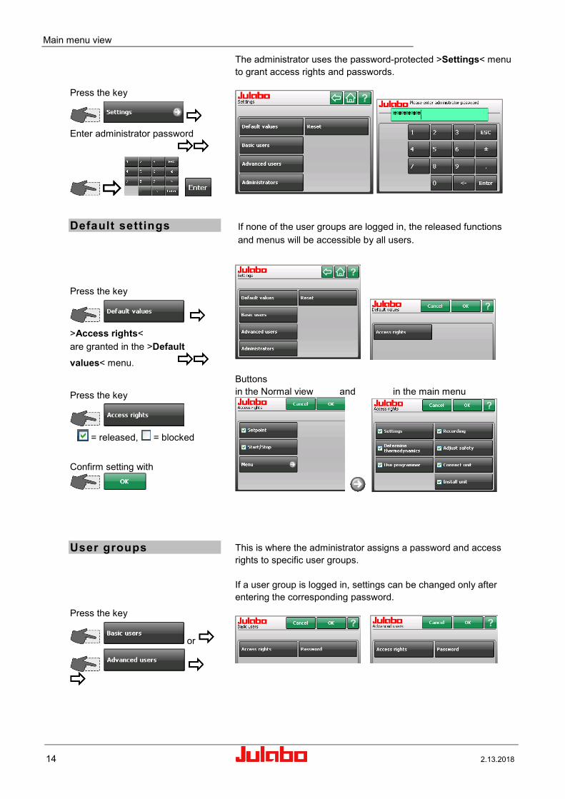
The administrator uses the password-protected >Settings< menu to grant access rights and passwords.
Default settings
Press the key
>Access rights< are granted in the >Default values< menu.
Press the key
= released, = blocked
Confirm setting with
If none of the user groups are logged in, the released functions and menus will be accessible by all users.
Buttons in the Normal view and in the main menu
User groups Press the key
or
This is where the administrator assigns a password and access rights to specific user groups. If a user group is logged in, settings can be changed only after entering the corresponding password.

USER INTERFACE
2.13.2018 15
Press the key
The user is asked to enter a new password and reenter the password for confirmation.
Confirm setting with
Example: Basic users
Example: 4-digit password for > Basic users <
Press the key
Use the check box to grant
or deny access rights to user groups.
Confirm setting with
Basic users Advanced users Factory settings
Reset
Press the key
.
Press this button to reset all access rights to factory settings.

Main menu view
16 2.13.2018
Administrator
Change Password:
Press the key
The user is asked to enter a new password and reenter the password for confirmation.
ATTENTION: Record the new password in a secure place. It will not be possible to access the unit without this password. The factory password will be overwritten.
Forget your password? This can be resolved only through the >Service menu< Page 45. The authorized service person can delete the stored password and reset it back to the factory setting.
3.2.2. User Groups - Managing Access to the Unit
Users can sign on with the password that has been assigned to them. After login, all settings approved for the relevant user group will be accessible by everyone without reentering the password. Press "Lock unit" to prevent misuse.
Press the key in > Main menu <.
The >Unit account< menu is displayed.
Light gray buttons are blocked.
Press this button to login
Enter the password
Access to the unit is enabled for the respective user group. Permitted adjustments can now be performed.

USER INTERFACE
2.13.2018 17
Block unit access immediately Press the key
Block with time delay. Press the key
Set time.
Press the key
"Deactivate" time or "Edit" time.
Enter the desired time here, after which the unit will be blocked if no additional entries are made. Example: 5 minutes.
The current setting is shown on the button and will remain until changed.
The unit will automatically switch to the normal display.
Press to enter password
If someone attempts to use a locked unit, a window will open to notify the user that the unit is locked. Example:
Access to the unit can be restored by entering the password of the user group that locked the unit or the administrator password. If an incorrect user group password is entered three times in a row, the administrator password will be required to enable the unit.
Enable access to the unit. Press Logout to confirm.
After pressing >Logout<, access to the unit is re-enabled.

"Settings" menu
18 2.13.2018
4. "Settings" menu Select in the main menu
Select menu here
The buttons will display the current settings or indicate availability of a submenu:
.
Example: Call up the >Units< Help menu.
Press the < > button and then press the >Units< button in the menu.
4.1. "Language" menu
Select language.

USER INTERFACE
2.13.2018 19
4.2. "Autostart" menu
Switch Autostart on/off
Allows the direct start of the temperature control systems via the mains power switch.
>Autostart< Note: The temperature system has been configured and supplied by JULABO according to N.A.M.U.R. recommendations. This means for the start mode, that the unit must enter a safe operating state after a power failure (non-automatic start mode). This safe operating state is indicated by "OFF", on the TFT-Display. A complete shutdown of the main functional elements such as heater and circulation pump is effected simultaneously. Using the AUTOSTART function is only possible when a set-point is set via >TFT Display< and >EPROG-input<. Should such a safety standard not be required, the AUTOSTART function (automatic start mode) may be activated, thus allowing the start of the instrument directly by pressing the mains power switch or using a timer.
4.3. "Units" menu
The buttons will display the current settings.
Select the temperature units
°C or °F
Select pressure units
bar or psi
Select flow rate units
l/m or gpm

"Settings" menu
20 2.13.2018
4.4. Menu Customize Home display Two paths to the submenu > Customize Home display <.
1. Via
2. Touch the field.
The current setting is displayed on the keypad.
Choose value X. Example: value 1
Choice of displayable values.
Push for further values.
Choose value and automatic return to > Customize Home display <.
Or push and leave the display without changes.
Active key light green.
or
The sequence and choice of the values in the orange field can be changed. The partial area in the lower right is a keypad which turns
orange when touched.
Example: Value 1 / Flow rate Message in case of incorrect choice.
Setting via
Whether >Pressure< or >Flow rate< are settable, depends on the setting of >JULABO Sensor Pres./Flow<.

USER INTERFACE
2.13.2018 21
(page 66)
4.5. "Date / time" menu
Set date / time
Enter values with digits keypad.
Various options each are available for >Format< and
>Separator<.
4.6. "Colors" menu
Select colors
You may select the colors used in the normal display's chart.
Use to change the settings in the selected submenu.
Red
Green (example at left, setpoint)
Blue
Confirm setting with .
In this way you can choose custom colors from the RGB color
palette.

"Settings" menu
22 2.13.2018
4.7. "Keypad tones" menu
Switch tones on/off
An audible tone will be emitted each time you press a button.
Three different tone lengths are available.
4.8. “Info“ menu Select Info
Information on module configuratioin.
Examples
4.9. Max. current consumption menu
The buttons will display the current setting.
Enter values with digits keypad.
The maximum current consumption of the unit is preset at the factory. An adjustment of this setting may become necessary if the fuse rating of the building installation is lower than the presetting.
Setting range see display of unit.

USER INTERFACE
2.13.2018 23
5. "Determine thermodynamics" menu Select in the main menu
Select menu here
indicates available submenu.
5.1. "Adjust controller" menu
Select menu
The buttons will display the current settings or indicate availability of a
submenu: .
Select desired control type
temperature-control units let you choose between internal (inside the heat exchanger) or external (directly at the application or temp.-control loop)
temperature control.
Your selection is shown in the normal display.

"Determine thermodynamics" menu
24 2.13.2018
5.1.1. "Self-tune" menu
Select setting
During self-tuning, the controlled process's parameters Xp, Tn, and Tv will be automatically determined and stored.
Available parameters:
Off - no self-tuning The control parameters of the most recent identification are stored and will be used for control purposes.
Once - one-time self-tuning
The unit will perform a one-time identification of the controlled process each time the unit is started with the button or via the start command through the interface.
Always - continuous self-tuning The circulator will identify the controlled process at each setpoint jump. Select this option only if the controlled system changes continuously.
5.1.2. Bandlimit Selftune
During self-tuning, it is important to prevent the speed of the temperature change in the rapid internal system ( ) from greatly exceeding the speed of the temperature change in the slower external application. A bandlimit during self-tuning ensures that temperature changes in the unit (small mass) and in the application (usually larger masses) proceed uniformly. This applies to the heat up and cool down phases. The maximum permissible temperature difference is defined with the value >Bandlimit selftune<.
As long as >Bandlimit selftune< is engaged, the bandlimit will be switched off during external control (see >Lower/upper bandlimit<, page 29).
Set value
Example: 50 K
Setting range see display of unit.

USER INTERFACE
2.13.2018 25
5.1.3. "Adjust control performance" menu
Select menu
indicates available submenu.
Preparing for external control: Connect the Pt100 external sensor to the socket in the socket panel. It is normally not necessary to calibrate the sensor. In special situations, a three-point calibration, for example, can be performed with the "Adjust sensors" function (see page 83).
The buttons will display the current settings.
Select parameters
Set new values.
Internal parameters External parameters
or
Internal/external control parameters In most cases, the factory-set control parameters will be adequate for achieving an optimal temperature sequence in the item being controlled. Adjustable control parameters give you the ability to adapt to unusual processes.
Setting range: internal/external 0.1 ... 99.9 K
Proportional range >Xp< The proportional range is the temperature range below the setpoint in which the heating capacity is controlled from 100 % to 0 %.
Setting range: internal/external 0 ...10000 s
Reset time >Tn< (integral proportion) Compensation for the control deviation that remains due to the proportional controller. Reset times that are too small may lead to instability. Reset times that are too large will make compensation of the control difference unnecessarily long.
Setting range: internal/external 0 ... 1000 s
Rate time >Tv< (differential proportion) The differential proportion shortens the adjustment time. If the rate time is too small, equalization of an interference value will be extended and you will experience large overshoots when approaching a setpoint. If the rate times are too great, you may experience instability (oscillations).
Setting range: 0.1 ... 99.9 K
Proportional range >Xpu< The Xpu proportional range of the underlying controller is needed only for external control.

"Determine thermodynamics" menu
26 2.13.2018
A Standard B Aperiodic C Temperature stability D Setpoint E Temperature ramp
> Dynamic < This parameter influences the temperature sequence only during internal control.
Available parameters:
Standard The temperature will climb faster, but may overshoot by up to 5%. If a ramp is defined, the temperature sequence will largely follow this ramp.
Aperiodic. Temperature will increase with time offset (no overshoots).
Both settings will achieve adequate temperature stability after approximately the same amount of time.
Setting range: 0.00 to 5.00
S Setpoint Ext External temperature Int Internal temperature
>CoSpeed factor< This parameter will influence the temperature sequence only with external control. The setting influences calculation of the control parameters during identification, thereby influencing control behavior.

USER INTERFACE
2.13.2018 27
Optimization tips for PID control parameters The progression of the control object's temperature over time can indicate improperly adjusted control parameters.
Optimal
Improper adjustment may lead to the following heat-up curves:
Xp too small
Tv/Tn too small
Xp too large or Tv too large
Tv/Tn too large or Xp too large
"Determine thermodynamics" menu
28 2.13.2018
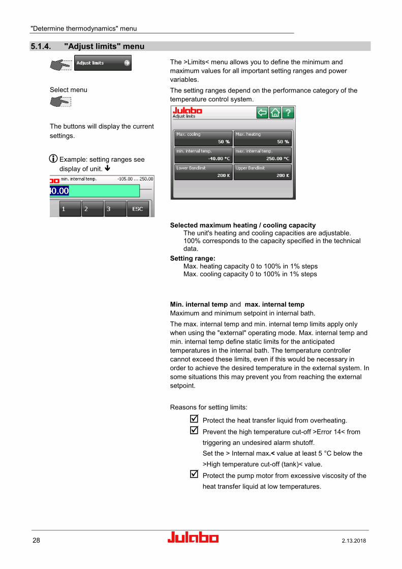
5.1.4. "Adjust limits" menu
Select menu
The buttons will display the current settings.
Example: setting ranges see display of unit.
The >Limits< menu allows you to define the minimum and maximum values for all important setting ranges and power variables. The setting ranges depend on the performance category of the temperature control system.
Selected maximum heating / cooling capacity The unit's heating and cooling capacities are adjustable. 100% corresponds to the capacity specified in the technical data.
Setting range: Max. heating capacity 0 to 100% in 1% steps Max. cooling capacity 0 to 100% in 1% steps
Min. internal temp and max. internal temp Maximum and minimum setpoint in internal bath. The max. internal temp and min. internal temp limits apply only when using the "external" operating mode. Max. internal temp and min. internal temp define static limits for the anticipated temperatures in the internal bath. The temperature controller cannot exceed these limits, even if this would be necessary in order to achieve the desired temperature in the external system. In some situations this may prevent you from reaching the external setpoint. Reasons for setting limits:
Protect the heat transfer liquid from overheating.
Prevent the high temperature cut-off >Error 14< from triggering an undesired alarm shutoff. Set the > Internal max.< value at least 5 °C below the >High temperature cut-off (tank)< value.
Protect the pump motor from excessive viscosity of the heat transfer liquid at low temperatures.

USER INTERFACE
2.13.2018 29
Legend: A Internal bath
B External system
C Upper bandlimit
D Lower bandlimit
Lower bandlimit and Upper bandlimit Bandlimits are active during external control. Various settings are possible for the heat-up and cool-down phases as required. Setting range: 0 °C ... 200 K
> Upper bandlimit < and > Lower bandlimit < define the maximum permissible temperature difference between the internal bath and the external system during the heat-up or cool-down phase, respectively. During the heat-up phase, this difference value is always added to the current external temperature. During the cool-down phase, the difference value is subtracted. Reasons for setting limits: Protect the object being controlled with gentle temperature
control. Protect glass reactors or other objects from thermal tension.
As long as >Bandlimit selftune< is engaged, the bandlimit will be switched off during external control (see page 24 ).

"Determine thermodynamics" menu
30 2.13.2018
5.2. "Adjust pump" menu Select
The buttons will display the current settings.
Select the pressure display in the Units menu: psi or bar Page 19
5.2.1. „Type“ menu Select
Attention Observe the external consumer's pressure limits! Pressure limits refer to page 48 Set your value here.
Type of pump control.
Pump control can be realized in different ways.
5.2.1.1. Type „Stage control“ Select
Change presetting in the respective submenu.
Select
Example: Stage 3
Adjustable in 5 stages. The number of stages depends on the temperature-control system's performance class and is displayed in the Pump Stage menu. Each stage increases pressure in the system.
A30 has only one Pumpstage.

USER INTERFACE
2.13.2018 31
Notice
Settings of setpoint limits for >Pumpstage< and >Limit Pressure< are active.
Examples:
If the >Limit Pressure< is exceeded at >stage 3< an alarm including the cut-off of the unit is activated!
5.2.1.2. Type „Pressure control“
Select .
Set pressure setpoint.
Example „0.5“
Setpoint limits refer to page 48
The setting ranges depend on the performance category of the temperature control system. Example: see display of unit.
Settings in the >" Adjust safety " menu< will influence these values. If a >Setpoint limit< is set, you will not be able to exceed or fall below this value, respectively. You will receive a message stating "Value is too small or too large"
Example: The displayed value, in this case „Max:0.65“, always refers to the next higher limit.

"Determine thermodynamics" menu
32 2.13.2018
5.2.1.3. Type „Flow rate Control“ Select
Set value.
Note
Check the selected pressure limits! (Page 48)
The selected pressure limits are monitored during flow control as well.
A high flow rate may exceed these limits and cause the unit to shut down.
The flow rate is infinitely adjustable and is actively controlled.
The setting range depend on the performance category of the temperature control system. Example: Setting range see display of unit.
Example: 12.00 l/min
Refer to the operating manual of the utilized flow control unit
for additional notes on possible flow rates.
5.2.2. "Pump Mode" menu Select
>Pump Auto< The pump is controlled via the start/stop button or via the interface.
>Pump on< Pump runs continuously.
>Pump after-run< You must select the pump’s after-running time.
>Pump after-run<
Set time.
Example: 5 minutes
hh:mm:ss

USER INTERFACE
2.13.2018 33
5.2.3. "Adjust control performance" menu Select
For
and
each of parameter Xp (Proportional range) and Tn (Reset time) can be set.

"Using a programmer" menu
34 2.13.2018
6. "Using a programmer" menu
Select in the main menu
.
Setpoint = green
Actual value = red
A programmer makes it easy to quickly program setpoint temperature profiles. A profile is a series of temperature setpoints. A profile consists of several individual steps. Each step is defined according to a length of time (t:) or gradient (°/t) and target temperature. The target temperature is the setpoint that will be reached when the step is complete. The programmer references time and temper-ature difference in a step to calculate a temperature ramp (1). Attention: If the time specification is too short, there will not be enough time to reach the setpoint. The programmer contains an easy way to handle this situation. If a step time of 00:00:00 is entered, the setpoint will "jump" (2) to the target temperature as quickly as possible. The profile will continue with the next step only after reaching the specified temperature (±0.2 °C). Eight profiles with up to 60 steps each can be stored. The Standard and Gradient settings can be used together in a single profile.
Edit Profile: Create or edit a temperature profile.
Start Profile: Start a temperature profile. Use programmer series: This feature allows you to set a series so a certain profile will run at the same time on several different days.

USER INTERFACE
2.13.2018 35
6.1. "Edit a profile" menu Create a new profile.
Press
.
Example:
Select profile 3 from profiles 1 to 8
and
You will use the following four menus to create a profile.
Edit: Edit the currently selected step. Change setpoint / duration.
Add: Adds a new step to the profile at the end of the list.
Delete: Delete the currently selected step.
Insert: Adds a step to the profile in front of the currently selected step.
Import or export the profile to or from an external data carrier.
Scroll up and down in the >Setpoint / Duration< list or select the desired line by touching it with your finger.
Diagram of the selected profile.

"Using a programmer" menu
36 2.13.2018
6.1.1. Add Select
Now select Standard or Gradient.
Standard: Set setpoint and duration.
Gradient: Set target temperature and gradient.
Settings in the "Limits" menu will constrain the setting range. (Chapter 5.1.4. "Adjust limits" menu )
Set setpoint and duration
and
20.00 °C --- 00:15:30
35.00 °C --- 00:10:00
35.00 °C --- 02:00:00
Examples: Standard Temperature setpoint [°C/°F] and duration [hh:mm:ss]
Set setpoint and gradient
and
60.00 °C --- 2.5 °C/min
Examples: Gradient Temperature [°C/°F] and Gradient [°C/min]
Attention: See Chapter „ 9.2. “Setpoint limits“ menu“ If the maximum temperature gradient per minute for heating / cooling is enabled, the range here is restricted.
The Standard and Gradient settings can be used together in a single profile.
Example: Step 5 of 5 steps is selected.
5/5 The currently selected step is saved.

USER INTERFACE
2.13.2018 37
6.1.2. Edit
Use to select step.
Press
Set new values.
Edit the currently selected step.
Set new values.
6.1.3. Delete
Use to select step.
Press
Delete the currently selected step.
6.1.4. Insert
Use to select step.
Press.
Set new values.
Insert a step in front of the selected step.

"Using a programmer" menu
38 2.13.2018
6.2. "Starting a profile" menu Select.
Example: Select profile 3
and
The buttons will display the current settings.
End of profile: Status at the end of the profile (see page 40 for description).
Repeats: A profile can be repeated up to 99 times.
Start time:
Start immediately with or define start time.
1 run + 2 repetitions (Loops) = 3 runs
Refer to page 21 for date and time format.
Select
.
Set values.
Year / Month / Day Hour / Minute / Seconds

USER INTERFACE
2.13.2018 39
The >Start time< button will then display the current setting.
Press for normal view. The normal display will show the current time, the selected start time, and the remaining time until starting.
Before starting: This area at the lower left is a button that turns orange when touched.
New buttons will then appear in the center of the screen.
You can still exit the start phase by pressing >Abort<.
After starting: The following values will be shown at the bottom left of the normal display: The computed setpoint The current step's remaining time Current step / remaining number of runs Time remaining in profile
This area at the lower left is a button that turns orange when touched.
New buttons will then appear in the center of the screen.
Pause/Resume "Pause" will stop the progression of a profile. Press "Resume" to restart. Abort The program will end; return to normal display.
Edit Refer to >Edit a profile< on page 34.
Pause/Resume The setpoint and both remaining times will be paused. Visible on the display: Remaining time: Pause

"Using a programmer" menu
40 2.13.2018
End behavior
Here you can decide whether the unit will switch OFF at the end of a program or whether temperature control will continue. You also select the working temperature setpoint to be used at this time.
Standby The unit will turn >OFF< at the end of the program.
PG setpoint At the end of the program, the unit will continue to run with the final step's setpoint.
Press to end or start a new program.
Start setpoint At the end of the program, the unit will continue to run with the first step's setpoint.
6.3. "Using a programmer series" menu Select
Use this function to run a profile at the same time on a series of days.
The buttons will display the current settings.
Press a button
Examples:
Set the series start date.
and
Set the series end date.
and
Day / Month / Year

USER INTERFACE
2.13.2018 41
Select days
and
Select profile
and
Set start time.
and
Set the number of times the profile will repeat.
and
Set stop time.
and
Set status at end of profile.
and
End of profile: See page 40 for description

"Recording data" menu
42 2.13.2018
7. "Recording data" menu
Caution:
Danger caused by viruses on data carriers!
Only use data carriers which have been checked for viruses prior to use with temperature control systems. Please integrate all data carriers in your quality management system.
Select in the main menu.
Transfer to a computer to evaluate the data.
The menu >recording data< allows documentation of following important settings of the unit: Date, time, setpoint, internal actual value, external actual value, performance, pressure, status.
Please insert data carrier., e.g.
USB stick.
Start recording
Sampling time is set to one row of data per second.
Set sampling time to desired value.
Continue with

USER INTERFACE
2.13.2018 43
Select data carrier
- SD card
- USB stick
If only one data carrier is inserted, the unit will recognize and display it on the <Storage> button. If both interfaces are occupied, the user can choose between them.
Select the existing >txt< file
and
The file will be overwritten.
or Create a new file. Select file name
and
e.g. „test_1“. Start recording
Select in the main menu.
Stop data recording.
Confirm the help text.
A disc icon in the standard display indicates active data recording.
#

"Recording data" menu
44 2.13.2018
7.1. JULABO Service – Online remote diagnosis
The >Record data< menu also contains a function for saving black box data.
JULABO units are equipped with a so-called "black box". It is integrated into the controller, where all relevant data of the most recent 30 minutes are recorded. This data can be exported when servicing the unit. To receive rapid and competent assistance, e-mail the file to our service department at [email protected].
Please insert data carrier,
e.g. USB stick.
The file name will be generated automatically. Unit designation, mains voltage, frequency, barcode number
Select data carrier
The file is created.
Start the recording
Recording active
Connect data carrier to a PC and transfer the txt file.

USER INTERFACE
2.13.2018 45
8. "Service" menu Select in the main menu
This menu is password-protected. It is accessible only by authorized persons.

"Safety adjustments" menu
46 2.13.2018
9. "Safety adjustments" menu Select in the main menu.
Select menu
indicates available submenu
Setting ranges depend on the performance class of the
temperature control system.
9.1. “Temperature limits“ menu
The buttons will display the current settings. Choose button and set value.
9.1.1. Minimum and maximum setpoint Select
and set value.
Minimum and maximum setpoint: Limits the selectable temperature range. The selected working temperature values must be between the limit values defined here. Example of a message after attempting to set a temperature that is lower than 5.00 °C:
9.1.2. Subtemperature, Overtemperature
The buttons will display the current settings. Choose button and set value.
The lower and upper temperature warning functions flank the working temperature value. As soon as the actual temperature crosses one of the preset limit values, an acoustic warning signal will be emitted.

USER INTERFACE
2.13.2018 47
For setting range see display of unit
A High temperature cut-off (tank) B Upper temperature limit C Lower temperature limit D Setpoint
The warning function will be activated only when the temperature value is within the selected limit values for three seconds after starting from the "OFF" condition.
9.1.3. Allowed temperature gradient per minute
Maximum allowed temperature gradient per minute during heating up / cooling down. When the gradient limiter is activated, a setpoint step is executed as a gradient with the values selected here. This feature is valuable e.g. to safely implement temperature changes with a sensitive glass reactor.
• Activated limitation is shown as ticker on the regular display.
Select
and set value
For setting range see display of unit
The buttons will display the current settings
Choose button and edit value or deactivate the function.
Attention: The setting range for >Gradient<, in the chapter of programmer, is limited by these values (page 36).

"Safety adjustments" menu
48 2.13.2018
9.2. “Pressure limits“ menu
The buttons will display the current settings.
Choose button and set value.
For setting ranges see respective display of unit. Example:
Hierarchy of pressure values
A Peak Pressure Limit B Pressure limit C Upper warning limit D Actual pressure in temperature system E Lower warning limit
9.2.1. Permissible Pumpstage Select
and choose a stage
The pump stage can be limited here. > Stage control < Refer to page 30
9.2.2. Permissible pressure Setpoint Select
The maximum pressure can be limited here. Limits the setting > Pressure control < refer to page 31

USER INTERFACE
2.13.2018 49
and set value.
For setting range see display of unit
The setting ranges depend on the performance category of
the temperature control system.
9.2.3. Upper and lower pressure warning limit
The buttons will display the current settings.
Choose button and set value.
Warning: Ticker in the status line
If the pressure setpoint is too close to the warning limit, the warning will appear continuously and fill the list of errors.
Touch the icon and the list of errors will be displayed.
A >upper warning limit< and a >lower warning limit< can be set for monitoring the pressure in the system. If a warning limit is exceeded or undercut a signal will sound and a warning appears on the TFT-Display.

"Safety adjustments" menu
50 2.13.2018
9.2.4. Upper and lower pressure warning limit
The buttons will display the current settings.
Choose button and set value.
Alarm: Alarm messages are shown in a red window.
Press < > button for help text.
For the pressure setpoint following limits must be set. The >limit pressure< sets the upper limit. Exceeding this pressure for more than 5 seconds, results in an alarm cut-off and an error message (Error 302).
Achieving the >Limit Pressure Peak < results in an alarm cut-off and an error message (Error 301).
9.3. Flow limits
The buttons will display the current settings.
Choose button and set value.
9.3.1. Min. and max. flow setpoint
The buttons will display the current settings.
Choose button and set value.
Min. and max. setpoint: Limits the selectable flow range. The selected flow values must be between the limit values defined here.

USER INTERFACE
2.13.2018 51
9.3.2. Upper and lower flow warning limit
The buttons will display the current settings.
Choose button and set value.
A >Lower warning limit< and a >Upper warning limit< can be set for monitoring the flow rate (l/min) in the system.
If a warning limit is exceeded or undercut a signal will sound and a warning ticker appears in the status line on the TFT-Display. The setting range is displayed . Example: Display setting range

"Connect unit" menu
52 2.13.2018
10. "Connect unit" menu Select in the main menu.
Use this menu to select how the unit is controlled and how control variables are set. The digital interface settings can be adjusted here.
The buttons will display the current settings.
Select menu here
indicates available submenu.
10.1. "Remote control" menu Switching remote control on and off.
The unit can be controlled remotely through the digital interfaces.
Use an interface cable to connect the unit to a PC.
Choose between >Off< (normal control) or remote control via >RS232< or remote control via >USB< or remote control via >Ethernet< or remote control via >Modbus TCP/IP< Internetprotocol..
The letter >R< in the normal display indicates remote control:
.
Connections are behind the venting grid on the front side of the
unit.
Ethernet
USB
SERIAL RS232

USER INTERFACE
2.13.2018 53
10.2. „External setpoint“ menu
Select external setpoint
Choose between
>Off<
>Pt100<
>EProg<
REG+E-PROG
In addition to the serial interface via remote control the unit offers the possibility to adjust the setpoint via analog interface >EXT. Pt100< or >REG+E-PROG<. Possible parameters:
Off - Setpoint is set via the touch screen or via the integrated programmer. (factory setting)
Pt100 - Setpoint setting via the analog socket „EXT Pt100“ using
an external temperature sensor or an appropriate voltage/current source.
EProg - Can only be adjusted when an electronic module with analog connections is used (option). Setpoint setting via the analog interface REG+E-PROG connection with an external voltage or current source or a programmer.
Important:
Connect the external voltage or current source or a programmer to the circulator via the socket REG+E-PROG (see page 75).

"Connect unit" menu
54 2.13.2018
10.3. "Actuating variable" menu The variable is the degree to which the heater or the refrigeration
unit is activated. The bath is heated or cooled in accordance with this variable. If this is controlled via the unit's control electronics, referred to as the >Controller<, the bath temperature will be brought precisely to the selected setpoint and stabilized at that temperature.
The unit must be in Start mode in order to input variables in the >Digital< and >EProg< positions.
Selecting how variables are inputted.
Choose between inputting variables via >Controller< or >Digital< or
> EProg<.
Possible parameters: Controller –The internal control electronics of the unit controls the
heater and the connected cooling unit. Self-tuning is possible. (factory setting)
Digital –The unit receives the control signal via the digital interfaces. Self-tuning is not possible.
EProg - The unit receives the control signal via the E-Prog input. Self-tuning is not possible. - Setting requires electronic module.

USER INTERFACE
2.13.2018 55
10.4. "Digital interfaces" menu Select in the main menu
Select interface
The buttons will display the current settings.
10.4.1. RS232 Select
Check the interface parameters of the two interfaces (Unit and PC) and make sure they match.
Digital interfaces settings
Parity: none, odd, even
Baud rate: [Baud] 1200 19200 2400 38400 4800 57600 9600 115200
Handshake: none, software, hardware
Use an RS232 interface cable to connect the unit to a PC. Factory settings: even 4800 Baud Hardware handshake
10.4.2. Watchdog Watchdog function
This temperature system provides a watchdog function for monitoring the digital interface (RS232, USB, Ethernet) with the temperature system being in remote control mode. In case of a disturbance/failure in the superordinate data system the watchdog function ensures the temperature system enters a defined operating state. In the defined operating state the temperature system accepts the watchdog setpoint as setpoint for continuing temperature control. The watchdog setpoint must thus be set to an uncritical value depending on the application task To activate the watchdog function the remote control must be switched off first.

"Connect unit" menu
56 2.13.2018
Select Watchdog
Activation of the watchdog function: 1st Adjust the >Watchdog as described on page 56. 2nd Set the desired interface in the >Remote control< menu.
3rd In the >Actuating variable< menu, choose between
>Controller< or >Digital< .
Choose >Controller< to define a setpoint (temperature). Choose >Digital< to define a variable
4th The interface command – out_sp_06 – sets a watchdog
setpoint. The watchdog function is activated as soon as a valid working
temperature setpoint or a valid variable is received via interface. The values are valid (plausible) providing they lie between the upper temperature limit and the lower temperature limit. (Refer to „ Safety adjustments" menu page 46)
If the temperature control system does not receive a valid command for an extended period of time (> set timeout time), the watchdog function is triggered.

USER INTERFACE
2.13.2018 57
A High temperature cut-off (tank)
B Upper temperature limit
C Lower temperature limit
D Setpoint (out_sp_00 -15.00) [°C] or Variable (out_sp_10 xxx) [%]
E Watchdog function is triggered
F Watchdog setpoint (out_sp_06 -18.00)
Example:
Touch the icon to mute the signal.
See warnings on page 10
Consequence: • A buzzer sounds and the message 1501 „Timeout serial
interface “ appears on the TFT-Display. • The unit accepts the watchdog setpoint as valid setpoint for
temperature control.
• If the warning symbol is touched during setting of the variable, the most recently received variable will be re-used.
• If another plausible variable is sent after activation of the Watchdog function, this variable will be used. Reset the warning by touching the symbol.
Configuring the Watchdog Function The device can be switched into a defined operating status in the event of a timeout.
Mode
The mode in the event of a timeout can be set here. The following options can be selected: Off: Watchdog function inactive Setpoint: If a timeout occurs, the device adjusts to the set safety setpoint Standby: If a timeout occurs, the device is switched into standby.

"Connect unit" menu
58 2.13.2018
Timeout The timeout time in seconds can be set here. The watchdog must be reset within the timeout time, otherwise, a timeout is triggered.
Setpoint value The safety setpoint value can be set here. If a timeout occurs and the watchdog mode is set to “Setpoint”, the device adjusts to this setpoint
Restart mode: Here, the commands can be set that trigger a watchdog reset. (They are thus used to prevent timeouts).
The following options can be selected: All commands: Every received valid interface command resets the watchdog. Setpoint command: Only the “Setpoint” command (OUT_SP_00) resets the watchdog.
Create Warning Signal: Here it can be set, whether a warning should be shown on the display, when a timeout occurs.
The following options can be selected: Off: The warning is not shown on the display. On: The warning is shown on the display.
Reset warning: Here it can be set, whether the warning displayed due to a timeout occurrence should be reset automatically on receipt of a new valid command.
The following options can be selected: Manual: The user must acknowledge the warning manually on the display. Auto: The warning is reset automatically if a valid command is received.

USER INTERFACE
2.13.2018 59
10.4.3. Ethernet With the Ethernet interface, you can use a PC to communicate with
the unit over an Ethernet network. You can connect the P to a network or use a network cable to establish a direct connection between the PC and
.
Attention: Please contact a network administrator before connecting the
to your network!
The will recognize when it has been attached to a network. An icon ( ) will appear in the normal display.
Ethernet menu Select Ethernet
Obtain IP via DHCP
Light gray buttons are blocked if > true <, accessible if > false < (switch to dark grey).
DHCP (Dynamic Host Control Protocol) facilitates dynamic assignment of IP addresses. If your network contains a DHCP server, then you can use this server to configure the 's network settings. If you do not have a DHCP server in your network, or if you wish to connect the directly to a PC, you will have to manually set the IP address, subnet mask, and possibly the default gateway.
>true< The IP address, subnet mask, and default gateway will be automatically requested from a DHCP server.
>false< Parameters set manually
IP address:
Example: 10.3.3.236 Addresses such as x.x.x.0 and x.x.x.255 are not permitted.
The IP address is used to identify the unit in the network. Every IP address in a network must be unique. IP addresses are used to send data from one network device to another. The IP address consists of a four-byte number, with each byte separated by a dot. It is divided into a network part and a device part, with the subnet mask handling the division.

"Connect unit" menu
60 2.13.2018
Subnet mask:
Example: 255.255.240.0
The subnet mask is a bit mask that indicates which part of the IP address represents the network and which part
represents the device. If a bit is set to "1" in the subnet mask, the corresponding bit belongs to the subnet mask; otherwise, it belongs to the device address. In the example, the part 10.3.3.236 of the IP address would define the subnet and the last part 2 would define the device address. The final byte of the subnet mask can be set so that it belongs partially to the subnet and partially to the device address. For example, a subnet mask of 255.255.240.0 would mean that the first two bytes belong completely to the IP address and from the third byte the first 4 bits belong to the subnet. In this case, the device address would consist of the last 4 bits of the third byte and the entire fourth byte.
Remark: The subnet part and the device part may not be mixed with each other. For example, a subnet mask of 255.240.255.0 is not permitted.
Default Gateway:
Example.:10.3.15.254
The default gateway serves as the communications interface between your own network and other networks. If you wish to communicate with a PC that is not located in the same network as the (subnet mask), this communication will always pass through the gateway.
Remote display: The remote display allows you to remotely control the using a PC.
At the , switch the Remote Display menu item to
active and start the program on your PC. Then click on File Connect. A dialog window will appear that lists all of the devices found in the network. It may take a few seconds before all devices in the network
are found and added to the list. Please wait until your device is displayed.
When you click on one of the in the list, that unit's IP address will appear in the lower field of the window. Please compare the IP address of the selected with the settings in the Ethernet menu of the you wish to control remotely.
When Remote display is active, the letter R will be added to the icon in the main window. This does not mean that remote control via ethernet is activated.

USER INTERFACE
2.13.2018 61
Attention! ***Active target devices***
Several devices may be attached to the Ethernet simultaneously. You have the option of giving each device a name in order to more easily distinguish between the various devices. See page 87 Select the and click on . You can use your mouse to control and monitor the unit from the PC screen.
Remote control port:
The remote control port provides communication between the control system and the using the same commands as those used for communication through the RS232 interface, for example.
Attention: Some ports are already occupied and may not be used. Please contact a network administrator before changing the settings on the !
Example:
Communication between a PC and LabVIEW: The easiest way to enable communication between a PC and
is with VISA from NI-LabVIEW. In addition to the unit's IP address, you must also indicate the port:

"Connect unit" menu
62 2.13.2018
Network-based connection
Obtain IP via DHCP >true<
If you would like to connect the to your network and your network has a DHCP server, then the will be automatically assigned an IP address. To enable this, set the item Obtain IP via DHCP to >true<. Connect the 's network socket to a socket in your network. The will be automatically detected in the network and the DHCP server will issue an IP address. A few seconds later, this IP address will appear in the 's menu.
Obtain IP via DHCP >false<
You can also assign a fixed IP address to the . To do this, set the item Obtain IP via DHCP to >false< and manually enter into the 's Ethernet menu the IP address, subnet mask, and, if required, the default gateway.
Attention: Most networks have certain address ranges that are reserved for the issuance of fixed IP addresses. Please contact a network administrator before changing the settings on the !
Remark: When manually setting network parameters, you must always enter both the IP address and the subnet mask. The settings will be shown in the display only after both parameters have been entered!
Modbus-Port page 102

USER INTERFACE
2.13.2018 63
Creating a Direct Connection between and PC
To establish a direct connection between and a PC, you must manually enter the IP address and subnet mask. A default gateway is not required. Additionally, the IP settings of the PC must match the IP settings of the for communication to be established. PC and must be located in the same subnet, but have different IP addresses.
Example settings: PC: IP address: 10.3.3.236 Subnet mask: 255.255.240.0 : IP address: 10.3.3.236 Subnet mask: 255.255.240.0
Explanation: The subnet mask 255.255.240.0 indicates that the first three parts of the IP address define the network. The IP addresses of the two devices differ only in the final part of the IP address, which (according to the subnet mask) defines the device part of the IP address. Accordingly, the two devices are located in the same network (10.3.3. ).
PC Settings (Windows XP)
The following section provides an example of how to manually change the IP settings in Windows XP. The procedure may differ slightly depending on your operating system.
Attention: Modifying network settings may prevent your PC from working properly in the network. Please contact a network administrator before changing the network settings!

"Connect unit" menu
64 2.13.2018
To change the IP settings on your PC, click on StartSettingsControl Panel.
Double-click on and open the properties page for the network connection that you want to use to connect to the
to the PC. To do this, right-click on the network connection and select Properties.
Under This connection uses the following items: click on Internet protocol (TCP/IP) and click on Properties.
To manually enter the IP address, activate the item Use the following IP address: and enter the IP address and subnet mask into the appropriate fields. Confirm the settings by clicking on .

USER INTERFACE
2.13.2018 65
10.5. "Analog interfaces" menu
Select menu
The buttons will display the current settings.
indicates available submenu
If the electronic module has not been installed, the key >Analog Module< will not be displayed in this menu.
10.5.1. Alarm output
The buttons will display the current settings.
Breaking capacity max. 30 W / 25 VA with turn-on voltage max. 30 VDC; max. 25 VAC with switching current max. 1 A
Socket on the front
Alarm output: Output for external alarm signal. This contact is a potential-free change-over contact. All of the unit's operating conditions can be sent externally via settings in the >Alarm output< menu without modifying the plug connection.
Setting Standby, Alarm, Alarm+Stdby or Pump on connects pins 2 and 3. Setting Standby / Inverted, Alarm / Inverted, Alarm+Stdby / Inverted or Pump on / Inverted connects pins 2 and 1.

"Connect unit" menu
66 2.13.2018
10.5.2. JULABO Sensor Pressure / Flow
Attention The socket may be used with original JULABO accessories only. Any other use may damage the unit's electronics.
External sensor signal
Switch the external sensor signal on and off.
The value to select the sensor connected to the JULABO Pressure/Flow Sensor jack.
>Off<, >Pressure<, signal from an external pressure sensor, or >Flow< signal from an external flow sensor.
The filter time is set to 1 second as default. The filter time may be increased (0 - 1000 s) to display the value with greater stability.
Note: This will increase the reaction time if the system is controlled by the pressure or flow value.
Sets the measurement which corresponds to a 4 mA input signal
Sets the measurement which corresponds to a 20 mA input signal
The value on the left is the current measurement at the present time whilst the one on the right is the pressure or flow value calculated using the current settings. Preparations Connect the external sensor to the 4-pin jack on the rear of the device. To display the value, refer to page 20

USER INTERFACE
2.13.2018 67
Jack on the rear JULABO Sensor Pressure / Flow
Pin Signal 1 Reserved, do not use 2 Reserved, do not use 3 4…20 mA 4 GND (0 V)
Attention If using an external pressure sensor, the unit and the application must be at the same height.
Accessories: Order No. Description 8980771 External pressure sensor M24x1.5 male 8980772 External pressure sensor M30x1.5 male 8980773 External pressure sensor M38x1.5 male
Flow sensors appropriate for : 8981021 M+R adapter M24x1.5 external with Pt100 8981022 M+R adapter M30x1.5 external with Pt100 8981023 M+R adapter M38x1.5 external with Pt100
10.5.3. Bypass Control with CAN Option and JULABO Pressure / Flow Sensor Bypass control is required if small mass flow rates of the bath fluid should ensure high power transfer. The flow sensor is connected to the Julabo pressure/flow socket for bypass control. Control is realized via a CAN bus connection. The CAN interface module is provided in PRESTO devices instead of the electronics module with analog connections.
Bypass control principle
The bypass connection on the CAN bus is
marked with the icon on the top left (at the JULABO lettering). To use the bypass, an external flow sensor must be connected via the JULABO pressure/flow socket.
Go to the “Analog Interfaces” menu.

"Connect unit" menu
68 2.13.2018
The current value must be set to flow.
The 4 mA and 20 mA values must be defined according to the connected flow sensor. The filter time can be adjusted by the user.
Next, the bypass control can be activated in the “Determine thermodynamics” menu. To do this:
The activated bypass control can be
recognized on the red icon (at the JULABO lettering). With this control, the pump is automatically adjusted to stage-based control. The stages can be freely selected.
The flow rate values can be adjusted in the requested pressure stage (1-4).
10.5.4. Pump control The flow rate of the bath fluid can be adjusted via the pump as well. Similar to bypass control, a flow sensor must be connected to the JULABO pressure/flow socket and configured.

USER INTERFACE
2.13.2018 69
Go to the “Analog Interfaces” menu.
The current value must be set to flow.
The 4 mA and 20 mA values must be defined according to the connected flow sensor. The filter time can be adjusted by the user.
Next, the bypass control can be activated in the “Determine Thermodynamics” menu.
To do this:
Enter the requested flow rate.
10.5.5. EXT Pt100 2 (accessory)
The socket EXT Pt100 2 on the rear side of the unit is available as an accessory. (not on A30)
Accessories:
Order No.: Description 8900106 Module with Pt100 connector

"Connect unit" menu
70 2.13.2018
10.5.6. Analog module (optional)
The analog module has two circular female connectors. 6a Female connector Standby input external „off“-key). 6b Female connector REG+E-PROG with three logging outputs and one input for an external programmer or other voltage and/or current sources. Information regarding labeling:
test For service purposes only. This key has no function during regular operation.
reset The module can be „reset“ with this key. This may be necessary in case of an error, for example if the red LED (error) lights up.
on Green LED is illuminated
The module has operating voltage but does not receive any information (CAN-Messages).
Green LED is not illuminated The unit is turned off or the module is damaged or it has no power supply.
Green LED blinks Irregular blinking indicates that the module receives information (CAN-Messages) and works correctly.
error Red LED is illuminated
Alarm of the module. The TFT display shows the type of error and required measures.
Red LED is not illuminated If the unit is operating and the diode is not illuminated the module works correctly.
Red LED blinks An unknown error has occurred during the data transfer on the CAN-Bus. The CAN-Bus has deactivated itself for safety reasons. Turn the unit off and then on again after several second. If the error occurs again, please contact JULABO service.
The buttons will display the current settings.

USER INTERFACE
2.13.2018 71
Standby connector
Select
Choose between
>Inactive< or >Active<
Standby
Press to start.
Activate the standby input: 1. Under menu item >Standby<, set the parameter to >Active<. 2. Connect an external contact “AK” (e.g., for external switch-off)
or an alarm contact of the superordinated system. If the connection between pin 2 and pin 3 is interrupted by opening the contact “AK”, a complete shutdown of the circulating pump and heater is effected, and the unit enters the condition “E OFF”. If the contact is closed again, the unit remains in status "Extern-OFF".

"Connect unit" menu
72 2.13.2018
REG+E-PROG connector
REG+E-PROG
Only SELV entrance (Safety Extra Low Voltage)
Three logging outputs and one input for an external programmer: 1 Chan. 1 voltage output 0..10 V 2 Chan. 2 voltage output 0…10 V 3 Gnd for outputs 0 V 4 EProg external programmer input 0…10 V / 0…20 mA 5 Chan. 3 current output 4…20 mA / 0…20 mA 6 Gnd for programmer 0 V
Outputs of the connector (Description on page 74)
(voltage output)
Push value
First define output value for channel 1.
Example:
Confirm with
Define scale:
Assign the value to 0 V.
and
Assign the value to 10 V
and
Assign the lowest value which is to be emitted to 0 V, the highest to 10 V (in the example on the right: °C).
The setting is displayed on the keypad.
Examples:

USER INTERFACE
2.13.2018 73
Channel 2 (voltage output) Same procedure as channel1.
First define output value for channel 2 then define scale.
Channel 3 (current output)
Push value. First define output value for channel 3.
Confirm with .
Push current range
Then define current range for channel 3
Confirm with .
Define scale:
Set value for 4 mA .
and
Set value for 20 mA
and
Assign the lowest value which is to be emitted to 4 mA, the highest to 20 mA (in the example on the right: °C).
The setting is displayed on the keypad.
Example: current range 4 – 20 mA

"Connect unit" menu
74 2.13.2018
Outputs of the connector - Reg+E-Prog First define the desired output value for channels 1 to 3: Setpoint active setpoint temperature
(setpoint / integr. programmer/external programmer)
Internal internal actual temperature value (bath temperature)
External external actual temperature value (external sensor) Power periodic or intermittent heating or cooling
Pressure actual pump pressure at unit
or signal of external pressure sensor at socket JULABO Sensor.Pressure/Flow
Flow-through signal of external flow-through sensor at socket JULABO Sensor.Pressure/Flow
1. First define the desired output value for channels 1 to 3: Channel 1 and 2: output for temperature (°C) / power (%) / pressure (bar, psi) / flow-through (l/m) Assign the lowest value to be emitted to 0 V the highest value to10 V Channel 3: Output for temperature (°C) / power (%) / pressure (bar, psi) / flow-through (l/m) Assign the lowest value to be emitted to 0 mA and/or 4 mA, the highest to 20 mA.
2. The current output (channel 3) offers 2 ranges for selection: 0 to 20 mA or 4 to 20 mA.
0 V
0 mA 20 mA 4 mA
10 °C 210 °C
197 °C 202 °C ∆ Τ = 5 K
∆ Τ = 200 K
Examples: lowest temperature value: 10 °C highest temperature value 210 °C Fig. shows 200 °C scaled to paper width slope: 50 mV/°C lowest temperature value: 197 °C highest temperature value: 202 °C Fig. shows 5 °C scaled to paper width slope: 2000 mV/°C

USER INTERFACE
2.13.2018 75
EProg - Input
Setting is necessary if 1. the Setpoint is to be set via an external voltage or current
source or programmer For this, in the menu > Connect unit <, first set the menu item > external setpoint < to >EProg<.
2. the heater variable should be controlled via an external control pulse. For this, in the menu > Connect unit <, set the menu item > Actuating variable.< to >EProg<.
or
The EProg input can only be used either under menu item > external setpoint < or under menu item >Actuating variable <.
• Connect the external voltage or current source or programmer to the REG+E-PROG socket of the unit.
Select input variable (value): (Step 1 see below) Setpoint in °C or °F Power in %
Selecting the signal: (Step 1 see below) Voltage voltage input Current current input The programmer (EPROG) input of the unit can be matched to the output signal of the external voltage or current source.
Set >Lower value<: (Step 2 see below) Set the desired lower value at the external signal generator and wait for approx. 30 seconds. Then set this value also via the numeric keypad of the unit and confirm by pushing .
Set >Upper value<: (Step 3 see below) Set the desired upper value at the external signal generator and wait for approx. 30 seconds. Then also set this value via the numeric keypad of the unit and confirm by pushing .

"Connect unit" menu
76 2.13.2018
Important: The usable temperature range between the >„lower value“ < and the > upper value < is limited to the configured working temperature range of the unit (see technical data for working temperature range).
Select
Push EProg
The current settings are displayed.
0.0 V equals 50.0 °C 10.0 V equals 250 °C
Push edit
Step 1 is displayed.
Push value and select.
Push signal type and select.
Continue automatically to step 2
switch window
Please observe the instructions for step 2. Example: 0.0 mA
Set lower value
and .
Example: -100 °C
Continue automatically to step 3

USER INTERFACE
2.13.2018 77
Please observe instructions for step 3. Example: 20.0 mA
Set upper value and . Example: 400 °C
You can check the result using a control setting. Example: Set 10.0 mA and the unit will calculate 150.0 °C.
Continue automatically
Standard display:
Under the tab setpoint the setting of the signal is displayed above the EProg-input.

"Connect unit" menu
78 2.13.2018
This EProg input enables the use of different voltage and current values as program parameters.
• Setting the lower value 1. Adjust and set the lowest desired value on the voltage or
current source (Example A: 1 V). Wait approximately 30 seconds.
2. Assign a lower temperature threshold value to this adjusted voltage/current value by pressing the appropriate keys on the digits keypad of the instrument (Example A: 20 °C) and set by pressing .
• Setting the upper value: 1. Adjust and set the highest desired value on the voltage or
current source (Example A: 10 V). Wait approximately 30 seconds.
2. Assign an upper temperature threshold value to this adjusted voltage/current value by pressing the appropriate keys on the digits keypad of the instrument (Example A: 200 °C) and set by pressing .
Example B in the diagram illustrates that the end point values are freely selectable (e.g., 8 mA and 16 mA).
Example out of diagram A: • Adjust the voltage source for an output of 7.6 V!
The unit calculates the temperature value from the gradient of the two specified end points (7.6 V correspond to a setpoint 152.0 °C). This value is shown in the standard display
NOTICE: If this adjustment is not correctly performed at two different points, the setpoint setting will be incorrect.
20406080
100
200
300
250
150
°C
1 2 3 4 5 6 7 8 9 10 V2 4 6 8 10 14 18 20 mA
A
B

USER INTERFACE
2.13.2018 79
11. "Install unit" menu Select in the main menu.
11.1. "Fill unit" menu (refilling) Connect the mains power and switch on the unit at the mains switch. Following the self-test, the unit will be in the "OFF" status and emit an audible signal.
To mute the signal, press the alarm notice's red box.
Error 1: Low-level alarm
Proper filling procedure:
Press
The >Fill unit< box will appear in the help text.
Press >Fill unit<.
Follow the instructions on the screen.
Filling the unit
• Open the cover on the housing.
• Remove the plug.
• Slowly pour heat transfer liquid into the round opening.

"Install unit" menu
80 2.13.2018
Fill in liquid up to the desired fill level.
Return to standard display by
pressing
If there is too much bath fluid or if the bath fluid extends due to heating during operation, a high level warning is activated.
Ticker:
The early warning system for high level reports a critical fluid level. Please drain bath fluid.
In this case use the drain (6) to discharge bath fluid.
See next chapter for description of drain (7).
Example: Image A40

USER INTERFACE
2.13.2018 81
11.2. "Empty the unit" menu
Caution: Do not drain the bath fluid while it is hot or cold ! Store and dispose the used bath fluid according to the laws for environmental protection.
Preparations: Please also see the separate operating manual „
Highly Dynamic Temperature Control System“ The drain nozzle and the drain screw are located at the bottom of the unit behind the ventilation grid.
Draining:
• Slide a short piece of tubing onto the drain port (7). 12 mm inner dia. tubing.
• Place a suitable container for catching the liquid under the unit.
After the mechanical preparations the unit is drained menu-driven via the user interface.
The ticker in the display reports the start of the automatic draining mode. The setpoint is adjusted to 20.00°C. As soon as a temperature of 20 °C (± 10 K) is reached the ticker text will change and prompts the draining of the unit.
• Unscrew the drain screw (8) by some turns.
Ticker: Automatic draining mode active. Wait until the medium temperature has reached the adjusted setpoint. Automatic draining mode finished. You can drain the unit now.
As the liquid drains, the unit will emit first the low-level warning (warning 40) and then the low-level alarm (alarm 1, red).

"Install unit" menu
82 2.13.2018
Warnings are displayed as a ticker in the status line.
Mute the audible signal by pressing the yellow symbol.
Mute the audible signal by pressing the red box.
In case of a complete exchange of the bath fluid the expansion tank must also be drained.
In this case use the drain (6) to discharge bath fluid.

USER INTERFACE
2.13.2018 83
11.3. "Adjust sensors" menu
Notice: Do not alter the factory-setting for the internal sensor! This is a closed temperature control system: only the calibration of the external sensor is sensible.
Both the internal temperature sensor and any external temperature sensor (attached to the "ext. Pt100" socket) may be calibrated. Principle: external sensor calibration During calibration in the external bath, a reference temperature sensor is used to determine the bath temperature in a stabilized condition. This value is then entered under the >Adjust sensors< menu, >Calibration value< menu item.
1. Temperature system
2. External temperature sensor Pt100
3. External bath
4. Temperature measuring device with a reference temperature sensor. (Indicates the calibration value)
Preparations:
Connect the external sensor Pt100 to the connecting socket „ EXT Pt100 “.
Set unit to >internal control< (see page 23).

"Install unit" menu
84 2.13.2018
Select >Status< >Inactiv<
.
Select >Edit<
Example: Calibration of the external sensor.
Important: During calibration >Status< >inactive< must be activated. Switch to >activ< after calibration.
Select >Number of points<.
Example: >3-point< calibration
This setting determines the number of the following steps.
Follow the instructions on the screen.
You can perform a >1-point<, >2-point<, or >3-point< calibration
(Values are examples only). Calibration point 1
Set >Setpoint<
Wait
Set >Calibration value<
It is not possible to enter a calibration value while a button is light grey.
Switch window
Wait

USER INTERFACE
2.13.2018 85
Calibration point 2
Set >Setpoint<
Wait
Set >Calibration value<
Calibration point 3
Set >Setpoint<
Wait
Set >Calibration value<
After the final value has been entered, all calibration points (three in this case) will be displayed.
(Values are examples only).
Set >Status< >active< after the calibration.
In the > Status < >active< the calibration curve always affects the current working temperature; also the one set via interface.

"Install unit" menu
86 2.13.2018
Examples: 1-point< calibration 3-point< calibration
°C
°C
T 1T
°C
°C
T 1T
TT 1 = Original curve In case of a 1-point-calibration the calibration curve is moved entirely towards the original curve of the sensor. In case if a 3-point calibration a bent curve may result. Thus the accuracy of the temperature indication can be improved in areas important to the application. Example: Working temperature setpoint 150 °C The comparison points can be set at 140 °C, 150 °C and 160 °C.
11.4. "Reset unit" menu
and

USER INTERFACE
2.13.2018 87
11.5. "Unit name" menu
Use the keypad to enter the
name
Example: A40 and Barcode
Then use the mains switch to switch the unit off and switch it back on approximately 4 seconds later.
It will now be easier to identify the unit in the ethernet.
At delivery every unit has a name which can be changed here.
11.6. Save/load parameters Once the optimum settings of the parameters of an application
have been determined, this menu will enable you to save these on an external data carrier. It is therefore possible to specify various unit settings which can be used over and over again or can be transferred to additional units.
Important Note: Unit data can only be exchanged between identical models. Examples: A40 to A40 / W40 to W40 Not possible from A40 to W40
Please insert data carrier, e.g. USB
stick.

"Install unit" menu
88 2.13.2018
Save parameters
Select data carrier
Create a new file. Select file name
and
Example: A40_TD Storage parameters
The unit data are saved on an external data carrier.
Load parameters
Please insert data carrier., e.g.
USB stick.
Select data carrier
Select file
Load parameters.
The unit data are loaded from the external data carrier.

USER INTERFACE
2.13.2018 89
11.7. Configure unit The unit can be configured through the CAN Bus interface using a
TFT display module (with USB stick, for example). Configuration files must be approved by JULABO.
Button to go back one step
Please insert data carrier., e.g. USB stick.
Select data carrier
1. / 2. Double click to select and open the configuration file.
3. Select desired file and start the configuration with double click or OK.
The configuration data will be sent in the first step and examined in the second step.
Attention:
When examining the configuration data the language may change!
See Note below.
Successful configuration is confirmed at the end.
Example: 1. 2. 3.

"Install unit" menu
90 2.13.2018
or
Note:
The language setting (German or English) in a configuration file is based primarily on the unit's mains voltage or mains frequency. This is defined by JULABO, since each unit has only one configuration file.
If the language is switched during examination of the configuration data, one of the following two displays will appear:
or
Return to desired language setting.

USER INTERFACE
2.13.2018 91
11.8. Firmware update The unit's electronic modules can be programmed through the CAN
Bus interface using a TFT display module (with USB stick, for example). Removal not required. As a result, updates are completed quickly and at low cost.
• Load the zip-file on an empty data carrier and extract.
• Insert the data carrier into the appropriate slot, such as a USB port.
• After pressing the key, the unit searches
for the file >Update< and executes the update.

Error messages, fault causes, remedies
92 2.13.2018
12. Error messages, fault causes, remedies Error messages are divided into two groups,
alarms and warnings. For quick differentiation both are shown in different colors on the TFT display. Possible fault causes as well as repair measures are listed.
ALARM display Error messages are displayed in a red box.
Example: Error 14
Touch the red box to
mute the alarm.
Press < > button for help text. The module and the configuration are listed.
The unit switches to status „Standby“. Heater, refrigeration unit and circulation pump are switched off.
WARNING display
Warnings are displayed as a ticker in the status line.
Example: Warning 40
Touch the icon to mute the signal.

USER INTERFACE
2.13.2018 93
Help is always accessible through
the icons or .
Touch the icon and a list of errors will be displayed.
Displays during errors ALARM Red > WARNING Yel low >
Date and time when the error appeared are stored and displayed. If possible, this data will also be stored during removal of the error. Example code
Press the < > button for help text.
Press < > to delete an error message from the list. The 10 most recent events are shown.
Use the keys to view the list.
Use the key to exit the list. The yellow Attention icon " "
is reset to " ".

Remote control
94 2.13.2018
13. Remote control
13.1. Setup for remote control
Adjust the interface in the „Connect unit Menu“ under menu item „Remote control“ (refer to page 52). The mostly one-time adjustment of the interface parameters is carried out at the unit in its "Digital interfaces" menu (refer to page 55).
Factory settings: RS232 BAUDRATE 4800 Baud PARITY even parity HANDSHAKE Protocol RTS/CTS (hardware handshake) Data bits 7 Stop bit 1
The interface parameters are stored in the memory even after the unit is turned off.

USER INTERFACE
2.13.2018 95
13.2. Communication with a PC or a superordinated data system
If the unit is put into remote control mode, the TFT-DISPLAY will read “R” = REMOTE. In general, the computer (master) sends commands to the instrument (slave). The instrument sends data (including error messages) only when the computer sends a query.
In remote control mode, the start command and all values to be set must be resent by the PC via the interface in case of a power interruption. AUTOSTART is not possible.
A transfer sequence consists of: • command • space (⇔; Hex: 20) • parameter (decimal separation with a period) • end of file (↵; Hex: 0D) • The response (data string) after an in command is always
followed by a line feed (LF, Hex: 0A).
The commands are divided into in or out commands. in commands: retrieve parameters out commands: set parameters
The out commands are valid only in remote control mode. Command to set the working temperature
>Setpoint1< to 55.5 °C out_sp_00 ⇔ 55.5↵ Command to retrieve the working temperature
>Setpoint1< in_sp_00↵ Response from the temperature system: 55.5↵ LF

Remote control
96 2.13.2018
13.3. List of commands This list of commands includes all available commands for
Axx and Wxx. Some commands may be used only in limited situations and are shown with an appropriate note. Example: [not on A30]
13.3.1. in commands
in commands: Asking for parameters or temperature values to be displayed.
Command Parameter Response of instrument
version none Number of software version (V X.xx).
status none Status message, error message).
in_pv_00 none Actual bath temperature.
in_pv_01 none Heating power being used (%).
in_pv_02 none Temperature value registered by the external Pt100 sensor.
in_pv_03 none Temperature value registered by the safety sensor >TANK<.
in_pv_04 none Over-temperature safety device setting.
in_pv_05 none Pump pressure in bar.
in_pv_06 none Pump pressure of the external sensor socket.
in_pv_07 none Flow value of the external sensor socket.
in_pv_08 none Pressure 2 [not on ]
in_pv_09 none Cooling water flow.
in_pv_12 none Temperature at external sensor 2.
in_sp_00 none Working temperature (setpoint 1).
in_sp_01 none Working temperature (setpoint 2).
in_sp_02 none Working temperature (setpoint 3).
in_sp_03 none Upper temperature limit.
in_sp_04 none Lower temperature limit.
in_sp_05 none Setpoint temperature of the external programmer (socket REG+E-PROG).
in_sp_06 none Watchdog set point.
in_sp_07 none Pump pressure stage. Selected pump stage. [not on A30]

USER INTERFACE
2.13.2018 97
Command Parameter Response of instrument
in_sp_08 kein Flow rate setpoint. [not on A30]
in_sp_09 none Value from pump pressure setpoint. [not on A30]
in_sp_10 none Selected variable setting via the serial interface.
in_sp_11 none Temperature indication in °C or °F.
in_sp_12 none Pump pressure indication in bar or psi.
in_sp_13 none Flow indication in l/min or gpm.
in_sp_14 none Pressure warning limit, upper.
in_sp_15 none Pressure warning limit, lower.
in_sp_16 none Pressure alarm limit (5 s).
in_sp_17 none Pressure alarm limit (1 s).
in_sp_18 none Flow rate warning limit, upper.
in_sp_19 none Flow rate warning limit, lower.
in_sp_25 none Maximum temperature gradient, heating.
in_sp_26 none Maximum temperature gradient, cooling.
In_hil_00 none Max. cooling power (%).
In_hil_01 none Max. heating power (%).
in_mode_01 none Setpoint for control set to: 0 = Setpoint1 1 = Setpoint2 2 = Setpoint3
In_mode_02 none Selftuning type: 0 = Selftuning “off” 1 = Selftuning “once” 2 = Selftuning “always”
in_mode_03 none Type of external programmer input: 0 = Voltage 0 V to 10 V 1 = Current 0 mA to 20 mA
in_mode_04 none Internal/external temperature control: 0 = Temperature control with internal sensor. 1 = Temperature control with external Pt100 sensor.
in_mode_05 none Unit in stop/start condition: 0 = stop 1 = start
in_mode_08 none Adjusted control dynamics 0 = aperiodic 1 = standard
in_mode_09 none Selected pump control 0 = Stage control 1 = Pressure control 2 = Flow rate control 3 = Flow rate control (Bypass)

Remote control
98 2.13.2018
Command Parameter Response of instrument
in_par_00 none Difference between the working sensor and the safety sensor
in_par_01 none Te - Time constant of the external bath.
in_par_02 none Si - Internal slope.
in_par_03 none Ti - Time constant of the internal bath.
in_par_04 none Control parameter CoSpeed of the external controller 0 ... 5.0.
in_par_06 none Xp control parameter of the internal controller.
in_par_07 none Tn control parameter of the internal controller.
in_par_08 none Tv control parameter of the internal controller.
in_par_09 none Xp control parameter of the cascade controller.
in_par_10 none Proportional share of the cascade controller.
in_par_11 none Tn control parameter of the cascade controller.
in_par_12 none Tv control parameter of the cascade controller.
in_par_13 none Adjusted maximum internal temperature of the cascade controller.
in_par_14 none Adjusted minimum internal temperature of the cascade controller.
in_par_15 none Band limit (upper); Upper band limit.
in_par_16 none Band limit (lower); Lower band limit.

USER INTERFACE
2.13.2018 99
13.3.2. out commands
out commands: Setting parameters or temperature values.
Command Parameter Response of instrument
out_mode_01 0 Use working temperature (Setpoint 1).
out_mode_01 1 Use working temperature (Setpoint 2).
out_mode_01 2 Use working temperature (Setpoint 3).
out_mode_02 0 Selftuning “off”. Temperature control using the stored parameters.
out_mode_02 1 Selftuning “once” Single selftuning of the controlled system after the next start.
out_mode_02 2 Selftuning “always” Continual selftuning of the controlled system whenever a new setpoint is to be reached.
out_mode_03 0 Set external programmer input to voltage. Voltage 0 V … 10 V
out_mode_03 1 Set external programmer input to current. Current 0 mA … 20 mA
out_mode_04 0 Temperature control of internal bath.
out_mode_04 1 External control with Pt100 sensor.
out_mode_05 0 Stop the unit = R –OFF-.
out_mode_05 1 Start the unit.
out_mode_08 0 Set the control dynamics – aperiodic1
out_mode_08 1 Set the control dynamics - standard1
out_mode_09 0 Set pump to stage control.
out_mode_09 1 Set pump to pressure control.
out_mode_09 2 Set pump to flow rate control.
out_mode_09 3 Set pump to flow rate via the external bypass.
out_sp_00 xxx.x Set working temperature. (Setpoint 1).
out_sp_01 xxx.xx Set working temperature. (Setpoint 2).
out_sp_02 xxx.xx Set working temperature. (Setpoint 3).
out_sp_03 xxx.x Set upper temperature limit.
out_sp_04 xxx.x Set lower temperature limit.
out_sp_06 xxx.xx Set watchdog set point.
1 The dynamics cannot be changed with the maximum temperature gradient, heating/cooling active.

Remote control
100 2.13.2018
Command Parameter Response of instrument
out_sp_07 x Set the pump pressure stage. (1 ... 4). [not on A30]
out_sp_08 xxx.xx Set flow rate setpoint. [not on A30]
out_sp_09 xxx.xx Set pump pressure setpoint. [not on A30]
out_sp_10 xxx Set variable via the serial interface -100 … 100 [%]
out_sp_11 0 Temperature display in °C.
out_sp_11 1 Temperature display in °F.
out_sp_12 0 Pressure display in bar.
out_sp_12 1 Pressure display in psi.
out_sp_13 0 Flow rate display in l/min.
out_sp_13 1 Flow rate display in gpm.
out_sp_14 xxx.xx Set pressure warning limit, upper.
out _sp_15 xxx.xx Set pressure warning limit, lower.
out _sp_16 xxx.xx Set pressure alarm limit (5 s).
out _sp_17 xxx.xx Set pressure alarm limit (1 s).
out _sp_18 xxx.xx Set flow rate warning limit, upper.
out _sp_19 xxx.xx Set flow rate warning limit, lower.
out_sp_25 xxx.xx adjust maximum temperature gradient, heating 2
- deactivate maximum temperature gradient, heating2
out_sp_26 xxx.xx adjust maximum temperature gradient, cooling2
- deactivate maximum temperature gradient, cooling2
out_hil_00 -xxx Set the desired maximum cooling power (0 % to 100 %). Note: Enter the value with a preceding negative sign!
out_hil_01 xxx Set the desired maximum heating power (10 % to 100 %).
out_par_04 xxx Control parameter CoSpeed of the external controller 0 ... 5.0.
out_par_06 xxx Xp control parameter of the internal controller.
out_par_07 xxx Tn control parameter of the internal controller.
out_par_08 xxx Tv control parameter of the internal controller.
out_par_09 xxx Xp control parameter of the cascade controller.
2 If the maximum temperature gradient, heating/cooling, values change, the dynamics of the internal control is automatically adjusted to “Standard”

USER INTERFACE
2.13.2018 101
Command Parameter Response of instrument
out_par_10 xxx Proportional portion of the cascade controller.
out_par_11 xxx Tn control parameter of the cascade controller.
out_par_12 xxx Tv control parameter of the cascade controller.
out _par_13 xxx Maximum internal temperature of the cascade controller.
out _par_14 xxx Minimum internal temperature of the cascade controller.
out_par_15 xxx Upper band limit 0 ... 200 K.
out_par_16 xxx Lower band limit 0 ... 200 K.
13.4. Status messages Status messages Description
00 MANUAL STOP in "OFF" state.
01 MANUAL START in normal control mode.
02 REMOTE STOP in "Remote OFF" state.
03 REMOTE START in remote control mode.
13.4.1. Status messages as reply to sent commands Messages Description
-08 INVALID COMMAND The unit did not recognize the most recently received command.
-09 COMMAND NOT ALLOWED IN CURRENT OPERATING MODE
The most recently received command is not permitted in the current operating mode (example: setpoint specification while the unit is working in manual mode).
-10 VALUE TOO SMALL Entered value too small.
-11 VALUE TOO LARGE Entered value too large.
-13 VALUE EXCEEDS TEMPERATURE LIMITS
Value lies outside the adjusted range for the high and low temperature warning limits. But the value is stored.
Note: In addition to status messages, error messages are also transferred (See error messages starting on Page 108).

Communication via Modbus TCP/IP
102 2.13.2018
14. Communication via Modbus TCP/IP
14.1. Datatypes 14.1.1. Used Datatypes The -Modbus protocol uses the following datatypes: Datatype Description Number of used registers short signed value with 16 bits 1 ushort unsigned value with 16 bits 1 int signed value with 32 bits 2 uint unsigned value with 32 bits 2 float floating point value with 32 bits 2
Table 1: Datatypes The data types of the several values are listed in the parameter description tables (Table 3 Table 4).
14.1.2. Data Encoding MODBUS uses 16 bit registers for data transaction. Therefore, data values, which have more than 16 bit (float, int, uint) need to be divided into two (or more) contiguous registers. According to the MODBUS specification, these data values are encoded with the HIGH-WORD in the first and the LOW-WORD in the second register. It is absolutely required that the complete bus system uses the same format so that all data is decoded correctly. Some masters use the so called INTEL format (LOW-WORD first, HIGH-WORD second). Therefore you can change the data encoding between INTEL format and MODBUS format by using holding-register 93. Floats are encoded in IEEE754 format (1Bit Sign, 8Bits Exponent, 23Bits Mantissa).
14.2. Error Handling If the unit detects an illegal data frame, it responses with an exception response. The following exception responses are supported by the unit. Code Name Description 01 ILLEGAL FUNCTION The function code received is not supported by the unit.
Attempt to change any parameter and the unit is not in remote control.
02 ILLEGAL DATA ADDRESS The data address received in the query is not an allowable address for the unit (see register tables below). The combination of data address and data length is not allowed for the unit. (e.g. only the first or only the second register on an multi-register value is set). The register cannot be changed.
03 ILLEGAL DATA VALUE The adjusted value is not in the allowed range for the unit.
Table 2: Exception-Codes

USER INTERFACE
2.13.2018 103
14.3. Holding-Registers 14.3.1. Function-Codes Name Code (dec.) Code (hex.) Description
Read Holding Registers 03 03 Read multiple Holding Registers from the
Write Single Registers 06 06 Write a single holding register to the
Write Multiple Registers 16 10 Write multiple contiguous holding registers (1-123) to the . Use this function if you want to change values which which have a datalength greater than 1 register (float-values).
Read/Write Multiple registers 23 17 Combination of one read operation and one write operation in a single MODBUS transaction. The write operation is performed before the read.
14.3.2. Register table Register-address
Protocol Address
Datatype Description Adjustable range
0 ushort Start/Stop the unit 0: Unit is in OFF-Mode 1: Unit is started
1 ushort Acting variable input 0: Controller 1: Digital 2: EPROG
2 – 3 float Working temperature (Setpoint) Setpoint min. – Setpoint max. 4 short Heating/Cooling power via
MODBUS -100 … 100
Control parameters 10 ushort Temperature control of internal
bath/external PT100 sensor 0: Temperature control of
internal bath 1: External control with
Pt100 sensor
11 ushort Selftuning function 0: No selftuning 1: Single selftuning of the
controlled system after the next start.
2: Continual selftuning of the controlled system whenever a new setpoint is to be reached.
12 – 13 float Xp control parameter of the internal controller
0.1 … 99.9 1/K
14 ushort Tn control parameter of the internal controller
3 … 9999 s
15 ushort Tv control parameter of the internal controller
0 …999 s

Communication via Modbus TCP/IP
104 2.13.2018
Register-address
Protocol Address
Datatype Description Adjustable range
16 ushort control dynamics3 0: Aperiodic 1: Standard
17 – 18 float Xp control parameter of the cascade controller
0.1 … 99.9 1/K
19 ushort Tn control parameter of the cascade controller
3 … 9999 s
20 ushort Tv control parameter of the cascade controller
0 …999 s
21 – 22 float XpU control parameter of the cascade controller
0.1 … 99.9 1/K
23 – 24 float CoSpeed for external control 0.0 … 5.0 Controller limits 40 short maximum cooling power -100 … 0 41 short maximum heating power 0 … 100 42 – 43 float Min. internal temperature of the
cascade controller
44 – 45 float Max. internal temperature of the cascade controller.
46 short Lower band limit 0 … 200 K 47 short Upper band limit 0 … 200 K Pump settings 50 ushort control type pressure control /
stage control 0: Stage control 1: Pressure control 2: Flow control 3: Flow control (Bypass)
51 ushort Pressure control of internal/external pressure sensor
0: Pressure control of internal sensor
1: Pressure control of external sensor
52 ushort Pumpstage 1 – Pumpstage max. (74) 53 – 54 float Working pressure
(Pressure setpoint) 0 … Pressure setpoint max (75)
55 – 56 float Working flow rate (Flow rate setpoint)
Temperature limits 60 – 61 float Low temperature warning limit
(SubTemp)
62 – 63 float High temperature warning limit (Overtemp)
64 – 65 float float maximum temperature gradient, cooling 4
-100 … -0.1 - infinite (0xFF800000) for deactivation
66 – 67 float maximum temperature gradient, heating4
0.1 … 100 + infinite (0x7F800000) for deactivation
3 The dynamics cannot be changed with the maximum temperature gradient, heating/cooling active. 4 If the maximum temperature gradient, heating/cooling, values change, the dynamics of the internal control is automatically adjusted to “Standard”

USER INTERFACE
2.13.2018 105
Register-address
Protocol Address
Datatype Description Adjustable range
Setpoint limits 70 – 71 float minimum adjustable temperature
setpoint
72 – 73 float maximum adjustable temperature setpoint
74 ushort maximum adjustable pump stage 1 – 4 75 – 76 float maximum adjustable pressure
setpoint
Pressure limits 80 – 81 float lower warning limit for pump
pressure 0 … upper warning limit
82 – 83 float upper warning limit for pump pressure
lower warning … Pressure limit
84 – 85 float Pressure limit upper warning limit … Pressure peak limit
86 – 87 float Pressure peak limit Pressure limit – sensor measurement range
Units 90 ushort Temperature unit 0: °C
1: °F
91 ushort Pressure unit 0: bar 1: psi
92 ushort Flow unit 0: l/min 0: gpm
93 ushort Modbus-Format5 0: BigEndian, NoSwap 1: LittleEndian, NoSwap 2: BigEndian, Swap 3: LittleEndian, Swap
DateTime 100 ushort Year 101 ushort Month 102 ushort Day 103 ushort Hour 104 ushort Minute 105 ushort Second
Table 3: Holding registers
5 Defines the data encoding format of all registers (see chapter 14.1.2 ) EXCEPT this. THIS REGISTER IS ALWAYS IN MODBUS FORMAT!!!

Communication via Modbus TCP/IP
106 2.13.2018
14.4. Input-Registers Input-Registers can be read by the master.
14.4.1. Function-Codes Name Code (dec.) Code (hex.) Read Input Registers 04 04
14.4.2. Register-Table Register-address Protocol
Address Datatype Description Range / Meaning
30001-30002 0 – 1 uint Firmware version Byte1: Major Byte2: Minor Byte3: Build Byte4: Revision
30003 2 ushort Unit type 30004-30005 3 – 4 uint Unit barcode 30006 5 short Unit remote control status 0: ManualControl
1: RS232 2: USB 3: Ethernet 4: Modbus 5: WirelessTEMP
30007 6 short Unit Alarmcode Error messages see page 108
7 short Unit Warncode Error messages see page 108
Act. values 30011-30012 10 – 11 float Current bath temperature 30013-30014 12 – 13 float Temperature value
registered by the external Pt100 sensor
30015 14 short Heating/Cooling power being used
-100 … 100
30016-30017 15 – 16 float Temperature value registered by the safety sensor TANK
30018-30019 17 – 18 float Temperature value registered by the safety sensor RESERVOIR
30020-30021 19 – 20 float Excess temperature protection setpoint TANK
30022-30023 21 – 22 float Excess temperature protection setpoint RESERVOIR
30024-30025 23 – 24 float Pressure value registered by the internal pressure sensor
30026-30027 25 – 26 float Pressure value registered by the external pressure sensor

USER INTERFACE
2.13.2018 107
Register-address Protocol Address
Datatype Description Range / Meaning
30028-20029 27 – 28 float Flow value registered by the external pressure sensor
30030-30031 29 – 30 float Pressure2 [not on ]
30032-30033 31 – 32 float Cooling water flow rate [not on ]
30038-20039 37 – 38 float External Temperature 2 30051-30052 50-51 float Si - Internal slope 30053 52 ushort Ti - Time constant of the
internal bath
30054 53 ushort Te - Time constant of the external bath
Table 4: Input registers

Error messages
108 2.13.2018
15. Error messages In the following all error messages for units, which
may occur, are listed. Due to the varying performance classes of the units the number of displayed error messages differs. 1-stage units do not display error messages which affect only errors of stage 2. For better orientation the tables are colored in correspondance with the error messages on the TFT display.
ALARM display Error messages are displayed in a red box.
Press < > for help text.
WARNING display
Warnings are displayed as a ticker
in the status line.
Legend of the tables:
Alarm-Code Cause Diagnosis / Remedy
E01
C
ode
/ No.
Ex
x
Abbreviations used: SF Safety sensor (SF0, SF1, …) SF0_0 Safety sensor 0 in configuration 0 SF0_1 Safety sensor 0 in configuration 1 etc. CAN CAN-Bus (Internal bus system)
E03 Warnings with high priority
E2101 Warnings with low priority

USER INTERFACE
2.13.2018 109
15.1. Alarm messages Alarm-Code Cause Diagnosis / Remedy
E01 Fluid level is too low. The unit is operating with too less or without temperature control liquid. Please refill the temperature control liquid. Then turn off the unit at the power switch, wait 4 seconds, and turn the unit back on.
E05 The line to an internal temperature sensor is interrupted.
If this error continues to occur, please contact JULABO Service.
E06 Local overheating at heater. (1) The viscosity of the liquid may not exceed the maximum permitted value at any working temperature. (2) The medium has not been completely purged. (3) There is too less recirculation.
E14 The temperature is above the high temperature cut-off temperature setting.
Please check the high temperature cut-off setting and increase the setting if necessary. WARNING: When adjusting the safety temperature, please note the operating limits (combustion point) of the temperature control liquid used. Ask the manufacturer of the temperature control liquid for information.
E15 Short circuit or interrupt in external control probe.
The unit is configured for external control but the line to the external control probe (EXT Pt100) is short circuit or interrupted. Check the electrical connection to the external control probe.
E33 The line to an internal temperature sensor is short-circuited or interrupted.
If this error continues to occur, please contact JULABO Service.
E38 Error on the external Pt100 probe with a setpoint set
Setpoint on external Pt100 is set, but there is no signal. Please check whether an external Pt100 probe is connected, or adjust the setpoint.
E60 FRAM write/read error Turn off the unit at the power switch, wait 4 seconds, and turn the unit back on.

Error messages
110 2.13.2018
Alarm-Code Cause Diagnosis / Remedy E61 CAN bus error. The data communication between the TFT
and the refrigeration module is permanently monitored. If communication cannot be established (e.g. by a defective connection cable), the error message „E 61“ is generated. By pressing the „OK“ key, the alarm is acknowledged. The device continues operating purely as heating circulator until the next interruption of the power supply (power-off). When the fault has been repaired, the TFT controls the refrigeration module according to the settings in the menu after the next power-on.
E62 CAN bus error. Turn off the unit at the power switch, wait 4 seconds, and turn the unit back on.
E63 Error in the electronics. Turn off the unit at the power switch, wait 4 seconds, and turn the unit back on.
E67 Error in module configurations If this error continues to occur, please contact JULABO Service
E102 The line to an internal temperature sensor is interrupted.
If this error continues to occur, please contact JULABO Service.
E104 Error in internal temperature measurement circuit
If this error continues to occur, please contact JULABO Service.
E105 The line to an internal temperature sensor is short-circuited.
If this error continues to occur, please contact JULABO Service.
E106 Error in internal temperature measurement circuit.
If this error continues to occur, please contact JULABO Service.
E107 Error in internal temperature measurement circuit.
If this error continues to occur, please contact JULABO Service.
E108 The relay lock of the safety mechanism is still active.
The unit was turned back on too quickly to reset the relay lock of the safety mechanism. Turn off the unit at the power switch, wait 4 seconds, and turn the unit back on.
E110 The line to an internal temperature sensor is interrupted.
If this error continues to occur, please contact JULABO Service.
E112 Error in internal temperature measurement circuit.
If this error continues to occur, please contact JULABO Service.
E113 The line to an internal temperature sensor is short-circuited.
If this error continues to occur, please contact JULABO Service.
E114 Error in internal temperature measurement circuit.
If this error continues to occur, please contact JULABO Service.
E115 Error in internal temperature measurement circuit.
If this error continues to occur, please contact JULABO Service.

USER INTERFACE
2.13.2018 111
Alarm-Code Cause Diagnosis / Remedy E116 The relay lock of the safety mechanism is
still active. The unit was turned back on too quickly to reset the relay lock of the safety mechanism. Turn off the unit at the power switch, wait 4 seconds, and turn the unit back on.
E117 Local overheating at heater. (1) The viscosity of the liquid may not exceed the maximum permitted value at any working temperature. (2) The medium has not been completely purged. (3) There is too less recirculation.
E118 Error in internal temperature measurement circuit.
If this error continues to occur, please contact JULABO Service.
E119 Line break in external temperature probe 2. Check the electrical connection to external temperature probe 2 (EXT Pt100 2).
E120 Short circuit in external temperature probe 2.
Check the electrical connection to external temperature probe 2 (EXT Pt100 2).
E201 Error in pump pressure measurement. If this error continues to occur, please contact JULABO Service.
E201 Error in cooling water pressure measurement.
If this error continues to occur, please contact JULABO Service.
E204 Error in total current measurement. If this error continues to occur, please contact JULABO Service.
E204 Error in current measurement in heater circuit.
If this error continues to occur, please contact JULABO Service.
E205 Error in current measurement for compressor stage 1.
If this error continues to occur, please contact JULABO Service.
E206 Error in current measurement for compressor stage 2.
If this error continues to occur, please contact JULABO Service.
E207 Error in current measurement in pump circuit.
If this error continues to occur, please contact JULABO Service.
E208 Error in main power voltage measurement. If this error continues to occur, please contact JULABO Service.
E301 The pressure in the external temperature control circuit has been higher than the peak limit entered for 1 second.
Correct the pressure setpoint downwards, or set the peak pressure limit upwards (if reasonable from a safety standpoint).
E302 The pressure in the external temperature control circuit has been higher than the limit entered for 5 seconds.
Correct the pressure setpoint downwards, or adjust the pressure limit upwards (if reasonable from a safety standpoint).
E303 Fuse SI2 or SI3 on the power module is defective.
The power module or the fuse must be replaced.
E304 Main power voltage is detected even though the unit is in standby mode.
If this error continues to occur, please contact JULABO Service.
E401 Evaporator outlet temperature probe is defective.
Evaporator outlet temperature probe is short-circuited.
E402 Evaporator outlet temperature probe is defective.
Line break to evaporator outlet temperature probe.

Error messages
112 2.13.2018
Alarm-Code Cause Diagnosis / Remedy E403 Compressor outlet temperature probe is
defective. Compressor outlet temperature probe is short-circuited.
E404 Compressor outlet temperature probe is defective.
Line break to compressor outlet temperature probe.
E405 Compressor inlet temperature probe is defective.
Compressor inlet temperature probe is short-circuited.
E406 Compressor inlet temperature probe is defective.
Line break to compressor inlet temperature probe.
E407 Air intake temperature probe is defective Air intake temperature probe is short-circuited.
E408 Air intake temperature probe is defective. Line break to air intake temperature probe.
E409 Compressor temperature probe is defective. Compressor temperature probe is short-circuited.
E410 Compressor temperature probe is defective. Line break to compressor temperature probe.
E411 Water intake or condensation temperature probe is defective.
Water intake or condensation temperature probe is short-circuited.
E412 Water intake or condensation temperature probe is defective.
Line break to water intake or condensation temperature probe.
E413 Evaporation pressure sensor is defective. Evaporation pressure sensor is short-circuited.
E414 Evaporation pressure sensor is defective. Line break to evaporation pressure sensor. E415 Reserve pressure sensor is defective. Reserve pressure sensor is short-circuited. E416 Reserve pressure sensor is defective. Line break to reserve pressure sensor. E417 Condensation pressure sensor is defective. Condensation pressure sensor is short-
circuited. E418 Condensation pressure sensor is defective. Line break to condensation pressure sensor. 0 E419 One or more of the following problems has
occurred: (1) Ambient temperature too high (2) Condenser contaminated (3) Cooling water temperature too high (4) Quantity of cooling water too low
Please check the setup conditions, including the ambient and cooling water temperatures, and clean the condenser.
1 E419 Error in Stage 1 of the cooling system. Please check the setup conditions, including the ambient and cooling water temperatures, and clean the condenser.
E420 Error in Stage 1 of the cooling system. If this error continues to occur, please contact JULABO Service.
E421 Ambient temperature outside specifications. Please check the ambient temperature and clean the condenser.
E422 Ambient temperature outside specifications. Please check the ambient temperature and clean the condenser.
E425 Error in cooling system. If this error continues to occur, please contact JULABO Service.
E426 Error in cooling system. If this error continues to occur, please contact JULABO Service.

USER INTERFACE
2.13.2018 113
Alarm-Code Cause Diagnosis / Remedy 0 E427 Error in Stage 1 of the cooling system. One or more of the following problems has
occurred: (1) Ambient temperature too high (2) Condenser contaminated (3) Cooling water temperature too high (4) Quantity of cooling water too low
0 E428 Error in stage 1 of the cooling system. One or more of the following problems has occurred: (1) Ambient temperature too high (2) Condenser contaminated (3) Cooling water temperature too high (4) Quantity of cooling water too low
E429 Smoke detection alarm
Identify cause and start firefighting measures.
E430 Error in stage 1 of the cooling system. One or more of the following problems has occurred: (1) Ambient temperature too high (2) Condenser contaminated (3) Cooling water temperature too high (4) Quantity of cooling water too low
E431 No current draw detected from the compressor / compressor defective
If this error continues to occur, please contact JULABO Service.
E432 Error in cooling system. If the problem persists, please contact JULABO service.
E433 Error in cooling system. If the problem persists, please contact
JULABO service. E434 Cooling water temperature out of
specifications. Check cooling water.
E435 Cooling water temperature out of specifications.
Check cooling water.
E502 Error in communications with the WirelessTEMP USB stick for remote control.
The WirelessTEMP USB stick has been deactivated. Please reconnect the WirelessTEMP USB stick or switch the remote control.
E503 External setpoint assigned through Eprog, but no analog module found
Please deactivate external setpoint assignment through Eprog, or connect an analog module.
E504 External setpoint assigned through Eprog, but no analog module found
Please deactivate external setpoint assignment through Eprog, or connect an analog module.
E505 Invalid setpoint with setpoint assignment through Eprog.
The analog module is sending an invalid setpoint. Please check the Eprog settings.

Error messages
114 2.13.2018
Alarm-Code Cause Diagnosis / Remedy E506 Invalid flow value during flow regulation. The calculated flow value is invalid for
the flow regulator, or the function of the external sensor connection "JULABO Sensor Pressure/Flow" not set to the Flow setting. Please deactivate flow regulation, or switch the function of the external sensor connection to Flow.
E507
Invalid setpoint calculation in internal program sensor.
Please restart the profile.
E508
Invalid setpoint was received on the internal bus.
Please set a valid setpoint.
E509
Invalid setpoint should be send on the internal bus.
Please set a valid setpoint.
E510
Current measurement at the "JULABO Sensor Pres./Flow" sensor input incorrect.
Check the sensor and the menu settings for the sensor input "JULABO Sensor Pressure/Flow".
E513 Flow rate control via external bypass activated, but external bypass is not recognized.
Connect an external bypass to the system or change the type of pump control.

USER INTERFACE
2.13.2018 115
15.2. Warning messages
Alarm-Code Cause Diagnosis / Remedy
E03 Overtemperature limit exceeded during operation.
The temperature measured is above the overheating limit. Please raise the overheating limit, or lower the temperature setpoint.
E04 Subtemperature limit violated during operation.
The temperature measured is below the configured subtemperature limit. Please lower the subtemperature limit, or increase the temperature setpoint.
E40 The early warning system for low liquid level is indicating a critical liquid level.
Please refill temperature control liquid.
E41 The early warning system for high liquid level is indicating a critical liquid level.
Please drain temperature control liquid.
E1103 Error in level detection. If this error continues to occur, please contact JULABO Service.
E1104 Error in level detection. If this error continues to occur, please contact JULABO Service.
E1107 The temperature of the heat exchanger or the internal reservoir is near the configured safety temperature.
Check the setting of the high temperature cut-off.
E1108 The temperature of the heat exchanger or the internal reservoir is near the configured safety temperature.
Check the setting of the high temperature cut-off.
E1109 Probe differential limit activated. Check heat transfer medium for suitability for use in the temperature range in use! The viscosity of the heat transfer medium may not exceed the maximum permitted value at any working temperature. Please contact JULABO Service if you have any questions regarding JULABO heat transfer media.
E1203 Error in pump pressure measurement. If this error continues to occur, please contact JULABO Service.
E1204 Error in pump pressure measurement. If this error continues to occur, please contact JULABO Service.
E1205 Error in cooling water flow rate measurement.
If this error continues to occur, please contact JULABO Service.
E1206 Error in cooling water flow rate measurement.
If this error continues to occur, please contact JULABO Service.
E1207 Error in total current measurement. If this error continues to occur, please contact JULABO Service.
E1208 The current measurement for total current is incorrect.
If this error continues to occur, please contact JULABO Service.
E1209 Error in current measurement for compressor stage 1.
If this error continues to occur, please contact JULABO Service.

Error messages
116 2.13.2018
Alarm-Code Cause Diagnosis / Remedy
E1210 Error in current measurement for compressor stage 1.
If this error continues to occur, please contact JULABO Service.
E1211 Error in current measurement for compressor stage 2.
If this error continues to occur, please contact JULABO Service.
E1212 Error in current measurement for compressor stage 2.
If this error continues to occur, please contact JULABO Service.
E1212 Error in current measurement in heater circuit.
If this error continues to occur, please contact JULABO Service.
E1213 Error in current measurement of the pump. If this error continues to occur, please contact JULABO Service.
E1214 Error in current measurement of the pump. If this error continues to occur, please contact JULABO Service.
E1215 Error in main power voltage measurement. If this error continues to occur, please contact JULABO Service.
E1216 Error in main power voltage measurement. If this error continues to occur, please contact JULABO Service.
E1216 Error in voltage measurement in heater circuit.
If this error continues to occur, please contact JULABO Service.
E1217 Error in main power frequency measurement.
If this error continues to occur, please contact JULABO Service.
E1218 Error in main power frequency measurement.
If this error continues to occur, please contact JULABO Service.
E1301 The temperature at the power module is higher than the configured limit.
Turn the unit off and ensure sufficient cooling.
E1302 The heating is locked, since the pump pressure is too low.
Check the settings for the pump.
E1303 The cooling for the electronics is too low.
If this error continues to occur, please contact JULABO Service.
0 E1421 Ambient temperature out of specifications. Please check the ambient temperature and clean the condenser.
E1422 Ambient temperature out of specifications. Please check the ambient temperature and clean the condenser.
E1423 Compressor temperature too low. Please check the ambient temperature. E1424 Compressor temperature too high. Please check the ambient temperature and
clean the condenser.
0 E1427 Error in stage 1 of the cooling system.
One or more of the following problems has occurred: (1) Ambient temperature too high (2) Condenser contaminated (3) Cooling water temperature too high (4) Quantity of cooling water too low

USER INTERFACE
2.13.2018 117
Alarm-Code Cause Diagnosis / Remedy
E1434 Cooling water temperature too high
Check cooling water.
E1435 Cooling water temperature too low
Check cooling water.
E1501 A timeout occurred on the serial interface. If the watchdog is activated, the setpoint must be sent to the device periodically, at least every 30 seconds.
1502
The pressure in the temperature control circuit is higher than the configured warning limit
(1) Correct the pressure setpoint downwards or (2) Adjust the warning limit upwards (if reasonable from a safety standpoint).
1503
The pressure in the temperature control circuit is lower than the configured warning limit
(1) Correct the pressure setpoint upwards or (2) Adjust the warning limit downwards (if reasonable from a safety standpoint).
1504
The flow in the temperature control circuit is higher than the configured warning limit
(1) Correct the flow setpoint downwards or (2) Adjust the warning limit upwards (if reasonable from a safety standpoint).
1505
The flow in the temperature control circuit is lower than the configured warning limit
(1) Correct the flow setpoint upwards or (2) Adjust the warning limit downwards (if reasonable from a safety standpoint).

Error messages
118 2.13.2018
16. Appendix: Peer-to-peer remote display operation of ®
with CerHost via Ethernet
16.1. Connect the to the LAN port of your PC or tablet Please refer to the operating manual of the , chapter “Electrical connections on the front side of the device”
16.2. Adjust the Network settings on your PC Note: You need to have admin rights.
Click on the start button in the lower left corner and select “Control Panel”.
Select „View network status and tasks“ in “Network and Internet”.
Select „Change adapter settings“.

USER INTERFACE
2.13.2018 119
Right mouse click on the network adapter and select „Properties“. Normally you will find multiple network adapters. You can identify the correct adapter by checking the icon. This should look like the one below:
In the properties dialog, scroll down the list under „This connection uses the following items:“, select „Internet Protocol Version 4 (TCP/IPv4)” and click the “Properties” button.
Activate “Use the following IP address:” and enter a valid IP address and a valid subnet mask. Then click “OK” to activate the changes. Note: The subnet mask should be equal to the example on the right.

Error messages
120 2.13.2018
16.3. Adjust settings on the Go to “Menu” “Connect unit” “Digital interfaces” ”Ethernet” Deactivate “Obtain IP via DHCP” by selecting “False” and enter an IP address and a subnet mask. Notes:
• Use the same subnet mask as previously entered on your PC.
• The first 3 IP address parts must be equal to the first 3 parts entered at the PC.
• The last IP address number must be different to the one entered at the PC. Note: 0 and 255 as values for the last IP address number are not allowed.
Activate the Remote display access by selecting “Active” at the Remote display button
16.4. Connect to the with CerHost Start CerHost.exe and click on FileConnect. Enter the IP address of the as shown on the right and click “OK”.

USER INTERFACE
2.13.2018 121
Now the CerHost software mirrors the display on your PC. You can operate the
either on the PC as well as on the user interface.
Note:
• CerHost does not store any adjustments. Once the program is closed and started again you have to connect to the
again by repeating the actions described in chapter 4.
Copyright © 2022 FDOKUMEN