
Schnittstellenkarten Interface Cards - Conrad Electronic
59
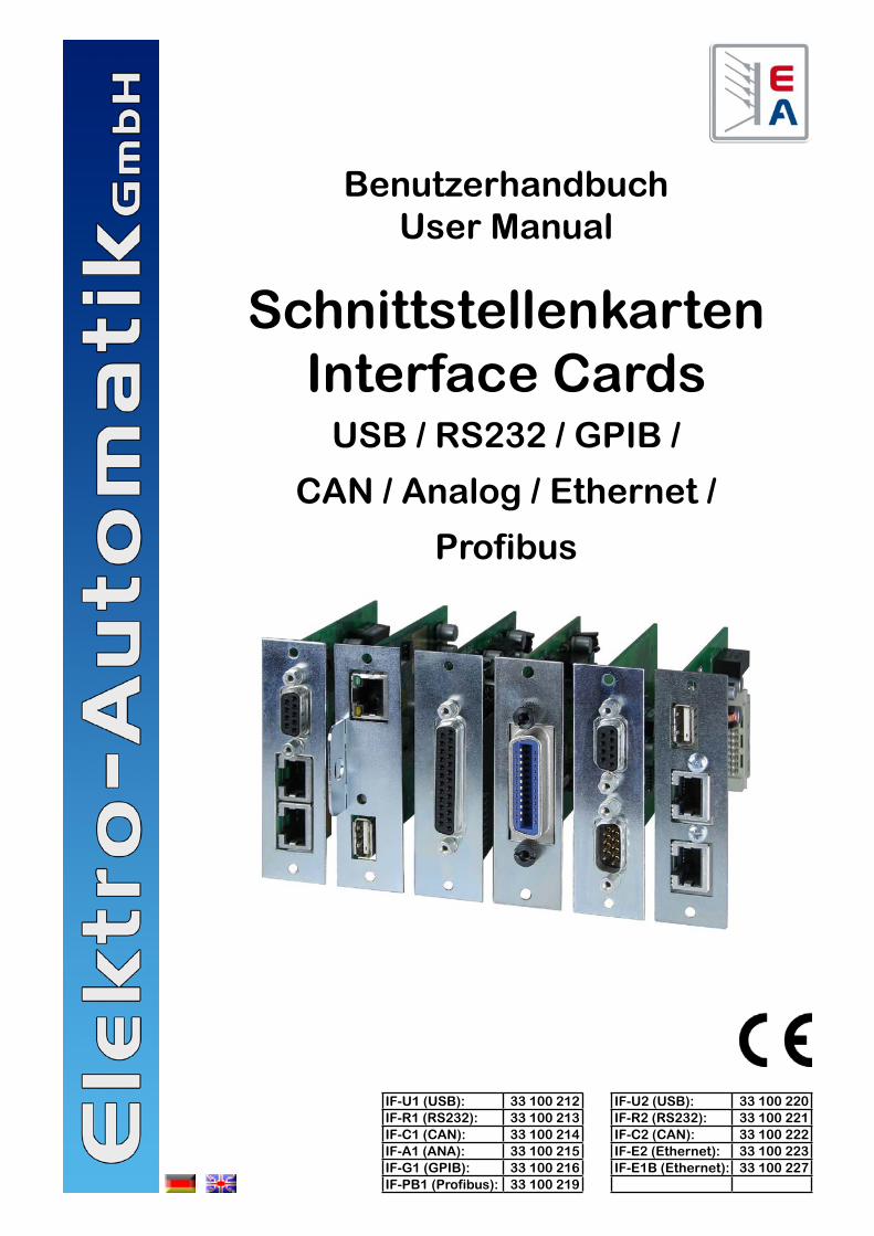
Benutzerhandbuch User Manual Schnittstellenkarten Interface Cards USB / RS232 / GPIB / CAN / Analog / Ethernet / Profibus IF-U1 (USB): 33 100 212 IF-U2 (USB): 33 100 220 IF-R1 (RS232): 33 100 213 IF-R2 (RS232): 33 100 221 IF-C1 (CAN): 33 100 214 IF-C2 (CAN): 33 100 222 IF-A1 (ANA): 33 100 215 IF-E2 (Ethernet): 33 100 223 IF-G1 (GPIB): 33 100 216 IF-E1B (Ethernet): 33 100 227 IF-PB1 (Profibus): 33 100 219
-
Upload
khangminh22 -
Category
Documents
-
view
0 -
download
0
Transcript of Schnittstellenkarten Interface Cards - Conrad Electronic
BenutzerhandbuchUser Manual
Schnittstellenkarten Interface Cards
USB / RS232 / GPIB /
CAN / Analog / Ethernet /
Profibus
IF-U1 (USB): 33 100 212 IF-U2 (USB): 33 100 220IF-R1 (RS232): 33 100 213 IF-R2 (RS232): 33 100 221IF-C1 (CAN): 33 100 214 IF-C2 (CAN): 33 100 222IF-A1 (ANA): 33 100 215 IF-E2 (Ethernet): 33 100 223IF-G1 (GPIB): 33 100 216 IF-E1B (Ethernet): 33 100 227IF-PB1 (Profibus): 33 100 219

2BenutzerhandbuchSchnittstellenkarten IF-XX
DE
Stand: 04.09.2012
Wichtige Hinweise• Bestücken Sie eine oder mehrere Schnittstellenkarten nur
in den dafür vorgesehenen Geräten! Eine Öffnung des Ge-rätes ist nicht erforderlich. Welche Geräte für den Betrieb der Schnittstellenkarten geeignet sind, erfragen Sie bitte bei Ihrem Händler oder Sie lesen es in der Bedienungsan-leitung Ihres Gerätes nach.
• Die Schnittstellenkarten sind nur im ausgeschalteten Zu-stand (Netzschalter aus) zu bestücken!
• Bei der Serie PSI 9000 können zwei Schnittstellenkarten bestückt werden, allerdings ist die Kombination nicht be-liebig. Nähere Information im Abschnitt „3.3 Kombination von Schnittstellenkarten“
• Entfernen Sie niemals die Abdeckbleche an den Karten! • Wenn bei Geräten mit zwei Steckplätzen nur eine Karte
bestückt wird, so montieren Sie ggf. die Abdeckung wieder über den freien Steckplatz!
• Um die Schnittstellenkarten in den dafür vorgesehenen Einschüben zu bestücken, müssen die einschlägigen ESD-Vorschriften beachtet werden.
ImpressumElektro-Automatik GmbH & Co. KGHelmholtzstrasse 31-3341747 ViersenGermanyTelefon: 02162 / 37850Fax: 02162 / 16230Web: www.elektroautomatik.deMail: [email protected]
© Elektro-AutomatikNachdruck, Vervielfältigung oder auszugsweise, zweck-entfremdete Verwendung dieser Bedienungsanleitung sind verboten und können bei Nichtbeachtung rechtliche Schritte nach sich ziehen.
3BenutzerhandbuchSchnittstellenkarten IF-XX
DE
Stand: 04.09.2012
Inhaltsverzeichnis
Seite1. Allgemeines .................................................................................................................................................................... 5
1.1 Einsatzbereich ........................................................................................................................................................... 51.2 Das Gerätekonzept ................................................................................................................................................... 51.3 Garantie/Reparatur ................................................................................................................................................... 51.4 Hinweise zur Beschreibung ....................................................................................................................................... 51.5 Lieferumfang ............................................................................................................................................................. 5
2. Technische Daten ........................................................................................................................................................... 63. Installation ...................................................................................................................................................................... 7
3.1 Sichtprüfung .............................................................................................................................................................. 73.2 Einbau der Schnittstellenkarten ................................................................................................................................ 73.3 Kombination von Schnittstellenkarten ....................................................................................................................... 7
4. RS232-Karte IF-R1 / IF-R2 ............................................................................................................................................. 84.1 RS232-Karte konfigurieren ........................................................................................................................................ 8
5. USB-Karte IF-U1 / IF-U2 ................................................................................................................................................ 85.1 USB-Karte konfigurieren ........................................................................................................................................... 8
6. CAN-Karte IF-C1 / IF-C2 ................................................................................................................................................ 96.1 CAN-Karte konfigurieren ........................................................................................................................................... 96.2 CAN-IDs .................................................................................................................................................................. 10
6.2.1 Bisheriges CAN-ID-System .............................................................................................................................. 106.2.2 Neues CAN-ID-System (ab Oktober 2011) ...................................................................................................... 10
7. Analoge Schnittstelle IF-A1 ...........................................................................................................................................117.1 Pinbelegung der analogen Schnittstelle (25 pol. Sub-D-Buchse) ............................................................................117.2 Allgemeine Hinweise ............................................................................................................................................... 127.3 IF-A1 konfigurieren .................................................................................................................................................. 12
7.3.1 Analoge Eingänge ............................................................................................................................................ 127.3.1.1 PSI 9000 Serie .......................................................................................................................................... 127.3.1.2 PSI 8000 Serien ........................................................................................................................................ 13
7.3.2 Analoge Ausgänge ........................................................................................................................................... 137.3.3 Digitale Eingänge ............................................................................................................................................. 147.3.4 Digitale Ausgänge mit fester Funktionsbelegung ............................................................................................. 157.3.5 Digitale Ausgänge mit freier Funktionsbelegung .............................................................................................. 16
8. GPIB-Karte IF-G1 ......................................................................................................................................................... 178.1 Ansteuerung des Gerätes über GPIB ..................................................................................................................... 178.2 Begriffserläuterung .................................................................................................................................................. 178.3 Firmware-Aktualisierungen ..................................................................................................................................... 178.4 Ausführungs- und Übertragungszeiten ................................................................................................................... 178.5 IF-G1 konfigurieren ................................................................................................................................................. 17
9. Ethernetkarte IF-E1B .................................................................................................................................................... 189.1 Vorbereitung / Hinweise zum Betrieb ...................................................................................................................... 189.2 Ethernetkarte konfigurieren ..................................................................................................................................... 18
9.2.1 Am Gerät .......................................................................................................................................................... 189.2.2 Über das IP-Config-Tool ................................................................................................................................... 199.2.3 Über die Geräte-Webseite ............................................................................................................................... 19
9.3 Mit dem Gerät kommunizieren ................................................................................................................................ 209.3.1 Kommunikation über HTTP .............................................................................................................................. 209.3.2 Kommunikation in LabView .............................................................................................................................. 209.3.3 Kommunikation in anderen Programmiersprachen .......................................................................................... 209.3.4 Kommunikation über die USB-Schnittstelle ..................................................................................................... 20
9.4 Firmwareaktualisierung ........................................................................................................................................... 219.5 Hilfe bei Kommunikationsproblemen ....................................................................................................................... 21
10. Profibuskarte IF-PB1 .................................................................................................................................................... 2210.1 Übertragungsgeschwindigkeit ................................................................................................................................. 2210.2 Profibuskarte konfigurieren ..................................................................................................................................... 2210.3 Verkabelung ............................................................................................................................................................ 2210.4 Busabschluß (Terminierung) ................................................................................................................................... 22
4BenutzerhandbuchSchnittstellenkarten IF-XX
DE
Stand: 04.09.2012
Inhaltsverzeichnis
Seite10.5 Einbindung auf der PC Seite ................................................................................................................................... 2210.6 Weitere Bedienmöglichkeiten .................................................................................................................................. 2210.7 Aktualisierung der Firmware ................................................................................................................................... 2310.8 Kommunikation über den USB-Port ........................................................................................................................ 23
11. Hinweise zu einzelnen Geräteserien ............................................................................................................................ 2411.1 Serien EL 3000 / EL 9000 ....................................................................................................................................... 2411.2 Serien PS 8000 T/ DT / 2U / 3U .............................................................................................................................. 2411.3 Serien PSI 800 R und BCI 800 R ............................................................................................................................ 24
12. Der System Link Mode (nur PSI 9000) ......................................................................................................................... 2512.1 Bedienung des System Link Mode .......................................................................................................................... 25
12.1.1 Anzeige und Bedienung des Masters .............................................................................................................. 2512.1.2 Anzeige der Slaves .......................................................................................................................................... 2512.1.3 Spezielle Alarme, Warnungen und Meldungen ................................................................................................ 26
12.2 Konfiguration des System Link Mode ...................................................................................................................... 2613. Programmierung ........................................................................................................................................................... 2714. Anschlüsse ................................................................................................................................................................... 28
5BenutzerhandbuchSchnittstellenkarten IF-XX
DE
Stand: 04.09.2012
Über die Schnittstellenkarten
1. AllgemeinesDie Schnittstellenkarten IF-Cx (CAN), IF-Rx (RS232), IF-Ux (USB), IF-G1 (GPIB), IF-Ex (Ethernet) und IF-PB1 (Profibus) erlauben eine digitale und die Schnittstellenkarte IF-A1 eine analoge Verbindung zu einer Steuereinheit, wie z.B. einem PC oder einer speicherprogrammierbaren Steuerung (SPS). Mittels der Schnittstellen können die Geräte überwacht und ferngesteuert werden. Dazu gibt es für einige dieser Schnitt-stellenkarten einfache Softwaretools auf der mitgelieferten CD, die die grundlegende Fernsteuerung von Netzgeräten oder elektronischen Lasten zulassen.Die Kartentypen IF-U2, IF-R2, IF-C2 und IF-E2 sind grö-ßenreduzierte Varianten der -1er Typen und finden nur in bestimmten Geräteserien Einsatz. Die 25polige, analoge Schnittstelle IF-A1 (unterstützt von den Serien PSI 9000 und PSI 8000) arbeitet im unmittelbaren Zugriff auf das Netzgerät. Hierdurch können schnelle Ände-rungen der Ausgangswerte unmittelbar beobachtet werden und Sollwerte mit sehr geringer Verzögerung im Rahmen der technischen Daten des angesteuerten Gerätes gesetzt werden. Die digitalen Ein-und Ausgänge sind parametrierbar.Nur Serie PSI 9000: bei Kombination einer IF-C1 Einsteck-karte mit einer RS232- (IF-R1) oder USB-Karte (IF-U1) kann ein sogenannter Gateway von der RS232 oder USB Schnittstelle eines PCs zum CAN-Bus realisiert werden. Somit wird keine extra Hardware für die Anbindung des oder der Geräte an einen CAN-Bus benötigt. Über den Gateway können bis zu 30 Geräte über die RS232/USB-Karte und die CAN-Bus-Vernetzung betrieben werden. Das Gerät, das am PC angeschlossen ist, erledigt die Umsetzung auf CAN und zurück. Die Datenübertragungsgeschwindigkeit ist dann auf die eingestellte reduziert, also max. 57600 Baud.Nur Serie PSI 9000: die Karten IF-R1 und IF-U1 unterstüt-zen die Parallel- und/oder Serienschaltung von mehreren Labornetzteilen zu einem echten Master-Slave-System mit Summenbildung der Meßwerte über den „System Link Mode“. Siehe Handbuch PSI 9000 und Abschnitt „12. Der System Link Mode (nur PSI 9000)“.
1.1 EinsatzbereichDie Einsteckkarte darf nur in dafür vorgesehenen Geräten eingesetzt werden. Im Lieferumfang sind für die digitalen Schnittstellen sind Labview VIs enthalten, die die Integration in ihre LabView-Applikation erleichtern.Die Einbindung in andere Applikationen und Entwicklungs-umgebungen ist möglich, aber auch sehr komplex. Die Telegrammstruktur wird in einem separaten Dokumenten beschrieben. Siehe Ordner „\manuals\interface cards\“ auf der beiliegenden CD oder unsere Webseite (ZIP-Datei mit Handbüchern zu den Schnittstellenkarten).Der effektive Arbeitsbereich der analogen Eingangs- und Ausgangssignale der IF-A1 ist im Bereich von 0..10V an-passbar. Die digitalen Eingangssignale der IF-A1 sind über Kodierstecker zwischen zwei verschiedenen Schaltschwel-len umschaltbar und die Logik im nicht beschalteten Zustand kann vorbestimmt werden. Die digitalen Ausgänge können mit unterschiedlichen Funktionen belegt werden und die Logik invertiert werden.
1.2 Das GerätekonzeptDie Schnittstellenkarten sind steckbar und können in ver-schiedenen Geräten eingesetzt werden. Durch eine Poten-tialtrennung von 2000V (bei Profibuskarte: 1000V) können auch Geräte mit unterschiedlichen Potentialen miteinander verbunden werden.Die RS232-, USB- und CAN-Schnittstellen unterstützen ein einheitliches, objektorientiertes Kommunikationsprofil. Für jede Geräteserie gibt es eine Objektliste. Die Plausibilität der gesendeten Objekte wird von jedem Gerät überprüft. Nicht plausible oder falsche Werte generieren ein Fehler-telegramm. Die digitale Karten IF-G1 und IF-Ex nutzen den international standardisierten Befehlssatz SCPI.Das Profibus-Interface IF-PB1 folgt den typischen Profibus-Spezifikationen.In Abschnitt „13. Programmierung“ ist eine Übersicht über weitere Dokumentation zu finden.
1.3 Garantie/ReparaturAchtung: Die Schnittstellenkarten dürfen nicht vom An-wender repariert werden!Im Garantiefall oder bei einem Defekt kontaktieren Sie Ihren Händler und klären mit diesem ab, welche weiteren Schritte zu tun sind. Auf die Karten wird die gesetzliche Garantie von zwei Jahren gewährt, die allerdings unabhängig von der Garantie des Gerätes ist, in dem die Karten betrieben werden.
1.4 Hinweise zur BeschreibungIn der Beschreibung werden Anzeigeelemente und Be-dienelemente unterschiedlich gekennzeichnet.
Anzeige Alle Anzeigen, die einen Zustand beschreiben, werden mit diesem Symbol gekennzeichnet
Parameter werden hier textlich hervorgehoben
Menüpunkte führen entweder auf die nächst tiefere Menü-Auswahlseite oder auf die un-terste Ebene, der Parameterseite.
… Innerhalb geschweifter Klammern werden mögliche Alternativen oder Bereiche der Einstellung/der Anzeige dargestellt.
1.5 Lieferumfang1 x Steckbare Schnittstellenkarte1 x CD mit Software, Bedienungsanleitungen u.a.1 x Kurzinstallationsanleitung1 x Patchkabel 0,5m 1:1 (nur bei IF-R1 und IF-U1)1 x USB Kabel A-A, 1.8m (nur bei IF-Ux, IF-Ex, IF-PB1)1 x RS232-Kabel 1:1, 3m (nur bei IF-Rx)1 x Programmieradapterkabel für Updates (nur IF-G1)
6BenutzerhandbuchSchnittstellenkarten IF-XX
DE
Stand: 04.09.2012
Über die Schnittstellenkarten
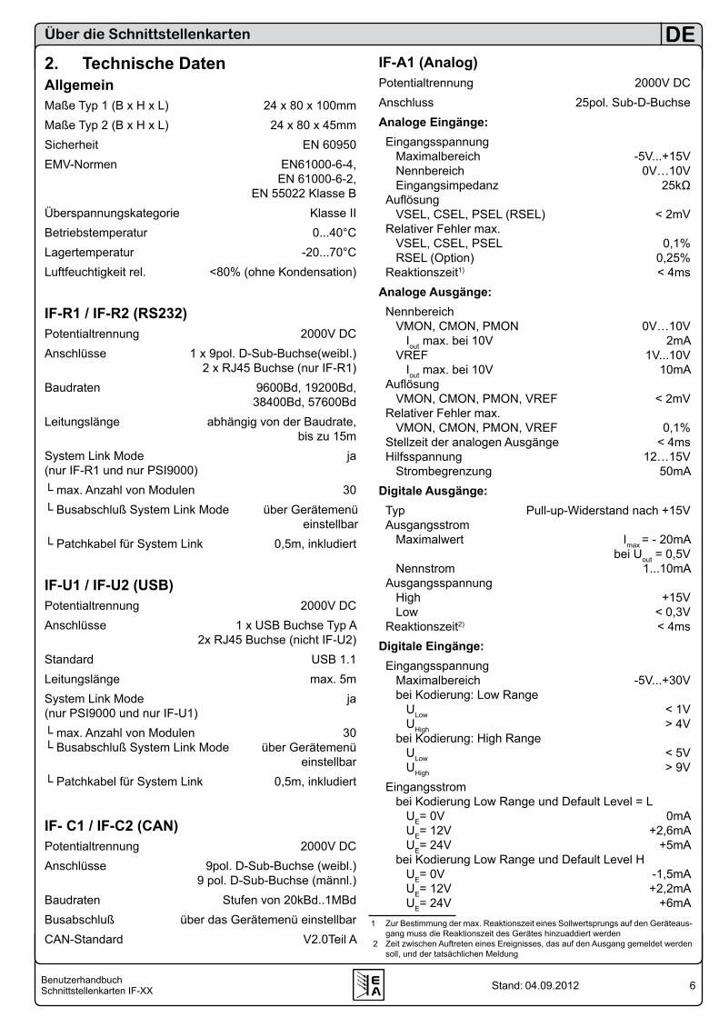
2. Technische DatenAllgemeinMaße Typ 1 (B x H x L) 24 x 80 x 100mmMaße Typ 2 (B x H x L) 24 x 80 x 45mmSicherheit EN 60950EMV-Normen EN61000-6-4, EN 61000-6-2, EN 55022 Klasse BÜberspannungskategorie Klasse IIBetriebstemperatur 0...40°CLagertemperatur -20...70°CLuftfeuchtigkeit rel. <80% (ohne Kondensation)
IF-R1 / IF-R2 (RS232)Potentialtrennung 2000V DCAnschlüsse 1 x 9pol. D-Sub-Buchse(weibl.) 2 x RJ45 Buchse (nur IF-R1)Baudraten 9600Bd, 19200Bd, 38400Bd, 57600BdLeitungslänge abhängig von der Baudrate, bis zu 15mSystem Link Mode ja (nur IF-R1 und nur PSI9000) max. Anzahl von Modulen 30 Busabschluß System Link Mode über Gerätemenü
einstellbar Patchkabel für System Link 0,5m, inkludiert
IF-U1 / IF-U2 (USB)Potentialtrennung 2000V DCAnschlüsse 1 x USB Buchse Typ A 2x RJ45 Buchse (nicht IF-U2)Standard USB 1.1Leitungslänge max. 5mSystem Link Mode ja (nur PSI9000 und nur IF-U1) max. Anzahl von Modulen 30 Busabschluß System Link Mode über Gerätemenü einstellbar Patchkabel für System Link 0,5m, inkludiert
IF- C1 / IF-C2 (CAN)Potentialtrennung 2000V DCAnschlüsse 9pol. D-Sub-Buchse (weibl.) 9 pol. D-Sub-Buchse (männl.)Baudraten Stufen von 20kBd..1MBdBusabschluß über das Gerätemenü einstellbarCAN-Standard V2.0Teil A
IF-A1 (Analog)Potentialtrennung 2000V DCAnschluss 25pol. Sub-D-BuchseAnaloge Eingänge: Eingangsspannung Maximalbereich -5V...+15V Nennbereich 0V…10V Eingangsimpedanz 25kΩ Auflösung VSEL, CSEL, PSEL (RSEL) < 2mV Relativer Fehler max. VSEL, CSEL, PSEL 0,1% RSEL (Option) 0,25% Reaktionszeit1) < 4msAnaloge Ausgänge: Nennbereich VMON, CMON, PMON 0V…10V Iout max. bei 10V 2mA VREF 1V...10V Iout max. bei 10V 10mA Auflösung VMON, CMON, PMON, VREF < 2mV Relativer Fehler max. VMON, CMON, PMON, VREF 0,1% Stellzeit der analogen Ausgänge < 4ms Hilfsspannung 12…15V Strombegrenzung 50mADigitale Ausgänge: Typ Pull-up-Widerstand nach +15V Ausgangsstrom Maximalwert Imax = - 20mA bei Uout = 0,5V Nennstrom 1...10mA Ausgangsspannung High +15V Low < 0,3V Reaktionszeit2) < 4msDigitale Eingänge: Eingangsspannung Maximalbereich -5V...+30V bei Kodierung: Low Range ULow < 1V UHigh > 4V bei Kodierung: High Range ULow < 5V UHigh > 9V Eingangsstrom bei Kodierung Low Range und Default Level = L UE= 0V 0mA UE= 12V +2,6mA UE= 24V +5mA bei Kodierung Low Range und Default Level H UE= 0V -1,5mA UE= 12V +2,2mA UE= 24V +6mA
1 Zur Bestimmung der max. Reaktionszeit eines Sollwertsprungs auf den Geräteaus-gang muss die Reaktionszeit des Gerätes hinzuaddiert werden
2 Zeit zwischen Auftreten eines Ereignisses, das auf den Ausgang gemeldet werden soll, und der tatsächlichen Meldung
7BenutzerhandbuchSchnittstellenkarten IF-XX
DE
Stand: 04.09.2012
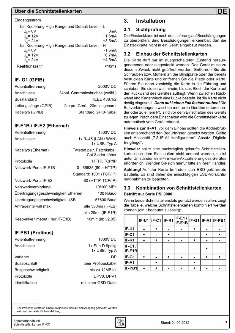
Eingangsstrom bei Kodierung High Range und Default Level = L UE= 0V 0mA UE= 12V +1,6mA UE= 24V +3,5mA bei Kodierung High Range und Default Level = H UE= 0V -1,5mA UE= 12V +0,7mA UE= 24V +4,5mA Reaktionszeit1) <10ms
IF- G1 (GPIB)Potentialtrennung 2000V DCAnschlüsse 24pol. Centronicsbuchse (weibl.)Busstandard IEEE 488.1/2Leitungslänge (GPIB) 2m pro Gerät, 20m insgesamtKabeltyp (GPIB) Standard GPIB-Kabel
IF-E1B / IF-E2 (Ethernet)Potentialtrennung 1500V DCAnschlüsse 1x RJ45 (LAN / WAN) 1x USB, Typ AKabeltyp (Ethernet) Twisted pair, Patchkabel, Cat 3 oder höherProtokolle HTTP, TCP/IPNetzwerk-Ports IF-E1B 0 - 65535 (80 = HTTP) Standard: 1001 (TCP/IP)Netzwerk-Ports IF-E2 80 (HTTP, TCP/IP)Netzwerkverbindung 10/100 MBitÜbertragungsgeschwindigkeit Ethernet 100 kBaudÜbertragungsgeschwindigkeit USB 57600 BaudAnfrageintervall max. alle 300ms (IF-E2) alle 20ms (IF-E1B)Keep-alive timeout ( nur IF-E1B) 10min (ab v2.05)
IF-PB1 (Profibus)Potentialtrennung 1000V DCAnschlüsse 1x Sub-D 9polig 1x USB, Typ AVariante DPBusabschluß über ProfibuskabelBusgeschwindigkeit bis zu 12MBit/sProtokolle DPV0, DPV1Identifikation mit einer GSD-Datei
1 Zeit zwischen Auftreten eines Ereignisses, das auf den Ausgang gemeldet werden soll, und der tatsächlichen Meldung
Über die Schnittstellenkarten
3. Installation3.1 SichtprüfungDie Einsteckkarte ist nach der Lieferung auf Beschädigungen zu überprüfen. Sind Beschädigungen erkennbar, darf die Einsteckkarte nicht in ein Gerät eingebaut werden.
3.2 Einbau der SchnittstellenkartenDie Karte darf nur im ausgeschalteten Zustand heraus-genommen oder eingesteckt werden. Das Gerät muss zu diesem Zweck nicht geöffnet werden. Entfernen Sie die Schrauben bzw. Muttern an der Blindplatte oder der bereits bestückten Karte und entfernen Sie die Platte oder Karte. Führen Sie dann vorsichtig die Karte in die Führung und schieben Sie sie so weit hinein, bis das Blech der Karte auf der Rückwand des Gerätes aufliegt. Wenn zwischen Rück-wand und Kartenblech eine Lücke besteht, ist die Karte nicht richtig eingesetzt. Dann auf keinen Fall festschrauben! Die Busverbindungen zwischen mehreren Geräten untereinan-der oder zu einem PC sind vor dem Einschalten des Geräts zu legen. Nach dem Einschalten wird die Schnittstellenkarte automatisch vom Gerät erkannt.Hinweis zur IF-A1: vor dem Einbau sollten die Kodierbrük-ken entsprechend den Bedürfnissen gesetzt werden. Siehe auch Abschnitt „7.3 IF-A1 konfigurieren“, Absatz „Digitale Eingänge“.Hinweis: sollte eine nachträglich gekaufte Schnittstellen-karte nach dem Einschalten nicht erkannt werden, so ist unter Umständen eine Firmware-Aktualisierung des Gerätes erforderlich. Wenden Sie sich hierfür bitte an Ihren Händler. Achtung! Auf der Karte befinden sich ESD-gefährdete Bauteile. Es sind daher die einschlägigen ESD-Vorsichts-maßnahmen zu beachten.
3.3 Kombination von SchnittstellenkartenBetrifft nur Serie PSI 9000!Wenn beide Schnittstellenslots genutzt werden sollen, zeigt die Tabelle, welche Schnittstellenkarten kombiniert werden können (ein • bedeutet zulässig):
IF-U1 IF-C1 IF-R1 IF-E1 /IF-E1B IF-G1 IF-A1 IF-PB1
IF-U1 - • - - • - -IF-C1 • - • - - • •IF-R1 - • - - • - -IF-E1 /IF-E1B - - - - - • -IF-G1 • - • - - • •IF-A1 - • - - • - -IF-PB1 - • - - • - -
8BenutzerhandbuchSchnittstellenkarten IF-XX
DE
Stand: 04.09.2012
Über die Schnittstellenkarten
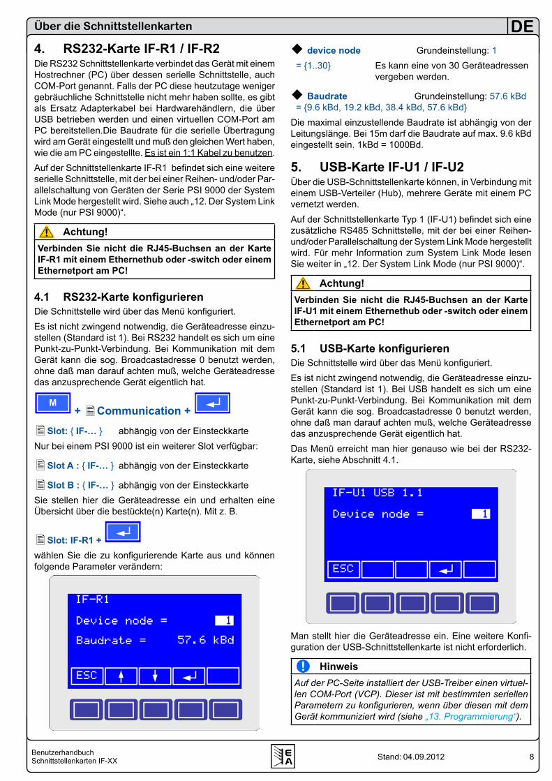
device node Grundeinstellung: 1 = 1..30 Es kann eine von 30 Geräteadressen
vergeben werden.
Baudrate Grundeinstellung: 57.6 kBd = 9.6 kBd, 19.2 kBd, 38.4 kBd, 57.6 kBdDie maximal einzustellende Baudrate ist abhängig von der Leitungslänge. Bei 15m darf die Baudrate auf max. 9.6 kBd eingestellt sein. 1kBd = 1000Bd.
5. USB-Karte IF-U1 / IF-U2Über die USB-Schnittstellenkarte können, in Verbindung mit einem USB-Verteiler (Hub), mehrere Geräte mit einem PC vernetzt werden.Auf der Schnittstellenkarte Typ 1 (IF-U1) befindet sich eine zusätzliche RS485 Schnittstelle, mit der bei einer Reihen- und/oder Parallelschaltung der System Link Mode hergestellt wird. Für mehr Information zum System Link Mode lesen Sie weiter in „12. Der System Link Mode (nur PSI 9000)“.
Achtung!Verbinden Sie nicht die RJ45-Buchsen an der Karte IF-U1 mit einem Ethernethub oder -switch oder einem Ethernetport am PC!
5.1 USB-Karte konfigurierenDie Schnittstelle wird über das Menü konfiguriert.Es ist nicht zwingend notwendig, die Geräteadresse einzu-stellen (Standard ist 1). Bei USB handelt es sich um eine Punkt-zu-Punkt-Verbindung. Bei Kommunikation mit dem Gerät kann die sog. Broadcastadresse 0 benutzt werden, ohne daß man darauf achten muß, welche Geräteadresse das anzusprechende Gerät eigentlich hat.Das Menü erreicht man hier genauso wie bei der RS232-Karte, siehe Abschnitt 4.1.
Man stellt hier die Geräteadresse ein. Eine weitere Konfi-guration der USB-Schnittstellenkarte ist nicht erforderlich.
HinweisAuf der PC-Seite installiert der USB-Treiber einen virtuel-len COM-Port (VCP). Dieser ist mit bestimmten seriellen Parametern zu konfigurieren, wenn über diesen mit dem Gerät kommuniziert wird (siehe „13. Programmierung“).
4. RS232-Karte IF-R1 / IF-R2Die RS232 Schnittstellenkarte verbindet das Gerät mit einem Hostrechner (PC) über dessen serielle Schnittstelle, auch COM-Port genannt. Falls der PC diese heutzutage weniger gebräuchliche Schnittstelle nicht mehr haben sollte, es gibt als Ersatz Adapterkabel bei Hardwarehändlern, die über USB betrieben werden und einen virtuellen COM-Port am PC bereitstellen.Die Baudrate für die serielle Übertragung wird am Gerät eingestellt und muß den gleichen Wert haben, wie die am PC eingestellte. Es ist ein 1:1 Kabel zu benutzen. Auf der Schnittstellenkarte IF-R1 befindet sich eine weitere serielle Schnittstelle, mit der bei einer Reihen- und/oder Par-allelschaltung von Geräten der Serie PSI 9000 der System Link Mode hergestellt wird. Siehe auch „12. Der System Link Mode (nur PSI 9000)“.
Achtung!Verbinden Sie nicht die RJ45-Buchsen an der Karte IF-R1 mit einem Ethernethub oder -switch oder einem Ethernetport am PC!
4.1 RS232-Karte konfigurierenDie Schnittstelle wird über das Menü konfiguriert.Es ist nicht zwingend notwendig, die Geräteadresse einzu-stellen (Standard ist 1). Bei RS232 handelt es sich um eine Punkt-zu-Punkt-Verbindung. Bei Kommunikation mit dem Gerät kann die sog. Broadcastadresse 0 benutzt werden, ohne daß man darauf achten muß, welche Geräteadresse das anzusprechende Gerät eigentlich hat.
M + Communication +
Slot: IF-… abhängig von der EinsteckkarteNur bei einem PSI 9000 ist ein weiterer Slot verfügbar:
Slot A : IF-… abhängig von der Einsteckkarte
Slot B : IF-… abhängig von der EinsteckkarteSie stellen hier die Geräteadresse ein und erhalten eine Übersicht über die bestückte(n) Karte(n). Mit z. B.
Slot: IF-R1 + wählen Sie die zu konfigurierende Karte aus und können folgende Parameter verändern:
9BenutzerhandbuchSchnittstellenkarten IF-XX
DE
Stand: 04.09.2012
Über die Schnittstellenkarten
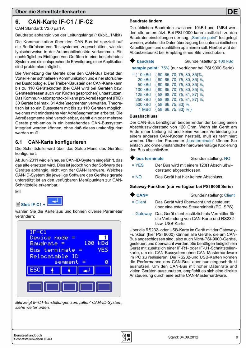
6. CAN-Karte IF-C1 / IF-C2CAN Standard: V2.0 part A Baudrate: abhängig von der Leitungslänge (10kbit...1Mbit)Die Kommunikation über den CAN-Bus ist speziell auf die Bedürfnisse von Testsystemen zugeschnitten, wie sie typischerweise in der Automobilindustrie vorkommen. Ein nachträgliches Einfügen von Geräten in eine bestehendes System und die entsprechende Erweiterung einer Applikation sind problemlos möglich.Die Vernetzung der Geräte über den CAN-Bus bietet den Vorteil einer schnelleren Kommunikation und einer störsiche-ren Bustopologie. Der Treiber-Baustein der CAN-Karte kann bis zu 110 Geräteknoten (bei CAN wird bei Geräten bzw. Geräteadressen auch von Knoten gesprochen) unterstützen. Das Kommunikationsprotokoll kann pro Adreßsegment (RID) 30 Geräte bei max. 31 Adreßsegmenten verwalten. Theore-tisch ist so ein Bussystem mit bis zu 110 Geräten möglich, welches mit mindestens vier Adreßsegmenten arbeitet. Die Adreßsegmente sind verschiebbar, damit ein oder mehrere Geräte problemlos in ein bestehendes CAN-Bussystem integriert werden können, ohne daß dieses umkonfiguriert werden muß.
6.1 CAN-Karte konfigurierenDie Schnittstelle wird über das Setup-Menü des Gerätes konfiguriert.Ab Juni 2011 wird ein neues CAN-ID-System eingeführt, das das alte ersetzen wird. Dies ist jedoch von der Software des Gerätes abhängig, nicht von der CAN-Hardware. Welches CAN-ID-System die jeweilige Software des Gerätes gerade unterstützt ist an den verfügbaren Menüpunkten zur CAN-Schnittstelle erkennbar. Mit
Slot: IF-C1 + wählen Sie die Karte aus und können diverse Parameter verändern:
Bild zeigt IF-C1-Einstellungen zum „alten“ CAN-ID-System, siehe weiter unten.
Baudrate ändernDie üblichen Baudraten zwischen 10kBd und 1MBd wer-den alle unterstützt. Bei PSI 9000 kann zusätzlich zu den Baudrateneinstellungen der sog. „Sample point“ festgelegt werden, welcher die Datenübertragung bei unterschiedlichen Kabellängen- und qualitäten optimieren soll. Hierbei wird der Abtastzeitpunkt bei Empfang eines Bits verschoben.
baudrate Grundeinstellung: 100 kBd sample point: 75% (nur verfügbar bei PSI 9000 Serie) = 10 kBd 60, 65, 70, 75, 80, 85%, 20 kBd 60, 65, 70, 75, 80, 85 %, 50 kBd 60, 65, 70, 75, 80, 85 %, 100 kBd 60, 65, 70, 75, 80, 85 %, 125 kBd 58, 68, 70, 75, 81, 87 %, 250 kBd 58, 68, 70, 75, 81, 87 %, 500 kBd 58, 66, 75, 83 %, 1 MBd 58, 66, 75, 83 % BusabschlussDer CAN-Bus benötigt an beiden Enden der Leitung einen Abschlusswiderstand von 120 Ohm. Wenn ein Gerät am Ende einer Leitung ist und keine weitere Verbindung zu einem anderen CAN-Knoten herstellt, muß es terminiert werden. Über den Parameter „bus terminate“ können Sie einfach und ohne umständliche hardwaremäßige Kodierung den Bus abschließen.
bus terminate Grundeinstellung: NO = YES Der Bus wird mit einem 120Ω Abschlußwi-
derstand abgeschlossen. = NO Das Gerät hat hier keinen Abschluss.
Gateway-Funktion (nur verfügbar bei PSI 9000 Serie)
CAN= Grundeinstellung: Client = Client Das Gerät wird überwacht und gesteuert
über eine externe Steuereinheit (PC, SPS) = Gateway Das Gerät dient zusätzlich als Vermittler für
die Verbindung von CAN-Karte und RS232- bzw. USB-Karte
Über die RS232- oder USB-Karte im Gerät mit der Gateway-Funktion (hier PSI 9000) können alle Geräte, die am CAN-Bus angeschlossen sind, also auch Nicht-PSI-9000-Geräte, gesteuert und überwacht werden. Sie benötigen lediglich ein Gerät mit zusätzlich einer IF-R1- oder IF-U1-Schnittstellen-karte, um ein CAN-Bussystem ohne CAN-Masterhardware im PC zu realisieren. Die RS232-und USB-Karten können die Performance des CAN-Bus’ aber nur eingeschränkt ausnutzen. Um den CAN-Bus mit hoher Datenrate und vielen Geräten auszunutzen, empfiehlt es sich eine direkte Ansteuerung durch eine echte CAN-Masterhardware.

10BenutzerhandbuchSchnittstellenkarten IF-XX
DE
Stand: 04.09.2012
Über die Schnittstellenkarten
6.2 CAN-IDs
6.2.1 Bisheriges CAN-ID-SystemEs ist zwingend erforderlich die Geräteadresse „device node“ einzustellen. Diese ergibt, zusammen mit dem RID, zwei sogenannte Identifier. Das Gerät kann nur so eindeutig im System identifiziert werden. Über diese Identifier wird das Gerät angesprochen. Jedes Gerät muß eine andere Geräte-adresse bekommen, wenn mehrere gleichzeitig vom einem Steuergerät gesteuert werden.
Adressbereiche verschiebenFalls in ein bestehendes CAN-Bus-System ein oder mehrere Geräte mit einer CAN-Schnittstellenkarte integriert werden sollen, so kann über das „relocatable identifier segment“ (kurz: RID) der Adressbereich der neuen Geräte so ver-schoben werden, dass die CAN-Adressen (auch identifier genannt) der neuen Geräte mit schon definierten Adressen nicht kollidieren.Der CAN-Bus nach dem Standard V2.0a definiert einen 11 Bit langen Identifier, wodurch sich 2032 zulässige Adressen für Geräte ergeben. Diese 2032 Identifier werden durch das hier verwendete System in 32 Adreßsegmente á 64 Adressen (je eine für Schreiben und Lesen) unterteilt. Der Beginn dieser Adreßsegmente wird mit dem RID festgelegt.
relocatable ID Grundeinstellung: 0 segment = 0..31 Verschiebt das AdreßsegmentInnerhalb jedes Adreßsegments gibt es 62 frei verteilbare Adressen, wobei hier die bis zu 30 Geräte den unteren Be-reich belegen und bei 2 physikalischen Adressen (identifier) pro Gerät (je ein Identifier für Empfang und Senden von Da-ten am CAN-Knoten) somit die Adressen 2...61 belegen. Die Adressen 0 und 1 jedes Bereiches sind fest für Broadcast-Nachrichten an Geräte in diesem Bereich reserviert. Somit ergeben sich 64 Broadcast-Adressen. Grundsätzlich sind für Broadcast-Nachrichten die Adressen festgelegt:[RID*64 + 0] und [RID*64 + 1].Beispiel: RID ist auf 5 gesetzt (siehe Setup-Menü der jewei-ligen Geräte). Es soll ein Broadcast an die Geräte dieses Adreßsegments gehen. Der Identifier, der sich dadurch ergibt muß dann 5*64=320=0x140 bzw. 0x141 (für Lesen) sein.Für Singlecast-Nachrichten belegt jedes Gerät mir seinem „device node“ zwei weitere Adressen:[RID*64 + device node * 2] und[RID*64 + device node * 2 + 1]Beispiel: der RID wurde auf 13, die Geräteadresse (device node) auf 12 gesetzt. Zum Ansteuern des Zielgerätes muß der Identifier 13*64 + 12*2 = 856 (0x358) benutzt werden. Der Identifier 857 (0x359) wird dann für Anfragen benutzt.
6.2.2 Neues CAN-ID-System (ab Oktober 2011)Das neue CAN-ID-System ist zunächst für die Serien PS 8000 und EL3000/EL9000verfügbar. Die Serie PSI 8000 wird später folgen. Andere Serie auf Anfrage.Hier ist es zumindest erforderlich, die Basis-ID des Gerätes einzustellen. Diese bestimmt dann die drei normalen CAN-IDs des Gerätes. Sofern die sog. Broadcast-ID nicht mit einer CAN-ID kollidiert, kann sie unbeachtet gelassen werden.Für die Einstellungen bei einem Gerät der Serie PS 8000 lesen Sie bitte im Gerätehandbuch nach.Für PSI 8000 sieht das Setup dann so aus:
Base ID Grundeinstellung: 0x000Stellt die Basis-CAN-ID als Hexadezimalwert in 4er-Schritten ein. Das Gerät bekommt dann drei normale CAN-IDs: Base ID, Base ID +1 und Base-ID + 2. Dieses System ist kom-patibel zu Vector-Software wie CANoe oder CANalyzer. Passende Datenbasen im *.dbc Format sind verfügbar. Diese sind entweder auf der der Schnittstellenkarte beilie-genden CD enthalten oder auf Anfrage erhältlich. Für jedes Modell einer Serie ist eine separate Datenbasis erforderlich. Demo-Konfigurationen für CANalyzer oder CANoe können auf Anfrage erstellt werden. Diese bieten eine einfache Te-stoberfläche für die wichtigsten Funktionen.
Broadcast ID Grundeinstellung: 0x7FFStellt die sog. Broadcast-ID des Gerätes als Hexdezimalwert ein. Diese ID und darf nicht mit einer der normalen CAN-IDs kollidieren. Sinn dieser zusätzlichen ID ist es, diese bei mehreren möglichst identischen Geräten, die an einem Bus verbunden sind, gleich einzustellen, damit diese alle auf einen an diese ID gesendeten Befehl reagieren und somit gleichzeitig einen bestimmten Stromsollwert setzen oder z. B. den Ausgang einschalten können. Diese ID kann nur zum Senden von Werten und Zuständen verwendet werden, Abfrage per Broadcast ist nicht möglich.Die weiteren Einstellungen siehe 6.2.1.
11BenutzerhandbuchSchnittstellenkarten IF-XX
DE
Stand: 04.09.2012
Über die Schnittstellenkarten
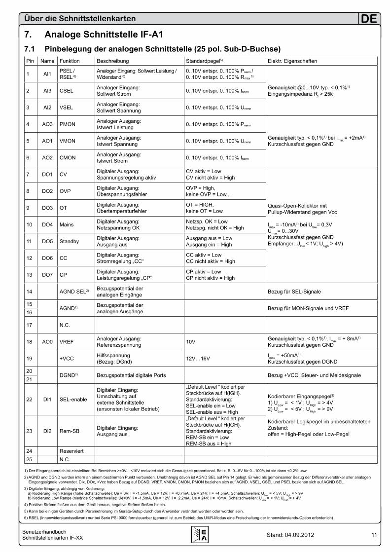
7. Analoge Schnittstelle IF-A17.1 Pinbelegung der analogen Schnittstelle (25 pol. Sub-D-Buchse)Pin Name Funktion Beschreibung Standardpegel5) Elektr. Eigenschaften
1 AI1 PSEL /RSEL 6)
Analoger Eingang: Sollwert Leistung / Widerstand 6)
0..10V entspr. 0..100% Pnenn / 0..10V entspr. 0..100% Rmax
6)
Genauigkeit @0...10V typ. < 0,1%1)
Eingangsimpedanz Ri > 25k2 AI3 CSEL Analoger Eingang: Sollwert Strom 0..10V entspr. 0..100% Inenn
3 AI2 VSEL Analoger Eingang: Sollwert Spannung 0..10V entspr. 0..100% Unenn
4 AO3 PMON Analoger Ausgang: Istwert Leistung 0..10V entspr. 0..100% Pnenn
Genauigkeit typ. < 0,1%1) bei Imax = +2mA4)
Kurzschlussfest gegen GND5 AO1 VMON Analoger Ausgang: Istwert Spannung 0..10V entspr. 0..100% Unenn
6 AO2 CMON Analoger Ausgang: Istwert Strom 0..10V entspr. 0..100% Inenn
7 DO1 CV Digitaler Ausgang: Spannungsregelung aktiv
CV aktiv = Low CV nicht aktiv = High
Quasi-Open-Kollektor mit Pullup-Widerstand gegen Vcc
Imax = -10mA4) bei Ulow= 0,3VUmax= 0...30VKurzschlussfest gegen GND Empfänger: Ulow < 1V; Uhigh > 4V)
8 DO2 OVP Digitaler Ausgang: Überspannungsfehler
OVP = High, keine OVP = Low ,
9 DO3 OT Digitaler Ausgang: Übertemperaturfehler
OT = HIGH, keine OT = Low
10 DO4 Mains Digitaler Ausgang: Netzspannung OK
Netzsp. OK = Low Netzspg. nicht OK = High
11 DO5 Standby Digitaler Ausgang: Ausgang aus
Ausgang aus = LowAusgang ein = High
12 DO6 CC Digitaler Ausgang: Stromregelung „CC“
CC aktiv = Low CC nicht aktiv = High
13 DO7 CP Digitaler Ausgang: Leistungsregelung „CP“
CP aktiv = Low CP nicht aktiv = High
14 AGND SEL2) Bezugspotential der analogen Eingänge Bezug für SEL-Signale
15AGND2) Bezugspotential der
analogen Ausgänge Bezug für MON-Signale und VREF16
17 N.C.
18 AO0 VREF Analoger Ausgang: Referenzspannung 10V Genauigkeit typ. < 0,1%1), Imax = + 8mA4)
Kurzschlussfest gegen GND
19 +VCC Hilfsspannung (Bezug: DGnd) 12V…16V Imax = +50mA4)
Kurzschlussfest gegen DGND
20DGND2) Bezugspotential digitale Ports Bezug +VCC, Steuer- und Meldesignale
21
22 DI1 SEL-enable
Digitaler Eingang:Umschaltung auf externe Schnittstelle (ansonsten lokaler Betrieb)
„Default Level “ kodiert per Steckbrücke auf H(IGH).Standardaktivierung:SEL-enable ein = LowSEL-enable aus = High
Kodierbarer Eingangspegel3)
1) ULow = < 1V ; UHigh = > 4V2) ULow = < 5V ; UHigh = > 9V
Kodierbarer Logikpegel im unbeschalteteten Zustand:offen = High-Pegel oder Low-Pegel23 DI2 Rem-SB Digitaler Eingang:
Ausgang aus
„Default Level “ kodiert per Steckbrücke auf H(IGH).Standardaktivierung:REM-SB ein = LowREM-SB aus = High
24 Reserviert25 N.C.
1) Der Eingangsbereich ist einstellbar. Bei Bereichen >=0V....<10V reduziert sich die Genauigkeit proportional. Bei z. B. 0...5V für 0...100% ist sie dann <0,2% usw.
2) AGND und DGND werden intern an einem bestimmten Punkt verbunden. Unabhängig davon ist AGND SEL auf Pin 14 gelegt. Er wird als gemeinsamer Bezug der Differenzverstärker aller analogen Eingangssignale verwendet. DIx, DOx, +Vcc haben Bezug auf DGND. VREF, VMON, CMON, PMON beziehen sich auf AGND. VSEL, CSEL und PSEL beziehen sich auf AGND SEL.
3) Digitaler Eingang, abhängig von Kodierung: a) Kodierung High Range (hohe Schaltschwelle): Ue = 0V; I = -1,5mA, Ue = 12V; I = +0,7mA; Ue = 24V; I = +4,5mA, Schaltschwellen: ULow = < 5V; UHigh = > 9V b) Kodierung Low Range (niedrige Schaltschwelle): Ue=0V; I = -1,5mA, Ue = 12V; I = 2,2mA, Ue = 24V; I = +6mA, Schaltschwellen: ULow = < 1V; UHigh = > 4V
4) Positive Ströme fließen aus dem Gerät heraus, negative Ströme fließen hinein.
5) Kann bei einigen Geräten durch Parametrierung im Geräte-Setup durch den Anwender verändert werden oder worden sein.
6) RSEL (Innenwiderstandssollwert) nur bei Serie PSI 9000 fernsteuerbar (generell ist zum Betrieb des U/I/R-Modus eine Freischaltung der Innenwiderstands-Option erforderlich)
12BenutzerhandbuchSchnittstellenkarten IF-XX
DE
Stand: 04.09.2012
Über die Schnittstellenkarten
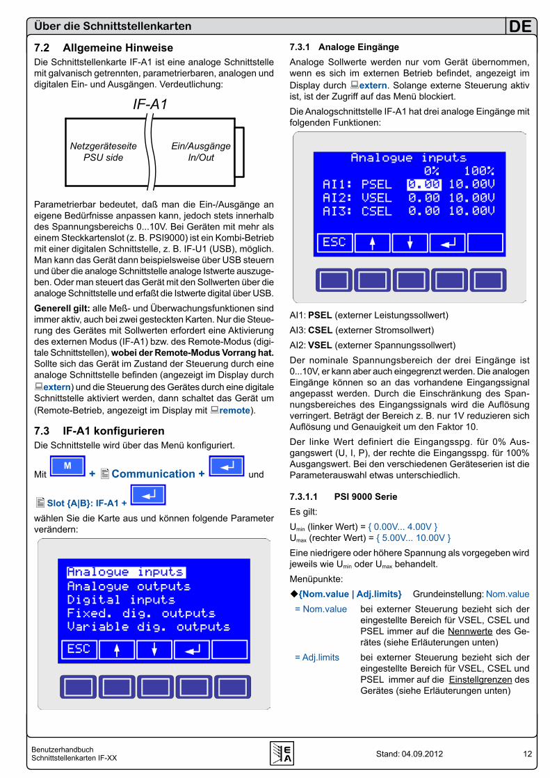
7.2 Allgemeine HinweiseDie Schnittstellenkarte IF-A1 ist eine analoge Schnittstelle mit galvanisch getrennten, parametrierbaren, analogen und digitalen Ein- und Ausgängen. Verdeutlichung:
Parametrierbar bedeutet, daß man die Ein-/Ausgänge an eigene Bedürfnisse anpassen kann, jedoch stets innerhalb des Spannungsbereichs 0...10V. Bei Geräten mit mehr als einem Steckkartenslot (z. B. PSI9000) ist ein Kombi-Betrieb mit einer digitalen Schnittstelle, z. B. IF-U1 (USB), möglich. Man kann das Gerät dann beispielsweise über USB steuern und über die analoge Schnittstelle analoge Istwerte auszuge-ben. Oder man steuert das Gerät mit den Sollwerten über die analoge Schnittstelle und erfaßt die Istwerte digital über USB. Generell gilt: alle Meß- und Überwachungsfunktionen sind immer aktiv, auch bei zwei gesteckten Karten. Nur die Steue-rung des Gerätes mit Sollwerten erfordert eine Aktivierung des externen Modus (IF-A1) bzw. des Remote-Modus (digi-tale Schnittstellen), wobei der Remote-Modus Vorrang hat. Sollte sich das Gerät im Zustand der Steuerung durch eine analoge Schnittstelle befinden (angezeigt im Display durch extern) und die Steuerung des Gerätes durch eine digitale Schnittstelle aktiviert werden, dann schaltet das Gerät um (Remote-Betrieb, angezeigt im Display mit remote).
7.3 IF-A1 konfigurierenDie Schnittstelle wird über das Menü konfiguriert.
Mit M
+ Communication + und
Slot A|B: IF-A1 + wählen Sie die Karte aus und können folgende Parameter verändern:
7.3.1 Analoge EingängeAnaloge Sollwerte werden nur vom Gerät übernommen, wenn es sich im externen Betrieb befindet, angezeigt im Display durch extern. Solange externe Steuerung aktiv ist, ist der Zugriff auf das Menü blockiert.Die Analogschnittstelle IF-A1 hat drei analoge Eingänge mit folgenden Funktionen:
AI1: PSEL (externer Leistungssollwert) AI3: CSEL (externer Stromsollwert)AI2: VSEL (externer Spannungssollwert)Der nominale Spannungsbereich der drei Eingänge ist 0...10V, er kann aber auch eingegrenzt werden. Die analogen Eingänge können so an das vorhandene Eingangssignal angepasst werden. Durch die Einschränkung des Span-nungsbereiches des Eingangssignals wird die Auflösung verringert. Beträgt der Bereich z. B. nur 1V reduzieren sich Auflösung und Genauigkeit um den Faktor 10. Der linke Wert definiert die Eingangsspg. für 0% Aus-gangswert (U, I, P), der rechte die Eingangsspg. für 100% Ausgangswert. Bei den verschiedenen Geräteserien ist die Parameterauswahl etwas unterschiedlich.
7.3.1.1 PSI 9000 SerieEs gilt:Umin (linker Wert) = 0.00V... 4.00V Umax (rechter Wert) = 5.00V... 10.00V Eine niedrigere oder höhere Spannung als vorgegeben wird jeweils wie Umin oder Umax behandelt.Menüpunkte:Nom.value | Adj.limits Grundeinstellung: Nom.value
= Nom.value bei externer Steuerung bezieht sich der eingestellte Bereich für VSEL, CSEL und PSEL immer auf die Nennwerte des Ge-rätes (siehe Erläuterungen unten)
= Adj.limits bei externer Steuerung bezieht sich der eingestellte Bereich für VSEL, CSEL und PSEL immer auf die Einstellgrenzen des Gerätes (siehe Erläuterungen unten)
IF-A1
NetzgeräteseitePSU side
Ein/AusgängeIn/Out
13BenutzerhandbuchSchnittstellenkarten IF-XX
DE
Stand: 04.09.2012
AI1 Grundeinstellung: Psel 0.00 10.00V = PSEL|RSEL|- Pin zu gewiesen für externen Leist- ungs- oder Widerstandssollwert oder unbenutztRsel ist nur verfügbar, wenn der U/I/R-Betrieb freigeschaltet wurde. Falls AI1 auf „-“ gesetzt wurde, ist eine Vorgabe des Leistungssollwertes nicht erforderlich. Der Leistungssollwert wird dann auf dem zuletzt eingestellten Wert gehalten.AI2 Grundeinstellung: 0.00 10.00V = VSEL externer SpannungssollwertAI3 Grundeinstellung: 0.00 10.00V = CSEL externer Stromsollwert
Erläuterung zu Nom.valueBei dieser Einstellung wird der gewählte Eingangsspan-nungsbereich für die Sollwerteingänge immer auf den jewei-ligen Nennwert (U, I oder P) des Gerätes bezogen. Beispiel: Sie haben ein PSI 9080-100. Das hat die Nennwerte 80V, 100A und 3000W. Wenn Sie nun für den Eingang VSEL einen Bereich von 0...10V für 0...100% einstellen, dann wird das Gerät am Ausgang 100% oder 80V ausgeben, wenn in VSEL 10V eingespeist werden. Ist der Bereich z. B. auf 3...7V eingestellt, gibt das Gerät die 100% bzw. 80V bereits bei 7V Steuerspannung an VSEL heraus. Bei den anderen Sollwerten verhält sich das genauso.
HinweisDie maximale Ausgangsspannung, -strom und -leistung können zusätzlich durch Grenzwerte eingeschränkt sein. Siehe Gerätehandbuch, Menü „Profile -> General settings -> Adjust limits“.
Erläuterung zu Adj.limitsBei dieser Einstellung wird der gewählte Eingangsspan-nungsbereich für die Sollwerteingänge immer auf den jewei-ligen Nennwert (U, I oder P) des Gerätes bezogen. Beispiel: Sie haben ein PSI 9080-100. Das hat die Nennwerte 80V, 100A und 3000W. Der Ausgangsstrom ist jedoch im Menü „Profile->General settings->Adjust Limits“ auf max. 50A Einstellgrenze begrenzt worden. Wenn man dann alle drei Sollwerteingänge auf 0...5V einstellt, dann würde bei Vorgabe von 5V das Gerät 100% Spannung, also 80V, 50% Strom, also 50A, und 100% Leistung, also 3000W herausge-ben. Bei den anderen Sollwerten verhält sich das genauso.
7.3.1.2 PSI 8000 Serien
HinweisBei den Modellen T, DT, 2U oder 3U der Serie PSI 8000 ist eine eingebaute Analogschnittstelle vorhanden, für die im Menü des Gerätes ein Menüpunkt „Analogue interface“ vorhanden ist. Dieser ist nicht für die Schnittstellenkarte IF-A1, die hier beschrieben wird!
Es gilt:Umin (linker Wert) = 0.00V...4.00VUmax (rechter Wert) = 5.00V...10.00V
Über die Schnittstellenkarten
Der eingestellte Bereich, z. B. 2.00V...8.00V, entspricht immer 0...100% Sollwert. Eine niedrigere oder höhere Span-nung wird jeweils wie Umin oder Umax behandelt. Siehe auch oben „Erläuterung zu Nom.value“, da hier fix das Verhalten des Gerätes wie bei Einstellung „Nom.value“ eines PSI 9000 implementiert ist. Menüpunkte:AI1 Grundeinstellung: 0.00 10.00V = PSEL externer LeistungssollwertAI2 Grundeinstellung: 0.00 10.00V = VSEL externer SpannungssollwertAI3 Grundeinstellung: 0.00 10.00V = CSEL externer Stromsollwert
HinweisDie maximale Ausgangsspannung, -strom und -leistung können zusätzlich durch Grenzwerte eingeschränkt sein. Siehe Gerätehandbuch, Menü „Profile -> General settings -> Adjust limits“.
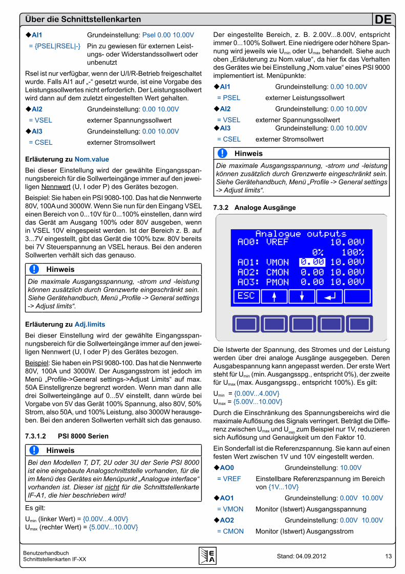
7.3.2 Analoge Ausgänge
Die Istwerte der Spannung, des Stromes und der Leistung werden über drei analoge Ausgänge ausgegeben. Deren Ausgabespannung kann angepasst werden. Der erste Wert steht für Umin (min. Ausgangsspg., entspricht 0%), der zweite für Umax (max. Ausgangsspg., entspricht 100%). Es gilt:Umin = 0.00V...4.00VUmax = 5.00V...10.00VDurch die Einschränkung des Spannungsbereichs wird die maximale Auflösung des Signals verringert. Beträgt die Diffe-renz zwischen Umax und Umin zum Beispiel nur 1V, reduzieren sich Auflösung und Genauigkeit um den Faktor 10.Ein Sonderfall ist die Referenzspannung. Sie kann auf einen festen Wert zwischen 1V und 10V eingestellt werden.AO0 Grundeinstellung: 10.00V = VREF Einstellbare Referenzspannung im Bereich
von 1V...10VAO1 Grundeinstellung: 0.00V 10.00V = VMON Monitor (Istwert) AusgangsspannungAO2 Grundeinstellung: 0.00V 10.00V = CMON Monitor (Istwert) Ausgangsstrom
14BenutzerhandbuchSchnittstellenkarten IF-XX
DE
Stand: 04.09.2012
AO3 Grundeinstellung: 0.00V 10.00V = PMON Monitor (Istwert) AusgangsleistungZusätzlich gibt es bei Geräten der Serie PSI 9000 noch folgende Einstellung:Nom.value | Adj.limits Grundeinstellung: Nom.value = Nom.value bei externer Steuerung bezieht sich der eingestellte Bereich für Vmon, Cmon und Pmon immer auf die Nennwerte des Gerätes (siehe Absatz „Erläuterung zu Nom.value“ oben) = Adj.limits bei externer Steuerung bezieht sich der eingestellte Bereich für Vmon, Cmon und Pmon immer auf die Einstellgrenzen des Gerätes (siehe Absatz „Erläuterung zu Adj.limits“ oben)Das Verhalten der Istwertausgänge ist vom Spannungsbe-reich her das gleiche wie bei den Sollwerteingängen.
HinweisEs wird empfohlen, bei PSI 9000 Geräten die Einstellung „Nom.value / Adj.limits“ bei den analogen Aus- und Ein-gängen gleichzuhalten.
HinweisDie maximale Ausgangsspannung, -strom und -leistung können zusätzlich durch Grenzwerte eingeschränkt sein. Siehe Gerätehandbuch, Menü „Profile -> General settings -> Adjust limits“.
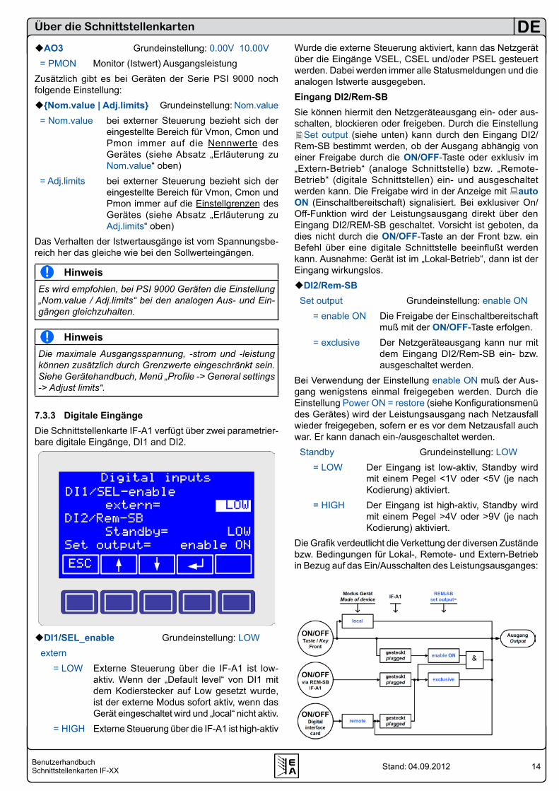
7.3.3 Digitale EingängeDie Schnittstellenkarte IF-A1 verfügt über zwei parametrier-bare digitale Eingänge, DI1 and DI2.
DI1/SEL_enable Grundeinstellung: LOW extern = LOW Externe Steuerung über die IF-A1 ist low-
aktiv. Wenn der „Default level“ von DI1 mit dem Kodierstecker auf Low gesetzt wurde, ist der externe Modus sofort aktiv, wenn das Gerät eingeschaltet wird und „local“ nicht aktiv.
= HIGH Externe Steuerung über die IF-A1 ist high-aktiv
Über die Schnittstellenkarten
Wurde die externe Steuerung aktiviert, kann das Netzgerät über die Eingänge VSEL, CSEL und/oder PSEL gesteuert werden. Dabei werden immer alle Statusmeldungen und die analogen Istwerte ausgegeben.Eingang DI2/Rem-SBSie können hiermit den Netzgeräteausgang ein- oder aus-schalten, blockieren oder freigeben. Durch die Einstellung Set output (siehe unten) kann durch den Eingang DI2/Rem-SB bestimmt werden, ob der Ausgang abhängig von einer Freigabe durch die ON/OFF-Taste oder exklusiv im „Extern-Betrieb“ (analoge Schnittstelle) bzw. „Remote-Betrieb“ (digitale Schnittstellen) ein- und ausgeschaltet werden kann. Die Freigabe wird in der Anzeige mit auto ON (Einschaltbereitschaft) signalisiert. Bei exklusiver On/Off-Funktion wird der Leistungsausgang direkt über den Eingang DI2/REM-SB geschaltet. Vorsicht ist geboten, da dies nicht durch die ON/OFF-Taste an der Front bzw. ein Befehl über eine digitale Schnittstelle beeinflußt werden kann. Ausnahme: Gerät ist im „Lokal-Betrieb“, dann ist der Eingang wirkungslos.DI2/Rem-SB
Set output Grundeinstellung: enable ON = enable ON Die Freigabe der Einschaltbereitschaft
muß mit der ON/OFF-Taste erfolgen. = exclusive Der Netzgeräteausgang kann nur mit
dem Eingang DI2/Rem-SB ein- bzw. ausgeschaltet werden.
Bei Verwendung der Einstellung enable ON muß der Aus-gang wenigstens einmal freigegeben werden. Durch die Einstellung Power ON = restore (siehe Konfigurationsmenü des Gerätes) wird der Leistungsausgang nach Netzausfall wieder freigegeben, sofern er es vor dem Netzausfall auch war. Er kann danach ein-/ausgeschaltet werden.
Standby Grundeinstellung: LOW = LOW Der Eingang ist low-aktiv, Standby wird
mit einem Pegel <1V oder <5V (je nach Kodierung) aktiviert.
= HIGH Der Eingang ist high-aktiv, Standby wird mit einem Pegel >4V oder >9V (je nach Kodierung) aktiviert.
Die Grafik verdeutlicht die Verkettung der diversen Zustände bzw. Bedingungen für Lokal-, Remote- und Extern-Betrieb in Bezug auf das Ein/Ausschalten des Leistungsausganges:
15BenutzerhandbuchSchnittstellenkarten IF-XX
DE
Stand: 04.09.2012
Über die Schnittstellenkarten
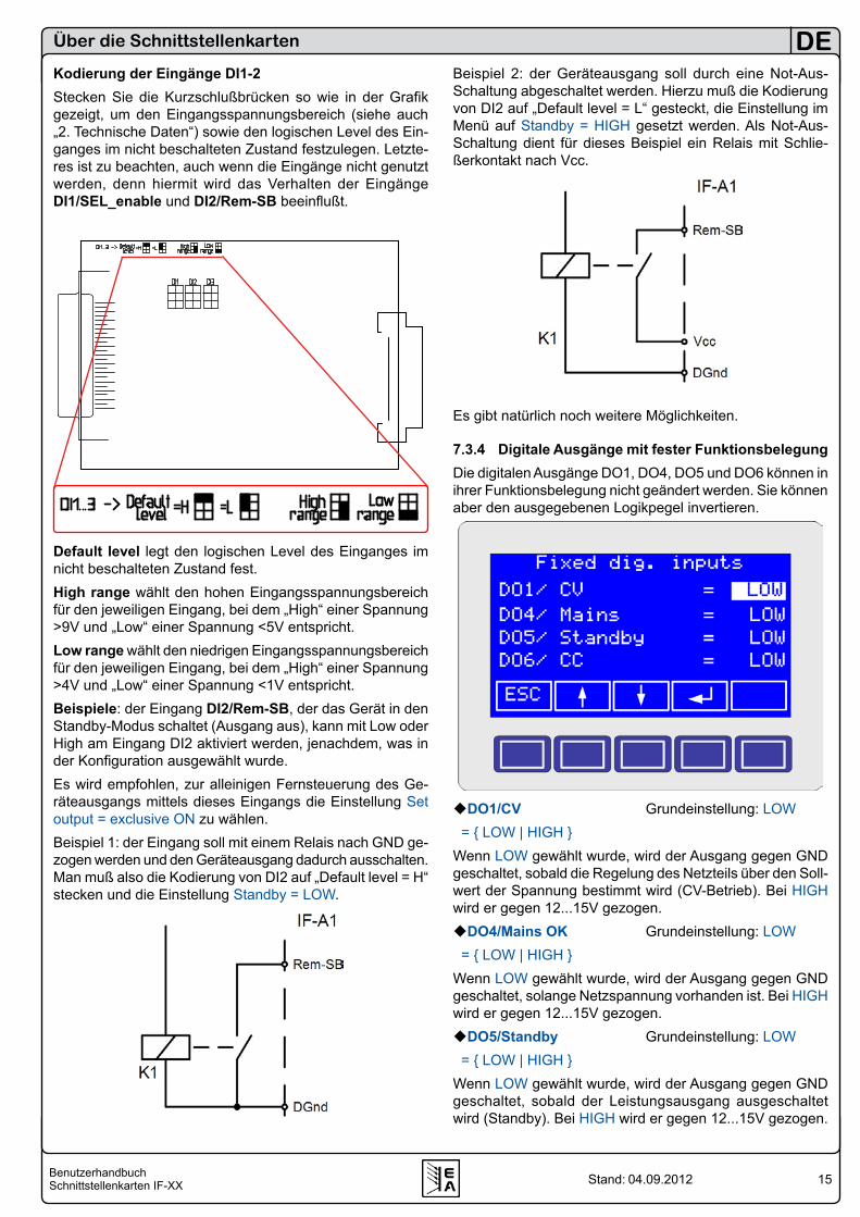
Kodierung der Eingänge DI1-2Stecken Sie die Kurzschlußbrücken so wie in der Grafik gezeigt, um den Eingangsspannungsbereich (siehe auch „2. Technische Daten“) sowie den logischen Level des Ein-ganges im nicht beschalteten Zustand festzulegen. Letzte-res ist zu beachten, auch wenn die Eingänge nicht genutzt werden, denn hiermit wird das Verhalten der Eingänge DI1/SEL_enable und DI2/Rem-SB beeinflußt.
Default level legt den logischen Level des Einganges im nicht beschalteten Zustand fest.High range wählt den hohen Eingangsspannungsbereich für den jeweiligen Eingang, bei dem „High“ einer Spannung >9V und „Low“ einer Spannung <5V entspricht.Low range wählt den niedrigen Eingangsspannungsbereich für den jeweiligen Eingang, bei dem „High“ einer Spannung >4V und „Low“ einer Spannung <1V entspricht.Beispiele: der Eingang DI2/Rem-SB, der das Gerät in den Standby-Modus schaltet (Ausgang aus), kann mit Low oder High am Eingang DI2 aktiviert werden, jenachdem, was in der Konfiguration ausgewählt wurde. Es wird empfohlen, zur alleinigen Fernsteuerung des Ge-räteausgangs mittels dieses Eingangs die Einstellung Set output = exclusive ON zu wählen.Beispiel 1: der Eingang soll mit einem Relais nach GND ge-zogen werden und den Geräteausgang dadurch ausschalten. Man muß also die Kodierung von DI2 auf „Default level = H“ stecken und die Einstellung Standby = LOW.
Beispiel 2: der Geräteausgang soll durch eine Not-Aus-Schaltung abgeschaltet werden. Hierzu muß die Kodierung von DI2 auf „Default level = L“ gesteckt, die Einstellung im Menü auf Standby = HIGH gesetzt werden. Als Not-Aus-Schaltung dient für dieses Beispiel ein Relais mit Schlie-ßerkontakt nach Vcc.
Es gibt natürlich noch weitere Möglichkeiten.
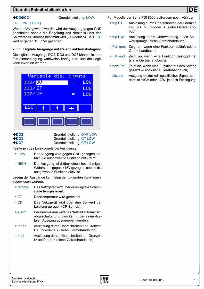
7.3.4 Digitale Ausgänge mit fester FunktionsbelegungDie digitalen Ausgänge DO1, DO4, DO5 und DO6 können in ihrer Funktionsbelegung nicht geändert werden. Sie können aber den ausgegebenen Logikpegel invertieren.
DO1/CV Grundeinstellung: LOW = LOW | HIGH Wenn LOW gewählt wurde, wird der Ausgang gegen GND geschaltet, sobald die Regelung des Netzteils über den Soll-wert der Spannung bestimmt wird (CV-Betrieb). Bei HIGH wird er gegen 12...15V gezogen.DO4/Mains OK Grundeinstellung: LOW = LOW | HIGH Wenn LOW gewählt wurde, wird der Ausgang gegen GND geschaltet, solange Netzspannung vorhanden ist. Bei HIGH wird er gegen 12...15V gezogen. DO5/Standby Grundeinstellung: LOW = LOW | HIGH Wenn LOW gewählt wurde, wird der Ausgang gegen GND geschaltet, sobald der Leistungsausgang ausgeschaltet wird (Standby). Bei HIGH wird er gegen 12...15V gezogen.
16BenutzerhandbuchSchnittstellenkarten IF-XX
DE
Stand: 04.09.2012
Über die Schnittstellenkarten
DO6/CC Grundeinstellung: LOW = LOW | HIGH Wenn LOW gewählt wurde, wird der Ausgang gegen GND geschaltet, sobald die Regelung des Netzteils über den Sollwert des Stromes bestimmt wird (CC-Betrieb). Bei HIGH wird er gegen 12...15V gezogen.
7.3.5 Digitale Ausgänge mit freier FunktionsbelegungDie digitalen Ausgänge DO2, DO3 und DO7 können in ihrer Funktionsbelegung wahlweise konfiguriert und die Logik kann invertiert werden.
DO2 Grundeinstellung: OVP LOWDO3 Grundeinstellung: OT LOWDO7 Grundeinstellung: CP LOWFestlegen des Logikpegels bei Auslösung: = LOW Der Ausgang wird gegen GND gezogen, so-
bald die ausgewählte Funktion aktiv wird. = HIGH Der Ausgang wird über einen hochohmigen
Widerstand gegen +15V gezogen, sobald die ausgewählte Funktion aktiv ist.
Jedem der Ausgänge kann eine der folgenden Funktionen zugewiesen werden: = remote Das Netzgerät wird über eine digitale Schnitt-
stelle ferngesteuert. = OT Übertemperatur wird gemeldet. = CP Das Netzgerät wird über den Sollwert der
Leistung geregelt (CP-Betrieb). = Alarm Bei einem Alarm wird das Netzteil automatisch
abgeschaltet und dies kann über einen digi-talen Ausgang ausgegeben werden.
= trip U Auslösung durch Überschreiten der Grenzen U> und/oder U< (siehe Gerätehandbuch).
= trip I Auslösung durch Überschreiten der Grenzen I> und/oder I< (siehe Gerätehandbuch).
Für Modelle der Serie PSI 8000 außerdem noch wählbar: = trip U+I Auslösung durch Überschreiten der Grenzen
U>, U<, I> und/oder I< (siehe Gerätehand-buch).
= trip Dyn Auslösung durch Überwachung eines Soll-wertsprungs (siehe Gerätehandbuch).
= Fct. runs Zeigt an, wenn eine Funktion abläuft (siehe Gerätehandbuch).
= Fct. end Zeigt an, wenn eine Funktion gestoppt hat (siehe Gerätehandbuch).
= new Fct. Zeigt an, wenn eine Funktion auf den Anfang gesetzt wurde (siehe Gerätehandbuch).
= disable Ausgang meldet kein spezifisches Signal, son-dern ist HIGH oder LOW, je nach Festlegung.
17BenutzerhandbuchSchnittstellenkarten IF-XX
DE
Stand: 04.09.2012
8. GPIB-Karte IF-G1Die Schnittstellenkarte IF-G1 bietet eine nach IEEE 488.1/2 standardisierte, digitale Schnittstelle (GPIB).
HinweisFalls in einem Gerät der Serie PSI 9000 eine weitere Schnittstellenkarte genutzt werden soll, so ist die IF-G1 mit der analogen Schnittstellenkarte IF-A1 oder den digitalen Karten IF-R1 bzw. IF-U1 kombinierbar. Die CAN-Karte IF-C1 oder die Ethernetkarte IF-E1B dürfen nicht zusammen mit der IF-G1 betrieben werden! Siehe Abschnitt 3.3.
8.1 Ansteuerung des Gerätes über GPIBPrinzipiell gilt hier die gleiche Vorgehensweise wie bei den anderen digitalen Schnittstellenkarten. Wenn das Gerät über die Karte mit einem PC verbunden und vor der ersten Ver-wendung konfiguriert wurde, können mit den entsprechenden Befehlen jederzeit der Status sowie Istwerte abgefragt wer-den. Eine Steuerung des Gerätes (Ein/Aus, Sollwerte setzen usw.) erfordert die Umschaltung in den Fernsteuerbetrieb, was nicht automatisch geschieht. Die benötigten Befehle dazu sind in separaten Dokumenten beschrieben.
HinweisMit GPIB können maximal nur 15 Clients und 1 Host über einen Bus verbunden werden!
8.2 BegriffserläuterungGPIB General Purpose Interface BusIEEE60488.1 genormte GPIB Schnittstelle zum Host-
rechner (ältere Bezeichnungen IEC-Bus, IEC 625 Bus, ANSI Standard MC1.1)
SCPI Standard Commands for Programmable Instruments => Standardisierte Komman-dosprache zur Kommunikation mit Instru-menten, Messgeräte etc.
8.3 Firmware-AktualisierungenDas der Packung beiliegende Flachbandkabel dient zum Update der Mikroprozessorfirmware der Karte. Dazu wird das Kabel auf X5 der Platine und diese dann vorsichtig in den Einschub des Gerätes gesteckt. Die Sub-D-Buchse wird mit einem 9poligen Nullmodem-Kabel (nicht im Lieferumfang enthalten) mit dem PC verbunden und mittels des, als Down-load oder auf Anfrage beim Lieferanten separat erhältlichen, Update-Tools aktualisiert.
8.4 Ausführungs- und ÜbertragungszeitenDie Zeit zur Protokollumsetzung und die Verarbeitungszeit des geräteinternen Mikrocontrollers sind abhängig vom Be-fehl und sind der Übertragungszeit hinzuzufügen. Typisch liegen die Zeiten bei:Zeit zur Protokollumsetzung TP: 2msÜbertragungszeit zum geräteinternen Mikrocontroller TÜ,MC: 0,5msVerarbeitungszeit des geräteinternen Mikrocontrollers TV,MC: 2ms
Erwartet der Hostrechner eine Antwort vom Gerät, kann sich, abhängig vom Befehl, eine Gesamtzeit von bis zu
, , ,
, ,0,2Anfrage ü GPIB P ü MC v MC
Antwort ü MC P ü GPIB
T T T T TT T T T
= + + +
= + + • + ergeben.Die Übertragungszeit TÜ,GPIB des GPIB ist sehr kurz. Sie liegt typisch bei 0,2ms. Es wird aber eine Befehlsintervallzeit >30ms empfohlen. Kleinere Zeiten können zu Kommunika-tionsfehlern führen.
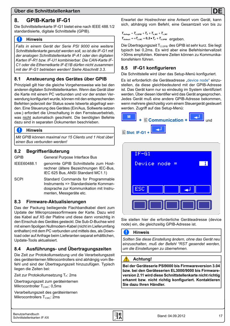
8.5 IF-G1 konfigurierenDie Schnittstelle wird über das Setup-Menü konfiguriert.Es ist erforderlich die Geräteadresse „device node“ einzu-stellen, da diese gleichbedeutend mit der GPIB-Adresse ist. Das Gerät kann nur so eindeutig im System identifiziert werden. Über diesen Identifier wird das Gerät angesprochen. Jedes Gerät muß eine andere GPIB-Adresse bekommen, wenn mehrere gleichzeitig vom einem Steuergerät gesteuert werden. Zugriff auf das Setup-Menü:
M + Communication + und
Slot: IF-G1 +
Sie stellen hier die erforderliche Geräteadresse (device node) ein, die gleichzeitig GPIB-Adresse ist.
HinweisSollten Sie diese Einstellung ändern, ohne das Gerät neu einzuschalten, muß der Befehl *RST gesendet werden, um die Einstellungen zu übernehmen.
Achtung!Bei der Geräteserie PSI9000 bis Firmwareversion 3.04 bzw. bei den Geräteserien EL3000/9000 bis Firmware-version 2.11 wird diese Schnittstellenkarte nicht richtig erkannt bzw. nicht richtig konfiguriert. Kontaktieren Sie dazu Ihren Händler.
Über die Schnittstellenkarten
18BenutzerhandbuchSchnittstellenkarten IF-XX
DE
Stand: 04.09.2012
Über die Schnittstellenkarten
9. Ethernetkarte IF-E1BAchtung!
Ab Juni 2011 wird nur noch der Typ IF-E1B vertrieben und dieser Abschnitt bezieht sich nicht mehr auf den vorherigen Typen IF-E1 und IF-E2.
Die Ethernet- bzw. Netzwerkkarte verbindet das Gerät direkt mit einem Hostrechner (PC) oder über Hubs/Switches. Je nach Verbindungsart ist ein Patchkabel oder ein Crossover-Kabel zu verwenden. Die Ethernetschnittstelle mit ihrer RJ45-Buchse kann nicht konfiguriert werden und arbeitet automatischer Erkennung der Verbindungsgeschwindigkeit von 10 oder 100 MBit. Welche eingestellt wird, bestimmt der Hostrechner bzw. die Netzwerkhardware.
HinweisDie Übertragungsgeschwindigkeit für Ethernet (10Mbit oder 100MBit) ist nicht gleichzusetzen mit der Geschwin-digkeit, mit der mit dem Gerät selbst kommuniziert werden kann. Diese ist intern auf 100kBit festgelegt und daraus ergeben sich bestimmte Antwort- und Ausführungszeiten. Siehe auch „8.4 Ausführungs- und Übertragungszeiten“ sowie die technischen Daten der Schnittstelle in „2. Tech-nische Daten“.
9.1 Vorbereitung / Hinweise zum BetriebVor der Inbetriebnahme bzw. für den Betrieb der Ethernet-karte müssen ein paar Dinge beachtet werden:• Ist eine Netzwerkkarte im Gerät in Betrieb, sollte möglichst
immer ein Netzwerkkabel gesteckt sein.• Wenn am Gerät die Netzwerkeinstellungen verändert wer-
den (abhängig vom Gerätemodell), dann werden diese nur wirksam, wenn das Gerät aus- und wieder eingeschaltet wird.
• Wenn über die Webseite der Netzwerkkarte die Netzwerk-parameter verändert und übernommen werden, werden diese sofort wirksam.
• Der Port für die Kommunikation mit dem Gerät über TCP/IP kann nur über die Webseite verändert werden und wird dau-erhaft auf der Ethernetkarte gespeichert, im Gegensatz zu den Netzwerkparametern, die im Gerät gespeichert werden.
• Bei Kommunikation über TCP/IP sollte die Webseite ge-schlossen sein, da die Webseite zusätzlichen Datenverkehr mit der Ethernetkarte erzeugt und den anderen Zugriff stören kann.
• Die LEDs an der RJ45-Buchse sind außer Betrieb, um die galvanische Trennung zu garantieren
• SCPI-Nachrichten, vom Gerät kommend, enthalten immer ein Endezeichen 0xA (10) im String1
• Bei Firmwareversionen <2.10 arbeitet die Karte standard-mäßig mit DHCP und bekommt, solange DHCP im Netzwerk aktiviert ist, automatisch eine andere IP vom DHCP-Server zugewiesen und die im Gerät eingestellte wird ignoriert. Da diese zunächst unbekannt ist, kann die Karte nicht abge-sprochen werden.
9.2 Ethernetkarte konfigurieren
9.2.1 Am Gerät
HinweisEinstellungen bezüglich der Netzwerkparameter sind nicht bei jedem Gerät im Setup möglich und müssen dann von außerhalb vorgenommen werden. In dem Fall bitte weiter-lesen in Abschnitt 9.2.2.
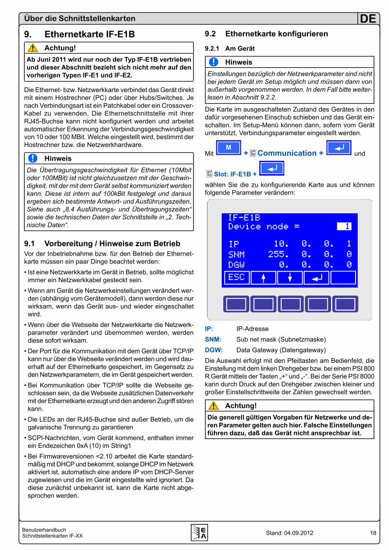
Die Karte im ausgeschalteten Zustand des Gerätes in den dafür vorgesehenen Einschub schieben und das Gerät ein-schalten. Im Setup-Menü können dann, sofern vom Gerät unterstützt, Verbindungsparameter eingestellt werden.
Mit M
+Communication + und
Slot: IF-E1B + wählen Sie die zu konfigurierende Karte aus und können folgende Parameter verändern:
IP: IP-AdresseSNM: Sub net mask (Subnetzmaske)DGW: Data Gateway (Datengateway)Die Auswahl erfolgt mit den Pfeiltasten am Bedienfeld, die Einstellung mit dem linken Drehgeber bzw. bei einem PSI 800 R Gerät mittels der Tasten „+“ und „-“. Bei der Serie PSI 8000 kann durch Druck auf den Drehgeber zwischen kleiner und großer Einstellschrittweite der Zahlen gewechselt werden.
Achtung!Die generell gültigen Vorgaben für Netzwerke und de-ren Parameter gelten auch hier. Falsche Einstellungen führen dazu, daß das Gerät nicht ansprechbar ist.
19BenutzerhandbuchSchnittstellenkarten IF-XX
DE
Stand: 04.09.2012
Über die Schnittstellenkarten
9.2.2 Über das IP-Config-ToolBei Geräteserien, wo die Verbindungsparameter nicht am Gerät eingestellt werden können, kann dies über den USB-Port der Ethernetkarte, das mitgelieferte USB-Kabel und das „IP-Config Tool“ erledigt werden, das auf der beiliegenden CD im Ordner \software bzw. auf unserer Webseite zu finden ist. Dabei ist auf korrekte Treiberinstallation des USB-Ports zu achten. Vor der Benutzung von IP-Config bzw. des USB-Ports müs-sen die auf der Schnittstellenkarte befindlichen Steckbrücken (Jumper) in die Position NORM gesteckt werden.Ist der Treiber richtig installiert, sucht und erkennt das Programm das Gerät (Auswahl über eine Dropdown-Liste) und die Netzwerkparameter können ausgelesen (READ CONFIG), eingestellt und in das Gerät geschrieben (WRITE CONFIG) werden. Nach einer Änderung der Parameter muß das Gerät einmal aus- und wieder eingeschaltet werden und kann dann über die neuen Netzwerkparameter angesprochen werden.
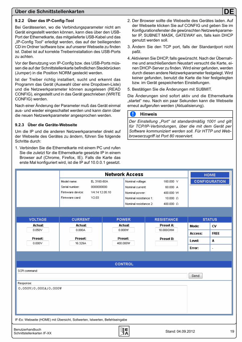
9.2.3 Über die Geräte-WebseiteUm die IP und die anderen Netzwerkparameter direkt auf der Webseite des Gerätes zu ändern, führen Sie folgende Schritte durch:1. Verbinden Sie die Ethernetkarte mit einem PC und rufen
Sie die zuletzt für die Ethernetkarte gesetzte IP in einem Browser auf (Chrome, Firefox, IE). Falls die Karte das erste Mal konfiguriert wird, ist die IP auf 10.0.0.1 gesetzt.
2. Der Browser sollte die Webseite des Gerätes laden. Auf der Webseite klicken Sie auf CONFIG und geben Sie im Konfigurationsfenster die gewünschten Netzwerkparame-ter IP, SUBNET MASK, GATEWAY ein, falls kein DHCP genutzt werden soll.
3. Ändern Sie den TCP port, falls der Standardport nicht paßt.
4. Aktivieren Sie DHCP, falls gewünscht. Nach der Übernah-me und anschließendem Neustart versucht die Karte, ei-nen DHCP-Server zu finden. Wird einer gefunden, werden durch diesen andere Netzwerkparameter festgelegt. Wird keiner gefunden, benutzt die Karte die hier festgelegten bzw. im Gerät gespeicherten Einstellungen.
5. Bestätigen Sie die Änderungen mit SUBMIT.Die Änderungen sind sofort aktiv und die Ethernetkarte „startet“ neu. Nach ein paar Sekunden kann die Webseite erneut aufgerufen werden (Aktualisierung).
HinweisDer Einstellung „Port“ ist standardmäßig 1001 und gilt für TCP/IP-Verbindungen, über die mit dem Gerät per Software kommuniziert werden soll. Für HTTP und Web-browserzugriff ist Port 80 reserviert.
IF-Ex: Webseite (HOME) mit Übersicht, Sollwerten, Istwerten, Befehlseingabe
20BenutzerhandbuchSchnittstellenkarten IF-XX
DE
Stand: 04.09.2012
Über die Schnittstellenkarten
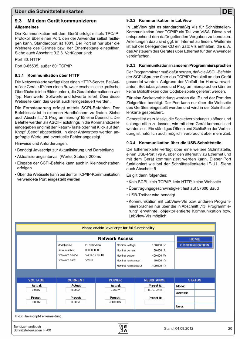
9.3 Mit dem Gerät kommunizierenAllgemeinesDie Kommunikation mit dem Gerät erfolgt mittels TPC/IP-Protokoll über einen Port, den der Anwender selbst festle-gen kann. Standardport ist 1001. Der Port ist nur über die Webseite des Gerätes bzw. der Ethernetkarte einstellbar. Siehe auch Abschnitt 9.2.3. Verfügbar sind:Port 80: HTTPPort 0-65535, außer 80: TCP/IP
9.3.1 Kommunikation über HTTPDie Netzwerkkarte verfügt über einen HTTP-Server. Bei Auf-ruf der Geräte-IP über einen Browser erscheint eine grafische Oberfläche (siehe Bilder unten), die Geräteinformationen wie Typ, Nennwerte, Sollwerte und Istwerte liefert. Über diese Webseite kann das Gerät auch ferngesteuert werden.Die Fernsteuerung erfolgt mittels SCPI-Befehlen. Der Befehlssatz ist in externen Handbüchern zu finden. Siehe auch Abschnitt „13. Programmierung“ für eine Übersicht. Die Befehle werden als ASCII-Textstrings in die Kommandozeile eingegeben und mit der Return-Taste oder mit Klick auf den Knopf „Send“ abgeschickt. In einer Antwortbox werden an-gefragte Werte und eventuelle Fehler angezeigt.Hinweise und Anforderungen:• Benötigt Javascript zur Aktualisierung und Darstellung• Aktualisierungsintervall (Werte, Status): 200ms• Eingabe der SCPI-Befehle kann auch in Kleinbuchstaben
erfolgen• Über die Webseite kann bei der für TCP/IP-Kommunikation
verwendete Port eingestellt werden
9.3.2 Kommunikation in LabViewIn LabView gibt es standardmäßig VIs für Schnittstellen-Kommunikation über TCP/IP als Teil von VISA. Diese sind entsprechend den dafür geltenden Vorgaben zu benutzen. Anleitungen dazu sind ggf. im Internet zu finden. Weiterhin ist auf der beliegenden CD ein Satz VIs enthalten, die u. A. das Ansteuern des Gerätes über Ethernet für den Anwender vereinfachen.
9.3.3 Kommunikation in anderen ProgrammiersprachenDer Programmierer muß dafür sorgen, daß die ASCII-Befehle der SCPI-Sprache über das TCP/IP-Protokoll an das Gerät gesendet werden. Aufgrund der Vielfalt der Hardwarevari-anten, Betriebssysteme und Programmiersprachen können keine Bibliotheken oder Codebeispiele geliefert werden.Für eine Socketverbindung werden die IP und der Port des Zielgerätes benötigt. Der Port kann nur über die Webseite des Gerätes eingestellt werden und wird in der Schnittstel-lenkarte gespeichert.Generell ist es zulässig, die Socketverbindung zu öffnen und solange offen zu lassen, wie mit dem Gerät kommuniziert werden soll. Ein ständiges Öffnen und Schließen der Verbin-dung ist natürlich auch möglich, verbraucht aber mehr Zeit.
9.3.4 Kommunikation über die USB-SchnittstelleDie Ethernetkarte verfügt über eine weitere Schnittstelle, einen USB-Port Typ A, über den alternativ zu Ethernet und mit dem Gerät kommuniziert werden kann. Dieser Port funktioniert wie bei der Schnittstellenkarte IF-U1. Siehe auch Abschnitt 5.Es gilt dann folgendes:• Kein SCPI, kein TCP/IP, kein HTTP, keine Webseite• Übertragungsgeschwindigkeit fest auf 57600 Baud• USB-Treiber wird benötigt• Kommunikation mit LabView-VIs bzw. anderen Program-
miersprachen nur über die in Abschnitt „13. Programmie-rung“ erwähnte, objektorientierte Kommunikation bzw. LabView-VIs möglich.
IF-Ex: Javascript-Fehlermeldung

21BenutzerhandbuchSchnittstellenkarten IF-XX
DE
Stand: 04.09.2012
9.4 FirmwareaktualisierungDer zusätzliche USB-Port dient weiterhin zur Firmwareak-tualisierung des Gerätes bzw. der Netzwerkkarte selbst. Für die Firmwareaktualisierung werden ein entsprechendes Updatetool und die passende Firmware benötigt, beides ist beim Hersteller des Gerätes zu beziehen.
9.5 Hilfe bei KommunikationsproblemenProblem: Gerät ist nicht mehr ansprechbarFür den Fall, daß die Verbindung zum Gerät einmal hängen sollte bzw. das Gerät über IP:Port nicht mehr ansprechbar ist, kann die Karte mittels des Reset-Tasters zurückgesetzt werden. Die Karte startet nach Betätigung des Tasters neu und initiali-siert die Netzwerkverbindung mit den im Gerät gespeicherten Netzwerkparametern. Nach einigen Sekunden sollte sie wieder ansprechbar sein
Problem: IP des Gerätes ist nicht (mehr) bekanntBei einem Gerät mit grafischem Display (PSI 8000, PSI 800R) kann die IP im Setupmenü aufgerufen und eingestellt werden.Andere Modelle, wie z. B. ein PS 8000 T, können die eigene IP nicht anzeigen. Hierfür ist das auf der beliegenden Tools-CD befindliche Programm „IP-Config“ zu benutzen. Über die USB-Verbindung an der Ethernetkarte (Jumper in Position NORM) können die Netzwerkparameter ausgelesen, ggf. verändert und wieder in das Gerät geschrieben werden.
Problem: Das Gerät ist über dessen IP nicht ansprechbarDas kann verschiedene Gründe haben:1. Die Ethernetkarte wurde vom Gerät nicht erkanntDieses Problem äußert sich darin, daß die Ethernetkarte alle paar Sekunden rebootet und somit die Netzwerkverbindung ständig hergestellt und wieder getrennt wird. Prüfen Sie zunächst, ob bei Gerät...• Last EL 3000/EL 9000 im Setup angezeigt wird „Card
found: IF-E1 (Ethernet)• Netzgerät PSI 8000 oder PSI 800 R im Menü „Communi-
cation“ angezeigt wird „Slot: IF-E1“• Netzgerät PS 8000 im Setupmenü angezeigt wird „Device
node“Falls nicht, besteht entweder ein Defekt des Karteneinschubs des Gerätes, ein Defekt der Schnittstellenkarte oder die Karte ist nicht richtig installiert worden.2. Die IP des Gerätes liegt in einem anderen NetzwerksegmentÜberprüfen Sie IP und Netzwerkmaske und korrigieren Sie diese ggf. Überprüfen Sie auch die Routing-Einstellungen des PCs, falls zwei Netzwerkports im PC vorhanden sind.3. Der TCP-Port ist automatisch geschlossen wordenDas keep-alive-Timeout der IF-E1B beträgt 10min. Wenn während dieser Zeit kein Datenverkehr stattfindet, wird die Verbindung von der Geräteseite her geschlossen.
Über die Schnittstellenkarten
4. Das Gerät hat eine völlig andere IPWenn DHCP aktiviert wurde und sich ein DHCP-Server im Netzwerk befindet, bekommt die Karte eine andere IP zugewiesen als über die Webseite, am Gerät oder mittels Tool IP-Config eingestellt wurde. DHCP hat hierbei Priorität. Um DHCP ggf. wieder abzustellen, müssen Sie die aktuelle IP erst herausfinden. Das können Sie entweder mit einem Netzwerkscannertool, das Ihnen neben den IPs der gefun-denen Netzwerkteilnehmer auch deren MAC-Adresse auf-listet, anhand derer die Karte eindeutig identifizierbar wird (Aufkleber an Karte). Oder, falls die Karte an einem Switch/Router angeschlossen ist, öffnen Sie die Weboberfläche des Switches/Router und die dortige Liste der angeschlossene-nen Gerät, wo auch wieder die MAC-Adresse gelistet sein sollte. Rufen Sie die durch die MAC-Adresse aufgefundene IP im Browser auf und schalten Sie DHCP ggf. über die Geräte-Webseite aus. Problem: Die LEDs am Netzwerkport leuchten nichtDas ist kein Fehler. Das ist beabsichtigt, damit die galva-nische Trennung der Schnittstellenkarte zum Gerät hin gewährleistet werden kann.
Problem: Bei Verwendung von zwei oder mehr IF-E1B im Netzwerk sind ein oder mehrere Geräte nicht an-sprechbarDas kann bei älteren Firmwareversion bis 2.08 der Ether-netkarte auftreten. Die Karte nutzt dann nicht die einpro-grammierte MAC-Adresse, so wie aufgedruckt, sondern eine Standard-MAC-Adresse, die dann mehreren Karten mit demselben Problem auch gleich ist. Abhilfe schafft da nur ein Firmwareupdate der Ethernetkarte(n).Ab Firmware 2.09 und für den Fall, daß die Karte die pro-grammierte MAC-Adresse nicht setzen bzw. benutzen kann, generiert sie eine eindeutige aus einem festen, immer glei-chen Teil (erste 3 Bytes) und der eigenen Seriennummer.
22BenutzerhandbuchSchnittstellenkarten IF-XX
DE
Stand: 04.09.2012
Über die Schnittstellenkarten
10. Profibuskarte IF-PB1Profibus steht für „Process Field Bus“ und ist ein hauptsäch-lich europäischer Standard für die Feldbus-Kommunikation in der Automatisierungstechnik.Die Profibuskarte ermöglicht es, bis zu 32 damit bestückte Geräte an einem Bussegment zu betreiben, ohne daß wei-tere technische Maßnahmen nötig sind. Busabschluß von Endgeräten wird, die bei diesem Bus typisch, über schaltbare Abschlußwiderstände erledigt, die in den Profibussteckern integriert sind.Ein mit der IF-PB1 bestücktes Gerät erkennt die Schnitt-stellenkarte automatisch und bietet im Gerätesetup (siehe dazu das jeweilige Gerätehandbuch) die Einstellung der Profibusadresse (1...126) an. Diese Adresse benötigt der Profibus-Slavecontroller. Sobald das Gerät mit dem Bus verbunden wird, wird es angemeldet und eingebunden. Auf der Steuerungsseite, in der Regel ein PC, wird dann eine sog. GSD-Datei (Generic Station Description, auch genannt Geräte-Stammdatei) in die Profibus-Mastersoftware gela-den, die das Gerät und dessen über Profibus ausführbare Funktionen definiert.
10.1 ÜbertragungsgeschwindigkeitDie max. Übertragungsgeschwindigkeit für den Profibus-Slavecontroller (12Mbit) ist nicht gleichzusetzen mit der Geschwindigkeit, mit der mit dem Gerät selbst kommuniziert werden kann. Diese ist intern auf 57600 Baud festgelegt und dementsprechend ergeben sich Antwort- und Ausfüh-rungszeiten. Siehe auch Abschnitt „8.4 Ausführungs- und Übertragungszeiten“.
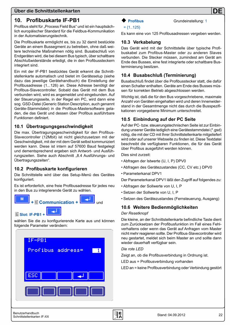
10.2 Profibuskarte konfigurierenDie Schnittstelle wird über das Setup-Menü des Gerätes konfiguriert.Es ist erforderlich, eine freie Profibusadresse für jedes neu in den Bus zu integrierende Gerät zu wählen.
M +Communication + und
Slot: IF-PB1 + wählen Sie die zu konfigurierende Karte aus und können folgende Parameter verändern:
Profibus Grundeinstellung: 1 = 1..125 Es kann eine von 125 Profibusadressen vergeben werden.
10.3 VerkabelungDas Gerät wird mit der Schnittstelle über typische Profi-buskabel zum Profibus-Master oder zu anderen Slaves verbunden. Die Stecker müssen, zumindest am Gerät am Ende des Busses, eine fest integrierte oder schaltbare Bus-terminierung besitzen.
10.4 Busabschluß (Terminierung)Busabschluß findet über die Profibusstecker statt, die dafür einen Schalter enthalten. Geräte am Ende des Busses müs-sen für korrekten Betrieb abgeschlossen werden.Wichtig ist, daß die für den Bus vorgeschriebene, maximale Anzahl von Geräten eingehalten wird und deren Innenwider-stand in der Gesamtmenge nicht das durch die Busspezifi-kationen vorgegebene Minimum unterschreitet.
10.5 Einbindung auf der PC SeiteAuf der PC- bzw. steuerungstechnischen Seite ist zur Einbin-dung unserer Geräte lediglich eine Gerätestammdatei (*.gsd) nötig, die mit der CD mit Ihrer Schnittstellenkarte mitgeliefert wird oder auf unserer Webseite zu finden ist. Diese Textdatei beschreibt die verfügbaren Funktionen, die für das Gerät über Profibus ausgeführt werden können.Dies sind zurzeit:• Abfragen der Istwerte (U, I, P) DPV0 • Abfragen des Gerätezustandes (CC, CV etc.) DPV0• Parameterkanal DPV1Der Parameterkanal DPV1 läßt den Zugriff auf folgendes zu:• Abfragen der Sollwerte von U, I, P• Setzen der Sollwerte von U, I, P• Setzen des Gerätezustandes (Fernsteuerung, Ausgang)
10.6 Weitere BedienmöglichkeitenDer ResetknopfDie kleine, an der Schnittstellenkarte befindliche Taste dient zum Zurücksetzen der Profibusfunktion im Fall eines Fehl-verhaltens oder wenn das Gerät auf Anfragen vom Master nicht mehr reagieren sollte. Der Profibus-Slavecontroller wird neu gestartet, meldet sich beim Master an und sollte dann wieder dauerhaft verfügbar sein.Die rote LEDZeigt an, ob die Profibusverbindung in Ordnung ist.LED aus = Profibusverbindung vorhandenLED an = keine Profibusverbindung oder Verbindung gestört
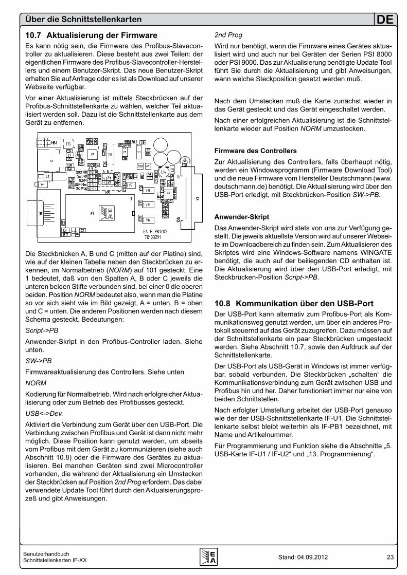
23BenutzerhandbuchSchnittstellenkarten IF-XX
DE
Stand: 04.09.2012
Über die Schnittstellenkarten
10.7 Aktualisierung der FirmwareEs kann nötig sein, die Firmware des Profibus-Slavecon-troller zu aktualisieren. Diese besteht aus zwei Teilen: der eigentlichen Firmware des Profibus-Slavecontroller-Herstel-lers und einem Benutzer-Skript. Das neue Benutzer-Skript erhalten Sie auf Anfrage oder es ist als Download auf unserer Webseite verfügbar. Vor einer Aktualisierung ist mittels Steckbrücken auf der Profibus-Schnittstellenkarte zu wählen, welcher Teil aktua-lisiert werden soll. Dazu ist die Schnittstellenkarte aus dem Gerät zu entfernen.
Blatt 1 / 2
Die Steckbrücken A, B und C (mitten auf der Platine) sind, wie auf der kleinen Tabelle neben den Steckbrücken zu er-kennen, im Normalbetrieb (NORM) auf 101 gesteckt. Eine 1 bedeutet, daß von den Spalten A, B oder C jeweils die unteren beiden Stifte verbunden sind, bei einer 0 die oberen beiden. Position NORM bedeutet also, wenn man die Platine so vor sich sieht wie im Bild gezeigt, A = unten, B = oben und C = unten. Die anderen Positionen werden nach diesem Schema gesteckt. Bedeutungen:Script->PBAnwender-Skript in den Profibus-Controller laden. Siehe unten.SW->PBFirmwareaktualisierung des Controllers. Siehe untenNORMKodierung für Normalbetrieb. Wird nach erfolgreicher Aktua-lisierung oder zum Betrieb des Profibusses gesteckt.USB<->Dev.Aktiviert die Verbindung zum Gerät über den USB-Port. Die Verbindung zwischen Profibus und Gerät ist dann nicht mehr möglich. Diese Position kann genutzt werden, um abseits vom Profibus mit dem Gerät zu kommunizieren (siehe auch Abschnitt 10.8) oder die Firmware des Gerätes zu aktua-lisieren. Bei manchen Geräten sind zwei Microcontroller vorhanden, die während der Aktualisierung ein Umstecken der Steckbrücken auf Position 2nd Prog erfordern. Das dabei verwendete Update Tool führt durch den Aktualsierungspro-zeß und gibt Anweisungen.
2nd ProgWird nur benötigt, wenn die Firmware eines Gerätes aktua-lisiert wird und auch nur bei Geräten der Serien PSI 8000 oder PSI 9000. Das zur Aktualisierung benötigte Update Tool führt Sie durch die Aktualisierung und gibt Anweisungen, wann welche Steckposition gesetzt werden muß.
Nach dem Umstecken muß die Karte zunächst wieder in das Gerät gesteckt und das Gerät eingeschaltet werden.Nach einer erfolgreichen Aktualisierung ist die Schnittstel-lenkarte wieder auf Position NORM umzustecken.
Firmware des ControllersZur Aktualisierung des Controllers, falls überhaupt nötig, werden ein Windowsprogramm (Firmware Download Tool) und die neue Firmware vom Hersteller Deutschmann (www.deutschmann.de) benötigt. Die Aktualisierung wird über den USB-Port erledigt, mit Steckbrücken-Position SW->PB.
Anwender-SkriptDas Anwender-Skript wird stets von uns zur Verfügung ge-stellt. Die jeweils aktuellste Version wird auf unserer Websei-te im Downloadbereich zu finden sein. Zum Aktualisieren des Skriptes wird eine Windows-Software namens WINGATE benötigt, die auch auf der beiliegenden CD enthalten ist. Die Aktualisierung wird über den USB-Port erledigt, mit Steckbrücken-Position Script->PB.
10.8 Kommunikation über den USB-PortDer USB-Port kann alternativ zum Profibus-Port als Kom-munikationsweg genutzt werden, um über ein anderes Pro-tokoll steuernd auf das Gerät zuzugreifen. Dazu müssen auf der Schnittstellenkarte ein paar Steckbrücken umgesteckt werden. Siehe Abschnitt 10.7, sowie den Aufdruck auf der Schnittstellenkarte.Der USB-Port als USB-Gerät in Windows ist immer verfüg-bar, sobald verbunden. Die Steckbrücken „schalten“ die Kommunikationsverbindung zum Gerät zwischen USB und Profibus hin und her. Daher funktioniert immer nur eine von beiden Schnittstellen.Nach erfolgter Umstellung arbeitet der USB-Port genauso wie der der USB-Schnittstellenkarte IF-U1. Die Schnittstel-lenkarte selbst bleibt weiterhin als IF-PB1 bezeichnet, mit Name und Artikelnummer. Für Programmierung und Funktion siehe die Abschnitte „5. USB-Karte IF-U1 / IF-U2“ und „13. Programmierung“.
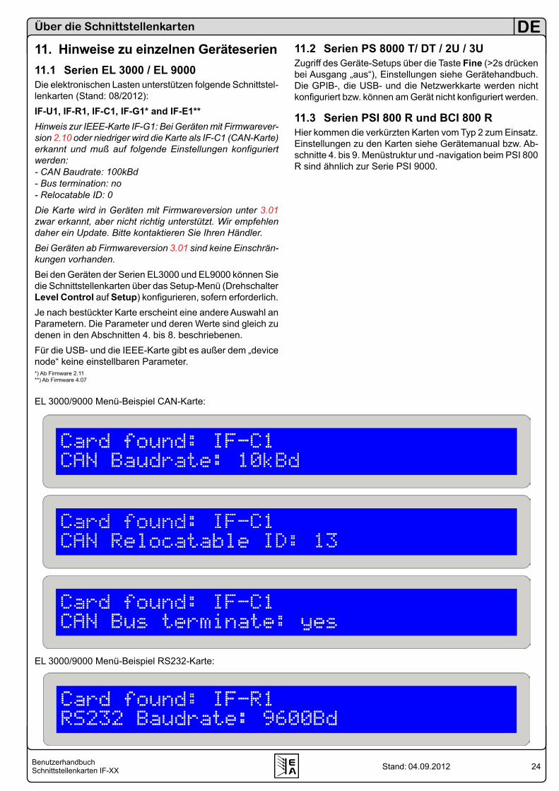
24BenutzerhandbuchSchnittstellenkarten IF-XX
DE
Stand: 04.09.2012
11. Hinweise zu einzelnen Geräteserien11.1 Serien EL 3000 / EL 9000Die elektronischen Lasten unterstützen folgende Schnittstel-lenkarten (Stand: 08/2012):IF-U1, IF-R1, IF-C1, IF-G1* and IF-E1**Hinweis zur IEEE-Karte IF-G1: Bei Geräten mit Firmwarever-sion 2.10 oder niedriger wird die Karte als IF-C1 (CAN-Karte) erkannt und muß auf folgende Einstellungen konfiguriert werden:- CAN Baudrate: 100kBd- Bus termination: no- Relocatable ID: 0Die Karte wird in Geräten mit Firmwareversion unter 3.01 zwar erkannt, aber nicht richtig unterstützt. Wir empfehlen daher ein Update. Bitte kontaktieren Sie Ihren Händler.Bei Geräten ab Firmwareversion 3.01 sind keine Einschrän-kungen vorhanden.Bei den Geräten der Serien EL3000 und EL9000 können Sie die Schnittstellenkarten über das Setup-Menü (Drehschalter Level Control auf Setup) konfigurieren, sofern erforderlich. Je nach bestückter Karte erscheint eine andere Auswahl an Parametern. Die Parameter und deren Werte sind gleich zu denen in den Abschnitten 4. bis 8. beschriebenen.Für die USB- und die IEEE-Karte gibt es außer dem „device node“ keine einstellbaren Parameter.*) Ab Firmware 2.11 **) Ab Firmware 4.07
11.2 Serien PS 8000 T/ DT / 2U / 3UZugriff des Geräte-Setups über die Taste Fine (>2s drücken bei Ausgang „aus“), Einstellungen siehe Gerätehandbuch. Die GPIB-, die USB- und die Netzwerkkarte werden nicht konfiguriert bzw. können am Gerät nicht konfiguriert werden.
11.3 Serien PSI 800 R und BCI 800 RHier kommen die verkürzten Karten vom Typ 2 zum Einsatz. Einstellungen zu den Karten siehe Gerätemanual bzw. Ab-schnitte 4. bis 9. Menüstruktur und -navigation beim PSI 800 R sind ähnlich zur Serie PSI 9000.
Über die Schnittstellenkarten
EL 3000/9000 Menü-Beispiel CAN-Karte:
EL 3000/9000 Menü-Beispiel RS232-Karte:
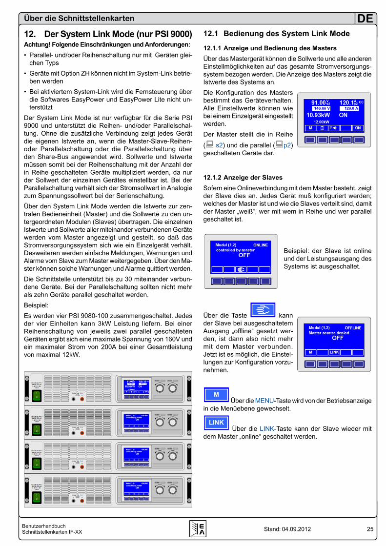
25BenutzerhandbuchSchnittstellenkarten IF-XX
DE
Stand: 04.09.2012
12. Der System Link Mode (nur PSI 9000)Achtung! Folgende Einschränkungen und Anforderungen:• Parallel- und/oder Reihenschaltung nur mit Geräten glei-
chen Typs• Geräte mit Option ZH können nicht im System-Link betrie-
ben werden• Bei aktiviertem System-Link wird die Fernsteuerung über
die Softwares EasyPower und EasyPower Lite nicht un-terstützt
Der System Link Mode ist nur verfügbar für die Serie PSI 9000 und unterstützt die Reihen- und/oder Parallelschal-tung. Ohne die zusätzliche Verbindung zeigt jedes Gerät die eigenen Istwerte an, wenn die Master-Slave-Reihen- oder Parallelschaltung oder die Parallelschaltung über den Share-Bus angewendet wird. Sollwerte und Istwerte müssen somit bei der Reihenschaltung mit der Anzahl der in Reihe geschalteten Geräte multipliziert werden, da nur der Sollwert der einzelnen Gerätes einstellbar ist. Bei der Parallelschaltung verhält sich der Stromsollwert in Analogie zum Spannungssollwert bei der Serienschaltung. Über den System Link Mode werden die Istwerte zur zen-tralen Bedieneinheit (Master) und die Sollwerte zu den un-tergeordneten Modulen (Slaves) übertragen. Die einzelnen Istwerte und Sollwerte aller miteinander verbundenen Geräte werden vom Master angezeigt und gestellt, so daß das Stromversorgungssystem sich wie ein Einzelgerät verhält. Desweiteren werden einfache Meldungen, Warnungen und Alarme vom Slave zum Master weitergegeben. Über den Ma-ster können solche Warnungen und Alarme quittiert werden.Die Schnittstelle unterstützt bis zu 30 miteinander verbun-dene Geräte. Bei der Parallelschaltung sollten nicht mehr als zehn Geräte parallel geschaltet werden.Beispiel:Es werden vier PSI 9080-100 zusammengeschaltet. Jedes der vier Einheiten kann 3kW Leistung liefern. Bei einer Reihenschaltung von jeweils zwei parallel geschalteten Geräten ergibt sich eine maximale Spannung von 160V und ein maximaler Strom von 200A bei einer Gesamtleistung von maximal 12kW.
12.1 Bedienung des System Link Mode
12.1.1 Anzeige und Bedienung des MastersÜber das Mastergerät können die Sollwerte und alle anderen Einstellmöglichkeiten auf das gesamte Stromversorgungs-system bezogen werden. Die Anzeige des Masters zeigt die Istwerte des Systems an. Die Konfiguration des Masters bestimmt das Geräteverhalten. Alle Einstellwerte können wie bei einem Einzelgerät eingestellt werden.Der Master stellt die in Reihe
( s2) und die parallel (p2) geschalteten Geräte dar.
12.1.2 Anzeige der SlavesSofern eine Onlineverbindung mit dem Master besteht, zeigt der Slave dies an. Jedes Gerät muß konfiguriert werden; welches der Master ist und wie die Slaves verteilt sind, damit der Master „weiß“, wer mit wem in Reihe und wer parallel geschaltet ist.
Beispiel: der Slave ist online und der Leistungsausgang des Systems ist ausgeschaltet.
Über die Taste kann der Slave bei ausgeschaltetem Ausgang „offline“ gesetzt wer-den, ist dann also nicht mehr mit dem Master verbunden. Jetzt ist es möglich, die Einstel-lungen zur Konfiguration vorzu-nehmen.
M Über die MENU-Taste wird von der Betriebsanzeige
in die Menüebene gewechselt.
LINK Über die LINK-Taste kann der Slave wieder mit
dem Master „online“ geschaltet werden.
Über die Schnittstellenkarten

26BenutzerhandbuchSchnittstellenkarten IF-XX
DE
Stand: 04.09.2012
12.1.3 Spezielle Alarme, Warnungen und Meldungen
M S Der Master meldet, dass nicht mehr alle Slaves online sind.
Allgemeiner Alarm vom SlaveDieser Alarm wird ausgelöst, wenn ein Slave nicht mehr adressiert werden kann während der Master den Ausgang eingeschaltet hatte. Zum Beispiel wenn die Verbindung unterbrochen oder der Slave über den Netzschalter ausge-schaltet wurde.
S-PH Ein Alarm oder
S-PH eine Warnung mit „Auto ON“ Funktion
wird gemeldet, wenn die Verbindung zum Slave fehlt, falls der Slave ausgeschaltet wurde oder seine Spannungsver-sorgung weggefallen ist. PH = Phasenausfall.Ein Warnung mit „Auto ON“ Funktion schaltet den Ausgang ab bis der Fehler behoben ist. Das Stromversorgungssystem schaltet den Ausgang automatisch wieder ein. Der Fehler ist zu quittieren und wird, falls er nach der Quittierung immer noch besteht, in eine Meldung umgewandelt. Die Meldung erlischt, sobald der Fehler behoben ist bzw. entfällt.Ob nun ein Alarm oder eine Warnung mit „Auto ON“ ausge-führt wird, hängt von der Einstellung „Wiedereinschaltung bei Power On“ ab (siehe Benutzerhandbuch PSI 9000, Abschnitt „Betriebsparameter definieren“).
Power ON Grundeinstellung: OFF = OFF Leistungsausgang bleibt nach Netzwiederkehr
oder beim Einschalten des Gerätes ausge-schaltet.
= restore Leistungsausgang schaltet sich nach Netz-wiederkehr oder beim Einschalten des Ge-rätes automatisch ein, wenn er vor Wegfall des Netz oder vor dem letzten Ausschalten eingeschaltet war.
S-OT Ein Alarm oder
S-OT eine Warnung mit „Auto ON“ Funktion
wurde ausgelöst, da ein oder mehrere Slaves eine Übertem-peratur ihres Leistungsteils festgestellt haben und melden.Ob nun ein Alarm oder eine Warnung mit „Auto ON“ ausge-führt wird, hängt von der Einstellung „Wiedereinschaltung bei Power On“ ab (siehe Benutzerhandbuch PSI 9000, Abschnitt „Betriebsparameter definieren“).
OT disappear Grundeinstellung: auto ON = OFF Leistungsausgang bleibt auch nach Abkühlen
des Gerätes ausgeschaltet. = Auto ON Leistungsausgang schaltet sich nach Abküh-
len des Gerätes bzw. nach Unterschreitung der Übertemperaturschwelle automatisch wieder ein.
Über die Schnittstellenkarten
S-OV
Bei einem oder mehreren Slaves hat der OVP (Overvoltage Protection) eine Alarmmeldung ausgelöst. Der Ausgang wird abgeschaltet. Er kann erst nach Quittierung der Meldung wieder eingeschaltet werden.
12.2 Konfiguration des System Link ModeUm den System Link Mode nutzen zu können, müssen die zusätzlichen Schnittstellen (SIO2) auf den IF-U1 oder IF-R1-Karten miteinander, unabhängig von der Serien- oder Parallelschaltung, über ein handelsübliches Patchkabel CAT5 mit RJ45 Steckern verbunden werden. Die Endgeräte erhalten einen Busabschluß, der über die Parameterseite eingestellt werden muss.
Slot A|B: IF-R1 IF-U1 +SIO2 Grundeinstellung: not used = not available Die SIO2 Schnittstelle ist nicht verfügbar. = not used Die SIO2 Schnittstelle wird nicht verwen-
det. = Master|Slave Das Gerät wird als „Master“ oder Slave defi-
niert. Die folgenden zwei Parameter sind nur sichtbar, wenn das Gerät als Master definiert wurde.
Matrix of modules Bei den nachfolgenden Einstellungen ist dem Master bekannt zugeben, wieviele Geräte in Reihe und/oder parallel liegen.
serial Grundeinstellung: 1 =1..x Die Anzahl der in Reihe geschalteten Ge-
räte ist hier anzugeben. Eine 2 bedeutet, daß 2 Geräte verbunden sind usw.
Es gilt die maximal zulässige Isolationsspannung zu beachten, wodurch nicht beliebig viele Geräte in Reihe geschaltet werden dürfen!
parallel Grundeinstellung: 1 =1..30 Die Anzahl der parallel geschalteten Geräte
ist hier anzugeben, unabhängig davon ob di-rekt zum Master oder nicht. Eine 2 bedeutet, daß 2 Geräte parallel verbunden sind usw.)
Die zwei folgenden Parameter erscheinen nur, wenn das Gerät als Slave definiert wurde:
Position of moduleBei den nachfolgenden Einstellungen wird die Position des Gerätes in der Reihen- und Parallelschaltung fest-gelegt. Innerhalb des Stromversorgungssystems darf eine Position nur einmal vergeben werden.
serial Grundeinstellung: 1 =1..x Die Position innerhalb der Verschaltung der
Geräte ist anzugeben. Siehe nächste Seite.
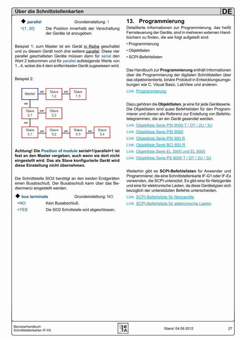
27BenutzerhandbuchSchnittstellenkarten IF-XX
DE
Stand: 04.09.2012
parallel Grundeinstellung: 1=1..30 Die Position innerhalb der Verschaltung
der Geräte ist anzugeben.
Beispiel 1: zum Master ist ein Gerät in Reihe geschaltet und zu diesem Gerät noch drei weitere parallel. Diese vier parallel geschalteten Geräte müssen dann für serial den Wert 2 bekommen und für parallel aufsteigende Werte von 1...4, wobei die 4 dem entferntesten Gerät zugewiesen wird.
Beispiel 2:
Achtung! Die Position of module serial=1/parallel=1 ist fest an den Master vergeben, auch wenn sie dort nicht eingestellt wird. Das als Slave konfigurierte Gerät wird diese Einstellung nicht übernehmen.
Die Schnittstelle SIO2 benötigt an den beiden Endgeräten einen Busabschluß. Der Busabschluß kann über das Be-dienmenü eingestellt werden.
bus terminate Grundeinstellung: NO =NO Kein Busabschluß. =YES Die SIO2 Schnittstelle wird abgeschlossen.
Über die Schnittstellenkarten
13. ProgrammierungDetaillierte Informationen zur Programmierung, das heißt Fernsteuerung der Geräte, sind in mehreren externen Hand-büchern zu finden, die wie folgt aufgeteilt sind:• Programmierung• Objektlisten• SCPI-Befehlslisten
Das Handbuch zur Programmierung enthält Informationen über die Programmierung der digitalen Schnittstellen über das objektorientierte, binäre Protokoll in Entwicklungsumge-bungen wie C, Visual Basic, LabView und anderen. Link: Programmierung
Dazu gehören die Objektlisten, je eine für jede Geräteserie. Die Objektlisten sind quasi Befehlslisten für den Program-mierer und dienen als Referenz zur Erstellung von Befehls-telegrammen, die an ein Gerät gesendet werden.Link: Objektliste Serie PSI 8000 T / DT / 2U / 3ULink: Objektliste Serie PSI 9000Link: Objektliste Serie PSI 800 RLink: Objektliste Serie BCI 800 RLink: Objektliste Serie EL 3000 und EL 9000Link: Objektliste Serie PS 8000 T / DT / 2U / 3U
Weiterhin gibt es SCPI-Befehlslisten für Anwender und Programmierer, die eine Schnittstellenkarte IF-G1 oder IF-Ex verwenden, die SCPI untersützt. Es gibt eine für Netzgeräte und eine für elektronische Lasten, da diese Gerätetypen sich bezüglich der unterstützten Befehle unterscheiden.Link: SCPI-Befehlsliste für NetzgeräteLink: SCPI-Befehlsliste für elektronische Lasten
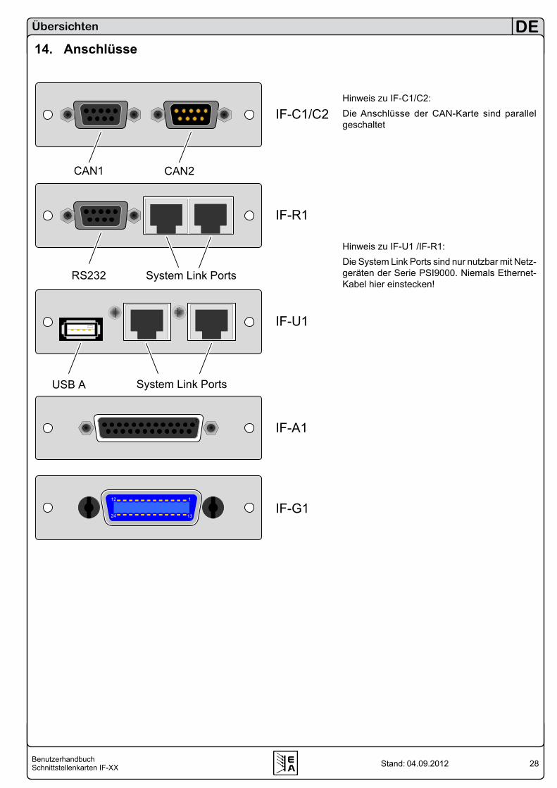
28BenutzerhandbuchSchnittstellenkarten IF-XX
DE
Stand: 04.09.2012
Übersichten
14. Anschlüsse
Hinweis zu IF-C1/C2:Die Anschlüsse der CAN-Karte sind parallel geschaltet
Hinweis zu IF-U1 /IF-R1:Die System Link Ports sind nur nutzbar mit Netz-geräten der Serie PSI9000. Niemals Ethernet-Kabel hier einstecken!
CAN1 CAN2
RS232 System Link Ports
System Link PortsUSB A
IF-C1/C2
IF-R1
IF-A1
IF-G1
IF-U1
1
112
1324

29BenutzerhandbuchSchnittstellenkarten IF-XX
DE
Stand: 04.09.2012
Übersichten
LAN USB AReset
USB A
USB A ProfibusStatus
IF-E1BIF-E2
IF-R2
IF-U2
IF-PB1


31User ManualInterface cards IF-XX
EN
Date: 04-09-2012
Important!• Only equip the interface card(s) in units which are designed
to be used with them! It is not required to open the unit. Information about which devices are capable of running these interface cards can be requested from your local dealer or read in the user manual of the devices.
• Only equip the interface card(s) while the unit is switched off by the mains switch!
• Units featuring two slots might be equipped with two cards, but you can’t combine them arbitrarily. For detailed infor-mation see section „3.3 Combining interface cards“
• Never remove the covers from the cards! • If only one card is equipped in units with two slots it is
recommended to install the default slot cover to the open slot. This protects the unit from additional dust pollution and ensures correct air circulation with the internal fans.
• Use and follow the common ESD provisions when installing and removing the interface cards!
About & CopyrightElektro-Automatik GmbH & Co. KGHelmholtzstrasse 31-3341747 ViersenGermanyPhone: +49 2162 / 37850Fax: +49 2162 / 16230Web: www.elektroautomatik.deMail: [email protected]
© Elektro-AutomatikReprint, duplication or partly, wrong use of this user manual are prohibited and might be followed by legal consequences.
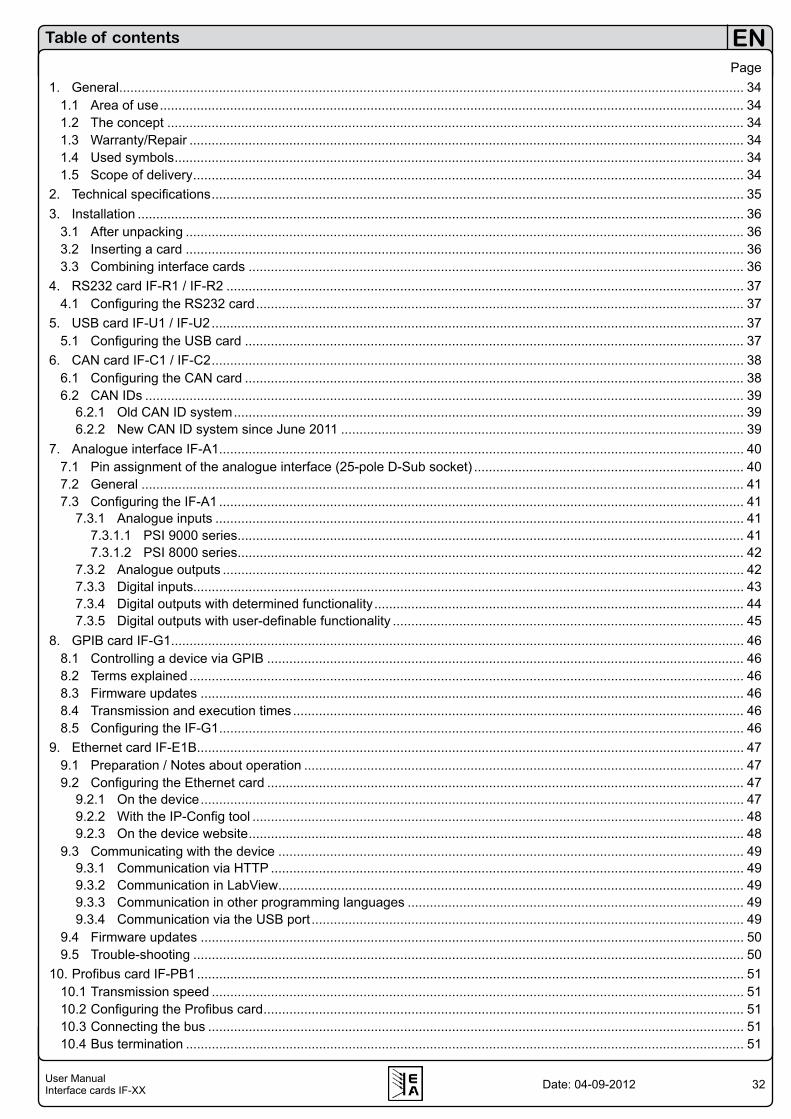
32User ManualInterface cards IF-XX
EN
Date: 04-09-2012
Page1. General ......................................................................................................................................................................... 34
1.1 Area of use .............................................................................................................................................................. 341.2 The concept ............................................................................................................................................................ 341.3 Warranty/Repair ...................................................................................................................................................... 341.4 Used symbols .......................................................................................................................................................... 341.5 Scope of delivery ..................................................................................................................................................... 34
2. Technical specifications ................................................................................................................................................ 353. Installation .................................................................................................................................................................... 36
3.1 After unpacking ....................................................................................................................................................... 363.2 Inserting a card ....................................................................................................................................................... 363.3 Combining interface cards ...................................................................................................................................... 36
4. RS232 card IF-R1 / IF-R2 ............................................................................................................................................ 374.1 Configuring the RS232 card .................................................................................................................................... 37
5. USB card IF-U1 / IF-U2 ................................................................................................................................................ 375.1 Configuring the USB card ....................................................................................................................................... 37
6. CAN card IF-C1 / IF-C2 ................................................................................................................................................ 386.1 Configuring the CAN card ....................................................................................................................................... 386.2 CAN IDs .................................................................................................................................................................. 39
6.2.1 Old CAN ID system .......................................................................................................................................... 396.2.2 New CAN ID system since June 2011 ............................................................................................................. 39
7. Analogue interface IF-A1 .............................................................................................................................................. 407.1 Pin assignment of the analogue interface (25-pole D-Sub socket) ......................................................................... 407.2 General ................................................................................................................................................................... 417.3 Configuring the IF-A1 .............................................................................................................................................. 41
7.3.1 Analogue inputs ............................................................................................................................................... 417.3.1.1 PSI 9000 series ......................................................................................................................................... 417.3.1.2 PSI 8000 series ......................................................................................................................................... 42
7.3.2 Analogue outputs ............................................................................................................................................. 427.3.3 Digital inputs..................................................................................................................................................... 437.3.4 Digital outputs with determined functionality .................................................................................................... 447.3.5 Digital outputs with user-definable functionality ............................................................................................... 45
8. GPIB card IF-G1 ........................................................................................................................................................... 468.1 Controlling a device via GPIB ................................................................................................................................. 468.2 Terms explained ...................................................................................................................................................... 468.3 Firmware updates ................................................................................................................................................... 468.4 Transmission and execution times .......................................................................................................................... 468.5 Configuring the IF-G1 .............................................................................................................................................. 46
9. Ethernet card IF-E1B .................................................................................................................................................... 479.1 Preparation / Notes about operation ....................................................................................................................... 479.2 Configuring the Ethernet card ................................................................................................................................. 47
9.2.1 On the device ................................................................................................................................................... 479.2.2 With the IP-Config tool ..................................................................................................................................... 489.2.3 On the device website ...................................................................................................................................... 48
9.3 Communicating with the device .............................................................................................................................. 499.3.1 Communication via HTTP ................................................................................................................................ 499.3.2 Communication in LabView .............................................................................................................................. 499.3.3 Communication in other programming languages ........................................................................................... 499.3.4 Communication via the USB port ..................................................................................................................... 49
9.4 Firmware updates ................................................................................................................................................... 509.5 Trouble-shooting ..................................................................................................................................................... 50
10. Profibus card IF-PB1 .................................................................................................................................................... 5110.1 Transmission speed ................................................................................................................................................ 5110.2 Configuring the Profibus card .................................................................................................................................. 5110.3 Connecting the bus ................................................................................................................................................. 5110.4 Bus termination ....................................................................................................................................................... 51
Table of contents
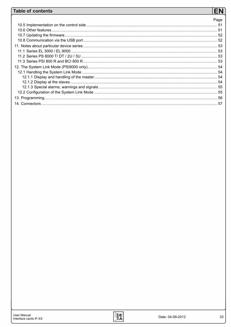
33User ManualInterface cards IF-XX
EN
Date: 04-09-2012
Table of contents
Page10.5 Implementation on the control side ......................................................................................................................... 5110.6 Other features ......................................................................................................................................................... 5110.7 Updating the firmware ............................................................................................................................................. 5210.8 Communication via the USB port ............................................................................................................................ 52
11. Notes about particular device series ............................................................................................................................ 5311.1 Series EL 3000 / EL 9000 ....................................................................................................................................... 5311.2 Series PS 8000 T/ DT / 2U / 3U .............................................................................................................................. 5311.3 Series PSI 800 R and BCI 800 R ............................................................................................................................ 53
12. The System Link Mode (PSI9000 only) ........................................................................................................................ 5412.1 Handling the System Link Mode ............................................................................................................................. 54
12.1.1 Display and handling of the master .................................................................................................................. 5412.1.2 Display at the slaves ........................................................................................................................................ 5412.1.3 Special alarms, warnings and signals .............................................................................................................. 55
12.2 Configuration of the System Link Mode .................................................................................................................. 5513. Programming ................................................................................................................................................................ 5614. Connectors ................................................................................................................................................................... 57

34User ManualInterface cards IF-XX
EN
Date: 04-09-2012
About the interface cards
1. GeneralThe interface cards IF-Rx (RS232), IF-Cx (CAN), IF-Ux (USB), IF-G1 (GPIB), IF-Ex (Ethernet) and IF-PB1 (Profibus) provide a digital and the IF-A1 an analogue connection to a control unit like a PC or PLC. Devices like, for example, a power supply can be monitored and controlled. Basic software for power supplies and electronic loads, for the use with some of these interface cards, is supplied with the included tools CD.The models IF-U2, IF-R2, IF-C2 and IF-E2 are reduced ver-sions of the -1 types and may only be used in certain series.The 25 pole, analogue interface card IF-A1 (supported by series PSI 9000 and PSI 8000) allows fast monitoring of actual values and fast setting (with a very short delay) of set values, all within the nominal values of the device. The digital inputs and outputs are parameterisable.PSI 9000 series only: with the combination of a RS232 or USB card and a CAN card, the user can realise a gateway from the RS232 or USB port of a PC to a CAN bus. Thus no extra hardware is required to connect the PC to CAN. The gateway allows to control up to 30 units in line by the RS232/USB and CAN cards. The device that is connected to the PC will handle the data conversion to CAN and back. The maximum data transmission speed is then limited to what the serial connection has been set to. Total maximum baud rate is 57600 baud.PSI 9000 series only: the cards IF-R1 and IF-U1 additionally support the parallel and/or series connection of multiple la-boratory power supplies to a true master-slave system with totals formation of the measured values by using the „System Link mode“. Also see user guide of PSI 9000 and section „12. The System Link Mode (PSI9000 only)“.
1.1 Area of useThe interface cards must only be equipped in units which are designed for them. A set of Labview VIs is included in the package, which will simplify the use and implementation of the interface cards in the LabView IDE.The implementation in other applications and environments is possible, but also very complex. The telegram structure is explained in detail in seperate documents, available on the included CD in folder „\manuals\interface cards\“ or on our web site (ZIP file with instruction manuals for all interface cards).The voltage range of the analogue input and output signals of the IF-A1 is customisable between 0 and 10V. The digital inputs can be switched between two different voltage ranges for the logical level and the default logical level can be pre-defined for the case that these inputs are not used.
1.2 The conceptThe interface cards are pluggable and can thus be used where needed. They are compatible to various types of de-vices, such as electronic loads. Due to the electrical isolation of 2000V (with Profibus card: 1000V) you can also connect multiple devices with different potentials.The USB, RS232 and CAN interfaces support a unique communication protocol, which is object orientated. Every series has its dedicated object (ie. command) list, which differs depending on the features of a model. Transmitted commands are checked for validity and plausibility. Non-plausible or erroneous values and objects result in an error which is sent as an answer telegram.The digital cards IF-G1 and IF-Ex use the standardised command language SCPI (Standard Commands for Pro-grammable Intruments). Interface IF-PB1 follows the Profibus specification. Refer to section „13. Programming“ for an overview about furtherly available documentation.
1.3 Warranty/RepairAttention: The interface card must not be repaired by the user!In case of warranty or a defect please contact your supplier to get informed about the next steps. The cards are conceded with a statutory warranty of two years (for Germany), which is independent from the warranty (and its duration) of the device they are used in.
1.4 Used symbolsIn the following description the display and operating ele-ments are marked differently by symbols.
= Displayed only, all elements which are only dis-played and which represent a state are marked with this symbol
= Parameter, changeable values, are marked with this symbol and are emphasised
= Menu items, selectable, lead to the next sublevel or to the bottom level with parametersBrackets … mark possible options or adjustment ranges for parameters.
1.5 Scope of delivery1 x Pluggable interface card1 x CD with software, instruction manuals and more1 x Short installation guide1 x Patch cable 0.5m 1:1 (only with IF-R1 and IF-U1)1 x USB cable A-A, 1.8m (only with IF-Ux, IF-Ex, IF-PB1 )1 x RS232 cable 1:1, 3m (only with IF-Rx)1 x Adapter cable for firmware updates (only with IF-G1)
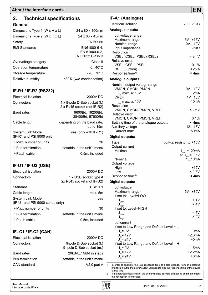
35User ManualInterface cards IF-XX
EN
Date: 04-09-2012
2. Technical specificationsGeneralDimensions Type 1 (W x H x L) 24 x 80 x 100mmDimensions Type 2 (W x H x L) 24 x 80 x 45mmSafety EN 60950EMI Standards EN61000-6-4, EN 61000-6-2, EN 55022 Class BOvervoltage category Class IIOperation temperature 0...40°CStorage temperature -20...70°CRelative humidity <80% (w/o condensation)
IF-R1 / IF-R2 (RS232)Electrical isolation 2000V DCConnectors 1 x 9-pole D-Sub socket (f.) 2 x RJ45 socket (not IF-R2)Baud rates 9600Bd, 19200Bd, 38400Bd, 57600BdCable length depending on the baud rate, up to 15mSystem Link Mode yes (only with IF-R1) (IF-R1 and PSI 9000 only) Max. number of units 30 Bus termination settable in the unit’s menu Patch cable 0.5m, included
IF-U1 / IF-U2 (USB)Electrical isolation 2000V DCConnectors 1 x USB socket type A 2x RJ45 socket (not IF-U2)Standard USB 1.1Cable length max. 5mSystem Link Mode yes (IF-U1 and PSI 9000 series only) Max. number of units 30 Bus termination settable in the unit’s menu Patch cable 0.5m, included
IF- C1 / IF-C2 (CAN)Electrical isolation 2000V DCConnectors 9-pole D-Sub socket (f.) 9- pole D-Sub socket (m.)Baud rates 20kBd...1MBd in stepsBus termination settable in the unit’s menuCAN standard V2.0 part A
About the interface cards
IF-A1 (Analogue)Electrical isolation 2000V DCAnalogue inputs: Input voltage range Maximum range -5V...+15V Nominal range 0V…10V Input impedance 25kΩ Resolution VSEL, CSEL, PSEL (RSEL) < 2mV Relative error VSEL, CSEL, PSEL 0.1% RSEL (Option) 0.25% Response time1) < 4msAnalogue outputs: Nominal output voltage range VMON, CMON, PMON 0V…10V Iout max. at 10V 2mA VREF 1V...10V Iout max. at 10V 10mA Resolution VMON, CMON, PMON, VREF < 2mV Relative error VMON, CMON, PMON, VREF 0.1% Settling time of the analogue outputs < 4ms Auxiliary voltage 12…15V Current max. 50mADigital outputs: Typ e pull-up resistor to +15V Output current Maximal Imax = -20mA at Uout = 0.5V Nominal 1...10mA Output voltage High +15V Low < 0.3V Response time2) < 4msDigital outputs: Input voltage Maximum range -5V...+30V if set to: Level=LOW ULow < 1V UHigh > 4V if set to: Level=HIGH ULow < 5V UHigh > 9V Input current if set to Low Range and Default Level = L Uin= 0V 0mA Uin= 12V +2.6mA Uin= 24V +5mA if set to Low Range and Default Level = H Uin= 0V -1.5mA Uin= 12V +2.2mA Uin= 24V +6mA
1 In order to calculate the total response time of a step change, from an analogue interface input to the power output you need to add the response time of the device to this time.
2 Time between occurence of the event which is going to be notified and the moment the notification is executed.

36User ManualInterface cards IF-XX
EN
Date: 04-09-2012
About the interface cards
if set to High Range and Default Level = L Uin= 0V 0mA Uin= 12V +1.6mA Uin= 24V +3.5mA if set to High Range and Default Level = H Uin= 0V -1.5mA Uin= 12V +0.7mA Uin= 24V +4.5mA Response time1) < 10ms
IF- G1 (GPIB)Electrical isolation 2000V DCTerminals 24pole Centronics socket (female)Bus standard IEEE 488.1/2Cable length (GPIB) 2m per device, 20m totalCable type (GPIB) Standard GPIB cable
IF-E1 / IF-E1B (Ethernet)Electrical isolation 1500V DCTerminals 1x RJ45 (LAN / WAN) 1x USB, type ACable type (Ethernet) Twisted pair, patch cable, Cat 3 or higherProtocols HTTP, TCP/IPNetwork ports IF-E1B 0 - 65535 (80=HTTP) Default: 1001 (TCP/IP)Netzwork ports IF-E1 80 (HTTP, TCP/IP)Network connection 10/100 MBitUSB connection USB 1.1, 2.0Transmission speed Ethernet 100 kBaudTransmission speed USB 57600 BaudCommand interval max. every 300ms (IF-E2) every 20ms (IF-E1B)Keep-alive timeout (IF-E1B) 10min. (since v2.05)
IF-PB1 (Profibus)Electrical isolation 1000V DCTerminals 1x Sub-D 9pole 1x USB, type AVariant DPBus termination via Profibus cableBus speed up to 12MBit/sProtocols DPV0, DPV1Identification with GSE file
1 Time between occurance of an event, that has to be signalised to an output, and the moment it is signalised.
3. Installation3.1 After unpackingAfter unpacking, check the pluggable interface card(s) for signs of physical damage. If any damage can be found do not use and insert the card into any device!
3.2 Inserting a cardThe card(s) must only be inserted while the unit is completely switched off. The unit does not have to be opened. Remove the screws from the slot cover or from an already equipped card and remove the cover/card. Insert the new card with caution until the card plate touches the rear side of the unit. If there is space between the rear side and the card pla-te, do not tighten the screws, because the card is not placed correctly! The wiring between the PC and/or other units has also be done before the unit is switched on again. The card(s) will be automatically detected by the device after powering it on and can now be configured. Note about the IF-A1: before equipping the card, you should set the jumpers correctly. Refer to „7.3 Configuring the IF-A1“, subsection „Digital inputs“.Note: in case the card was purchased subsequently and is not recognized by the device, it might be necessary to update the firmware of the device. Please contact your dealer for further information.Caution! There are components on the card which are sen-sitive for ESD. You must follow the general ESD provi-sions when handling and installing a card.
3.3 Combining interface cardsOnly applies for series PSI 9000!In case more than one card slot is used, the table shows which cards can be combined (• means allowed):
IF-U1 IF-C1 IF-R1 IF-E1 /IF-E1B IF-G1 IF-A1 IF-PB1
IF-U1 - • - - • - -IF-C1 • - • - - • •IF-R1 - • - - • - -IF-E1 /IF-E1B - - - - - - -IF-G1 • - • - - • •IF-A1 - • - - • - -IF-PB1 - • - - • - -
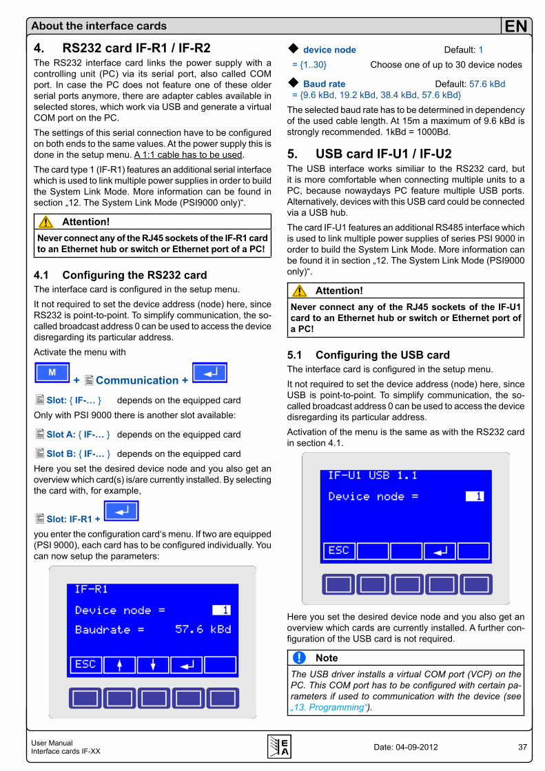
37User ManualInterface cards IF-XX
EN
Date: 04-09-2012
4. RS232 card IF-R1 / IF-R2The RS232 interface card links the power supply with a controlling unit (PC) via its serial port, also called COM port. In case the PC does not feature one of these older serial ports anymore, there are adapter cables available in selected stores, which work via USB and generate a virtual COM port on the PC.The settings of this serial connection have to be configured on both ends to the same values. At the power supply this is done in the setup menu. A 1:1 cable has to be used.The card type 1 (IF-R1) features an additional serial interface which is used to link multiple power supplies in order to build the System Link Mode. More information can be found in section „12. The System Link Mode (PSI9000 only)“.
Attention!Never connect any of the RJ45 sockets of the IF-R1 card to an Ethernet hub or switch or Ethernet port of a PC!
4.1 Configuring the RS232 cardThe interface card is configured in the setup menu.It not required to set the device address (node) here, since RS232 is point-to-point. To simplify communication, the so-called broadcast address 0 can be used to access the device disregarding its particular address.Activate the menu with
M + Communication +
Slot: IF-… depends on the equipped cardOnly with PSI 9000 there is another slot available:
Slot A: IF-… depends on the equipped card
Slot B: IF-… depends on the equipped cardHere you set the desired device node and you also get an overview which card(s) is/are currently installed. By selecting the card with, for example,
Slot: IF-R1 + you enter the configuration card‘s menu. If two are equipped (PSI 9000), each card has to be configured individually. You can now setup the parameters:
device node Default: 1 = 1..30 Choose one of up to 30 device nodes
Baud rate Default: 57.6 kBd = 9.6 kBd, 19.2 kBd, 38.4 kBd, 57.6 kBdThe selected baud rate has to be determined in dependency of the used cable length. At 15m a maximum of 9.6 kBd is strongly recommended. 1kBd = 1000Bd.
5. USB card IF-U1 / IF-U2The USB interface works similiar to the RS232 card, but it is more comfortable when connecting multiple units to a PC, because nowaydays PC feature multiple USB ports. Alternatively, devices with this USB card could be connected via a USB hub. The card IF-U1 features an additional RS485 interface which is used to link multiple power supplies of series PSI 9000 in order to build the System Link Mode. More information can be found it in section „12. The System Link Mode (PSI9000 only)“.
Attention!Never connect any of the RJ45 sockets of the IF-U1 card to an Ethernet hub or switch or Ethernet port of a PC!
5.1 Configuring the USB cardThe interface card is configured in the setup menu.It not required to set the device address (node) here, since USB is point-to-point. To simplify communication, the so-called broadcast address 0 can be used to access the device disregarding its particular address.Activation of the menu is the same as with the RS232 card in section 4.1.
Here you set the desired device node and you also get an overview which cards are currently installed. A further con-figuration of the USB card is not required.
NoteThe USB driver installs a virtual COM port (VCP) on the PC. This COM port has to be configured with certain pa-rameters if used to communication with the device (see „13. Programming“).
About the interface cards

38User ManualInterface cards IF-XX
EN
Date: 04-09-2012
About the interface cards
6. CAN card IF-C1 / IF-C2CAN Standard: V2.0 part ACable length: depending on the baud rateThe communication over the CAN bus is specifically desi-gned to suit the needs of test applications and systems, like for instance in the automotive industry. A subsequent imple-mentation into existing systems and the modification of a related software application is possible and unproblematic.The networking of CAN devices provides the advantage of a faster communication and a fail-safe bus topology. The driver chip on the CAN card can support up to 110 device nodes (the term „device node“ is used for CAN bus members). The communication protocol can handle up to 30 units per address segment (RID). Thus it is theoretically possible to set up a bus system of up to 110 units, which will operate with at least 4 address segments. The address segments are relocatable, so that the one or multiple devices can be implemented into an existing CAN bus without the need to reconfigure the whole system.
6.1 Configuring the CAN cardThe interface card is configured in the setup menu.Since June, 2011 there is a new CAN ID system that will is going to replace the old ID system. This is just done with a software update of the device, the hardware is not effected. You can recognize which of the CAN ID systems currently is implemented in the device by the available setup menu items.By selecting the card with
Slot: IF-C1 + you enter the configuration menu for that particular card. Each card has to be configured individually. You can now setup some parameters.
Figure shows IF-C1 settings of the „old“ CAN-ID system, see below
Setting the baud rateAll common baud rates between 10kBd and 1MBd are supported. Only with PSI 9000 models, for each baud rate setting the so-called „Sample point“ can be chosen, which is used to optimise the data transmission for various cable lengths and qualities. It adjusts the point of time when a transmitted bit is sampled.
baudrate Default: 100 kBd sample point: 75% (only available with series PSI 9000) = 10 kBd 60, 65, 70, 75, 80, 85%, 20 kBd 60, 65, 70, 75, 80, 85 %, 50 kBd 60, 65, 70, 75, 80, 85 %, 100 kBd 60, 65, 70, 75, 80, 85 %, 125 kBd 58, 68, 70, 75, 81, 87 %, 250 kBd 58, 68, 70, 75, 81, 87 %, 500 kBd 58, 66, 75, 83 %, 1 MBd 58, 66, 75, 83 %
Bus terminationThe CAN bus requires a termination resistor of 120 Ohms on both ends of the line. If a unit is located at the end of the chain/line and it is not connected to a next unit, it has to be terminated. The parameter „bus terminate“ is used to easily set the termination without any circumstancial hardware termination by jumpers.
bus terminate Default: NO =YES The bus is terminated with a 120Ω resistor. =NO No termination is done.
Gateway function (only PSI9000)
CAN Default: Client =Client The device is monitored and controlled by an
external unit, like a PC or a SPS =Gateway The interface card additionally serves as a
gateway between the CAN and RS232/USB cards
The RS232 or USB card inside the device which is assi-gned as the gateway (here: PSI 9000) allows the user to control and monitor all further units, which are linked to that particular device by CAN. All that is needed is a device with an extra IF-R1 or IF-U1 interface card to set up a CAN bus system. Both cards, RS232 and USB, can only utilise the high performance of the CAN bus very poorly. In order to use the CAN bus with full performance (high data rate) and many devices, it is recommended to directly control the bus with a CAN master hardware.

39User ManualInterface cards IF-XX
EN
Date: 04-09-2012
6.2 CAN IDs
6.2.1 Old CAN ID systemIt is absolutely necessary to choose and set a unique device address, also called „device node“, for every connected or linked unit. Only then a unit can be identified and controlled correctly. These identifiers are used to access a unit.
Relocating address segmentsIn case that devices are retrofitted with a CAN card and implemented into an existing CAN bus system, the „reloca-table identifier segment“ (short: RID) is used to relocate the address segment in order to adapt the addresses of the new unit(s) to the address range of the already exisiting units or to set it away from that range to not collide.The CAN bus after the standard V2.0a defines an 11 bits long address (=identifier). This results in a total of 2048 identifiers, while from 2032 can be chosen. Those 2048 identifiers are seperated into 32 address segments of 64 addresses. The starting address is determined by the RID.
relocatable ID Default: 0 segment = 0..31 Select (relocate) the address rangeInside of every address segment are 62 freely assignable addresses, whereas the up to 30 units are using the lower range and with 2 physical adresses (identifiers, one each for sending and querying data) per unit they are taking the addresses from 2...61. The addresses 0 and 1 of every address range are reserved for broadcast messages. This results in 32*2 broadcast addresses.For broadcast messages the addresses are static:[RID*64 + 0] and [RID*64 + 1].Example: the RID is set to 5 (also see setup menu of your device). A broadcast shall be sent to all units of this address range. The identifier hence calculates as 5*64 = 320 = 0x140, or 0x141 for queries.For singlecast messages every „device node“ is occupy-ing another two addresses: [RID*64 + device node * 2] and[RID*64 + device node * 2 + 1]Example: the RID was set to 13, the device address (node) to 12. In order to control the device, the identifier has to be: 13*64 + 12*2 = 856 (0x358). The identifier 857 (0x359) is used for queries.
About the interface cards
6.2.2 New CAN ID system since June 2011The new CAN ID system is first available for PS 8000 and EL3000/EL9000 series, other series like PSI 8000 follow. Further series upon request.For this system, it is required to set a base CAN ID. This will determine the three CAN IDs which are used by the device. The other ID, the broadcast ID, can be ignored if unused and not colliding with the standard IDs.For the settings for a PS 8000 power supply model please refer to the instruction manual of the device.For a PSI 8000 model, the CAN setup will look like this:
Base ID Default: 0x000The base ID is adjusted as hexadecimal value in steps of 4. The device will then use three normal CAN IDs: base ID, base ID + 1 and base ID + 2. This system is compatible to Vector software like CANoe or CANalyzer. Databases in *.dbc format are available either directly on the CD that comes with the interface card or upon request. For every device model, a unique database is required. Demo configurations for testing purposes that can be loaded into CANoe or CANalyzer will also be available.
Broadcast ID Default: 0x7FFThis adjusts the so-called broadcast ID as hexdecimal value. This ID must not collide with one of the other IDs of the unit.The purpose of the broadcast ID is to adjust it to the same value on several units on the same bus in order to send command to all units at once. This might be required when setting a current or the output condition simultaneously on these units.This ID can only be used to send set values or condition, not to query status or similar.The other settings are like described in section 6.2.1.
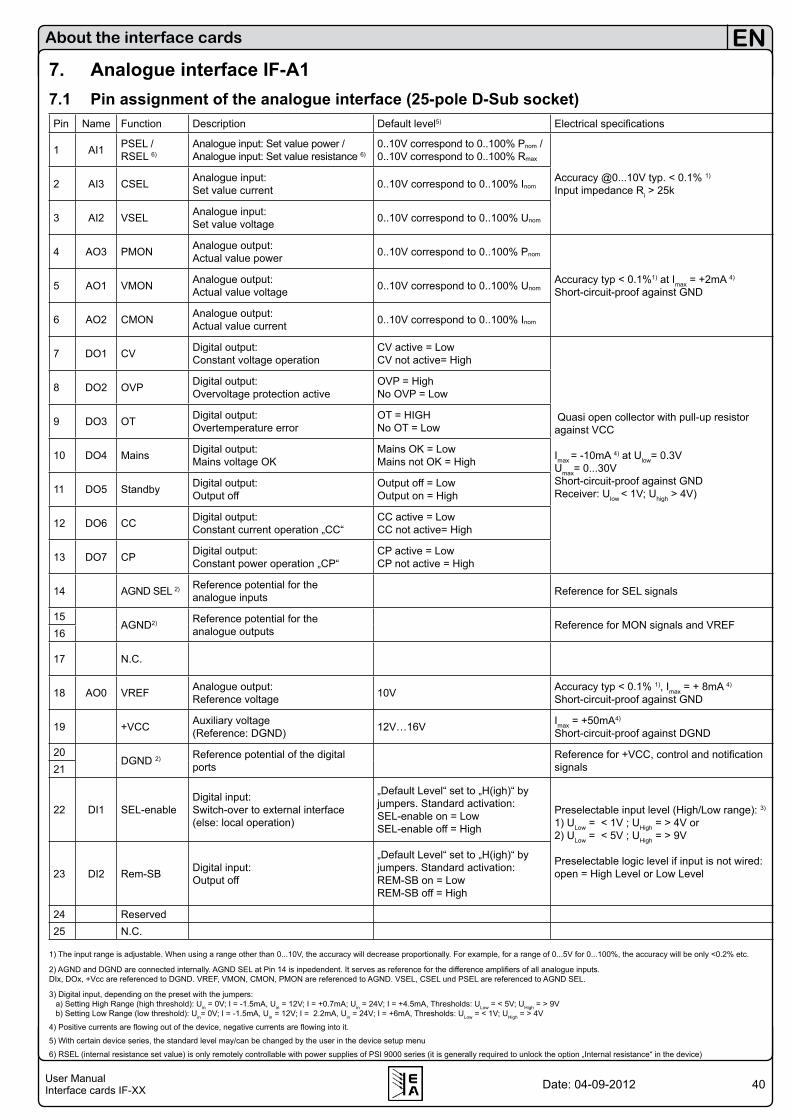
40User ManualInterface cards IF-XX
EN
Date: 04-09-2012
About the interface cards
7. Analogue interface IF-A17.1 Pin assignment of the analogue interface (25-pole D-Sub socket)Pin Name Function Description Default level5) Electrical specifications
1 AI1 PSEL /RSEL 6)
Analogue input: Set value power /Analogue input: Set value resistance 6)
0..10V correspond to 0..100% Pnom /0..10V correspond to 0..100% Rmax
Accuracy @0...10V typ. < 0.1% 1)
Input impedance Ri > 25k2 AI3 CSEL Analogue input: Set value current 0..10V correspond to 0..100% Inom
3 AI2 VSEL Analogue input: Set value voltage 0..10V correspond to 0..100% Unom
4 AO3 PMON Analogue output: Actual value power 0..10V correspond to 0..100% Pnom
Accuracy typ < 0.1%1) at Imax = +2mA 4)
Short-circuit-proof against GND5 AO1 VMON Analogue output: Actual value voltage 0..10V correspond to 0..100% Unom
6 AO2 CMON Analogue output: Actual value current 0..10V correspond to 0..100% Inom
7 DO1 CV Digital output: Constant voltage operation
CV active = Low CV not active= High
Quasi open collector with pull-up resistor against VCC
Imax = -10mA 4) at Ulow= 0.3VUmax= 0...30VShort-circuit-proof against GND Receiver: Ulow < 1V; Uhigh > 4V)
8 DO2 OVP Digital output: Overvoltage protection active
OVP = High No OVP = Low
9 DO3 OT Digital output: Overtemperature error
OT = HIGH No OT = Low
10 DO4 Mains Digital output: Mains voltage OK
Mains OK = Low Mains not OK = High
11 DO5 Standby Digital output: Output off
Output off = Low Output on = High
12 DO6 CC Digital output: Constant current operation „CC“
CC active = Low CC not active= High
13 DO7 CP Digital output: Constant power operation „CP“
CP active = Low CP not active = High
14 AGND SEL 2) Reference potential for the analogue inputs Reference for SEL signals
15AGND2) Reference potential for the
analogue outputs Reference for MON signals and VREF16
17 N.C.
18 AO0 VREF Analogue output: Reference voltage 10V Accuracy typ < 0.1% 1), Imax = + 8mA 4)
Short-circuit-proof against GND
19 +VCC Auxiliary voltage (Reference: DGND) 12V…16V Imax = +50mA4)
Short-circuit-proof against DGND
20DGND 2) Reference potential of the digital
portsReference for +VCC, control and notification signals21
22 DI1 SEL-enableDigital input:Switch-over to external interface (else: local operation)
„Default Level“ set to „H(igh)“ by jumpers. Standard activation:SEL-enable on = LowSEL-enable off = High
Preselectable input level (High/Low range): 3)
1) ULow = < 1V ; UHigh = > 4V or2) ULow = < 5V ; UHigh = > 9V
Preselectable logic level if input is not wired:open = High Level or Low Level23 DI2 Rem-SB Digital input:
Output off
„Default Level“ set to „H(igh)“ by jumpers. Standard activation:REM-SB on = LowREM-SB off = High
24 Reserved25 N.C.
1) The input range is adjustable. When using a range other than 0...10V, the accuracy will decrease proportionally. For example, for a range of 0...5V for 0...100%, the accuracy will be only <0.2% etc.
2) AGND and DGND are connected internally. AGND SEL at Pin 14 is inpedendent. It serves as reference for the difference amplifiers of all analogue inputs. DIx, DOx, +Vcc are referenced to DGND. VREF, VMON, CMON, PMON are referenced to AGND. VSEL, CSEL und PSEL are referenced to AGND SEL.
3) Digital input, depending on the preset with the jumpers: a) Setting High Range (high threshold): Uin = 0V; I = -1.5mA, Uin = 12V; I = +0.7mA; Uin = 24V; I = +4.5mA, Thresholds: ULow = < 5V; UHigh = > 9V b) Setting Low Range (low threshold): Uin= 0V; I = -1.5mA, Uin = 12V; I = 2.2mA, Uin = 24V; I = +6mA, Thresholds: ULow = < 1V; UHigh = > 4V
4) Positive currents are flowing out of the device, negative currents are flowing into it.
5) With certain device series, the standard level may/can be changed by the user in the device setup menu
6) RSEL (internal resistance set value) is only remotely controllable with power supplies of PSI 9000 series (it is generally required to unlock the option „Internal resistance“ in the device)

41User ManualInterface cards IF-XX
EN
Date: 04-09-2012
About the interface cards
7.2 GeneralThe interface IF-A1 is an analogue interface with galvani-cally isolated, customisable, analogue and digital inputs and outputs. Visualisation:
IF-A1
NetzgeräteseitePSU side
Ein/AusgängeIn/Out
Customisable means, that you can customise these inputs and outputs to your needs, but always within a voltage ran-ge of 0...10V. At devices with two extension card slots (eg. PSI9000) it is possible to combine the IF-A1 with a digital interface card (eg. IF-U1 (USB)), in order to control, for example, the device by USB and put out actual values via the analogue outputs of the analogue card. Or vice versa, you control the device by analogue set values and read out and log the actual values to a PC via RS232, CAN or USB.It applies generally: all monitoring and surveillance features are permanently active, even if two cards (one digital, one analogue) are equipped. Only the control of the device with set values requires the activation of the external mode (IF-A1) resp. of the remote mode (digital interfaces), whereas the remote mode has priority. In case the device is in control by an analogue interface (external mode, indicated in the display by extern) and the control of the device via a digital interface is activated, the device will switch to remote mode (indicated in the display by remote).
7.3 Configuring the IF-A1The interface is configured in the communication menu:
With M
+ Communication + and
Slot A|B: IF-A1 + the analogue interface card is selected for configuration. Following parameters can be set:
7.3.1 Analogue inputsAnalogue set values are only accepted by the device if it is in external mode (indicated in the display by extern). Access to the menu is blocked in external mode.The analogue interface IF-A1 has three analogue inputs with these functions:
AI1: PSEL (external set value for power) AI3: CSEL (external set value for current)AI2: VSEL (external set value for voltage)The nominal voltage range of these inputs is 0...10V, but it can be narrowed in order to adapt to the input signal. By limitting the standard voltage range to a lower one the reso-lution is also lowered. Example: if the voltage range is set to only 1V difference, resolution and accuracy will be reduced by the factor 10. The left value defines the input voltage for 0% output value (U, I, P), the right value the input voltage for 100% output value. The menu differs a little between the various series:
7.3.1.1 PSI 9000 seriesIt applies:Umin (left value) = 0.00V...4.00V Umax (right value) = 5.00V...10.00V A higher or lower voltage than specified is clipped and treated as either 0% or 100%.Menu items:Nom.value | Adj.limits Default: Nom.value = Nom.value the defined range for VSEL, CSEL and PSEL is always related to the nominal values of the device (see explanations below) = Adj.limits the range for VSEL, CSEL and PSEL is always related to the adjustment limits of the device (see explanations below)
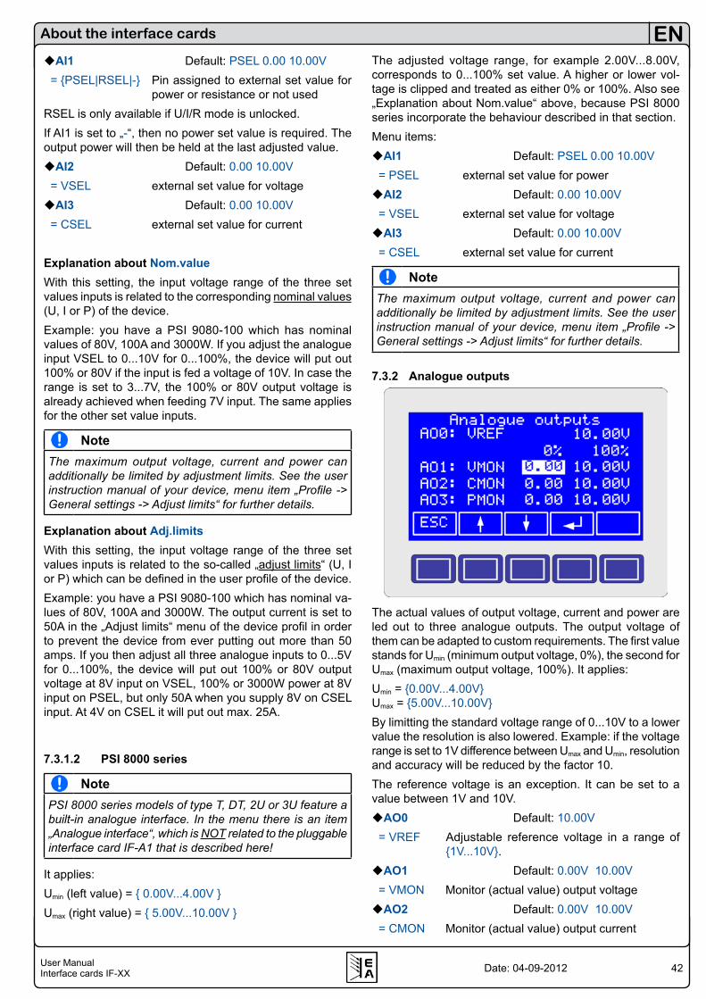
42User ManualInterface cards IF-XX
EN
Date: 04-09-2012
AI1 Default: PSEL 0.00 10.00V = PSEL|RSEL|- Pin assigned to external set value for power or resistance or not usedRSEL is only available if U/I/R mode is unlocked.If AI1 is set to „-“, then no power set value is required. The output power will then be held at the last adjusted value.AI2 Default: 0.00 10.00V = VSEL external set value for voltageAI3 Default: 0.00 10.00V = CSEL external set value for current
Explanation about Nom.valueWith this setting, the input voltage range of the three set values inputs is related to the corresponding nominal values (U, I or P) of the device. Example: you have a PSI 9080-100 which has nominal values of 80V, 100A and 3000W. If you adjust the analogue input VSEL to 0...10V for 0...100%, the device will put out 100% or 80V if the input is fed a voltage of 10V. In case the range is set to 3...7V, the 100% or 80V output voltage is already achieved when feeding 7V input. The same applies for the other set value inputs.
NoteThe maximum output voltage, current and power can additionally be limited by adjustment limits. See the user instruction manual of your device, menu item „Profile -> General settings -> Adjust limits“ for further details.
Explanation about Adj.limitsWith this setting, the input voltage range of the three set values inputs is related to the so-called „adjust limits“ (U, I or P) which can be defined in the user profile of the device.Example: you have a PSI 9080-100 which has nominal va-lues of 80V, 100A and 3000W. The output current is set to 50A in the „Adjust limits“ menu of the device profil in order to prevent the device from ever putting out more than 50 amps. If you then adjust all three analogue inputs to 0...5V for 0...100%, the device will put out 100% or 80V output voltage at 8V input on VSEL, 100% or 3000W power at 8V input on PSEL, but only 50A when you supply 8V on CSEL input. At 4V on CSEL it will put out max. 25A.
7.3.1.2 PSI 8000 series
NotePSI 8000 series models of type T, DT, 2U or 3U feature a built-in analogue interface. In the menu there is an item „Analogue interface“, which is NOT related to the pluggable interface card IF-A1 that is described here!
It applies:Umin (left value) = 0.00V...4.00V Umax (right value) = 5.00V...10.00V
About the interface cards
The adjusted voltage range, for example 2.00V...8.00V, corresponds to 0...100% set value. A higher or lower vol-tage is clipped and treated as either 0% or 100%. Also see „Explanation about Nom.value“ above, because PSI 8000 series incorporate the behaviour described in that section. Menu items:AI1 Default: PSEL 0.00 10.00V = PSEL external set value for powerAI2 Default: 0.00 10.00V = VSEL external set value for voltageAI3 Default: 0.00 10.00V = CSEL external set value for current
NoteThe maximum output voltage, current and power can additionally be limited by adjustment limits. See the user instruction manual of your device, menu item „Profile -> General settings -> Adjust limits“ for further details.
7.3.2 Analogue outputs
The actual values of output voltage, current and power are led out to three analogue outputs. The output voltage of them can be adapted to custom requirements. The first value stands for Umin (minimum output voltage, 0%), the second for Umax (maximum output voltage, 100%). It applies:Umin = 0.00V...4.00VUmax = 5.00V...10.00VBy limitting the standard voltage range of 0...10V to a lower value the resolution is also lowered. Example: if the voltage range is set to 1V difference between Umax and Umin, resolution and accuracy will be reduced by the factor 10.The reference voltage is an exception. It can be set to a value between 1V and 10V.AO0 Default: 10.00V = VREF Adjustable reference voltage in a range of
1V...10V.AO1 Default: 0.00V 10.00V = VMON Monitor (actual value) output voltageAO2 Default: 0.00V 10.00V = CMON Monitor (actual value) output current
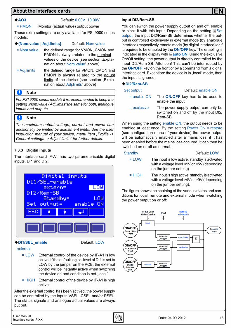
43User ManualInterface cards IF-XX
EN
Date: 04-09-2012
AO3 Default: 0.00V 10.00V = PMON Monitor (actual value) output powerThese extra settings are only available for PSI 9000 series models:Nom.value | Adj.limits Default: Nom.value = Nom.value the defined range for VMON, CMON and PMON is always related to the nominal values of the device (see section „Expla- nation about Nom.value“ above) = Adj.limits the defined range for VMON, CMON and PMON is always related to the adjust limits of the device (see section „Expla- nation about Adj.limits“ above)
NoteFor PSI 9000 series models it is recommended to keep the setting „Nom.value / Adj.limits“ the same for both, analogue inputs and outputs.
NoteThe maximum output voltage, current and power can additionally be limited by adjustment limits. See the user instruction manual of your device, menu item „Profile -> General settings -> Adjust limits“ for further details.
7.3.3 Digital inputsThe interface card IF-A1 has two parameterisable digital inputs, DI1 and DI2.
DI1/SEL_enable Default: LOW external = LOW External control of the device by IF-A1 is low
active. If the default logical level of DI1 is set to LOW by the jumper on the PCB, the external control will be instantly active when switching the device on and condition is not „local“.
= HIGH External control of the device by IF-A1 is highactive.
After the external control has been actived, the power supply can be controlled by the inputs VSEL, CSEL and/or PSEL. The status signale and analogue actual values are always put out.
About the interface cards
Input DI2/Rem-SBYou can switch the power supply output on and off, enable or block it with this input. Depending on the setting Set output, the input DI2/Rem-SB determines whether the out-put is controlled exclusively in external mode (by analogue interface) respectively remote mode (by digital interface) or if it requires to be enabled by the ON/OFF key. The enabling is indicated in the display with auto ON. Using the exclusive On/Off setting, the power output is directly controlled by the input DI2/Rem-SB. Attention! This can‘t be interrrupted by the ON/OFF key on the front or by a command from a digital interface card. Exception: the device is in „local“ mode, then the input is ignored.DI2/Rem-SB Set output Default: enable ON = enable ON The ON/OFF key has to be used to
enable the input = exclusive The power supply output can only be
switched on and off by the input DI2/Rem-SB
When using the setting enable ON, the output needs to be enabled at least once. By the setting Power ON = restore (see configuration menu of your device) the power output will be automatically enabled after a mains loss, if it has been enabled before the mains loss occured. It can then be switched on or off as normal. Standby Default: LOW = LOW The input is low active, standby is activated
with a voltage level <1V or <5V (depending on the jumper setting)
= HIGH The input is high active, standby is activated with a voltage level >4V or >9V (depending on the jumper setting).
The figure shows the chaining of the various states and con-ditions for local, remote and external mode when switching the power output on or off:
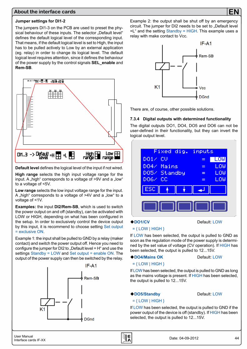
44User ManualInterface cards IF-XX
EN
Date: 04-09-2012
About the interface cards
Jumper settings for DI1-2The jumpers DI1-3 on the PCB are used to preset the phy-sical behaviour of these inputs. The selector „Default level“ defines the default logical level of the corresponding input. That means, if the default logical level is set to High, the input has to be pulled actively to Low by an external application (eg. relay) in order to change its logical level. The default logical level requires attention, since it defines the behaviour of the power supply by the control signals SEL_enable and Rem-SB.
Default level defines the logical level of the input if not wired.High range selects the high input voltage range for the input. A „high“ corresponds to a voltage of >9V and a „low“ to a voltage of <5V.Low range selects the low input voltage range for the input. A „high“ corresponds to a voltage of >4V and a „low“ to a voltage of <1V.Examples: the input DI2/Rem-SB, which is used to switch the power output on and off (standby), can be activated with LOW or HIGH, depending on what has been configured in the setup. In order to exclusively control the device output by this input, it is recommend to choose setting Set output = exclusive ON.Example 1: the input shall be pulled to GND by a relay (maker contact) and switch the power output off. Hence you need to configure the jumper for DI2 to „Default level = H“ and use the settings Standby = LOW and Set output = enable ON. The output of the power supply can then be switched by the relay.
Example 2: the output shall be shut off by an emergency circuit. The jumper for DI2 needs to be set to „Default level =L“ and the setting Standby = HIGH. This example uses a relay with make contact to Vcc.
There are, of course, other possible solutions.
7.3.4 Digital outputs with determined functionalityThe digital outputs DO1, DO4, DO5 and DO6 can not be user-defined in their functionality, but they can invert the logical output level.
DO1/CV Default: LOW = LOW | HIGH If LOW has been selected, the output is pulled to GND as soon as the regulation mode of the power supply is determi-ned by the set value of voltage (CV operation). If HIGH has been selected, the output is pulled to 12...15V.DO4/Mains OK Default: LOW = LOW | HIGH If LOW has been selected, the output is pulled to GND as long as the mains voltage is present. If HIGH has been selected, the output is pulled to 12...15V.
DO5/Standby Default: LOW = LOW | HIGH If LOW has been selected, the output is pulled to GND if the power output of the device is off (standby). If HIGH has been selected, the output is pulled to 12...15V.
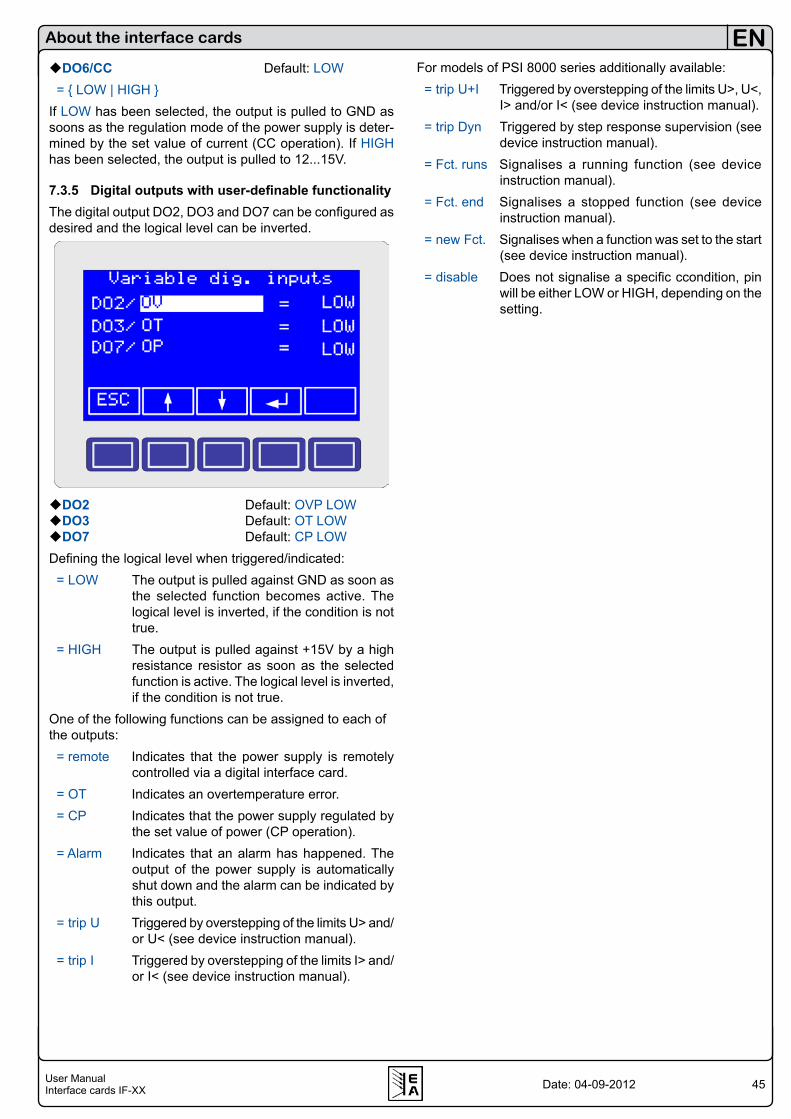
45User ManualInterface cards IF-XX
EN
Date: 04-09-2012
About the interface cards
DO6/CC Default: LOW = LOW | HIGH If LOW has been selected, the output is pulled to GND as soons as the regulation mode of the power supply is deter-mined by the set value of current (CC operation). If HIGH has been selected, the output is pulled to 12...15V.
7.3.5 Digital outputs with user-definable functionalityThe digital output DO2, DO3 and DO7 can be configured as desired and the logical level can be inverted.
DO2 Default: OVP LOWDO3 Default: OT LOWDO7 Default: CP LOWDefining the logical level when triggered/indicated: = LOW The output is pulled against GND as soon as
the selected function becomes active. The logical level is inverted, if the condition is not true.
= HIGH The output is pulled against +15V by a high resistance resistor as soon as the selected function is active. The logical level is inverted, if the condition is not true.
One of the following functions can be assigned to each of the outputs: = remote Indicates that the power supply is remotely
controlled via a digital interface card. = OT Indicates an overtemperature error. = CP Indicates that the power supply regulated by
the set value of power (CP operation). = Alarm Indicates that an alarm has happened. The
output of the power supply is automatically shut down and the alarm can be indicated by this output.
= trip U Triggered by overstepping of the limits U> and/or U< (see device instruction manual).
= trip I Triggered by overstepping of the limits I> and/or I< (see device instruction manual).
For models of PSI 8000 series additionally available: = trip U+I Triggered by overstepping of the limits U>, U<,
I> and/or I< (see device instruction manual). = trip Dyn Triggered by step response supervision (see
device instruction manual). = Fct. runs Signalises a running function (see device
instruction manual). = Fct. end Signalises a stopped function (see device
instruction manual). = new Fct. Signalises when a function was set to the start
(see device instruction manual). = disable Does not signalise a specific ccondition, pin
will be either LOW or HIGH, depending on the setting.

46User ManualInterface cards IF-XX
EN
Date: 04-09-2012
About the interface cards
8. GPIB card IF-G1The interface card IF-G1 offers a standardised, digital inter-face (GPIB) according to IEEE 488.1/2. The installation is described on the short install guide that is included in the package.
NoteIn case a second card is used inside a device of the se-ries PSI 9000, the IF-G1 can only be combined with the analogue card IF-A1 or the digital cards IF-R1 or IF-U1. It must not be plugged together with the CAN interface card IF-C1 or with the Ethernet card IF-E1B! See section 3.3.
8.1 Controlling a device via GPIBThe principle to access and control our devices is the same as with the other digital cards. Once the GPIB card is con-nected to a PC and has been configured, you can easily query status and actual values from the device. Controlling the device, like setting the input/output on or off or sending set values, requires to activate the remote control mode. This doesn‘t happen automatically. The corresponding commands are described in seperate documents.
NoteWith GPIB you can link only up to 15 client units on one bus!
8.2 Terms explainedGPIB General Purpose Interface BusIEEE60488.1 standardises GPIB interface to a host
computer (older synonyms: IEC bus, IEC 625 bus , ANSI standard MC1.1)
SCPI Standard Commands for Programmable Instruments => a standardised command language for communication with instru-mentes, measuring equipment etc.
8.3 Firmware updatesThe package includes a flat ribbon cable that is used for firmware updates of the microcontroller. In order to update, plug the cable to X5 on the PCB, insert the card carefully into the device again and connect the Sub-D plug to a PC via a 9pole Sub-D cable of „null modem“ type (not included). A seperately obtainable update tool can either be downloaded from your supplier‘s website or is obtainable upon request.
8.4 Transmission and execution timesThe SCPI protocol needs to be translated into the internal one and thus consumes some time.The protocol translation time and the execution time of the device‘s internal microcontroller are dependent on the command and have to be added to the transmission time. Typical values are:Time of protocol translation TP: 2msTransmission time to the internal microcontroller TT,MC: 0.5msExecution time of the internal microcontroller TE,MC: 2ms
In case the host PC is expecting a response, a total time of
, , ,
, ,0,2Request T GPIB P T MC E MC
Response T MC P T GPIB
T T T T TT T T T
= + + +
= + + • +
can result, depending on the
command sent.The transmission time TT,GPIB of the GPIB bus is very short and lies with typical 200μs. The recommended command interval time is >30ms. Smaller times can lead to execution errors.
8.5 Configuring the IF-G1The card is configured in the setup menu.Note: it is definitely necessary to choose a unique „device node“ (=address) for every unit that is connected to the same PC. Only then the device can be identified and addressed correctly. Accessing the setup menu:
M + Communication + and
Slot: IF-G1 +
Here you can set the device node, which equals to the GPIB address.
NoteIn case the settings are changed without restarting the device, you are required to send the *RST command in order to submit the new settings.
Attention!With power supply series PSI 9000 up to firmware ver-sion 3.04 resp. with electronic load series EL3000/9000 up to firmware version 2.11, the interface card is not recognized correctly. Contact your dealer for details.
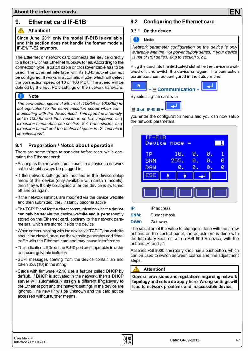
47User ManualInterface cards IF-XX
EN
Date: 04-09-2012
About the interface cards
9. Ethernet card IF-E1BAttention!
Since June, 2011 only the model IF-E1B is available and this section does not handle the former models IF-E1/IF-E2 anymore.
The Ethernet or network card connects the device directly to a host PC or via Ethernet hubs/switches. According to the connection type, a patch cable or crossover cable has to be used. The Ethernet interface with its RJ45 socket can not be configured. It works in automatic mode, which will detect the connection speed of 10 or 100 MBit. The speed will be defined by the host PC‘s settings or the network hardware.
NoteThe connection speed of Ethernet (10Mbit or 100MBit) is not equivalent to the communication speed when com-municating with the device itself. This speed is internally set to 100kBit and thus results in certain response and execution times. Also see section „8.4 Transmission and execution times“ and the technical specs in „2. Technical specifications“.
9.1 Preparation / Notes about operationThere are some things to consider before resp. while ope-rating the Ethernet card:• As long as the network card is used in a device, a network
cable should always be plugged in• If the network settings are modified in the device setup
menu of the device (only available with certain models), then they will only be applied after the device is switched off and on again.
• If the network settings are modified via the device website and then submitted, they instantly become active
• The TCP/IP port for the direct communication with the device can only be set via the device website and is permanently stored on the Ethernet card, contrary to the network para-meters, which are stored inside the device
• When communicating with the device via TCP/IP, the website should be closed, because the website generates additional traffic with the Ethernet card and may cause interference
• The indication LEDs on the RJ45 port are inoperable in order to ensure galvanic isolation
• SCPI messages coming from the device contain an end token 0xA (10) in the string
• Cards with firmware <2.10 use a feature called DHCP by default. If DHCP is activated in the network, then a DHCP server will automatically assign a different IP/gateway to the Ethernet port and the network settings in the device are ignored. The new IP will be unknown and the card not be accessed without further means.
9.2 Configuring the Ethernet card
9.2.1 On the device
NoteNetwork parameter configuration on the device is only available with the PSI power supply series. If your device is not of PSI series, skip to section 9.2.2.
Plug the card into the dedicated slot while the device is swit-ched off, and switch the device on again. The connection parameters can be configured in the setup menu:
M +Communication +
By selecting the card with
Slot: IF-E1B + you enter the configuration menu and you can now setup the network parameters:
IP: IP addressSNM: Subnet maskDGW: GatewayThe selection of the value to change is done with the arrow buttons on the control panel, the adjustment is done with the left rotary knob or, with a PSI 800 R device, with the buttons „+“ and „-“.At series PSI 8000, the rotary knob has a pushbutton, which can be used to switch between coarse and fine adjustment steps.
Attention!General provisions and regulations regarding network topology and setup do apply here. Wrong settings will lead to network problems and inaccessible device.
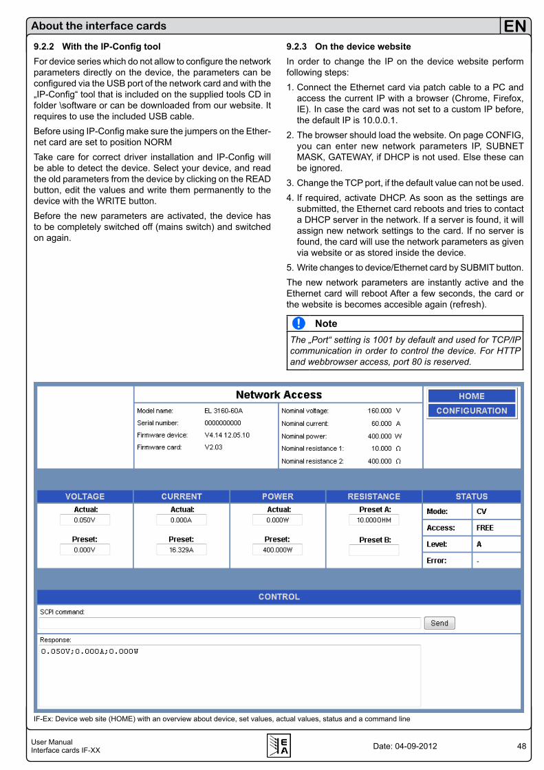
48User ManualInterface cards IF-XX
EN
Date: 04-09-2012
About the interface cards
9.2.2 With the IP-Config toolFor device series which do not allow to configure the network parameters directly on the device, the parameters can be configured via the USB port of the network card and with the „IP-Config“ tool that is included on the supplied tools CD in folder \software or can be downloaded from our website. It requires to use the included USB cable.Before using IP-Config make sure the jumpers on the Ether-net card are set to position NORMTake care for correct driver installation and IP-Config will be able to detect the device. Select your device, and read the old parameters from the device by clicking on the READ button, edit the values and write them permanently to the device with the WRITE button.Before the new parameters are activated, the device has to be completely switched off (mains switch) and switched on again.
9.2.3 On the device websiteIn order to change the IP on the device website perform following steps:1. Connect the Ethernet card via patch cable to a PC and
access the current IP with a browser (Chrome, Firefox, IE). In case the card was not set to a custom IP before, the default IP is 10.0.0.1.
2. The browser should load the website. On page CONFIG, you can enter new network parameters IP, SUBNET MASK, GATEWAY, if DHCP is not used. Else these can be ignored.
3. Change the TCP port, if the default value can not be used. 4. If required, activate DHCP. As soon as the settings are
submitted, the Ethernet card reboots and tries to contact a DHCP server in the network. If a server is found, it will assign new network settings to the card. If no server is found, the card will use the network parameters as given via website or as stored inside the device.
5. Write changes to device/Ethernet card by SUBMIT button.The new network parameters are instantly active and the Ethernet card will reboot After a few seconds, the card or the website is becomes accesible again (refresh).
NoteThe „Port“ setting is 1001 by default and used for TCP/IP communication in order to control the device. For HTTP and webbrowser access, port 80 is reserved.
IF-Ex: Device web site (HOME) with an overview about device, set values, actual values, status and a command line

49User ManualInterface cards IF-XX
EN
Date: 04-09-2012
About the interface cards
9.3 Communicating with the deviceGeneral informationThe communication with the device is done with the TCP/IP protocol via a user-selectable port. The default port is 1001. The port can only be changed on the device website, see section 9.2.3 for more information. Following ports are available:Port 80: HTTPPorts 0-65535, except 80: TCP/IP
9.3.1 Communication via HTTPThe network cards features a HTTP server. When accessing the IP of the device by a web browser, a graphical user in-terface appears which displays information about the device such as device type, nominal values, actual values and set values. This web site can also be used to remotely control the device and configure the network settings.Remote control is done with SCPI commands. The command set is described in external user guides. Refer to section „13. Programming“ for an overview. The commands are input as plain ASCII strings into the command line and sent by hitting the Return key or by clicking the SEND button. The error and response box below the command line will report errors and display queried values.Notes & requirements:• Requires Javascript enabled for refresh and content• Refresh interval (values, status): 200ms• SCPI commands can also be entered in lowercase• The web site allows port selection for TCP/IP communi-
cation
9.3.2 Communication in LabViewLabView has implemented VIs for interface communication via TCP/IP (VISA) by default. These can be used according to their given handling instruction. Further information can also be found on the internet. There is also a set of VIs included on the tools CD, which will simplify the remote control of your device via Ethernet.
9.3.3 Communication in other programming languagesThe user has to establish the appropriate communication with TCP/IP protocol in order to transport SCPI commands as correct ASCII strings to the device. Based upon the manifold of operating systems and programming languages, there are no libraries (DLL) or code examples available.For a socket connection, only IP and port of the target device are required. The port can only be changed via the device website and is stored on the interface card.It is allowed to keep the socket connection open as long as communication with the device is continued. Permanent closing and opening of the socket is also possible, but con-sumes more time.
9.3.4 Communication via the USB portThe Ethernet card features an additional interface, a USB port of type A. This interface works identically to the IF-U1 USB card,. Also see section 5.When using USB, following applies:• No SCPI commands, no TCP/IP, no HTTP, no website• Transmission speed is fixed to 57600 baud• USB driver required• Communication via LabView and other languages only with
the object orientated communication protocol (see section 7.) resp. the corresponding LabView VIs.
IF-Ex: Javascript error
50User ManualInterface cards IF-XX
EN
Date: 04-09-2012
About the interface cards
9.4 Firmware updatesThe additional USB port is also used to update the firmware of the device or the Ethernet card itself.Firmware updates are done with a special update tool and a new firmware version, which are obtainable from the ma-nufacturer of the device.
9.5 Trouble-shootingProblem: Device is not respondingIn case the connection to a device somehow hangs or drops completely and attempts to re-establish the connection fail, the interface card can be reseted with the small reset button on the card.The card will reboot after the manual reset and initialise the network connection again so that the device becomes accessible again.
Problem: IP of a device is unkown or forgottenDevices with a graphical display can show the network pa-rameters in the setup menu.Other models, like for example a PS 8000 T, can not show the IP. Here it is required to use the little tool „IP-Config“, which supplied on the included CD. Via the USB port connection and with the jumpers on the interface card set to position NORM, the tool can read and write the network configuration.
Problem: The device can not be accessed via its IPThis can have several reasons:1. The Ethernet card could not be detected by the deviceIf a device can not detect and thus initialise the Ethernet card, the Ethernet will reboot every few seconds and the network connection will constantly open and close. Check your device...• electronic load EL 3000 / EL 9000 for showing „Card found:
IF-E1 (Ethernet“ in the display (switch „Level Control“ in position „Setup“
• power supply of series PSI 8000 or PSI 800 R for showing „Slot: IF-E1“ in menu „Communication“
• power supply of series PS 8000 for showing „Device node“ in the setup mode
If this is not display, the card slot may be defective, the card itself may be defective or the card is not installed correctly.2. The IP is a different network segmentA subnet mask defines what local IPs are accessible in the network. The subnet mask, as set for the IF-E1B Ethernet, has to match the subnet mask of the network. You can eit-her change the subnet mask or the IP to access the device again via its IP.3. The TCP port has closedThe keep-alive timeout of the Ethernet card IF-E1B is 10min. If there is data communication during this period, the TCP port will be closed on the device side.
4. The device has a different IP than expectedIf DHCP has been activated and there is a DHCP server running on the network, the network settings, as given by you via website, IP-Config tool or directly in the setup menu, will be overriden and automatically assigned new values. The new IP is unknown at first. In order to switch DHCP off for the Ethernet card, you need to detect the IP first. This can be done using a network scanner tool, which also lists the MAC address of detected network devices. The MAC address (see sticker on the IF-E1B) can be used to identify the Ethernet card and to find the assigned IP. Open the IP in a browser and switch DHCP off, if required.
Problem: The LEDs on the network port do not workThis is no error, this is intended in orde to ensure the full galvanic isolation of up to 1500V against the device.
Problem: When connecting more than IF-E1B to the network, one or all devices with IF-E1B can not be connectedThis can happen with older firmware versions. Up to version 2.08, the IF-E1B might not use the correct MAC address in some situations. It then uses a generic MAC adress which unfortunately is the same on all cards concerned by this problem. It can only be solved by performing a firmware update on the Ethernet card(s).From firmware 2.09, if the Ethernet card can not use the implemented MAC address by any reason, it will use a MAC address where the first three bytes are always the same and the rest is generated from the serial number of the card, so the new MAC address becomes unique.
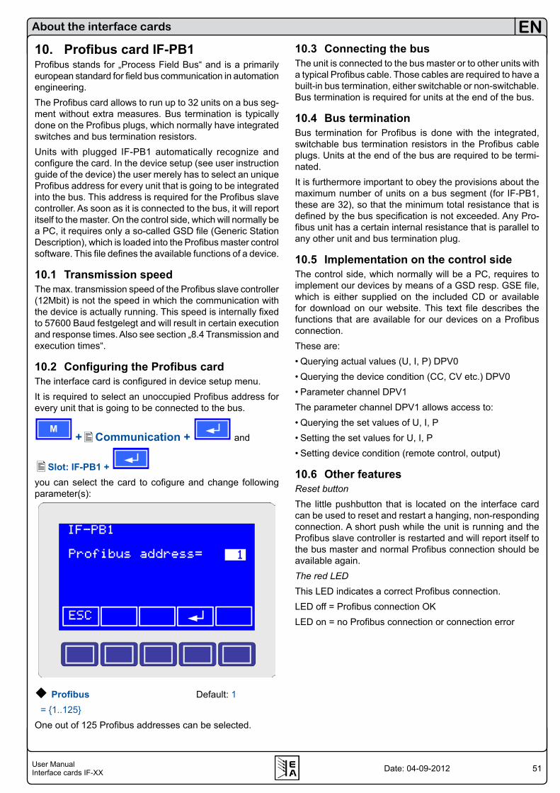
51User ManualInterface cards IF-XX
EN
Date: 04-09-2012
About the interface cards
10. Profibus card IF-PB1Profibus stands for „Process Field Bus“ and is a primarily european standard for field bus communication in automation engineering.The Profibus card allows to run up to 32 units on a bus seg-ment without extra measures. Bus termination is typically done on the Profibus plugs, which normally have integrated switches and bus termination resistors.Units with plugged IF-PB1 automatically recognize and configure the card. In the device setup (see user instruction guide of the device) the user merely has to select an unique Profibus address for every unit that is going to be integrated into the bus. This address is required for the Profibus slave controller. As soon as it is connected to the bus, it will report itself to the master. On the control side, which will normally be a PC, it requires only a so-called GSD file (Generic Station Description), which is loaded into the Profibus master control software. This file defines the available functions of a device.
10.1 Transmission speedThe max. transmission speed of the Profibus slave controller (12Mbit) is not the speed in which the communication with the device is actually running. This speed is internally fixed to 57600 Baud festgelegt and will result in certain execution and response times. Also see section „8.4 Transmission and execution times“.
10.2 Configuring the Profibus cardThe interface card is configured in device setup menu.It is required to select an unoccupied Profibus address for every unit that is going to be connected to the bus.
M +Communication + and
Slot: IF-PB1 + you can select the card to cofigure and change following parameter(s):
Profibus Default: 1 = 1..125 One out of 125 Profibus addresses can be selected.
10.3 Connecting the busThe unit is connected to the bus master or to other units with a typical Profibus cable. Those cables are required to have a built-in bus termination, either switchable or non-switchable.Bus termination is required for units at the end of the bus.
10.4 Bus terminationBus termination for Profibus is done with the integrated, switchable bus termination resistors in the Profibus cable plugs. Units at the end of the bus are required to be termi-nated.It is furthermore important to obey the provisions about the maximum number of units on a bus segment (for IF-PB1, these are 32), so that the minimum total resistance that is defined by the bus specification is not exceeded. Any Pro-fibus unit has a certain internal resistance that is parallel to any other unit and bus termination plug.
10.5 Implementation on the control sideThe control side, which normally will be a PC, requires to implement our devices by means of a GSD resp. GSE file, which is either supplied on the included CD or available for download on our website. This text file describes the functions that are available for our devices on a Profibus connection.These are:• Querying actual values (U, I, P) DPV0 • Querying the device condition (CC, CV etc.) DPV0• Parameter channel DPV1The parameter channel DPV1 allows access to:• Querying the set values of U, I, P• Setting the set values for U, I, P• Setting device condition (remote control, output)
10.6 Other featuresReset buttonThe little pushbutton that is located on the interface card can be used to reset and restart a hanging, non-responding connection. A short push while the unit is running and the Profibus slave controller is restarted and will report itself to the bus master and normal Profibus connection should be available again.The red LEDThis LED indicates a correct Profibus connection.LED off = Profibus connection OKLED on = no Profibus connection or connection error
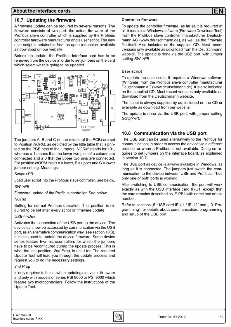
52User ManualInterface cards IF-XX
EN
Date: 04-09-2012
10.7 Updating the firmwareA firmware update can be required by several reasons. The firmware consists of two part: the actual firmware of the Profibus slave controller which is supplied by the Profibus controller hardware manufacturer and a user script. The new user script is obtainable from us upon request or available as download on our website. Before the update, the Profibus interface card has to be removed from the device in order to set jumpers on the card which select what is going to be updated.
Blatt 1 / 2
The jumpers A, B and C (in the middle of the PCB) are set to Position NORM, as depicted by the little table that is prin-ted on the PCB next to the jumpers. NORM stands for 101, whereas a 1 means that the lower two pins of a column are connected and a 0 that the upper two pins are connected. For position NORM this is A = lower, B = upper and C = lower jumper setting. Meanings:Script->PBLoad user script into the Profibus slave controller. See below.SW->PBFirmware update of the Profibus controller. See below.NORMSetting for normal Profibus operation. This position is re-quired to be set after every script or firmware update.USB<->Dev.Activates the connection of the USB port to the device. The device can now be accessed by communcation via the USB port, as an alternative communication way (see section 10.8). It is also used to update the device firmware. Some device series feature two microcontrollers for which the jumpers have to be reconfigured during the update process. This is what the last position, 2nd Prog, is used for. The required Update Tool will lead you through the update process and request you to do the necessary settings.2nd ProgIs only required to be set when updating a device‘s firmware and only with models of series PSI 8000 or PSI 9000 which feature two microcontrollers. Follow the instructions of the Update Tool.
Controller firmwareTo update the controller firmware, as far as it is required at all, it requires a Windows software (Firmware Download Tool) from the Profibus slave controller manufacturer Deutsch-mann AG (www.deutschmann.de), as well as the firmware file itself. Also included on the supplied CD. Most recent versions only available as download from the Deutschmann website. The update is done via the USB port, with jumper setting SW->PB.
User scriptTo update the user script, it requires a Windows software (WinGate) from the Profibus slave controller manufacturer Deutschmann AG (www.deutschmann.de). It is also included on the supplied CD. Most recent versions only available as download from the Deutschmann website. The script is always supplied by us, included on the CD or available as download from our websiteThe update is done via the USB port, with jumper setting Script->PB.
10.8 Communication via the USB portThe USB port can be used alternatively to the Profibus for communication, in order to access the device via a different protocol or when a Profibus is not available. Doing so re-quires to set jumpers on the interface board, as explained in section 10.7.The USB port as device is always available in Windows, as long as it is connected. The jumpers just switch the com-munication to the device between USB and Profibus. Thus only one of both ports is working.After switching to USB communication, the port will work exactly as with the USB interface card IF-U1, except that the card remains described as IF-PB1 with name and article number.Refer to sections „5. USB card IF-U1 / IF-U2“ and „13. Pro-gramming“ for details about communication, programming and setup of the USB port.
About the interface cards

53User ManualInterface cards IF-XX
EN
Date: 04-09-2012
About the interface cards
11. Notes about particular device series11.1 Series EL 3000 / EL 9000The electronic loads of the series EL3000 and EL9000 sup-port the following interface cards (date 08 /2012):IF-U1, IF-R1, IF-C1, IF-G1* and IF-E1**Note about the GPIB card IF-G1: at devices with firmware version 2.10 or older the card is detected as IF-C1 (CAN card) and must be configured to following settings:- CAN Baudrate: 100kBd- Bus termination: no- Relocatable ID: 0Also, in devices with firmware older than 3.01, the card is detected but not correctly supported. We recommend an update. Please contact your dealer.From firmware version 3.01 there are no limitations.You can configure the interface cards in the setup menu of the devices. This is activated by turning the switch Level Control to position Setup. Depending on which card is equipped, a different selection of parameters is available. The parameters and their values are identical to the ones explained in section 4 to 8, with the exception that no Sample point can be set at CAN.There are also no settable parameters for the USB and IEEE card.*) since firmware 2.11
**) since firmware 4.07
11.2 Series PS 8000 T/ DT / 2U / 3UAccess to the device setup via pushbutton Fine (press >2s while output is „off“), for details of settings see user manual of the device. The GPIB, USB and Ethernet don‘t require configuration resp. can not be configured in the setup.
11.3 Series PSI 800 R and BCI 800 RThe shortened type 2 cards are used here. Setup and con-figuration are explained in the user guide of the device and also in section 4. to 9. Menu structure and handling of PSI 800 R series is similiar to PSI 8000 series.
EL 3000/9000 Menu example of the CAN card:
EL 3000/9000 Menu example RS232 card:
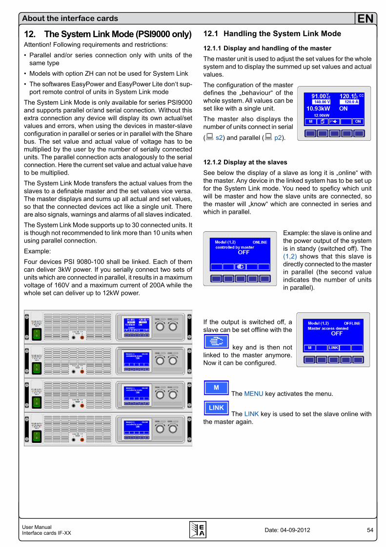
54User ManualInterface cards IF-XX
EN
Date: 04-09-2012
About the interface cards
12. The System Link Mode (PSI9000 only)Attention! Following requirements and restrictions:• Parallel and/or series connection only with units of the
same type• Models with option ZH can not be used for System Link• The softwares EasyPower and EasyPower Lite don‘t sup-
port remote control of units in System Link modeThe System Link Mode is only available for series PSI9000 and supports parallel or/and serial connection. Without this extra connection any device will display its own actual/set values and errors, when using the devices in master-slave configuration in parallel or series or in parallel with the Share bus. The set value and actual value of voltage has to be multiplied by the user by the number of serially connected units. The parallel connection acts analogously to the serial connection. Here the current set value and actual value have to be multiplied. The System Link Mode transfers the actual values from the slaves to a definable master and the set values vice versa. The master displays and sums up all actual and set values, so that the connected devices act like a single unit. There are also signals, warnings and alarms of all slaves indicated.The System Link Mode supports up to 30 connected units. It is though not recommended to link more than 10 units when using parallel connection.Example:Four devices PSI 9080-100 shall be linked. Each of them can deliver 3kW power. If you serially connect two sets of units which are connected in parallel, it results in a maximum voltage of 160V and a maximum current of 200A while the whole set can deliver up to 12kW power.
12.1 Handling the System Link Mode
12.1.1 Display and handling of the masterThe master unit is used to adjust the set values for the whole system and to display the summed up set values and actual values. The configuration of the master defines the „behaviour“ of the whole system. All values can be set like with a single unit.The master also displays the number of units connect in serial
( s2) and parallel ( p2).
12.1.2 Display at the slavesSee below the display of a slave as long it is „online“ with the master. Any device in the linked system has to be set up for the System Link mode. You need to speficy which unit will be master and how the slave units are connected, so the master will „know“ which are connected in series and which in parallel.
Example: the slave is online and the power output of the system is in standy (switched off). The (1,2) shows that this slave is directly connected to the master in parallel (the second value indicates the number of units in parallel).
If the output is switched off, a slave can be set offline with the
key and is then not linked to the master anymore. Now it can be configured.
M The MENU key activates the menu.
LINK The LINK key is used to set the slave online with
the master again.
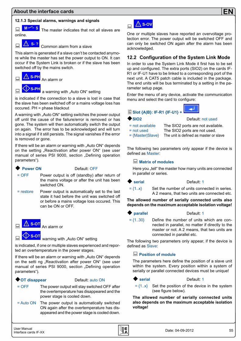
55User ManualInterface cards IF-XX
EN
Date: 04-09-2012
About the interface cards
12.1.3 Special alarms, warnings and signals
M S The master indicates that not all slaves are online.
S- ? Common alarm from a slaveThis alarm is generated if a slave can’t be contacted anymo-re while the master has set the power output to ON. It can occur if the System Link is broken or if the slave has been switched off by the mains switch.
S-PH An alarm or
S-PH a warning with „Auto ON“ setting
is indicated if the connection to a slave is lost in case that the slave has been switched off or a mains voltage loss has occured. PH = phase blackoutA warning with „Auto ON“ setting switches the power output off until the cause of the failure/error is removed or has gone. The system will then automatically switch the output on again. The error has to be acknowledged and will turn into a signal if it still persists. The signal vanishes if the error is removed or gone.If there will be an alarm or warning with „Auto ON“ depends on the setting „Reactivation after power ON“ (see user manual of series PSI 9000, section „Defining operation parameters“).
Power ON Default: OFF = OFF Power output is off (standby) after return of
the mains voltage or after the unit has been switched ON.
= restore Power output is automatically set to the last state it had before the unit was switched off or before a mains voltage loss occured. This can be ON or OFF.
S-OT An alarm or
S-OT warning with „Auto ON“ setting
is indicated, if one or multiple slaves experienced and repor-ted an overtemperature in the power stages.If there will be an alarm or warning with „Auto ON“ depends on the setti ng „Reactivation after power ON“ (see user manual of series PSI 9000, section „Defining operation parameters“).
OT disappear Default: auto ON = OFF The power output will stay switched OFF after
the overtemperature has disappeared and the power stage is cooled down.
= Auto ON The power output is automatically switched ON again after the overtemperature has dis-appeared and the power stage is cooled down.
S-OV
One or multiple slaves have reported an overvoltage pro-tection error. The power output will be switched OFF and can only be switched ON again after the alarm has been acknowledged.
12.2 Configuration of the System Link ModeIn order to use the System Link Mode it first has to be set up and configured. The extra ports (SIO2) on the cards IF-R1 or IF-U1 have to be linked to a corresponding port of the next unit. A CAT5 patch cable is included in the package. The end units will be bus terminated by a setting in the pa-rameter setup page.Enter the menu of any device, activate the communication menu and select the card to configure:
Slot A|B: IF-R1 IF-U1 + SIO2 Default: not used = not available The SIO2 ports are not available. = not used The SIO2 ports are not used. = Master|Slave The unit is defined as master or slave
The following two parameters only appear if the device is defined as Master:
Matrix of modules Here you „tell“ the master how many units are connected in parallel or series.
serial Default: 1 = 1..x Set the number of units connected in series.
A 2 means, that two units are connected etc.The allowed number of serially connected units also depends on the maximum acceptable isolation voltage!
parallel Default: 1 = 1..30 Define the number of units which are con-
nected in parallel, no matter if directly to the master or not. A 2 means, that two units are connected in parallel etc.
The following two parameters only appear, if the device is defined as Slave:
Position of moduleThe parameters here define the position of a slave unit within the system. Every position within a system of serially or parallel connected devices must be unique!
serial Default: 1 = 1..x Set the position of the device in the system
(see figure below).The allowed number of serially connected units also depends on the maximum acceptable isolation voltage!
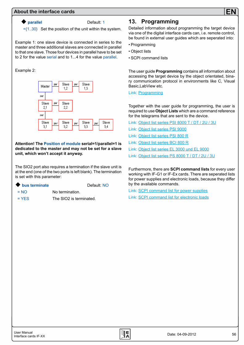
56User ManualInterface cards IF-XX
EN
Date: 04-09-2012
About the interface cards
parallel Default: 1 =1..30 Set the position of the unit within the system.
Example 1: one slave device is connected in series to the master and three additional slaves are connected in parallel to that one slave. Those four devices in parallel have to be set to 2 for the value serial and to 1...4 for the value parallel.
Example 2:
Attention! The Position of module serial=1/parallel=1 is dedicated to the master and may not be set for a slave unit, which won’t accept it anyway.
The SIO2 port also requires a termination if the slave unit is at the end (one of the two ports is left blank). The termination is set with this parameter:
bus terminate Default: NO = NO No termination. = YES The SIO2 is terminated.
13. ProgrammingDetailed information about programming the target device via one of the digital interface cards can, i.e. remote control, be found in external user guides which are seperated into:• Programming• Object lists• SCPI command lists
The user guide Programming contains all information about accessing the target device by the object orientated, bina-ry communication protocol in environments like C, Visual Basic,LabView etc.Link: Programming
Together with the user guide for programming, the user is required to use Object Lists which are a command reference for the telegrams that are sent to the device.Link: Object list series PSI 8000 T / DT / 2U / 3ULink: Object list series PSI 9000Link: Object list series PSI 800 RLink: Object list series BCI 800 RLink: Object list series EL 3000 und EL 9000Link: Object list series PS 8000 T / DT / 2U / 3U
Furthermore, there are SCPI command lists for every user working with IF-G1 or IF-Ex cards. There are seperated lists for power supplies and electronic loads, because they differ by the available commands.Link: SCPI command list for power suppliesLink: SCPI command list for electronic loads
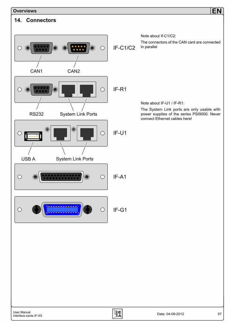
57User ManualInterface cards IF-XX
EN
Date: 04-09-2012
14. Connectors
Overviews
Note about If-C1/C2:The connectors of the CAN card are connected in parallel
Note about IF-U1 / IF-R1:The System Link ports are only usable with power supplies of the series PSI9000. Never connect Ethernet cables here!
CAN1 CAN2
RS232 System Link Ports
System Link PortsUSB A
IF-C1/C2
IF-R1
IF-A1
IF-G1
IF-U1
1
112
1324

58User ManualInterface cards IF-XX
EN
Date: 04-09-2012
LAN USB AReset
USB A
USB A ProfibusStatus
IF-E1BIF-E2
IF-R2
IF-U2
IF-PB1
Overviews

EA-Elektro-Automatik GmbH & Co. KGEntwicklung - Produktion - VertriebDevelopment - Production - Sales
Helmholtzstraße 31-3341747 Viersen
Germany
Telefon: +49 (0) 2162 / 37 85-0Telefax: +49 (0) 2162 / 16 [email protected]
www.elektroautomatik.de