Numerical Investigation of Droplet-Droplet Coalescence and Droplet-Interface Coalescence

International Journal of Solids and Structures 48 (2011) 1696–1710
Contents lists available at ScienceDirect
International Journal of Solids and Structures
journal homepage: www.elsevier .com/locate / i jsolst r
Void growth and coalescence in anisotropic plastic solids
S.M. Keralavarma ⇑, S. Hoelscher, A.A. BenzergaDepartment of Aerospace Engineering, Texas A&M University, College Station, TX 77843-3141, USA
a r t i c l e i n f o
Article history:Received 16 May 2010Received in revised form 16 February 2011Available online 26 February 2011
Keywords:A. Ductile fractureA. Voids and inclusionsB. Finite element analysisB. Porous metal plasticityC. AnisotropyC. Constitutive behavior
0020-7683/$ - see front matter � 2011 Elsevier Ltd. Adoi:10.1016/j.ijsolstr.2011.02.020
⇑ Corresponding author.E-mail address: [email protected] (S.M. Ker
a b s t r a c t
Large strain finite element calculations of unit cells subjected to triaxial axisymmetric loadings are pre-sented for plastically orthotropic materials containing a periodic distribution of aligned spheroidal voids.The spatial distribution of voids and the plastic flow properties of the matrix are assumed to respecttransverse isotropy about the axis of symmetry of the imposed loading so that a two-dimensional axi-symmetric analysis is adequate. The parameters varied pertain to load triaxiality, matrix anisotropy, ini-tial porosity and initial void shape so as to include the limiting case of penny-shaped cracks. Attention isfocussed on comparing the individual and coupled effects of void shape and material anisotropy on theeffective stress–strain response and on the evolution of microstructural variables. In addition, the effectof matrix anisotropy on the mode of plastic flow localization is discussed. From the results, two distinctregimes of behavior are identified: (i) at high triaxialities, the effect of material anisotropy is found to bepersistent, unlike that of initial void shape and (ii) at moderate triaxialities the influence of void shape isfound to depend strongly on matrix anisotropy. The findings are interpreted in light of recent, microscop-ically informed models of porous metal plasticity. Conversely, observations are made in relation to therelevance of these results in the development and calibration of a broader set of continuum damagemechanics models.
� 2011 Elsevier Ltd. All rights reserved.
1. Introduction
Ductile fracture in structural materials results from the nucle-ation, growth and coalescence of micro-voids that initiate from sec-ond phase particles and inclusions. Accurate modeling of voidgrowth and coalescence under arbitrary imposed loading condi-tions is critical to the predictive modeling of ductile fracture.Gurson (1977) derived an analytical model of void growth in an iso-tropic medium based on analysis of a spherical representative vol-ume element (RVE) made of an ideal plastic von Mises materialand containing a concentric spherical void. The somewhat idealizedchoice of the RVE geometry was dictated by the complexity of theanalytical approach. Alternatively, finite element (FE) calculationsof appropriately chosen unit cells subjected to a remote triaxialloading have been used to simulate periodic arrays of voids.Needleman (1972) performed a two-dimensional plane-strain anal-ysis of a periodic array of cylindrical voids in an isotropic matrix,while a transverse isotropic distribution of spherical voids in an iso-tropic matrix was analyzed by Tvergaard (1982) and later by Koplikand Needleman (1988). The finite element results were used asbenchmarks to calibrate the Gurson model and heuristic correc-tions were suggested to enhance the quantitative agreement be-tween the model and the cell calculations (Tvergaard, 1982;
ll rights reserved.
alavarma).
Tvergaard and Needleman, 1984). Subsequently, three-dimensionalinvestigations of cubic patterns of spherical voids (Hom andMcMeeking, 1989; Worswick and Pick, 1990) under triaxial load-ings have evidenced good agreement with the axisymmetric calcu-lations. In particular, these unit cell computations identified theporosity and the loading triaxiality (the ratio of the mean to thevon Mises effective stress) as key parameters affecting void growthand coalescence. More recent unit cell analyses of initially sphericalvoids have also shown some influence of the third invariant of thestress tensor, through the Lode parameter, on void growth and coa-lescence (Benzerga and Besson, 2001; Zhang et al., 2001; Kim et al.,2004; Gao and Kim, 2006; Barsoum and Faleskog, 2007). FE Cellmodel studies have de facto become a major tool in understandingmaterial behavior at intermediate scales and were recently re-viewed by Benzerga and Leblond (2010), including aspects pertain-ing to the void nucleation stage.
In recent years, various extensions of the Gurson model havebeen proposed which account for initial or deformation-inducedanisotropies (Gologanu et al., 1993, 1997; Benzerga and Besson,2001; Monchiet et al., 2008; Keralavarma and Benzerga, 2008,2010). The commonality among these models is that they arebased on micromechanical treatments, with homogenization andlimit analysis being the theoretical foundation (Benzerga andLeblond, 2010). The performance of the model of Gologanu et al.(1997) in predicting void shape effects has been assessed bySovik and Thaulow (1997), and more thoroughly by Pardoen and

S.M. Keralavarma et al. / International Journal of Solids and Structures 48 (2011) 1696–1710 1697
Hutchinson (2000), who used the unit cell model considering ini-tially spheroidal voids in an isotropic matrix. Similarly, Benzergaand Besson (2001) carried out a series of unit cell calculations forinitially spherical voids embedded in a transversely isotropic ma-trix. They have shown that their extension of the Gurson modelto orthotropic matrices provided a good quantitative predictionof the voided cell results for sufficiently high stress triaxialities.
However, the more general models that combine effects of voidshape and plastic anisotropy have not yet been assessed againstthe voided cell model. Keralavarma and Benzerga (2010) presentedsome preliminary results to motivate their development of a newporous metal plasticity model. Also, their set of calculations fo-cussed on pre-localization void growth. The objective of this paperis to report on a large set of such calculations, probing the param-eter space much beyond the report of Keralavarma and Benzerga(2010). While we offer new findings by means of the voided cellmodel, the present results can also serve as reference to calibrateadvanced models of ductile fracture. General conditions of trans-verse isotropy are discussed and used, thus enabling a two-dimen-sional axisymmetric analysis. Emphasis is laid on the combinedeffects of void shape and matrix anisotropy on void growth and
Fig. 1. Idealized representation of the microstructure in the voided cell model: (a) hexagoused in the axisymmetric calculations: (c) front view and (d) top view.
micro-scale flow localization, the latter setting the stage for voidcoalescence.
2. Problem formulation
The void distribution in the plane of transverse isotropy of thematrix is an approximation of a hexagonal arrangement. Such amicrostructure may be constructed from an infinite repetition ofthe unit cell sketched in Fig. 1a. The hatched bands in the figureschematically represent the texture of the matrix. Fig. 1b showsa planar cross section of the unit cell in Fig. 1a. A cylindrical unitcell is taken to approximate this hexagonal arrangement and issketched in Fig. 1c (front view) and Fig. 1d (top view). The bound-aries of the unit cell are constrained to remain straight from con-siderations of periodicity, in the absence of shear loading, so thatthe RVE retains its cylindrical shape during deformation. Exploitingthe symmetry of the problem, one only needs to mesh the shadedregion in Fig. 1b. Let (eL,eT,eS) denote the triad associated with theorthotropy of the matrix (Fig. 1c). We also define a Cartesian coor-dinate system (e1,e2,e3) as shown in Fig. 1d where e3 is aligned
nal periodic unit and (b) cross-section in the plane of the paper. Cylindrical unit cell

1698 S.M. Keralavarma et al. / International Journal of Solids and Structures 48 (2011) 1696–1710
with the common axis of the voids. The latter is itself identifiedwith the axis of transverse isotropy of the matrix, i.e. e3 � eS, sothat the effective behavior of the unit cell is transversely isotropic,and one may perform axisymmetric calculations.
Our finite element implementation of the voided cell model fol-lows that of Benzerga and Besson (2001) using the object orientedcode ZeBuLoN (Besson and Foerch, 1997). The weak form of themomentum balance for a body undergoing finite deformations inthe absence of body forces is generally written asZ
VS : dEdV ¼
ZS
T � dudS ð1Þ
with
S ¼ JF�1 � r � F�T; E ¼ 12ðFT � F� IÞ; ð2Þ
where S is the symmetric second Piola–Kirchoff stress tensor, E isthe Green–Lagrange strain, F is the deformation gradient, J = det(F), I is the second-order identity tensor, r is the Cauchy stress, Tis the surface traction in the reference configuration, u is thedisplacement vector and V and S are respectively the volume andsurface of the body in the reference configuration. An updatedLagrangian formulation is used (Ladeveze, 1980; Hughes andWinget, 1980) which employs objective space frames with the ref-erence configuration being chosen at the end of the increment sothat the stress measure S reduces to the Cauchy stress.
The material constitutive model is assumed to be that of a rate-independent elastically isotropic and plastically anisotropic solid.In the objective frame, the deformation rate tensor is written asthe sum of an elastic part, de, and a plastic part, dp. Assuming smallelastic strains and isotropic elasticity, a hypo-elastic law is ex-pressed in terms of the rotated stress P
de ¼ C�1 : _P; P ¼ JRT � r � R; ð3Þ
where C is the rotated tensor of elastic modulii and R is the skew-symmetric tensor obtained from the polar decomposition of thedeformation gradient, so that the Green–Naghdi rate of r is used.The plastic part of the deformation rate dp is obtained by normalityfrom an orthotropic yield function of the Hill (1948) type, FðrÞ.
dp ¼ K@F@r
; FðrÞ ¼ 32r : p : r� �r ¼ 3
2r0 : h : r0 � �r; ð4Þ
where K is the plastic multiplier, r0 ¼ r� 13 trðrÞI is the stress devi-
ator, p is the Hill (1948) anisotropy tensor, h is the anisotropy ten-sor in the space of deviatoric stresses (related to p throughp ¼ J : h : J where J ¼ I� 1
3 I� I is the deviatoric projector, I beingthe 4th order identity tensor; see (Benzerga and Besson, 2001)).Also, �r is the flow stress in an arbitrarily chosen reference direction.An isotropic power law hardening model is assumed, of the form
�rðpÞ ¼ rSp�0þ 1
� �n
; �0 ¼rS
E; ð5Þ
where p is an effective measure of plastic strain defined to be workconjugate to �r. p is obtained through p ¼
R t0
_pdt with
_p ¼ffiffiffiffiffiffiffiffiffiffiffiffiffiffiffiffiffiffiffiffiffiffiffiffiffi23
dp: p̂ : dp
r; ð6Þ
where p̂ is a formal inverse of Hill’s tensor p defined throughp : p̂ ¼ p̂ : p ¼ J. In (5) rS is the initial matrix yield stress in the axialdirection eS, n is the hardening exponent and E is Young’s modulus.A fully implicit time integration procedure was used, based on aniterative Newton–Raphson method, and the consistent tangent ma-trix was obtained following Simo and Taylor (1985).
Traction-free boundary conditions are imposed on the surfaceof the void while symmetry conditions are imposed on the bottom
and left boundaries of the cell quadrant (Fig. 1b). Special boundaryconditions are formulated whereby the displacement of the topsurface is incremented at a constant rate while the displacementsof the lateral boundary are iteratively adjusted to maintain a con-stant stress triaxiality ratio at every step of the deformation. Theprincipal components of the macroscopic stress tensor, R, are ob-tained by integrating the surface tractions along the external cellboundary such that
R11¼R22¼R0
RH
Z H0
0T1½ �X2
1þX22¼R2
0dX3; R33¼
2R2
Z R0
0T3½ �X3¼H0
X1dX1;
ð7Þ
where Xi are the components of the position vector X in the initialconfiguration, R and H are respectively the radius and half theheight of the unit cell in the current configuration and R0 and H0
are the corresponding quantities in the initial configuration (seeFig. 1c). The principal components of the macroscopic strain tensor,E, for the unit cell are written as
E11 ¼ E22 ¼ logRR0; E33 ¼ log
HH0
: ð8Þ
We consider remote axisymmetric loadings of the type R = R11(e1 �e1 + e2 � e2) + R33e3 � e3. The stress triaxiality ratio, T, is related tothe ratio of radial to axial stresses, h, through
T � Rm
Re¼ 1
32hþ 1j1� hj ; h � R11
R33; ð9Þ
where Rm and Re denote the mean and von Mises effective macro-scopic stresses, respectively given by
Rm ¼13
trðRÞ ¼ 2R11 þ R33
3; Re ¼
ffiffiffiffiffiffiffiffiffiffiffiffiffiffiffiffiffi32
R0 : R0r
¼ jR33 � R11j: ð10Þ
Each value of T is generally associated with two distinct values of hcorresponding to a major axial stress (h < 1) and a major radialstress (h > 1). In this study we restrict our attention to cases ofmajor axial stress (h < 1). Each calculation is carried out under con-ditions of a constant imposed triaxiality (proportional loadingpath). We investigate the material response under moderate(T = 1) to high (T = 2,3) values of the stress triaxiality as are preva-lent in notched bars or in the plastic zone ahead of a blunted cracktip. An effective strain measure work conjugate to Re is given by
Ee ¼23jE33 � E11j: ð11Þ
The effective stress and strain measures defined above are used tocompare the stress–strain responses of the unit cells in all the re-sults presented here.
In the frame of material orthotropy, the anisotropy tensor h in(4) is represented thanks to Voigt’s reduction by a diagonal 6 � 6matrix whose diagonal elements, designated hL, hT, hS, hTS, hSL,hLT, completely characterize the orthotropy of the matrix. Anextensive tabulation of the available experimental data on the Hillcoefficients of structural metals was provided by Benzerga (2000).Here, we restrict our attention to transversely isotropic materialssubjected to axisymmetric loading aligned with the axis of mate-rial symmetry, taken to be eS. The requirement of transverse isot-ropy about eS further entails that hL = hT = hLT and hTS = hSL sincethe directions eL and eT are equivalent.
In this paper we investigate five different material categories,including the isotropic case, Table 1. The Hill coefficients in Table 1are chosen to span the experimental ranges of values tabulated in(Benzerga, 2000) (see Annexe-A-V). Materials (ib) and (iib) arevariants of material categories (i) and (ii) previously employedby Benzerga and Besson (2001) with lower values of the out-of-plane ‘‘shear’’ Hill coefficients hTS = hSL. Material categories (i)

Table 1The five matrix material categories and corresponding anisotropy parameters used in the unit cell calculations. Coefficients hi (i = L,T,S,TS,SL,LT) represent the diagonal elementsof the Voigt representation of anisotropy tensor h, expressed in the frame of material orthotropy, and h is a scalar invariant of h defined in Eq. (14). Wider ranges of variation of hTS
were also reported in the literature.
hL hT hS hTS hSL hLT Notes h
Isotropic 1.000 1.000 1.000 1.000 1.000 1.000 Reference EYT 2.000Material (ib) 1.000 1.000 1.000 2.333 2.333 1.000 Weak in shear EYT 1.757Material (iib) 0.667 0.667 1.167 1.750 1.750 0.667 Weak in shear S-soft 2.028Material (iii) 1.000 1.000 1.000 0.500 0.500 1.000 Shear resistant EYT 2.366Material (iv) 2.333 2.333 0.333 1.000 1.000 2.333 Shear resistant S-hard 1.757
S.M. Keralavarma et al. / International Journal of Solids and Structures 48 (2011) 1696–1710 1699
and (ii) have relatively high values of the shear Hill coefficientshTS(=hSL) compared to the isotropic case making them weaker un-der shear than under tensile loading in the principal directions. Theopposite is true for material categories (iii) and (iv). In addition,materials (ib) and (iii) have equal yield strengths in tension (EYT)along the principal directions. This is not the case for the othermaterials, which are assumed to have the same yield stresses asthe isotropic material along eL and eT while being softer (material(iib)) or harder (material (iv)) in tension along eS. Material catego-ries (ii) and (iv) are closer to realistic material parameters as tabu-lated by Benzerga (2000). However, categories (i) and (iii) werechosen for ease of interpretation of the results, as will be shownbelow. In another set of calculations, the coefficient hTS(=hSL) is sys-tematically varied in the case of material category (iii).
Besides the Hill anisotropy factors for the matrix, the micro-structure in the cell model is completely specified by three dimen-sionless parameters: the void volume fraction, f, the void aspectratio, w, representing the average void shape and the cell aspect ra-tio, k, representing the anisotropy in void distribution. These aredefined by
f ¼ 1� ð1� f0ÞR2
0H0
R2H1þ 3ð1� 2mÞ
ERm
� �; w ¼ h
r; k ¼ H
R;
ð12Þ
where f0 denotes the initial porosity, m is the Poisson’s ratio and rand h respectively denote the radial and axial semi-axes of the voidin the current configuration (Fig. 1c). The expression for f is ob-tained using the plastic incompressibility condition for the matrixand the approximation of Koplik and Needleman (1988) for theelastic dilation. The ranges of all the parameters being explored inthis study are tabulated in Table 2. Unlike the Hill coefficients, thevalues of these microstructural variables evolve during deforma-tion. A subscript 0 is used in the remainder of this paper to indicatevalues in the undeformed configuration. The case w0 = 1/30 corre-sponds to a penny-shaped crack and other values of 1/10 and 1/20 were used in probing limit behavior. The value of the strain hard-ening exponent n is taken to be 0.1 in all calculations.
Typical meshes employed in this study are shown in Fig. 2.Since the meshes undergo significant elongation in the axial direc-tion due to the influence of the major axial stress, initially flat ele-ments are used in the expected necking zone (the ligamentseparating the voids in the radial direction) using appropriategrading of the edge nodes. In most calculations void coalescence
Table 2Ranges of initial microstructural and loading parameters consid-ered in the unit cell calculations.
Parameter Values used
f0 0.0001, 0.001w0 1/30⁄, 1/6, 1/2, 1, 2, 6k0 1T 1, 2, 3
⁄ Requires special choice of porosity as discussed in Section 3.4.
took place by strain localization along the radial ligament, forwhich meshes of the type shown in Fig. 2 were used. However, cer-tain types of material anisotropy were observed to promote strainlocalization away from the radial direction. For materials thatexhibited this trend, we have used alternate (finer) meshes witha uniform element density throughout the domain so as to capturebetter the details of the localization band.
3. Results
3.1. Basic phenomenology
The deformation of the unit cell under axisymmetric loadingexhibits two distinct stages: (i) void growth aided by diffuse plasticdeformation in the matrix and (ii) void growth through localizationof plastic deformation in the inter-void ligament, leading to voidcoalescence. These stages are illustrated in Fig. 3. The transition be-tween them, which is indicated with the � mark, is referred to asthe onset of void coalescence. The latter is a continuous processoccurring over a narrow strain window but rather large windowsof stress and porosity. Fig. 3a shows the effective stress–strainresponse for a unit cell containing an initially spherical void inan isotropic matrix, subjected to a stress triaxiality ratio T = 2.Here, and in all subsequent stress–strain plots, the effective stressis normalized by rS; see Eq. (5). The onset of coalescence is accom-panied by a rapid drop in the stress carrying capacity of the unitcell. As discussed by Koplik and Needleman (1988), the transitionfrom the void growth to the coalescence stage may be discernedby a transition from a triaxial to a uniaxial mode of deformationfor the cell, i.e. the cell deforms uniaxially in the e3 direction whileplasticity localizes to the intervoid ligament along the radial direc-tion. This behavior is clearly seen in Fig. 3d. The stage of micro-scale localization (past the � mark) is also accompanied by anaccelerated growth of porosity (Fig. 3b) and a rapid drop in the voidaspect ratio (Fig. 3c) due to the lateral void expansion during liga-ment necking. The void volume fraction (or porosity f) is accuratelyestimated from the overall volumetric expansion of the cell usingthe plastic incompressibility property of the matrix. However,the void aspect ratio w, as defined in (12) and shown in Fig. 3cand subsequent figures, describes the actual void shape onlyapproximately. Under certain circumstances, such as in the post-localization stage, the void shape may substantially deviate froma spheroid so that w alone no longer characterizes the true voidshape accurately.
In what follows, the effective strain to coalescence, E(c), and thevoid volume fraction at the onset of coalescence, f(c), are defined asthe values taken by Ee and f at the onset of micro-scale localization.These measures will be used to compare the various cases as weexplore the parameter space.
3.2. Regime of high triaxiality
We first consider the high triaxiality case due to its importancein crack growth studies. The stress triaxiality prevailing in the

Fig. 2. FE meshes used in some calculations corresponding to f0 = 0.0001, k0 = 1 and (a) w0 = 2, (b) w0 = 1, (c) w0 = 1/2.
Fig. 3. A typical emergent behavior in a cell model calculation for an initially spherical void in an isotropic matrix using f0 = 0.0001, k0 = 1 and T = 2. (a) Effective stress–strainresponse. (b) Evolution of porosity. (c) Evolution of void aspect ratio. (d) Radial strain E11 versus axial strain E33. The �mark on each curve indicates the onset of coalescence.
1700 S.M. Keralavarma et al. / International Journal of Solids and Structures 48 (2011) 1696–1710
crack tip plastic zones of thick specimens is typically in the range2–3. A highly triaxial stress state significantly enhances voidgrowth since the rate of porosity growth has a well known expo-nential dependence on the mean normal stress prior to localiza-tion. Fig. 4 shows results for T = 2 and three EYT matrixmaterials: isotropic, material (ib) and material (iii) from Table 1.EYT materials have equal yield stresses in the three principal direc-tions of orthotropy, and this leads to roughly similar values for theeffective yield stresses (see Fig. 4a). This is desirable in drawingcomparisons, since the porosity rate has an exponential depen-dence on the mean stress. In particular, any differences in theporosity rates between the three materials (at least in the initialhardening regime) would result from differences in void shapes
and Hill anisotropy parameters and not from the different stresslevels. Materials (ib) and (iii) are differentiated only by the valuesof the ‘‘shear’’ Hill coefficients hTS = hSL with material (ib) having alower yield stress under shear in the T-S plane than the isotropicmaterial and material (iii) having a higher shear yield stress thanthe isotropic material. For each material, three different initial voidshapes, w0 = 2 (prolate), w0 = 1 (spherical) and w0 = 1/2 (oblate) arecompared. The stress–strain response of the dense matrix (f � 0) isalso shown as a reference. All calculations were continued beyondthe onset of coalescence (Fig. 4d).
The results in Fig. 4 clearly indicate a strong effect of matrixmaterial anisotropy on void growth and coalescence thus affectingthe gradual loss of stress bearing capacity of the porous material.

Fig. 4. Effect of matrix material anisotropy on the cell model response for f0 = 0.0001, k0 = 1, T = 2 and three values of w0. Case of EYT (equal yield in tension) materials(Table 1). (a) Effective stress–strain response, (b) evolution of porosity, (c) evolution of the void aspect ratio and (d) radial strain E11 vs. axial strain E33.
S.M. Keralavarma et al. / International Journal of Solids and Structures 48 (2011) 1696–1710 1701
On the other hand, the initial void shape has a minor effect at thetriaxiality level considered here. Further, unit cells made of mate-rial (ib) are seen to have the highest rates of void growth and low-est ductility (Fig. 4b) along with an accelerated void growth in thelateral direction (note the faster drop in w with increasing Ee inFig. 4c). On the other hand, material (iii) exhibits the slowest rateof void growth and the highest ductility.
Similar trends are shown in Fig. 5 for a loading triaxiality T = 3with the effect of void shape becoming even less noticeable, espe-cially for materials (ib) and the isotropic matrix. Notice that theeffective strain to coalescence is much lower at T = 3 as comparedto T = 2 for each material, due to the accelerated void growthresulting from the higher mean normal stresses. Fig. 6a-c showthe contours of the matrix effective plastic strain, p, for the threematerials at the same unit cell effective strain. Material (ib) shows
Fig. 5. Effect of matrix material anisotropy on the cell model response for f0 = 0.0001,(Table 1). (a) Effective stress–strain response, and (b) evolution of porosity.
the maximum void enlargement, consistent with the results inFig. 5b. Note that the voids develop into oblate shapes althoughthe major load is axial. This typically nonlinear effect is visiblefor the isotropic material and is more clear for material (ib). In factthe void configuration in the case of material (ib) is very close tothe critical configuration for the onset of coalescence while mate-rial (iii) shows the least void growth. Finally, we note that in all thecalculations at high T (T P 2) coalescence occurred by necking ofthe inter-void ligament in the radial direction.
Fig. 7 summarizes our results for EYT materials in the range oftriaxiality T = 1 to T = 3 and for an initial porosity f0 = 0.0001.Fig. 7a shows the effective strain to coalescence, E(c), for initiallyspherical voids as a function of the loading triaxiality. Material(iii) systematically exhibits higher coalescence strains as comparedto an isotropic material while material (ib) exhibits lower ductility
k0 = 1, T = 3 and three values of w0. Case of EYT (equal yield in tension) materials

Fig. 6. Contours of effective plastic strain p in the current configuration at a unit cell effective strain Ee = 0.07 for initially spherical voids with f0 = 0.0001, k0 = 1 and T = 3: (a)material (ib), (b) isotropic material, and (c) material (iii).
1702 S.M. Keralavarma et al. / International Journal of Solids and Structures 48 (2011) 1696–1710
than the isotropic material for all values of T considered. Whilethere is an apparent reduction in the ductility difference betweenthe three materials at higher triaxialities, the relative differencesare nevertheless significant, as already shown in Figs. 4 and 5.
To quantify the effect of the initial void shape for a given matrixmaterial, we define an ad hoc void shape sensitivity parameter,DE(c), by
DEðcÞ � EðcÞw0¼2 � EðcÞw0¼1=2; ð13Þ
i.e. the difference in the void coalescence strains between the ini-tially prolate and oblate voids with aspect ratios 2 and 1/2 respec-tively. Fig. 7b shows the variation of DE(c) as a function of T for eachEYT material considered. In all cases, DE(c) approaches zero at T P 2indicating a reduced sensitivity for the ductility to the initial voidshape at high triaxialities. On the other hand, at T = 1, the isotropicmaterial and material (ib) show a high sensitivity to the initial voidshape while material (iii) shows a low void shape sensitivity.
One conclusion that already emerges from this work is thatwhile the effect of void shape vanishes at high stress triaxiality,that of material anisotropy persists. Another emergent behavior
Fig. 7. Variation of (a) the effective strain to coalescence, E(c), for spherical voids, a
is that certain forms of matrix material anisotropy (namelyshear-resistant materials of category (iii)) seem to render the effectof void shape less relevant, even at moderate triaxiality. This indi-cates a strong coupling between void shape effects and materialanisotropy. This issue is examined in greater detail in the followingsection.
3.3. Regime of moderate triaxiality
The effect of void shape on the unit cell response at T = 1 and inthe case of an isotropic matrix is illustrated in Fig. 8. In this section,k0 = 1 as above and, unless otherwise noted, the initial porosity isf0 = 0.001. Unlike at high triaxialities, the initial void shape has aclear effect on both the evolution of porosity and the strains to coa-lescence. This is in keeping with the trends seen in previous inves-tigations focused on isotropic materials (Pardoen and Hutchinson,2000).
At the same moderate triaxiality (T = 1), the effect of matrixmaterial anisotropy is illustrated in Fig. 9 for initially sphericalvoids. As above, focus is restricted to EYT materials, Table 1. The
nd (b) the void shape sensitivity parameter DE(c) as a function of triaxiality T.
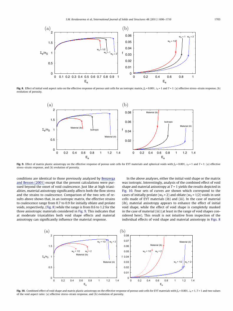
Fig. 8. Effect of initial void aspect ratio on the effective response of porous unit cells for an isotropic matrix, f0 = 0.001, k0 = 1 and T = 1: (a) effective stress–strain response, (b)evolution of porosity.
Fig. 9. Effect of matrix plastic anisotropy on the effective response of porous unit cells for EYT materials and spherical voids with f0 = 0.001, k0 = 1 and T = 1: (a) effectivestress–strain response, and (b) evolution of porosity.
S.M. Keralavarma et al. / International Journal of Solids and Structures 48 (2011) 1696–1710 1703
conditions are identical to those previously analyzed by Benzergaand Besson (2001) except that the present calculations were pur-sued beyond the onset of void coalescence. Just like at high triaxi-alities, material anisotropy significantly affects both the flow stressand the strains to coalescence. Comparison of the two sets of re-sults above shows that, in an isotropic matrix, the effective strainsto coalescence range from 0.7 to 0.9 for initially oblate and prolatevoids, respectively, (Fig. 8) while the range is from 0.6 to 1.2 for thethree anisotropic materials considered in Fig. 9. This indicates thatat moderate triaxialities both void shape effects and materialanisotropy can significantly influence the material response.
Fig. 10. Combined effect of void shape and matrix plastic anisotropy on the effective respof the void aspect ratio: (a) effective stress–strain response, and (b) evolution of porosit
In the above analyses, either the initial void shape or the matrixwas isotropic. Interestingly, analysis of the combined effect of voidshape and material anisotropy at T = 1 yields the results depicted inFig. 10. Four sets of curves are shown which correspond to thecases of initially prolate (w0 = 2) and oblate (w0 = 1/2) voids in unitcells made of EYT materials (ib) and (iii). In the case of material(ib), material anisotropy appears to enhance the effect of initialvoid shape, while the effect of void shape is completely maskedin the case of material (iii) (at least in the range of void shapes con-sidered here). This result is not intuitive from inspection of theindividual effects of void shape and material anisotropy in Figs. 8
onse of porous unit cells for EYT materials with f0 = 0.001, k0 = 1, T = 1 and two valuesy.

1704 S.M. Keralavarma et al. / International Journal of Solids and Structures 48 (2011) 1696–1710
and 9, respectively, and indicates a non-trivial coupling betweenthe two. This effect is obviously not restricted to the particular con-ditions chosen here. A similar trend was reported in Fig. 7b for amuch lower initial porosity f0 = 0.0001.
In order to further illustrate the subtle coupling between voidshape and plastic anisotropy, we examined contours of effectiveplastic strain in the matrix at a unit cell effective strain Ee = 0.5for initially prolate voids (w0 = 2) in all three EYT materials,Fig. 11. Conclusions from previous investigations of void shape ef-fects (Pardoen and Hutchinson, 2000) had indicated that materialswith more elongated voids consistently show higher ductility(slower growth of porosity with effective strain). However, furtherinvestigation reveals that the evolution of the void aspect ratio forthe three unit cells in Fig. 11 (not shown) is roughly similar up toEe = 0.5, as can be seen from the void shapes in Fig. 11. Despite thisfact, material (ib) shows greater void growth than the isotropicmatrix while material (iii) shows the least void growth at equal
Fig. 11. Contours of effective plastic strain p at Ee = 0.5 for initially prolate voids with f =
Fig. 12. An elaboration on the results of Fig. 10 for material (iii) over a wider window oeffective stress–strain response, and (b) evolution of porosity.
macroscopic strain levels. Also, the distribution of plastic strainsin the matrix is different for the three materials with material(ib) showing a greater tendency for shear localization along an in-clined band, due to its lower yield stresses in shear compared tothe other materials.
In materials with enhanced shear-resistance (category (iii)), theeffect of initial void shape is found to be negligible within the rangew0 = 1/2 to 2 (see Fig. 10 above). We have conducted additional cal-culations to explore a broader range of void shapes from w0 = 1/6to 6. The corresponding results are shown in Fig. 12 for two valuesof the initial porosity. The results show that the strains to coales-cence E(c) are not significantly changed for larger values of w0
(>2), while flatter voids (w0 = 1/6) lead to a reduction in ductility,although not to the extent expected for isotropic materials.
Next, for the same category of materials (iii) with enhancedshear resistance, we examine the conditions on the anisotropyparameters that lead to the non-trivial coupling between void
0.001, w0 = 2 and T = 1: (a) material (ib), (b) isotropic matrix, and (c) material (iii).
f initial void aspect ratios w0 for two values of initial porosity, k0 = 1 and T = 1: (a)

0
0.05
0.1
0.15
0.2
0.25
0.3
0.35
0.4
0.5 1 2
ΔE(c)
hTS
f0 = 10-4
f0 = 10-3
S.M. Keralavarma et al. / International Journal of Solids and Structures 48 (2011) 1696–1710 1705
shape and matrix flow anisotropy. The difference between an iso-tropic matrix and material (iii) lies in the values of the shear Hillcoefficients, with hTS = hSL = 0.5 for material (iii) as opposed tounity for the isotropic material (see Table 1). In Fig. 13, we contin-uously vary the values of hTS between 0.25 and 1 to observe the ef-fect on the void shape sensitivity for the coalescence strains andthe growth rate of porosity. Two values of initial void shapes,w0 = 1 and w0 = 1/2, are compared. One can see that a transitionoccurs approximately at hTS = 0.5 below which the differencebetween the curves corresponding to the two initial void shapesis negligible. Fig. 14 shows the variation of the void shape sensitiv-ity parameter DE(c), defined in Eq. (13), as a function of the Hillcoefficients hTS. The void shape sensitivity is seen to increase withincreasing hTS with an inflexion point around the isotropic value ofhTS = 1. The void shape sensitivity approaches zero for hTS < 0.5(materials of type (iii)) whereas the void shape sensitivity is seento be high for hTS > 2 (materials of type (i)).
Fig. 14. Variation of the void shape sensitivity parameter DE(c) for a wide range ofEYT materials described by the out-of-plane shear Hill coefficient hTS. Matrixmaterials with hTS < 1 are shear-resistance (type (iii)) and matrices with hTS > 1 areweak in shear (type (i)).
3.4. Case of penny shaped cracksThe limiting case of highly oblate voids or penny shaped cracksis an important one in practice. Such cracks were observed to ini-tiate in brittle phases in multi-phase materials (Pineau and Joly,1991; Bugat et al., 2001) or simply due to cracking of second phaseparticles; see the review by Benzerga and Leblond (2010). Lassanceet al. (2006) carried out a series of cell model studies of pennyshaped voids embedded in an isotropic matrix. In this section,we explore amendments to their conclusions when matrix anisot-ropy is taken into account. Attention is restricted to the same EYTmaterials investigated above. One issue with using the cell modelof Fig. 1 for particle–matrix systems is that it ignores the effectof particles. A useful result in this respect from Lassance et al.’s(2006) investigation is that particle shielding is weak for particlevolume fractions below 1% or so. We shall rely on this finding tojustify the relevance of the voided cell model to particle–matrixmaterial systems, in addition to multi-phase ones.
Three realizations of the penny-shaped crack were investigatedusing w0 = 1/30, w0 = 1/20 and w0 = 1/10 keeping the same radialvoid size to void spacing ratio (v0 = 0.247). Such initial configura-tions correspond to different values of the initial porosity but sharethe same value of the equivalent porosity f e
0 ¼ 0:01. Here, f e0 is de-
fined as the volume fraction of a spherical void having a radiusequal to that of the ‘‘crack’’. The actual porosity f0 ¼ w0f e
0 is there-fore much smaller. It was found that the response of the unit cell isweakly dependent upon the specific choice of w0 in the range con-sidered, irrespective of the type of material anisotropy. Thus, we
Fig. 13. Transition from a material (i) type behavior to a material (iii) type behavior. Effecporous unit cells with f0 = 0.001, k0 = 1 and T = 1: (a) effective stress–strain response, an
will only present results for w0 = 1/20 focussing on the effect ofmatrix anisotropy.
Fig. 15 shows the results obtained for a loading triaxiality ofT = 1 (solid lines). These results clearly indicate that the effect ofmatrix anisotropy is as significant in this limit case of pennyshaped cracks as it is for other void shapes. For instance the effec-tive strain to coalescence for material (iii) is about twice as muchas for material (ib). This effect was qualitatively expected becausethe crack quickly blunts in the matrix and opens up into a voidwith a roughly equiaxed shape.
To interpret further these results, a set of reference calculationswere carried out for the equivalent microstructure, i.e., for spheri-cal voids with f0 ¼ 0:01 ¼ f e
0 . The corresponding results are also in-cluded in Fig. 15 (dashed lines). An interesting finding in the case ofmaterial (iii) is that the response for penny shaped cracks is verydifferent from that obtained for the equivalent spherical voids. Thisputs into question the very notion of ‘‘equivalence’’. On the otherhand, it is noted that the responses for the equivalent and actualmicrostructures are indeed close to each other in the case of theisotropic matrix and material (ib). It is possible to explain why thisequivalence works well for isotropic matrices. In fact, it resultsfrom the competing effects of extremely oblate shape (negativefor ductility) and low initial porosity (positive). When the two ef-fects cancel out ‘‘equivalence’’ works. However, deviations fromthat behavior are conceivable in the presence of large deformation
t of varying the out-of-plane ‘‘shear’’ Hill coefficient, hTS, on the effective response ofd (b) evolution of porosity.

Fig. 15. Effect of matrix plastic anisotropy on the effective response of porous unit cells containing initially penny shaped cracks (w0 = 1/20) with and effective porosityf e0 ¼ 0:01 (solid lines) and spherical voids with f0 = 0.01 (dashed lines), under axisymmetric loading with T = 1: (a) effective stress–strain response, and (b) evolution of
porosity.
1706 S.M. Keralavarma et al. / International Journal of Solids and Structures 48 (2011) 1696–1710
induced microstructure evolution. Such deviations are realized inmaterials of type (iii) as shown in Fig. 15.
3.5. Materials with unequal principal yield strengths
The material anisotropy parameters used in the set of resultspresented thus far were chosen such that the materials have thesame nominal yield stresses in the three principal directions oforthotropy (hL = hT = hS = 1). As a consequence, for all such EYTmaterials the unit cell effective and mean normal stresses are ini-tially equal. Since the evolution of porosity has an exponentialdependence on the mean stress, the choice of EYT materials en-abled us to apportion the effects of material anisotropy and voidshape. However, the case of hL, hT, hS – 1 is more general and com-
Fig. 16. Effect of matrix material anisotropy on the cell model response for f0 = 0.001, kstress–strain response, (b) evolution of porosity, (c) evolution of the void aspect ratiomaterials being compared have different yield stresses in uniaxial tension along eS.
monly observed experimentally (Benzerga et al., 2004a). In thissection, we present a set of results for categories of materials withhL = hT – 1 and hS – 1.
Fig. 16a shows the comparison of stress–strain responses forunit cells made of an isotropic matrix, material (iib) and material(iv) from Table 1. Material (iib) is similar to material (ib) fromthe previous set of calculations in the sense that they both haverelatively high values of the shear Hill coefficients hTS(=hSL) com-pared to the isotropic case making them weaker under shear load-ing. On the other hand, material (iv) is weaker under tension alongthe principal directions similar to material (iii) used previously.Three different values of w0 (=1/2,1 and 2) are compared and allthe unit cells had f0 = 0.001 and k0 = 1. Each of these materialshas the same yield strengths rL = rT in the radial direction but
0 = 1, T = 1 and three values of w0. Case of non EYT materials (Table 1). (a) Effectivew; and (d) evolution of w for initially prolate cavities with w0 = 2. The anisotropic

Fig. 17. Contours of effective plastic strain p at Ee = 0.45 for non EYT materials and initially spherical voids with f = 0.001 and T = 1: (a) material (iib), (b) isotropic matrix, and(c) material (iv).
S.M. Keralavarma et al. / International Journal of Solids and Structures 48 (2011) 1696–1710 1707
the axial yield strength rS varies for each material. For comparisonpurposes, the effective stresses in Fig. 16a are normalized by theinitial yield stress, riso, of the isotropic matrix. This avoids normal-ization by a variable quantity.
One can see from Fig. 16a that material (iv) has the highesteffective strength while material (iib) has the lowest strength.Clearly, the effect of the overall stress level reflects in the evolutionof the porosity shown in Fig. 16b, where material (iv) consistentlyshows faster void growth compared to material (iib). Nevertheless,some qualitative features of the effect of the shear Hill coefficientshTS = hSL observed in the previous calculations are retained. For in-stance, the effect of the initial void shape is seen to be negligible formaterial (iv) while the effect is magnified for material (iib) (incomparison to the case of the isotropic matrix). These trends areidentical to those observed for material (iii) and material (ib),respectively, in the previous sections. One common feature ofthese results is that orthotropic materials that are weaker undershear in one of their principal planes compared to an isotropicmaterial (i.e. hTS = hSL > 1 in the transverse isotropic case) appearsto exhibit higher sensitivity to the initial void shape, while materi-als that have a high resistance to yielding under shear exhibit low-er void shape sensitivity.
Fig. 16c shows the evolution of the void aspect ratio w andFig. 16d shows the evolution of w in the w0 = 2 case with an ex-panded range for the ordinate. The interesting observation fromFig. 16d is that the mode of coalescence in the case of material(iib) appears to be different from the case of the other materials.Although the cell exhibits a transition to the uniaxial strainingmode, this is not accompanied by a corresponding drop in w asso-ciated with the rapid lateral expansion of the voids. In fact, exam-ination of the contours of effective plastic strain in the deformedconfiguration of the unit cell (Fig. 17) reveals that significant plas-tic strain has accumulated along an inclined band in the case ofmaterial (iib). This eventually leads to significant deviations froma spheroidal shape for the cavity. As a result, coalescence takesplace in a plane parallel to the equatorial plane, by necking of
the smallest deformed ligament. A more thorough investigationof the conditions under which these alternate modes of coales-cence are favored under axisymmetric loading will be providedin a forthcoming companion paper.
4. Discussion
The primary motivation for pursuing cell model studies of thetype presented in this paper is to analyze the influence of matrixmaterial anisotropy on void growth and coalescence. Previous fi-nite element cell studies have focussed on the separate effects ofvoid shape (Sovik and Thaulow, 1997; Pardoen and Hutchinson,2000; Gao and Kim, 2006) and plastic flow anisotropy in singlecrystals (Yerra et al., 2010) or textured polycrystals (Benzergaand Besson, 2001). The aim of this paper has been to assess the rel-ative importance of void shape and plastic anisotropy effects onductile fracture under a variety of triaxial proportional loadingconditions. The results of the present study also provide bench-marks for calibrating continuum models of ductile fracture inanisotropic materials. These include extensions of the Gursonmodel to incorporate additional microstructural information, suchas void shape and material texture (Gologanu et al., 1997;Benzerga and Besson, 2001; Monchiet et al., 2008; Keralavarmaand Benzerga, 2008; Keralavarma and Benzerga, 2010), as well asalternative porous metal plasticity models accounting for textureeffects in polycrystalline materials (Lebensohn et al., 2004).Furthermore, once appropriately extended to account for plasticanisotropy, the void coalescence models that were independentlydeveloped by Gologanu et al. (2001), Pardoen and Hutchinson(2000) and Benzerga (2002) can also be assessed using the presentfindings from cell model calculations.
The voided cell model is a powerful tool for investigating ductilefailure mechanisms at intermediate scales. Three kinds of parame-ters enter the model, which relate to the applied loading, themicrostructure (i.e., void population attributes) and the plastic

1 The values chosen in the text for w0, i.e., 1/2 and 2, are arbitrary. However, DEc
can be defined more objectively as the difference between infinitely long voids(cylinders) and infinitely flat voids (penny-shaped cracks).
1708 S.M. Keralavarma et al. / International Journal of Solids and Structures 48 (2011) 1696–1710
flow in the matrix. When the present results are added to the richliterature on this subject (Benzerga and Leblond, 2010), it becomesevident that the effect of matrix anisotropy is most importantamong all matrix related parameters, including strain hardening.To illustrate this, the E(c) measure of failure strain decreases bymore than 0.7 when Hill coefficient hTS varies between 0.5 and2.33 for an initial porosity of f0 = 0.001. For reference, the relativechange in failure strain is about 0.7 for the same f0 when the stresstriaxiality ratio varies between 1 and 3. The effect of matrix anisot-ropy is thus comparable to the exponential effect of triaxiality.
To understand the effect of matrix anisotropy, consider the fol-lowing combination of Hill’s coefficients
h ¼ 225
hL þ hT þ hS
hLh T þ hThS þ hShLþ 1
51
hTSþ 1
hSLþ 1
hLT
� �� �12
: ð14Þ
For an isotropic material h = 2. This scalar is an invariant of thefourth order tensor h, expressed in axes pointing toward the princi-pal directions of matrix orthotropy. It has emerged in all previousanalytical treatments of the problem at hand, or variants thereof,by means of homogenization theory (Benzerga and Besson, 2001;Monchiet et al., 2008; Keralavarma and Benzerga, 2010). Accordingto these theoretical models, the growth rate of porosity may bewritten as
_f / sinh jRh
�r
� �; ð15Þ
where Rh is a weighted mean of the normal stresses, �r is the matrixflow stress and j is a factor that depends on both void shape andmatrix anisotropy. Interestingly, j has a 1/h dependence and is ex-actly 3/h for spherical voids. The essence of the effect of matrixanisotropy on void growth is rooted in the way invariant h changesfrom one material category to another. The values taken by h, as re-ported in Table 1, correlate with the trends observed for all materi-als investigated. In particular, the exponential dependence of voidgrowth upon stress triaxiality (through Rh) and matrix anisotropy(through h) clarifies the comparable effects of T and anisotropypointed out above. Yerra et al. (2010) have also pointed out the use-fulness of Eq. (14) as a rationale for their results on void growth insingle crystals.
Our results show that the effect of matrix anisotropy is bothpersistent and subtle. The persistent effect, including at extremestress triaxialities or void shapes, is essentially explained by anaverage resistance to void growth represented by invariant h. Onthe other hand, the effect can be subtle due to varying stress levels(such as in materials with unequal yield strengths) or to strongcoupling with void shape effects. In fact, the factor j in (15) maydepend on other transversely isotropic invariants of tensor h, as in-ferred from the theoretical analysis of Keralavarma and Benzerga(2010). Such subtleties may also explain some trends discussedby Yerra et al. (2010).
We emphasize that the average resistance introduced through harises irrespective of the major load direction. Evidently, someadditional dependence upon load direction will manifest in anyanisotropic material. The analysis of any such dependence wouldrequire fully 3D calculations. The key finding is that any givenmaterial is characterized by a factor h, which sets its average resis-tance to void growth.
Among the obtained trends some findings merit further discus-sion. At high levels of remote load triaxiality (T P 2), the effect ofmaterial plastic anisotropy is a predominant factor affecting theoverall ductility, unlike the effect of void shape (Figs. 4–6). A con-tinuum model for plastically orthotropic porous materials has pre-viously been developed by Benzerga and Besson (2001) following amicromechanics based approach similar to that of Gurson (1977).It was demonstrated that this model captured well the effect of
material anisotropy on the effective response of the porous med-ium, as evidenced by comparisons of the model with unit cell cal-culations of the type presented here using initially spherical voids.Since at high T, void shape evolution has a negligible effect for ini-tially spherical cavities, the model of Benzerga and Besson (2001)neglecting void shape effects is an adequate extension of theGurson model to plastically anisotropic materials.
The behavior at moderate stress triaxialities (2/3 6 T 6 1.5) pre-vailing in notched bars can be quite different. As is now widelydocumented in the literature, void shape effects are important inthis regime. This effect is best quantified using a void shape sensi-tivity parameter, DEc, defined as the difference between strains tocoalescence for initially prolate and oblate voids.1 At high triaxial-ity, DE(c) � 0 whereas at T = 1 the difference in ductilities is alreadyabove 0.25. This figure increases further upon decreasing the triaxi-ality down to T > 1/3. For T = 1/3, void coalescence does not takeplace for f0 6 0.001, irrespective of the initial void shape (Pardoenand Hutchinson, 2000). In the regime of moderate triaxialities, thecell model studies reported on here show that the sensitivity to ini-tial void shape is influenced by matrix material anisotropy. Thisinfluence is so strong that it may either nullify the effect of voidshape (e.g. material (iii) in Fig. 10) or exacerbate it, as is the caseof materials (ib) and (iib) in Figs. 10 and 16, respectively. Typicaltrends can be summarized using the above notion of void shape sen-sitivity parameter DE(c), as shown in Fig. 7b. In this regard, Benzergaet al. (2004b) used a heuristic combination of the models byBenzerga and Besson (2001) and Gologanu et al. (1997) in theirmodeling of anisotropic fracture. For weak coupling between voidshape and matrix anisotropy effects, their heuristic combination isacceptable but the present results indicate the extent to which suchheuristics is valid.
This study does not deal with the conditions under which voidsnucleate in real materials. Any predictions made on the basis of theresults reported here would need to be augmented with detailednucleation analyses. Yet, voids are reported to nucleate at ratherlow macroscopic strain levels in various material systems (e.g., sul-fides in steels and cracks in brittle phases). In addition, when voidnucleation occurs due to brittle particle cracking, penny-shapedcracks form and blunt into the plastically flowing matrix.
Our findings for penny-shaped voids confirm that the influenceof plastic anisotropy in ductile fracture is paramount. This wasillustrated for EYT materials at a moderate triaxiality of 1 andthe same behavior is expected at higher triaxialities which pro-mote faster evolution of voids into equiaxed shapes. For all EYTmaterials that were considered, the cell model response was foundto be independent of the specific choice of the ‘‘crack’’ aspect ratioso long as w0 6 1/10. This is in agreement with the conclusions ofLassance et al. (2006) who studied the case of isotropic matrices. Asnoted there, the ductility of isotropic materials containing penny-shaped cracks is controlled by the relative void spacing. Since thelatter was kept fixed in our investigation, we conclude that matrixanisotropy is another important microstructural parameter alongwith the relative void spacing. With respect to approximating pen-ny-shaped cracks with equivalent spherical voids, our findings forsome materials support the proposition made long ago by Pineauand Joly (1991) who introduced the notion of an equivalent poros-ity f e
0 . Lassance et al. (2006) established one limitation of such anapproximation, namely the case of large particle/void volume frac-tions. The present investigation establishes another limit for mate-rials endowed with a higher resistance in shear than their isotropiccounterpart (Fig. 15). This limitation of the equivalent microstruc-ture applies at all porosity levels.

S.M. Keralavarma et al. / International Journal of Solids and Structures 48 (2011) 1696–1710 1709
Part of the effect of plastic anisotropy is associated with voidgrowth. The other part can be associated with the way in whichanisotropy affects the shift to the uniaxial straining mode, i.e.,the onset and progress of void coalescence. It is not straightforwardto apportion the two contributions from the cell model calcula-tions alone. In the absence of an analytical quantitative model ofvoid coalescence in anisotropic materials, one can document thevalues of the void volume fraction at incipient coalescence, i.e., atthe onset of micro-scale localization. Fig. 18 illustrates the trendsin terms of this ‘‘critical’’ porosity, designated f(c), versus stress tri-axiality for three EYT materials. In all the cases shown, void coales-cence took place by internal necking of the inter-void ligament.Fig. 18 illustrates that f(c) is significantly affected by the plasticanisotropy of the material and may vary as a function of the load-ing triaxiality even for an isotropic material. This finding empha-sizes a point already made in the literature, e.g., (Benzerga et al.,1999; Pardoen and Hutchinson, 2000; Gao and Kim, 2006), thatthe use of a constant f(c) in the phenomenological approach to voidcoalescence is, in general, not adequate. At the rates of void growthpreceding localization, a difference of half a percent in f(c) can leadto significant variations in the strain to coalescence E(c). What isimportant in Fig. 18 is that plastic anisotropy can lead to variationsin f(c) that are stronger than those caused by the triaxiality alone.Capturing these effects requires micromechanics based models ofvoid coalescence that take into account the cumulative effect ofthe deformation history in determining the critical conditions forthe onset of coalescence.
The computations presented here were limited to transverselyisotropic materials. Experimentally measured material anisotro-pies can be more general, and therefore the material propertiesused in this study are approximate axisymmetric representationsof the range of material anisotropies observed experimentally.Yet, the effects of material anisotropy evidenced in this work arequite prominent. This suggests that even stronger effects may beexpected in more realistic cases. The analysis of the latter wouldhowever require fully three-dimensional calculations. What is ofparticular practical importance is that plastic anisotropy effectsare significant, unavoidable (e.g., due to processing) and some-times beneficial. As such, they may prompt material designers toengineer anisotropy of certain types instead of limiting it. With thisprospect in mind, this and other concurrent modeling efforts mayhelp lay the theoretical foundations for such rational materialdesign.
0
0.005
0.01
0.015
0.02
0.025
0.03
0.035
0.04
1 1.5 2 2.5 3
f(c)
T
Material (ib)Isotropic
Material (iii)
Fig. 18. Porosity at the onset of coalescence, f(c), versus stress triaxiality ratio, T, forinitially spherical voids with f0 = 0.0001 and three EYT matrix materials.
5. Conclusions
The effect of matrix material anisotropy on void growth andcoalescence was investigated under a variety of axisymmetricloading conditions and for various initial microstructures repre-sentative of periodic void aggregates. The plastic anisotropy mod-eled here is a representation of material texture and grainelongation effects in polycrystalline materials. It can also representthe anisotropy of plastic flow in single crystals. The conclusionsdrawn from our results may be summarized as follows:
The effect of plastic anisotropy of the matrix material appears tobe a dominant factor in the mechanics of porous plastic solids,at all stress triaxiality levels. Unlike the effect of void shape,its effect does not vanish at high levels of triaxiality. In addition,at low stress triaxiality, plastic anisotropy sets the extent towhich the initial void shape affects the effective behavior ofthe porous material. The critical porosity for the onset of coalescence f(c), which gen-
erally depends on the stress triaxiality ratio, is found to dependstrongly on the plastic anisotropy of the matrix. Since void growth and coalescence are but expressions of plastic
distortion of the matrix material, the above effects of plasticanisotropy are qualitatively expected. However, the magnitudemanifested by these effects is far more significant than has beenappreciated in the literature. The computational results clearly illustrate the need for a
fundamental coupling between plastic anisotropy and voidshape effects for accurate modeling of ductile fracture in struc-tural materials. In this context, there is a need for better exper-imental characterization of the plastic flow anisotropy ofwrought structural materials under fully three-dimensionalconditions.
Acknowledgments
The authors acknowledge support from the National ScienceFoundation under grants DMR-0851828 and CMMI-0748187.
References
Barsoum, I., Faleskog, J., 2007. Rupture mechanisms in combined tension andshearG-Micromechanics. Int. J. Solids Structures 44, 5481–5498.
Benzerga, A.A., 2000. Rupture ductile des tôles anisotropes. Ph.D. Thesis, EcoleNationale Supérieure des Mines de Paris.
Benzerga, A.A., 2002. Micromechanics of coalescence in ductile fracture. J. Mech.Phys. Solids 50, 1331–1362.
Benzerga, A.A., Besson, J., 2001. Plastic potentials for anisotropic porous solids. Eur.J. Mech. 20 (3), 397–434.
Benzerga, A.A., Besson, J., Pineau, A., 1999. Coalescence-controlled anisotropicductile fracture. J. Eng. Mat. Tech. 121, 221–229.
Benzerga, A.A., Besson, J., Pineau, A., 2004a. Anisotropic ductile fracture. Part I:experiments. Acta Mater. 52, 4623–4638.
Benzerga, A.A., Besson, J., Pineau, A., 2004b. Anisotropic ductile fracture. Part II:theory. Acta Mater. 52, 4639–4650.
Benzerga, A.A., Leblond, J.B., 2010. Ductile fracture by void growth to coalescence.Adv. Appl. Mech. 44, 169–305.
Besson, J., Foerch, R., 1997. Large scale object oriented finite element code design.Comput. Methods Appl. Mech. Eng. 142, 165–187.
Bugat, S., Besson, J., Gourgues, A.F., Pineau, A., 2001. Microstructure and damageinitiation in duplex stainless steels. Mater. Sci. Eng. 317, 32–36.
Gao, X., Kim, J., 2006. Modeling of ductile fracture: Significance of void coalescence.Int. J. Solids Struct. 43, 6277–6293.
Gologanu, M., Leblond, J.-B., Devaux, J., 1993. Approximate models for ductilemetals containing non-spherical voids – case of axisymmetric prolateellipsoidal cavities. J. Mech. Phys. Solids 41 (11), 1723–1754.
Gologanu, M., Leblond, J.-B., Perrin, G., Devaux, J., 1997. Recent extensions ofGurson’s model for porous ductile metals. In: Suquet, P. (Ed.), ContinuumMicromechanics, CISM Lectures Series. Springer, New York, pp. 61–130.
Gologanu, M., Leblond, J.-B., Perrin, G., Devaux, J., 2001. Theoretical models for voidcoalescence in porous ductile solids – I: coalescence in ‘‘layers’’. Int. J. SolidsStruct. 38, 5581–5594.

1710 S.M. Keralavarma et al. / International Journal of Solids and Structures 48 (2011) 1696–1710
Gurson, A.L., 1977. Continuum theory of ductile rupture by void nucleation andgrowth: Part I– yield criteria and flow rules for porous ductile media. J. Eng.Mat. Tech. 99, 2–15.
Hill, R., 1948. A theory of yielding and plastic flow of anisotropic solids. Proc. Roy.Soc. London A 193, 281–297.
Hom, C.L., McMeeking, R.M., 1989. Void growth in elastic–plastic materials. J. Appl.Mech. 56, 309–317.
Hughes, T., Winget, J., 1980. Finite rotation effects in numerical integration of rateconstitutive equations arising in large-deformation analysis. Int. J. Numer.Methods Eng. 15, 1862–1867.
Keralavarma, S.M., Benzerga, A.A., 2008. An approximate yield criterion foranisotropic porous media. C.R. Mecanique 336, 685–692.
Keralavarma, S.M., Benzerga, A.A., 2010. A constitutive model for plasticallyanisotropic solids with non-spherical voids. J. Mech. Phys. Solids 58, 874–901.
Kim, J., Gao, X., Srivatsan, T., 2004. Modeling of void growth in ductile solids: effectsof stress triaxiality and initial porosity. Eng. Fract. Mech. 71, 379–400.
Koplik, J., Needleman, A., 1988. Void growth and coalescence in porous plasticsolids. Int. J. Solids Struct. 24 (8), 835–853.
Ladeveze, P., 1980. Sur la théorie de la plasticité en grandes déformations. Tech. Rep.9. L.M.T. Ecole Normale Supérieure, Cachan, France.
Lassance, D., Scheyvaerts, F., Pardoen, T., 2006. Growth and coalescence of penny-shaped voids in metallic alloys. Eng. Fract. Mech. 73, 1009–1034.
Lebensohn, R., Tomé, C., Maudlin, P., 2004. A selfconsistent formulation for theprediction of the anisotropic behavior of viscoplastic polycrystals with voids. J.Mech. Phys. Solids 52, 249–278.
Monchiet, V., Cazacu, O., Charkaluk, E., Kondo, D., 2008. Macroscopic yield criteriafor plastic anisotropic materials containing spheroidal voids. Int. J. Plast. 24,1158–1189.
Needleman, A., 1972. A numerical study of necking in circular cylindrical bars. J.Mech. Phys. Solids 20, 111–127.
Pardoen, T., Hutchinson, J.W., 2000. An extended model for void growth andcoalescence. J. Mech. Phys. Solids 48, 2467–2512.
Pineau, A., Joly, P., 1991. Local versus global approaches of elastic–plastic fracturemechanics. application to ferritic steels and a cast duplex stainless steel. In:Blauel, J., Schwalbe, K. (Eds.), Defect Assessment in Components –Fundamentals and Applications. ESIS, European Group on FracturePublication, pp. 381–414.
Simo, J.C., Taylor, R.L., 1985. Consistent tangent operators for rate independentelasto-plasticity. Comput. Methods Appl. Mech. Eng. 48, 101–118.
Sovik, O., Thaulow, C., 1997. Growth of spheroidal voids in elastic–plastic solids.Fatigue Fract. Eng. Mater. Struct. 20, 1731–1744.
Tvergaard, V., 1982. On localization in ductile materials containing spherical voids.Int. J. Fract. 18, 237–252.
Tvergaard, V., Needleman, A., 1984. Analysis of the cup–cone fracture in a roundtensile bar. Acta metall. 32, 157–169.
Worswick, M.J., Pick, R.J., 1990. Void growth and constitutive softening in aperiodically voided solid. J. Mech. Phys. Solids 38 (5), 601–625.
Yerra, S., Tekoglu, C., Scheyvaerts, F., Delannay, L., Houtte, P.V., Pardoen, T., 2010.Void growth and coalescence in single crystals. Int. J. Solids Struct. 47, 1016–1029.
Zhang, K.S., Bai, J.B., Francois, D., 2001. Numerical analysis of the influence of theLode parameter on void growth. Int. J. Solids Struct. 38, 5847–5856.
Copyright © 2022 FDOKUMEN