STRUCTURES OF SIMPLE SOLIDS - Alchemyst
38
- 1 - These Notes are copyright Alex Moss 2003. They may be reproduced without need for permission. www.alchemyst.f2o.org STRUCTURES OF SIMPLE SOLIDS Solids are useful for a variety of reasons. For example, Appearance – Precious and semi-precious stones of many varieties. Mechanical Properties – Metals/Alloys, e.g. Titanium for aircraft, cement/concrete (Ca 3 SiO 5 ), ceramics, lubricants (graphite), abrasives (diamond, quartz). Electrical Properties – Metallic conductors (Cu, Ag), semiconductors (GaAs), Superconductors, electrolytes (LiI in pacemaker batteries) and piezoelectrics (quartz in watches). Magnetic Properties – CrO 2 , Fe 3 O 4 in recording technology. Optical Properties – Pigments, e.g. TiO 2 , phosphors, lasers. Catalysts – Zeolites Basic Definitions Lattice – infinite array of points in space, in which each point has identical surroundings to all others. Crystal Structure – periodic arrangement of atoms in the crystal. Can be described by associating with each lattice point a group of atoms called a Motif (or Basis). • Don't mix up atoms with lattice points • Lattice points are infinitesimal points in space • Atoms are physical objects • Lattice Points do not necessarily lie at the centre of atoms
-
Upload
khangminh22 -
Category
Documents
-
view
1 -
download
0
Transcript of STRUCTURES OF SIMPLE SOLIDS - Alchemyst

- 1 -
These Notes are copyright Alex Moss 2003. They may be reproduced without need for permission. www.alchemyst.f2o.org
STRUCTURES OF SIMPLE SOLIDS Solids are useful for a variety of reasons. For example, Appearance – Precious and semi-precious stones of many varieties. Mechanical Properties – Metals/Alloys, e.g. Titanium for aircraft, cement/concrete (Ca3SiO5), ceramics, lubricants (graphite), abrasives (diamond, quartz). Electrical Properties – Metallic conductors (Cu, Ag), semiconductors (GaAs), Superconductors, electrolytes (LiI in pacemaker batteries) and piezoelectrics (quartz in watches). Magnetic Properties – CrO2, Fe3O4 in recording technology. Optical Properties – Pigments, e.g. TiO2, phosphors, lasers. Catalysts – Zeolites Basic Definitions Lattice – infinite array of points in space, in which each point has identical surroundings to all others. Crystal Structure – periodic arrangement of atoms in the crystal. Can be described by associating with each lattice point a group of atoms called a Motif (or Basis).
• Don't mix up atoms with lattice points • Lattice points are infinitesimal points in space • Atoms are physical objects • Lattice Points do not necessarily lie at the centre of atoms

- 2 -
These Notes are copyright Alex Moss 2003. They may be reproduced without need for permission. www.alchemyst.f2o.org
Unit Cell – smallest component of the crystal, which when stacked together with pure translational repetition reproduces the whole crystal. Primitive (P) unit cells contain only a single lattice point. 2D Lattices e.g. Graphite:
Counting Lattice Points – Unit cell is primitive, but contains two atoms in the motif. Atoms at the corner contribute only ¼ to unit cell count. Atoms at the edge contribute only ½ to unit cell count. Atoms within the unit cell contribute 1 to unit cell count. Analysing in 3D: Graphite = staggered arrangement of stacked hexagonal layers.

- 3 -
These Notes are copyright Alex Moss 2003. They may be reproduced without need for permission. www.alchemyst.f2o.org
Unit cell dimensions: a, b, c = unit cell lengths α, β, γ = angles (α = angle between b and c, etc.) Counting atoms in 3D: Edge contributes = ¼ Vertex contributes = 1/8 Face contributes = ½ Body contributes = 1 On combining 7 Crystal Classes with 4 possible unit cell types, symmetry indicates that only 14 3D lattice types occur. These are the Bravais Lattices. These are depicted below (note that spheres = lattice points, not atoms!)
Combining these 14 lattices with all the possible symmetry elements means there are 230 different Space Groups.
- 4 -
These Notes are copyright Alex Moss 2003. They may be reproduced without need for permission. www.alchemyst.f2o.org
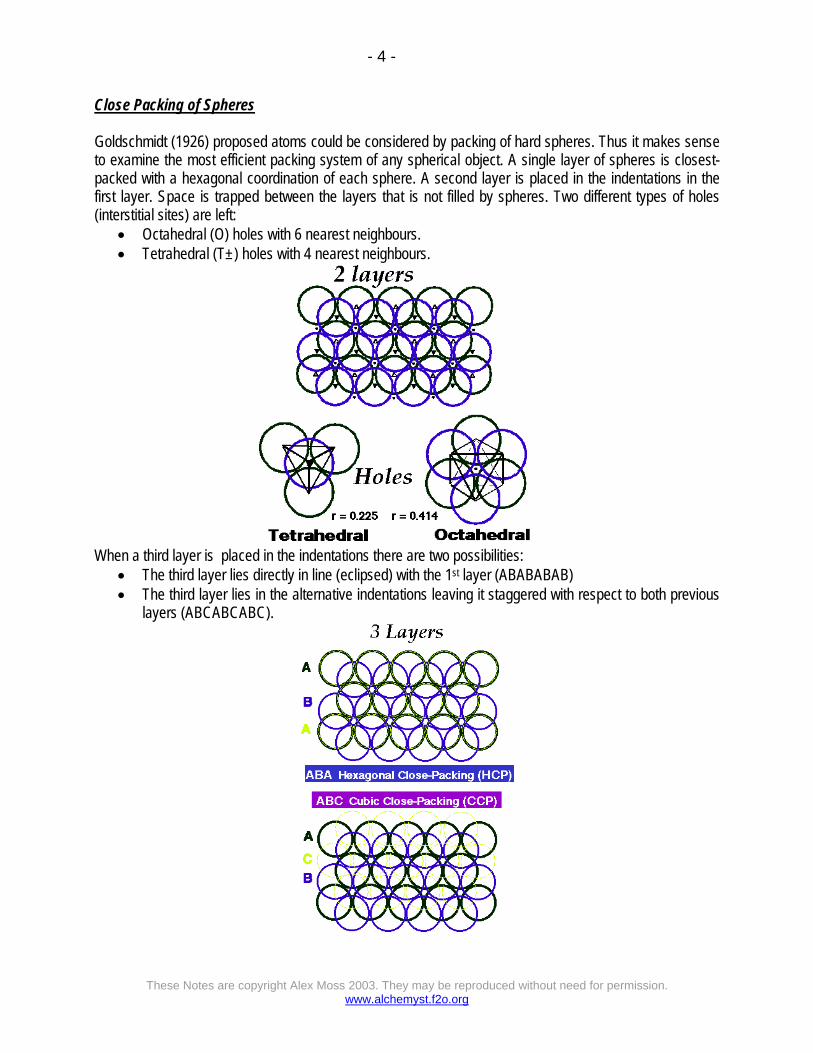
Close Packing of Spheres Goldschmidt (1926) proposed atoms could be considered by packing of hard spheres. Thus it makes sense to examine the most efficient packing system of any spherical object. A single layer of spheres is closest-packed with a hexagonal coordination of each sphere. A second layer is placed in the indentations in the first layer. Space is trapped between the layers that is not filled by spheres. Two different types of holes (interstitial sites) are left:
• Octahedral (O) holes with 6 nearest neighbours. • Tetrahedral (T±) holes with 4 nearest neighbours.
When a third layer is placed in the indentations there are two possibilities:
• The third layer lies directly in line (eclipsed) with the 1st layer (ABABABAB) • The third layer lies in the alternative indentations leaving it staggered with respect to both previous
layers (ABCABCABC).

- 5 -
These Notes are copyright Alex Moss 2003. They may be reproduced without need for permission. www.alchemyst.f2o.org
Features of Close Packing Coordination Number is 12, with 74% of space occupied
Largest interstitial sites are:
octahedral (O) ( r = 0.414) ~ 1 per sphere tetrahedral (T±) (r = 0.225) ~ 2 per sphere
Simplest Close Packing Structures: ABABAB.... repeat gives Hexagonal Close-Packing (HCP) Unit cell showing the full symmetry of the arrangement is Hexagonal Hexagonal: a = b, c = 1.63a, a = b = 90°, g = 120° 2 atoms in the unit cell: (0, 0, 0) (2/3, 1/3, 1/2) ABCABC.... repeat gives Cubic Close-Packing (CCP) Unit cell showing the full symmetry of the arrangement is Face-Centred Cubic Cubic: a = b =c, a = b = g = 90° 4 atoms in the unit cell: (0, 0, 0) (0, 1/2, 1/2) (1/2, 0, 1/2) (1/2, 1/2, 0)

- 6 -
These Notes are copyright Alex Moss 2003. They may be reproduced without need for permission. www.alchemyst.f2o.org
The most common close packed structures are metals. A non-close packed structure adopted by some is BCC:
68% of this is occupied, with coordination number of 8. Metal structures adopted:

- 7 -
These Notes are copyright Alex Moss 2003. They may be reproduced without need for permission. www.alchemyst.f2o.org
Polymorphism – Some metals exist in different structure types at ambient temperature and pressure. Many metals adopt different structures at different temperature and pressure. Different structures occur because of residual effects from atomic orbitals. It is complicated to predict structures. Best explanations for structure are based on Band Theory of Metals. BCC is clearly adopted for low number of valence electrons. In polymorphism, BCC is adopted at higher temperatures. More complex structures than simple HCP and CCP are possible. Location of Interstitial Holes in Close-Packed Structures The holes may be filled with different atoms. It is important to know how holes are displaced relative to the positions of the spheres and relative to each other. Octahedral Holes:
Tetrahedral Holes –

- 8 -
These Notes are copyright Alex Moss 2003. They may be reproduced without need for permission. www.alchemyst.f2o.org
Arrangement of Nearest Neighbours about a Sphere –
Ionic (and other) structures may be derived from the occupation of interstitial sites in close-packed arrangements:
Some binary structures derived from hole filling by one type of atom in CCP and HCP arrangements of another:
Formula Type & occupation CCP HCP
AB All octahedral NaCl Rock Salt
NiAs Nickel Arsenide
Half tetrahedral (T+ or T-)
ZnS Zinc Blende(Sphalerite)
ZnS Wurtzite
AB2 All tetrahedral Na2O Anti-Fluorite CaF2 Fluorite not known
AB3 All octahedral & tetrahedral Li3Bi not known
A2B Half octahedral (Alternate layers
full/empty) CdCl2 (Cadmium Chloride) CdI2 (Cadmium Iodide)
Half octahedral
(Ordered framework arrangement)
TiO2 (Anatase) CaCl2 TiO2 (Rutile)
A3B Third octahedral.
Alternate layers 2/3 full/empty
YCl3 BiI3

- 9 -
These Notes are copyright Alex Moss 2003. They may be reproduced without need for permission. www.alchemyst.f2o.org
Polyhedral Representations: Defining the coordination environment of an ion as a polyhedron (octahedron or tetrahedron). Can represent structures by linking polyhedra together.
STRUCTURAL TYPES Structures from Cubic Close packing NaCl (rock salt) –
• CCP Cl- with Na+ in all octahedral holes. • Lattice = FCC. • Motif = Cl at (0,0,0); Na at (1/2,0,0) • 4 NaCl in the unit cell. • Coordination 6:6 (octahedral). • Cation and anion sites are topologically identical.
CaF2 (fluorite) / Na2O (antifluorite) –

- 10 -
These Notes are copyright Alex Moss 2003. They may be reproduced without need for permission. www.alchemyst.f2o.org
• CCP Ca2+ with F- in all Tetrahedral holes • Lattice: FCC • Motif: Ca2+ at (0,0,0); 2F- at (1/4,1/4,1/4) & (3/4,3/4,3/4) • 4CaF2 in unit cell • Coordination: Ca2+ 8 (cubic) : F- 4 (tetrahedral) • In the related Anti-Fluorite structure Cation and Anion positions are reversed
ZnS (Zinc Blende) –
• CCP S2- with Zn2+ in half Tetrahedral holes (only T+ {or T-} filled) • Lattice: FCC • 4ZnS in unit cell • Motif: S at (0,0,0); Zn at (1/4,1/4,1/4) • Coordination: 4:4 (tetrahedral) • Cation and anion sites are topologically identical
Examples of Structure Adoption – NaCl –
• Very common (inc. 'ionics', 'covalents' & 'intermetallics' ) • Most alkali halides (CsCl, CsBr, CsI excepted) • Most oxides / chalcogenides of alkaline earths • Many nitrides, carbides, hydrides (e.g. ZrN, TiC, NaH)
CaF2 –
• Fluorides of large divalent cations, chlorides of Sr, Ba • Oxides of large quadrivalent cations (Zr, Hf, Ce, Th, U)

- 11 -
These Notes are copyright Alex Moss 2003. They may be reproduced without need for permission. www.alchemyst.f2o.org
Na2O –
• Oxides /chalcogenides of alkali metals
ZnS (Zinc Blende) –
• Formed from Polarizing Cations (Cu+, Ag+, Cd2+, Ga3+...) and Polarizable Anions (I-, S2-, P3-, ...); Cu(F,Cl,Br,I), AgI, Zn(S,Se,Te), Ga(P,As), Hg(S,Se,Te)
Structures Derived From Hexagonal Close Packing NiAs (Nickel Arsenide) –
• HCP As with Ni in all Octahedral holes • Lattice: Hexagonal - P • Motif: 2Ni at (0,0,0) & (0,0,1/2) 2As at (2/3,1/3,1/4) & (1/3,2/3,3/4) • 2NiAs in unit cell • Coordination: Ni 6 (octahedral) : As 6 (trigonal prismatic)

- 12 -
These Notes are copyright Alex Moss 2003. They may be reproduced without need for permission. www.alchemyst.f2o.org
ZnS (wurtzite) –
• HCP S2- with Zn2+ in half Tetrahedral holes (only T+ {or T-} filled) • Lattice: Hexagonal - P • Motif: 2S at (0,0,0) & (2/3,1/3,1/2); 2Zn at (2/3,1/3,1/8) & (0,0,5/8) • 2ZnS in unit cell • Coordination: 4:4 (tetrahedral)
Comparing Wurtzite with Zinc Blende –

- 13 -
These Notes are copyright Alex Moss 2003. They may be reproduced without need for permission. www.alchemyst.f2o.org
CdI2 (Cadmium Iodide) –

- 14 -
These Notes are copyright Alex Moss 2003. They may be reproduced without need for permission. www.alchemyst.f2o.org
HCP Iodide with Cd in octahedral holes of alternate layers.
• Lattice: Hexagonal - P • Motif: Cd at (0,0,0); 2I at (2/3,1/3,1/4) & (1/3,2/3,3/4) • 1CdI2 in unit cell • Coordination: Cd - 6 (Octahedral) : I - 3 (base pyramid)
Polyhedral representation is informative –
Examples of Structure Adoption – NiAs:
• Transition metals with chalcogens, As, Sb, Bi e.g. Ti(S,Se,Te); Cr(S,Se,Te,Sb); Ni(S,Se,Te,As,Sb,Sn)
CdI2:
• Iodides of moderately polarising cations; bromides and chlorides of strongly polarising cations; e.g. PbI2, FeBr2, VCl2
• Hydroxides of many divalent cations e.g. (Mg,Ni)(OH)2 • Di-chalcogenides of many quadrivalent cations e.g. TiS2, ZrSe2, CoTe2
CdCl2 (CCP equivalent of CdI2):
• Chlorides of moderately polarising cations e.g. MgCl2, MnCl2 • Di-sulfides of quadrivalent cations e.g. TaS2, NbS2 (CdI2 form as well) • Cs2O has the anti-cadmium chloride structure
HCP CaF2 analogue? No structures known with all tetrahedral sites filled in HCP. To explain this we note that the T+ and T- interstitial sites above and below a layer of close-packed spheres in HCP are too close to each other to tolerate the coulombic repulsion generated by filling with like-charged species.

- 15 -
These Notes are copyright Alex Moss 2003. They may be reproduced without need for permission. www.alchemyst.f2o.org
Non-close Packed Structures – Caesium Chloride:
• Lattice: Cubic - P (N.B. Primitive!) • Motif: Cl at (0,0,0); Cs at (1/2,1/2,1/2) • 1CsCl in unit cell • Coordination: 8:8 (cubic) • Adoption by chlorides, bromides and iodides of larger cations, e.g. Cs+, Tl+, NH4+
MoS2 (molybdenite) –
• Note: Hexagonal layers of S atoms are NOT Close-packed in 3D • Lattice: Hexagonal - P • Motif: 2Mo at (2/3,1/3,3/4) & (1/3,2/3,1/4) , 4I at (2/3,1/3,1/8), (2/3,1/3,3/8), (1/3,2/3,5/8) & (1/3,2/3,7/8) • 2MoS2 in unit cell • Coordination: Mo 6 (Trigonal Prismatic) : S 3 (base pyramid)

- 16 -
These Notes are copyright Alex Moss 2003. They may be reproduced without need for permission. www.alchemyst.f2o.org
Comparing MoS2 and CdI2:
Diagrams indicate that both are layer structures, with edge linked layers. However, MoS2 is linked by trigonal prisms, while CdI2 is by octahedra. Comparing MoS2 and NiAs –
• S in MoS2 / Ni in NiAs are hexagonal close-packed 2D layers • These layers do not stack in close-packed 3D sequences
o Ni layers in NiAs stack directly above each other in an AAAA... fashion o S layers in MoS2 stack in an AABBAABB ... fashion
• Two hexagonal layers directly above each other leave TRIGONAL PRISMATIC interstitials o 2 per sphere
• In NiAs, As fills half the trigonal prismatic sites between all layers of Ni, in a layer sequence bcbcbc...

- 17 -
These Notes are copyright Alex Moss 2003. They may be reproduced without need for permission. www.alchemyst.f2o.org
• In MoS2 Mo also fills alternate trigonal prismatic sites where they occur o Trigonal prismatic sites only occur between directly stacked layers (AA or BB) o Adjacent S layers with an AB sequence have no Mo inbetween & interact by van der Waals
forces • MoS2 cannot be described in terms of interstitial filling of a close-packed structure • NiAs can be described as HCP As with Ni in octahedral holes
Metal Oxide Structures Rutile, TiO2 –
• Unit Cell: Primitive Tetragonal (a = b ¹ c) • 2TiO2 per unit cell • Motif: 2Ti at (0, 0, 0); (1/2, 1 / 2, 1 /2) & 4O at ±(0.3, 0.3, 0); ±(0.8, 0.2, 1 /2) • Ti: 6 (octahedral coordination) • O: 3 (trigonal planar coordination) • TiO6 octahedra share edges in chains along c • Edge-sharing Chains are linked by vertices • Examples: oxides: MO2 (e.g. Ti, Nb, Cr, Mo, Ge, Pb, Sn), fluorides: MF2 (e.g. Mn, Fe, Co, Ni, Cu,
Zn, Pd)
Rhenium Trioxide, ReO3 –

- 18 -
These Notes are copyright Alex Moss 2003. They may be reproduced without need for permission. www.alchemyst.f2o.org
• Lattice: Primitive Cubic • 1ReO3 per unit cell • Motif: Re at (0, 0, 0); 3O at (1/2, 0, 0), (0, 1/2, 0), (0, 0, 1/2) • Re: 6 (octahedral coordination) • O: 2 (linear coordination) • ReO6 octahedra share only vertices • May be regarded as ccp oxide with 1/4 of ccp sites vacant (at centre of the cell). Defective FCC of O
atoms (a face O is missing). • Examples:
o WO3 , AlF3 , ScF3 , FeF3 , CoF3 , Sc(OH)3 (distorted)
Perovskite, CaTiO3 –
• Lattice: Primitive Cubic (idealised structure) • 1CaTiO3 per unit cell • A-Cell Motif: Ti at (0, 0, 0); Ca at (1/2, 1/2, 1/2); 3O at (1/2, 0, 0), (0, 1/2, 0), (0, 0, 1/2) • Ca 12-coordinate by O (cuboctahedral) • Ti 6-coordinate by O (octahedral) • O distorted octahedral (4xCa + 2xTi) • TiO6 octahedra share only vertices • CaO12 cuboctahedra share faces • Ca fills the vacant CCP site in ReO3, Þ a CaO3 ccp arrangement with 1/4 of octahedral holes (those
defined by 6xO) filled by Ti • Examples: NaNbO3 , BaTiO3 , CaZrO3 , YAlO3 , KMgF3 • Many undergo small distortions: e.g. BaTiO3 is ferroelectric
The perovskite structure is fully predicted by Pauling’s 2nd Rule (see below).

- 19 -
These Notes are copyright Alex Moss 2003. They may be reproduced without need for permission. www.alchemyst.f2o.org
Rationalisation of Ionic Structures Principles of Laves
1. Space Principle – space is used most efficiently. 2. Symmetry Principle – highest possible symmetry is adopted. 3. Connection Principle – there will be the most possible “connections” between components (i.e.
coordination numbers are maximised). This is followed by metals and inert gases – close-packed structures. However, deviations include BCC metals. Ionic compounds strive to follow the principles, but to an extent are modified by any specific directional bonding interactions, size differentials and stoichiometric concerns. The Ionic Model by Goldschmidt states that are ions are essentially charged, incompressible, non-polarisable spheres. More sophisticated models assume ions are composed of two parts: A central, hard, unperturbable core, where most electron density is concentrated. A soft, polarisable outer sphere, which contains very little electron density. Pauling’s Rules Structural principles for ionic crystals were summarised by Pauling in a series of Rules. They have been widely used and are still useful in many situations. Rule 1: Coordination Polyhedra A coordination polyhedron of anions is formed around every cation (and vice-versa) – it will only be stable if the cation is in contact with each of its neighbours. Ionic crystals may thus be considered as sets of linked polyhedra. The cation-anion distance is regarded as the sum of ionic radii. Valency has only an indirect bearing on coordination number, but ionic size does influence coordination number. This lead to the Radius Ratio Rules, as the coordination number of the cation will be maximised subject to the criterion of maintaining anion-cation contact. This can be determined by comparison of the ratio of r+ to r-. Limiting Radius Ratios –
Radius Ratio Coordination no. Binary (AB) Structure-type r+/r- = 1 12 none known
1 > r+/r- > 0.732 8 CsCl 0.732 > r+/r- > 0.414 6 NaCl 0.414 > r+/r- > 0.225 4 ZnS

- 20 -
These Notes are copyright Alex Moss 2003. They may be reproduced without need for permission. www.alchemyst.f2o.org
Ionic Radii scales do not generally meet at experimental electron density minima, because of polarisation of the anion by the cation. Also, ionic radii change with coordination number. Using the rules however, shows that they do not work very well. Mainly, it suggests that the CsCl structure should be adopted more often that actually happens. In fact only correct about 50% of the time – might as well guess! Reason for the failing is that structure adoption is not just due to the Goldschmidt anion-cation contact Criterion. Consider Lattice Energy – highest possible coordination number is adopted due to greater Madelung Potentials.
Structure Type Madelung Constant CsCl 1.763 NaCl 1.748
ZnS (Wurtzite) 1.641 ZnS (Zinc Blende) 1.638
Madelung Energy is seen to rise as r+/r- falls, until the structure can no longer support cation-anion contact. At the geometrically limiting radius ratio – the Madelung Energy remains constant (limit of anion-anion contact). Born-Lande –
)11(4
2
nrezNAzU
oL −=
−+
πε
A = Madelung Constant. Additional electrostatic interaction energy from 3D lattice of ions. Depends purely on structure. From this, the Kapustinskii Equation –
−+
−+
+=
rrzCvzU L
1) A/v is constant. 2) r = r+ + r- (pm) 3) average value of N = 9.
No need for the structure to be known. Good for comparisons (e.g. ionic vs. covalent character). Can work out radii from experimental UL as well. Consequences of this – CsCl is never adopted unless 8:8 coordination maximises dispersion forces. Also covalency in NaCl due to Cl- 3 p-orbitals. Note that as pressure is increased, CsCl structure is favoured. This is because high coordination number is favoured in order to put the limited volume to full use. Also it dehybridises large ions such that directional bonding effects are lost.

- 21 -
These Notes are copyright Alex Moss 2003. They may be reproduced without need for permission. www.alchemyst.f2o.org
Structure Maps show that size does matter, but the boundaries are complicated (i.e. the Radius Ratio rules are too simplistic to ever be able to rationalise). Rule 2 – Electrostatic Valence Principle (Bond Strength) In a stable ionic structure the charge on an ion is balanced by the sum of electrostatic bond strengths to the ions in its coordination polyhedron, i.e. a stable ionic structure must be arranged to preserve local electroneutrality (ions in a crystal are surrounded by ions of opposite charge so as not to produce large volumes of similar charge in the crystal - this maximizes Madelung potential!). Rule 3 – Polyhedral Linking The stability of structures with different types of polyhedral linking is:
Vertex > edge > face. Effect is largest for cations with high charge and low coordination number. Especially large when r+/r- approaches the lower limit of polyhedral stability. Sharing edges/faces brings the ions at the centre of each polyhedron closer together, hence increasing electrostatic repulsions, i.e. disposition of ions of similar charge will be such as to minimise the Electrostatic Energy between them. This rule is obeyed by compounds of high polarity (e.g. fluorides, oxides), but not those with lower polarity. Other compounds are directly contrary to it, e.g. NiAs – face-sharing stabilises due to Metal-Metal bonding. Rule 4 – Cation Evasion in mixed compounds (not Binaries) In a crystal containing different cations those of high valency and small coordination number tend not to share polyhedral elements with each other. e.g. Perovskite, CaTiO3. CaII 12 coordinate, shares FACES TiIV 6 coordinate, shares only VERTICES Rule 5 – Environmental Homogeneity The number of essentially different kinds of constituent in a crystal tends to be small, i.e. as far as possible, similar environments for chemically similar atoms. This is, however, often not obeyed. When Pauling’s Rules are not obeyed, this suggests special structural influences in the bonding.

- 22 -
These Notes are copyright Alex Moss 2003. They may be reproduced without need for permission. www.alchemyst.f2o.org
Indirect evidence for non-ionic structures are increasing polarisation in bonding, and low dimensionality (layers, chains).
Fajan’s Rules Polarisation will be increased by: 1. High charge and small size of the cation. Ionic potential Å Z+/r+ (= polarizing power) 2. High charge and large size of the anion. The polarisability of an anion is related to the deformability of its electron cloud (i.e. its "softness")

- 23 -
These Notes are copyright Alex Moss 2003. They may be reproduced without need for permission. www.alchemyst.f2o.org
3. An incomplete valence shell electron configuration. Noble gas configuration of the cation better shielding less polarizing power, i.e. charge factor in (1) should be effective nuclear charge , e.g. Hg2+ (r+ = 102 pm) is more polarising than Ca2+ (r+ = 100 pm) Bond Directionality / Extent of Covalency Electronegativity defined by Pauling as “the power of an atom in a molecule to attract electrons to itself”. Bonding type depends on the difference in electronegativity between the elements involved. Mooser-Pearson Plots combine bond directionality, size and electronegativity in Structure Maps. Beyond that, there are many other factors that influence structure adoption, particularly when looking at Transition Metal and Non-metal solids (i.e. non-ionic). Compare and contrast the crystal structures adopted by either fluorides and chlorides or oxides and sulphides of the metallic elements. Fluorides and Chlorides Fluorides tend to differ from other halides due to Fluorine’s extreme electronegativity and small size, making it much less polarisable than the others. Pauling’s scale gives an electronegativity value of 4.0 for F, the highest of any element. Hence it shows high coordination numbers (due to greater lattice energy generated) and does not form layers. This is similar for O2-. Despite this, structures for the chlorides and fluorides are often similar. This is particularly the case for the alkali metals, and is presumably due to their reluctance to occupy more complex structures due to the limited valence electron availability (they are essentially an inert core with 1 electron available for bonding/transfer). Thus they have very high ionic character for Group 1 & 2, although this does not apply for transition and post-transition metals. Hence we would expect to see the more ionic structures for the alkali metals, such as rock salt. Also, for Group 2 metals that are not very large, fluorite structures are expected (e.g. CaF2). However, moving across the periodic table sees a change in the tendencies to form these ionic structures. Typically a drop in coordination number is seen as the ionic radius falls across the periods (due to Zeff increasing as n rises but d electrons do not penetrate sufficiently to counteract it). More directional bonding results, and structures such as Zinc Sulphide and Rutile are preferred. The chlorides show a less strong ionic tendency and are larger, so it is expected that these latter structures are more likely here. For example, CaF2 is fluorite, while CaCl2 will form the rutile structure (with lower coordination) because Cl- is larger. There is also the possibility of π-donation from Cl- strengthening the bonds, but only for Transition Metals. However, when looking at the Chlorides, there are also other structures which emerge. This is because the polarisability of Cl- allows for stabilising dispersion forces to operate and other structures are thus possible (and indeed favoured). These tend to be formed from layers or chains, reflecting the increased covalency in bonding. These are typified by the CdCl2 and CdI2 layer structures (the only difference being that CdI2 is

- 24 -
These Notes are copyright Alex Moss 2003. They may be reproduced without need for permission. www.alchemyst.f2o.org
hexagonally close packed while CdCl2 is cubic). It is seen from the structure that there is significant anion-anion contact, therefore a polarisable (i.e. covalent) anion is needed to be stable. Oxides and Sulphides In a similar way to Fluorine, Oxygen differs greatly in its electronegativity and size when compared to Sulphur. Thus Fluorides and Oxides often have similar structures for the same metals, and where stoichiometries are equivalent the compounds are often isostructural. Sulphur on the other hand is large and polarisable, so we would expect to see similar trends to those observed for Chlorides, i.e. a greater significance placed on covalent interactions. Metal-Oxides bonds tend to be more ionic due to the electronegativity difference, so ionic sulphides only form with electropositive metals (i.e. Groups 1 & 2) and when the metal’s charge is low (e.g. lower than M3+, except Al2S3). When they do form, they show similarities to metal oxide structures, e.g. MnS and MnO are similar. For example, TiO2 is the classic rutile structure. Ti4+ is highly polarising, so we would expect a strong degree of covalency present. It shows O2- with 3 x trigonal planar Ti, as depicted earlier. However, TiS2 is completely different, with 3 x pyramidal bonds in layers. S2- does not exist with M4+ (non-ionic), but will instead form layers with S22- groups (disulphide ions). This does not form for Oxygen with Transition Metals, due to lone pair / lone pair repulsions from the much smaller O atoms being closer to one another. However, Oxygen will form peroxides and superoxides with large alkali metals, which are also O2 ions. Sulphur does not favour this so much, presumably preferring to catenate with several covalent bonds in a similar manner to solid sulphur (S8 units) compared to O2(g). Note that the differences in structure are sometimes so extreme that oxides may form when sulphides do not, or vice versa. For example, PbO2 forms a rutile structure (ionic), but PbS2 does not form easily (PbIV is not particularly stable – lone pair effect). In reverse, FeS2 is a stable pyrites with S2 groups as described above (based on NaCl), but FeO2 does not exist (Fe4+ is very unstable, and O does not favour covalency). Considering now the typical range of Oxides formed by most metals, the structures can usually be grouped according to stoichiometry because oxides favour the ionic model greatly, so there are less deviations. M2O (Group 1 metals) tend to be anti-fluorite structures, e.g. Na2O. This is also generally true for the sulphides because, even though sulphur does not necessarily favour ionic compounds, M+ for Group 1 is highly ionic and this overrides the covalent tendencies of S. Cs2O is an exception however, and forms an anti-CdX2 structure due to polarisability of Cs+ (unusual for a cation, but Cs+ is extremely large and therefore deformable). MO tend to form rock salt structures (particularly for Group 2 metals) or ZnS structures when the metal is smaller and sterics become important (ZnS structures are 4 coordinate instead of 6). ZnS is also favoured by Transition Metals because there is a higher degree of dispersion forces in effect, and this is stabilising when there is more polarisation (which is suitable for Transition Metals because of their higher valence electron count). There is no metal oxide with the NiAs structure due to the high Madelung Constant for O (too ionic).

- 25 -
These Notes are copyright Alex Moss 2003. They may be reproduced without need for permission. www.alchemyst.f2o.org
Comparison with the sulphides shows great variety, particularly for the Transition Metals, e.g. CuO (zinc blende) compared to CuS (unusually complicated), and FeO, NiO, CoO favouring rock salt structure while FeS and CoS forming Nickel Arsenide structure (i.e. more metal-metal bonding and generally greater dispersion forces in operation due to face-sharing). NiS is in fact 5:5 coordinate, and bears no resemblance to the above. In fact, many transition metal sulphides resemble alloys in their structures. Structures can also be temperature dependent, e.g. NiO has the rock salt structure at high T but lowers symmetry at low temperatures. Note that CuO, AgO, PdO and PtO are not typical metal oxide structures, but in fact are isostructural with their MS counterparts. They tend to favour directional bonding (either collinear or planar depending on their d electron counts and hybridisation). MO2 compounds favour fluorite and rutile structures (i.e. ionic). MO3 is typically the Rhenium Trioxide structure. This is very similar for the fluorides, emphasising the likeness of their structural chemistry. These structures do tend to distort, particularly for large metals such as 2nd/3rd row TM’s. M2O3 is usually based on the corundrum structure, although there are exceptions, such as Mn2O3 (see later on). M3O4 is a little rarer, and often forms the spinel structures. These can be normal spinels, as in MgAl2O4, or inverse spinels (energetically less favoured unless there are particularly significant Crystal Field Stabilisation Energies in effect). Sulphides, as expected, favour layered structures more so than the metal oxides above. Some examples are:
• TiS2 (CdI2 structure). • TaS2 (CdCl2 structure). • MoS2 .
In what ways do the compounds of transition and post-transition metals embraced by your choice show special features in their structures? Considering the effect of the metal on these structures involves separating the periodic table up into essentially 3 Groups. Alkali metals from Groups 1 & 2 are the simplest to discuss, because they are essentially ionic and so structure adoption is usually governed by maximising coordination number (electrostatic lattice energy is largest when there are more bonds) while at the same time reducing steric repulsion (which acts to counteract the energy gained from bond formation). This allows their structures to be predicted more easily, particularly as their radii increase steadily down the groups. This actually explains why the fluorides and oxides tend to show the same structures – the ionic model is working. Transition Metals and post-Transition Metals can also be grouped separately, although there are more factors to consider here, including the ones for alkali metals above. Considering firstly the Transition Metals, it is known that there are often many valence d-electrons present, as opposed to a hard central core of electrons as seen for the alkali metals. These d-electrons are capable

- 26 -
These Notes are copyright Alex Moss 2003. They may be reproduced without need for permission. www.alchemyst.f2o.org
of affecting structure in a number of ways, due to the way that the orbitals split in energy when a ligand (anion) approaches them. The splitting corresponds to a Ligand Field Stabilisation Energy (the difference between the orbitals raised and lowered in energy). This has many effects:
1) Ordering of orbitals. The most obvious example here is d8 ions, which show a strong preference for square planar conformation (i.e. coplanarity in crystal structure). Classic examples of this are 2nd/3rd row metals with d8 such as Pt(II) and Au(III), where the splitting is larger for their 5d orbitals and so the stabilisation energy gained for them is greater (so more favoured). More detail on this in the Questions below.
2) Jahn-Teller Effects. This comes about in order to lift the degeneracy of the orbitals, and involves a geometric change so that bond lengths are not equivalent (i.e. the energies of the orbitals differ so they are non-degenerate). This is particularly seen for d4 and d9 ions because it is the eg set that is degenerate, and this has anti-bonding character and therefore shows a greater change in bond length than the non-bonding t2g. Usually 4+2 geometry is seen, as the two axial bonds length (more on this later).
3) d10 ions are particularly unusual in that they form linear structures. This is for a number of reasons, namely: spd hybridisation (2nd order Jahn-Teller effect), smaller size at this end of the Transition Metals (not as electron deficient) and also that with 10 electrons already, less ligands are needed to reach a stabilised complex with most of its orbitals filled (typically 18 electrons is taken as stable as it is just before any anti-bonding orbitals are occupied).
4) Spinels. The structures of spinels is often dependent on CFSE as to whether or not the inverse structure is adopted (more on this later).
5) Metal-Metal bonding. This is common in the Transition Metal series because there are plenty of valence d-electrons available to do this, and it is obviously going to affect structure as the two metal atoms are going to have to be close to each other in order to effectively bond. A good example of this is the nickel arsenide structure, where face-sharing polyhedra allow for M-M interactions (this is particularly seen later in the Transition Series).
6) Multiple bonding and cluster compounds. These are also common, particularly for 2nd/3rd row transition metals where low oxidation states are unfavourable so metal-metal multiple bonds and bridging ligands help to stabilise. This leads to unusual structures, e.g. ReCl3 (see later).
Considering now the post-transition metals, many of the above effects are observed, although not now due to ligand field effects (as the d orbitals are filled). Instead there is directional / covalent bonding seen due to the properties of the elements themselves (i.e. large and soft) and the lack of unpaired electrons. This leads to essentially molecular solids in some cases, e.g. HgCl2 which is made up of linear molecules (d10 again) which arrange neatly into solids (see later). The greater covalency means that lower coordination numbers are more common. The post-transition metals are also less discriminatory when comparing O/F vs. S/Cl. Further effects noted here are due to trends in the p-block elements. The alternation effect has many consequences (that is the fact that radii vary as pairs because of contraction via filled d-orbitals / f-orbitals which don’t shield effectively). Similarly the inert pair effect is also very significant as it leads to mixed valence compounds. For example, Pb(III) is not a stable oxidation state, so Pb3O4 is in fact made up of Pb(II) and Pb(IV) (not the spinel structure of +2 and +3). There is also the possibility of M-M bonding again (e.g. GaII compounds such as GaS – see later) and lone pair effects which can be considered using VSEPR Theory (Sn(II) and Te(IV) – see later).

- 27 -
These Notes are copyright Alex Moss 2003. They may be reproduced without need for permission. www.alchemyst.f2o.org
Worth of note is that due to the irregularities in structure showed by the Transition Metals and post-Transition Metals, there are often useful properties that arise from these defects. For example, this can lead to special properties such as semiconductivity (ZnO, NiO, PbS), superconductivity (mixed phase Cu Oxides with varying stoichiometries), bright colours (CdS – yellow, CuS – blue) and magnetism (e.g. GaS is a diamagnet, yet would be expected to have an unpaired electron). What factors influence the structure adoption by Halides?
• Divide into F (ionic) and rest of X (greater covalency) and why. • Typical structures adopted by F:
Rock salt. Fluorite. ReO3.
• Structures more common to other X: Rutile. CdCl2/CdI2. CsCl (and effect of increased pressure).
• Factors affecting adoption. • Laves – Space, Symmetry, Connection. • Pauling’s Rules.
1. Contact Polyhedra. Radius Ratio and Madelung. 2. Electroneutrality. 3. Linking Polyhedra (V > E > F). F- obeys this.
• But, often not the case: Polarisability (Fajan’s Rules).
• For varying M, also consider: Pre-TM – highly ionic. Overrides covalency. Size vs. Charge. TM – d-configs (J-T, d10, d8) leads to distortions. M-M and clusters. Directionality. Post-TM – mixed valence and lone pairs. Directionality.
• Defects What factors influence the structure adoption by oxides and sulphides?
• Similar to Halides above. • O vs. S – differences. • O-structures – NaCl, CaF2, TiO2, ReO3, M2O, M2O3, M3O4. • S-structures – layers, chains, CdCl2/I2, FeS2, NiAs, ZnS, MoS2, etc. • Rationalise – Laves / Pauling / Fajan’s. • Also M-effects:
Pre-TM – highly ionic. Overrides covalency. Size vs. Charge. TM – d-configs (J-T, d10, d8) leads to distortions. M-M and clusters. Directionality. Post-TM – mixed valence and lone pairs. Directionality.
Coplanar 4 Coordination – This is comparatively unusual in the first Transition Series. This is because of steric considerations – it is more favourable to place the 4 ligands equally separated around the central metal atom to reduce steric repulsions and maximise coordination geometry (tetrahedral).

- 28 -
These Notes are copyright Alex Moss 2003. They may be reproduced without need for permission. www.alchemyst.f2o.org
However, there are sometimes cases where other factors override these advantages, and coplanarity is observed due to directive bonding. For example, in [Ni(CN)4]2-, the Ni2+ metal possesses 8 d-electrons. Also, CN- is a strong field ligand. This gives rise to a high splitting parameter such that it is actually energetically advantageous to place the ligands in a square planar configuration, because the stabilisation energy gained from lowering the energy of the non-bonding orbitals and the fact that the orbitals destabilised (raised in energy) are not occupied when there are 8 d-electrons leads to a favourable configuration. A different case is that for Cu(acac)2, where Cu(II) has 9 d-electrons. We might expect here for 3 acac (bidentate) ligands to bind to the Cu octahedrally, but in fact d9 shows Jahn-Teller degeneracy in the eg orbitals for the Oh splitting arrangement. Thus the molecule seeks to lift this degeneracy by stretching the equatorial ligand bonds and compressing the axial ones (see diagram). This would normally give rise to a distorted octahedral arrangement, but in this case the bidentate ligands are stretched too much, such that the axially bound ligand cannot remain attached (acac is not particularly flexible due to resonance between the two O atoms reducing is freedom to rotate). This is also seen for the Cr(acac)2 example, where Cr(II) has 4 d-electrons which also show the eg degeneracy.
Another example of d8 complexes is Fe(dmpe)2, where Fe(0) has 8 electrons and this very low oxidation state is stabilised by 2 chelating ligands surrounding the iron in a plane (the dmpe is also a strong σ-donor and so can stabilise the D4h orbital configuration). Note here that again there is a chelating ligand, which presumably cannot fit round to bind axially (although no Jahn-Teller distortions this time), meaning that the square planar arrangement is the most stable. Linear Coordination – Elements such as Au, Ag and Cu in particular show a tendency to favour directional bonding (covalency) which gives rise to collinear bonding as seen in 2-coordination compounds. In fact, for this group, Au favours this more so than Ag, which in turn favours it more than Cu, and this provides a clue to the explanation for it. Firstly, all the elements mentioned are d10 (i.e. +1 oxidation state). This means that there are always electrons going to be present in anti-bonding orbitals when ligands are present. This is particularly the case for 2nd/3rd row metals, as the d-orbitals are larger so antibonding electrons are more destabilising (“in the way” more). M-L bonds are still desirable, but to minimise the anti-bonding destabilisation the orbitals hybridise (spd – s & p mix in with d), which aligns the orbitals in a linear fashion and is favourable for low energy orbitals. The large number of valence electrons and the highly covalent bonding outweighs the

- 29 -
These Notes are copyright Alex Moss 2003. They may be reproduced without need for permission. www.alchemyst.f2o.org
tradition “more coordinate ligands the better” electrostatic argument. It also allows for 2nd order Jahn-Teller effects (i.e. linear). Secondly, down the group, the directive bonding is further enhanced by relativistic contraction (which depends on n) such that for Au(I) 6s orbitals contract while 5d expand. This favours the spd hybridisation and covalency further, such that a greater majority of Au(I) complexes are linear compared to e.g. Cu(I). Also, more simply, down the group there is easier mixing (s is lower in energy while d is increased). 2nd and 3rd row metals compared to 1st row – 2nd and 3rd row Transition Metals are likely to have very different structures from the 1st row due to the better overlap and greater size of their valence d orbitals. This has been discussed in previous tutorials. This gives rise to cluster compounds (particularly to stabilise low oxidation states which are not favoured). Generally it gives rise to more Metal-Metal bonding, so that structures distort to accommodate this, as is happening here for ReCl4- (quadruple Re-Re bond) and MoCl42- (cluster). Spinels – Spinels have already been discussed in the context of CFSE and electrostatic considerations. Here it is simply a case of explaining why normal/inverse structures are adopted for these compounds: MnFe2O4 is going to show a unanimously 0 CFSE for all the metal ions because they are all d5, so it is expected to behave much like spinel itself, and adopt the normal structure because this is electrostatically and sterically favoured (by calculation) – i.e. there’s no preference for either Tetrahedral or Octahedral for any of the ions, much like spinel itself. MgFe2O4 also shows no preference by CFSE calculation (Mg has no d electrons and Fe3+ is d5). However, the inverse spinel structure is adopted, which contradicts the above. This can be explained by noting that Mg2+ has a very high charge to size ratio, and this is likely to favour Octahedral coordination. Thus, Mg2+ will favour being in the B site, while Fe shows no preference, and so the inverse structure is adopted. TiFe2O4 is similar to MgFe2O4 once you account for the fact that is likely to be Ti4+ Fe2+2 O4. This is because Ti2+ would certainly reduce Fe3+. Thus it becomes an issue of size to charge ratio as for Mg – Octahedral coordination dominants over the CFSE of Fe2+ and it is inverse. has its structure determined by the Ti ion, since Fe again is d5 and has no preference. Ti2+ has a CFSE of 4/5 in Octahedral environment and 6/5 in Tetrahedral, so we might expect a normal structure. However, D depends on environment as well, such that it is 4/9 as large when in tetrahedral. Thus 4/5 is larger than 6/5 x 4/9, so octahedral environment is preferred by Ti2+ by CFSE calculation. For NiAl2O4, the d8 ion is also biased towards Octahedral (it is the reverse of d2, so CFSE of 6/5 for Oh and 4/5 for Td). Al3+ will have no preference due to a lack of d-electrons again, so inverse is favoured. Thus it overrides any charge preferences. For NiMn2O4, there are no d5 or d0 ions, so a thorough examination is required. It turns out that inverse is again favoured, presumably due to the strong Oh preference of Ni2+ again. The CFSE calculation gives 2.87 for inverse and only 2.156 for normal, so there is greater stabilisation in the inverse form.

- 30 -
These Notes are copyright Alex Moss 2003. They may be reproduced without need for permission. www.alchemyst.f2o.org
Post-Transition Metals – Ga has been discussed earlier. Ga forms atom pairs in the solid state (i.e. M-M bonds) in a similar fashion to I2. This then arranges into layers, as does I2, and presumably conducts when compressed in a similar fashion. The stability of the +2 oxidation state is unusual because Ga is in Group 3 (+1 and +3 would be expected due to the inert pair effect). This stability again arises because of Ga-Ga bonding effects, e.g. as in GaS where each Ga coordinates to 3S and 1Ga (diagram shown earlier). This gives a layer structure again – a sure sign that covalency is in operation. It has also been proved as the compound is diamagnetic (i.e. the spare unpaired electron is taken up in a Ga-Ga bond). Lone Pair Effects – Both Sn(II) and Te(IV) possess a lone pair which influences the geometry (since anions do not want to be near to it due to electrostatic repulsion). Thus it is often seen that e.g. for SnO layered structures form, with 4 O anions arranged in a square to one side of the Sn, which can be viewed as essentially a square based pyramid arrangement:
This is also seen for TeO2. Other examples are: Sn(C5H5)2, see a bent metallocene-like structure:
Hence there is an electric dipole in operation here because the molecule is no longer linear and the Sn bonds are polarised. SnCl2 will not form aligned regular structures, but place the Cl anions to one side, away from the lone pair. This gives rise to irregularities in the gross structure, and so an electric dipole develops in the same way as above.

- 31 -
These Notes are copyright Alex Moss 2003. They may be reproduced without need for permission. www.alchemyst.f2o.org
Topological Approach to Structure – Networks Concept of connectedness (P) of a network connecting structural units (atoms or groups), e.g. structures of non-metallic elements P = 8 – N The “8-N Rule”. P = 1, e.g. iodine dimers Iodine dehybridises to a metallic FCC state at high pressure.
P = 2, e.g. S8 rings
Note how the packing approximates to a distorted close-packing arrangement. Apparently 11 coordinate (3 left + 5 in-plane + 3 right). P = 2, e.g. α-Se chains

- 32 -
These Notes are copyright Alex Moss 2003. They may be reproduced without need for permission. www.alchemyst.f2o.org
P = 3, e.g. As layers
Carbon allotropes with P = 3 (layers and cages)
Carbon with P = 4 is diamond
This is the commonest P = 4 network. It has very high (cubic) symmetry. Consider,

- 33 -
These Notes are copyright Alex Moss 2003. They may be reproduced without need for permission. www.alchemyst.f2o.org
Some Common Structures
BaO NaCl – optimal CN for ionic compound. Be2+ is the only exception for MO in Group II MoS2 Trigonal prismatic, D3h ligand field splitting for d2 compound, and highly covalent layered
structure. FeS2 Pyrites (NaCl-like) & marcasite (rutile-like). S22- groups – highly ionic. Na2S Antifluorite structure. GaCl2 Ga+(GaCl4)- fused salt. GaIGaIII mixed valence. PCl5 Gaseous trigonal bipyramidal, but PCl4+PCl6- crystal similar to GaCl2 TiS2 CdI2 polarising Ti4+
GaCl3 Dimer to Ga2Cl6. 4-coordinate molecular. PBr5 PBr4+Br-. Heat dissociated. TlI Normal (yellow) layered. 5 nearest to Tl apices of Oh. Displaced slices of NaCl (NaOH
structure). Also a red form (CsCl). BeF2 Cristobalite (4:2). MgF2 Rutile. CaCl2 Rutile (distorted). HgCl2 Molecular solid (linear). PdCl2 Chains of [PdCl4]. CrCl2 d4 distorted Oh (Jahn-Teller). MoCl2 M-M cluster (Mo6Cl84+ units). LaCl3 UCl3 (9 coordinate). Ionic. V2O5 Layered vanadate VV (tetrahedral coordinate). Cu2O Lower CN than antifluorite.
γ-Al2O3 Defect spinel. Mn2O3 C-rare-earth sesquioxide (similar to CaF2). MoO2 Distorted rutile.
Examples, Comparisons and Anomalies
Compare MnO2, SbO2, CeO2 – MnO2 is not the most stable manganese oxide, and has many polymorphs and shows non-stoichiometry. The β-MnO2 form has true stoichiometry and has the rutile structure (good Madelung Constant). This is 6:3 coordinate, and allows for some M-O π-bonding via the trigonal planar arrangement to occur (typical for Transition Metals). SbO2 is unusual in that antimony would not be expected to exist in the +4 oxidation state. In fact it is Sb2O4 and mixed valence (Sb(III) and Sb(V)). This is apparent from the inert pair effect seen on moving down most of the p-block Groups. Its structure is octahedral coordination by O, and forms corrugated sheets of distorted SbVO6 octahedra (no lone pair) which vertex share, with SbIII lying in between the layers (irregular 4-coordinate, due to lone pair tending to force pyramidal structure). CeO2 is expected to have the fluorite structure, due to the very large and highly ionic Ce4+ ion allowing easy coordination of 8 anions. This is energetically preferable to coordinating only 6 (as in the rutile structure). HCP arrangement is unlikely due to the repulsions between the close tetrahedral holes when face sharing (it edge shares instead).

- 34 -
These Notes are copyright Alex Moss 2003. They may be reproduced without need for permission. www.alchemyst.f2o.org
Compare AlCl3, ReCl3, AuCl3 – AlCl3 has a distorted CrCl3 structure, which is layered. It is not molecular like Al2Br6. It looks something like:
AuCl3 on the other hand is molecular like Al2Br6, forming the same kind of dimer:
This is because planarity is greatly favoured for Au(III) ions on account of having 8 d electrons. When they are 2nd/3rd row, the splitting parameter (∆) is larger so allows for D4h orbital splitting. This is energetically favourable for d8 when ∆ is large enough to pair electrons in dz2. ReCl3 is in fact made up of trimeric units (continuing the trend), forming essentially a planar hexagonal network with Re-Re bonding extensive (and contributes greatly to why this structure is adopted). ReIIICl3, despite being d4, is in fact diamagnetic showing possibly quadruple bonding occurring.
Compare CaS, NiS, GaS – CaS has the NaCl structure due to the large size of Ca2+.
- 35 -
These Notes are copyright Alex Moss 2003. They may be reproduced without need for permission. www.alchemyst.f2o.org
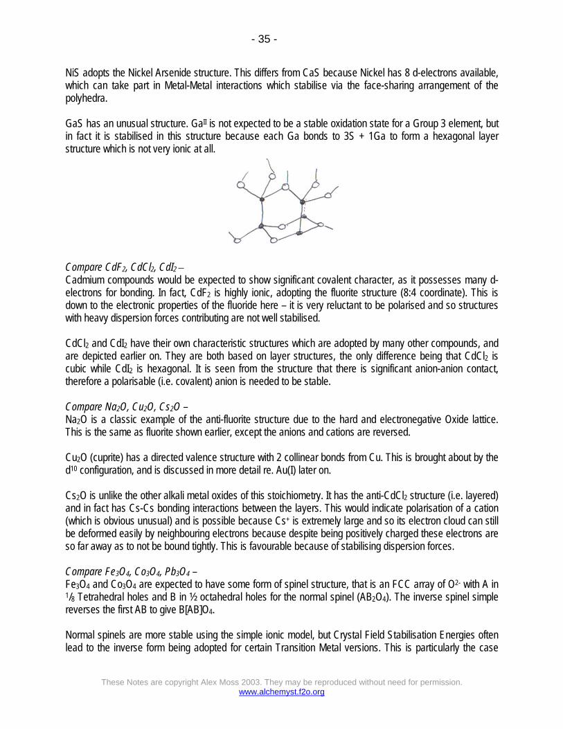
NiS adopts the Nickel Arsenide structure. This differs from CaS because Nickel has 8 d-electrons available, which can take part in Metal-Metal interactions which stabilise via the face-sharing arrangement of the polyhedra. GaS has an unusual structure. GaII is not expected to be a stable oxidation state for a Group 3 element, but in fact it is stabilised in this structure because each Ga bonds to 3S + 1Ga to form a hexagonal layer structure which is not very ionic at all.
Compare CdF2, CdCl2, CdI2 – Cadmium compounds would be expected to show significant covalent character, as it possesses many d-electrons for bonding. In fact, CdF2 is highly ionic, adopting the fluorite structure (8:4 coordinate). This is down to the electronic properties of the fluoride here – it is very reluctant to be polarised and so structures with heavy dispersion forces contributing are not well stabilised. CdCl2 and CdI2 have their own characteristic structures which are adopted by many other compounds, and are depicted earlier on. They are both based on layer structures, the only difference being that CdCl2 is cubic while CdI2 is hexagonal. It is seen from the structure that there is significant anion-anion contact, therefore a polarisable (i.e. covalent) anion is needed to be stable. Compare Na2O, Cu2O, Cs2O – Na2O is a classic example of the anti-fluorite structure due to the hard and electronegative Oxide lattice. This is the same as fluorite shown earlier, except the anions and cations are reversed. Cu2O (cuprite) has a directed valence structure with 2 collinear bonds from Cu. This is brought about by the d10 configuration, and is discussed in more detail re. Au(I) later on. Cs2O is unlike the other alkali metal oxides of this stoichiometry. It has the anti-CdCl2 structure (i.e. layered) and in fact has Cs-Cs bonding interactions between the layers. This would indicate polarisation of a cation (which is obvious unusual) and is possible because Cs+ is extremely large and so its electron cloud can still be deformed easily by neighbouring electrons because despite being positively charged these electrons are so far away as to not be bound tightly. This is favourable because of stabilising dispersion forces. Compare Fe3O4, Co3O4, Pb3O4 – Fe3O4 and Co3O4 are expected to have some form of spinel structure, that is an FCC array of O2- with A in 1/8 Tetrahedral holes and B in ½ octahedral holes for the normal spinel (AB2O4). The inverse spinel simple reverses the first AB to give B[AB]O4. Normal spinels are more stable using the simple ionic model, but Crystal Field Stabilisation Energies often lead to the inverse form being adopted for certain Transition Metal versions. This is particularly the case

- 36 -
These Notes are copyright Alex Moss 2003. They may be reproduced without need for permission. www.alchemyst.f2o.org
when d5 ions such as Fe3+ and Mn2+ are present, as these have CFSE = 0 and so show no particular preference for position. Hence, we would expect Fe3O4 to be an inverse spinel, while Co3O4 to be normal (it is d6/d7 only). Pb3O4 (or Red Lead) is not called a spinel at all, although it is in fact isostructural with Fe3O4. It is mixed valence due to the inert pair effect (i.e. no Pb(III) stability compared to Pb(II) and Pb(IV)). Edge sharing chains of PbIVO6 octahedra result, and these are then linked by the remaining PbII (distorted due to Pb(II) lone pair). Compare MgO and AgO – MgO is a typical rock salt structure, on account of the very small Mg2+ ion and also the hard O2- leading to a predominantly ionic interaction where coordination number can be maximised. AgO on the other hand is completely different. This is because it is in fact mixed valence – Ag(I) and Ag(III). This leads to both square planar and linear tendencies due to directional bonding effects as discussed earlier. Compare MgF2 and CrF2 – MgF2, in a similar argument to MgO, strongly favours ionic 3D structures. In this case rutile is likely to be preferred because Mg2+ is very small and so steric factors are likely to prevent coordinating 8 Fluoride ions in an energetically favourable way. CrF2 adopts a similar rutile structure, but there is a distorted nature to it. This can easily be explained by considering that Cr(II) has 4 d-electrons, and so is also likely to undergo Jahn-Teller distortions (discussed earlier). The effect of this is to distort the 6 coordinated fluoride anions so that the axially positioned ones have longer Cr-F bonds than those equatorial, giving rise to a 4+2 pattern for coordination (which is obviously going to distort from the typical rutile). Compare SrO and PbO – SrO is a typical rock salt structure which is seen by many monoxides with larger metal ions. This is to allow for greater dispersion forces in operation and reduce unfavourable Sr-Sr interactions present in the rock salt structure. PbO actually has 2 polymorphic forms, one based on tetragonal and the other on rhombic. They form layers and chains respectively, showing that for PbII there is a much greater tendency for dispersion forces to operate to stabilise structures that are less pure ionic forms. Also there is the lone pair present which leads to the distorted structures. Compare BaCl2 and HgCl2 – BaCl2 adopts a structure similar to PbCl2, where Ba coordinates 9 Cl- ligands (6 at the apices of a trigonal prism, with 3 face-centred on that prism). This reflects the great size of Ba2+ such that it will coordinate as many ligands as possible to gain lattice energy from forming more M-L bonds. HgCl2 is however completely different. It is essentially molecular (linear Cl-Hg-Cl molecules) although these will arrange neatly like so:

- 37 -
These Notes are copyright Alex Moss 2003. They may be reproduced without need for permission. www.alchemyst.f2o.org
This reflects a very covalent bond, which is not surprising for mercury(II) (d10) which also explains why it is linear (spd hybridisation as for Au(I) discussed earlier). Compare KCl and CuCl – KCl is a typical rock salt structure, as for most of the alkali metal halides where the ionic model applies. CuCl on the other hand favours the zinc blende structure where tetrahedral coordination is present (Cu+ is much smaller than K+ due to the non-penetrating d-orbitals being full), and more importantly that there is a greater covalent character to accommodate the soft nature of Cu(I). Compare a-Al2O3, g-Al2O3 & Mn2O3 – α-Al2O3 forms the classic corundrum structure typical for this stoichiometry of oxide. The γ-Al2O3 form is however less compacted and forms a wide variety of phases. Mn2O3 is particularly unusual though, and forms a “C” rare-earth sesquioxide which is not like corundrum. It is still 6 coordinate about Mn, but adopts the 4+2 geometry as seen earlier because of Jahn-Teller distortions in d4 Mn(III). Compare MgO, TiO & NbO – All 3 of these compounds MgO, TiO and NbO form the rock salt structure. However, the transition metal versions show defects in their structure. TiO shows Schottky defects (vacancies) and also forms a variety of non-stoichiometric phases, while NbO has its own characteristic structure where there are many vacancies – the central O atom is not present, and each of the corners of the unit cell (Nb) is also absent. Compare ZnO, PdO & PbO – ZnO forms the wurtzite structure, while the other two compounds vary greatly. PbO forms 2 polymorphs (one layered and one chain) as mentioned earlier. PdO favours 4 coplanar bonds, which is not surprising as it is a d8 2nd row Transition Metal, so will favour square planar conformations as discussed. Compare TiO2, ZrO2 & MoO2 – TiO2 is the classic rutile structure. MoO2 is expected to also adopt the rutile, but it distorts quite extensively to try to maximise M-M bonding interactions which are favoured for the larger TM’s. ZrO2 in fact forms the fluorite structure at high temperatures, indicating a preference for 8 coordinate geometry (presumably reflecting its greater size compared to both its Ti and Mo neighbours). At lower temperatures though a monoclinic structure is adopted, which is 7 coordinate, so presumably it is somewhere around the threshold between many ligands being electrostatically favourable but also leading to repulsive steric effects when too crowded.

- 38 -
These Notes are copyright Alex Moss 2003. They may be reproduced without need for permission. www.alchemyst.f2o.org
Layered Oxides – Compare NaCrO2, NaMnO2, α-FeO2 and NaCuO2. All have the layered rock-salt structure (the α-NaFeO2 structure) which is also exhibited by the important battery metal LiCoO2.
In NaCrO2 and NaFeO2 both cations are in regular trigonal antiprismatic (close to octahedral coordination). NaCuO2 contains CuIII d8 which adopts square planar coordination. MnIII d4 shows a large Jahn-Teller distortion due to degeneracy in the antibonding eg
orbitals, and the Mn coordination environment consists of four oxide neighbours, + 2 slightly further away. Partial deintercalation of sodium from NaFeO2 to produce NaxFeO2 (x<1) results in some oxidation of FeIII to FeIV d4, and the resulting Jahn-Teller distortion reduces the symmetry of the Na-deficient material.
Linear Coordination – d10 ions such as CuI, AgI, HgII often adopt linear coordination. For example in the delafossite structure of CuFeO2 which contains Cu(I) and Fe(III):