Failure of inelastic solids
30
L.V. Nikitin and Sh.A Mukhamediev 4 Failure of inelastic solids 4.1 Introduction Solids can fail mechanically under the action of external forces. Two extreme types of failure behavior are brittle fracture, when a solid breaks without substantial permanent deformation, and viscous rupture, where at least one of the dimensions of the solid is very small. The former is frequently associated with a tensile mode and latter with a shear mode with plastic deformation. In practice, failure may contain both of the foregoing types - i.e., mixed failure mode - and the behavior applies to a specimen or structure. A structure can lose its load carrying capacity if it is deformed excessively without load increase before or at the same time as complete failure. Instability of geometric or rheological nature, unstable damage accumulation or subcritical crack growth can precede the full loss of structural integrity; these events can also occur simultaneously. The thresholds of global failure can be referred to as the critical states that involve various types of instability and/or loss of load bearing capacity and/or crack growth. Deformation in the subcritical states may be elastic or plastic, depending on the material properties. Microfracture and/or stable damage accumulation should be considered on a phenomenological level in the subcritical states. The sequence of events is shown schematically in Figure 4.1(a). The choice of a given path depends on the geometry. constitutive relation and load condition. It is also possible for the process to terminate at some post-critical state. By determining if the stress and strain state in an element is homogeneous, then the loss of load carrying capacity can be of the ideal viscous rupture type as indicated in Figure 4.1(b); this should be distinguished from that in a structure where the stress and strain can be inhomogeneous. The present paper addresses some of the more recently investigated problems of failure in solids that undergo inelastic deformation. Loss of loading capacity of structures made of an ideally elastic-plastic compressible material under plane strain is first considered. Elastic compressibility is accounted for. Full plastic structures do not imply the loss of the load carrying capacity. The Mode I crack in an ideal elastic- plastic material is also analyzed. For an elastic compressible material, the crack tip is completely embraced by the plastic zones. Similar results are obtained from the deformation and incremental theory of plasticity. Crack growth in a linear viscoelastic solid is also studied without the cohesive force zone. Finally, rheological instability for structures made of elastic-plastic materials is considered by including the effects of internal friction and volume change. Constraints of boundary conditions on localized plastic deformation are discussed in connection with the integral criterion. 61 G. C. Sih et al. (eds.), Plasticity and failure behavior of solids © Kluwer Academic Publishers 1990
Transcript of Failure of inelastic solids

L.V. Nikitin and Sh.A Mukhamediev 4
Failure of inelastic solids
4.1 Introduction
Solids can fail mechanically under the action of external forces. Two extreme types of failure behavior are brittle fracture, when a solid breaks without substantial permanent deformation, and viscous rupture, where at least one of the dimensions of the solid is very small. The former is frequently associated with a tensile mode and latter with a shear mode with plastic deformation. In practice, failure may contain both of the foregoing types - i.e., mixed failure mode - and the behavior applies to a specimen or structure.
A structure can lose its load carrying capacity if it is deformed excessively without load increase before or at the same time as complete failure. Instability of geometric or rheological nature, unstable damage accumulation or subcritical crack growth can precede the full loss of structural integrity; these events can also occur simultaneously. The thresholds of global failure can be referred to as the critical states that involve various types of instability and/or loss of load bearing capacity and/or crack growth. Deformation in the subcritical states may be elastic or plastic, depending on the material properties. Microfracture and/or stable damage accumulation should be considered on a phenomenological level in the subcritical states. The sequence of events is shown schematically in Figure 4.1(a). The choice of a given path depends on the geometry. constitutive relation and load condition. It is also possible for the process to terminate at some post-critical state. By determining if the stress and strain state in an element is homogeneous, then the loss of load carrying capacity can be of the ideal viscous rupture type as indicated in Figure 4.1(b); this should be distinguished from that in a structure where the stress and strain can be inhomogeneous.
The present paper addresses some of the more recently investigated problems of failure in solids that undergo inelastic deformation. Loss of loading capacity of structures made of an ideally elastic-plastic compressible material under plane strain is first considered. Elastic compressibility is accounted for. Full plastic structures do not imply the loss of the load carrying capacity. The Mode I crack in an ideal elasticplastic material is also analyzed. For an elastic compressible material, the crack tip is completely embraced by the plastic zones. Similar results are obtained from the deformation and incremental theory of plasticity. Crack growth in a linear viscoelastic solid is also studied without the cohesive force zone. Finally, rheological instability for structures made of elastic-plastic materials is considered by including the effects of internal friction and volume change. Constraints of boundary conditions on localized plastic deformation are discussed in connection with the integral criterion.
61
G. C. Sih et al. (eds.), Plasticity and failure behavior of solids© Kluwer Academic Publishers 1990

4.2 Load bearing capacity of an ideal elastic-plastic solid ...
I d.formatlon, m.croiroctl,lri' I
trilicol stat. of syst.m
~ • I unstobl. domag(l I I mocroCloc:k I I,nstoblllt v
I accumulation growth I rheologl('ol. g.om"tru;ol J
Loss a f I aod I -I tarrYing
COpoclty
I brt tt I, I frocture ~ ruptur.
(0) structur.
Fig. 4.1: Failure sequence: (a) structure and (b) element.
4.2 Load bearing capacity of an ideal elastic-plastic solid under plane strain
The load bearing capacity of structures is found for the rigid plastic model [1, 2]. The available solutions of the elastic-plastic problems [2] show that elasticity affect the results. For the sake of simplicity, the elastic compressibility is often neglected; it does, however, affect the displacements prior to the loss of load-carrying capacity. The inclusion of compressibility in the elastic region only is not adequate as it can lead to discontinuous solutions. An ideally plastic elasto-compressible material [3] will therefore be used.
Equations of plane strain
The deformation plasticity theory constitituve relation for an elasto-compressible material in the terms of the principal stresses aa and strains ea take the form
ea = Ka + tP(aa - a) (4.1)
where a = Ij3(a1 + a2 + (3) is the mean stress and K is the bulk modulus. The convention of summation will be adopted; the Greek indices are to be summed over 1, 2, 3, but the Latin ones over 1, 2.
62

4 Failure of inelastic solids
Consider an elastic-plastic material which is nonhardening in shear and is described by the Prandtl diagram. The conditions of the ideal plasticity are assumed either in the forms of the Mises condition
T = yff<(11 - (12)2 + «(12 - 0"3)2 + (173 - (11f)lj2 = TS
or the Tresca condition
or the condition
1 (12 - 173 1
2 1 173 - 171 1
2
max( 1171 - 171, 1172 - 17 I, 1173 - 17 1 ) = TS
where TS is the yield stress in shear.
) = TS
(4.2a)
(4.2b)
( 4.2c)
Equations (4.1), (4.2) do not permit an explicit expression of W in terms of the stresses. It is therefore not possible to determine the strain components uniquely in terms of the stress in the plastic state. The condition of plane strain C3 = 0 simplifies the situation. For the incompressible material K = 0 so that
1 173 = p, P = 2(171 + (12) (4.3)
and all three conditions of plasticity take the same form
1 S = TS, S = 2 1 (11 - (12 I·
For a compressible material one has as a result:
w-K (13 = 2xp, X = 2w + K
1 1 - <w < 00, II<X < -21t - - 2
T = (S2 + t(1 _ 2X?P2 ] 1/2
(4.4)
(4.5)
where It is the rigidity and II is Poisson's ratio. Any of the conditions in Equations (4.2) usir!!, (4.5) may be presented as the pla~ticity curve in the principal stress space 171, 172:
/ «(1i, X) = o. The coefficient X, being a generalization of Poisson's ratio, characterizes the plastic deformation accumulation and varies from II in the elastic region to 1/2 for unbounded plastic deformation. With increasing X, the plastic curve f = 0 approaches the plastic curve in Equation (4.4) for an incompressible material. The coefficient X plays the role of strain hardening parameter and incorporates compressibility under plane strain giving rise to hardening behavior for a nonhardening material.
For the plane strain c3 = 0, from Equation (4.1), the in-plane strains are
63

4.2 Load bearing capacity of an ideal elastic-plastic solid ...
ej = w(Uj - 2XP). (4.6)
Using the yield condition in Equations (4.2), it is found for W for the Mises condition
W = K [ v'3IP I - 1] (4.7a) 2 J1"~ - S2
for the Tresca condition
'if! = K [ 3 I P I - 1] for S < rs 2 2rs - S
and for the condition in Equations (4.2c)
W = K (~ - 1] for 2 S ~ rs 2 1"S
W = K (.J.f..L -1] for 1"s ~2 S < 21"s. 2 1"S - S
(4.7b)
(4.7c)
When S = 1"s in W, the Tresca condition cannot be expressed uniquely through the stresses as in the case of an incompressible material. For the PrandtI - Reuss incremental theory of plasticity, the principal strain increments have the form
(4.8)
where d e~ are the elastic deformation increments and the second term in Equation (4.8) represents the plastic deformation increments.
Consider the Mises condition of plasticity in Equation (4.2a). From Equation (4.8) and the planar condition &3 = 0, it is easy to obtain the differential equation with respect to U3. The solution of this equation with continuity U3 = 2vp preserved across the elastic-plastic boundary has the form
_ ~ + 2 (1 - 2uf (2 (1 - 2u»' ] U3- 'P "3 K exp-3 K x
.\
Jp [~ (1 - 2u».1 ] _,,1 X eXP3 K UA.
o From Equation (4.9) and the Mises condition in Equation (4.2a), it follows that
cIA = d«l - 2u)p - Q) ~1-2uQ 3 K
Q = sign(PW3(ri - S2)
(4.9)
(4.10)
In view of Equations (4.10) and (4.8), the theory of plasticity for a compressible ideal elastic-plastic material can uniquely express the strain increments in terms of the inplane stresses and their increments. From Equation (4.6), the deformations en er/>' 4+r/> in the polar system of coordinates r, 4> are given by 64

4 Failure of inelastic solids
er = K[; -v)[p + ! ) e; = K[; -v)[p - ! ] e¥ =K[; -v]~
(4.11)
where p = 1/2(ur + u;), S = 1/2(ur - u;), v = 1/2 - x, and Un u;, ur; are the stress components. The complete system of the equations for plane strain of a compressible ideally elastic-plastic material with the Mises yield condition in terms of stresses consists of the equilibrium equations
a(p + S) a,
a(p - S) ,ar/J
2S 1 aur; + - + --- =0 , , ar/J
aur; 2ur; +--+--=0 a, ,
the compatibility equation
v3(! -v +v2],2M -PV3,2Llv
_ v(1. + 2v2) [,2 ap + ~ + ap ~] 2 a, a, ar/J ar/J
+ l.Sv [,2 ii-v _,~ _ ii-v] 4 a,2 a, a41-
+ ~s[[:~f -,2[:;fJ 3 [ii-v av] av av + zUr,pV , a,ar/J - ar/J - 3(Jr;'--;;;: ar/J = 0
fi2 1a Iii-Ll = -- + -- + ---a,2 , a, ,2 a41-
and the Mises yield condition
(4.12)
(4.13)
S2 + u 2 + .!v2p2 < r2 (4.14) r; 3 - s·
They are of the elliptic type. The only exception is the case of the pure shear p = 0 and S = rs for the 1fesca condition. In these cases, a second order system of hyperbolic type is obtained. For an elastically compressible material under plane strain, boundary value problems in terms of the stresses may be formulated for purely plastic states.
65

4.2 Load bearing capacity of an ideal elastic-plastic solid ...
Solution to Equations (4.12), (4.13) and (4.14) for an incompressible material corresponds to small values of the parameter 6 = 1/2 - v. The functionp, S, ur,p, and v can be expanded in asymptotic series in terms of 0:
F(r, r/>, 0) = .E 6iFi (r, 4», i = 1,2,3, ... (4.15) 1=0
where F corresponds to one of the above functions. The solution for an incompressible material is the undisturbed state or zero approximation. Successive approximations can be applied in the conventional manner [4]. The conditions of coupling of solution are met at the undisturbed elastic-plastic boundary.
Vzscous mptlDe of material element
The loss of load carrying capacity for a rigid plastic body can be obtained as a limiting case without analyzing the growth of plastic zone. For an ideal incompressible elasticplastic material, the loss of load carrying capacity corresponds to the onset of unbounded plastic flow in view of the absence of a unique solution for the corresponding limit load. The case of a compressible material is different. Full plasticity is not sufficient for unbounded plastic deformations to take place. The load which corresponds to the onset of full plasticity does not necessarily coincide with the limit load.
To achieve the goal of Section 4.2, the stresses Ui are scaled by TS, strains are scaled by Ts/2p,; that is K = (1 - Zv)/(l + v). The element of an ideally elastic compressible plastic material is subjected to biaxial stresses U1 and U2 = mUb where U1 > 0, and O~m < 1. The results p = u1(1 + m)/2 and s = u1(1- m)/2 then follow. It is assumed that m remains constant during deformation. For an incompressible material, the loss of load carrying capacity takes place at the onset of plasticity, i.e. U1 = U~(n) = 2/(1 - m).
The plasticity state of a compressible element under the Mises yield condition in Equation (4.2a) takes place when U1 equals to u;:
u~ = 2((1 -mf + ~ (1 + m)2(1 _ 2v)2] -1/2 (4.16)
where u; ~U1 < U;(n)' Making use of Equations (4.6) and (4.2a), the result is
e1 = ~ (~ - 1) (s + v'3(1 - s2»). (4.17)
The loss in load carD'ing capacity for the compressible element (e1 ---> 00) occurs at the same stress U1 = U1(n) as that for the incompressible element. Figure 4.2 shows the variations of U1 with e1 for the compressible material with the Poisson ratios Vo and v(vo > v). Results for the other yield conditions in Equations (4.2) can be obtained in the same way. The dependence of U1 on e1 is analo~ous to that of the strain hardening material with the horizontal asymptotic line 0'1 = 0'1(n)'
66

4 Failure of inelastic solids
rJ,
~ __ -L ____________________ ~.~
Fig. 4.2: Stress versus strain for an incompressible material (II = 1/2) and two compressible materials (110 > II).
Bending of a beam
Consider the elastic-plastic bending of a beam under plane strain in the plane x 1 and X2, wherexl is directed along the middle line of the beam. In this case, U22 = U12 = 0, ell = /\X2 and K, = -d2u2/dxI, where U2 is the displacement along X2 and (Jij is the stress tensor. All length dimension values will be scaled by beam half-width h and the curvature K, will be scaled by 1"s /2ph. The yield condition of the maximum stress in Equation (4.2c) is assumed. It can be shown that 201 - U3 = 3 in the plastic zone. In the elastic zone, (Jll = (Jl = /\X2/(1 - v). Plasticity first appears at X2 = ± 1 when I K, I • = 3(1 - v)/(2 - v). For the curvature K, depends on the half-width of the
elastic zone e = 3(1 - v)/ I K, I (2 - v). For I K, I > I x; I ., the stress (Jl is given by
/\X 2 (Jl = -1-' for I X 21:::::e -v
Ul = ~ + sign(/\X2)x(2-V1 + (/\X2/2K)2) , for 1> IX21 >e·
The bending moment M per unit thickness in the elastic state is 1
2K M = £1 (JIX 2 dx2 = 3(1 - v)'
For I K, I > I K, I ., the expression for M (x;) has a form
M = 3~ ( 1 -(1 + 4~2 f/2] +
2 · () (1 11 - 82v + 138v - 8~ + 11v4 ] + sign K, + . 3K,3 (2 - vf(1 + v)2
(4.18)
(4.19)
When v = 1/2, Equation (4.19) becomes analogous to the one for an incompressible material. The dependence of M on K, for the incompressible beam and for two compressible beams with Poisson's ratios Vo and v, (vo > v) is shown in Figure 4.3.
67

4.2 Load bearing capacity of an ideal elastic-plastic solid ...
M
2 ---------------------------
Fig. 4.3: Bending moment M versus curvature I<: for an incompressible material (v = 1/2) and two compressible materials (vo > v).
Cylindrical tube under internal pressure
Solutions to the elastic-plastic problems of cylindrical tubes can be found in [2] which also contains the numerical evaluation of an ideal compressible elastic-plastic tube in plane strain.
The method of perturbation will be used. All quantities with dimension of length will be normalized in terms of the external tube radius b. The stress-strain state is assumed to depend on r only. The Mises yield condition is adopted. The boundary conditions are
(P + S) I r=a = -q, (P + S) I r=l = ° (4.20)
where a < 1 is the internal tube radius. At the elastic-plastic boundary r = R, continuity of stresses is assumed:
[P] = [S] = [v] = ° (4.21)
where [ ... ] denotes a jump of the function. The unknowns will be expanded in series as in Equation (4.15); they are p, S, v and R. In this case, it is more convenient to expand the external load q instead of R:
q = qo + liql + 02q2 + 0(02). (4.22)
Using Equations (4.12) - (4.14), (4.15), (4.22), (4.20) and (4.21), a solution for the elastic state may be written
a 2 a 2 qi Pi = -1--2qi' Si = --2 ---2' i = 0,1,2,
-a r I-a
Vo = 0, VI = 1, Vj = 0, j = 2, 3, ... (4.23)
Initially, plasticity arises at r = a and the load is equal to
Iq I = Iq*1 = Iq(n) 1[1- o2ia4 + 0(02)] (4.24)
where I q(n) I = 1 - a2 is the corresponding load for an incompressible material. For the elastic-plastic state I q I > I q * I in the elastic region R < r < 1, the following applies
68
4 Failure o/inelastic solids
(4.25)
v = Do
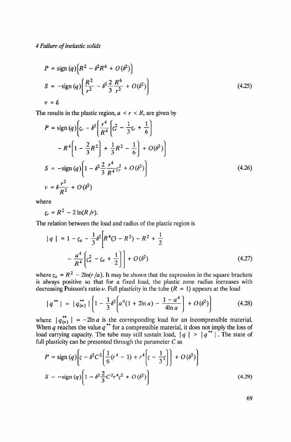
The results in the plastic region, a < r < R, are given by
P = sign (q+r -02(~: [~; - ~r + !) -R4 [l- ;R2) + ~R2 - !) + 0(02»)
(4.26)
where
~r = R2 - 2ln(R/r).
The relation between the load and radius of the plastic region is
1 2 [4( 2) 2 1 I q I = 1 - ~a - 38 R 3 - R - R + 2"
a4 [ 2 1)] 2 - R4 ~a - ~a + 2" + 0(8 ) (4.27)
where ~a = R 2 - 2ln(r /a). It may be shown that the expression in the square brackets is always positive so that for a fixed load, the plastic zone radius increases with decreasing Poisson's ratio v. Full plasticity in the tube (R = 1) appears at the load
Iq··1 = Iq;:) 1[1- ~02[a4(1 + 21na) - \~:4] + 0(62)] (4.28)
where I q(:) I = -2lna is the corresponding load for an incompressible material. When q reaches the value q'. for a compressible material, it does not imply the loss of load carrying capacity. The tube may still sustain load, I q I > I q.. I . The state of full plasticity can be presented through the parameter C as
P=Sign(q+-62C2[!(r4-1)+r4[~- ~~]) +0(62»)
(4.29)
69
4.2 Load bearing capacity of an ideal elastic-plastic solid ...
v = 6Cr2 + 0(62 )
I q I = I q(:) 1[1 - t02C2[a4a(1 + 2lna) _ \~:4] + 0(02)]
where!: = 1 + 2in r. The parameter C is equal to 1 for q = q" and approaches 0 with increasing load. For C = 0, the tube for a compressible material loses the capability to carry a load. The limiting load coincides with the limit q~' for a tube made from an incompressible material. The radial displacement Ur in the entire cross section of the tube becomes infinity in the limiting state. This can be seen from Equations (4.11), (4.29) and Ur = TCg,.
The results of this section show that compressibility can influence displacement while the limiting loads corresponding to loss of load carrying capacity are the same as for an incompressible material. Moreover, the limiting load does not always depend on the elastic properties of the material.
4.3 Stationary tensile crack in elastic-plastic material
Details of the stress-strain near the tip of a stationary crack is important for formulating crack initiation criterion. Reference can be found in [5, 6]. The work in this section will neglect geometric nonlinearity while the effects of finite deformation and changes in geometry near the crack tip have been treated [7, 8].
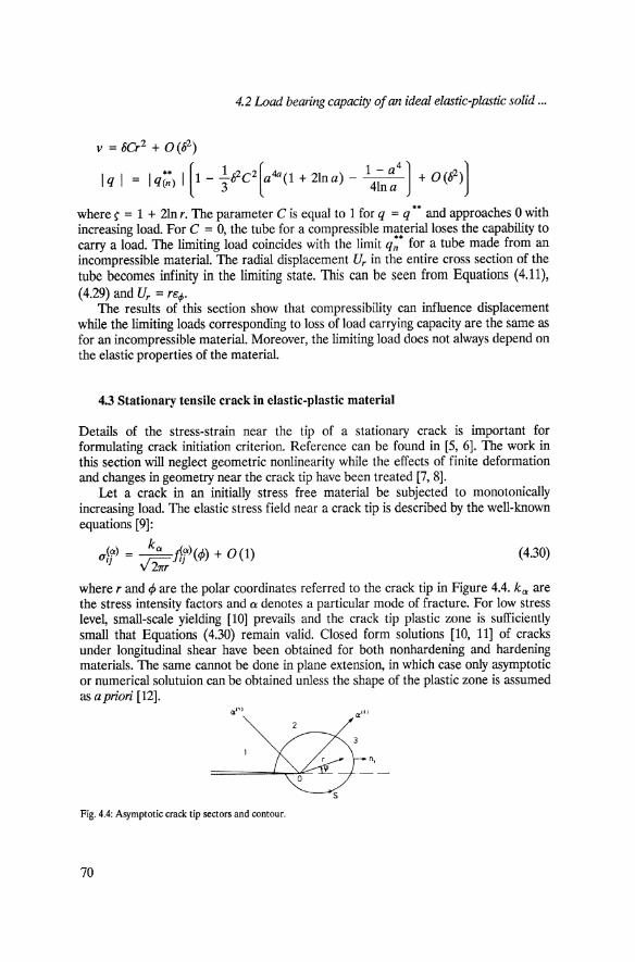
Let a crack in an initially stress free material be subjected to monotonically increasing load. The elastic stress field near a crack tip is described by the well-known equations [9]:
ufj) = )i;;f.j)(<!» + 0(1) (4.30)
where rand <!> are the polar coordinates referred to the crack tip in Figure 4.4. ka are the stress intensity factors and 0: denotes a particular mode of fracture. For low stress level, small-scale yielding [10] prevails and the crack tip plastic zone is sufficiently small that Equations (4.30) remain valid. Closed form solutions [10, 11] of cracks under longitudinal shear have been obtained for both nonhardening and hardening materials. The same cannot be done in plane extension, in which case only asymptotic or numerical solutuion can be obtained unless the shape of the plastic zone is assumed as a priori [12].
n,
s
Fig. 4.4: Asymptotic crack tip sectors and contour.
70

4 Failure o/inelastic solids
Asymptotic plane strain stress analysis
An asymptotic crack tip stress state as a function of the distances p assumes that
p« L, p« Rp (4.31)
where Rp is the maximum size of the plastic zone and L a characteristic length dimension. Solutions of this type have been found [13 - 15] for a linear power hardening material such that Uijeij - r -1 holds near the crack tip and the angular dependence of the stresses and strains depend on the rate of hardening.
Consider the asymptotic crack tip stress state in an ideal elastic-plastic material which is in a state of plane strain [16]. For anyone of the yield conditions in Equation (4.2), the stresses Un u; and ur ; are bounded when r -+ o. If, for all <A there exist a finite limit for the radial displacement
limu2(r, 4» = Ur(4)) r....o
then for all rP, there exist the corresponding limit U; (rP) for the angular displacement U;and
lim rer = lim re; = 0 r....o r....o
. 1 [dUr ] ~re,-; ="2 arP - U; . (4.32)
Shear strain e,-; is singular, of the order r -1, for all 4> that satisfy the inequality dUr /d4> - U; f O. 1bis is the highest possible order of strain singularity.
For monotonic loading and the deformation theory of plasticity, the path independentJ-integral [10] may be used, Figure 4.4:
[eii 1 au·
f = f f Uij deij dX2 - Uijnj-a I d? !I' 0 Xl
(4.33)
From Equations (4.1), (4.32) and (4.33), it follows that
(4.34)
In general, thef-integral is nonzero. The continuity of er; along rP = const. guarantees that at least one angular sector must exist where strain er; has a singularity of the order r- 1.
Owing to the symmetry of the problem, only the upper half plane x 2 > 0 needs to be considered. Near the crack tip, asymptotic expressions for strain with different orders prevail in the sectors rP = a (i). i = 1, ... , n in Figure 4.4. The boundary conditions for a continuous stress field have the form
rP = 11": u; = ur ; = 0
71

4.3 Stationary tensile crack in elastic-plastic material
Fig. 4.5: Small-scale yielding: (a) plastic elements and Cb) smooth elastic-plastic boundary.
4> = a(i): [0";] = [O"r] = [O"r;] = [v] = 0
oO"r 4> = 0: O"r; = 04> = o.
Introduce the stress function ~(r, 4» so that Equations (4.12) are satisfied:
1 o~ 1 o~ 0"2 = ---+--
r2 oq} 2 or
(4.35)
;j~ (4.36) 0"; = or2
1;j~ 1 o~ O"r; = -"2 oro4> + 72iii·
In the sector where cr; is singular with the order r -1 as seen from Equations (4.11) and (4.32), £I -+ 0 and S -+ 0 when r -+ o. The zero approximation of the stresses in this sector corresponds to a fan with slip lines radiation from a common point; the sector cannot close the crack flank nor coincide with the line ahead. If the plastic zone completely encloses the crack tip, a zero approximation in r and 0 can be determined from Equations (4.2) and (4.35); it consists of three sectors:
a(l) = 31r a(2) = ~ 4' 4
(JCl) = r; (1 _ cos 24», ~(2) = r; (1 - 24> + 3;) ,2
(J(3) = -(1 + cos 24> + '/1") 2
(4.37)
where the superscripts identify the sector number in Figure 4.4. The stress field corresponding to Equation (4.37) is the PrandtI solution which was used to describe the crack tip behavior [10, 17]. It is questionable whether the plastic zone should join the crack flank. If the plastic zone does not completely embrace the crack tip, then the stress field may be constructed from the zero approximation term of r and 0 in which the first sector enclosed by aCl) would be in the elastic state but not determined [18]. To find the angle a(1), it is necessary to invoke the continuity of v. According to the work in [18], the material in the first sector in Figure 4.4 is elastic, while the plastic fan prevails in the second sector. For a compressible material, this requires v = 0 = const 'lOin the first sector and v -+ 0 as r -+ 0 in the second sector. This condition, however, cannot be satisfied along 4> = aCl); the plastic zone for a compressible materia~ therefore, completely embraces the crack tip and the Prandtl
72

4 Failure of inelastic solids
field in Equation (4.37) corresponds to the zero approximation in r and 8 for the asymptotic stress field.
Small scale yielding near crack tip
Static problems of cracks have been solved by using the finite element method (FEM) [19]. Solutions, however, were seldom given in terms of the displacements as a rule and a priori assumption is usually made on the nature of the near field strain behavior such that the singularity is embedded into the elements. The elastic-plastic crack problems are solved by making use of the Prandtl- Reuss theory while the load is increased incrementally [20, 21].
Deformation theory has been used to obtain the plastic zone near the crack tip for an ideally elastic-plastic material [22, 23]; the results differed significantly from the corresponding results based on the incremental theory [24]. One of the possible reasons may be attnbuted to the use of displacement boundary condition instead of the stress condition in Equation (4.30) that are remotely away from the crack. Localized plasticity tends to affect the long distance displacements more than the stresses. It is therefore of interest to solve the small-scale yielding crack problem using the deformation theory with stress boundary conditions given by Equation (4.30). The method of local variations (MLV) [25] will be used. It involves the direct minimization of the finite difference representation of a functional by varying the unknown functions in steps. Since the stresses in an ideal elastic-plastic material are bounded, stress formulation would be the logical choice even for a compressible material.
Apply the variational principle of minimum complementary energy [26]. In plane strain for an elastic-plastic material (4.1), the Mises yield criterion and the stress boundary conditions, it can be shown that in the real state
I = 2~ l. ( ; (1 - 21/)(1 + v)p2 + ?-) dD +
+ J l.K (3p - sign (p w'3(1'~ - S2) dD -+ min D 6 p
(4.38)
where De is the elastic and Dp the plastic portion of the total region D. The minimum of I is to be found for the statically admissible stress fields that satisfy the boundary conditions. The region D is a semicircle with radius R where the origin coincides with the crack tip. The crack flanks are assumed to be traction free while for r :::: R, the stresses Ur and u~ correspond to Equations (4.30). The condition RIRp » 1 where Rp is the maximum radius of the plastic zone is enforced. The stresses in Equations (4.38) were expressed in accordance with Equation (4.36) for the finite difference approximation of the derivatives of the function~.
Fi~e 4.5 gives the results in the region D which contains 100 elements and kU(1'sR) :::: 2.52. Figure 4.5(a) shows the plastic elements and Figure 4.5(b) the elastic-plastic boundary after smoothing by interpolation. The elastic-plastic boundary is similar to that in [24]. The maximum radius of Rp = 0.064 kIl1'; of the plastic zone is situated between <P :::: 600 and 80° as compared with Rp = 0.053 kIl1'; given in [24].
73

4.3 Stationary tensile crack in elastic-plastic material
Figure 4.6 shows the stress dependence on c/J for r = 0.04 R. The stress field presented agrees qualitatively with the Prandtl field while qr~ agrees quantitatively. This study shows that the deformation and increment theories lead to similar results. The variational principle of complementary energy obtained the near crack tip solution without a priori knowledge of the asymptotic stresses. The algorithm of the MLV involving restrictions on the second derivatives is much more complex [27].
a..fr:. 2
a.,Ir:.
Fig. 4.6: Near field stress dependence on angle ~ in ideal elastic-plastic material.
Developed plasticity at crack tip
For small-scale yielding, crack initiation can be determined by the critical stress intensity factor k 1c • This approach does not apply when plasticity is developed. The path independent I-integral for plane crack problems in linear and nonlinear elasticity may be taken as a parameter to describe the crack tip state of affairs. The criterion I = J 1c was suggested for a wide class of materials [28, 29] including the elastic-plastic class. The strain energy density criterion is an example of another approach to the prediction of crack growth under the gross yielding [30]. It was shown in [28] that the I-integral did not depend so much on the local state of the material in the vicinity of the crack tip, i.e., on the hardening behavior
T = Tb), 'Y =yif«Cl -c2f + (c2 - c3f + (c3 - cd) (4.39)
for 'Y ~ 00. Moreover, this behavior cannot be verified experimentally. On the other hand, experimental stress-strain curve (4.39) for small "I should be taken into account with high accuracy when the I-integral is calculated. In [31], I-integral was computed for a compact tension specimen in Figure 4.7 using the deformation theory.
The principle of minimum energy was used [26] to obtain
1= l [~ + I rb) d"l) d~ -A ~min where A is the external work. Minimization was carried out using a modified version of the MLV [31] which decreases the calculation time. The calculations were performed for an alUlllinum alloy .n 20-1 (v = 0.3) with the uniaxial tension diagram shown in Figure 4.8. Plastic zone growth up to the fully developed condition were
74

4 Failure a/inelastic solids
p
-- b --H
I J H
p
Fig. 4.7: Compact tension specimen.
studied for different geometries. The results confirmed the use of deformation theory. Figure 4.9 shows the curve JO = 2J J.t(l + 1/)/3r;1 versus load P = P /V3Tsb for the specimen with H /b = 0.6, I/b = 0.25 and l/b = 0.5. The number of finite elements used is equal to 256. The dotted lines represent the corresponding results for the elastic material. Note that full plasticity did not develop for both of the load range shown in Figure 4.9.
60
20
005 010 015 <,
Fig. 4.8: Uniaxial response for aluminum alloy J1 20·1.
J.
008 016
Fig. 4.9: JO = 2Jpl,1 + V)/(3T#) versus load p = P /(..f3T,b) for the aluminum alloy .u 20-1 specimen with H/b = 0.6.
4.4 Dynamics of longitudinal shear crack in elastic-plastic medium
Quasistatic and dynamic crack propagation in elastic-plastic materials have been studied in many papers [32 - 39]. Use was made of the incremental and deformation
75

4.4 Dynamics of longitudinal shear crack in elastic-plastic medium
theories of plasticity and the asymptotic stress and strain field. As a result of unloading, there is no input energy into the crack tip for ideally plastic materials [32, 34, 38] and isotropically hardening materials [33, 35, 38]. Some new approaches to the solution of dynamic crack propagation in antiplanar strain for a linearly hardening material will be considered. Discontinuous stress fields are obtained. Necessary conditions for applying the energy approach to fracture are also discussed.
Basic equations
Consider the dynamic crack propagating under longitudinal shear in plane Xl andx2:
aw Ui = 0, U3 = W(xh X2, t), Ii = -a
Xi
Ojj = 033 = 0, 03i = Tj (4.40)
aTi cfw a "'/1 a 12 -=p-- --=--aXj at2 ' aX2 aX1
where p is the material density, t the time and U a the displacement vector. The hardening law is assumed to be isotropic and bilinear with elastic and plastic
rigidity J.I. and Jlp respectively. In what follows only singular stresses and strains are considered. The constitutive equations for loading, unloading and secondary loading may be written as
Ti = Jlp",/j, dT~O
ri = J.L(li -17rj), r5:T
o r - ro 0 ri = Ilpli + /DI(rj - rj) + Jlp --hi - rj), r ~ T, dr ~ 0
"'/
(4.41a)
(4.41b)
(4.41c)
where Tj and rj are, respectively, the stresses and strains at the beginning of plastic unloading; the superscript 0 denotes the corresponding quantities 1'/ and r? for secondary loading Note that .. = 1 - (u../II. .,2 = r·r· ~2 = ,...,... T2 = T..T.. r2 = r·r· 2 0 o· ., r-y ,-, 1 " I II '" 1 " 1 1
andro = rj rj. Consider a stress free crack propagating along the axis X 1 with a constant velocity
c. Introduce the moving coordinates x, y and the polar system r, 4> in Figure 4.10 such that
a a - = -c-. at ax
(4.42)
The energy g absorbed by the moving crack tip per unit of the crack front may be written as [40]
./([1 1 2aU a aUa ] aua ] g = lim oa{tdca{t + -pc ---- nl - ° ·--n· ds e--.o 2 ax ax al ax 1 s.
(4.43)
where s. is an arbitrary contour with a small diameter c moving with the crack tip and nj the normal to s e in Figure 4.10. Equation (4.43) is valid for an arbitrary constitutive
76

4 Failure of inelastic solids
(' }---x,
x,
Fig. 4.10: Shock lines L and small contour s. near moving crack tip.
law. For anti-plane strain, (4.40) takes the form
g = ~!. ([ J Tid')'i + ~ c 2')'; ]nx - (Txnx + Tynyh ] ds. (4.44)
The quantities with subscripts x andy refer to the moving coordinate system. Equation (4.44) is still valid for discontinuous stress fields with finite energy absorption along the shock lines.
Momentum conservation and displacement continuity are satisfied along the shock lines. Equation (4.42) and the condition of small r give
[Txnx + Tyfly - fJCixnx] = 0 (4.45)
[ixfly - ')'ynx] = O. (4.46)
Asymptotic stress field
Consider the continuous singular stress field near the crack tip moving with a subsonic velocity
c<b<a
where a = (1-'/ P )1/2 and b = (J1p / P )1/2 are the velocities of the elastic and plastic shear waves, respectively. The velocities c and b will be measured in units of a. Stress conditions and symmetry of the problem suggest that
Ty = 0, 'IjJ = if>
w=O,'IjJ=O
"I (4.47)
(4.48)
With the help of Equations (4.40) to (4.42), the equation of motion may be written as
B2 ifZw + ifZw = 0 ~ < 0 (4.49) ax2 ay2 'ax -
where
B =jI1- ~~ I.
For unloading from the plastic state, the equations of motion are of the form
77

4.4 Dynamics of longitudinal shear crack in elastic-plastic medium
(4.50)
Here, rx , ry , r~ and r~ are independent of x while A =~. The solution of Equations (4.49) and (4.50) is assumed to posses a power type
singularity. In general, the state of material in the different sectors near the crack tip may be different. Analysis of solutions of Equations (4.49) and (4.50) shows that, for a continuous field, the order of singularities cannot increase from one sector to another having the greater angle.
Consider the solution for which energy g is finite and nonzero. This condition can be satisfied provided that there exists at least One sector in which "y is of order r -1/2. Since the singularity order cannot increase with increasing 4>, this means that 0::; 4> ::; 4>' as loading takes place; hence
• 2h 2 _ c2 _ vi (2h 2 _ c2)2 + &4 cos (3 > 2 >-1 - 4c
tan (3' = B tan 4>'. (4.51)
Equation (4.51) implies that the sector of plastic loading can not touch the crack flank and therefore the unloading sector must follow it. The condition of unloading (m)j(ax) I ,p=,p' +0 ~ 0 leads to
(4.52)
It can be proved that for the continuous asymptotic stress field consisting of the sectors of loading and unloading, the inequalities (4.51) and (4.52) do not permit to satisfy the boundary condition (4.47). Nonzero g does not exist. This conclusion remains unchanged for secondary plastic loading [34, 38].
Consider crack propagation with velocity c that lies between the elastic and plastic case:
l>c>b. (4.53)
In this case, the material in the sector 0 ::; 4> ::; rP*, ahead of the crack is elastic and the solution is nonsingular. Equations (4.40), (4.41a) and (4.42) yield a differential equation of the hyperbolic type:
B2 iflw _ iflw = 0 ~ < 0 ax2 ay2 'ax -
(4.54)
for plastic loading. A singular solution of Equation (4.54) may coexist with the nonsingular elastic solution only along a line of discontinuity. The only possibility to fulfill the condition of plastic loadin~ is to suggest degeneration of the plastic sector onto the line of discontinuity 4> = 4> beyond which the state of unloading appears. Since the plastic zone degenerates into a line, only the constitutive equations for unloading are used. Therefore, all results will be valid for any isotropic hardening and for incremental theory of plasticity.
Thus, in the sector 4> ::; 4> < 7r, unloading from the plastic state takes place and hence Equation (4.50) is valid. Along the shock line and on the crack, the conditions in
78

4 Failure a/inelastic solids
Equations (4.45) to (4.47) should be satisfied. The solution in the sector of unloading satisfying the aforementioned conditions is
"Ix = ~(sinai cos A (tan a =A tan 4>, A = A(71" - a» JL(Ay)
_ kA 2 sin(A* +a*) * _ * * _ _ * rx - A •• 1-.1. (tana -Atan4>,A -A(71" a» 1'/JL(Ay) (sm a )
kA (. )A.nA cos(A* + a·) ] "i = sma S1 + • Y 1'/JL(Ay)A (sin a )1-.1.
r = _ kA cos(A* + a*) Y 7]v(Ayi (sina·)h\ .
(4.55)
It may be shown that condition of unloading (r ~ T for y = canst.) in the sector 4>. ~ 4> < r can always be satisfied if 0 < 4>; ~ 4>. ~ 4>. < 71", 0 < A1 ~ A ~ A2 < 1/2, where the values of the parameters 4>;, >v can be found for any c, b and 7] satisfying the conditions 1 > C > b, 1 > 1'/ > O. For >. = 1/2, the total energy absorption along the shock line is infinite, so this case is excluded from consideration. For A < 1/2, the above energy absorption is finite, but the energy input to the crack tip is zero (g = 0). The detailed investigation of the solution (4.55) and the conditions of its uniqueness may be found in [41, 42].
The case of discontinuous asymptotic stress fields for the stationary moving crack is analogous to that of a continuous one. The energy of deformation released from the elastic part of a body dissipates completely on the shock line in the former case and in the plastic zone in the latter case.
Energy approach to crack propagation in elastic-plastic material
Elastic-plastic problems of crack in stationary motion based on the classical theories of plasticity show that there is no energy input to the crack tip; this means that cracks cannot grow in an elastic-plastic material which is physically unsound. Other models such as that in [35, 38, 43, 44] may have to be considered.
For example, it was proposed in [35] to use the translational hardening model instead of the isotropic one. For very large deformation, the material behaved elastically and energy input prevailed at the crack tip. It may be shown that the more general law of unloading for which plastic or permanent deformation are bounded leads to the same conclusion. It is nevertheless interesting to consider other possibilities for which the classical models give energy input into the crack tip. As mentioned earlier, the stationary crack moving with lines of discontinuity gave no energy input. The other possibility is to investigate the accelerating motion of a crack. There is hope that this latter approach would yield energy input to the crack tip.
4.5 Fracture of viscoelastic solids
Fracture in solids is a time dependent process. Fast crack propagation does not take 79
4.5 Fracture of viscoelastic solids
place right away; it starts only after a certain period of load application. Before that, a slow process of latent fracture occurs even under constant external load. Such a behavior can be accounted for by considering the viscous properties of the material such as linear viscoelasticity.
Crack behavior in viscoelastic solids has been studied in the early papers [40, 45, 46]. Application of the Griffith criterion of fracture to the model without cohesive forces at the crack tip showed that the slow crack growth under constant external load (Le. crack kinetics) is absent. A crack can either be at rest or propagate dynamically. Many recent papers [47 - 49] have appeared and revealed that crack behavior in viscoelastic solids is still not understood.
Basic equations
The constitutive equations for viscoelastic solids stated in terms of the isotropic 0""." Coa and deviatoric (saf3' eaf3) parts of the stress O"aP and strain CaP tensors can be written as
1 0"00. = 3 K {coo.}, saf3 = 2J.t{eaf3}
where
1 1 saP = 0"af3 - 3"caf3O"Tt' eaf3 = caf3 - 3"Caf3cTt'
1 -{ ... } and J.t{ ••• } K
stand for the linear integral operators
J.t{f (r)} = J.4Jf (t) - J M (t - r)f (r) dr. o
(4.56)
(4.57)
The subscript ° denotes the instantaneous moduli and compliances while the subscript 00 denotes the long-term moduli and compliances. For instance
00
J.too = J.4J - J M(r) dr. o
The Griffith problem
Consider the Griffith problem of an unbounded plane that contains a cut of length 210 along the axis Xl with the crack centered at the origin. Assume that for t < 0, there are no stresses nor strains in the solids and at t = + 0, the stress 0'']2 = q is instantaneously applied at infinity and then maintained constant. It is evident that under this conditiqn, the crack length will increase so that, at time t, the crack length will be 21(t) and let) = c ~ 0. The correspondence principle [46, 50] can be applied.
80

4 Failure of inelastic solids
The asymptotic local stress U22 and displacement u 2 at the right tip of the crack are given by
u22 = qll/2Re(2(z _1))-1/2
u2 = qO{11/2Im(2(z - 1»1/2}. (4.58)
Here, z = Xl + ix2 and O{ ... } is the linear integral operator in the plane theory of elasticity, Equation (4.57). This operator is expressed in terms of p, and v for plane strain and plane stress states, respectively, as 0 = p,-1(1 - v) and 0 = p,-1(1 + v)-l. Using Equations (4.58) and (4.43), the energy density absorbed at the crack tip becomes
= 1I"q 2lOo [1 + -.l It O(t - r) ill I1/2 (r) q,(t r) drj g 2 11" 0 00 C (t) 11/2(t) ,
where
q,(t, r) = lim I Re(z -1(t»-1/2Im(z -1(r»-1/2 ds. e.....o s.
(4.59)
Assume that 'Y. is the surface energy associated with crack running at a velocity c; it is characteristic of a given material and can depend on the velocity c, i.e.,
g = 2'Y.. (4.60)
It can be easily shown that the function q,(t, r) is nonzero and equal to 11" only when I (t) = I (r). Thus, q, is equal to 11" for the crack at rest and equal to zero for the moving crack. As a result, the energy density g increases with time for a stationary crack and would preserve its initial value for a moving crack. A knowledge of q, is needed to obtain crack behavior for different loads.
Assume that the load satisfies the following inequality
( 4ry ) 1/2
q > 1I"10~ = qo· (4.61)
Equations (4.59) and (4.60) show that static equilibrium is not possible for t > 0 and that the crack propagates dynamically and can never come to rest since the crack becomes increasingly more unstable as it grows.
If q < qo, the crack is initially at rest. But in this case, 1 = 10 and Equation (4.59) shows that g increases although the stress intensity factor remains constant. It can occur that
( 4ry. ) 1/2
q < 11"/000 = qoo· (4.62)
Then the crack will be at rest at all times. If
(4.63)
81
4.5 Fracture a/viscoelastic solids
then there exist a time t = tr at which Equation (4.60) becomes valid and the crack starts to move dynamically never coming to rest. The time of fracture delay tr can be obtained from Equations (4.59) and (4.60):
Ir
Oo[:~ -1) = {O(r) dr. (4.64)
If the stress at infinity grows monotonically with time, then the time to fracture can be obtained from
2 Ir
qo 1 J -( -) = q (tr) + - O(tr - r)q (r) dr. q tr 00 0
(4.65)
A stable crack
Consider the effects of viscosity on the behavior of a crack, which is stable in an elastic solid. The example is the same as before except the load consists of a pair of equal and opposite concentrated forces P applied at the center of the crack. The asymptotic solution takes the form
(722 = PZ-1/2Re(2(z _1))-1/2
U2 = PO{Z-1/2Im(2(z _Z»1/2}.
With the help of Equations (4.66) and (4.59), the energy density becomes
= 1rp 2oo [1 + Jc f O(t - r) c (r) Z(t) I]i(t, r) drj. g 2l 1r 0 00 c(t) Z(r)
Assume first that the load is not too great so that
[ 4-y.Zo ] 1/2 _
P < 1l"11oo - P 00'
(4.66)
(4.67)
(4.68)
Although the right-hand side of Equation (4.67) increases with time, it never reaches the critical value 2/. and the crack will be at rest at all times. If the load is large enough so that
[ 4-y,/o ) 1/2
P > n1lo = Po·
Theng immediately exceeds 2/, so that
n1lop2 1(+0) =~.
(4.69)
(4.70)
The crack then begins to move slowly so that at time t = + 0 or at some later moment, it has nonzero velocity. According to Equation (4.67), this leads to the contradiction
82

4 Failure o/inelastic solids
that 1 = const. This presents a peculiar situation where the crack can neither be at rest nor can it move. A possible explanation is that the crack jumps in steps. Initially, it is overdriven and jumps to some other length, probably overshooting its equilibrium state and then comes to rest until it is again overdriven and so on. The amount of overload cannot be found from the analysis [51]. Hence, the crack propagates in a discontinuous step which can be made small to satisfy the equation of motion:
[ t 1 7rp2
I (t) = 4-y. no + ! O(r) dr . (4.71)
This relation is obtained from Equation (4.67) under assumption of no motion. For the range of load
Poo<P<Po the crack behavior is similar to that just described, except initially.
In viscoelastic solids, quasistatic crack growth is absent, i.e., a crack can either be at rest or already in fast motion [46, 52]. However, for loads in the range described by Equation (4.63), the crack can be at rest only for some incubation time tr; hence, in a degenerate fashion, the quasistatic crack growth can exist in a model of fracture of a linear viscoelastic solid without cohesive forces.
4.6. Constitutive instability
According to Figure 4.1, failure behavior of material with microcracks may be described in terms of elastic-plastic constitutive relation [53] where the development of macroscopic defects is identified with the peculiar localized material instability. The approach appears to apply for materials that are initially weak whereby the classical concept of a dominant crack fails to apply. In contrast to [53], an integral instability criterion is proposed with the additional consideration of discreteness so that localization can be proved rather than postulated and its favorable mode can be obtained.
Integral criterion
Consider a system including the body and the self-balanced forces. Let the system be transformed from an eqUilibrium state to some other neighboring state under the action of applied forces. If there exists a neighboring state, during transition to which the energy is drawn from the system by the applied forces, then the equilibrium state is said to be slightly unstable [54].
Let the elastic-plastic constitutive law be used in the incremental form:
\7 _ L _ {LP For plastic response ua{3 - Lcr{Yy>.f:'1>" - LeFor unloading (4.72)
where ~a{3 is the Yaumann increment of the Cauchy stress tensor, eafj the small virtual 83

4.6 Constitutive instability
strain tensor, L':,p,.,).. the constant stiffness tensor, and L~ the function depending on the load parameter but not of time nor ec43. The instability criterion means that there exists at least one small virtual strain field for which the piecewise-quadratic functional
(4.73)
is nonpositive. Here, (1~ is a fictitious Cauchy stress tensor related to the boundary tractions. If the constraint is produced by the boundary forces, then their action is assumed to suppress instability:
J ~~ec43 dD ~ o. (4.74) D
The system can become unstable only due to the instability of the material itself, i.e., due to nonpositiveness of the constitutive part of the integrand Larry).. ec43 e1)... It can take place only for the plastic response because the quadratic form L':,p,.,).. ec43 e-y>. is definitely positive for unloading.
In addition to the instability criterion, it is necessary to introduce a selection principle for identifying the mode that is more likely to cause instability. Let the load process be determined by a monotonically increasing parameter. The instability mode is assumed to be primary if it corresponds to the least value of this parameter. The constitutive law is [53]
p _ ~ _ 3pKS c43 + /3bc43 [ ~) L"af3rr>.e-y>. - 2pec43 + 3K bc43 3K(p, + h) + m/3 pi. + m 3K
L~e-y>. = 2pec43 + 3~bc43 (4.75)
where e c43 is the deviatoric strain tensor, S c43 the normalized deviatoric stress tensor (S c43S c43 = 2), h is the plastic hardening modulus, m is the internal friction coefficient and /3 is the dilatancy factor. In Equation (4.75), e = eoa and € = e c43S c43. The condition of plastic response is
f! = 3pK€ + me > 0 (4.76) 3K(p,+h)+m/3-
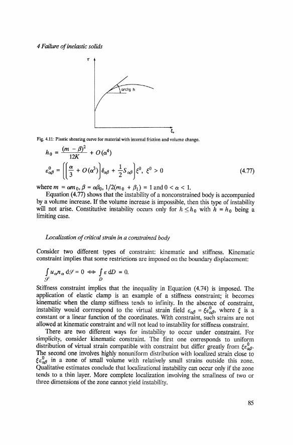
Figure 4.11 shows the plastic shearing curve which is assumed to be convex, i.e., the plastic modulus decreases monotonically with deformation. The body undergoes uniform plastic loading up to' the onset of instability, when a nonuniform strain distribution arises. Hence, for the state under consideration, the plastic modulus h distribution is uniform. The value of (-/z) is adopted [55] as a parameter involved in the selection principle.
Note that the constitutive law is nonlinear due to discontinuity in the modulus. This nonlinearity together with constraint cause localization. A simple case of constitutive instability corresponds to a nonconstrained body. In this case, Equation (4.73) reduces to degeneration of the quadratic form L~).. (h )ec43e1)... The critical values are
84
4 Failure of inelastic solids
'. Fig. 4.11: Plastic shearing CUlve for material with internal friction and volume change.
h = (m - (3)2 + O«(i) o 12K
o:~ = [[; + O(a3 )]oa,8 + ts",,]eo, eO> 0 (4.77)
wherem = £¥mO, (3 = et/3o, 1/2(mo + (31) = 1 and 0 < a < l. Equation (4.77) shows that the instability of a nonconstrained body is accompanied
by a volume increase. If the volume increase is impossible, then this type of instability will not arise. Constitutive instability occurs only for h ~ h 0 with h = h 0 being a limiting case.
Localization of critical strain in a constrained body
Consider two different types of constraint: kinematic and stiffness. Kinematic constraint implies that some restrictions are imposed on the boundary displacement:
J u"n" dg' = 0 ~ J c dD = O. g' D
Stiffness constraint implies that the inequality in Equation (4.74) is imposed. The application of elastic clamp is an example of a stiffness constraint; it becomes kinematic when the clamp stiffness tends to infinity. In the absence of constraint, instability would corrrespond to the virtual strain field 0:"" = eo:~", where e is a constant or a linear function of the coordinates. With constraint, such strains are not allowed at kinematic constraint and will not lead to instability for stiffness constraint.
There are two different ways for instability to occur under constraint. For simplicity, consider kinematic constraint. The first one corresponds to uniform distribution of virtual strain compatible with constraint but differ greatly from ec~. The second one involves highly nonuniform distribution with localized strain close to ec~ in a zone of small volume with relatively small strains outside this zone. Qualitative estimates conclude that localizational instability can occur only if the zone tends to a thin layer. More complete localization involving the smallness of two or three dimensions of the zone cannot yield instability.
85

4.6 Constitutive instability
In the above mentioned estimates, continuity of the virtual strain components tangent to the zone of localization was not taken into account. Such consideration is adequate for one dimension where no tangent components occur and the exact solution of the problem for both types of constraint [52] gives a 6'-like virtual strain distribution, i.e., complete localization. The latter can also occur for arbitrarily small constraint stiffness in two dimensions, but not for three dimensions.
Localization in three dimensions can be illustrated by two model problems [55 -57]. In the first, the critical parameters are determined under the condition that instability is characterized by complete localization in extremely thin layers. The analysis of the functional G (h, caP) is then reduced to the analysis of the integrand L~). (h )caj3c,,/). under the condition that there exists a zero plane for the tensor caj3, because its components tangent to the localization layer surface must be zero. The critical values obtained are h. < ho and c:p = 1/2(naEP + npga). For the deviator of pure shear S aj3 = 61a6lf3 - 62c.6'2p we have:
na = cos(; -1/;]61a + sin ( f -1/;]62a
ga = cos( -; + 1/;]61a + sin[ -f + 7f)02a
t/J ;; t arcsin( P./~+ 1 l (4.78)
The two likely planes of localization planes are orthogonal to na andgw respectively. While the character of deformation for complete localizaiton is revealed in the
first problem, the favorable condition for localizational instability is not determined. The second model will study the situation in search for localization as a function of constraint stiffness. The body is assumed to be a plane layer with unit thickness and elastic clamp stiffness c for varying layer thickness as shown in Figure 4.12. The boundary planes are parallel to one of the two favorable planes of localization. The zone of localization is assumed to be a plane layer of thickness a, where 0 S a S 1. The critical value a = a.(c) corresponds to a threshold constraint stiffness c. which is magnitude of the elastic modulus:
Oscsc. ~ a. = 1
c = c. ~ a. is arbitrary between 0 and 1
c > c. ~ a. = O.
(4.79)
Simultaneous variations of the orientation and thickness of the localized zone can also be examined. Localization occurs in the form of a 6'-like distribution of dyadic strain given in Equation (4.78). Localizational instability is not always the favorable mode of constitutive instability; it occurs only when the constraint is sufficiently stiff, Equation (4.79).
86

4 Failure o/inelastic solids
c ~ ~ ~ ~
( D. tn )
0,
( a 1 1 D.
Fig. 4.12: Loca1ization in constrained body.
Fault systems
Since all localizational instability modes correspond to the same critical value h., discreteness of the material must be considered to eliminate this degeneration It is postulated that localization layer thickness cannot be less than a certain dimension do that is inherent in the material. The instability modes are considered to be almost completely localizational. The selection principle for them takes the modified form based on perturbation procedure with small parameter 6 = dolL with L being a characteristic length dimension [55].
h =ho -6h 1 +0(6)
J L~). caPc..,). dD h1 = 3pK + (tl-IpK + 1) .::.De=--___ _
3K(J.t + h.) + m(3 (4.80)
Jedw
J L#cafJc..,>. dD -h1 = min ~ A= .:::D.:..e _____ = min
Here, wp is the union of middle-planes of the localization layers and € is the localized strain amplitude distribution. The functional A. governs the geometric similarity of the localization instability patterns; when it is invariant under translation, it governs also the equal spacing of localization layers. Equation (4.80) will be used to estimate a qualitative feature of the fault systems which corresponds to the shear of a square box and a strip sandwiched between rigid walls. In both cases, the finite-element method is used to determine the kinematics in the unloading region and the corresponding piecewise-linear distribution of € along the localization lines. Figure 4.13 shows the parallel localization lines equally spaced at aL; they are obtained in [55 - 57] in the case of a box. For the strip (Figure 4.14). localization lines of two possible directions (almost parallel and almost perpendicular to the strip axis) are not equivalent: the former are 2/0. times longer and, hence, are favorable, if the lines of a single type are considered But in general the combination of both types may appear to be absolutely
87

4.6 Constitutive instability
Fig. 4.13: Localization lines for a box.
favorable, and this possibility should also be investigated.
Fig. 4.14: Localization lines for a strip.
Under the conditions of a strip, sandwiched between rigid walls, the above mentioned possibility has not been realized. The 'echelon' fault system formed only by the long lines overlapping approximately by a half of their length (Figure 4.14) has proved to be favorable. These results agree qualitatively with the experiments in [55, 56].
References
[1] RABOTNOV, Yu.N., Mechanics of Defonnable Solids, Moscow, Nauka (in Russian) 1979. [2] SOKOLOVSKY, V.V., Theory of Plasticity, Moscow, Vischaya shkola (in Russian) 1969. [3] MUKHAMEDIEV, ShA. and NIKITIN, L.V., [zvestiya AN SSSR. Mechanika tverdogo tela, No.2
(in Russian), 1981, pp. 39-47. [4] IYLEV, D.L. and ERSHOV, L.V., Perturbation Method in the 77!eory of Elastic-Plastic Body,
Moscow, Nauka (in Russian) 1978. [5] VITVITSKY, P.M., PANASJUK, V.V. and IAREMA, SJ.A., Problemi prochnosti, No.2, 1973,
pp.3-18. [6] RICE, I.R., The Mechanics of Fracture, AMD, Vol. 19, 1977, pp. 23 - 53. [7] RICE, J.R. and JONSON, MA., The role of large crack tip geometry changes in plane strain
fracture, in Inelastic Behavior of Solids, Kanninen et ai., eds., McGraw-Hill, 1970, pp. 641- 672. [8] McMEEKING, R.M.,J. Mech. Phys. Solids, Vol. 25, No.5, 1977, pp. 357-381. [9] PARIS, P.c. and SIR, G.c., Analysis of stress state near crack (transl. in Russian). Prikladnie
voprosy vjaskosty razrnchenia, Moscow, Mir, 196ft [10] RICE, J.R., Mathematical Analysis in the Mechanics of Fracture, in Fracture: An Advanced
Treatise, H. Liebowitz Ed., Academic Press, Vol. 2, 1967, pp. 191- 311. [11] HULT, JA. and McCLINTOCK, FA., Elastic-plastic stress and strain distribution around sharp
88

4 Failure o/inelastic solids
notches under repeated shear, Int. Congr. for Appl. Mech., Brussels, Vol. 8, 1957, pp. 51- 58. [12] DUGDALE, D.S., l. Mech. Phys. Solids, Vol. 8, No.2, 1960, pp. 100-104. [13] CHEREPANOV, G.P., Prikladnaya matematika i mechanika, Vol. 31, No.3, 1967, pp. 476-488
(in Russian). [14] RICE, J.R. and ROSENGREN, J., I. Mech. Phys. Solids, Vol. 16, No.1, 1968, pp. 1-12. [15] HUTCHINSON, J.W., J. Mech. Phys. Solids, Vol. 16, No.1, 1968, pp. 13 - 3l. [16] MUKHAMEDIEV, ShA., Stresses and strains under plane strain of nonhardening elastic-plastic
material. Application to Fracture (in Russian), VINITI, No. 1188 -74, 1974, DEP. [17] CHEREPANOV, G.P., Mechanics of Brittle Fracture (in Russian), Moscow, Nauka, 1974. [18] IBRAGIMOV, VA. and TARASJUK, N.E.,IzvestiyaAN SSSR. Mechanika tverdogo tela, No.5,
1976, pp.184-185. [19] ZIENKIEWICZ, O.c. and CHEUNG, Y.K., The Finite Element Method in Structural and
Continuum Mechanics, McGraw-Hili, 1967. [20] YAMADA, Y., YOSHIMURA, N. and SAKURAI, T., Int. I. Mech. Sci., Vol. 10, No.5, 1963, pp.
121-135. [21] MARCAL, P.V. and KING, J.P., Int. I. Mech. Sci., Vol. 9, No.3, 1967. [22] KUDRAJAVTZEV, VA., PARTON, V.Z., PESKOV, JuA. and CHEREPANOV, G.P., lzvestiya
AN SSSR. Mechanika tverdogo tela, No.5, 1970, pp. 65 -74 (in Russian). [23] PARTON, V.Z. and MOROZOV, E.M., Mechanics of Elastic-Plastic Fracture (in Russian),
Moscow, Nauka, 1974. [24] LEVY, N., MARCAL, P.V., OCTERGREN, W.J. and RICE, J.R., Int. I. Fract. Mech., Vol. 7, No.
2, 1971, pp.143-156. [25] CHERNOUSKO, F.L. and BANICHUK, N.V., Variational Problems in Mechanics (in Russian),
Moscow, Nauka, 1973. [26] KACHANOV, L.M., Foundations of Theory of Plasticity (in Russian), Moscow, Nauka, 1973. [27] MUKHAMEDIEV, ShA. and NIKITIN, LV., Prikladnaya matematika i programmirovanie,
Kishinev, Shtiintsa, No. 12, 1975, pp. 92-108. [28] BROBERG, K.B., l. Mech. Phys. Solids, Vol. 19, No.6, 1971, pp. 407 -418. [29] LANDES, J.D. and BEGLEY, lA., I-integral as a failure criterion, 5th National Symposium on
Fracture Mechanics, University of Illinois, 1971. [30] SIH, G.C., and MADENCI, E., Eng. Fracture Mech., Vol. 18, No.3, 1983, pp. 667-677. [31] MUKHAMEDIEV, ShA., NIKITIN, L.V. and YUNGA, S.L., Isvestiya AN SSSR. Mechanika
tverdogo tela., No.1, 1976, pp. 76-83 (in Russian). [321 ACHENBACH, J.D. and DUNAEVSKY, V., J. Mech. Phys. Solids, Vol. 29, No.4, 1981, pp.
283-303.
[33J AMAZIGO, J.C. and HUTCHINSON, J.W., I. Mech. Phys. Solids, Vol. 25, No.2, 1977, pp. 81-93.
[34J CHITALEY, A.D. and McCLINTOCK, FA., I. Mech. Phys. Solids, Vol. 19, No.3, 1971, pp. 147-163.
[35] IBRAGIMOV, VA., Prikladnaya matematika i mechanika, Vol. 40, No.2, 1976, pp. 337-345 (in Russian).
[36] RICE, J.R., Elastic-plastic crack growth, MRL E-124, Brown University, 1980. [37] SLEPJAN, LJ., IzvestiyaAN SSSR Mechanika tverdogo tela, No.1, 1974, pp. 57 - 67 (in Russian). [38] SLEPJAN, L.I., Mechanics of Cracks, (in Russian), Leningrad, Sudostroenie, 1981. [39] YU-CHEN, G. and KEH-CHIN, H., Elastic-plastic fields in steady crack growth in a strain
hardening materia~ Advances in Fracture Research, D. Francois Ed., Pergamon Press, Vol. 2,
89

References
1981, pp. 669-682. [40] KOSTROV, B.V., NIKITIN, L.V. and PUTMAN, L.M., Izvestiya AN SSSR. Mechanika tverdogo
tela, No.3, 1969, pp. 112-125 (in Russian). [41] MUKHAMEDIEV, ShA. and NIKITIN, L.V., Izvestiya AN SSSR. Mechanika tverdogo tela, No.6
(in Russian), 1988. [42] KONDAUROV, V.I., MUKHAMEDIEV, ShA., NIKITIN, L.V. and RYZHAK, E.I., Rock
Fracture Mechanics, Moscow, Nauka (in Russian), 1987. [43] SIH, G.C., TheoreticalApplied Fracture Mech., Vol. 4, No.3, 1985, pp.157-173. [44] SIH, G.C. and MACDONALD, B., Eng. Fracture Mech., Vol. 6, 1974, pp. 361-386.
[45] WILLIAMS, M.L., The fracture of visco-elastic material, Fracture of Solids, Interscience Publishers, N.Y., 1963, pp. 157 -188.
[46] KOSTROV, B.V., NlKITIN, L.V. and PUTMAN, L.M., Izvestiya AN SSSR, Fizika Zeml~ No.7, 1970, pp. 20-35 (in Russian).
[47] CHRISTENSEN, R.M., Int. J. Fracture, No.1, 1979, pp. 3-21. [48] McCARTNEY, L.N., Int. Journal of Fracture, No. 13, 1977, pp. 641-654. [49] POPELAR, C.H. and ATKINSON, S.,!. Mech. Phys. Solids, Vol. 28, No.2, 1980, pp. 79-93. [50] GRAHAM, GA., Quart. Appl. Math., No. 25, 1968, pp. 167 -185. [51] MOLCHANOV, AE. and NIKITIN, L.V., Izvestiya AN SSSR. Mechanika tverdogo tela, No.2,
1972, pp. 181-194. [52] KOSTROV, B.V. and NIKITIN, L.V., Archiwzlln Mechaniki Stosowaney, Vol. 6, No. 22,1970, pp.
749-775.
[53] RUDNICKI,J.W. and RICE,J.R.,!. Mech. Phys. Solids, Vol. 23, No.6, 1975, pp. 371-394. [54] DRUCKER, D.C., J. Appl. Mech., Vol. 26, No.1, 1959, pp. 101-106. [55] RYZHAK, Ye.I.,Izvestiya AN SSSR. Mechallika tverdogo tela, No.5, 1983, pp. 127 -136. [56] NIKITIN, L.V. and RYZHAK, Ye.I., Doklady AN SSSR, Vol. 230, No.5, 1976, pp. 1203-1206. [57] NIKITIN, L.V. and RYZHAK, Ye.I., Izvestiya AN SSSR, Fizika Zemli, No.5, 1977, pp. 22- 37. [58] REVUZHENKO, AP., STAZHEVSKY, S.B. and SHEMYAKIN, E.I., Fiziko-technicheskie
problemy, No.3, 1974, pp. 130 -133. [59] BYERLEE, J., MYACHKIN, V., SUMMERS, R. and VOEVODA, 0., Tectonophys., Vol. 44,
NO. 1-4, 1978, pp. 161-171.
90

![chapter – 21 solids [surface area and volume of 3-d solids]](https://static.fdokumen.com/doc/165x107/632737f8051fac18490e22eb/chapter-21-solids-surface-area-and-volume-of-3-d-solids.jpg)