The application of droplet digital PCR technology to measure ...
1 Copyright © 2010 by ASME
Proceedings of ICFD 10: Tenth International Congress of Fluid Dynamics
December 16-19, 2010, Stella Di Mare Sea Club Hotel, Ain Soukhna, Red Sea, Egypt
ICFD10-EG-3153 Computational and Experimental Study for Droplet Behavior
Under Flashing Condition
H. A. Moneeb Professor of Combustion
Department of Mechanical Power Engineering Helwan University
Hafez A. El-Salmawy Associate Professor
Department of Mechanical Power Engineering Zagazig University [email protected]
Ahmed H El-Kholy
Research Fellow Department of Mechanical
Power Engineering, Helwan University
Khaled M. Shebl Associate Professor
Department of Mechanical Power Engineering, Helwan
University
Abdel Rahman El-Lathy Assistant Professor
Department of Mechanical Power Engineering, Helwan
University
ABSTRACT The phenomenon of droplet evaporation under flashing condition has been investigated. Both computational and experimental techniques have been considered in this investigation. In the computational investigation, the physical processes, which include; internal bubble nucleation, bubble growth, droplet ballooning, bubble collapse and droplet disruption, are modeled. The model has been extended to cover the post droplet disruption phase. The experimental study has been carried out to verify the computational model using a suspended water droplet. A test rig has been designed and manufactured and equipped with all necessary measuring instruments, data acquisition and image processing facilities for this task. It has been found that, there are three regimes for the droplet behavior under flashing condition. These are related to the degree of superheat in comparison with its critical value. These regimes are: surface flash evaporation, surface flash evaporation combined with droplet ballooning and droplet disintegration combined with normal evaporation of the satellite droplets. By comparing the predicted results with experimental values, it has been found that the model predicts successfully the main features of the phenomenon with acceptable accuracy. Also, it has been found that, as a result of droplet disintegration the evaporation time is reduced tremendously. It could approach 1/100 of the original evaporation time with no degree of superheat. KEYWORDS: DROPLET, EVAPORATION, FLASHING AND ATOMIZATION INTRODUCTION
Atomization is the process of transforming a liquid bulk into small droplets. It aims at enhancing liquid vaporization
through increasing the surface to volume ratio. In the absence of external or internal disruptive forces, surface tension tends to pull the liquid into the form of a droplet, since this has a minimum surface energy. Liquid viscosity exerts a stabilizing effect by opposing any change in the system geometry. On the other hand, aerodynamic forces and cavitations as well as flashing processes may promote the bulk liquid disruption by applying external and internal forces. Breakup occurs when the magnitude of the disruptive force exceeds the consolidating surface tension force.
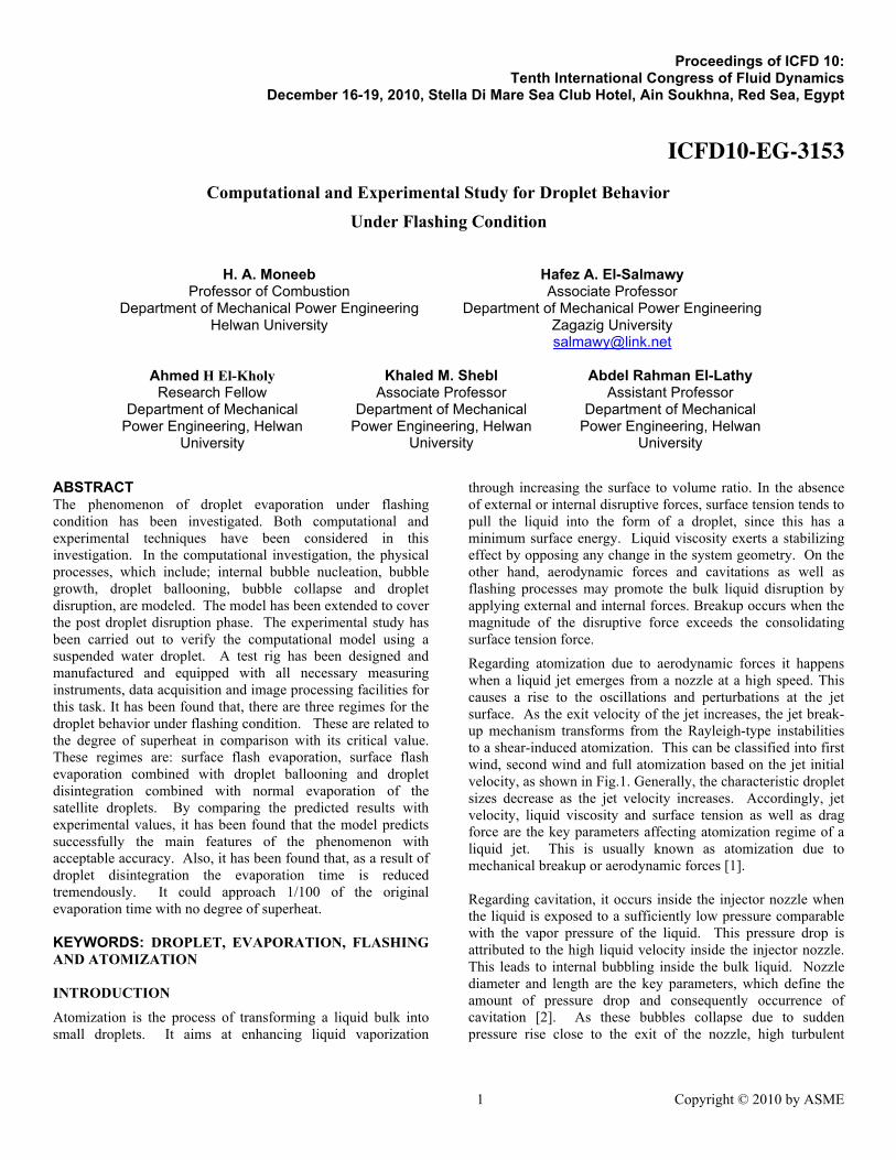
Regarding atomization due to aerodynamic forces it happens when a liquid jet emerges from a nozzle at a high speed. This causes a rise to the oscillations and perturbations at the jet surface. As the exit velocity of the jet increases, the jet break-up mechanism transforms from the Rayleigh-type instabilities to a shear-induced atomization. This can be classified into first wind, second wind and full atomization based on the jet initial velocity, as shown in Fig.1. Generally, the characteristic droplet sizes decrease as the jet velocity increases. Accordingly, jet velocity, liquid viscosity and surface tension as well as drag force are the key parameters affecting atomization regime of a liquid jet. This is usually known as atomization due to mechanical breakup or aerodynamic forces [1]. Regarding cavitation, it occurs inside the injector nozzle when the liquid is exposed to a sufficiently low pressure comparable with the vapor pressure of the liquid. This pressure drop is attributed to the high liquid velocity inside the injector nozzle. This leads to internal bubbling inside the bulk liquid. Nozzle diameter and length are the key parameters, which define the amount of pressure drop and consequently occurrence of cavitation [2]. As these bubbles collapse due to sudden pressure rise close to the exit of the nozzle, high turbulent
2 Copyright © 2010 ASME
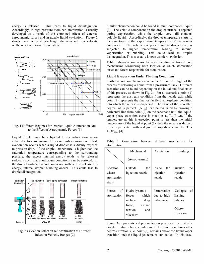
energy is released. This leads to liquid disintegration. Accordingly, in high-pressure atomizer, atomization is usually developed as a result of the combined effect of external aerodynamic forces and in-nozzle liquid cavitation. Figure 2 shows the effect of nozzle length, diameter and flow velocity on the onset of in-nozzle cavitation.
Fig. 1 Different Regimes for Droplet Liquid Atomization Due
to the Effect of Aerodynamic Forces [1] Liquid droplet may be subjected to secondary atomization either due to aerodynamic forces or flash atomization. Flash evaporation occurs when a liquid droplet is suddenly exposed to pressure drop. If the droplet temperature is higher than the saturation temperature corresponding to the surrounding pressure, the excess internal energy tends to be released suddenly such that equilibrium conditions can be restored. If the droplet surface evaporation is not sufficient to release this energy, internal droplet bubbling occurs. This could lead to droplet disintegration.
Fig. 2 Caviation Effect on Jet Atomization at Different Injection Velocity Ranges [2]
Similar phenomenon could be found in multi-component liquid [3]. The volatile component on the droplet surface is depleted during vaporization, while the droplet core still contains volatile liquid. Accordingly, the droplet temperature starts to increase towards the vaporization temperature of the heavier component. The volatile component in the droplet core is subjected to higher temperature, leading to internal vaporization or bubbling. This could lead to droplet disintegration. This is usually known as micro-explosion. Table 1 shows a comparison between the aforementioned three mechanisms considering both location at which atomization onset and forces responsible for atomization.
Liquid Evaporation Under Flashing Conditions Flash evaporation phenomenon can be explained in light of the process of releasing a liquid from a pressurized tank. Different scenarios can be found depending on the initial and final states of this process, as shown in Fig. 3. For all scenarios, point (1) represents the upstream condition from the nozzle exit, while point (2) represents the final or far field atmospheric condition into which the release is dispersed. The value of the so-called degree of superheat (ΔTsh) can be evaluated by drawing a horizontal line from point (2) on the schematic until the liquid-vapor phase transition curve is met (i.e. at Tsat(Patm)). If the temperature at this intersection point is less than the initial temperature of the liquid at point (1), then the release is defined to be superheated with a degree of superheat equal to T1 - Tsat(Patm) [4].
Table 1. Comparison between different mechanisms for atomization
Mechanical
(Aerodynamic)
Cavitation Flashing
Location where atomization starts
Outside the injection nozzle
Inside the injection nozzle
Outside the injection nozzle
Forces of atomization
Hydrodynamic forces which include drag force, surface tension and viscosity
Perturbation due to high turbulence
-Collapse of flashing bubbles
-Micro-explosion
Figure 3a represents a depressurization process at the exit of a nozzle to atmospheric conditions. If the fluid conditions after depressurization, (i.e. point (2), remains above the liquid/vapor transition line) the liquid jet remains sub-cooled. In this case,

3 Copyright © 2010 ASME
€
αs =
760(Td −Tb )0.26 , 0 ≤ (Td −Tb ) ≤ 5
27(Td −Tb )2.33 , 5 < (Td −Tb ) ≤ 25
13800(Td −Tb )0.39 25 < (Td −Tb )
⎧
⎨ ⎪
⎩ ⎪
atomization occurs as a single-phase homogeneous jet, which disintegrates through aerodynamic interaction and wave instabilities at the liquid surface. The so-called ‘flashing’ process occurs if point (1) exists above the liquid/vapor phase change line, and point (2) below the phase line, as shown in Fig. 3b. In this case, thermodynamic conditions within the nozzle reach a superheated condition, where the pressure is dropped below the local saturated vapor pressure. This condition is often combined with a vapor production within the jet, to release the extra energy, until the transitional superheat condition is exceeded. If the fluid is stored under saturated conditions as a two-phase mixture, then the situation represented by Fig.3c is realized. In this case, liquid droplets in the mixture are vaporized due to flashing. Finally, if point (1) is stored as a vapor in the pressure tank, and point (2) exists below the phase change line, as presented in Fig.3d, a homogenous single-phase vapor jet is released.
Fig. 3 Thermodynamic Boundary Conditions in Relation To
Saturated Conditions [4]
Several researchers have studied the flashing phenomenon using different research approaches. Saury et al [5] have studied the flash evaporation phenomenon of water in a container placed in a test chamber, which is subjected to sudden depressurization. Their experiment aims at analyzing the evolution of several characteristics parameters such as; flashing time and evaporated mass. The evaporated mass flow was calculated through tracking the temperature measurements of six thermocouples, which immersed in the bulk liquid inside the container at different height levels. They introduced the dimensionless number “Non Equilibrium Function “NEF” to characterizes the evolution of temperature during the flashing phenomenon.
(1)
The instantaneous evaporated mass flow rate is obtained, according to the following equation:
(2)
where A is the tank area and H the water height.
Zuo et al.[6] studied computationally and experimentally the behavior of fuel spray at different combustion chamber designs and injection strategies in Gasoline direct Injection Engine GDI. They considered the effect of preheating on gasoline before injection. They developed a model for the evaporation process, which considers the heat transfer from both the interior of the droplet and the surrounding gas, under superheat conditions. They found that, it causes significant changes in the fuel spray configuration and fuel-air mixing process. To quantify the overall heat transfer coefficient within the droplet, they suggested a correlation derived from spray evaporation measurements in internal combustion engines. This correlation takes the following forms depending on the range of the degree of superheat:
(3)
Schmehl et al. [7] studied the start-up of a hypergolic spacecraft engine, under vacuum condition. The aforementioned problem has been simulated through accelerated liquid droplets in a convergent – divergent nozzle. Due to the high flow velocity, both pressure and temperature experience steep drop. Accordingly, the two-phase mixture is subjected to significant non-equilibrium behavior. Three dimensional-computational fluid dynamics (3D-CFD) analysis of the oxidizer flow has been considered. This included modeling of the droplet behavior associated with the low-pressure conditions. The mathematical model is an extension of the classical D2-theory. However, the model considered the extra heat transfer associated with the flash evaporation of superheated droplets. They developed an implicit expression for the total evaporation rate of the droplet. Furthermore they developed an equation for the change in the droplet temperature with time. They found that, in the all cases, the droplets leaving the combustion chamber are still superheated. However, the temperature of the smaller droplets decreases faster towards the local boiling temperature. This occurs at a nearly constant level in the combustion chamber and decreases with the reduction of the static pressure in the accelerated nozzle flow. They concluded that, the small droplet is easy to lose its extra energy by surface evaporation. On the contrary, this is not the case of large droplets.

4 Copyright © 2010 ASME
The present work considers the setup, which has been used by Saury et al. [5], but for a single droplet suspended on a thermocouple junction, instead of a liquid bulk in a container. This will enable highly controlled experimental conditions. This can provide better physical understanding of the phenomenon. Starting from physical understanding, it will become possible to develop a mathematical model, which expresses droplet behavior during the different phases of the droplet lifetime, as well as evaporation regimes. The model shall be able to predict the possibility for droplet disintegration depending on the degree of superheat and other influencing parameters. Not only that but the model shall be also able to predict the disintegration process including number and sizes of satellite droplets and their kinetic energy as a function of the intensity of the disintegration. The model shall extend to provide information on post disintegration phase. It shall provide information on the behavior of the satellite droplet and their lifetime. The controlled experimental results will be used to verify the model. On the other hand, the model will be used to provide information, which cover wide spectrum of working conditions, which are not covered by the experimental work.
EXPERIMENTAL WORK The scope of the experimental work is to study the behavior of a suspended droplet evaporating under flashing condition. This is made possible through placing a droplet in a suddenly depressurized test chamber. An experimental setup has been designed and manufactured for the present work to facilitate measuring the phenomenon where separation of effective parameters can be assured [8]. As shown in Fig. (4), the experiment includes; breeding and inserting a single water droplet into the test chamber. This droplet is suspended on a thermocouple junction, which is used to measure the droplet temperature as well as acts as a droplet holder. Pressure inside the test chamber can be suddenly reduced through a high-speed solenoid valve, which connects the chamber with a vacuum tank. Also, the temperature inside the test chamber is controlled using a surface electric heater equipped with control switch connected to a thermocouple for temperature measurement and control. A CDC camera has been used to track and record the variation in the droplet diameter with time.
Fig.4 Experimental Setup The test chamber is constructed from seamless steel pipe (schedule 40) with an inner diameter of 100 mm and length of 200 mm. To observe the test droplet, two optically flat quarts widows on both sides of the test chamber have been constructed. These quartz glasses have been fixed using flanges, which are fastened by 6 bolts each, to ensure firm and prevent the leakage. In order to measure the pressure inside the
test chamber a vacuum pressure transducer is used. Also the test chamber is equipped with a droplet holder. This holder is type J thermocouple, which facilitates measuring droplet temperature variation during the test. In addition, the chamber is equipped with another “J” type thermocouple to measure as well as to control the air temperature inside the chamber. The inner temperature of the test chamber is controlled using an

5 Copyright © 2010 ASME
electric heating element. The heating coil is supported at the outer surface of the chamber and insulated to decrease heat dissipation to the surroundings. The operation of the heater is controlled using an on/off control switch. The control switch is connected to a thermocouple for the measurements and control of the air temperature inside the chamber. This control switch is set at the required test temperature for the air inside the chamber. In order to control pressure inside the test chamber, an arrangement consists of a vacuum tank and electrically controlled high-speed solenoid valve have been used. The tank is evacuated using a water-cooled vacuum pump, which can reduce the tank pressure down to 0.1 atm. abs. The test droplet is bred and installed on its holder using an injector equipped with a fine needle. The droplet diameter is controlled using different needle diameters. Water used for droplet creation is preheated to a predetermine temperature as requested by the test conditions.
A base case has been identified at the conditions shown in Table 2. This base case is important to understand the phenomenon from a physical perspective.
Table 2 Experimental Base Case
P (bar) / Tsat (oC)
Td (oC) ΔT (Td-Tsat)
Tamb (K)
Dinitial (mm)
0.20/60 60 0 400 1
Extensive error analysis has been carried out. This includes analysis for both systematic and accidental errors. For the systematic error, the maximum error in the degree of superheat is ± 0.06oC. On the other hand the accidental error in the pressure inside the test chamber is ±0.4%. Mathematical Model for Droplet Disintegration Due to Flash Evaporation Droplet surface flashing occurs due to the heat flow from the droplet core to the droplet surface. The droplet surface temperature is usually at the saturation temperature corresponding to the ambient pressure. If the droplet surface evaporation is not sufficient to release the droplet energy above the equilibrium condition, the droplet may go into internal evaporation. This will lead to droplet internal bubbling If the bubble growth rate is higher enough such that the droplet surface tension could not withstand the internal pressure due to bubbling, the droplet will be subjected to disintegration. This phenomenon is known as “droplet disintegration due to flash evaporation”. In this section the phenomenon of droplet disintegration due to flash evaporation shall be modeled. The model includes several sub-models in addition to the mass and energy equations. These sub-models include; bubble nucleation and growth, droplet disruption, satellite droplet dispersion and satellite droplets evaporation [8].
The considered droplet evaporation model is an extension of the classical D2-theory for droplet evaporation [6]. This means that, the analytical framework is based on the assumption of spherical symmetry and quasi-steady transport process in the vapor phase surrounding the droplet. In this ideal case, both the heat flux Qo and the vapor mass flux mvap leaving the droplet is independent of the radial position. Yet, they are interlinked through the energy balance at the droplet surface. These can be calculated as follows;
(4)
(5)
In case if the droplet temperature is below the saturation temperature, the droplet is first heated up (dTd/dt > 0; mvap = 0). Then it evaporates at constant temperature (dTd/dt = 0; mvap > 0). Equation (4) can be solved by direct integration. In case Td > Tsat , the condition is known as droplet flashing or droplet at superheat condition. The droplet surface temperature spontaneously drops to the saturation temperature. Accordingly, droplet internal heat transfer controls evaporation. This situation is outlined in Fig. 6. Due to the droplet degree of superheat (Td –Ts) energy is transferred from the interior of the droplet to its surface. This is controlled by liquid phase conduction. This leads to an increase in the evaporation rate at the droplet surface. At high degree of superheat, the droplet is subjected to internal bubbling. This will further increase the heat transfer at the droplet surface, due to the increase in its surface area, as results of the internal bubbles. Due to the complexity of the phenomenon, a description based on an empirical heat transfer coefficient αs is used to quantify the internal heat flux Q i. The associated mass flux contribution mf from pure flashing can be calculated as follows;
(6)
To quantify the overall heat transfer coefficient within the droplet, Zuo et al. [6] suggested a correlation derived from spray evaporation measurements in internal combustion engines. This correlation takes the following forms depending on the range of the degree of superheat:
(7)
In the aforementioned correlation the units of the temperatures are in degrees Kelvin and the overall heat transfer coefficient is in kJ/sec. m2 K. Figure (7) shows graphical presentation of the aforementioned correlations. As indicated in figure, the model includes a size-dependent minimum value αs,min = kl/rd as an

6 Copyright © 2010 ASME
€
Tref =23Tb +
13T∞
order of magnitude estimate for internal heat conduction. Accordingly, the governing equation for continuity around the droplet is as follow:
(8)
Where v is the vapor velocity, mo f is the flash boiled vapor flow rate, which can be calculated from Eq. (6). Also, m ht is the vapor mass flow rate due to heat transfer.
Fig.(6) Empirical heat transfer coefficient.[6]
The heat transfer process between the droplet and its surrounding gas can be expressed using the following form of the energy equation:
(9)
Since the droplet surface temperature is at saturation temperature, all the heat convection from the surrounding gas is fully used for the evaporation of the liquid (radiation heat
transfer is neglected). The boundary conditions for the energy equation can be expressed as follows:
(10)
(11)
By integrating equation (9) twice considering the boundary conditions (10) and (11) and considering the continuity equation (8), the evaporation rate due to heat transfer can be expressed in an implicit form as follows:
(12)
The coefficients k and cp are the gaseous thermal conductivity and specific heat respectively, they are calculated at Tref, which is calculated using the “1/3 rule” considering both the droplet surface temperature and the ambient temperature, where the reference temperature can be determined as follow:
(13)
Hence, droplet evaporation rate at superheat condition does not depend only on the gas temperature but it also depends on droplet radius and physical properties, such as thermal conductivity and specific heat. Furthermore, it depends on the boiling temperature and the ratio of vapor mass flow rate due to flashing to the vapor mass flow rate due to heat transfer. Note that the flash vapor mass flow rate mf could reduce the external heat transfer vaporization rate Qht by a large portion. Equation (12) is also sensitive to the surrounding pressure, through the saturation temperature and the latent heat of vaporization. When the relative velocity between the drop and the surrounding gas is non-zero, convective heat transfer between the drop and the gas exists. Based on the film theory, equation (12) can be modified as follows:
(14)
Where Nu is Nusselt number and it can be determined by the following correlation:
(15)
Regarding the change in the droplet temperature Td, it can be calculated through the mass and energy balances of the droplet. This leads to the following Lagrangian derivatives:
Fig.(5) Mass and heat transfer model.[6]
€
mht. = 4π
kcpro
11 + mf /mht
ln 1 + 1 +mf.
mht.
⎛
⎝ ⎜
⎞
⎠ ⎟ h∞ − hbL
⎡
⎣ ⎢ ⎢
⎤
⎦ ⎥ ⎥
7 Copyright © 2010 ASME €
N = C.ExpΔAK.ΔT⎛
⎝ ⎜
⎞
⎠ ⎟
€
A =23T∞ −Tsat( )Lρv
Tsatρl
⎡
⎣ ⎢
⎤
⎦ ⎥
12
, B =12πJa2α
⎡
⎣ ⎢ ⎤
⎦ ⎥
12
, (16)
Where
(17)
(18)
Bubbles Formation and Growth Rate According to Nikolay [9] the work necessary to create a single bubble with radius R1 is as follows:
(19)
Where R1c is the critical bubble radius at which the bubble consumes max energy for creation. The critical work can be calculated based on the critical radius by substituting R1 by R1C in Eq. (19). Thus the following expression can be derived:
(20)
Also,
(21)
The surface tension σ can be calculated from the following equation [8]:
(22)
Where Tc is the thermodynamic critical temperature (for water Tc = 647.2 K). Equation (21) is known as the Laplace and Kelvin equation [9]. It shows that at the critical size the mechanical energy needed to create a bubble, which has an initial state R0 = 0 and a final state possesses a
maximum at . During flashing condition, there is an energy consumed to allow the bubbles to grow. This energy is called the nucleation energy. If the droplet internal energy is greater than the nucleation energy, the bubbles will be subjected to further growth. Otherwise the bubbles will shrink back after consuming the droplet energy in evaporation and kinetic energy of the shrinking process. The process of bubble growth in a superheated liquid can be divided into four stages [9]. In the
first stage, the bubble size is small and thus its growth rate is dominated and profoundly restricted by the surface tension. In the second stage, if the initial superheat is large enough, the bubble growth rate reaches the value given by the following equation:
(23)
In the third stage, the liquid layer around the bubble is cooled down due to the heat required for evaporation. The vapor pressure correspondingly decreases and both the inertia and thermal-diffusion control the bubble growth rate. In the fourth stage the bubble growth rate further decreases. Thus the inertial effects become less important. In this stage, the growth is solely controlled by thermal diffusion, namely by the rate at which heat can be supplied to the bubble–liquid interface. As the bubble grows and it becomes big enough the surface tension term in the momentum balance decreases (≈1/R), as does the viscous term (≈ ). The bubble interior pressure approaches the ambient value P∞, and the temperature to T∞. Sher, et al.[10] gave the generalized closed form expression that is valid over the entire growth range. This expression takes the following form:
Where,
(24)
hWhereere,
And
This bubble growth analysis assumes that the pressure inside bubbles is uniform and temperature is the same as the temperature of liquid phase. As well as the bubble grows spherically. Number Density of The Bubbles The number density of bubbles exponentially increases by the increase in the superheat degree in the flash evaporation process. In general, the steady–state rate of formation of bubble nuclei N having a radius R can be obtained from the following equation [11]:
(25)
8 Copyright © 2010 ASME
Where,
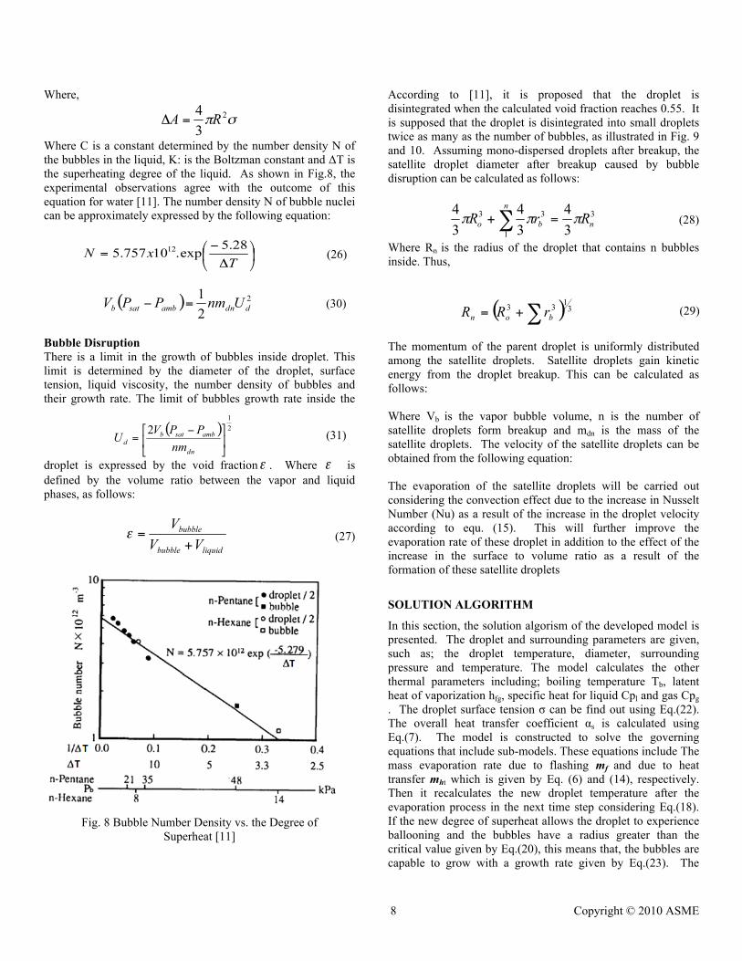
Where C is a constant determined by the number density N of the bubbles in the liquid, K: is the Boltzman constant and ΔT is the superheating degree of the liquid. As shown in Fig.8, the experimental observations agree with the outcome of this equation for water [11]. The number density N of bubble nuclei can be approximately expressed by the following equation:
(26)
Bubble Disruption There is a limit in the growth of bubbles inside droplet. This limit is determined by the diameter of the droplet, surface tension, liquid viscosity, the number density of bubbles and their growth rate. The limit of bubbles growth rate inside the
droplet is expressed by the void fraction . Where is defined by the volume ratio between the vapor and liquid phases, as follows:
(27)
Fig. 8 Bubble Number Density vs. the Degree of
Superheat [11]
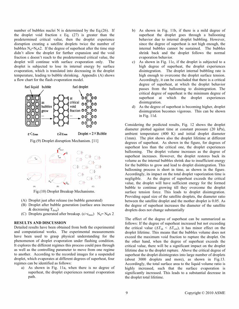
According to [11], it is proposed that the droplet is disintegrated when the calculated void fraction reaches 0.55. It is supposed that the droplet is disintegrated into small droplets twice as many as the number of bubbles, as illustrated in Fig. 9 and 10. Assuming mono-dispersed droplets after breakup, the satellite droplet diameter after breakup caused by bubble disruption can be calculated as follows:
(28)
Where Rn is the radius of the droplet that contains n bubbles inside. Thus,
(29)
The momentum of the parent droplet is uniformly distributed among the satellite droplets. Satellite droplets gain kinetic energy from the droplet breakup. This can be calculated as follows: Where Vb is the vapor bubble volume, n is the number of satellite droplets form breakup and mdn is the mass of the satellite droplets. The velocity of the satellite droplets can be obtained from the following equation: The evaporation of the satellite droplets will be carried out considering the convection effect due to the increase in Nusselt Number (Nu) as a result of the increase in the droplet velocity according to equ. (15). This will further improve the evaporation rate of these droplet in addition to the effect of the increase in the surface to volume ratio as a result of the formation of these satellite droplets
SOLUTION ALGORITHM
In this section, the solution algorism of the developed model is presented. The droplet and surrounding parameters are given, such as; the droplet temperature, diameter, surrounding pressure and temperature. The model calculates the other thermal parameters including; boiling temperature Tb, latent heat of vaporization hfg, specific heat for liquid Cpl and gas Cpg . The droplet surface tension σ can be find out using Eq.(22). The overall heat transfer coefficient αs is calculated using Eq.(7). The model is constructed to solve the governing equations that include sub-models. These equations include The mass evaporation rate due to flashing mf and due to heat transfer mht which is given by Eq. (6) and (14), respectively. Then it recalculates the new droplet temperature after the evaporation process in the next time step considering Eq.(18). If the new degree of superheat allows the droplet to experience ballooning and the bubbles have a radius greater than the critical value given by Eq.(20), this means that, the bubbles are capable to grow with a growth rate given by Eq.(23). The
(30)
(31)
9 Copyright © 2010 ASME
number of bubbles nuclei N is determined by the Eq.(26). If the droplet void fraction ε Eq. (27) is greater than the predetermined critical value, then the droplet experience disruption creating a satellite droplets twice the number of bubbles Nd=Nbx2. If the degree of superheat after the time step didn’t allow the droplet for further expansion and the void fraction ε doesn’t reach to the predetermined critical value, the droplet will continue with surface evaporation only. The droplet is subjected to lose its internal energy by surface evaporation, which is translated into decreasing in the droplet temperature, leading to bubble shrinking. Appendix (A) shows a flow chart for the flash evaporation model.
Fig.(9) Droplet disruption Mechanism. [11]
Fig.(10) Droplet Breakup Mechanisms.
(A) Droplet just after release (no bubble generated) (B) Droplet after bubble generation (surface area increase
& decreasing Tdrop) (C) Droplets generated after breakup. (ε>εmax) Nd= NBx 2
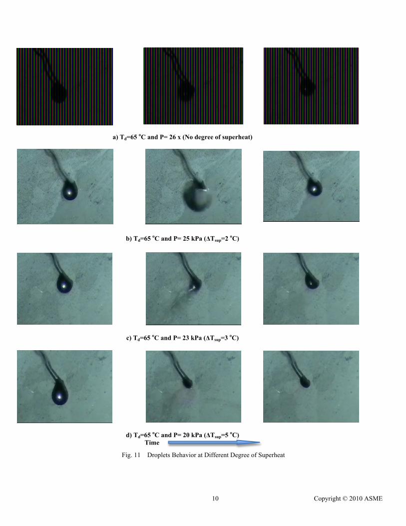
RESULTS AND DISCUSSION Detailed results have been obtained from both the experimental and computational works. The experimental measurements have been used to grasp physical understanding for the phenomenon of droplet evaporation under flashing condition. It explores the different regimes this process could pass through as well as the controlling parameter to move from one regime to another. According to the recorded images for a suspended droplet, which evaporates at different degrees of superheat, four regimes can be identified as follows:
a) As shown in Fig. 11a, when there is no degree of superheat, the droplet experiences normal evaporation path.
b) As shown in Fig. 11b, if there is a mild degree of superheat the droplet goes through a ballooning behavior due to internal droplet bubbling. However, since the degree of superheat is not high enough, the internal bubbles cannot be sustained. The bubbles shrink back and the droplet follows the normal evaporation behavior.
c) As shown in Fig. 11c, if the droplet is subjected to a high degree of superheat, the droplet experiences disintegration. The droplet internal bubbling rate is high enough to overcome the droplet surface tension. Accordingly, it can be concluded that there is a critical degree of superheat, at which the droplet behavior passes from the ballooning to disintegration. The critical degree of superheat is the minimum degree of superheat at which the droplet experiences disintegration.
d) As the degree of superheat is becoming higher, droplet disintegration becomes vigorous. This can be shown in Fig. 11d.
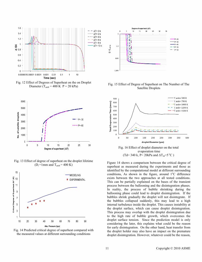
Considering the predicted results, Fig. 12 shows the droplet diameter plotted against time at constant pressure (20 kPa), ambient temperature (400 K) and initial droplet diameter (1mm). The plot shows also the droplet lifetime at different degrees of superheat. As shown in the figure, for degrees of superheat less than the critical one, the droplet experiences ballooning. The droplet volume increases as the degree of superheat increases. However, the droplet restores back its volume as the internal bubbles shrink due to insufficient energy for the bubbles to grow and lead to droplet disintegration. This ballooning process is short in time, as shown in the figure. Accordingly, its impact on the total droplet vaporization time is negligible. As the degree of superheat exceeds the critical value, the droplet will have sufficient energy for the formed bubble to continue growing till they overcome the droplet surface tension force. This leads to droplet disintegration. Providing equal size of the satellite droplets, the diameter ratio between the satellite droplet and the mother droplet is 0.05. As the degree of superheat increases the diameter of the satellite droplets does not change substantially The effect of the degree of superheat can be summarized as follows: If the degree of superheat increased but not exceeding the critical value (ΔTsh < ΔTcrit), it has minor effect on the droplet lifetime. This means that the bubbles volume does not exceed the maximum void fraction to rupture the droplet. On the other hand, when the degree of superheat exceeds the critical value, there will be a significant impact on the droplet lifetime due to the droplet rupture. Above the critical degree of superheat the droplet disintegrates into large number of droplets (about 3000 droplets and more), as shown in Fig.13. Accordingly, the total surface area to the liquid volume ratio is highly increased, such that the surface evaporation is significantly increased. This leads to a substantial decrease in the droplet total lifetime.
10 Copyright © 2010 ASME
a) Td=65 oC and P= 26 x (No degree of superheat)
b) Td=65 oC and P= 25 kPa (ΔTsup=2 oC)
c) Td=65 oC and P= 23 kPa (ΔTsup=3 oC)
d) Td=65 oC and P= 20 kPa (ΔTsup=5 oC) Time
Fig. 11 Droplets Behavior at Different Degree of Superheat
11 Copyright © 2010 ASME
Fig. 12 Effect of Degrees of Superheat on the on Droplet
Diameter (Tamb = 400 K P = 20 kPa)
Fig. 13 Effect of degree of superheat on the droplet lifetime (Di =1mm and Tamb = 400 K)
Fig. 14 Predicted critical degree of superheat compared with
the measured values at different surrounding conditions
Fig. 15 Effect of Degree of Superheat on The Number of The
Satellite Droplets
Fig. 16 Effect of droplet diameter on the total
evaporation time (Td= 340 k, P= 20kPa and ΔTsh=5 oC )
Figure 14 shows a comparison between the critical degree of superheat as measured during the experiments and those as identified by the computational model at different surrounding conditions, As shown in the figure, around 1oC difference exists between the two approaches at all tested conditions. This can be partially explained on the bases of the transient process between the ballooning and the disintegration phases. In reality, the process of bubble shrinking during the ballooning phase could lead to droplet disintegration. If the bubbles shrink gradually the droplet will not disintegrate. If the bubbles collapsed suddenly, this may lead to a high internal turbulence inside the droplet. This causes instability at the droplet surface, which can cause droplet disintegration. This process may overlap with the droplet disintegration due to the high rate of bubble growth, which overcomes the droplet surface tension. Since the prediction model is only considering the later, this explains what could be the reason for early disintegration. On the other hand, heat transfer from the droplet holder may also have an impact on the premature droplet disintegration. However, whatever could be the reason,

12 Copyright © 2010 ASME
the experiments proofed that the model accuracy is acceptable. The figure shows also the effect of the surrounding pressure on the critical degree of superheat at which the droplet disintegrates. As the surrounding pressure increases the critical degree of superheat increases. This may be controlled by different mechanisms. As the surrounding pressure increases, the droplet is confined such that it keeps its integrity by increasing the external force exerted on the droplet. This leads to droplet disintegration at higher degree of superheat. However, the latent heat of vaporization as well as surface tension is decreased as the surrounding pressure increases, which can lead to earlier droplet disintegration. Yet, it seems that the external force has more dominant effect on the droplet behavior. Figure 15 shows the predicted results regarding the effect of degree of superheat on the normalized droplet evaporation time. The normalized droplet evaporation time is the evaporation time of the parent droplet addition to the evaporation time of the satellite droplets, in case of droplet disintegration divided by the evaporation time of the original droplet under the same surrounding conditions but at zero degree of superheat. As shown in the figure, there is no change in the droplet evaporation time at low degrees of superheat. As the droplet reaches the critical degree of superheat, substantial reduction in the evaporation time is achieved. This may approach values of two orders of magnitude less than that of the original droplet at zero degree of superheat. This is attributed to droplet disintegration and consequently the substantial increase in the surface to volume ratio. As shown in the figure as the droplet degree of superheat is further exceeded the critical value, minor improvement occurs (i.e. reduction in the evaporation time). Figure 16 shows the prediction for the effect of the droplet diameter on the total evaporation time at constant degree of superheat. The figure shows that, at small droplets size the droplet lifetime increases rapidly as the diameter increases until reaching a critical diameter. Where the droplet keeps its integrity and the classical heat transfer is the controlling mechanism for droplet evaporation. Above the critical value of the droplet diameter, the droplet disintegrates into large number of satellite droplets. This decreases the total droplet lifetime due to the increase in the surface to volume ratio. Furthermore, the gained kinetic energy by the satellite droplets due to the disintegration process enhances the evaporation process. Therefore, it is important to find out the critical diameter at each degree of superheat. CONCLUSIONS From the experimental and computational results it can be concluded that; four grimes for a droplet evaporating under flashing conditions are identified. The transition from one regime to another depends on the droplet degree of superheat in comparison with the critical degree of superheat. For no degree of superheat the droplet goes normal evaporation
mode. In case if the degree of superheat is less than the critical value, the droplet shall go mild internal bubbling, leading to droplet ballooning. Since the degree of superheat is not enough the bubbles are shrunk back leading to normal droplet evaporation pattern and the droplet preserves its integrity. In case if the degree of superheat exceeds the critical value, the droplet evaporation will have vigorous internal bubbling leading to droplet disintegration. As droplet disintegration occurs, large numbers of satellite droplets are resulted leading to substantial increase in the total liquid surface to volume ratio. This enhances droplet evaporation rate to several degrees in order. This is further enhanced due to the high kinetic energy of the satellite droplets due to the violent disintegration. The intensity of the disintegration increases as the degree of super heat increases. The developed computational model expresses the phenomenon as well as the aforementioned regimes accurately. This phenomenon could have many practical applications through improving atomization characteristics. These applications may include; direct injection combustion engine, inlet duct cooling for gas turbines, rocket engines, spray cooling and spray painting. NOMENCLATURE Symbol
Definition
Cp Specific heat [W/kg K] h Enthalpy [W/kg] k Thermal conductivity, [W/m.K]. L Latent heat [J/kg] mo Mass flow rate, [kg/sec]. Nu Nusselt Number Q Heat flow [W P Pressure, [Pa]. Pr Prandtl Number T Temperature, [K] r Radial distance [m] R Radius [m] Re Reynolds Number V Velocity, [m/sec]. W Work [J] ρ Density, [kg/m3]. σ Surface tension, [N/m]. Subscripts
B Boiling C Critical D Droplet F Flashing ht Heat Transfer i Initial l Liquid Vap, v Vapor s, sat Saturation ∞ Ambient

13 Copyright © 2010 ASME
REFERENCES [1] Iyengar, V., Simmons, H., Ranson, D. and
Halzschuh, T., ”Flash Atomization, a New concept to Control Combustion Instability in water Injected Gas Turbine” ASME, GT 22375, Glasgow, 2010.
[2] Hirayasu, H.. “Spray Breakup Mechanism from the Hole-Type and Its Applications” J. of the Inst. For Liquid Atomization and Spray System, Vo;.10, pp 511-527, May-Oct. 2000.
[3] Gemci, T., Yakut, K., Chigier, N., Ho,T.C., “Experimental study of flash atomization of binary hydrocarbon liquids”, International Journal of Multiphase Flow, 2004.
[4] Bowen, Ph. J. ”Flashing liquid jets and two-phase dispersion-A review”, Health and Safety Executive, 2003.
[5] Saury, D., Harmand, S., Siroux, M., “Experimental study of flash evaporation of a water film”, International Journal of Heat and Mass Transfer , 3447–3457, 2002.
[6] Baifang Zuo, A.M.Gomes, C.J.Rutland, “Studies of Superheated Fuel Spray Structures and Vaporization in GDI Engines”, Engine Research Centre, University of Wisconsin ,2003.
[7] Schmehl, R., Steelant, J., “Flash-evaporation of oxidizer spray during start-up of an upper-stage rocket engine”, European Space Agency, 39th AIAA/ASME/SAE/ASEE, 2003.
[8] El-Kholy, A. H., ”Study of the Effect of Flash Evaporation on Droplets and Sprays Under Different Operating Conditions:, M.Sc Thesis, Helwan University, 2010.
[9] Nikolay, I., “Multiphase Flow Dynamics” Springer-Verlag Berlin Heidelberg, 2nd edition, 2005.
[10] Sher, D., Kohany, T., Rashkovan, A., “Flash-boiling atomization”, Energy and Combustion Science, pp. 417–439, 2008.
[11] Daisuke, K., Hajime, I., Hisakazu, S., Yuichi, G., Matsuo, O., Jiro S., “Numerical Study on Flash-Boiling Spray of Multi-component Fuel”, Science and Technology(Japan), No. (C)(2)14550874, 2006
Appendix (A)
App. 1 Flow Chart for Flash Evaporation Model
Copyright © 2022 FDOKUMEN