COMPUTATIONAL ANALYSIS OF AERODYNAMIC ...
18
COMPUTATIONAL ANALYSIS OF AERODYNAMIC PARAMETERS FOR SUPERSONIC ARTILLERY PROJECTILES MD RAFIQUR RAHMAN DEPARTMENT OF MECHANICAL ENGINEERING , MILITARY INSTITUTE OF SCIENCE AND TECHNOLOGY, MIRPUR CANTONMENT, DHAKA, BANGLADESH ABSTRACT Aerodynamic parameters have a huge impact on the trajectory of a projectile which in turn results in its range and accuracy. The influence aerodynamic parameters for the estimation of trajectory elements are drag Coefficients, lift Coefficients, angles of attack, muzzle velocity, atmospheric conditions, and the projectile shape and size. Thus proper methods for determining the drag and lift forces of the projectile is very important. The trajectory of a projectile through the air is affected both by gravity and by aerodynamic forces. In this paper 57 mm and 37 mm anti aircraft projectile was considered for the analysis. Here main emphasis was given to determine pressure coefficient, Drag coefficients, lift coefficient of the projectiles at different angle of attack. To study the aerodynamic parameters the experiment was conducted in an open circuit subsonic wind tunnel where uniform flow velocity is maintained across the flow direction. For the experiment varied angles of the attack was considered. Here inclined manometer was used to find out the surface static pressure and the pressure coefficient was determined from that. Then the drag & lift forces and their coefficients was determined. Finally, for the computational analysis, the ANSYS Software was used to simulate the experimental data. KEYWORDS Aerodynamic Parameters, Projectile, Drag Force, Lift Force, Pressure Coefficient, Drag Coefficient, Lift Coefficient, Angle of Attack, Computational analysis, Ansys software, 1. INTRODUCTION Accurate experimental methods for determining the aerodynamic parameters of the projectile is very important. In modern warfare, the design of the projectiles is largely focused on its range and accuracy. Aerodynamics forces have a huge impact on the trajectory of a projectile. The influence Parameters for the estimation of trajectory elements are drag Coefficients, lift Coefficients, angles of attack, muzzle velocity, atmospheric conditions, and the projectile shape and size. When a projectile is launched it experiences some aerodynamic parameters which is more than the gravitational force. These parameters depend on the angles of attack, the nose shape, velocity, and surface smoothness of the projectile. However, the drag experienced by a single projectile will be different from the drag force experienced by two projectiles flying side IJRDO - Journal Of Mechanical And Civil Engineering ISSN: 2456-1479 Volume-6 | Issue-8 | August, 2020 1
-
Upload
khangminh22 -
Category
Documents
-
view
1 -
download
0
Transcript of COMPUTATIONAL ANALYSIS OF AERODYNAMIC ...
COMPUTATIONAL ANALYSIS OF AERODYNAMIC
PARAMETERS FOR SUPERSONIC ARTILLERY
PROJECTILES
MD RAFIQUR RAHMAN
DEPARTMENT OF MECHANICAL ENGINEERING , MILITARY INSTITUTE
OF SCIENCE AND TECHNOLOGY, MIRPUR CANTONMENT, DHAKA,
BANGLADESH
ABSTRACT
Aerodynamic parameters have a huge impact on the trajectory of a projectile which in
turn results in its range and accuracy. The influence aerodynamic parameters for the estimation
of trajectory elements are drag Coefficients, lift Coefficients, angles of attack, muzzle velocity,
atmospheric conditions, and the projectile shape and size. Thus proper methods for determining
the drag and lift forces of the projectile is very important. The trajectory of a projectile through
the air is affected both by gravity and by aerodynamic forces. In this paper 57 mm and 37 mm
anti aircraft projectile was considered for the analysis. Here main emphasis was given to
determine pressure coefficient, Drag coefficients, lift coefficient of the projectiles at different
angle of attack. To study the aerodynamic parameters the experiment was conducted in an open
circuit subsonic wind tunnel where uniform flow velocity is maintained across the flow
direction. For the experiment varied angles of the attack was considered. Here inclined
manometer was used to find out the surface static pressure and the pressure coefficient was
determined from that. Then the drag & lift forces and their coefficients was determined. Finally,
for the computational analysis, the ANSYS Software was used to simulate the experimental
data.
KEYWORDS
Aerodynamic Parameters, Projectile, Drag Force, Lift Force, Pressure Coefficient, Drag
Coefficient, Lift Coefficient, Angle of Attack, Computational analysis, Ansys software,
1. INTRODUCTION
Accurate experimental methods for determining the aerodynamic parameters of the projectile
is very important. In modern warfare, the design of the projectiles is largely focused on its
range and accuracy. Aerodynamics forces have a huge impact on the trajectory of a projectile.
The influence Parameters for the estimation of trajectory elements are drag Coefficients, lift
Coefficients, angles of attack, muzzle velocity, atmospheric conditions, and the projectile shape
and size. When a projectile is launched it experiences some aerodynamic parameters which is
more than the gravitational force. These parameters depend on the angles of attack, the nose
shape, velocity, and surface smoothness of the projectile. However, the drag experienced by a
single projectile will be different from the drag force experienced by two projectiles flying side
IJRDO - Journal Of Mechanical And Civil Engineering ISSN: 2456-1479
Volume-6 | Issue-8 | August, 2020 1
by side since the disturbance created in the flow field by one projectile will affect the other
one. These parameters are the prime reason for reducing projectile velocity and accuracy.
Therefore, it is very important to determine and minimize the effect of drag and lift .
In this paper both experimental and computational analysis are done on projectiles.
Here good agreements between computational analysis and experimental observations are
obtained where the coefficient of drag and lift are obtained at different speed and different
angle of attack. We have considered two different types of Projectiles i.e 57 mm and 37 mm
anti-aircraft projectiles in the present study to emphasis on determining the pressure Coefficient
from the surface static pressure. Then other parameters i.e drag & lift forces and its Coefficient
at various angles of attack was determined. Here the experiment was done in subsonic wind
tunnel and computational analysis was done through Ansys software.
2. REVIEW OF LITERATURE
Many studies and researches are performed at the past to study the aerodynamic
parameters for various types of projectiles. All those researches are essential as any findings
will help in the overall projectiles aerodynamic characteristics and its performances.
Mohammad Amin et al. [1] prepared an article that focused on the study of various
methods for reducing the base drag of artillery projectiles caliber 122mm. The computational
fluid dynamics (CFD) numerical simulations (RANS, 2-D axisymmetric configuration) were
performed, to investigate the base drag characteristics of the projectiles. Chand et al. [2]
discussed in their paper the feasibility of the application of the system dynamics approach in
the artillery projectile motion analysis under the test and evaluation curriculum activities using
a point-mass mathematical model. Goran et al. [3] present the modification of the existing
guided missile in their study. The modification was performed based on required aerodynamic
coefficients for the existing guided missile. The preliminary aerodynamic configurations of the
improved missile front parts were designed based on theoretical and computational fluid
dynamics simulations. Sahoo et al. [4] in their study, made a numerical estimation of the drag
variation and trajectory elements of a supersonic projectile having two different nose shapes.
The coefficient of drag (CD) obtained from the simulation is used as an input parameter for the
estimation of trajectory elements. The numerical results, i.e, the coefficient of drag at different
Mach numbers and trajectory elements are validated with the data recorded by tracking radar
from an experimental firing.
There are many more other study on this like Jian et al. [5] in their analysis shows a
hypersonic aerodynamics analysis of an electromagnetic gun launched projectile configuration
is undertaken to ameliorate the basic aerodynamic characteristics in comparison with the
regular projectile layout. With a steady-state computational fluid dynamics (CFD) simulation,
the basic density, pressure, and velocity contours of the EM gun projectile flow field at Mach
number 5.0, 6.0, and 7.0 (angle of attack= 0o) have been analyzed. Mahfouz et al. [6] in their
study applied computational fluid dynamics (CFD) to simulate a 2-D hollow projectile with
optimal geometry at different Mach numbers at 1 < Ma < 1.8 and different angles of attack
to investigate the shock wave structures and drag characteristics. Shubham et al. [7] presented
IJRDO - Journal Of Mechanical And Civil Engineering ISSN: 2456-1479
Volume-6 | Issue-8 | August, 2020 2
in their paper steady-state, two-dimensional computational investigations performed on NACA
0012 airfoil to analyze the effect of variation in Reynolds number on the aerodynamics of the
airfoil without and with a Gurney flap. Both lift and drag coefficients increase with Gurney
flap compared to those without Gurney flap at all Reynolds numbers at all angles of attack.
Damir et al. [8] shows in this paper the research of aerodynamic characteristics of classic
symmetric projectile. On the basis of constructed parameters and dynamic characteristics of 40
mm projectile model it calculates aerodynamic coefficients and their derivatives. Kiran et al.
[9] Investigated in their research the aerodynamic properties of a standard M549, 155mm
projectile. The detailed study was done and validated to reduce drag and to see its effect on the
projectile design for both transonic and supersonic speeds.
3. EXPERIMENT
The experiment will be conducted in an open circuit subsonic wind tunnel. The
experiment comprises the measurement of aerodynamic parameters of the model in the wind
tunnel. The wind tunnel has a bell mouth entry, a flow Straightener, diverging section, and two
axial flow fans. The projectile will be placed at the exit end of the wind tunnel. A set of dummy
37 mm and 57 mm projectiles will be considered for the experiment. The dimensions are
collected from the commonly used shell . At different angles of attack (30o to 50o) the static
pressure measurement will be made. The speed of the tunnel (4.7 m/s) will be maintained at
maximum to simulate the actual flow experienced by projectile. From the static pressure
distributions, using numerical computations, the drag and lift coefficients will be measured and
compared for different size and flow configuration. For numerical scheme the ANSYS software
will be used to simulate the experiment .
3.1. Requirement of Model study
There are roughly four classes of techniques to predict aerodynamic parameters on a
projectile in atmospheric flight. These are empirical methods, wind tunnel testing,
computational fluid dynamics simulation, and spark range testing. In computational fluid
dynamic (CFD) simulations, the fundamental fluid dynamic equations are numerically solved
for a specific configuration. Wind tunnels testing and full-scale results are always different due
to Reynold's number inequality. In most of the wind tunnel test, the full-scale Reynolds number
is difficult to achieve.
For determining aerodynamic Coefficient data including the total aerodynamic drag and
lift, studies with the model and full-scale projectile are performed to validate the model. But
full-scale experiments are both costly and difficult to perform. For the present study with anti-
aircraft artillery projectiles, full-scale experiments will be a complex and costly. At the same
time it will be difficult to record reliable pressure distribution simultaneously on the single as
well as a group of the projectile as there will be a variation of speeds and direction of the wind
with time. The flow around projectile in the actual environment is very complex and
formulation of a mathematical model to predict the flow is almost impossible. Thus for solution
accuracy model study of anti-aircraft artillery & tank projectile and various data obtained from
the simulation will become very handy for practical analysis.
IJRDO - Journal Of Mechanical And Civil Engineering ISSN: 2456-1479
Volume-6 | Issue-8 | August, 2020 3

3.2. Preparation of the Model (Dummy Projectile)
Projectiles of existing anti-aircraft Artillery which are used in worldwide were selected
for the preparation of the model. For this study projectiles of existing 37 mm and 57 mm was
used for the preparation of the model. We have prepared the dummy model by wood instead
of metal because with the metal the dummy model will be heavier and will be difficult to use
during the experiment. So each of the models was made of seasoned teak wood to avoid
bucking and expansion due to the change in weather. Wooden dummy model is shown in
Figure 1 . The dimensions of the 37 mm and 57 mm projectiles are shown in Figure 2. Dummy
projectile contained 10 tapping point for 37 mm projectile and 17 tapping points for 57 mm
projectiles. The distance between the consecutive tapping points was equal as shown in the
figure . Inner Diameter of each tapping point is 1 mm.
The tapings were made along the circular-section of the projectiles. Since the velocity was two-
dimensional flow, this would not make any effect on the experimental result. Keeping the
outside of the projectiles intact the inside of the projectiles was made hollow through which
the plastic tubes were allowed to pass.
Figure 1 : Dummy Model of existing 37 mm & 57 mm Projectile
IJRDO - Journal Of Mechanical And Civil Engineering ISSN: 2456-1479
Volume-6 | Issue-8 | August, 2020 4

The plastic tubes were connected with the copper capillary tubes at one side and the other side
with the inclined multi-manometer. The tapings were made of copper tubes of 2 mm outside
diameter. Each tapping was of 50 mm length approximately. From the end of the copper tube
flexible plastic tube of 1.5 mm, inner diameter was press-fitted. The tapping positions on the
cross-section of the projectiles are shown in Figure 3.
In the experimental investigation, initial reading was taken placing the single projectile
in front of the wind tunnel shown in Figure 4. The wind velocity across the test section of the
wind tunnel was measured with the help of a digital anemometer. A pitot tube was also used to
measure the velocity to cross-check. The pitot tube was connected to an inclined manometer
and the limb of which contained manometer fluid. The surface static pressures were measured
with the help of an inclined manometer.
Figure 3 : Tapping position shown on Projectiles
Figure 2 : Dimensions shown in Dummy Projectiles
IJRDO - Journal Of Mechanical And Civil Engineering ISSN: 2456-1479
Volume-6 | Issue-8 | August, 2020 5

Figure 4: Experimental setup of projectile for measuring static pressure.
3.3. Experimental Conditions:
The static pressure was measured with a manometer and it had a minimum deflection
of 1 mm. The experimental conditions are shown in Table 1. A Computational Fluid Dynamics
(CFD) simulation was done with ANSYS Multiphysics software on similar conditions to
compare the experimental and simulation results.
Table 1. Experimental Conditions for Different Projectiles.
Projectile Size (mm) The angle of Attack,
AOA, (°) Air Velocity (m/s)
Number of Tapping
Points
37 30, 35, 40, 45, 50 4.7 10
57 30, 35, 40, 45, 50 4.7 17
4. Mathematical Model
For the study, from the wind tunnel pressure tap, static pressure at the upstream of the
test section was measured for calculating the lift and drag force. The inclined manometer was
used to measure the static pressure on the projectile surface. A constant Wind Velocity of the
Wind tunnel was chosen which was 4.7 m /s, measured directly with an anemometer which is
later used to calculate the drag, lift, and pressure coefficient.
IJRDO - Journal Of Mechanical And Civil Engineering ISSN: 2456-1479
Volume-6 | Issue-8 | August, 2020 6
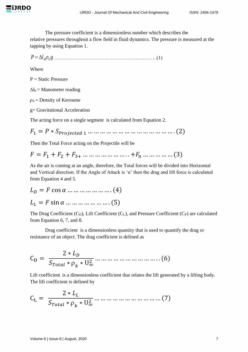
The pressure coefficient is a dimensionless number which describes the
relative pressures throughout a flow field in fluid dynamics. The pressure is measured at the
tapping by using Equation 1.
glP kk= ……………………………………………………..(1)
Where
P = Static Pressure
lk = Manometer reading
k = Density of Kerosene
g= Gravitational Acceleration
The acting force on a single segment is calculated from Equation 2.
𝐹1 = 𝑃 ∗ 𝑆𝑃𝑟𝑜𝑗𝑒𝑐𝑡𝑒𝑑 1 … … … … … … … … … … … … … … . (2)
Then the Total Force acting on the Projectile will be
𝐹 = 𝐹1 + 𝐹2 + 𝐹3+ … … … … … … … . . +𝐹𝑛 … … … … … (3)
As the air is coming at an angle, therefore, the Total forces will be divided into Horizontal
and Vertical direction. If the Angle of Attack is ‘α’ then the drag and lift force is calculated
from Equation 4 and 5.
𝐿𝐷 = 𝐹 cos 𝛼 … … … … … … … . (4)
𝐿𝐿 = 𝐹 sin 𝛼 … … … … … … … . (5)
The Drag Coefficient (CD), Lift Coefficient (CL), and Pressure Coefficient (CP) are calculated
from Equation 6, 7, and 8.
Drag coefficient is a dimensionless quantity that is used to quantify the drag or
resistance of an object. The drag coefficient is defined as
CD = 2 ∗ 𝐿𝐷
𝑆𝑇𝑜𝑡𝑎𝑙 ∗ 𝑘
∗ U∞2
… … … … … … … … … … . . (6)
Lift coefficient is a dimensionless coefficient that relates the lift generated by a lifting body.
The lift coefficient is defined by
CL = 2 ∗ 𝐿𝐿
𝑆𝑇𝑜𝑡𝑎𝑙 ∗ 𝑘
∗ U∞2
… … … … … … … … … … … (7)
IJRDO - Journal Of Mechanical And Civil Engineering ISSN: 2456-1479
Volume-6 | Issue-8 | August, 2020 7
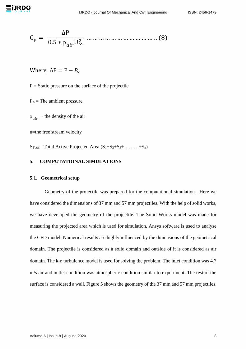
Cp = ∆P
0.5 ∗ 𝑎𝑖𝑟
U∞2
… … … … … … … … … … … . . (8)
Where, ∆P = P − 𝑃∝
P = Static pressure on the surface of the projectile
P = The ambient pressure
𝑎𝑖𝑟
= the density of the air
u=the free stream velocity
STotal= Total Active Projected Area (S1+S2+S3+………+Sn)
5. COMPUTATIONAL SIMULATIONS
5.1. Geometrical setup
Geometry of the projectile was prepared for the computational simulation . Here we
have considered the dimensions of 37 mm and 57 mm projectiles. With the help of solid works,
we have developed the geometry of the projectile. The Solid Works model was made for
measuring the projected area which is used for simulation. Ansys software is used to analyse
the CFD model. Numerical results are highly influenced by the dimensions of the geometrical
domain. The projectile is considered as a solid domain and outside of it is considered as air
domain. The k- turbulence model is used for solving the problem. The inlet condition was 4.7
m/s air and outlet condition was atmospheric condition similar to experiment. The rest of the
surface is considered a wall. Figure 5 shows the geometry of the 37 mm and 57 mm projectiles.
IJRDO - Journal Of Mechanical And Civil Engineering ISSN: 2456-1479
Volume-6 | Issue-8 | August, 2020 8
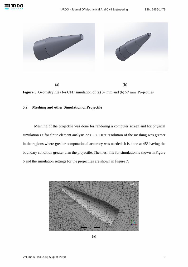
(a) (b)
Figure 5. Geometry files for CFD simulation of (a) 37 mm and (b) 57 mm Projectiles
5.2. Meshing and other Simulation of Projectile
Meshing of the projectile was done for rendering a computer screen and for physical
simulation i.e for finite element analysis or CFD. Here resolution of the meshing was greater
in the regions where greater computational accuracy was needed. It is done at 45° having the
boundary condition greater than the projectile. The mesh file for simulation is shown in Figure
6 and the simulation settings for the projectiles are shown in Figure 7.
(a)
IJRDO - Journal Of Mechanical And Civil Engineering ISSN: 2456-1479
Volume-6 | Issue-8 | August, 2020 9

(b)
The geometry of the projectiles with the same dimension of was put forward to
simulation with scale 1:1. The geometric model of the projectile is shown in Fig. No 5. The
projectile model was sketched on Solid Works 2017 then imported to ANSYS Geometry. The
boundary is C-type pattern with 10D at the upstream side and 15D at the downstream side from
the surface of the model where D is the diameter of the projectile.
(a) (b)
Figure 7 : Ansys CFD Simulation setting for (a) 37 mm and (b) 57 mm Projectiles.
Figure 6 : Mesh of the CFD Simulation for (a) 37 mm,
(b) 57 mm (zoomed) Projectiles
IJRDO - Journal Of Mechanical And Civil Engineering ISSN: 2456-1479
Volume-6 | Issue-8 | August, 2020 10

The air enters into the domain with a velocity of 4.7 m/s. The density of air was 1.225
kg/m3 and viscosity about 1.7894e-05 kg/m-s. At the outlet, the pressure outlet condition is
applied in the domain. The steady and incompressible flow of air is considered in this Analysis.
In these calculations, the second-order upwind scheme based on a multidimensional linear
reconstruction approach is used. These computations are carried out using FVM solver
(ANSYS FLUENT 2016), a commercial CFD package with a 3D double-precision
Configuration. The default convergence criterion in FLUENT is maintained. This criterion
requires that the scaled residuals decrease to 10-5.
6. Results and Discussion
Experimental test for two types of dummy projectile model was done for the
determination of aerodynamic parameters and for the determination of its characteristics at
various angle of attack. Here computational analysis was done to validate the experimental
results. From the wind tunnel primarily with the help of inclined manometer, the static pressure
on the surface of the projectiles at various angles of attack was taken, then the distribution of
the static pressure coefficients on the surface of the projectile is compared numerically. Finally,
the other aerodynamic parameters are also compared. Results for the CFD analysis of the
dummy projectile models are obtained during validation. The static pressure acting on the
projectiles are calculated from the inclined manometer, here friction of the projectile is not
considered in the experimental and simulated evaluation. But the surface friction has a
contribution to the drag force and lift forces. Combining the drag and lift forces acting on each
segment of the projectiles can determine the total force acting on the projectile.
Angle of Attack (Degree)
Figure 8 : Angle of Attack Vs Drag Force
30 35 40 45 50
-0.1
0.0
0.1
0.2
-0.1
0.0
0.1
0.2
37mm (Experiment)
37mm (Simulation)
Dra
g F
orc
e (
N)
57mm (Experiment)
57mm (Simulation)
IJRDO - Journal Of Mechanical And Civil Engineering ISSN: 2456-1479
Volume-6 | Issue-8 | August, 2020 11
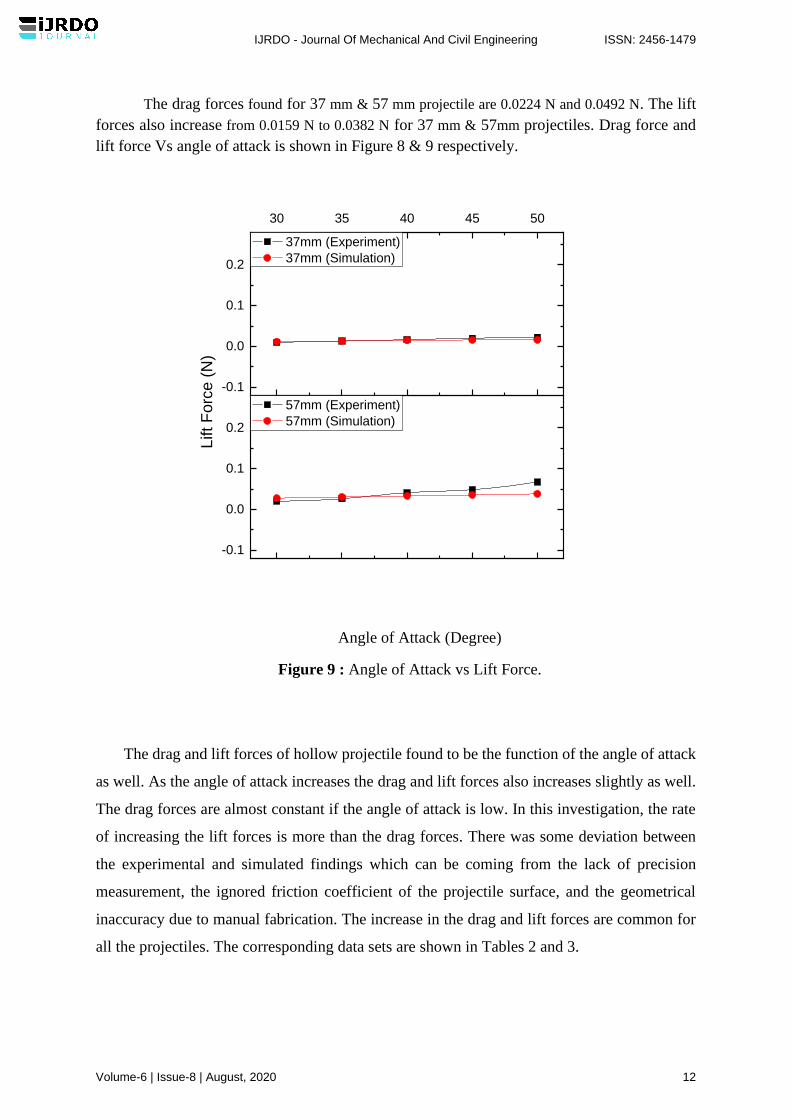
The drag forces found for 37 mm & 57 mm projectile are 0.0224 N and 0.0492 N. The lift
forces also increase from 0.0159 N to 0.0382 N for 37 mm & 57mm projectiles. Drag force and
lift force Vs angle of attack is shown in Figure 8 & 9 respectively.
Angle of Attack (Degree)
Figure 9 : Angle of Attack vs Lift Force.
The drag and lift forces of hollow projectile found to be the function of the angle of attack
as well. As the angle of attack increases the drag and lift forces also increases slightly as well.
The drag forces are almost constant if the angle of attack is low. In this investigation, the rate
of increasing the lift forces is more than the drag forces. There was some deviation between
the experimental and simulated findings which can be coming from the lack of precision
measurement, the ignored friction coefficient of the projectile surface, and the geometrical
inaccuracy due to manual fabrication. The increase in the drag and lift forces are common for
all the projectiles. The corresponding data sets are shown in Tables 2 and 3.
30 35 40 45 50
-0.1
0.0
0.1
0.2
-0.1
0.0
0.1
0.2
37mm (Experiment)
37mm (Simulation)
Lift F
orc
e (
N)
57mm (Experiment)
57mm (Simulation)
IJRDO - Journal Of Mechanical And Civil Engineering ISSN: 2456-1479
Volume-6 | Issue-8 | August, 2020 12
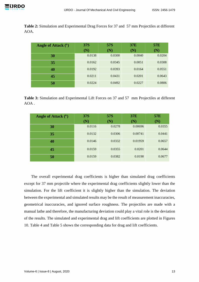
Table 2: Simulation and Experimental Drag Forces for 37 and 57 mm Projectiles at different
AOA.
Angle of Attack () 37S
(N)
57S
(N)
37E
(N)
57E
(N)
30 0.0138 0.0300 0.0040 0.0204
35 0.0162 0.0345 0.0051 0.0308
40 0.0192 0.0393 0.0164 0.0551
45 0.0211 0.0431 0.0201 0.0643
50 0.0224 0.0492 0.0227 0.0806
Table 3: Simulation and Experimental Lift Forces on 37 and 57 mm Projectiles at different
AOA .
Angle of Attack () 37S
(N)
57S
(N)
37E
(N)
57E
(N)
30 0.0116 0.0278 0.00696 0.0355
35 0.0132 0.0306 0.00741 0.0441
40 0.0146 0.0332 0.01959 0.0657
45 0.0159 0.0355 0.0201 0.0644
50 0.0159 0.0382 0.0190 0.0677
The overall experimental drag coefficients is higher than simulated drag coefficients
except for 37 mm projectile where the experimental drag coefficients slightly lower than the
simulation. For the lift coefficient it is slightly higher than the simulation. The deviation
between the experimental and simulated results may be the result of measurement inaccuracies,
geometrical inaccuracies, and ignored surface roughness. The projectiles are made with a
manual lathe and therefore, the manufacturing deviation could play a vital role is the deviation
of the results. The simulated and experimental drag and lift coefficients are plotted in Figures
10. Table 4 and Table 5 shows the corresponding data for drag and lift coefficients.
IJRDO - Journal Of Mechanical And Civil Engineering ISSN: 2456-1479
Volume-6 | Issue-8 | August, 2020 13
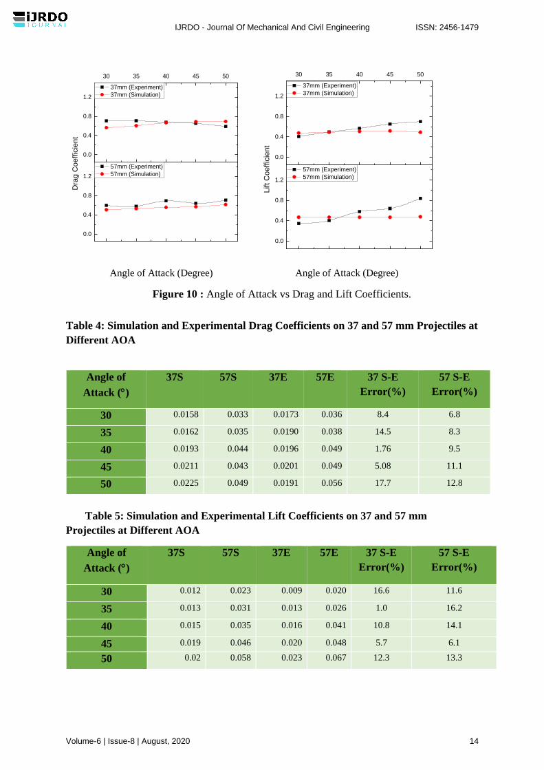
Angle of Attack (Degree) Angle of Attack (Degree)
Figure 10 : Angle of Attack vs Drag and Lift Coefficients.
Table 4: Simulation and Experimental Drag Coefficients on 37 and 57 mm Projectiles at
Different AOA
Angle of
Attack ()
37S 57S 37E 57E 37 S-E
Error(%)
57 S-E
Error(%)
30 0.0158 0.033 0.0173 0.036 8.4 6.8
35 0.0162 0.035 0.0190 0.038 14.5 8.3
40 0.0193 0.044 0.0196 0.049 1.76 9.5
45 0.0211 0.043 0.0201 0.049 5.08 11.1
50 0.0225 0.049 0.0191 0.056 17.7 12.8
Table 5: Simulation and Experimental Lift Coefficients on 37 and 57 mm
Projectiles at Different AOA
Angle of
Attack ()
37S 57S 37E 57E 37 S-E
Error(%)
57 S-E
Error(%)
30 0.012 0.023 0.009 0.020 16.6 11.6
35 0.013 0.031 0.013 0.026 1.0 16.2
40 0.015 0.035 0.016 0.041 10.8 14.1
45 0.019 0.046 0.020 0.048 5.7 6.1
50 0.02 0.058 0.023 0.067 12.3 13.3
30 35 40 45 50
0.0
0.4
0.8
1.2
0.0
0.4
0.8
1.2
37mm (Experiment)
37mm (Simulation)
Dra
g C
oeffic
ient
57mm (Experiment)
57mm (Simulation)
30 35 40 45 50
0.0
0.4
0.8
1.2
0.0
0.4
0.8
1.2
37mm (Experiment)
37mm (Simulation)
Lift C
oeffic
ient
57mm (Experiment)
57mm (Simulation)
IJRDO - Journal Of Mechanical And Civil Engineering ISSN: 2456-1479
Volume-6 | Issue-8 | August, 2020 14
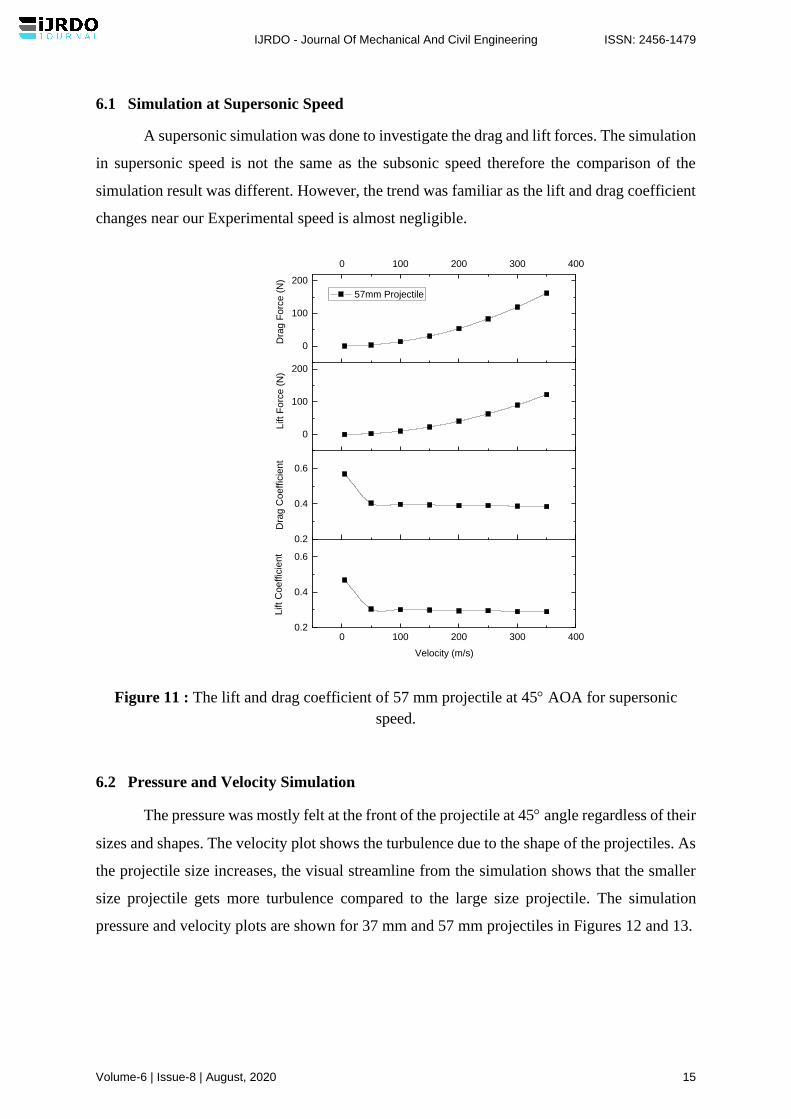
6.1 Simulation at Supersonic Speed
A supersonic simulation was done to investigate the drag and lift forces. The simulation
in supersonic speed is not the same as the subsonic speed therefore the comparison of the
simulation result was different. However, the trend was familiar as the lift and drag coefficient
changes near our Experimental speed is almost negligible.
Figure 11 : The lift and drag coefficient of 57 mm projectile at 45 AOA for supersonic
speed.
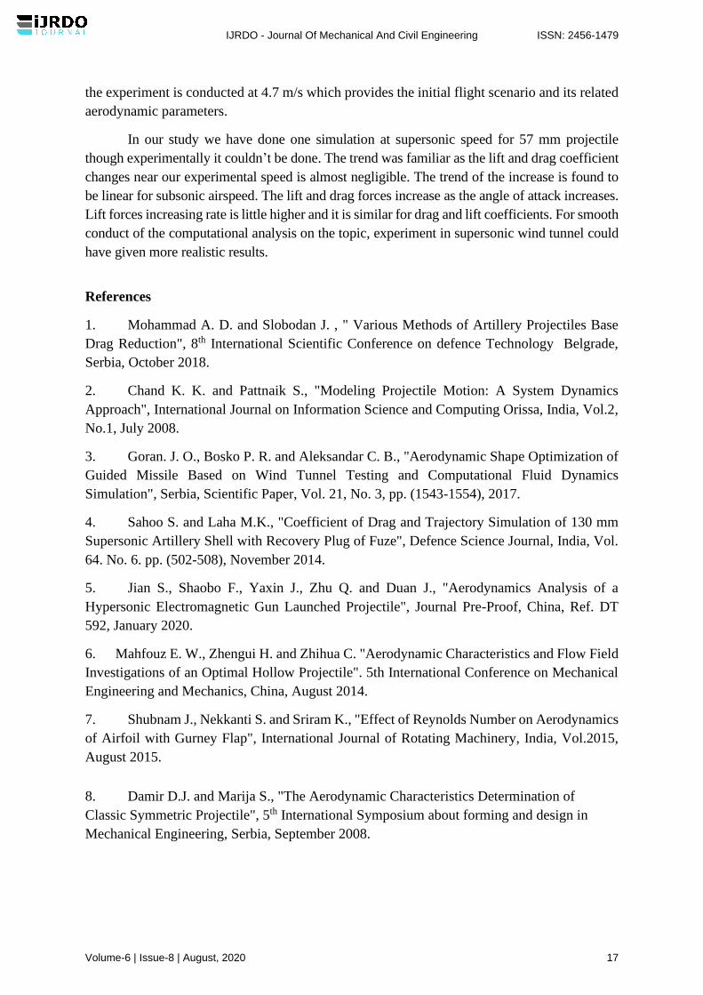
6.2 Pressure and Velocity Simulation
The pressure was mostly felt at the front of the projectile at 45 angle regardless of their
sizes and shapes. The velocity plot shows the turbulence due to the shape of the projectiles. As
the projectile size increases, the visual streamline from the simulation shows that the smaller
size projectile gets more turbulence compared to the large size projectile. The simulation
pressure and velocity plots are shown for 37 mm and 57 mm projectiles in Figures 12 and 13.
0 100 200 300 400
0
100
200
0
100
200
0.2
0.4
0.6
0 100 200 300 4000.2
0.4
0.6
Dra
g F
orc
e (
N)
57mm Projectile
Lift
Fo
rce (
N)
Dra
g C
oeff
icie
nt
Lift
Coe
ffic
ient
Velocity (m/s)
IJRDO - Journal Of Mechanical And Civil Engineering ISSN: 2456-1479
Volume-6 | Issue-8 | August, 2020 15
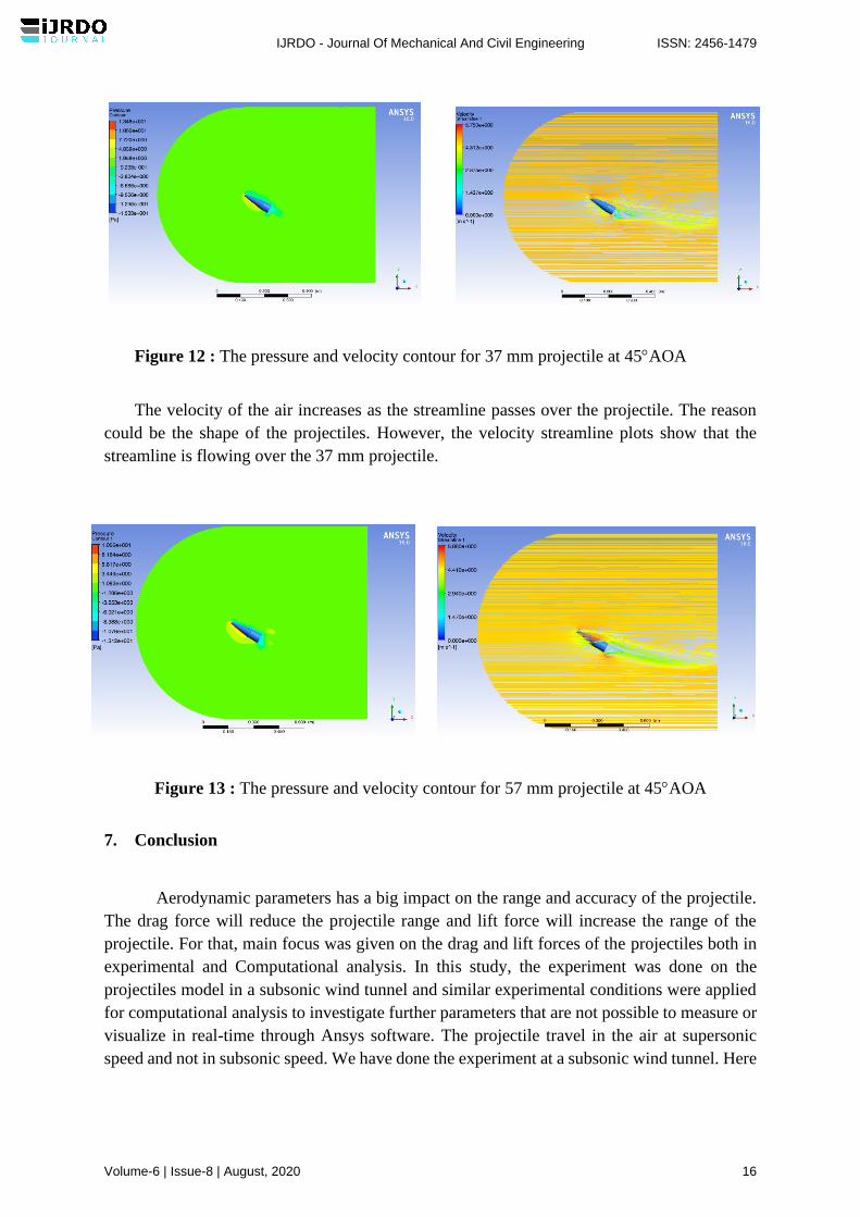
Figure 12 : The pressure and velocity contour for 37 mm projectile at 45AOA
The velocity of the air increases as the streamline passes over the projectile. The reason
could be the shape of the projectiles. However, the velocity streamline plots show that the
streamline is flowing over the 37 mm projectile.
Figure 13 : The pressure and velocity contour for 57 mm projectile at 45AOA
7. Conclusion
Aerodynamic parameters has a big impact on the range and accuracy of the projectile.
The drag force will reduce the projectile range and lift force will increase the range of the
projectile. For that, main focus was given on the drag and lift forces of the projectiles both in
experimental and Computational analysis. In this study, the experiment was done on the
projectiles model in a subsonic wind tunnel and similar experimental conditions were applied
for computational analysis to investigate further parameters that are not possible to measure or
visualize in real-time through Ansys software. The projectile travel in the air at supersonic
speed and not in subsonic speed. We have done the experiment at a subsonic wind tunnel. Here
IJRDO - Journal Of Mechanical And Civil Engineering ISSN: 2456-1479
Volume-6 | Issue-8 | August, 2020 16
the experiment is conducted at 4.7 m/s which provides the initial flight scenario and its related
aerodynamic parameters.
In our study we have done one simulation at supersonic speed for 57 mm projectile
though experimentally it couldn’t be done. The trend was familiar as the lift and drag coefficient
changes near our experimental speed is almost negligible. The trend of the increase is found to
be linear for subsonic airspeed. The lift and drag forces increase as the angle of attack increases.
Lift forces increasing rate is little higher and it is similar for drag and lift coefficients. For smooth
conduct of the computational analysis on the topic, experiment in supersonic wind tunnel could
have given more realistic results.
References
1. Mohammad A. D. and Slobodan J. , " Various Methods of Artillery Projectiles Base
Drag Reduction", 8th International Scientific Conference on defence Technology Belgrade,
Serbia, October 2018.
2. Chand K. K. and Pattnaik S., "Modeling Projectile Motion: A System Dynamics
Approach", International Journal on Information Science and Computing Orissa, India, Vol.2,
No.1, July 2008.
3. Goran. J. O., Bosko P. R. and Aleksandar C. B., "Aerodynamic Shape Optimization of
Guided Missile Based on Wind Tunnel Testing and Computational Fluid Dynamics
Simulation", Serbia, Scientific Paper, Vol. 21, No. 3, pp. (1543-1554), 2017.
4. Sahoo S. and Laha M.K., "Coefficient of Drag and Trajectory Simulation of 130 mm
Supersonic Artillery Shell with Recovery Plug of Fuze", Defence Science Journal, India, Vol.
64. No. 6. pp. (502-508), November 2014.
5. Jian S., Shaobo F., Yaxin J., Zhu Q. and Duan J., "Aerodynamics Analysis of a
Hypersonic Electromagnetic Gun Launched Projectile", Journal Pre-Proof, China, Ref. DT
592, January 2020.
6. Mahfouz E. W., Zhengui H. and Zhihua C. "Aerodynamic Characteristics and Flow Field
Investigations of an Optimal Hollow Projectile". 5th International Conference on Mechanical
Engineering and Mechanics, China, August 2014.
7. Shubnam J., Nekkanti S. and Sriram K., "Effect of Reynolds Number on Aerodynamics
of Airfoil with Gurney Flap", International Journal of Rotating Machinery, India, Vol.2015,
August 2015.
8. Damir D.J. and Marija S., "The Aerodynamic Characteristics Determination of
Classic Symmetric Projectile", 5th International Symposium about forming and design in
Mechanical Engineering, Serbia, September 2008.
IJRDO - Journal Of Mechanical And Civil Engineering ISSN: 2456-1479
Volume-6 | Issue-8 | August, 2020 17
9. Kiran. and Basawaraj, "Drag Prediction and validation of Standard M549, 155mm
Projectile", International journal of Engineering Research and Reviews, India, Vol-2, Issue 3,
pp. (26-32), 2014.
10. Suliman M. A., Mahmoud O. K., Al Sanabawy M. A. and Abdel Hamid O.E.,
"Computational Investigation of Base Drag Reduction for a Projectile at Different Flight
Regimes", 13th International Conference on Aerospace Science and Aviation technology
Coiro, Egypt, May 2009.
11. Elsaadany A. and Wenjun YI., "Investigation on Trajectory Correction for Typical
Artillery Projectiles", 5th International conference on Mechanical Engineering and Mechanics,
China, August 2014.
12. Alexey. M.L, Stanishlav, A.K, Ivan. G.R, (2017), “Optimization of Aerodynamic Form of
Projectiles for Solving the Problem of Shooting Range Increasing”, AIP Conference
Proceeding 1893, 030085.
IJRDO - Journal Of Mechanical And Civil Engineering ISSN: 2456-1479
Volume-6 | Issue-8 | August, 2020 18