Numerical Investigation of Droplet-Droplet Coalescence and Droplet-Interface Coalescence
Upload
khangminh22Category
view
2download
0
polymers
Article
Universal Plasma Jet for Droplet Manipulation on a PDMSSurface towards Wall-Less Scaffolds
Cheng-Yun Peng and Chia-Hung Dylan Tsai *
�����������������
Citation: Peng, C.-Y.; Tsai, C.-H.D.
Universal Plasma Jet for Droplet
Manipulation on a PDMS Surface
towards Wall-Less Scaffolds. Polymers
2021, 13, 1321. https://doi.org/
10.3390/polym13081321
Academic Editor: Geoffrey
R. Mitchell
Received: 14 March 2021
Accepted: 14 April 2021
Published: 17 April 2021
Publisher’s Note: MDPI stays neutral
with regard to jurisdictional claims in
published maps and institutional affil-
iations.
Copyright: © 2021 by the authors.
Licensee MDPI, Basel, Switzerland.
This article is an open access article
distributed under the terms and
conditions of the Creative Commons
Attribution (CC BY) license (https://
creativecommons.org/licenses/by/
4.0/).
Department of Mechanical Engineering, National Yang Ming Chiao Tung University, Hsinchu 30010, Taiwan;[email protected]* Correspondence: [email protected]
Abstract: Droplet manipulation is important in the fields of engineering, biology, chemistry, andmedicine. Many techniques, such as electrowetting and magnetic actuation, have been developedfor droplet manipulation. However, the fabrication of the manipulation platform often takes a longtime and requires well-trained skills. Here we proposed a novel method that can directly generateand manipulate droplets on a polymeric surface using a universal plasma jet. One of its greatestadvantages is that the jet can tremendously reduce the time for the platform fabrication while itcan still perform stable droplet manipulation with controllable droplet size and motion. Thereare two steps for the proposed method. First, the universal plasma jet is set in plasma mode formodifying the manipulation path for droplets. Second, the jet is switched to air-jet mode for dropletgeneration and manipulation. The jetted air separates and pushes droplets along the plasma-treatedpath for droplet generation and manipulation. According to the experimental results, the size ofthe droplet can be controlled by the treatment time in the first step, i.e., a shorter treatment timeof plasma results in a smaller size of the droplet, and vice versa. The largest and the smallest sizesof the generated droplets in the results are about 6 µL and 0.1 µL, respectively. Infrared spectraof absorption on the PDMS surfaces with and without the plasma treatment are investigated byFourier-transform infrared spectroscopy. Tests of generating and mixing two droplets on a PDMSsurface are successfully achieved. The aging effect of plasma treatment for the proposed methodis also discussed. The proposed method provides a simple, fast, and low-cost way to generate andmanipulate droplets on a polymeric surface. The method is expected to be applied to droplet-basedcell culture by manipulating droplets encapsulating living cells and towards wall-less scaffolds on apolymeric surface.
Keywords: droplet manipulation; plasma jet; surface modification
1. Introduction
Droplet manipulation is an important technique for engineering, biomedical andchemical research because it not only drastically reduces the volume of samples but alsosignificantly improves the efficiency of the tests [1–3]. There are different approachesfor manipulating droplets, such as electrowetting-on-dielectric (EWOD) [4,5], magneticmanipulation [6–8], acoustic manipulation [9,10], dielectrophoretic (DEP) [11,12], opto-electrowetting [13,14] etc. For example, Zhang et al. [15] developed a microfluidic-basednozzle for fabricating microspheres from high-viscosity bioink. Du et al. [16] used a taperedcapillary connected with a syringe pump for screening cell-based drug combination on adroplet-based microfluidic system. Droplet with biocompatible, biodegradable polymerscan be used as scaffolds for cell cultivation [17,18]. For example, Um et al. [19] developeda continuous generation of hydrogel beads with encapsulation of biological materials fortissue engineering. Li et al. [20] used aligned fibers in polyglycerol sebacate (PGS) andpolyvinyl alcohol (PVA) scaffolds for directing cell alignment.
Patterned-wettability technology is important for manipulating fluid on a surfaceand applications [21–24]. Among different patterning techniques, atmospheric-pressure
Polymers 2021, 13, 1321. https://doi.org/10.3390/polym13081321 https://www.mdpi.com/journal/polymers

Polymers 2021, 13, 1321 2 of 16
plasma jet (APPJ) has been demonstrated as an efficient tool for patterned modifications ondifferent surfaces, such as polycarbonate (PC) [25], polypropylene (PP) [26], polyethyleneterephthalate (PET) [27], polymethyl methacrylate (PMMA) [28], polydimethylsiloxane(PDMS) [29] and even metallic surfaces [30–32]. The surface modification with an APPJhas been applied to different applications. For example, Thomas et al. [33] combinedplasma printing and rotogravure printing for increasing the printing resolution withnano inks. Liu et al. [34] treated superhydrophobic aluminum surface with an APPJfor controlling water adhesion on the surface. Wu et al. [35] applied hydroxyl radicalsfrom an APPJ to inhibit P. aeruginosa and C. albicans for treating green nail syndrome.Cheng et al. [36] demonstrated promising results of using argon APPJ for healing woundon streptozotocin-induced diabetic rats. Patelli et al. [37] processed implantable devices byan APPJ for specific surface morphologies and chemistries to interact with living systems.Lin et al. [38] added a small amount of oxygen into the working gas of an argon APPJ andfound improved efficiency on sterilizing bacteria and endospores. In our prior studies, wehave applied APPJ for plotting wall-less microfluidic channels on a PDMS surface andinvestigated its characteristics [39,40]. Here in this work, we proposed a method that usesAPPJ to generate and manipulate droplets on a PDMS surface.
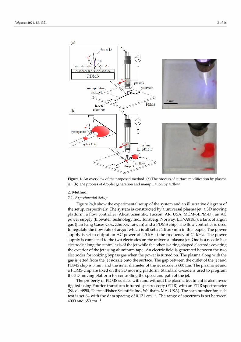
Figure 1 shows an overview of the proposed manipulation method. A universalplasma jet is used for manipulating droplets on a PDMS surface. The key technique of theproposed method is to modify the specified area on the substrate for creating a low surfacetension area, and use the area as patterned paths for droplet manipulation. The jet hastwo modes, which are plasma mode and air-jet mode as shown in Figure 1a,b, respectively.During the plasma mode, the jet works as an APPJ, where the electrodes on the jet createan electric field for ionizing the flow-in argon into its plasma state. The ionized plasma isused for modifying the PDMS surface at the nozzle outlet for reducing the surface tension.Since the size of the jet nozzle is finite, the treatment can be applied to only specifiedareas. As illustrated in Figure 1a, the treated area becomes hydrophilic is due to additionalhydroxyl groups (–OH) binding to the PDMS surface while the untreated area remainshydrophobic. The change of wettability is caused by replacing the methyl groups (–CH3)of PDMS with the silanol groups (Si–O–H) in the plasma-treated area [41,42]. Differentshapes of treated areas can be patterned by the trajectory of the jet moving path, and thewidth of the treatment can be adjusted by the jet speed. A photo of the plasma generatedfrom the jet in the plasma mode is shown on the right of Figure 1a.
Figure 1b shows the universal plasma jet in the air-jet mode. The power applied to theelectrodes on the jet is turned off and results in no electric field for ionizing the argon gas.The argon is flowed through the jet from the inlet to the outlet and create a force field bythe jetted gas. The liquid on the PDMS surface is driven by a drag force from the force fieldfor the droplet manipulation, which includes separating and moving droplets. A snapshotof the universal jet moving a droplet is shown on the right of Figure 1b.
To the best of the authors’ knowledge, this is the first work using a universal plasmajet to generate and manipulate droplets on a PDMS surface. The proposed method aims toprovide a convenient, controllable, and low-cost way to manipulate droplets for studiesin different fields, such as cell culture with droplets encapsulating living cells. Althoughconventional methods often take a long time and require well-trained skill to fabricatea platform for droplet manipulation, the proposed method can directly generate andmanipulate droplets on an untreated PDMS surface using a universal plasma jet. The pro-posed method can simplify droplet manipulation on a polymeric surface towards wall-lessscaffolds for tissue engineering.
The rest of the paper is organized as follows. The working principles, experimentalsetup, and procedures are explained in Section 2. The experimental results on dropletmanipulation and size control are presented in Section 3. The discussions regarding thepotentials and limitations about the proposed method are presented in Section 4. Finally,the concluding remarks are summarized in Section 5.
Polymers 2021, 13, 1321 3 of 16
Figure 1. An overview of the proposed method. (a) The process of surface modification by plasmajet. (b) The process of droplet generation and manipulation by airflow.
2. Method2.1. Experimental Setup
Figure 2a,b show the experimental setup of the system and an illustrative diagram ofthe setup, respectively. The system is constructed by a universal plasma jet, a 3D movingplatform, a flow controller (Alicat Scientific, Tucson, AR, USA, MCM-5LPM-D), an ACpower supply (Biowater Technology Inc., Tonsberg, Norway, LTP-A818F), a tank of argongas (Jian Fang Gases Cor., Zhubei, Taiwan) and a PDMS chip. The flow controller is usedto regulate the flow rate of argon which is all set at 1 litre/min in this paper. The powersupply is set to output an AC power of 4.5 kV at the frequency of 24 kHz. The powersupply is connected to the two electrodes on the universal plasma jet. One is a needle-likeelectrode along the central axis of the jet while the other is a ring-shaped electrode coveringthe exterior of the jet using aluminum tape. An electric field is generated between the twoelectrodes for ionizing bypass gas when the power is turned on. The plasma along with thegas is jetted from the jet nozzle onto the surface. The gap between the outlet of the jet andPDMS chip is 3 mm, and the inner diameter of the jet nozzle is 600 µm. The plasma jet anda PDMS chip are fixed on the 3D moving platform. Standard G-code is used to programthe 3D moving platform for controlling the speed and path of the jet.
The property of PDMS surface with and without the plasma treatment is also inves-tigated using Fourier-transform infrared spectroscopy (FTIR) with an FTIR spectrometer(NicoletiS50, ThermalFisher Scientific Inc., Waltham, MA, USA). The scan number for eachtest is set 64 with the data spacing of 0.121 cm−1. The range of spectrum is set between4000 and 650 cm−1.

Polymers 2021, 13, 1321 4 of 16
Figure 2. The experimental setup. (a) A photo of the experimental setup. (b) A illustrative diagramof the experimental setup.
2.2. PDMS for Manipulation Platform
PDMS is a kind of polymer that is often used for microfluidic chips because of itsbiocompatibility and reproducibility [43]. The droplet manipulation in this work is per-formed using water on a PDMS chip aiming for future cell culture with wall-less scaffolds.PDMS, in general, comprises repeated units of –O–Si (CH3)2. After the plasma treatment,silanol groups Si–O–H substitute for methyl groups –CH3 [42]. Due to the existence of thesilanol groups, the surface becomes hydrophilic, and it can be observed by the change ofthe contact angle [44]. There are many applications of this principle such as PDMS-glassbonding [45], pump-less surfaced microfluidics [46], hydrophilic patterning [47] and etc.
2.3. Drag Force for Droplet Manipulation
The motion of a droplet is driven by jetted air from the universal plasma jet in theair-jet mode. The jetted air pushes the droplet to create an unbalance of forces on thedroplet and result in its motion or deformation. In order to let the droplet move along aspecified path, the surface, where the droplet is, is first modified by the universal plasmajet in the plasma mode, as explained in Section 2.2. The surface with and without plasmamodification would have low surface tension and high surface tension, respectively. Whena droplet is pushed by the jetted air, the droplet would move along the path of low surfacetension because the low surface tension area has less resistance against droplet motion.
Figure 3a shows a droplet sitting on a surface. The contact angles, θA and θB, aredetermined by surface tensions, as the black arrows shown in Figure 3a, on three interfaces,which are the interfaces between any two of liquid, gas, and solid phases. The balance ofthe surface tensions on the three interfaces can be formulated by Young’s law as [48]
(γLG)i cos θi = (γSG)i − (γLS)i i = A or B (1)
where γLG, γLS, γSG and θ are the surface tensions of a droplet on the liquid-gas, liquid-solid, solid-gas interfaces and the contact angle of the droplet, respectively. A and B arethe joint points of the three surface tensions. When the forces on the droplet are balanced,the forces at the points A and B are cancelled each other and the droplet sits still onthe surface.
Figure 3b shows a diagram of the droplet when jetted air is applied to it from theleft. Response of the droplet is determined by all forces exerted on the droplet and theforces include drag force from the jetted air, interfacial forces from surface tension andadhesion, buoyant force and inertial force. Among these forces, drag force, FD, is the mostcritical in the proposed work as it is directly used to move the droplet. To simplify themodeling, the shape of the droplet is approximated as a sphere and the drag force FD canbe formulated as [49–51]
FD = kx
(6π
H2
µUd
)(2)

Polymers 2021, 13, 1321 5 of 16
where kx, H, µ and Ud are the wall correction factor, the effective height of the droplet,the gas viscosity and the nominal flow speed of the gas, respectively. The wall correctionfactor is based on the contact between the droplet and the wall. For example, the wallcorrection factor is 1.7 for a single sphere touching an impermeable wall within simpleshear [52].
Figure 3. Surface tensions and drag force on a droplet. (a) A droplet sits on a surface without jettedair. (b) The droplet is deformed and moved by the drag force FD from the jetted air.
There are two phases of manipulating a droplet when the jetted air is applied on thedroplet. At the beginning, the position of the droplet is held still due to the forces, such asinterfacial and inertial forces, adhering the droplet to the surface. The shape of the droplet isconsequently deformed by the drag force. The deformation gradually increase the dropletheight, H, and decrease the contact area on liquid-solid interface. The drag force on the dropletincreases with the increase of droplet height, according to Equation (2), while the attachingforce to the surface is reduced with the decrease of contact area. Therefore, the drag forceand interfacial force on the droplet would keep increasing and decreasing, respectively.The droplet would be eventually moved by the drag force when the interfacial force is nolonger able to sustain the droplet at the position. In other words, the droplet is moved bythe jetted air when the drag force is greater than all the other forces that prevent the dropletfrom moving, and the motion of the droplet can be programmed with proper control of thedrag force from the jetted air.
2.4. Experimental Procedure2.4.1. Fabrication of PDMS Chip
The PDMS chips are prepared as the platform for droplet manipulation. They arefabricated by mixing PDMS pre-polymer and curing agent (Sylgard 184, Dow CorningInc., Midland, MI, USA) at the weight ratio of 1:10. The mixture is poured into a containerwith flat bottoms for PDMS chips with flat surfaces. The thickness of the poured PDMS iscontrolled at 3 mm. The container of PDMS is put into a vacuum chamber for 30 min toremove the bubbles in the PDMS before putting it into a 90 ◦C oven for 40 min. Finally,the gel-like PDMS is cured as a solid block and is cut for PDMS chips for the platform ofdroplet manipulation in experiments.
2.4.2. Plotting of Droplet Path
The droplet path is first plotted with the universal plasma jet in plasma mode forcreating a path of low surface tension, and the path is used for guiding the direction ofdroplet movement. In order to create a stable and uniform path for the droplets. The uni-versal plasma jet is mounted on the 3D moving platform, as shown in Figure 2. The pathand speed of the jet are controlled by G codes, a standard motion script widely used forpath control. The speeds of 60 mm/min and 300 mm/min are set to the jet for plottingstart reservoir and target reservoir, respectively. The reservoirs here are hydrophilic areas

Polymers 2021, 13, 1321 6 of 16
where the liquid can be stored on the surface of the PDMS chip. The start reservoir is wherethe source of liquid is placed, and the target reservoir is where the generated droplets aresettled for size measurement.
The speed of the jet moving in the region of the droplet path is controlled by the G-codefor creating different widths of the wall-less channels. Different sizes of the droplets areexpected to be generated on the channels. A total of nine different speeds of the jet motionfor plotting different widths of droplet paths are applied in the test, and are, from low tohigh, 750, 822, 900, 1050, 1200, 1350, 1500, 1800 and 2100 mm/min. A lower speed of jetmotion is expected to make a wider channel with a higher degree of hydrophilicity onthe chip since the dose of treatment is greater. In order to quantify the dose of the plasmatreatment, the inverse of the jet speed is used for representing the effective time of plasmatreatment by the following equation.
Te f f =1u
(3)
where Te f f is effective time of plasma treatment, and u is the speed of the plasma jet.The applied speeds of plasma jet can be converted into effective time of plasma treatmentas Te f f = 0.08, 0.073, 0.067, 0.057, 0.05, 0.044, 0.04, 0.033 and 0.029 s/mm, from low speedto high speed, respectively. For the convenience of reading, the effective time of plasmatreatment is shortened as treatment time for the rest of the paper.
2.4.3. Generation and Manipulation of Droplets
Figure 4 shows the steps of droplet generation and manipulation with illustrationsand example photos. For the droplet generation, a bulk-size drop is first placed on theplasma-treated path of the surface. The bulk-size drop in the photos is made of colored waterwith a volume of 10 µL. The universal jet is switch to the air-jet mode with the electric fieldturned off for generating and manipulating droplets from the bulk-size drop. The argon gasis jetted from the outlet of the jet and generates a force field. When the jet is right abovethe bulk drop, the force field pushes the surface of the bulk drop against the PDMS surfaceand creates a circular area as shown in the central-upper photo of Figure 4. With the jet ismoving away from the center of the bulk drop, the circular area moves with the jet and atcertain points, the jetted gas would separate a small droplet from the bulk drop.
Figure 4. Mechanism of the droplet generation and manipulation with sampled photos from experi-ments. (a) The process of the droplet generation from a source drop. (b) The process of the dropletmanipulation with jetted air.
For the droplet manipulation, a drag force from the force field generated by the jettedair is used on the separated droplet, as explained in Section 2.3. The droplet is pushing
Polymers 2021, 13, 1321 7 of 16
away from the jetted air. Due to the plasma treatment, the moving direction of the dropletis not random but follows the plasma-treated path by the plasma jet with plasma mode.The speed and direction of the droplet movement is controlled by the jetted air during thedroplet manipulation. According to Equation (2), the selection of gas and different flowspeed would result in different drag force and different droplet movement.
2.5. Measurement of Droplet Size
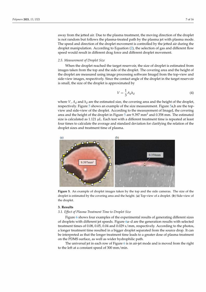
When the droplet reached the target reservoir, the size of droplet is estimated fromimages taken from the top and the side of the droplet. The covering area and the height ofthe droplet are measured using image processing software ImageJ from the top-view andside-view images, respectively. Since the contact angle of the droplet in the target reservoiris small, the size of the droplet is approximated by
V =13
Adhd (4)
where V, Ad and hd are the estimated size, the covering area and the height of the droplet,respectively. Figure 5 shows an example of the size measurement. Figure 5a,b are the top-view and side-view of the droplet. According to the measurement of ImageJ, the coveringarea and the height of the droplet in Figure 5 are 9.397 mm2 and 0.358 mm. The estimatedsize is calculated as 1.121 µL. Each test with a different treatment time is repeated at leastfour times to calculate the average and standard deviation for clarifying the relation of thedroplet sizes and treatment time of plasma.
Figure 5. An example of droplet images taken by the top and the side cameras. The size of thedroplet is estimated by the covering area and the height. (a) Top-view of a droplet. (b) Side-view ofthe droplet.
3. Results3.1. Effect of Plasma Treatment Time to Droplet Size
Figure 6 shows four examples of the experimental results of generating different sizesof droplets with different jet speeds. Figure 6a–d are the generation results with selectedtreatment times of 0.08, 0.05, 0.04 and 0.029 s/mm, respectively. According to the photos,a longer treatment time resulted in a bigger droplet separated from the source drop. It canbe interpreted as that the longer treatment time leads to a greater dose of plasma treatmenton the PDMS surface, as well as wider hydrophilic path.
The universal jet in each row of Figure 6 is in air-jet mode and is moved from the rightto the left at a constant speed of 300 mm/min.

Polymers 2021, 13, 1321 8 of 16
Figure 6. Examples of different size droplets generated and manipulated by different treatment timesof plasma. The treatment times are (a) 0.08 s/mm. (b) 0.05 s/mm. (c) 0.04 s/mm. (d) 0.029 s/mm.
The initial volume of the bulk-size drop on the right of the PDMS chip is 10 µL. In thecase of the longest treatment time of 0.08 s/mm shown in Figure 6a, a big portion from thebulk drop is pushed to the left as the jet moving to the left. When the separated drop reachedto the target area and settled, as the “goal” labeled in the rightmost photo of Figure 6a, the sizeof the separated drop is measured based on top-view and side-view cameras. The sizeof the pushed-out droplet is getting smaller with the decrease of treatment time, and thesmallest droplet is generated with the shortest treatment time of 0.029 s/mm, as shown inFigure 6d. The treatment time is about 3 times shorter while the droplet size is more than40 times smaller.
Figure 7 shows the results of all 9 different treatment times and their resulting sizes ofdroplets during the generation test. Each measurement is repeated at least four times for the9 different treatment times. The data points and the length of the error bars represent theaverage and standard deviation of the measured results. A trend of droplet size increasingwith the increase of treatment time can be observed. The largest and the smallest sizesof the manipulated droplets are around 6 µL and 0.1 µL, respectively. An exponentialfunction is fit with the points of average values and the correlation coefficient R is 0.9083.It shows that the size of the droplet can be controlled by different jet moving speeds, i.e.,a smaller size droplet can be generated with a faster-moving speed and vice versa. On theother hand, the standard deviations are found increasing with the increase of the treatment

Polymers 2021, 13, 1321 9 of 16
time, and it indicates that the generation of droplet size requires additional control ofmanipulation conditions for big droplets.
Figure 7. The relation of droplet sizes and treatment time of plasma.
3.2. Droplet Mixing with Controllable Droplet
Figure 8 shows the application of the proposed method for performing a mixing taskon a PDMS chip. Figure 8a shows the design of the mixing chip and snapshots of the mixingprocess during the test. Two different liquids of the same volume of 10 µL are first placed ontwo sides of the chip, as the blue and red-colored water shown in Figure 8a. The blue andred-colored water are labeled as buffer liquid and testing liquid in Figure 8a, respectively.The dashed lines in the top diagram of Figure 8a indicate the path of plasma treatment.The center of the chip is where the two liquids are mixed. The snapshots in Figure 8ademonstrate how the two liquids are moved together for the mixing. The red-colored liquidis first moved to the center and is followed by moving blue-colored liquid to the center.The operation is designed as a concentration control in droplet-based applications [53].
Figure 8. Mixing test. (a) The mixing system and the processes of the mixing test. (b) Comparison ofexperimental values and expected values in the mixing test.
Figure 8b shows the results from the mixing test. For controlling the concentrationof the final mixed liquid, five different treatment times of plasma from the side of buffer

Polymers 2021, 13, 1321 10 of 16
liquid, the blue one, to the center are applied. The treatment times for the path to thebuffer liquid includes 0.040 s/mm, 0.044 s/mm, 0.050 s/mm, 0.057 s/mm and 0.067 s/mm.On the other hand, the treatment time for the path to the testing liquid, the red one, isfixed at 0.050 s/mm. The mixing test with each treatment time is repeated four times.The experimental value of the concentration is determined based on the volume ratio ofthe droplets from two sides, i.e., when a droplet is separated from the source drop, the sizeand height are visually measured before it reached the center chamber. The expectedvalues are predicted from the relation of droplet size and treatment time of plasma fromprevious results in Figure 7. According to the comparison in Figure 8b, the differencesbetween experimental values and expected values are 3%, 3%, 4%, 2% and 1% for thetreatment times of 0.04, 0.044, 0.05, 0.057 and 0.067 s/mm, respectively. It demonstrates therepeatability and feasibility of the method for mixing applications.
3.3. FTIR Spectrum on PDMS Surface
The treatment of argon plasma on the PDMS surface is investigated using a FTIRspectrometer, and the results are shown in Figure 9. The red and black data in Figure 9represent the obtained spectra of the PDMS surfaces with and without plasma treatment,respectively. For the convenience of reading, potential functional groups, such as OH andCH3, are labeled in Figure 9 according to the infrared spectrum table (IR Spectrum Tableby Frequency Range, Merck KGaA, Darmstadt, Germany). FTIR Scanning is performed64 times during a single measurement to enhance the scanning results. The results showthat the spectra of PDMS surface with and without plasma treatment are mostly overlappedwith each other. A weak broad peak is found around the wavenumber between 3000 cm−1
and 3700 cm−1 in the spectrum of the PDMS with plasma treatment. The peak indicatesthe formation of hydroxyl groups on the PDMS surface upon the plasma treatment, and iswell matched to previous results on plasma treatment of PDMS surfaces [54–56]. Theresults show that the plasma treatment with the proposed universal jet enhanced thehydrophilicity of the PDMS surface, and the jet in its plasma mode can be used for plottingpaths for the droplet manipulation.
Figure 9. The spectra of PDMS surface with and without plasma treatment is measured with a FTIRspectrometer. A weak broad peak is observed in the range of 3000 and 3700 cm−1.
4. Discussion4.1. Aging of Plasma-Treated Surface in Atmosphere
The sustainability and aging on plasma-treated surface is critical to the proposedmethod and is discussed here. It is known that th hydroxyl groups on the treated surfaceare not permanent and the surface would return to hydrophobic condition in an openspace [57,58]. Figure 10a shows sample photos of the measurement of contact angles withthree different treatment time of plasma. The treatment time, from the left to the right, are

Polymers 2021, 13, 1321 11 of 16
of 0.08, 0.05 and 0.029 s while the aging time, from the top to the bottom, are 0, 60 and120 min, respectively.
Figure 10. Aging effect of plasma treatment. (a) The measurement of contact angle of treatment timeof plasma of 0.08, 0.05 and 0.029 s at aging time of 0, 60 and 120 min. (b) Aging effect of differenttreatment time of plasma. (c) The relation of contact angle and droplet size.
At the moment of 0 min, the contact angles are 38.71◦, 53.66◦ and 69.96◦, and it showsthat the longer treatment time would result in a smaller contact angle. The contact anglesafter 60 min are shown in the second row in Figure 10a. the contact angles increase to 62.18◦,66.77◦ and 76.26◦, from the left to the right, respectively. After two hours, the contact anglesincrease to 72.01◦, 76.28◦ and 81.57◦.
Figure 10b shows the aging effect of different treatment time of plasma. It showsthe trends that the contact angles on the plotted channels become larger with theincreased aging time. All the treated surfaces nearly recover to 80◦ after 120 min agingtime. Figure 10c shows the relation of contact angles and manipulated droplet sizes.Combination of Figure 10b,c, it can be observed that manipulated droplet size becomessmaller with the increased aging time. Therefore, the timing of droplet manipulation withthe proposed method is important for repeatability and reliability.
4.2. Aging of Plasma-Treated Surface during Droplet Manipulation
The aging effect of the plasma-treated surface is also tested during the droplet manip-ulation. The aging is expected to be much faster during the droplet manipulation becausehydroxyl groups could be easily taken away by the droplet, and particularly, water isused for the droplet in the test. Figure 11 shows the results of droplet size with respectto manipulation time when the effective time of plasma treatment is set to 0.067 s/mm.One time of manipulation means moving a droplet from the liquid reservoir to the targetchamber. The time between every two manipulation is kept about one minutes and the

Polymers 2021, 13, 1321 12 of 16
liquid reservoir is filled up with 10 µL for the consistency during the test. The marksand error bars in Figure 11 represents the averages and standard deviations of test over3 times. The results show that the droplet size becomes about half after 5 times of dropletmanipulation, which is approximately 4 min after the first manipulation. The photos showthe droplet size after the manipulations.
Figure 11. Droplet size is found decreased with the increase number of manipulations on the sameplasma-treated path.
The size of the droplet may also depend on the size of the bulk drop in the liquidreservoir and is tested with repeating generations of droplets from the same bulk drop.Figure 12 shows the experimental results of the test. Figure 12a–c are the sample imagestaken during the processes of manipulation times N of 1, 4, and 9, respectively. The dropletsize decreases with the increased number of generations. When the numbers of dropletgeneration achieved 9, no droplet can be generated from the drop. This could be combinedeffect of aging of plasma treatment and size of bulk drop.
Figure 12. Repeated droplet generation with different plasma treatment. (a) A photo of the firstdroplet. (b) A photo of the fourth droplet. (c) No droplet is generated after nine times of generation.(d) The relation of the droplet size and times of generation at different treatment time of plasma.

Polymers 2021, 13, 1321 13 of 16
Figure 12d summarize the same repeating generation of droplets with different treat-ment times of plasma. A similar trend of the droplet size that the size decreases with theincreasing number of droplet generation has been observed among different treatmenttimes of plasma.
4.3. The Comparison and Limitations
A table of comparison among different technologies that manipulate droplet areshown in Table 1. Although EWOD and magnetic system are fairly matured for dropletmanipulation, the proposed method has great potential that it only needs a few seconds tobuild up a manipulation platform, which is especially convenient for disposable chips fordigital microfluidics. simplicity and easy maintenance are also the advantages of usingsuch a multipurpose plasma jet in a manipulation system. In addition, the plasma jetcan apply plasma-generated functional groups to droplets by turning on the electric fieldon the jet while handling the droplets with the jet. It may provide a useful assist to celladhesion and cultivation in potential applications. For example, the sterilization functionof low-temperature plasma could be a useful assist for handling droplets encapsulatingliving cells.
Aging, roughness, and differences in surface tension can affect the performance ofthe manipulation system and are challenges and limitations for the proposed method.Further investigations on these issues are needed for improving the proposed method,or to develop new features based on these limitations. For example, there is a potentialfor employing the aging effect for re-writable paths of droplets on a PDMS surface for amultifunction platform.
Table 1. Comparison of droplet manipulating technologies.
Universal Plasma Jet(Proposed)
Electrowetting onDielectric(EWOD)
Magnetic-ControlledDroplet
mechanism surface treatment andhydrodynamic force
electrical wetting andpressure gradient
magnetic force onparticles or fluid
droplet size submicrolitre tomicroliters
picolitre totens of microliters
submicrolitre totens of microliters
fabricationtime
of platform
few seconds forpath plotting
several days formultilayer structure
minutes/hours forsurface coating and
magnets arrangement
cost lowair or selected gas
highmultilayer and
electrodesfabrication
mediummagnetic beads/fluid
featurescan directly apply onpolymeric substratefunctional radicals
accurate controlno need pumps/valvesno need fluid pathways
particles can be usedas functional substrate
can be manuallyoperated
Ref This work Nelson and Kim 2012 [59] Zhang and Nguyen [60]
5. Conclusions
A novel method for manipulating droplet on a PDMS surface with a universal plasmajet is proposed and tested in this work. The droplets can be generated and manipulatedby the plasma mode and air-jet mode of the universal plasma jet. The main concludingremarks are listed as follows.
• The size of droplet can be controlled by the treatment time of plasma using theuniversal plasma jet. The relation of droplet size and treatment time of plasma hasbeen experimentally clarified. It shows that shorter treatment time of plasma results insmaller size of manipulated droplet. The largest and the smallest sizes of manipulated

Polymers 2021, 13, 1321 14 of 16
droplet are around 6 µL and 0.1 µL, which are achieved by the treatment time of0.08 s/mm and 0.029 s/mm, respectively.
• An application of mixing two colored liquids has been successfully performed. The dif-ference between the expected concentration and actual concentration are all below 5%,which demonstrates the feasibility of applying the proposed method in an application.
• The aging of the plasma-treated path in both atmosphere and during manipulationhave been investigated. The contact angles of channel become larger with the increasedaging time and nearly recovers to 80◦ after 120 min aging time in every tests oftreatment time of plasma. The aging is even faster during the manipulation due to thedirect contact with droplets.
Author Contributions: Conceptualization, C.-Y.P. and C.-H.D.T.; methodology, C.-Y.P. and C.-H.D.T.;validation, C.-Y.P. and C.-H.D.T.; resources, C.-H.D.T.; writing—original draft preparation, C.-Y.P.;writing—review and editing, C.-H.D.T.; visualization, C.-Y.P. and C.-H.D.T.; supervision, C.-H.D.T.; fund-ing acquisition, C.-H.D.T. All authors have read and agreed to the published version of the manuscript.
Funding: This research was funded by Taiwan Ministry of Science and Technology (MOST) grantnumber 109-2221-E-009-035- and 108-2221-E-009-107.
Institutional Review Board Statement: Not applicable.
Informed Consent Statement: Not applicable.
Data Availability Statement: Data are available upon reasonable request.
Acknowledgments: The authors would like to thank Jong-Shinn Wu for his technical advice onplasma science and technology. The authors would also like to thank Jin-Jia Hu for supporting theFTIR measurement and his advice on interpreting the FTIR results.
Conflicts of Interest: The authors declare no conflict of interest.
AbbreviationsThe following abbreviations are used in this manuscript:
APPJ Atmospheric-Pressure Plasma JetPDMS Polydimethylsiloxane
References1. Shin, D.J.; Wang, T.H. Magnetic droplet manipulation platforms for nucleic acid detection at the point of care. Ann. Biomed. Eng.
2014, 42, 2289–2302. [CrossRef]2. Malic, L.; Brassard, D.; Veres, T.; Tabrizian, M. Integration and detection of biochemical assays in digital microfluidic LOC devices.
Lab A Chip 2010, 10, 418–431. [CrossRef]3. Shikida, M.; Takayanagi, K.; Inouchi, K.; Honda, H.; Sato, K. Using wettability and interfacial tension to handle droplets of
magnetic beads in a micro-chemical-analysis system. Sens. Actuators B Chem. 2006, 113, 563–569. [CrossRef]4. Wang, Y.B.; Huang, J.H.; Lee, M.S.; Huang, C.Y.; Huang, C.S.; Yamashita, I.; Tu, Y.Y.; Hsu, W. An EWOD-based micro diluter with
high flexibility on dilution ratio. Microsyst. Technol. 2017, 23, 3645–3651. [CrossRef]5. Moon, H.; Cho, S.K.; Garrell, R.L.; Kim, C.J. Low voltage electrowetting-on-dielectric. J. Appl. Phys. 2002, 92, 4080–4087.
[CrossRef]6. Zhang, Y.; Wang, T.H. Full-range magnetic manipulation of droplets via surface energy traps enables complex bioassays.
Adv. Mater. 2013, 25, 2903–2908. [CrossRef] [PubMed]7. Long, Z.; Shetty, A.M.; Solomon, M.J.; Larson, R.G. Fundamentals of magnet-actuated droplet manipulation on an open
hydrophobic surface. Lab A Chip 2009, 9, 1567–1575. [CrossRef] [PubMed]8. Huang, G.; Li, M.; Yang, Q.; Li, Y.; Liu, H.; Yang, H.; Xu, F. Magnetically actuated droplet manipulation and its potential
biomedical applications. ACS Appl. Mater. Interfaces 2017, 9, 1155–1166. [CrossRef]9. Wang, Z.; Zhe, J. Recent advances in particle and droplet manipulation for lab-on-a-chip devices based on surface acoustic waves.
Lab A Chip 2011, 11, 1280–1285. [CrossRef] [PubMed]10. Sesen, M.; Alan, T.; Neild, A. Microfluidic on-demand droplet merging using surface acoustic waves. Lab A Chip 2014,
14, 3325–3333. [CrossRef] [PubMed]11. Park, S.Y.; Kalim, S.; Callahan, C.; Teitell, M.A.; Chiou, E.P. A light-induced dielectrophoretic droplet manipulation platform.
Lab A Chip 2009, 9, 3228–3235. [CrossRef] [PubMed]

Polymers 2021, 13, 1321 15 of 16
12. Ahn, K.; Kerbage, C.; Hunt, T.P.; Westervelt, R.; Link, D.R.; Weitz, D.A. Dielectrophoretic manipulation of drops for high-speedmicrofluidic sorting devices. Appl. Phys. Lett. 2006, 88, 024104. [CrossRef]
13. Park, S.Y.; Teitell, M.A.; Chiou, E.P. Single-sided continuous optoelectrowetting (SCOEW) for droplet manipulation with lightpatterns. Lab A Chip 2010, 10, 1655–1661. [CrossRef] [PubMed]
14. Jiang, D.; Park, S.Y. Light-driven 3D droplet manipulation on flexible optoelectrowetting devices fabricated by a simplespin-coating method. Lab A Chip 2016, 16, 1831–1839. [CrossRef] [PubMed]
15. Zhang, S.; Li, G.; Man, J.; Zhang, S.; Li, J.; Li, J.; Li, D. Fabrication of Microspheres from High-Viscosity Bioink Using a NovelMicrofluidic-Based 3D Bioprinting Nozzle. Micromachines 2020, 11, 681. [CrossRef] [PubMed]
16. Du, G.S.; Pan, J.Z.; Zhao, S.P.; Zhu, Y.; den Toonder, J.M.; Fang, Q. Cell-based drug combination screening with a microfluidicdroplet array system. Anal. Chem. 2013, 85, 6740–6747. [CrossRef]
17. Hutmacher, D.W. Scaffold design and fabrication technologies for engineering tissues—State of the art and future perspectives.J. Biomater. Sci. Polym. Ed. 2001, 12, 107–124. [CrossRef]
18. Chen, Q.; Utech, S.; Chen, D.; Prodanovic, R.; Lin, J.M.; Weitz, D.A. Controlled assembly of heterotypic cells in a core–shellscaffold: organ in a droplet. Lab A Chip 2016, 16, 1346–1349. [CrossRef] [PubMed]
19. Um, E.; Lee, D.S.; Pyo, H.B.; Park, J.K. Continuous generation of hydrogel beads and encapsulation of biological materials usinga microfluidic droplet-merging channel. Microfluid. Nanofluid. 2008, 5, 541–549. [CrossRef]
20. Li, C.Y.; Hu, M.H.; Hu, J.J. Use of aligned microscale sacrificial fibers in creating biomimetic, anisotropic poly (glycerol sebacate)scaffolds. Polymers 2019, 11, 1492. [CrossRef]
21. Wu, S.T.; Huang, C.Y.; Weng, C.C.; Chang, C.C.; Li, B.R.; Hsu, C.S. Rapid Prototyping of an Open-Surface Microfluidic PlatformUsing Wettability-Patterned Surfaces Prepared by an Atmospheric-Pressure Plasma Jet. ACS Omega 2019, 4, 16292–16299.[CrossRef] [PubMed]
22. Morrissette, J.M.; Mahapatra, P.S.; Ghosh, A.; Ganguly, R.; Megaridis, C.M. Rapid, self-driven liquid mixing on open-surfacemicrofluidic platforms. Sci. Rep. 2017, 7, 1–13. [CrossRef] [PubMed]
23. Nguyen, P.Q.; Yeo, L.P.; Lok, B.K.; Lam, Y.C. Patterned surface with controllable wettability for inkjet printing of flexible printedelectronics. ACS Appl. Mater. Interfaces 2014, 6, 4011–4016. [CrossRef] [PubMed]
24. Wu, Y.; Kouno, M.; Saito, N.; Nae, F.A.; Inoue, Y.; Takai, O. Patterned hydrophobic—Hydrophilic templates made frommicrowave-plasma enhanced chemical vapor deposited thin films. Thin Solid Films 2007, 515, 4203–4208. [CrossRef]
25. Huang, C.; Wu, S.Y.; Chang, Y.C. Synthesis of organosilicon film on polycarbonate by means of low-temperature atmospheric-pressure plasma jet. IEEE Trans. Plasma Sci. 2010, 38, 1101–1105. [CrossRef]
26. Shaw, D.; West, A.; Bredin, J.; Wagenaars, E. Mechanisms behind surface modification of polypropylene film using an atmospheric-pressure plasma jet. Plasma Sources Sci. Technol. 2016, 25, 065018. [CrossRef]
27. Lai, J.; Sunderland, B.; Xue, J.; Yan, S.; Zhao, W.; Folkard, M.; Michael, B.D.; Wang, Y. Study on hydrophilicity of polymer surfacesimproved by plasma treatment. Appl. Surf. Sci. 2006, 252, 3375–3379. [CrossRef]
28. Shao, T.; Zhou, Y.; Zhang, C.; Yang, W.; Niu, Z.; Ren, C. Surface modification of polymethyl-methacrylate using atmosphericpressure argon plasma jets to improve surface flashover performance in vacuum. IEEE Trans. Dielectr. Electr. Insul. 2015,22, 1747–1754. [CrossRef]
29. Bagiatis, V.; Critchlow, G.; Price, D.; Wang, S. The effect of atmospheric pressure plasma treatment (APPT) on the adhesive bondingof poly (methyl methacrylate)(PMMA)-to-glass using a polydimethylsiloxane (PDMS)-based adhesive. Int. J. Adhes. Adhes. 2019,95, 102405. [CrossRef]
30. Dey, A.; Lopez, A.; Filipic, G.; Jayan, A.; Nordlund, D.; Koehne, J.; Krishnamurthy, S.; Gandhiraman, R.P.; Meyyappan, M. Plasmajet based in situ reduction of copper oxide in direct write printing. J. Vac. Sci. Technol. B Nanotechnol. Microelectron. Mater. Process.Meas. Phenom. 2019, 37, 031203. [CrossRef]
31. Fang, J.; Levchenko, I.; Mai-Prochnow, A.; Keidar, M.; Cvelbar, U.; Filipic, G.; Han, Z.J.; Ostrikov, K.K. Protein retention onplasma-treated hierarchical nanoscale gold-silver platform. Sci. Rep. 2015, 5, 1–11. [CrossRef]
32. Kim, M.; Song, D.; Shin, H.; Baeg, S.H.; Kim, G.; Boo, J.H.; Han, J.; Yang, S. Surface modification for hydrophilic property ofstainless steel treated by atmospheric-pressure plasma jet. Surf. Coat. Technol. 2003, 171, 312–316. [CrossRef]
33. Thomas, M.; Herrmann, A.; Dohse, A.; Borris, J.; Weidlich, E.R. Printing of µm structures with nano inks using a novelcombination of high-resolution plasma printing and subsequent rotogravure printing. Plasma Process. Polym. 2019, 16, 1900080.[CrossRef]
34. Liu, J.; Song, J.; Wang, G.; Chen, F.; Liu, S.; Yang, X.; Sun, J.; Zheng, H.; Huang, L.; Jin, Z.; et al. Maskless hydrophilic patterning ofthe superhydrophobic aluminum surface by an atmospheric pressure microplasma jet for water adhesion controlling. ACS Appl.Mater. Interfaces 2018, 10, 7497–7503. [CrossRef] [PubMed]
35. Wu, M.C.; Liao, C.W.; Lin, Z.H.; Yang, C.M.; Cheng, Y.P.; Wu, J.S. Experimental investigation of sterilization efficacy of greennails symptom and gray nails using an argon-based round atmospheric-pressure plasma jet. Biomed. Phys. Eng. Express 2019,5, 025034. [CrossRef]
36. Cheng, K.Y.; Lin, Z.H.; Cheng, Y.P.; Chiu, H.Y.; Yeh, N.L.; Wu, T.K.; Wu, J.S. Wound healing in streptozotocin-induced diabeticrats using atmospheric-pressure argon plasma jet. Sci. Rep. 2018, 8, 1–15.

Polymers 2021, 13, 1321 16 of 16
37. Patelli, A.; Mussano, F.; Brun, P.; Genova, T.; Ambrosi, E.; Michieli, N.; Mattei, G.; Scopece, P.; Moroni, L. Nanoroughness,surface chemistry, and drug delivery control by atmospheric plasma jet on implantable devices. ACS Appl. Mater. Interfaces 2018,10, 39512–39523. [CrossRef]
38. Lin, Z.H.; Tschang, C.Y.T.; Liao, K.C.; Su, C.F.; Wu, J.S.; Ho, M.T. Ar/O2 argon-based round atmospheric-pressure plasma jet onsterilizing bacteria and endospores. IEEE Trans. Plasma Sci. 2016, 44, 3140–3147. [CrossRef]
39. Yu, Y.S.; Wu, M.C.; Wu, J.S.; Tsai, C.H.D. Rapid Prototyping of Microfluidic Channel using Atmospheric Pressure Plasma Jet. InProceedings of the 22nd International Conference on Miniaturized Systems for Chemistry and Life Sciences, MicroTAS 2018,Kaohsiung, Taiwan, 11–15 November 2018; pp. 551–554.
40. Yu, Y.S.; Kuo, L.H.; Wu, M.C.; Wu, J.S.; Tsai, C.H.D. A Novel Fabrication of PDMS Chip using Atmospheric Pressure Plasma Jet:Hydrophobicity Modification and Feasibility Test. In Proceedings of the 2018 IEEE/RSJ International Conference on IntelligentRobots and Systems (IROS), Madrid, Spain, 1–5 October 2018; pp. 278–283.
41. Owen, M.J.; Smith, P.J. Plasma treatment of polydimethylsiloxane. J. Adhes. Sci. Technol. 1994, 8, 1063–1075. [CrossRef]42. Ng, J.M.; Gitlin, I.; Stroock, A.D.; Whitesides, G.M. Components for integrated poly (dimethylsiloxane) microfluidic systems.
Electrophoresis 2002, 23, 3461–3473. [CrossRef]43. Berthier, E.; Young, E.W.; Beebe, D. Engineers are from PDMS-land, Biologists are from Polystyrenia. Lab A Chip 2012,
12, 1224–1237. [CrossRef]44. Kim, K.; Kim, G.; Oh, Y.; Park, T.G.; Han, D.C.; Yang, S.S. Simple atmospheric-pressure nonthermal plasma-jet system for poly
(dimethylsiloxane) bonding process. Jpn. J. Appl. Phys. 2012, 51, 06FL15. [CrossRef]45. Bhattacharya, S.; Datta, A.; Berg, J.M.; Gangopadhyay, S. Studies on surface wettability of poly (dimethyl) siloxane (PDMS) and
glass under oxygen-plasma treatment and correlation with bond strength. J. Microelectromech. Syst. 2005, 14, 590–597. [CrossRef]46. Oliveira, N.M.; Neto, A.I.; Song, W.; Mano, J.F. Two-dimensional open microfluidic devices by tuning the wettability on patterned
superhydrophobic polymeric surface. Appl. Phys. Express 2010, 3, 085205. [CrossRef]47. Huang, S.; Song, J.; Lu, Y.; Chen, F.; Zheng, H.; Yang, X.; Liu, X.; Sun, J.; Carmalt, C.J.; Parkin, I.P.; et al. Underwater
spontaneous pumpless transportation of nonpolar organic liquids on extreme wettability patterns. ACS Appl. Mater. Interfaces2016, 8, 2942–2949. [CrossRef]
48. Eid, K.; Panth, M.; Sommers, A. The physics of water droplets on surfaces: Exploring the effects of roughness and surfacechemistry. Eur. J. Phys. 2018, 39, 025804. [CrossRef]
49. Peng, S.; Williams, R.A. Controlled production of emulsions using a crossflow membrane: Part I: Droplet formation from a singlepore. Chem. Eng. Res. Des. 1998, 76, 894–901. [CrossRef]
50. Fan, J.; Wilson, M.; Kapur, N. Displacement of liquid droplets on a surface by a shearing air flow. J. Colloid Interface Sci. 2011,356, 286–292. [CrossRef] [PubMed]
51. Subramanian, R.S.; Moumen, N.; McLaughlin, J.B. Motion of a drop on a solid surface due to a wettability gradient. Langmuir2005, 21, 11844–11849. [CrossRef] [PubMed]
52. O’Neill, M.E. A slow motion of viscous liquid caused by a slowly moving solid sphere. Mathematika 1964, 11, 67–74. [CrossRef]53. Lee, M.S.; Hsu, W.; Huang, H.Y.; Tseng, H.Y.; Lee, C.T.; Hsu, C.Y.; Shieh, Y.C.; Wang, S.H.; Yao, D.J.; Liu, C.H. Simultane-
ous detection of two growth factors from human single-embryo culture medium by a bead-based digital microfluidic chip.Biosens. Bioelectron. 2020, 150, 111851. [CrossRef]
54. Kim, H.T.; Jeong, O.C. PDMS surface modification using atmospheric pressure plasma. Microelectron. Eng. 2011, 88, 2281–2285.[CrossRef]
55. Hui, A.Y.; Wang, G.; Lin, B.; Chan, W.T. Microwave plasma treatment of polymer surface for irreversible sealing of microfluidicdevices. Lab A Chip 2005, 5, 1173–1177. [CrossRef]
56. Hillborg, H.; Gedde, U. Hydrophobicity recovery of polydimethylsiloxane after exposure to corona discharges. Polymer 1998,39, 1991–1998. [CrossRef]
57. Bodas, D.; Khan-Malek, C. Hydrophilization and hydrophobic recovery of PDMS by oxygen plasma and chemical treatment—AnSEM investigation. Sens. Actuators B Chem. 2007, 123, 368–373. [CrossRef]
58. Murakami, T.; Kuroda, S.I.; Osawa, Z. Dynamics of polymeric solid surfaces treated with oxygen plasma: Effect of aging mediaafter plasma treatment. J. Colloid Interface Sci. 1998, 202, 37–44. [CrossRef]
59. Nelson, W.C.; Kim, C.J. Droplet actuation by electrowetting-on-dielectric (EWOD): A review. J. Adhes. Sci. Technol. 2012,26, 1747–1771. [CrossRef]
60. Zhang, Y.; Nguyen, N.T. Magnetic digital microfluidics—A review. Lab A Chip 2017, 17, 994–1008. [CrossRef]
Copyright © 2022 FDOKUMEN