Rheology of an artificial smectitic clay
7
Rheology of an artificial smectitic clay Roland Pusch a, ⁎, Lie Zhang b , Robert Adey b , Jörn Kasbohm c a Geodevelopment Int. AB, Lund, Sweden, Southampton, UK b C M BEASY Ltd, Southampton, UK c Greifswald University, Greifswald, Germany abstract article info Article history: Received 7 January 2008 Received in revised form 25 August 2009 Accepted 27 August 2009 Available online 8 September 2009 Keywords: Activation energy Clay Creep Shearing Smectite The extremely long time in which clay surrounding canisters with radioactive waste must serve makes it necessary to consider long-term strain. It may have a sufficient shear strength for providing short-term stability but accumulated creep strain may well lead to failure if the microstructural coherence is lost. This can happen to non-expanding clays in which the number of “slip” units is more or less constant or reduced by bulk strain. For smectites, the risk of creep failure is believed to be insignificant because shearing of the originally dense clay aggregates break them up and produces an increasing number of slip units. This microstructural performance is described by a creep model based on stochastical mechanics, implying a spectrum of interparticle bond strengths that represent a first-order variation in barrier heights, and a second represented by the interaction of differently sized aggregates of discrete particles and a transient increase in the frequency of slip units. Low shear stresses cause strong attenuation of the creep rate, while for intermediate stresses the creep rate is of log time type. High shear stresses yield an increasing number of slip units that makes the clay perform as a purely viscous medium. Experiments made by the use of a new ring shear device support the theoretical creep model. © 2009 Elsevier B.V. All rights reserved. 1. Cases While natural clays perform according to conventional Terzaghian soil mechanics, artificially prepared ones appear to behave differently, which is of importance in the following practical cases shown in Fig. 1: 1. heavy canister with highly active radioactive waste, like spent fuel, resting on smectite-rich “buffer” clay (left in Fig. 1), 2. slope in pile of granular smectitic clay (upper right in Fig. 1), and 3. shallow liner of granular smectitic clay (lower right in Fig. 1). The most simple case is the liner. It represents 2D conditions and corresponds to the case of an infinitely long slope containing a clay layer that can become unstable by slipping along its lower boundary. The required shear strength is τ f =ρH(n/1+n 2 ) where ρ is the density of the clay, H the vertical thickness of the clay layer, and 1/n the inclination. For β =17 o (n = 0.3), H = 1 m and ρ = 2000 kg/m 3 , slip takes place for a shear strength of 6 kPa. Adding the load of overlying draining layers and applying a reasonable safety factor the required shear strength may be more than three times higher. This may well be achievable but the real problem is the risk of long-term creep leading to large strain and ultimate failure. The sloping fill will fail by sliding along a macroscopic slip surface that is initiated in the part of the clay mass where the shear stresses are highest (fine-dotted rectangle in Fig. 1). Critical conditions are first reached in the most highly stressed clay element and when adjacent elements reach this conditions by creep strain an unstable zone develops that grows by extended creep and ultimately forms a more or less cylindrical, macroscopic slip surface. The most complex case is the heavy canister resting in smectitic clay. Assuming that the clay is confined by the surrounding rock and that the canister is instantaneously placed in the clay it will cause consolidation of the clay, i.e. expulsion of porewater by compression to reach complete dissipation of the generated excess water pressure. The shear stresses in the elements generate creep strain under constant volume conditions that lead to settlement of the canister and to the flow of the clay mass upwards and around it. If the load is sufficiently high the canister can sink down and reach the bottom of the hole. We will focus on the canister case in this paper, with special respect to the settlement taking place in a long-term perspective. It cannot be accepted to exceed a few tens of millimetres. 2. Creep modelling 2.1. Clay microstructure The microstructural network of smectite clay can be generalized as in Fig. 2. Each little line repesents a stack of lamellae, most of them with a length of 0.01 to 0.5 μm and a thickness of 3–10 nm. They Applied Clay Science 47 (2010) 120–126 ⁎ Corresponding author. E-mail addresses: [email protected] (R. Pusch), [email protected] (R. Adey). 0169-1317/$ – see front matter © 2009 Elsevier B.V. All rights reserved. doi:10.1016/j.clay.2009.08.031 Contents lists available at ScienceDirect Applied Clay Science journal homepage: www.elsevier.com/locate/clay
-
Upload
independent -
Category
Documents
-
view
1 -
download
0
Transcript of Rheology of an artificial smectitic clay
Applied Clay Science 47 (2010) 120–126
Contents lists available at ScienceDirect
Applied Clay Science
j ourna l homepage: www.e lsev ie r.com/ locate /c lay
Rheology of an artificial smectitic clay
Roland Pusch a,⁎, Lie Zhang b, Robert Adey b, Jörn Kasbohm c
a Geodevelopment Int. AB, Lund, Sweden, Southampton, UKb C M BEASY Ltd, Southampton, UKc Greifswald University, Greifswald, Germany
⁎ Corresponding author.E-mail addresses: [email protected]
(R. Adey).
0169-1317/$ – see front matter © 2009 Elsevier B.V. Adoi:10.1016/j.clay.2009.08.031
a b s t r a c t
a r t i c l e i n f oArticle history:Received 7 January 2008Received in revised form 25 August 2009Accepted 27 August 2009Available online 8 September 2009
Keywords:Activation energyClayCreepShearingSmectite
The extremely long time in which clay surrounding canisters with radioactive waste must serve makes itnecessary to consider long-term strain. It may have a sufficient shear strength for providing short-termstability but accumulated creep strain may well lead to failure if the microstructural coherence is lost. Thiscan happen to non-expanding clays in which the number of “slip” units is more or less constant or reducedby bulk strain. For smectites, the risk of creep failure is believed to be insignificant because shearing of theoriginally dense clay aggregates break them up and produces an increasing number of slip units. Thismicrostructural performance is described by a creep model based on stochastical mechanics, implying aspectrum of interparticle bond strengths that represent a first-order variation in barrier heights, and asecond represented by the interaction of differently sized aggregates of discrete particles and a transientincrease in the frequency of slip units. Low shear stresses cause strong attenuation of the creep rate, while forintermediate stresses the creep rate is of log time type. High shear stresses yield an increasing number of slipunits that makes the clay perform as a purely viscous medium. Experiments made by the use of a new ringshear device support the theoretical creep model.
(R. Pusch), [email protected]
ll rights reserved.
© 2009 Elsevier B.V. All rights reserved.
1. Cases
While natural clays perform according to conventional Terzaghiansoil mechanics, artificially prepared ones appear to behave differently,which is of importance in the following practical cases shown in Fig. 1:
1. heavy canister with highly active radioactive waste, like spent fuel,resting on smectite-rich “buffer” clay (left in Fig. 1),
2. slope in pile of granular smectitic clay (upper right in Fig. 1), and3. shallow liner of granular smectitic clay (lower right in Fig. 1).
The most simple case is the liner. It represents 2D conditions andcorresponds to the case of an infinitely long slope containing a claylayer that can become unstable by slipping along its lower boundary.The required shear strength is τf=ρH(n/1+n2) where ρ is thedensity of the clay, H the vertical thickness of the clay layer, and 1/nthe inclination. For β=17o (n=0.3), H=1m and ρ=2000 kg/m3,slip takes place for a shear strength of 6 kPa. Adding the load ofoverlying draining layers and applying a reasonable safety factor therequired shear strength may be more than three times higher. Thismay well be achievable but the real problem is the risk of long-termcreep leading to large strain and ultimate failure.
The sloping fill will fail by sliding along a macroscopic slip surfacethat is initiated in the part of the clay mass where the shear stressesare highest (fine-dotted rectangle in Fig. 1). Critical conditions arefirst reached in the most highly stressed clay element and whenadjacent elements reach this conditions by creep strain an unstablezone develops that grows by extended creep and ultimately forms amore or less cylindrical, macroscopic slip surface.
The most complex case is the heavy canister resting in smectiticclay. Assuming that the clay is confined by the surrounding rock andthat the canister is instantaneously placed in the clay it will causeconsolidation of the clay, i.e. expulsion of porewater by compressionto reach complete dissipation of the generated excess water pressure.The shear stresses in the elements generate creep strain underconstant volume conditions that lead to settlement of the canister andto the flow of the clay mass upwards and around it. If the load issufficiently high the canister can sink down and reach the bottom ofthe hole. We will focus on the canister case in this paper, with specialrespect to the settlement taking place in a long-term perspective. Itcannot be accepted to exceed a few tens of millimetres.
2. Creep modelling
2.1. Clay microstructure
The microstructural network of smectite clay can be generalizedas in Fig. 2. Each little line repesents a stack of lamellae, most ofthemwith a length of 0.01 to 0.5 μm and a thickness of 3–10 nm. They

Fig. 1. Cases of artificially prepared smectite clay. Left: heavy canister embedded in clay. Upper right: Slope in clay fill. Lower right: Liner in capping of landfill waste.
121R. Pusch et al. / Applied Clay Science 47 (2010) 120–126
form clusters that are formed by expansion of the dense granulesand have a varying density, from less than 1100 kg/m3 to more than2000 kg/m3. The densest aggregates have a high strength, the softestones representing gels with a very low strength. Hence, the entireparticle network is characterized by a spectrum of bond strength.
2.2. Modelling of microstructural performance at strain and failure
Shearing of any material takes place through activation of barriersto slip on the microstructural scale. The barriers in smectite clays arerepresented by bonds of various kinds, like those emanating fromweak Van der Waals forces, via hydrogen bonds to strong primaryvalence bonds. They form a spectrum of the type shown in Fig. 3(Feltham, 1976).
The spectrum of interparticle bond strengths represents a first-order variation in barrier heights, a second one being representedby the interaction of differently sized aggregates of discrete parti-cles (Fig. 4). The aggregates (“peds”) behave as strong units thatremain intact for small strain but yield at large strain and contributeto the bulk strength by generating dilatancy. This means that theenergy spectrum is not a material constant but changes with strainand hence with time. The practical importance of this is that the
Fig. 2. Schematic picture in 2D of the distribution of smectite particles in a matured clayelement. The denser units represent “peds” (Pusch and Yong, 2006).
microstructural constitution may stay relatively unchanged for lowand moderate bulk shear stresses, while higher shear stresses causeirreparable changes of the network leading to bulk failure at a certaincritical strain.
In principle, the response of the structure to the shear stress is thatthe overall deformation of the entire network of particles is accom-panied by translations and rotations of some of the aggregates andlarger non-clay particles, for example silt grains. In turn, this entails abreakdown of weak aggregates that are transformed to a laminatedstructure of flaky particles (Fig. 4).
Considering the case of a clay element subjected to a constantdeviator stress one can assume that the number of energy barriersof height u is n(u,t)δu where δu is the energy interval between suc-cessive jumps of a unit, and t the time, the entire process beingstochastic. The change in activation energy in the course of evolutionof strain means that the number of slip units is determined by theoutflux from any u-level into the adjacent, higher energy interval andby a simultaneous inflow into the interval from u–δu (Feltham, 1976).
Each element of clay contains a certain number of slip units in agiven interval of the activation energy range and displacementof such a unit is taken to occur as the shifting of a patch of atoms ormolecules along a geometrical slip plane. In the course of the creep,the low-energy barriers are triggered early and new slip unitscome into action at the lower energy end of the spectrum in Fig. 3.This end represents a “generating barrier”while the high u-end is an“absorbing barrier”. A changed deviator stress affects the rate of shiftof the energy spectrum only to higher u values provided that theshearing process does not significantly reduce the number of slip
Fig. 3. Energy barrier spectrum (Pusch and Yong, 2006).

Fig. 4. Consecutive stages in the evolution of shear strain of microstructural network of clay particles: a) before loading, b) instantaneous shear and formation of slip units due toapplication of a shear stress τ, c) formation of slip domains accompanied by healing and breakdown, and d) failure (Pusch and Feltham, 1980).
122 R. Pusch et al. / Applied Clay Science 47 (2010) 120–126
units. This is the case if the bulk shear stress does not exceed a certaincritical value, which is on the order of 1/3 of the conventionallydetermined bulk strength. It implies that the microstructuralconstitution remains unchanged and that bulk strain correspondsto the integrated very small slips along interparticle contacts. Inprinciple this can be termed “primary creep”.
For low shear stresses, allowing for “uphill” rather than “downhill”jumps one gets the rate of change of n(u,t) with time, which, incombination with an appropriate transition probability parameter fordescribing the time-dependent energy shifts gives the bulk shearstrain rate:
dγ = dt = Bð1−t = t0Þ ð1Þ
provided that each transition of a slip unit between consecutivebarriers gives the same contribution to the bulk strain (Feltham,1979). A boundary condition is t < to and the appropriate constant Band the value of to depend on the deviator stress, temperature andstructural details of the slip process.
The creep can hence be expressed as in Eq. (2):
γ = αt–βt2; ðt < a= 2βÞ ð2Þ
meaning that the creep starts of linearly with time and then dies out.For higher bulk loads, the strain on the microstructural level yields
some irreversible changes associated with local breakdown and
Fig. 5. Generalization of creep curves of log time type.
reorganization of structural units. Still, there is repair by inflow of newlow-energy barriers parallel to the strain retardation caused by thesuccessively increased number of slip units being haulted by meeting
Fig. 6. Ring shear box.

123R. Pusch et al. / Applied Clay Science 47 (2010) 120–126
higher energy barriers. This type of creep can go on forever withoutapproaching failure. Following Feltham the process of simultaneousgeneration of new barriers and migration within the transient energyspectrum leads to an expression for the creep shear rate.
The implication of the expression is that the lower end of theenergy spectrum mainly relates to breakage of weak bonds andestablishment of new bonds where stress relaxation has taken placedue to stress transfer from overloaded parts of the microstructuralnetworks to stronger parts, while the higher barriers are located inmore rigid components of the structure.
Fig. 7.Maximum shear stresses at 1% uniaxial strain (movement left to right). Maximum sheaUpper: cross section. Lower: Normal view.
Feltham demonstrated that for thermodynamically appropriatelydefined limits of the u-spectrum the strain rate appertaining tologarithmic creep takes the form in Eq. (3):
dγ= dt = BTτ = ðt + t0Þ ð3Þ
where B=is a function of the shear stress, t is time, and to a con-stant of integration, which leads to a creep relation closely repre-senting the commonly observed logarithmic type: the creep strain isproportional to log(t+to), (Buckle and Feltham, 1975). The significance
r stress is the critical value for plastization i.e. 0.01464 MPa, minimum is 0.000006 MPa.

124 R. Pusch et al. / Applied Clay Science 47 (2010) 120–126
of to is understood by considering that in the course of applyinga deviatoric stress at the onset of the creep test, the deviator risesfrom zero to its nominal, final value. A u-distribution exists att=0, i.e., immediately after full load is reached, which may beregarded as equivalent to one which would have evolved in thematerial initially free from slip units, had creep taken place for atime to before loading. Thus, to is characteristic of the structureof the prestrained material (Feltham, 1979; Pusch and Feltham,1980).
This model implies that, for moderate deviator stresses that allowfor microstructural recovery, the creep strain is as illustrated in Fig. 5.If there is successive retardation of the creep rate according to the
Fig. 8. Maximum shear stresses at 5% uniaxial strain (movement left to right). Maximum shUpper: cross section. Lower: Normal view.
logarithmic time law it is expected that failure will not be caused evenafter very long period of time.
Further increase in the deviator stress leads to what is conven-tionally termed “secondary creep” in which the creep rate tends to beconstant, implying that creep strain is proportional to time. In contrastto what is typical for the lower stress cases one can imagine that creepof critically high rate makes it microstructural self-repair impossible:comprehensive slip changes the structure without allowing reorga-nization takes place and this ultimately lead to failure. This is typical ofordinary clay soils while for smectite-rich clays generation of new slipunits by disintegration of dense “peds” compensates for the reducedself-repair potential (Pusch and Yong, 2006).
ear stress is the critical value for plastization i.e. 0.01471 MPa, minimum is 0.0048 MPa.
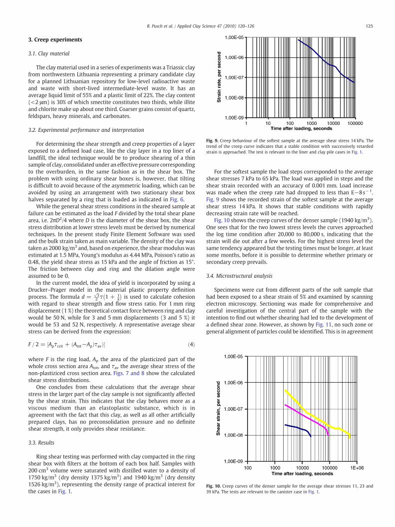
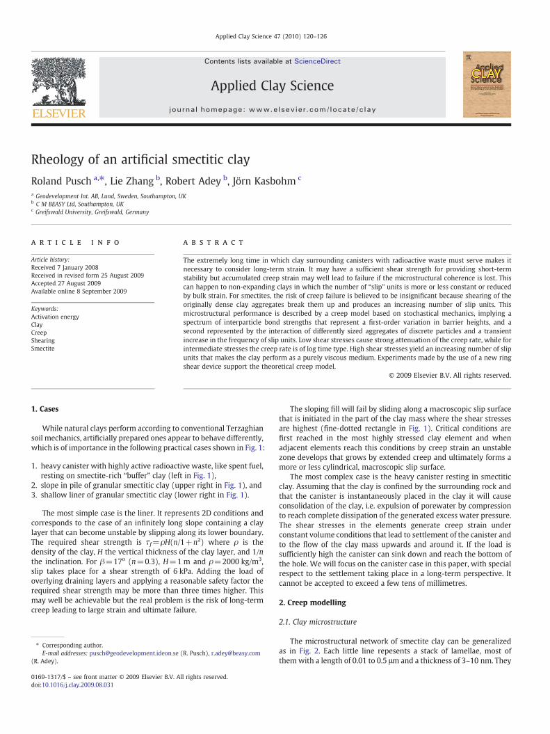
Fig. 9. Creep behaviour of the softest sample at the average shear stress 14 kPa. Thetrend of the creep curve indicates that a stable condition with successively retardedstrain is approached. The test is relevant to the liner and clay pile cases in Fig. 1.
Fig. 10. Creep curves of the denser sample for the average shear stresses 11, 23 and39 kPa. The tests are relevant to the canister case in Fig. 1.
125R. Pusch et al. / Applied Clay Science 47 (2010) 120–126
3. Creep experiments
3.1. Clay material
The claymaterial used in a series of experimentswas a Triassic clayfrom northwestern Lithuania representing a primary candidate clayfor a planned Lithuanian repository for low-level radioactive wasteand waste with short-lived intermediate-level waste. It has anaverage liquid limit of 55% and a plastic limit of 22%. The clay content(<2 μm) is 30% of which smectite constitutes two thirds, while illiteand chlorite make up about one third. Coarser grains consist of quartz,feldspars, heavy minerals, and carbonates.
3.2. Experimental performance and interpretation
For determining the shear strength and creep properties of a layerexposed to a defined load case, like the clay layer in a top liner of alandfill, the ideal technique would be to produce shearing of a thinsample of clay, consolidatedunder an effective pressure correspondingto the overburden, in the same fashion as in the shear box. Theproblem with using ordinary shear boxes is, however, that tiltingis difficult to avoid because of the asymmetric loading, which can beavoided by using an arrangement with two stationary shear boxhalves separated by a ring that is loaded as indicated in Fig. 6.
While the general shear stress conditions in the sheared sample atfailure can be estimated as the load F divided by the total shear planearea, i.e. 2πD2/4 where D is the diameter of the shear box, the shearstress distribution at lower stress levels must be derived by numericaltechniques. In the present study Finite Element Software was usedand the bulk strain taken as main variable. The density of the clay wastaken as 2000 kg/m3 and, based on experience, the shearmoduluswasestimated at 1.5 MPa, Young's modulus as 4.44 MPa, Poisson's ratio as0.48, the yield shear stress as 15 kPa and the angle of friction as 15°.The friction between clay and ring and the dilation angle wereassumed to be 0.
In the current model, the idea of yield is incorporated by using aDrucker–Prager model in the material plastic property definitionprocess. The formula d =
ffiffi3
p2 τ 1 + 1
k
� �is used to calculate cohesion
with regard to shear strength and flow stress ratio. For 1 mm ringdisplacement (1 %) the theoretical contact force between ring and claywould be 50 N, while for 3 and 5 mm displacements (3 and 5 %) itwould be 53 and 52 N, respectively. A representative average shearstress can be derived from the expression:
F = 2 = ½Apτcrit + ðAtot−ApÞτavÞ� ð4Þ
where F is the ring load, Ap the area of the plasticized part of thewhole cross section area Atot, and τav the average shear stress of thenon-plastiziced cross section area. Figs. 7 and 8 show the calculatedshear stress distributions.
One concludes from these calculations that the average shearstress in the larger part of the clay sample is not significantly affectedby the shear strain. This indicates that the clay behaves more as aviscous medium than an elastoplastic substance, which is inagreement with the fact that this clay, as well as all other artificiallyprepared clays, has no preconsolidation pressure and no definiteshear strength, it only provides shear resistance.
3.3. Results
Ring shear testing was performed with clay compacted in the ringshear box with filters at the bottom of each box half. Samples with200 cm3 volume were saturated with distilled water to a density of1750 kg/m3 (dry density 1375 kg/m3) and 1940 kg/m3 (dry density1526 kg/m3), representing the density range of practical interest forthe cases in Fig. 1.
For the softest sample the load steps corresponded to the averageshear stresses 7 kPa to 65 kPa. The load was applied in steps and theshear strain recorded with an accuracy of 0.001 mm. Load increasewas made when the creep rate had dropped to less than E−8s−1.Fig. 9 shows the recorded strain of the softest sample at the averageshear stress 14 kPa. It shows that stable conditions with rapidlydecreasing strain rate will be reached.
Fig. 10 shows the creep curves of the denser sample (1940 kg/m3).One sees that for the two lowest stress levels the curves approachedthe log time condition after 20,000 to 80,000 s, indicating that thestrain will die out after a few weeks. For the highest stress level thesame tendency appeared but the testing times must be longer, at leastsome months, before it is possible to determine whether primary orsecondary creep prevails.
3.4. Microstructural analysis
Specimens were cut from different parts of the soft sample thathad been exposed to a shear strain of 5% and examined by scanningelectron microscopy. Sectioning was made for comprehensive andcareful investigation of the central part of the sample with theintention to find out whether shearing had led to the development ofa defined shear zone. However, as shown by Fig. 11, no such zone orgeneral alignment of particles could be identified. This is in agreement

Fig. 11. Typical SEM pictures of the sheared, soft sample (J. Kasbohm).
126 R. Pusch et al. / Applied Clay Science 47 (2010) 120–126
with the theoretical investigation according to which the shear stressis uniformly distributed in the larger, central part of the sample wherespecimens had been extracted.
4. Conclusions
The main conclusions from the study are:
• The distribution of shear stresses in a clay sample with 20% smectitelocated in a ring shear box at 1–5% strain is uniform and similar inthe larger part as indicated by 3D FEM andmicrostructural analyses.
• The creep strain rate recorded at ring shear box testing evolved inagreement with the proposed creep theory, i.e. at low shear stressesthe strain rate dropped quickly and the strain reached a finite value,while at intermediate shear stresses the strain rate tended to followthe log time rate after an initial period of faster strain. For thehighest shear stresses the creep rate is also retarded but very long-lasting tests are required for finding out what it is in a perspective ofthousands of years and beyond that.
• Applying the results to the canister case the shear stresses inthe clay will be low despite the very high load, i.e. about 30 kPaat maximum, and the creep-controlled settlement will be retardedbut continues forever. The estimated settlement after E6 years is
on the order of 10 mm (Pusch and Adey, 1986), which is deemedacceptable.
• Considering the liner case in Fig. 1 and the experimentally foundcreep rates at relevant shear stresses one finds that for themaximumshear stress 6 kPa derived in Ch.1 for a bulk density of 2000 kg/m3,the creep rate will drop and ultimately die out. This will be the casealso for the third case in Fig. 1, the clay pile, since the average shearstress can be shown to be even lower than for the liner case becauseof the lower density, i.e. about 1800 kg/m3.
References
Buckle, A., Feltham, P., 1975. Logarithmic creep of copper and aluminium. Metal. Sci. 9,541–546.
Feltham, P., 1976. A simple stochastic model of low-temperature creep and stress-relaxation in solids. Proc. VII Int. Congr. Rheology, Gothenburg, Sweden, pp. 166–167.
Feltham, P., 1979. The inter-relationship: Earth science-material sciences. Mechanismsof Deformation and Fracture, vol. 29, No 42. Pergamon Press, London.
Pusch, R., Feltham, P., 1980. A stochastic model of the creep of soils. Géotechnique 30(4), 497–506.
Pusch, R., Adey, R., 1986. Settlement of clay-enveloped radioactive canisters. Appl. ClaySci. 1, 353–365.
Pusch, R., Yong, R.N., 2006. Microstructure of Smectite Clays and EngineeringPerformance. Taylor & Francis, London and New York.