Optimization of High Porosity Thermal Barrier Coatings Generated with a Porosity Former
7
Optimization of High Porosity Thermal Barrier Coatings Generated with a Porosity Former Jan Medrˇicky´, Nicholas Curry, Zdenek Pala, Monika Vilemova, Tomas Chraska, Jimmy Johansson, and Nicolaie Markocsan (Submitted June 5, 2014; in revised form October 26, 2014) Yttria-stabilized zirconia thermal barrier coatings are extensively used in turbine industry; however, increasing performance requirements have begun to make conventional air plasma sprayed coatings insufficient for future needs. Since the thermal conductivity of bulk material cannot be lowered easily; the design of highly porous coatings may be the most efficient way to achieve coatings with low thermal conductivity. Thus the approach of fabrication of coatings with a high porosity level based on plasma spraying of ceramic particles of dysprosia-stabilized zirconia mixed with polymer particles, has been tested. Both polymer and ceramic particles melt in plasma and after impact onto a substrate they form a coating. When the coating is subjected to heat treatment, polymer burns out and a complex structure of pores and cracks is formed. In order to obtain desired porosity level and microstructural features in coatings; a design of experiments, based on changes in spray distance, powder feeding rate, and plasma- forming atmosphere, was performed. Acquired coatings were evaluated for thermal conductivity and thermo-cyclic fatigue, and their morphology was assessed using scanning electron microscopy. It was shown that porosity level can be controlled by appropriate changes in spraying parameters. Keywords gas turbines, high temperature application, porosity of coatings, stabilized zirconia, thermal barrier coatings (TBCs) 1. Introduction The need for increasing of power and efficiency of gas turbines for land and aviation applications is inevitably connected with combustion of fuel at high temperatures. Superalloys that make up the turbine components are not able to withstand these high temperatures therefore ther- mal barrier coatings (TBC) have been used for several decades in order to provide thermal protection (Ref 1). However, conventional air plasma sprayed yttria-stabilized zirconia coatings are reaching the limit of their capabilities. Development of new generation coatings is required to push the technology to higher efficiency levels (Ref 2). Crucial factor for new TBCs is lowering of thermal conductivity of the coatings. It has been demonstrated that thermal conductivity of zirconia can be lowered by sub- stitution of a stabilizer; instead of standard stabilizing with yttrium oxide, another rare earth oxide can be used (Ref 3). Usage of dysprosium was shown to be suitable because of its greater ionic volume than yttrium, causing increasing phonon scattering and therefore lowering thermal conductivity, especially at high temperatures (Ref 4). Another way of lowering thermal conductivity can be done by introducing a high level of porosity into the coating (Ref 5). Porous structure of the topcoat is not only beneficial because of low thermal conductivity, but the presence of pores also enables the coating to accom- modate to the stresses generated during high temperature cyclic exposure (Ref 6). Besides low thermal conductivity of the topcoat; other important requirements are long coating lifetime and stable properties for the whole service life. The exposure of coatings to high temperatures during the service can lead to sintering, which causes densification of the coating and therefore loss of its beneficial thermo-mechanical properties (Ref 7). Reduction of the sintering rate is a key goal for coating development and previous work demon- strates it can be reduced by lowering the impurity level of the powder feedstock (Ref 8) and by introducing large globular pores, which can resist sintering better than del- aminations and small pores (Ref 9). Previous studies by the authors had demonstrated promising lifetime and low thermal conductivity of coat- ings generated with large globular pores. These pores were This article is an invited paper selected from presentations at the 2014 International Thermal Spray Conference, held May 21-23, 2014, in Barcelona, Spain, and has been expanded from the original presentation. Jan Medr ˇicky ´ , Czech Technical University in Prague, Prague Czech Republic; Nicholas Curry and Nicolaie Markocsan, University West, Trollha ´ ttan, Sweden; Zdenek Pala, Monika Vilemova, and Tomas Chraska, Institute of Plasma Physics AS CR, Prague, Czech Republic; and Jimmy Johansson, GKN Aerospace Engine Systems, Trollha ´ ttan, Darrasa, Sweden. Contact e-mail: [email protected]. JTTEE5 DOI: 10.1007/s11666-014-0214-y 1059-9630/$19.00 Ó ASM International Journal of Thermal Spray Technology Peer Reviewed
Transcript of Optimization of High Porosity Thermal Barrier Coatings Generated with a Porosity Former

Optimization of High Porosity ThermalBarrier Coatings Generated with a Porosity
FormerJan Medricky, Nicholas Curry, Zdenek Pala, Monika Vilemova, Tomas Chraska, Jimmy Johansson,
and Nicolaie Markocsan
(Submitted June 5, 2014; in revised form October 26, 2014)
Yttria-stabilized zirconia thermal barrier coatings are extensively used in turbine industry; however,increasing performance requirements have begun to make conventional air plasma sprayed coatingsinsufficient for future needs. Since the thermal conductivity of bulk material cannot be lowered easily;the design of highly porous coatings may be the most efficient way to achieve coatings with low thermalconductivity. Thus the approach of fabrication of coatings with a high porosity level based on plasmaspraying of ceramic particles of dysprosia-stabilized zirconia mixed with polymer particles, has beentested. Both polymer and ceramic particles melt in plasma and after impact onto a substrate they form acoating. When the coating is subjected to heat treatment, polymer burns out and a complex structure ofpores and cracks is formed. In order to obtain desired porosity level and microstructural features incoatings; a design of experiments, based on changes in spray distance, powder feeding rate, and plasma-forming atmosphere, was performed. Acquired coatings were evaluated for thermal conductivity andthermo-cyclic fatigue, and their morphology was assessed using scanning electron microscopy. It wasshown that porosity level can be controlled by appropriate changes in spraying parameters.
Keywords gas turbines, high temperature application,porosity of coatings, stabilized zirconia, thermalbarrier coatings (TBCs)
1. Introduction
The need for increasing of power and efficiency of gasturbines for land and aviation applications is inevitablyconnected with combustion of fuel at high temperatures.Superalloys that make up the turbine components are notable to withstand these high temperatures therefore ther-mal barrier coatings (TBC) have been used for severaldecades in order to provide thermal protection (Ref 1).However, conventional air plasma sprayed yttria-stabilizedzirconia coatings are reaching the limit of their capabilities.Development of new generation coatings is required topush the technology to higher efficiency levels (Ref 2).
Crucial factor for new TBCs is lowering of thermalconductivity of the coatings. It has been demonstrated thatthermal conductivity of zirconia can be lowered by sub-stitution of a stabilizer; instead of standard stabilizing withyttrium oxide, another rare earth oxide can be used(Ref 3). Usage of dysprosium was shown to be suitablebecause of its greater ionic volume than yttrium, causingincreasing phonon scattering and therefore loweringthermal conductivity, especially at high temperatures(Ref 4). Another way of lowering thermal conductivitycan be done by introducing a high level of porosity intothe coating (Ref 5). Porous structure of the topcoat is notonly beneficial because of low thermal conductivity, butthe presence of pores also enables the coating to accom-modate to the stresses generated during high temperaturecyclic exposure (Ref 6).
Besides low thermal conductivity of the topcoat; otherimportant requirements are long coating lifetime andstable properties for the whole service life. The exposureof coatings to high temperatures during the service canlead to sintering, which causes densification of the coatingand therefore loss of its beneficial thermo-mechanicalproperties (Ref 7). Reduction of the sintering rate is a keygoal for coating development and previous work demon-strates it can be reduced by lowering the impurity level ofthe powder feedstock (Ref 8) and by introducing largeglobular pores, which can resist sintering better than del-aminations and small pores (Ref 9).
Previous studies by the authors had demonstratedpromising lifetime and low thermal conductivity of coat-ings generated with large globular pores. These pores were
This article is an invited paper selected from presentations at the2014 International Thermal Spray Conference, held May 21-23,2014, in Barcelona, Spain, and has been expanded from theoriginal presentation.
Jan Medricky, Czech Technical University in Prague, PragueCzech Republic; Nicholas Curry and Nicolaie Markocsan,University West, Trollhattan, Sweden; Zdenek Pala, MonikaVilemova, and Tomas Chraska, Institute of Plasma Physics ASCR, Prague, Czech Republic; and Jimmy Johansson, GKNAerospace Engine Systems, Trollhattan, Darrasa, Sweden.Contact e-mail: [email protected].
JTTEE5
DOI: 10.1007/s11666-014-0214-y
1059-9630/$19.00 � ASM International
Journal of Thermal Spray Technology
Peer
Revie
wed

created by the use of a spray powder containing a poly-mer-pore former (Ref 5, 6, 9). While such mixed powdershave been used in the past for high temperature abradablecoatings, extensive work to optimize the coatings for TBCapplications had not been carried out.
Therefore, the aim of this paper has been to study theinfluence of spraying parameters during preparation ofhigh porosity TBCs generated with a porosity former. Adesign of experiments approach has been used to evaluatespray parameters that influence both thermal conductivityand lifetime of the thermal barrier coating.
2. Materials and Methods
2.1 Sample Production
For all the APS experiments reported in this study, aF4-MB plasma torch (Sultzer Metco, Wholen, Switzer-land) was used for deposition. The design of experimentsapproach was taken for creation of the test matrix with a2-level full factorial design being used. Three factors werechosen to alter in the spray process:
� Spray distance
� Powder feed rate
� Hydrogen Flow
The matrix results in a 9 run design with an additional tworepeat runs at the centre point; thus giving a total of 11 sprayruns as represented in Table 1. The experiments 9-11 servedto verify the stability of the process and they were sprayedusing parameters close to standard industrial depositionparameters of YSZ (Ref 4). In the other experiments,deposition parameters were either lowered (�) or increased(+) in comparison to the standard conditions 9-11.
Bond coats for all samples were produced using stan-dard AMPERIT 410 NiCoCrAlY powder (H.C. Starck,Munich, Germany), sprayed with F4-MB gun to thethickness 170 lm. Substrates used in this study wereHastelloy X in dimensions 25.4 9 25.4 9 2 mm formicrostructure and thermal conductivity measurements.For thermo-cyclic fatigue test samples in dimensions50 9 30 9 5 mm were used and coupons Ø25.4 9 5 mmwere coated for additional tests. All the substrates usedfor spraying were fixed to rotational fixture and grit-blas-ted and bond-coated in one run to achieve identical con-ditions for later application of the topcoat.
Ceramic coatings were produced with agglomerated &sintered (A&S) high-purity dysprosia-stabilized zirconiapowder mixed with polymer porosity former (SultzerMetco, Wholen, Switzerland). Polymer particles are addedto the powder to create microstructure with porosity notachievable with conventional powder. All the ceramictopcoats were sprayed to achieve 700 lm thick coating.
In-flight properties of the particles were measuredusing DPV 2000 (Tecnar Automation, Montreal, Canada).Measurement of temperature, diameter, and velocity of
individual particles entering the plasma jet were made forabout 5000 particles in the spray stream center that wasperformed by an automated routine for each condition.Mapping of the spray stream was performed using 5 9 5array with equispaced points with 5 mm separation andmeasuring approximately 300 particles in each location.
2.2 Isothermal Heat Treatment
In order to burn out the polymer from the coating andform a complex structure of pores, all the samples wereheat treated at 550 �C for 2 h in the air atmosphere.Additionally, one sample from each run was heat treated at1150 �C for 50 h, which leads to sintering of the structure,changes in thermal properties of the coating and formationof TGO at the interface. In this case, heat treatment isa simplification of aging which appears in real service.
2.3 Thermo-Cyclic Fatigue
Thermo-cyclic fatigue testing is performed as a form oflifetime assessment. Testing involves placing test samplesin the hot zone of a furnace at 1100 �C for 60 mins. Afterthe high temperature cycle is complete, the samples areremoved from the hot zone to a cooling stage wherecompressed air is used to force cool the samples to 100 �Cin under 10 mins. Failure criterion is deemed to be 20%spallation of the ceramic coating. In total, 3 samples weretested for each experimental run.
2.4 Thermal Conductivity
Thermal properties of As-sprayed samples (withburned out polymer) and Heat-treated samples wereevaluated using the laser flash technique. A Netzsch LaserFlash Analysis 427 (Netzsch Gebratebau GmbH, Ger-many) was used to measure the diffusivity of the system atroom temperature.
Two round disks Ø10 mm were water cut from coatedsamples for each condition (As-sprayed and Heat-treated)and used to evaluate thermal properties. As zirconia istransparent to light of the wavelength produced by LFAlaser, all the samples were coated with a thin layer ofgraphite before placing them to the testing device. Duringthe test, a laser pulse is fired at the back of the sample,heat generated by laser pulse is transferred through thesample and a measurement of the temperature change ismade on the front side of the sample by infra-red detector.Each measurement is an average of five shots. Diffusivitya (m2/s) of the system can be calculated using the fol-lowing formula (Ref 10):
a ¼ 0:138 � L2
tð0:5Þ ;
where L is the sample thickness and t(0.5) the time cor-responding to the half maximum increase in temperature.Thermal conductivity k (WÆm�1ÆK�1) can be easily calcu-lated from thermal diffusivity when specific heat capacityCp (JÆkg�1 K�1) and density q (kg/m3) are known usingthe formula (Ref 10):
Journal of Thermal Spray Technology
Peer
Revie
wed
k ¼ a � Cp � qIn this case, measurement of thermal properties of the fullsystem consisting of 3 layers, i.e., substrate, bond coat, andtopcoat was performed. The contribution of thermallygrown oxide layer for the heat-treated samples to thewhole is very small, owing layers low thickness (usuallyabout 5 lm), and can therefore be neglected (Ref 9). Toseparate thermal properties of the topcoat from themeasurement, it is necessary to know thermal conductiv-ities of the other layers; then thermal properties of thetopcoat can be calculated using data for the other layersand the rule of mixtures. The data for substrate and bondcoat layer used for the calculation were taken from theprevious study (Ref 5, 9).
2.5 Microstructure and Porosity Analysis
Samples produced for microstructure were sectionedusing a diamond wafering blade. The cross section of eachsample was mounted in low viscosity resin and polishedsemi-automatically using Buehler PowerPro 5000 (Bueh-ler, USA) and a standard TBC polishing method. Mor-phology of the samples was assessed using optical andscanning electron microscopy Hitachi TM3000 (Hitachi,Japan).
Porosity measurements were carried out using imageanalysis routine developed previously (Ref 11). In thisprocedure, 25 images at a magnification 8009 (usingSEM) were taken along the cross section of the coating tofully represent the microstructure. The images are thenprocessed using Aphelion image analysis software (AD-CIS, France). The image is converted into binary formatand an auto-thresholding technique is applied to avoiderrors caused by operator. The software is able to differ-entiate between cracks and pores using the height-to-length ratio, evaluate size distribution of pores, and alsocalculate the orientation of the cracks.
Porosity and pore size distribution was also determinedby mercury intrusion porosimetry (MIP) carried out onPoreMaster 33 GT (Quantachrome Corporation, BoyntonBeach, FL). For the measurements, coatings were de-tached from the substrates using nitro-hydrochloric acid.Substrate side of the coating surface was polished to re-move substrate residues. Prior to the measurement, coat-
ings were heat treated in a furnace at 120 �C to removeadsorbed water from the inner surfaces. Due to the smallsample volumes, blank cell correction was applied toincrease accuracy of the measurements.
3. Results and Discussion
3.1 Particle In-Flight Data
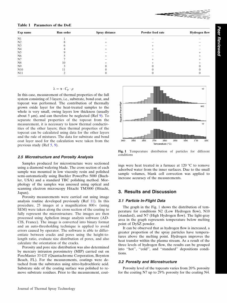
The graph in the Fig. 1 shows the distribution of tem-perature for conditions N2 (Low Hydrogen flow), N10(standard), and N7 (High Hydrogen flow). The light-grayarea in the graph represents temperature below meltingpoint of DySZ powder.
It can be observed that as hydrogen flow is increased, agreater proportion of the spray particles have tempera-tures above the melting point. Hydrogen improves theheat transfer within the plasma stream. As a result of thethree levels of hydrogen flow, the results can be groupedinto ‘‘hot’’, ‘‘cold’’, and ‘‘standard’’ depositions condi-tions.
3.2 Porosity and Microstructure
Porosity level of the topcoats varies from 20% porosityfor the coating N7 up to 29% porosity for the coating N4.
Table 1 Parameters of the DoE
Exp name Run order Spray distance Powder feed rate Hydrogen flow
N1 1 � � �N2 8 + � �N3 6 � + �N4 4 + + �N5 9 � � +N6 5 + � +N7 7 � + +N8 10 + + +N9 3 0 0 0N10 11 0 0 0N11 2 0 0 0
Fig. 1 Temperature distribution of particles for differentconditions
Journal of Thermal Spray Technology
Peer
Revie
wed

Total porosity and presence of cracks of the single coat-ings are displayed in the Fig. 2. There can be clearly seenthat the highest porosity levels are obtained for ‘‘cold’’conditions (experiment numbers N1-N4). Similarly lowporosity level was achieved for ‘‘hot’’ conditions; standardconditions give the coatings with medium porosity levelabout 26%. Despite the significant differences in totalporosity, only marginal changes were observed in varia-tion of number of cracks in the coatings presented inFig. 2.
Cross sections of the samples showing the differences inporosity are presented in the Fig. 3, 4, and 5. Presence oflarge globular pores is characteristic of the use of a poreformer and is apparent for coatings with high porositylevels, mean size of the pores decreases with increasing thehydrogen flow.
Total thickness of the topcoats was desired to be700 lm and the total number of passes of the torch neededto achieve full coating thickness was calculated from a fewfirst spraying passes. The real thickness of the topcoats isshown in the Fig. 6, together with thickness increase aftera pass of the spray torch.
3.3 Thermal Property Results
Thermal conductivity of the As-sprayed (AS) andHeat-treated (HT) samples evaluated by LFA at roomtemperature and their relative increase caused by sinteringprocesses during the heat treatment can be read from theTable 2. The study presumes that porosity level of thecoatings does not change significantly with heat treatment,based on previous study of the coatings generated withporosity former (Ref 9). This behavior is caused prefer-entially by presence of large globular pores in the coating,which are resistant to the sintering effect. The key factor,which causes the increase of thermal conductivity of theheat-treated samples, is micro-crack healing. Especially,the loss of horizontal cracks gives an increase in thermalconductivity.
The lowest thermal conductivity in the As-sprayedstate is not necessarily an indication of the best perfor-mance. The crucial factor is the sintering resistance of thecoatings, which varies significantly for presented coatings.The relative increase in the thermal conductivity after theisothermal heat treatment for the coating N2 (48%)compared to N4 (102%) that is shown in Table 2,
Fig. 2 Porosity level of the topcoats
Fig. 3 Cross section of the coating N7 containing low level ofporosity (20%)
Fig. 4 Cross section of the coating N10 containing medium levelof porosity (26%)
Fig. 5 Cross section of the coating N2 containing high level ofporosity (29%)
Journal of Thermal Spray Technology
Peer
Revie
wed

demonstrates a large range in sintering rate for the coat-ings presented in this study.
The dependence of thermal conductivity on totalporosity level of the coatings is presented in Fig. 7,showing that the level of total porosity is not the keyfactor for achieving of the coatings with extremely lowthermal conductivity, nor in maintaining that after thermalexposure.
The thermo-cyclic fatigue lifetime for all tested samplesis presented in Fig. 8. Failure in TCF testing is predomi-nately driven by bond coat oxidation and the growth of anoxide layer at the ceramic/bond coat interface. As allcoatings in this study were deposited on bond coats ofidentical composition, produced during the same sprayrun; relative differences in coating lifetime can be attrib-uted to influence of the ceramic top coat. There is notablespread in results for coatings N9, N10, and N11;although these coatings being repeat points should displaysimilar lifetimes. The coating thickness for N9 samplesmay result in a slightly higher lifetime in TCF testingrelative to the other two centre point; however, a standarddeviation of ±30 cycles is common in the TCF test. Theaccelerated failure of the sample N3 may be attributed toits considerably higher thickness (see Fig. 6), and there-fore increased stresses generated during the testing.Overall, the lifetime does not vary greatly within theexperimental samples.
Changes in phase composition of the topcoats, causedby heat treatment were evaluated using XRD. Diffraction
patterns of the feedstock, As-sprayed and Heat-treatedcoatings are shown in Fig. 9. Tetragonal zirconia stabilizedby dysprosia (DySZ) and Baddeleyite (monoclinic phase)were observed within the coatings. Volume fraction ofmonoclinic phase was calculated from the diffractionpatterns using Rietveld analysis. The feedstock materialcontains about 30% of Baddeleyite, which is reducedduring the deposition of the coating to 5% of Baddelyitefor As- sprayed samples. During heat treatment, theamount of monoclinic phase increases and saturates atabout 16% for Heat-treated samples, such behavior wasreported earlier (Ref 12) and is typical for high-puritydysprosia-stabilized zirconia powder. Volume changesconnected with phase transformation from tetragonalphase to monoclinic phase cause internal stresses withinthe coating and may accelerate evolution of spallationduring thermo-cyclic fatigue.
3.4 Model Fitting
Analysis of the design of experiments matrix was per-formed using the commercially available software Modde(Umetri AB, Sweden). Model fitting was performed usingpartial least squares, with some non-influential interactioneffects excluded for better model fitting. The observedversus predicted effects for the three most importantresponses are shown in Fig. 10 and 11.
Fig. 6 Total thickness of the topcoats for single experiments
Table 2 Thermal conductivity of As-sprayed and heat-treated samples
Exp name Porosity, % AS thermal conductivity, W/m K HT thermal conductivity, W/m K Relative increase, %
N1 26.96 0.69 ± 0.03 1.12 ± 0.02 62N2 26.96 0.64 ± 0.02 0.95 ± 0.01 48N3 25.75 0.80 ± 0.03 1.25 ± 0.03 56N4 29.23 0.51 ± 0.01 1.03 ± 0.06 102N5 20.23 0.84 ± 0.02 1.40 ± 0.02 66N6 21.32 0.61 ± 0.02 1.03 ± 0.03 68N7 20.04 0.65 ± 0.02 1.06 ± 0.02 62N8 20.84 0.64 ± 0.01 1.03 ± 0.03 60N9 23.53 0.65 ± 0.01 1.14 ± 0.02 76N10 22.83 0.72 ± 0.02 1.23 ± 0.06 71N11 26>48 0.74 ± 0.01 1.16 ± 0.01 55
Fig. 7 Dependence of thermal conductivity of the topcoats ontotal porosity level
Journal of Thermal Spray Technology
Peer
Revie
wed

Of general note in the presented results, there is a largevariation in results for N9, N10, and N11 spray runs. Sincethese runs are produced as replicated centre points, theresults demonstrate the variability of the process with thisparticular spray powder. This may be further attributed tothe in-homogenous nature of the produced coatings.
The overall fit for deposition rate and porosity is quitehigh. However, the variability in performance meansthermo-cyclic fatigue and thermal conductivity have alower level of predictability. Improvement of the modelmay be achieved through a number of additional sprayruns based on the edges of the design space rather thanonly the extreme corners as was carried out here.
4. Conclusions
Thermal barrier coatings for industrial application arerequired to have low thermal conductivity after thermalexposure and high cyclic life; both these qualities have tobe reached maintaining relatively high deposition effi-ciency to keep the process cost effective. In the presentedstudy, coatings with porosity level in the range from 20%to 29% were prepared using a porosity former containingpowder. By changing deposition parameters, porosity le-vel can be effectively controlled and coatings with favor-able properties obtained. It was demonstrated that
thermal conductivity of the coatings is highly dependenton porosity level and distribution of cracks and large poreswithin the topcoat. Thermal conductivity of all theas-sprayed coatings was evaluated to be very low—inthe range from 0.51 to 0.84 W/m K, but it increased to thevalues from 0.95 to 1.4 W/m K after heat treatment for50 h at the temperature 1150 �C. Microstructural featuresappear to influence the degree of sintering, and thereforeincrease in thermal conductivity; though this could not becorrelated to image analysis results. Thermo-cyclic fatigueproperties of the ceramic coatings showed variable life-
Fig. 8 TCF life of the samples
Fig. 9 Diffraction patterns of the feedstock and topcoats
Fig. 10 Observed versus predicted results for thermal conduc-tivity after heat treatment
Fig. 11 Observed versus predicted results for Thermo-cyclicfatigue
Journal of Thermal Spray Technology
Peer
Revie
wed
times within the expected limits of the test. Overall, theinfluence of process parameters on lifetime beyondthickness changes appears to be low.
Unfortunately, optimisation toward high depositionefficiency of spraying tends toward spray parameters thatnegatively influence the other performance factors. As anexample, coating N2 shows possibly the best performancein the reported tests. However, this coating is produced ata low deposition rate. In order to achieve all aims, acompromise would be required in performance factorsand further optimisation work would be required.
Acknowledgments
This work was partially supported by the Czech ScienceFoundation under Grant No. 14-36566G Multidisciplinaryresearch centre for advanced materials. The authors aregrateful for extensive technical support and help with spayingto Stefan Bjorklund, Production Technology Centre.
References
1. R. Miller, Thermal Barrier Coatings for Aircraft Engines: Historyand Directions, J. Therm. Spray Technol., 1997, 6(1), p 4-35
2. D. Stoverand and C. Funke, DIRECTIONS of the developmentof Thermal Barrier Coatings in Energy Applications, J. Mater.Process. Technol., 1999, 92-93, p 195-202
3. R. Harnacha, P. Fauchais, and F. Nardou, Influence of Dopant onthe Thermal Properties of Two Plasma-Sprayed Zirconia Coat-ings Part I: Relationship Between Powder Characteristics andCoating Properties, J. Therm. Spray Technol., 1996, 5(4), p 431-438
4. N. Markocsan, P. Nylen, and J. Wigren, Low thermal Conduc-tivity Coatings for Gas Turbine Applications, J. Therm. SprayTechnol., 2007, 16(4), p 498-505
5. N. Curry, N. Markocsan, X.-H. Li, A. Tricoire, and M. Dorfman,Next Generation Thermal Barrier Coatings for the Gas TurbineIndustry, J. Therm. Spray Technol., 2010, 20(1-2), p 108-115
6. N. Curry, N. Markocsan, L. Ostergren, X.-H. Li, and M. Dorf-man, Evaluation of the Lifetime and Thermal Conductivity ofDysprosia-Stabilized Thermal Barrier Coating Systems, J. Therm.Spray Technol., 2013, 22(6), p 672-864
7. F. Cernuschi, L. Lorenzoni, S. Ahmaniemi, P. Vuoristo, and T.Mantyla, Studies of the Sintering Kinetics of Thick ThermalBarrier Coatings by Thermal Diffusivity Measurements, J. Eur.Ceram. Soc., 2005, 25(4), p 393-400
8. L. Xie, M.R. Dorfman, A. Cipitria, S. Paul, I.O. Golosnoy, andT.W. Clyne, Properties and Performance of High-Purity ThermalBarrier Coatings, J. Therm. Spray Technol., 2007, 16(5), p 804-808
9. N. Curry and J. Donoghue, Evolution of Thermal Conductivity ofDysprosia Stabilised Thermal Barrier Coating Systems DuringHeat Treatment, Surf. Coat. Technol., 2012, 209, p 38-43
10. R.E. Taylor, Thermal Conductivity Determinations of ThermalBarrier Coatings, Mater. Sci. Eng. A, 1998, 245(2), p 160-167
11. J. Wigren, ‘‘High Insulation Thermal Barrier Systems—HITS’’,BriteEuram Project BE96-3226, 2002
12. N. Curry, W. Janikowski, Z. Pala, M. Vilemova, and N.Markocsan, Impact of Impurity Content on the Sintering Resis-tance and Phase Stability of Dysprosia- and Yttria-StabilizedZirconia Thermal Barrier Coatings, J. Therm. Spray Technol.,2014, 23(1-2), p 160-169
Journal of Thermal Spray Technology
Peer
Revie
wed