ORIGIN OF POROSITY IN CAST METALS - University of ...
191
/ / ORIGIN OF POROSITY IN CAST METALS. A Thesis submitted for the Degree of Doctor of Philosophy under Special Regulations. by JOI!.."l· C1J.!PBELL t M.A. (Cantab.) t M.Met. (Sheffield). Department of Industrial Hetallurgy, University of Birmingham. February 1967.
-
Upload
khangminh22 -
Category
Documents
-
view
2 -
download
0
Transcript of ORIGIN OF POROSITY IN CAST METALS - University of ...

/
/
ORIGIN OF POROSITY IN CAST METALS.
A Thesis submitted for the Degree of
Doctor of Philosophy under Special Regulations.
by
JOI!.."l· C1J.!PBELL t M.A. (Cantab.) t M.Met. (Sheffield).
Department of Industrial Hetallurgy,
University of Birmingham. February 1967.

University of Birmingham Research Archive
e-theses repository This unpublished thesis/dissertation is copyright of the author and/or third parties. The intellectual property rights of the author or third parties in respect of this work are as defined by The Copyright Designs and Patents Act 1988 or as modified by any successor legislation. Any use made of information contained in this thesis/dissertation must be in accordance with that legislation and must be properly acknowledged. Further distribution or reproduction in any format is prohibited without the permission of the copyright holder.

. • IMAGING SERVICES NORTH Boston Spa, Wetherby
West Yorkshire, LS23 7BQ
www.bl.uk
BEST COpy AVAILABLE.
VARIABLE PRINT QUALITY

PAGE NUMBERING AS
ORIGINAL

SYNOPSIS
A literature survey on the whole field of pore formation
is assenbled into the fo~ of a general theory of the causes
of porosity in castines. The conventionally accepted modes of
feeding arc assessed~ liquid-, mass-, and interd~ndritic
feeding; and t~lO furt!ler mechanbns arc proposcd: burst·- and
solid-feeding. The latter is invc3tieated theoretically usine
various flo\! models: elastic--p1astic, viscous, creep and
Binghan flow. A ne,,,, theory is pro~03ed for the origin of
layer porosity in ca3tings. Experir.lcntal work on a wide
variety of alloys: A1-Cu, Fe-C i Conplex Ui- and Co-base alloys,
cast both in air and in vacuum are investigated for the effect
of section thickness~ taper, and mould and neta1 tenperatures.
The fornation of porosity appears to chanec from a non
nucleation to a nucleation nechanism as section thickness
increases. A new method of interpreting radio~raphs based
upon a longitudinal line count reveals that solid feedine
becomes important in reducing porosity at high mould temperatures.
EXperincnts on the effect of cooposition of an alloy on porosity
cast doubt on the widely accepted thcory that the presence of
non-equilibrium eutectic liquid reduces porosity, but indicate
that the non·-oquilibriur.l freezing range of the alloy may be
the critical paraMeter. The effect of pressure on porosity
is investigated utilisin~ pressures below atmospheric; the
results arc inadequately explained by current theories and
arc discussed in tems of the nucleation and grouth of pores~
the effect would also appear to have considerable
industrial potential for reducing porosity in vacuum cast
components.
ACKllOHLEDGEHENTS •
The author is indebted to ~is supervisor. Dr. V. Kondic,
for much helpful criticism and for thc reading of this
manuscript; to Dr. G.E.J. Bennett for discussions on the
thermodynacic aspects of this work, to Professor P. Chadwick
and Dr. G. U. Rowe for help l-lith plasticity problems; to
Professor E.C. Rollason for the provision of the facilities
• of the Aitchison Laboratory; to the l1inistry of Aviation for
financial support of part of the work, and to the
University of Birningham for the grant of a Research FallovTship.
CONTENTS
Page Synopsis
Acknowledeer.:lents
Contents
List of Symbols
Introduction
4.
2. .A General Theory of Pore Formation
2.1. Non-nucleation 5b.
2.2. Homogeneous Nucleation 6.
2.2.1. Estirlation of zas pressure '>lithin 12. a bubble
2.2.2. Estimation of the maximum shrinkage 14. pressure
2.3. Heterogeneous Nucleation
2.2.1. Solid inclusions
2.3.2. Liquid inclusions
2.3.3. Complex inclusions
2.3.4. Caseous nuclei
15.
15.
18.
19.
20.
2.3.4.1. Gas bubbles in suspension 20.
2.3.4.2. Gas-filled crevices in 22. solids
2.4. Nucleation by Atomic Collisions
2.4.1. Cosmic rays
2.4.2. Radioactive decay
24.
26.
27.
2.5. Relation bet\Jeen Shrinkage nnd Gas Pressure 29. in Various Castinp,s
2.6. Growth of Pores 31.
2.6.1. Kinetics
2.6.2. Final size of pore
3. yeedi~~ Mechanis~~
3.1. Liquid
3.2. 11aas
3.3. Interclendritic
"i-
31.
33.
35.
35.
35.
37.
-ii-
3.4. Burst
3.5. Solid
4. !.actors Affecting Porosit~
4.1. Gas Content
4.2. Inclusions
4.3. Freezinf, Distance L, ~~d Temperature Gradient dT/dx
4.4. Alloy Cooposition in Relation to the Equilibrium Diagran
4.5. Rate of Solidification dm/dt
4.6. Superheat ~T s
4.7. Section Thickness
4.8. lfould Temperatura T m
4.9. Applied Pressure, Pa
4.10. Surface Tension~ y
4.11. Grain Size
4.12. Taper
4.13. Vibration during Solidification
4.14. Pouring Rate
5. 1!~_~'lUtitctive l!easurenent of Porosity
5.1. Feeding Distance
5.2. Pressure Tightness
5.3. Ultrasonics
5.4~ aetalloeraphy
5.5. Radiography
5.6. Density
6. Exp~ri~ental Procedure
6.1. The Hould
Page
41.
44.
52.
52.
55.
57.
58.
61.
65.
66.
67.
60.
69.
70.
71.
72.
72.
73.
73.
73.
74.
74.
74.
75.
77.
77.
G.1.1. Dcsi~ 77.
6.1.2. Construction of the lla.,< pattern 77.
6.1.3. Formation of shell moulds 78.
6.1.4. DC';l1axing and firing 78.

-iii-
6.2. Hould Pr~heating befor~ Pouring
6.3. Helting and Castine
6.4. t1~asur~ment of Density
6.5. Determination of Porosity
6.6. Radiographic Techniques
6.7. Solid Fe~ding Experiment
7. !!p'erimental Results
7.1- Effect of Mould Temperature and Superheat
7.2. Effect of Composition on Porosity
7.3. Uetallographic Examination
7.4,. Radiographic Examination
7.5. Effect of Taper on Porosity
7.6. Solid Feeding ·Experioent
7.7. . Analyses of Hat~ria1s
8. Pi~c£~gion of EX2erimental Results
8.1. ~olid F~eding
0.2. Eff~ct of liouid T~m;?erature T ) and Superheat flT 't:l
S
Z.3. Effect of Section Thickness
8~4. Effect of Composition
8.5. Effect of Taper
8.6. Effect of Pressure
8.7. On the Origin of Layer Porosity
Appendi<:.£!
1.
2.
3.
4.
5.
6.
7.
References
Cavitation at a Liquid-Liquid Interface
Surface Enerei~s of Borne Liquid ~1etals
Surface Energies of Solid Uetals
Interfacial Energies between Liquid and Solid Pure Metals
Surface Energies of Uon-neta11ic Liquids
Surface Energies of Non-m~tallic Solids
C"lltact longles b~t'1Cen vl!I.rif)U~3 Solids and Liquids
Page
78.
79.
80.
82.
a3. 84.
05.
85.
35.
8S.
87.
87.
38 •
33.
90.
92.
97.
99.
101.
102.
103.
106.
109.
110.
112.
113.
114.
115.
117.
U3.
121.
1.
2.
3.
4.
5.
6.
7.
8.
9.
10.
11.
12.
13.
···iv-
F I G U RES.
Equilibrium bubble radius versus internal gas pressure
Conditions for Pore Nucleation
Pf for Liquid Fe as a function of 02 and 112 contents
Pf
for liquid Cu as a function of 02 content
Increaoe in conce~tration of solutes at a solidification front
Conditions for pore nucleation in liquid Fe
Conditions for pore nucleation in liquid Cu
Heterogeneous nucleation at various interfaces
Effect of contact angle on heterogeneous nucleation
Feeding mechanisms
Conditions for Pore Nucleation showing Burst Feeding
Burst Feeding
Solid Feeding. Ps versus radius of liquid core
Page
11.
12.
14.
14.
14.
16.
16.
17.
13.
36.
42.
42.
47.
14. Plastic zones in a castine 48.
15. Equilibrium Diagran (after Bardot) 58.
16. Equilibrium Diagrans (after East\>100d and Davis) 53.
17. Effect of Eutectic Liquid (after Schener) 59.
18. Freezing Range versus Cooposition in Fe-'C system 60.
19. Effect of interface velocity on pore morphology 62. (after Chalmers)
19A. Results by Bogdanov 65.
20. Effect of mould and pouring temperature on 86. 3 carbon steels
21. Effect of mould and pouring temperature on 86. P.K.24 alloy
22. Effect of mould and pouring temperature on 36. P. K. 24 alloy
23. Effect of composition on porosity in Fe"C system 87.
24.
25.
26.
II " " " II " AI-Cu
Effect of taper on porosity in 0.25% C steel
II 11 1\ II " X40 alloy
:t ~7.
33.
a8.
27.
23.
29.
30.
31.
32.
33.
1.
2.
3.
4.
5.
6.
7.
" u.
-v-
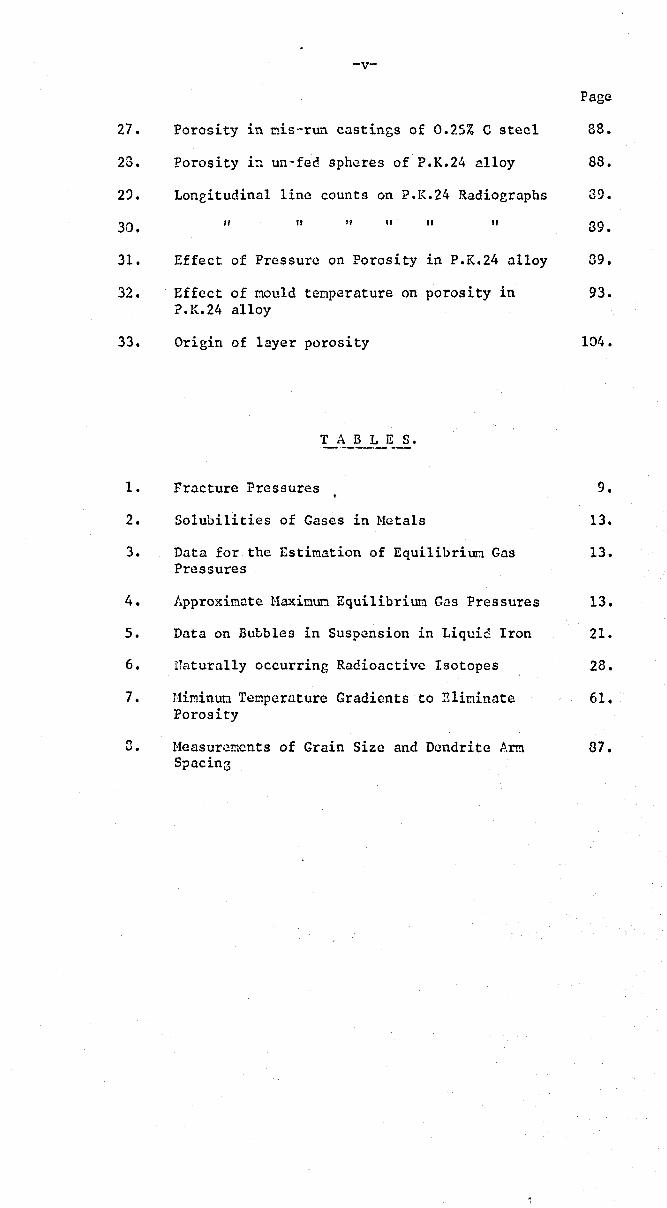
Porosity in nis-rlli' cnstings of 0.25% C steel
Porosity i:1 un· fed spheres of P.K.24 alloy
Loneitudinal line counts on P.K.24 Radiographs
" II " " " Effect of Pressure on Porosity in P.K.24 alloy
Effect of I:lould tenperature on porosity in P. K. 24 alloy
Origin of layer porosity
T A B L E S.
Fracture Pressures
Solubilities of Gases in Hotals
Data for the Estimation of Equi1ibriuo Gas Pressures
Approximate Haxioun Equilibrium Gas Pressures
Data on Bubbles in Suspension in Liquid Iron
naturally occurring Radioactive Isotopes
Himinuo Tempernture Gradients to Elininate Porosity
Heasurcments of Grain Size and Dendrite Arm Spacing
Page
88.
88.
39.
39.
39.
93.
104.
9.
13.
13.
13.
21.
28.
61.
87.
A
a. 1
a , a c 0
0: 0: 0: 'S' L
b
c
d
d o
E
h
L
L'
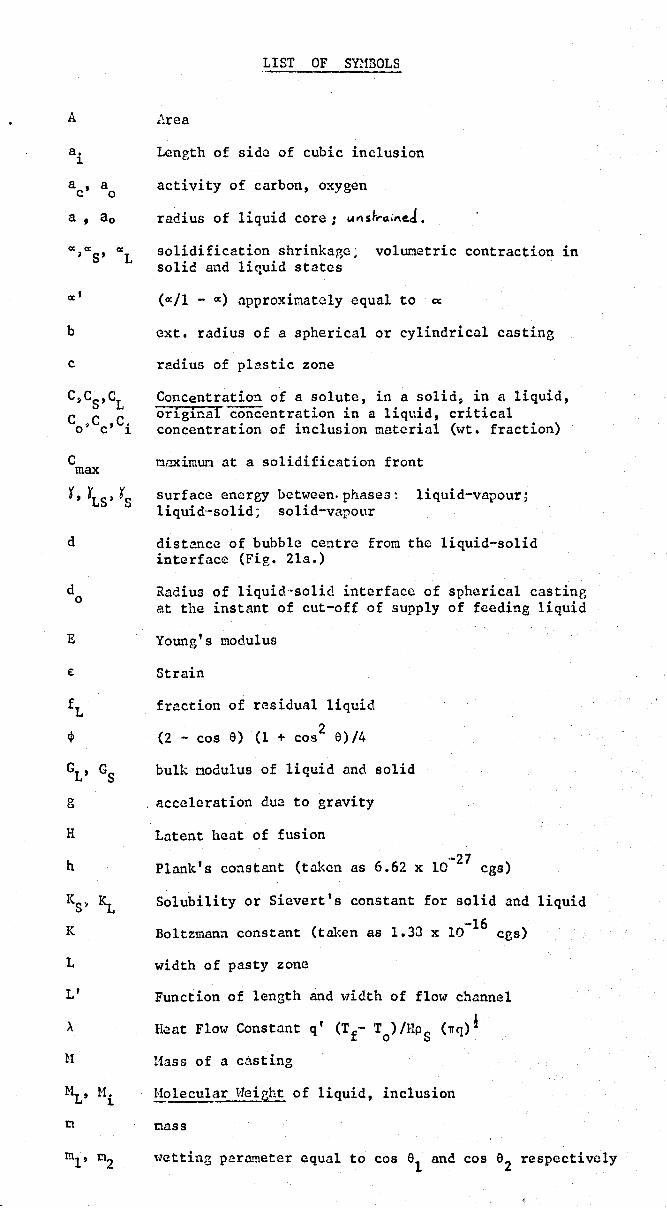
LIST OF SYHBOLS
l'..rea
Length of side of cubic inclusion
activity of carbon, oxygen
radius of liquid core; 1.("5~rll;ne.J.
solidification shrinkage: volumetric contraction in solid and liquid states
(0:/1 - 0:) approxinately equal to ~
ext. radius of a spherical or cylindrical casting
radius of plastic zone
Concentration of a solute, in a solid, in a liquid, original concentration in a liqldd, critical concentration of inclusion material (wt. fraction)
nnximum at a solidification front
surface energy between.phases~ liquid-vapour; liquid--solid; solid-vapour
distance of bubble centre from the liquid-solid interface (Fig. 2la.)
Radius of liquid--solid interface of spherical castine at the instant of cut-off of supply of feeding liquid
Young's modulus
Strain
fraction of residual liquid
(2 - cos a) (1 + cos2 a)/4
bulk nodulus of liquid and solid
. acceleration due to gravity
Latent heat of fusion
Plank.'s constant (taken as 6.62 x 10'-27 cgs)
Solubility or Sievert's constant for solid and liquid
-16 Boltzmann constant (taken as 1.33 x 10 cgs)
width of pasty zone
Function of length and ,,,idth of flow channel
Heat Flow Constant q' (T f- To)/HPS (1Tq)6
l1ass of a casting
!!..olecular V1eiat~ of liquid, inclusion
cass
,,,etting parruneter equal to cos a1
and cos 92 respectively
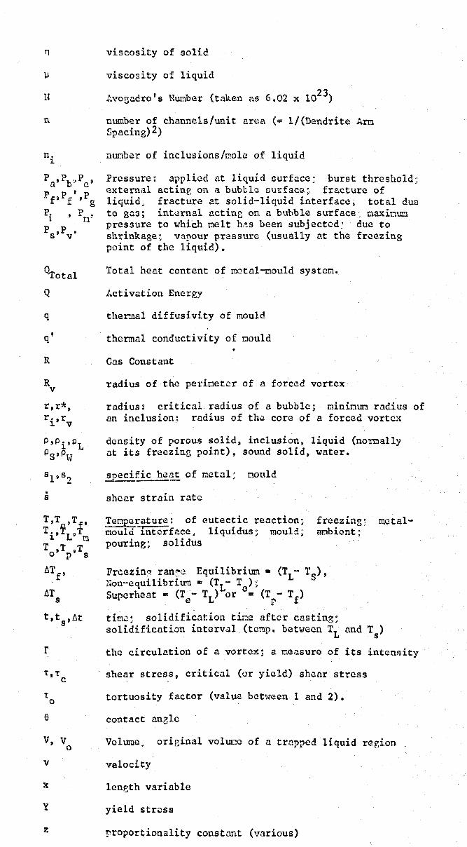
n
n
n. ~
o 'Total
Q
q
q'
R
R v
r,r*, r. ,r ~ v
P'Pi'PL PS»P~1
. s
T,T ,Tf
, T., ~LP T ~ m
T ,T ,T o p s
6Tf
,
6T s
t, t ,6t s
r
1:,1: C
1: 0
e
V, V 0
v
x
y
z
viscosity of solid
viscosity of liquid
23 Avogadro's Nunbcr (taken as 6.02 x 10 )
number of channels/unit area (= l/(Dendrite Arm Spacing) 2)
nunber of inclusions/mole of liquid
Pressure: applied at liquid ourfacc; burst threshold; external actine on a bubble ourface~ fracture of liquid; fracture at solid-liquid interface~ total due to gas; int~rnal act inc on a bubble surface ~ maxinU!'.1 pressure to whi'ch melt h.<1s been subjected: due to shrinkage; varour pressure (usually at the freezing point of the liquid).
Total heat content of mctal-mould system.
Activation Energy
ther.nal diffusivity of mould
thermal conductivity of mould
Gas Constant
radius of the perimeter of a forced vortex
radius: critical radius of a bubble; minimum radius of an inclusion~ radius of the core of a forced vortex
density of porous solid, inclusion, liquid (norcally at its freezing point), sound solid, water.
specific ~ of metal; noule!
shear strain rate
Temperature: of eutectic reaction; - -.---mould 1nterface. liquidus; mould;
pouring; solidus
freezing; anbient;
Frcezin~ ran~~ Equilibrium. (TL- T~), i-lon··equilibriu"ll • (TL- T ) ~ '-' Superheat = (T - TL) or e. (T - Tf )
e r
mctal-
tim~~ solidification tir.e after casting; solidification interval (temp. between TL and Ts)
the circulation of a vortex; a measure of its intcnRity
shear stress, critical (or yield) sh~ar stress
tortuosity factor (value between land 2).
contact nnelc
Volume; orieinal voluoe of a trapped liquid region
velocity
len~th variable
yield stress
proportionality constant (various)
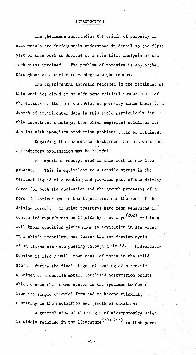
INTRODUCTIO~l.
The phenomena surrounding the origin of porosity in
cast metals are inadequately understood in detail so the first
part of this work is devoted to a sdentific analysis of the
mechanisms involved. The problem of porosity is approached
throu'Shout as a nucleatlon--and"prowth phenor.lcnon.
The experimentnl approach recorded in the remainder of
this work has aimed to provide some critical measurements of
the effects of the !!lain variables on porosity since there ill a
dearth of experi!!lental data in this field,particularly for
thin investment castin?,s, from which empirical solutions for
dealin~ with immediate production problems could be obtained.
Regarding the theoretical backp;round to this tyork some •
introductory explanation may be helpful.
An important concept used in this v70rk is nep,ati ve
pressure. This is equivalent to a tensile stress in the
residual liquid of a castine and provides part of the driving
force for both the nucleation and the 3rmlth processes of a
pore (dissolved r-as in the liquid provides the rest of the
drivin~ force). Hepative pressures have been eenerated in
t 11 d . 1·· ,.1 b (202) d· Con ro e eXpCr1!!lCnts on 1qU1 ... S y many "ays an 1S a
well-'knmm condition givine rise to cavitation in sea water
on a ship's propeller~ and durin~ the rarefaction cycle
of an ultrasonic wave passin~ through n 1 ir:uir:t. Hydrostatic
tension is also a well-knovffi cause of pores in the solid
state: curine the final sta~cs of tcstine of a tensile
specimen of a ductile mctal i localised deformation occurs
which causes thc stress system in the specitlen to depart
from its simple uniaxial form and to become triaxial;
resulting in t3C nucleation and erowth of cavities.
A 8eneral vic,,, of tha origin of microporosity ,yhich
. . • (203-·2~5) • 18 w1dely recorded in the lltcrature 18 that pores
'-1-
-2-
fom simply by shrinkage and subsequently fill ,V'ith gas \'1hich
prevents further liquid h~!alin? the pores. lloHever 'this is
fundamentally incorrect for as will be shotm later, shrinkage
alone is unlikely to nucleate a por~i an1 secondly, if gas
is present at all then e1enentary t~lcL.·Q(:-;n.::.~ic.,,; .:md kinetic:~
demand that the gas phase must contribute to the nucleation
process. Finally~ once the pore has nucleated and expanded
to reduce the elastic ener:w of the liquic··solid mass ~ then
under normal conditions the pore will not fill with liquid
again since this process would a~ain raise the free energy of
the system (the strain cncrE'Y which must be supplied to the
• casting can easily be show'n to be vastly in excess of the
surface ener?y of the pore which would be destroyed).
In considering the difficulties of feeding liquid
th h . h h (205).,. h rou~. a dendrlte mes many aut ors lnVOAe terms sue
as 'c <pi 11 ary forces'. &1 application of elementary physics
\V'i11 demonstrate that such forces are fiCtitiOU.1 since before
bubble nucleation no fr~e surfaces exist J and after
nucleati0!l the frcezinl!, liquid invariably exhibito a zero
contact angle tO~7"1rds the solid phase so :l:-:;ain floT' is
1 • d f h (220) unl1n eroc, by sur ace r enomcnon • Flov' is impeded of
course by viscous forces as will be discussed later.
On these grounds therefore, the above mentioned
theories of porosity formation \-lill not be further considored
in the prescnt work, and instead a fresh approach \'1i11 be
put fonlard.
A field of pore formation which is beyond the
Scope of the present t-Tork is of the initiation of pores
under the hi~h gas pressures resultinn: from various chemical
reactions, particularly in mould~et3l reactions, result in?
in surface and subsurface blo~\Th'1lcs. Also descrvin~

,-3",
, 'h b F1' (?06) h l' , ment10n 15 t.e paper y 1nn on t e qua 1tat1ve
evaluation of the susceptibility of various alloys to
shrinkap,e defects but this is an empirical test \orhich is not
easy to explain and a!),ain not really relevant to this work.

-4-
SECTION 1.
DISCUSSION ON TERMINOLOGY.
~ Gas and Shrinkage Porosity.
Throughout this work no distinction will be drawn between
porosity due to gas and that due to Shrinkage(13). Both are
cooperative in their effects upon nucleation growth and final size
of a pore. The exact contribution of each will vary as a result
of many faotors, partioularly the gas oontent of the solidifying
liquid. Dissolved gases cannot be entirely eliminated from liquids.:
1.2. Macroporosity.
Although it is feasible that a large cavity in a poorly fed
casting could be the result of ex~essive gas content of the melt,
most metals are degassed tolerabl3 ~ffectively prior to casting, and
the final size of a large cavity in a skin freezing metal (i.e., a
metal having negligible freezing range) is in general due to
shrinkage •. In a long freezing range alloy freezing under similar
conditions, a rather more extensive spongy volume of completely
interconnected interdendritic cavities results, bearing some
resemblance to severe microporosity. However, the cavity is better
described as a macropore (since it is a single cavity) whose
morphology has been dictated by the growth of the surrounding solid.
Gating and feeding methods are the normal means for controlling the
extent of macroporosity.
~ Microporosity.
Microporosity is often arbitrarily defined as being porosity
Which is invisible to the naked eye on a polished section, although
colOnies of micropores may be seen. However, all grades of pore
sizes between macro- and micro-porosity are found, and there is no
difference in principle between the nucleation and growth of either.
Nevertheless, some differentiation is possible since the
-5-
phenomenon oocurs exclusively in alloys having a finite freezing
range, and in gGneral it is not possible to greatly reduce the
percentage porosity due to micropores by conventional feeding.
Several forms of microporosity may be distinguished:
1.3.1. Centre line Shrinkage.
In parallel or plate-like sections the porosity is found to
be concentrated along the centre line. This form of microporosity
is not confined to long freezing range alloys ( o ATf ... 200 C or
more) but is in fact accentuated in alloys of intermediate or short
freezing range ( ~ Tf ... 10 to 500 C). Of all forms of micro-
porosity, this variety is most closely related to macro-porosity,
and thus greatly accentuated by deficiencies in feeding, and
exhibiting a large degree of interconnection between pores on the
centre line. Since the effect derives directly from solidification
geometry dictated by the shape of the casting, the remedy is to be
found in geometrical terms: a tapered section greatly reduces
centre lineshrinkage(7), while unidirectional solidification(8)
reduces it very much further.
1.3.2. Layer PorOSity.
Commonly observed in sections of light alloys(9) although
occasionally revealed in semi-microradiographs of steels. The
pores are found to be concentrated in layers parallel to the
Supposed position of the isotherms in the solidifying mass, and
are broadly distributed over the casting section.
1.3.3. Interdendritic PorOSity.
Very fine pores, mutually isolated, and broadly distributed
over the casting section resulting from micro-regions of trapped
liquid between secondary dendrite arms.
-5b-
2. A GENERAL THEORY OF PORE FORHATION.
g. Non-Nucleation.
( 2/+3) (?47-8) Fox and some later authors - suppose that~the
residual interdendritic liquid drains from the dendrite mesh,
leaving a networl~ of intercoUltected pores ,.,hieh closely
resemble the characteristic interdendritic appearance of micro-
porosity when observed in section.) This theory presupposes
the prior existence of a free liquid surface, such as at an
ingot top (in which caze the so-called microporosity is merely
an extension of the primary pipe) or adjacent to a previously
formed macropore:, in fact anywhere where the solidus isotherm
intersects a free surface of the casting at a late stage in
freezing. As the internal pressure in the casting falls, the
liquid which is 'still present at t!le surface of the casting will
be sucked into the interior to compensate for the contraction on
solidification. The fin:l.l result is a labyrinth of interconnected
channels cmereine in surface pinholes. ,Clearly, alloys of long
freezin?, ranee "-1i11 be particularly prone to the formt~tion of
porosity by this mechanism, especially in thin sections> at at /
'hot spots' ouch as re-entrant ::mgles (no metal-mou1d reaction
need be invok .ed to exp1a.in the occurrence of pinholes at such
1 (11) ocations, as is also suggested by Chalmers ).
Air entering, for instance, a steel casting in this
manner would not be expected to oxidise (or decarburise) much
more than thc~ entrance to the pinhole, since the oxygen ~Jould
be rapidly used up. Much of the nitrogen would probably also
be absorbed 'en route' so that the internal porosity would
contain nearly pure argon (and perhaps carbon monoxide)
thUs preservin~ the characteristic unoxidised appearance of
the central porosity.
-5-
2.2 HOMOGENEOUS NUCLEATION.
The condition for bubble stability in a liquid is expressed by
the relation p - p = 2 Y /r i e Q
•••• (I)
where P. ro1d P are the internal and external pressures respectively ~ e
acting on the bubble surface. The term 2 ~ /r gives the value of the
pressure difference across a spherical interface having an energy of
~ per unit area, and a radius r.
Pi is the sum of the partial pressures of all the gases and
vapours contained in the bubble
•••• (2)
Where for steel etc.
In a liquid at rest, the external pressure, P , is the sum of . e
the metallostatic head, Pd, the applied pressure at the liquid surface,
Pa (usually I atmosphere, or close to zero if in vacuum) and the
reduction in pressure due to solidification shrinkl\ge, -P , Thus s
.. P + Pd - P a s •••• (3)
substituting (2) and (3) into (1) end re-arranging
(P. - p ) = ( rp + P ) - (p + Pd ) .. 2 a /r ~ e gsa •••• (4)
Because of the negative sign, it is clear that an inorease in
(Fd + Pa) tends to suppress bubble formation (although Pd is normally
negligible _ a pressure of 1 atmosphere is equivalent to a depth of
1.3 m. of liquid. steel, or 3.8 m. of liquid Al) (which is a widely
appreCiated fact often exploited for this purpose by casting under a
high applied pressure. \. Since P is negative ond increases ..,..\ s
negatively the contributions of gas and shrinkage are seen to be additive
and to encourage bubble formation.
The bubble nucleation process has generally been approached
in terms of the maximum negative pressure that a liquid can withstand
before rupture occurs (i.e, a bubble forms) in the liquid. This tensile

-7-
strength of the liquid is knmm as its fracture pressure~ Pf'
Blake (3) and nak~shiI'.1a (4) eive critical revielV's of some of the theoretical
attempts at estimating this quantity; they may be broadly divided into
two categories (a) various methods based upon equations of state,
particularly Van der Waal's equation, and (b) the nucleation theories.
Other theories based on viscosity considerations by Brir.es et ale (58)
and on energy density considerations by Thorndike (53b) are carefully
assessed by Blake '''ho find.s the forner to be erroneous and the latter to
be insufficient. ?
(a) It "7as thou~ht that the a/v- term from the Van der ~laal' s
equation (p+ a/v2)(v - b) • RT rc~rescnted an 'intrinsic pressure' due
to the mutual attraction of the molecules of the liquid. and "7hich must
be exceeded before fraCture could occur. Estimates of this quantity
based upon critical constants~ and other phenomena such as heat of
vapourisation and compressibility all yield values of the order of 4
10 atmospheres for water. In order to obtain more reasonable values,
Temperley(5) has areucd that Pf
is not 8iven by the intrinsic pressure
but by the mininum on the Van der Faal' s isoth.:2rmals. tTsin,~ a~ain
critical constants, vapour pressure and compressibility, Pf
for water
llorks nut at 1000, 6,,800, and 1400 atmospheres respcctively(4). a
wide spread.
(b) The nucleation theories consider the detailed atomic
mechanism of fracture of the liquid. Follo"'ine Fisher's treatment (3) ;
a definite quantity of ,.,ork is associated with the reversible
formation of a bubble in the interior of a liquid. The creation of a
S?herical volume of rndius r requires \-70rk equal to (4/3)lfr3 P • e
The creation of the liquid"vapour intorfaco requires work equal to
41rr2y and the tlork required to reversibly fill the buhble \-1ith vapour
(or gas) of pressure P. is negative and equal to -(4/3)lfr3 P.. The 1 1
net energy required is therefore
B • 41rr2y + (4/3)lf r3 (p - P.) e 1
The variation of T,J tV'ith r can be shown to have a maximum
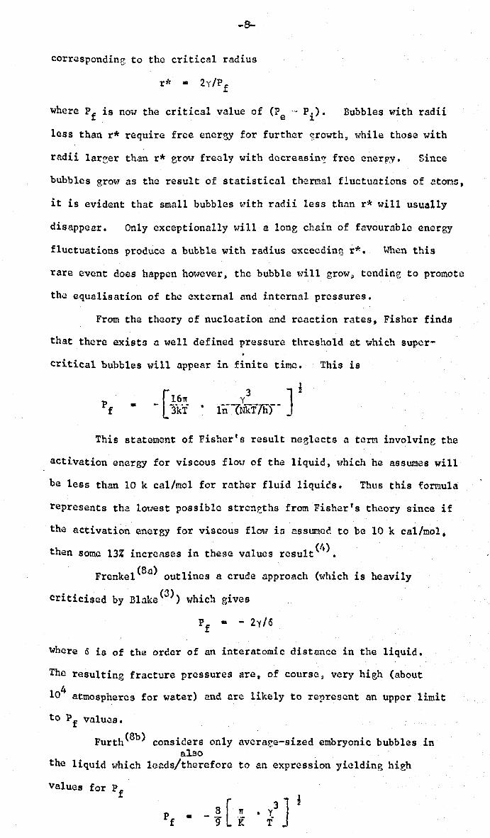
-8'-
correspondine to the critical radius
where Pf is now the critical value of (Pe'~ Pi)' Bubbles with radii
less than r* require free energy for further srowth» while those with
radii 1areer than r* erO\07 freely with dccreasin'!. free enerpy. Since
bubbles grow as the result of statistical thermal fluctuations of etoms,
it is evident that small bubbles t-rith radii less than r* ,.,rill usually
disappear. Only exceptionally will a long chain of favourable energy
fluctuations produce a bubble with radius excecdin~ r*. When this
rare event does happen hml7cver. the bubble \vi11 grow ~ tendin?, to promote
the equalisation of the external and internal pressures.
From the theory of nucleation and reaction rates, Fisher finds
that there exists a well defined pressure threshold at which super-
critical bubbles will appear in finite time. This is
•
This statement of Fisher's result neelects a term involving the
activation energy for viscous flou of th~ liquid, lvhich he assumes will
be less than 10 k cal/mol for rather fluid liquics. Thus this formula
represents tha lOllest possible streneths from Fisher's theory since if
the activation encrBY for viscous flow is assurnec to be 10 k cal/mol,
then Some 13% increases in these values result(4).
Frenkel(8a) outlines a crude approach (which is heavily
° 0 ° (3» h O h ° Crltlclsed by Blake W lC. glves
Pf • - 2y/o
where ~ is of the order of an interatomic distance in the liquid.
The resulting fracture pressures are, of course, very high (about
104 atmospheres for water) and arc likely to represent an upper limit
to Pf valu;i!.s.
Furth(8b) considers only avcracc-sized embryonic bubbles in also
the liquid which leads/therefore to an expression yielding hieh
values for Pf
3 J ~ • y T ..
Liquid Surface Tension Temp. ergs/em. oK
Helium 0.35 1.7
Ethyl Ether 17 300
:Benzene 29 300
Acetie Acid 28 300
Water 12 300
I1ereury 490 300
Aluminium 850 933 Copper 1300 1356
Iron 1850 1800
Rhenium 2700 3430
TABLE
Fracture Pressures (Atmospheres)
Furth~8) Modified DOring(4)
21.3 6.16
541 161
1,210 358
1,150 331
4,740 1,320
84,000 23,500
108,600 31,300
170,800 49,100
252,000 72.,300
321,000 91,600
Fisher(3) Bernath(6) Naximum Observed(40)
6.25 5.09
158 113
352 284 150
325 262 288
1,380 1,120 270
23,100 19,900 425
30,500 25,700
48,000 40,500 -- -!
10,800 60,000
90,500 16,000 ~.
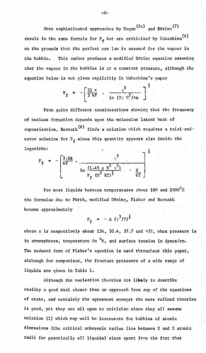
-9-
110re sophisticated approaches by Kagan (8c) and D6rin~ (7)
result in the sane fornula for Pf but are criticised by tJakeshit!l8(4)
on the erounds that the perfect r,as law is asswncd for the vapour in
the bubble. This author produces a modified Dorin~ equation assuming
that the vapour in the bubbles is at a constant pressure, although the
equation below is not given explicitly in tJakeshima t s paper
P f • - [.;2 kf . ___ y3 ____ ] I • In (2,( N2/Trm
From quite different considerations showinz that the frequency
of nucleus formation depends upon the molecular latent heat of
vapourisation, Bernath (6) finds a relation Hhich requires a trial"'and-
error solution for Pf since this quantity appears also inside the
logarithm.:
[
9.06 )'3 -1ZT·· 2?
In .(1.45 p N y'-~
P f (}13 RT) &
• 1I kT
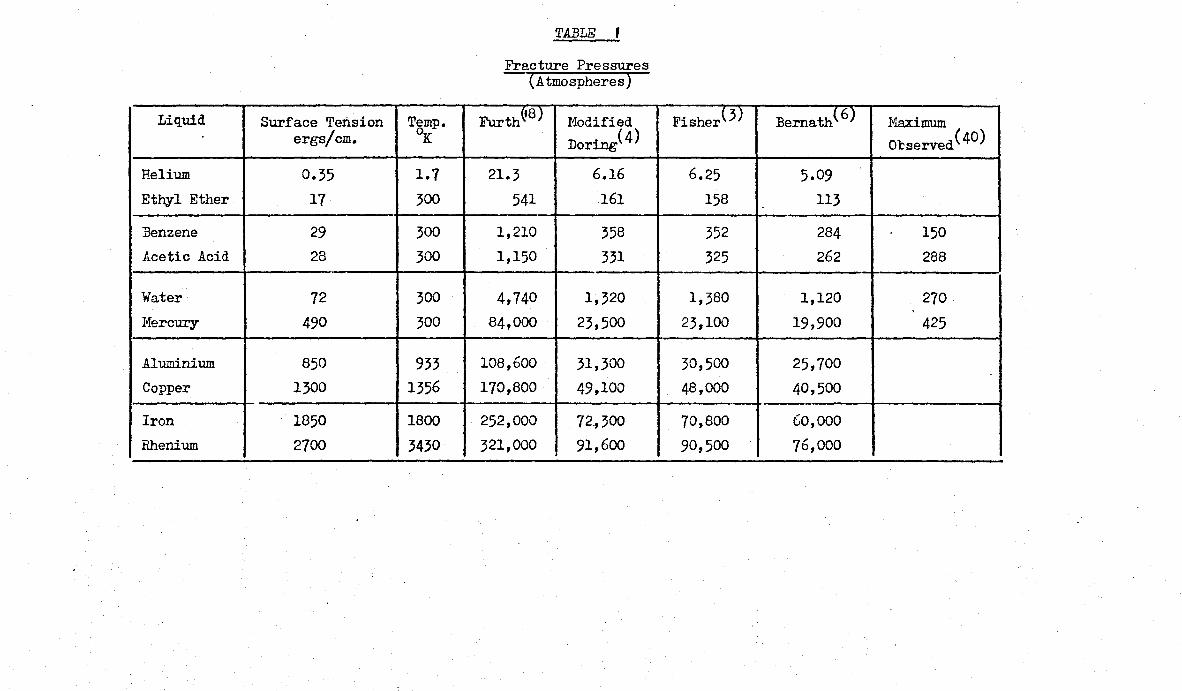
o For most liquids between temperatures about 100 and 2000 C
the formulae duo to FUrth, modified D6ring, Fisher and Bernath
becone approximately
where A is respectively about 134, 30.4, 31.1 and "'32, t~hen pressure is
in atmospheres, temperature in OK, and surface tension in dynes/cm.
The reduced form of Fisher's equation is used throur,hout this paper,
although for comparison, the fracture pressures of a wide ranee of
liquids are given in Table 1.
Although the nucleation ~haories are likely to describe
reality a good deal closer thnn an approach from any of the equations
of state, and certainly the agree~ent amonr,st the nore refined theories
is good, yet they are all open to criticiso since they all assume
relation (1) which m:iy tV'ell be inaccurate for bubbles of atomic
dimensions (the critical embryonic radius lies between 2 and 5 atomic
radii for practically all liquids) since apart from the fact that
-10-
such bubbles ney approximate poorly to a spherical for.m~ causin~ r
to be: uncertain and the lvhole theoretical Model to be ill-founded,
morc ioportant still C' for bubbles smaller than about 10M '50 atoT!lic radii
surface tension is progressively recuced and may beCOM~ negligible
for bubbles of one aton radius.
This variation of surface tension with radius i9 investi~ated
, b 1 h (193"200) b ' '. 11 l' d theoret1cally y severa aut ors ut 1S crit1ca y app 10 to
bubble nucleation only by Hake sh it:la <l+) who produces some
modified values of Pf deduced from van der Haal's equation. These
Pf values are chosen for modification because of a 'maximum' nne
'minimum' pressure concept '''hich arises in his analysis which are
tentatively identified \\lith the turning points on the van dar Haal
isotherms. This attempt to app,ly this analogy in a consistent
lVay unfortunately neglects the fact that the equRtion of state
approach can never yield accurate Pf values. since also the maxi~UM
pressure term disappears from the equations anyway it would obviously
be better to introduce a minimum pressure as {krivec from one of
the better nucleation theories. The application of t-Jakeshima' s
analysis is complicated~ howcver~ and is not pursued here - modified
values would possibly be a factor of 2 Imver. Pf
values calculated direct
from Fisher's formula are used throughout this \·10rk. Although tha Pf
BUBBLE RADIUS (e.M.)
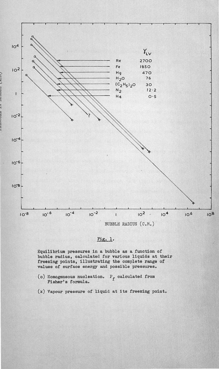
Fig. 1.
Equilibrium pressures in a bubble as a funotion of bubble radius, oalculated tor various liquids at their freezing points, illustrating the oompl te range of values of surfac energy and possible pre sure •
(0) Homogeneous nuoleation. Pf oalculated from Fisher' 8 formula.
(x) Vapour pressure of liquid at its freezing point.
10 6 106
-11-
values may be therefore rather high, they are certainly correct to within
about a factor of five, and the relative values should be quite reliable.
A summary of data on a wide variety of liquids a.t their
freezing pOints is given in Figure 1. The liquids are free of external
constraint, P , so that the lines are limited in extent by the vapour e
pressure of the liquid at its freezing point. An application of a
reduced pressure, Pe , would extend the lines as far as desired. Towards
* smaller radii the equation bubble size is limited by r (An application
of Wakeshima's analysis to these lines shows a bending towards the
-6 ) horizontal below about 10 cm radius •
A further complication which has been apparently overlooked in
the theoretical approaches at evaluating the fracture strengths of
liquids is the variation of surface tension with pressure. The
application of a high positive pressure to a liquid surface brings a
large number of molecules within reach of the surface (and is practically
equivalent to the presence of a second liquid) and so diminishes the net
inward attraction on the surface layer of atoms. Kundt(9) found by
experiment that the surface tension of several low melting point liquids
was linearly decreased by up to 50% at 150 atm. Additionally, at high
tensile stresses in the liquid the increased separation of the atoms in
the liquid should also reduce surface tension. Thus P f will be
reduced whether nucleation occurs solely due to either gas or
shrinkage. In the absence of experimental data for the effect of
pressure on surface tension of liquid metals this refinement is
neglected. The effect is likely.to be more important for low melting
point liquids.
It tollows from the above considerations that the oondition for
homogeneous nucleation in the liquid is
P - P. = Pf e ~ ••• (11)
UJ .J m en :::> cO
Z 0
UJ a: :::> 11'1 11'1 UJ a: 0.
.J < Z 0: UJ l-X au
Po A
0
-P.' r
-P. f
c~----------~~--------------~o
~'" 0 ~~ ~
<c..; ,0 o~ oC:> ~
~ ~~ A-. ~ 0"V.
~,
~~~~ ~~ 0v
~~
v'" ~O
~~ oC:>
O~ • ~
GAS PRESSURE IN BUBBLE
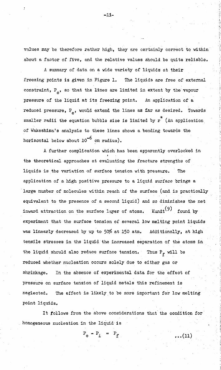
Fig. 2 .
Sohematic representation of the oooperativ effects of gas and shrink on the nuoloation of pores .
Adapted from Whittenberger and Rhin s .
-12-
which becomes, since Pa and Pd of equation (4) o~e often negligible
P +P = Pf g s ••• (12)
Clearly, in a gas-free melt Pf equals the external negative pressure
which is required to create a pore, r~d in an unconstrained liquid Pf
equals the internal positive pressure due to gas. This cooperative
effect of gas and shrinkage is represented in Figure 2. where the line
showing the beginning of homogeneous nucleation is a plot of equation (12).
Following the ideas of Whittenberger and Rhines(2); as
solidification proceeds in a casting the pressure in the residual liquid
falls because of shrinkage, and the gas content (and therefore the
equilibrium gas pressure) increases because of segregetion, so that
some curve AB is followed (Figure 2.). The equation of this curve is
deduced in Section 3. When the point B is reached, conditions for
nucleation are satisfied (equation 19) so that a bubble is formed.
The bubble expands rapidly to an equilibrium size and relieves the stress
in the casting so that the pressure rises to C. Further nucleution can
now only occur if the gas segreg!1tion increases to such a point that the
nucleation condition is met again at D.
2 2 1 Estimp,tion of Gas Pressure wi thin a :Bubble. • •
Considering the segregation of gases in a little more detail:
The rejection of various solutes by an advancing planar solidification
front is represented schematically in Figure ,., and some partition
coefficients, K, for gases in metals are given in Table II. (the scatter
in the soluiility ~ata is rather large so that some coefficients are
probably only accurate to within a factor of 2). The peak
concentration at the interface Cmax is related to the concentration
in the bulk of the liquid, Co, by the well known equation
C ... C /K max 0" .
IIydrogen and nitrogen are seen to be concentrated by a factor of 2 or 3
for most metals, although hydrogen in aluminium is increased by 10
times.
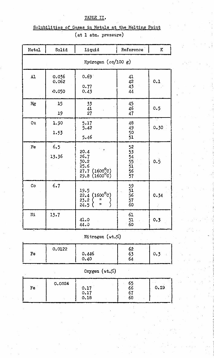
TABLE II.
Solubilities of Gases in Metals at the Melting Point
(at 1 atm. pressure)
I I ,
I l-Ietal Solid Liquid I Reference K
Hydrogen (ce/100 g)
Al 0.036 0.69' 41 0.062 42 0.1
0.77 43 .0.050 0.43 44
Mg 15 33 45 41 46 0.5
19 27 47
Cu 1.90 5.17 48 5.42 49 0.30
1.53 50 5.46 51
Fe 6.5 52 20.4 • 53
13.36 26.7 54 30.2 55 0.5 25.6 51 27.7 ~16000C~ 56 29.8 16000c 57
Co 6.7 59 19.5 51 22.4 ~16000Cl 56 0.34 23.2 " 57 24.5 " 60
Ni 13.7 61 41.0 51 0.3 44.0 60
Ni trogen (wt.1G)
0.0122 62 I 0.3 Fe 0.446 63 0.40 64
Oxygen (wt.%)
0.0524 65 Fe 0.17 66 0.19
0.17 67 0.18 68
I
Gas -
H2
N2
O2
co
CO2
H2O
H2S
S02
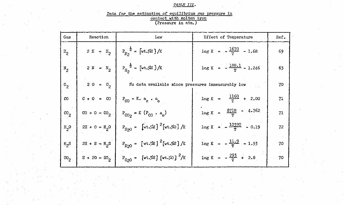
TABLE III.
Data for the estimation of equilibrium gaS pressure in contact with molten iron
(Pressure in atm.)
Reaction Law Effect of Temperature
1 _ 1670 2 H = R2 P "2 = [wt.rlI) /K log K = - 1.68 H2 T
2 N = N2 PH i = [wt.1~] /K log K 188.1 - 1.246 = - T 2
2 0 = °2 No data available since pressures immeasurably low
C + ° = CO PCO = K. ac • ao log K = 1160 - + T 2.00
. CO + ° = CO2 PC02 = K (PCO • ao) log K 8718 - 4.762 = T
2H + ° = H2O PH20 = [wt.flI] 2 [wt.1~] /K log K lO~2° - 0.19 = - T
2H + S = H2S PH2D = [wt.fdIJ 2[wt.%S] /K log K = _ 1~.2 _ 1.93
S + 20 = 802 PS20 = [wt.1~J fwt.1iD) 2/K log K = _£22. + T
2.8
Ref.
69
63
70
71
71
72
70
70
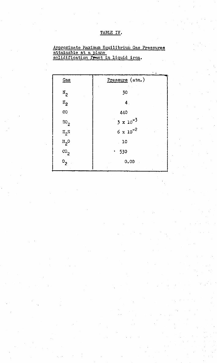
TABLE IV.
~oximate Maximum EQuilibrium Gas Pressures attainable at a plane solidificationf~nt in liquid iron.
~ Pressure (atm. )
N2 30
H2 4
co 440
S02 3 x 10.3
II S 2 6 x 10 ... 2
H2O 10
CO2 . 530
°2 0.00
*'
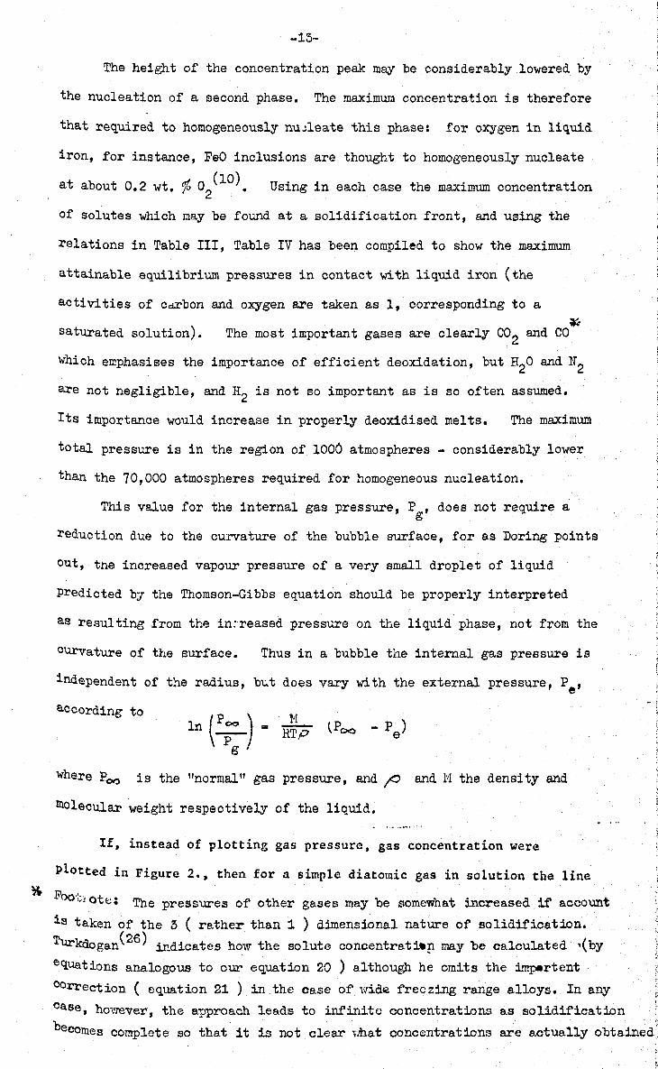
-15-
The height of the concentration peak m~ be considerably lowered by
the nucleation of a second phase. The maximum concentration is therefore
that required to homogeneously nu~leate this phase: for oxygen in liquid
iron, for instance, FeO inclusions are thought to homogeneously nucleate
at (10) at about 0.2 wt. ~ 02 .' Using in each case the maximum concentration
of solutes which may be found at a solidification front, and using the
relations in Table III, Table IV has been compiled to show the maximum
attainable equilibrium pressures in contact with liquid iron (the
activities of cdXbon and oxygen are taken as 1, corresponding to a
saturated solution). * The most important gases are clearly CO2 and CO
which emphasises the importance of efficient deoxidation, but H20 and N2
are not negligible, and H2 is not so important as is so often assumed.
Its importance would increase in properly deoxidised melts. The maximum
total pressure is in the region of 1006 atmospheres - considerably lower
than the 70,000 atmospheres required for homogeneous nucleation.
This value for the internal gas pressure, ~gt does not require a
reduction due to the curvature of the bubble surface, for as Doring points
out, the increased vapour pressure of a very small droplet of liquid
predicted by the Thomson-Gibbs equation should be properly interpreted
as resulting .from the in:reased pressure on the liquid phase, not from the
curvature of the surface. Thus in a bubble the internal gas pressure is
independent of the radius, b~t does vary with the external pressure, Pet
according to ln (P;o ) = R~P t p 0<0 - P e)
g
where Poo is the "normal" gas pressure, and;O and 1'1 the density and
moleOular weight respective~ of the liquid.
If, instead of plotting gas pressure, gas concentration were
plotted in Figure 2., then for a simple diatotnic gas in solution the line
li'oO':;lotC: The pressures of other gases may be somewhat increased if account
is taken of the 5 ( rather than 1 ) dimensional nature of solidification.
Turkdogan(26) ind.icates how the solute concentrati-.p. may be calculated '(by
equations analogous to our equation 20 ) although he omits the impertent
COrrection ( equation 21 ) in the case of vdde freezing range alloys, In any
case, however, the approach leads to infinite concentrations as solidification
becomes complete so that it is not clear vihat concentrations are actually obtained
WT % OXYGE N OR N / TROGE N o -02 -04 -06 ·08 -10 -12 -/4 -/6 -/8 -20
,..., ~ I< .....
w a: :;) -20000 11'1 , 11'1 UJ a:: Cl.
UJ -30,000 a:: :;)
I-U < 0: u. -40,000
-50,000
-60,000
-70,000
, I
N _____________ 2 ---
HETEROGENEOUS NU CLEAT/ON ON AI2
03
O2
- - - - - - - - -
, ,
HOMOGENEOUS
", N2
NUCLEAT ION
I
1
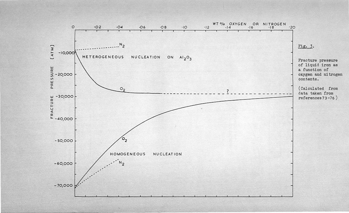
Fig. 3.
Fracture pressure of liquid iron as a function of oxygen and ni trogen contents.
(Calculated from data taken from references73-76 )
UI cr :> \II \II W ex: -20,000 Q.
w a: :> ... u <
" I.L
-30,000
-40,000
-50,000
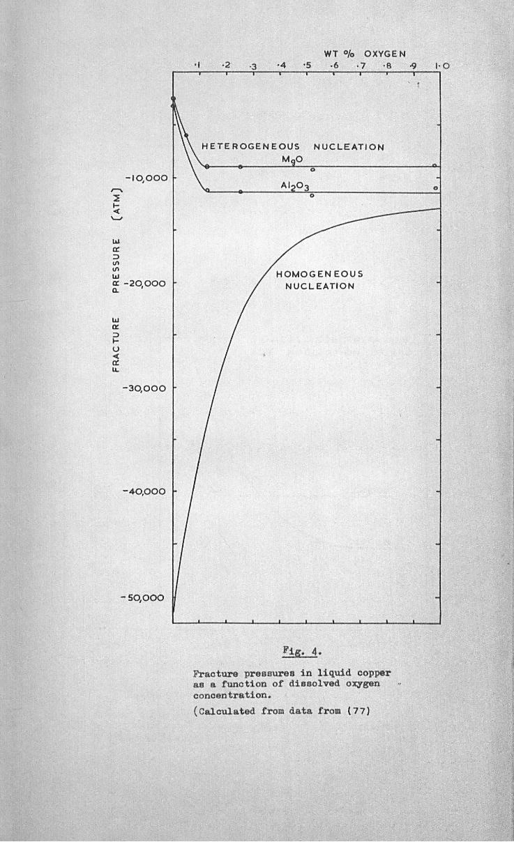
WT % OXYGE N
r-__ ·TI __ -,'2 __ ~·3r-__ ·T4 __ ~'5 __ ~.~6 ___ '~7 ___ '~8~~~~~1'0
HETEROGENEOUS NUCLEATION
MO o
o
HOMOGENEOUS NUCLEATION
Fraoture pressures in liquid oopper as a funotion of dissolved o~gen oonoentration.
(Caloulated £rom data from (77)
• 1
o
-14-
representing the threshold of nuoleation would become a parabola (in
contrast with the straight line proposed schematioally by Whittenberger
and Rhines(2» because of Sievert's Law
pi. g
Suoh considerations apply to a simple system sueh as hydrogen
in liquid iron. With SUrfaoe active gas, however, the surface tension
is reduced causing Pf to .be a function of gas content as is demonstrated
in Figures 3. and 4.
Estimation of the Maximum Shrinkage'PressBEe.
The author has shown elsewhere(39) that the maximum possible
negative pressure in a casting of pure iron is in the region of
-1,500 atmospheres because of plastio collapse of the oasting under
the internal tension,
Thus it seems that neither gas nor shrinkage alone, nor even
in combination can meet the very stringent conditions defined by
equation (12) so that homogeneous nucleation does not eeem to be a
feasible mechanism for the creation of p~res in iron castings.
Similar considerations show that this conclusion applies to aluminium
castings, and perhaps to castings in any metal.

2.3 HErEROG~NEOUS NUCLEATION.
It is believed that nucleation of bubbles occurs at certain
preferred sites in the liquid. These sites may consist of the
boundary of the liquid. with a solid, a seoond immiscible liquid, or a
gas phase. These are discussed in turn.
2.~.1 Solid Inclusions.
Following Fisher's treatment(3) of heterogeneous nucleation, a
bubble at the interface of the solid and liquid phases assumes the
shape shown in Fig. aA 1 LV' ~ SV and ~ 8L represent the liquid
vapour, solid-vapour and solid-liquid interfacial energies respeotively.
The value of d corresponding to a minimum energy can be seen to be
d/r .. - Cos e - ( K SL - ~ 8V)/ ~ LV ••• (13)
where e is the normal contact angle measured by a sessile drop
technique. Considering the ruaximmn value of tha energy ~equired to
produce a bubble of critical size leads to a value of the fracture
pressure, Pr', at the interface
P , .. -f ••• (14)
where ¢ .. (2-C088 ) (1 + Cos e )2/4 ••• (15)
Equation (14) differs from (8) in that a factor of ¢i has been
introduced and the number of interface atoms 6 N2/ 3 (assuming tbat
the liquid is bounded by the solid in the form of a cubical container)
appears in place of N in the logarithm. Thus
P , "" I~ (In N kT~h )! 1; In 6 N2 3 kT/h . • •• (16)
or approximately for temperatures between 10000 C and 2000°0
.. 1.12;) ••• (17)
A pl:st of equation 17 is given in Figure 9 • We may further modify
equation 14 by ~ssuming that one mole of liquid contains a

2~000 ~-------r--------r-----~~~----~r---~~~------~--~--~~--,
10,000 -III Q: =>-10000 \I) ,
\I)
III Q: Q..
...J-20000 '0( ,
~ Q: 1&J .... >< 111- 30,000 I
-40,000
-SO,OOO
- 60,000 I
- 70,000
o
I
I I
MAXIMUM GAS PRESSURE
MAXIMUM SHR I NKAG e:
PR.ESSURE
10,000 20,000 30,000 40,000 50,000 60,000 INTERNAL GAS
Figure 6.
PRESSURE, PI
Conditions for pore nucleation in liquid iron, heterogeneously on solid inclusions , and homogeneousl y in liquid iron and liquid inclusions. (Values for surface energy , '( ~ in ergs/ cm2) •
70,000 (ATM)
I~OOO r-------~~~~--~--~~------~~--------~----------~------~~
o
\u 0:: '::) 11\ 11\
\u-20000 0:: ' It
-I 'C(
Z Q:
~-30,oOO )( III
-40,000
-sqooo
I'
, , " , ,
-6~000 ~----------~----------~--------------~----------------~~----------~-----------~ o 10,000 20,000 30,000 40,000 50,000 60,000
INTERNAL GAS PRE5SURE ~ (ATM)
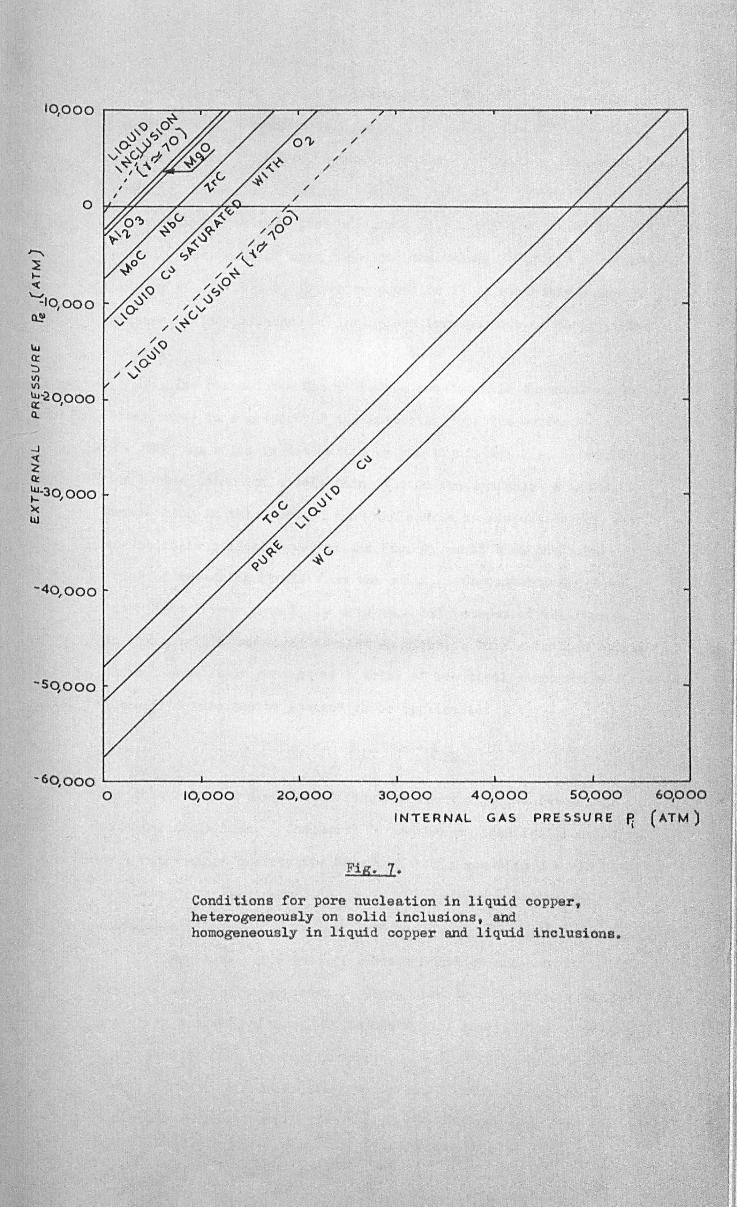
Fig. 7.
Conditions for pore nucleation in liquid copper, heterogeneously on solid inclusions, and homogeneously in liquid copper and liquid inclusions.
... 16-
concentration Ci
of inclusion material. If the inclusions are
cubical and of average side a1 and if 1\ and :Hi are the moleoular
weights of the liquid and inolusions respectively then the total
number of. interfaoe atoms now is 6 (ci J!VaiPi 1/3)(~~/}!i)2/3. However in the extreme case of c. = 1 (i.e. 100% inclusion) and
.' 1
ai = 10-8 om (smaller than one atom) the value of Pf' is decreased
only by 9%, so that Pf ' given by equation 14 is evidently a useful
measure of the influence of inclusions irrespeotive of their number
or size.
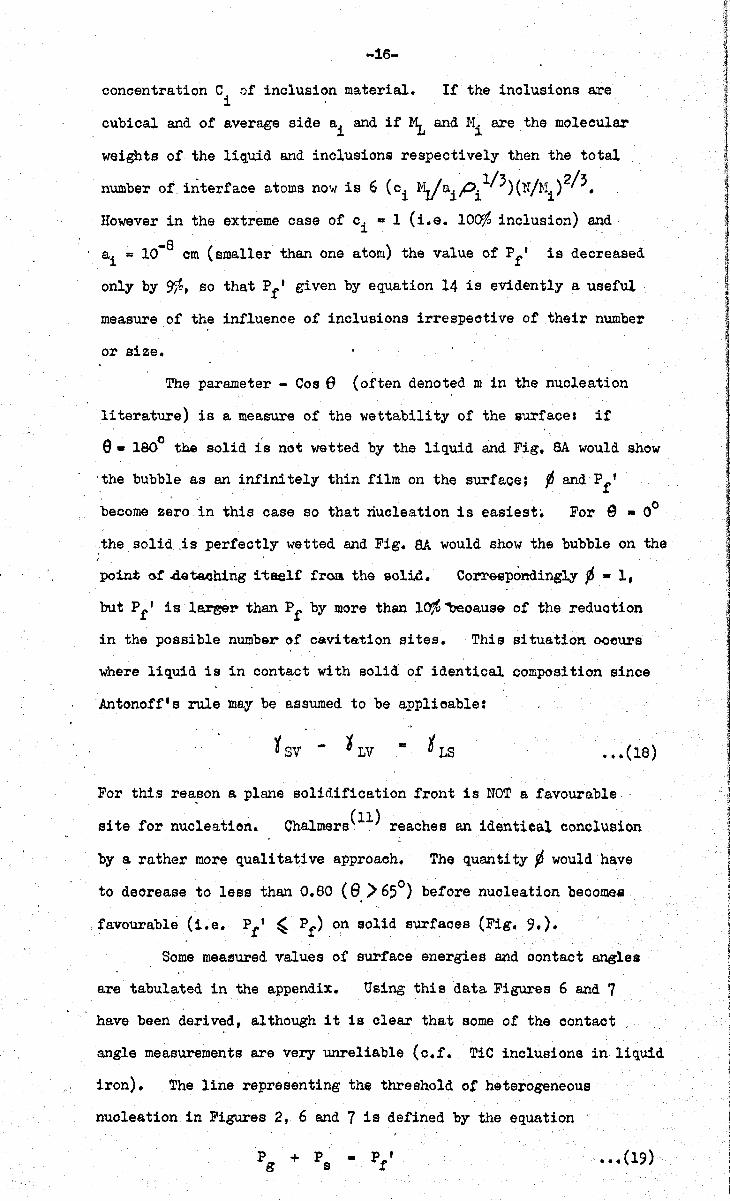
The parameter - Cos e (often denoted m in the nucleation
literature) is a measure of the wettability of the surface: if . , . 0 . e • 180 the solid is not wetted by the liquid and Fig. SA would show
·the bubble as an. infini tely thin film on the surface; ~ and P f'
become zero in this case so that nucleation is easiest. For e _ 00
,the solid. Js perfectly wetted and Fig. SA would show the bubble on the
point G! 4e'ta.tJhing itself frca the solid. Corr&SPondingly ¢ - I,
but P f I is la.rser than P f by more than l~ ~oause of the reduotion
in the possible number of cavitation sites. This situation ooeurs
where liquid is in contact with solid of identical composition since
Antonotf's rule ~ay be assumed to be applioable:
••• (18)
For this rea,son a plane solidification front is nOT a favourable (11) .
site for nucleation. Chalmers reaches an identical conclusion
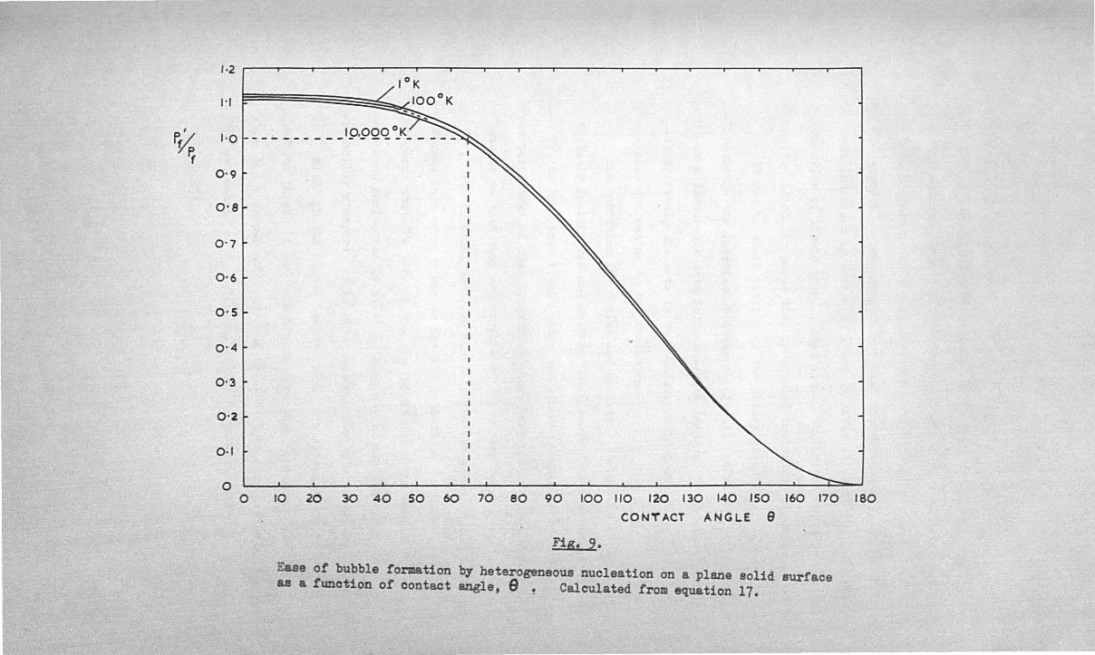
by a rather more qualitative approach. The quantity p would have
to decrease to less than 0.80 (9,)650) before nucleation becomes
favourable (i.e. Pf ' ~ Pr) on solid surfaoes (Fig. 9.).
Some measured values of surface energies and oontaot angles
are tabulated in the appendix. Using this data Figures 6 and 7
have been derived, although it is olear that someol the oontaot
angle measurements are very unreliable (c.r. TiC inclusions in liquid
iron). The line representing the threshold of heterogeneous
nuoleation in Figures 2, 6 and 7 is defined by the equation
p + P - Pr' g s ••• (19)

,
.' . • " .0 • •
~. , .
.. - _ .. I
, " " ,; ..... -- .-
FiB. 8.
I
I
LIQUID
SOLID
Heterogeneous nuoleation at various interfaoes.
(A)
(9)
(c)
(D)
H<;>'~! ? . . . . . . . ". '. . . '. . . ..... . .' .'. : .' .. ---, . ....,.,.:.,...:.,.....,. .. .. . ..' .' '. ... ~ '.. . . .. : .". . .. .. ..
.. .... . . . . . . " ..
. ..... ..
.. .. .. ., ......
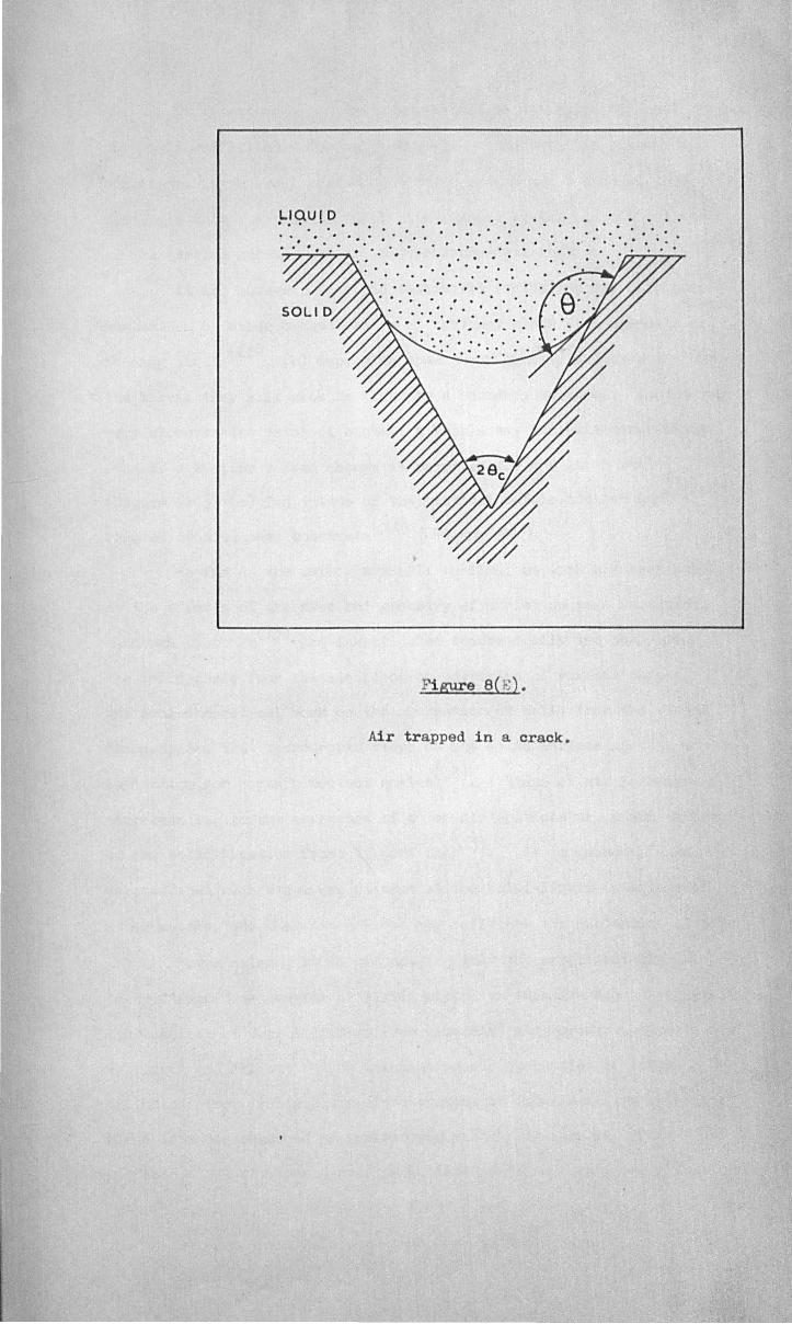
Figure 8(1;.: ).
Air trapped in a oraok.
, '.. . . . . '. "." . . . ..
-17-
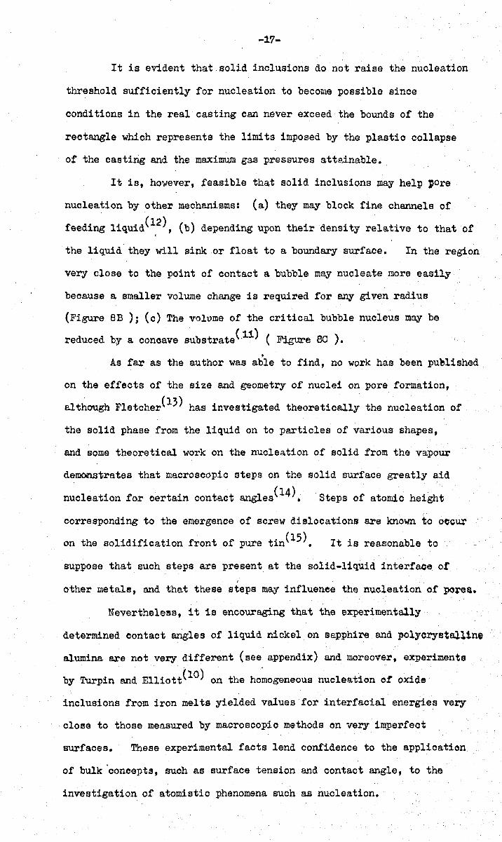
It is evident that solid inclusions do not raise the nucleation
threshold sufficiently for nucleation to become possible since
conditions in the real casting can never exceed the bounds of the
rectangle which represents the limits imposed by the plastio collapse
of the casting and the maximum gas pressures attainable.
It is, however, feasible that solid inclusions may help pore
nucleation by other mechanisms: (a) they may block fine channels of
feeding liquid(~2), (b) depending upon their density relative to that of
the liquid they will sink or float to a boundary surface. In the region
very close to the point of contact a bubble may nucleate more easily
beoause a smaller volume change is required for any given radius
(Figure 8B ); (0) The volvme of the critical bubble nucleus m~ be
reduced by a conoave substrate(·11) ( Figure eo ) • •
As far as the author was able to find, no work has been puelished
on the effects of the size and geometry of nuclei on pore formation,
although Fletcher(13) has investigated theoretically the nucleation of
the solid phase from the liquid on to particles of various shapes,
and some theoretical work on the nucleation of solid from the vapour
demonstrates that macroscopic steps on the solid surface greatly aid
nucleation for oertain contact angles(14). Steps of atomio height
corresponding to the emergence of screw dislocations are known to occur
on the solidification front of pure tin(15). It is reasonable to
suppose that such steps are present at the solid-liquid interface ot /
other metals, and that these steps may influence the nucleation of pore~.
Nevertheless, it is encouraging that the experimentally
determined contact angles of liquid nickel on sapphire and polyorystal11ne
alumina are not very different (see appendix) and moreover, experiments
by Turpin and Elliott(lO) on the homogeneous nucleation ot oxide
inclusions from iron melts yielded values for interfacial energies very
close to those measured by macroscopic methods on very imperfect
surfaces. These experimental facts lend confidence to the applioation
of bulk concepts, Bucll as surface tension and contact angle, to the
investigation of atomistic phenomena such as nucleation.
P~ r,
'·2
1'1
1'0
0'9
0'8
0'7
0'6
0'5
0'4
0'3
0'2
0·1
0 0
10,000 oK -------------------
-I
10 20 30 40 SO 60 70 80 90 100 110 120 130 140 ISO 160 170 180
CONTACT ANGLE 9
Fig. 9.
Ease of bubble formation by heterogeneous nucleation on a plane solid surface as a t'unction of contact angle, 9! Calculated from equation 17.
-18-
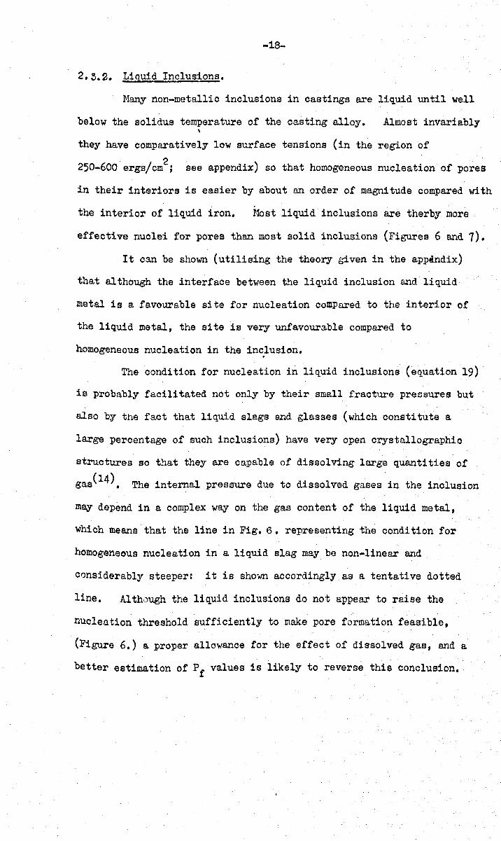
2.5.2. Liquid Inclusions.
Many non-metallic inclusions in castings are liquid until well
below the solidus temperature of the casting alloy. Almost invariably \
they have comparatively low surface tensions (in the region of
250-600 ergs/cm2; see appendix) so that homogeneous nucleation of pores
in their interiors is easier by about an order of magnitude compared with
the interior of liquid iron. Uost liquid inclusions are therby more
effective nuclei for pores than most solid inclusions (Figures 6 and 7).
It can be shown (utilising the theory g2ven in the appindix)
that although the interface between the liquid inclusion and liquid
metal is a favourable site for nucleation comPared to the interior of
the liquid metal, the site is very unfavourable compared to
homogeneous nucleation in the in~lusion.
The condition for nucleation in liquid inclusions (equation 19)
is probably facilitated not only by their small fracture pressures but
also by the fact that liquid slags and glasses (which constitute a
large percentage of such inclusions) have very open crystallographic
structures so that they are capable of dissolving large quantities of
gas(14). The internal pressure due to dissolved gases in the inclusion
m~ depend in a complex way on the gas content of the liquid metal,
which means that the line in Fig. 6. representing the condition for
homogeneous nucleation in a liquid slag may be non-linear and
considerably steeper: it is shown accordingly as a tentative dotted
line. Although the liquid inclusions do not appear to raise the
nucleation threshold suffiCiently to make pore formation feaSible,
(Figure 6.) a proper allowance for the effect of dissolved gas, and a
better estimation of Pf values 1s likely to reverse this conclusion.

-19-
2.3. 2 Complex Inclu~~.
Complex inclusions areCOmL~on in castings of nearly every type:
In iron and steel, solid alumina-type particles are often contained
in a liquid sulphide or silioate matrix (although the soa11 contaot
angles of the latter make decohesion unfavourable at this boundary).
In cast iron, graphite (which appears to make high eontact angles with
most inorganic liquids) is often ~ljaoent to low melting point
sulphides and phosphides.
Employing equation (lOa) to determine the fracture pressure of
the liquid phase of the inolusion, and then reducing this value by
applying equation (17) then it is possible to obtain very low fracture
pressures. Assuming a surface energy for the liquid of 250 dynes/cm2,
~ and very poor wetting of the solid phase (e C:! 1600
), then decohesion •
at the solid-liquid interface occurs at about -200 atmospheres.
This is more than an order of magnitude lower than fracture pressures
obtainable with single phase inclusions, and may be relatively easily
attained by either gas or shrinkage in relative isolation or in
combination.
Immiscible liquids are quite common in complex inclusions and
the author has extended Fisher's analysis to determine fractUre
pressures for the liquid-liquid boundary (see appendix)~ It is to
be regretted however that very little data is currently available on
interfacial energies between non-metallic liquids at such high
temperatures, (134, 135 ) although measurements of contact angles and
interfacial energies between liquid iron and various slags are
reasonably plentiful.(166-175)
*neference 181 gives some evidence that 1600
may be a ma.x:i1l'lUIn possible
contact e.1" .. gle for aJ.ly liquid .011 a solid.
-20-
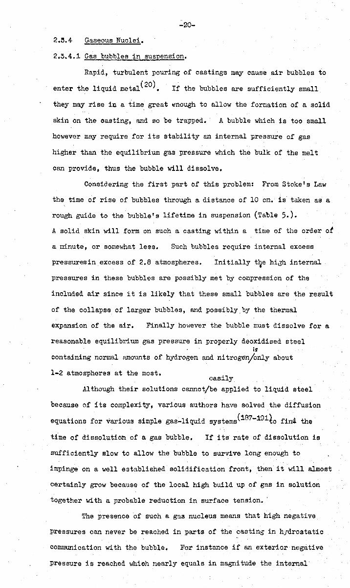
2.:5.4- Gaseous Nuclei.
2.3.4.1 Gas bubbles in suspension.
Rapid, turbulent pouring of castings m~ cause air bubbles to
enter the liquid metal(20). If the bubbles are sufficiently small
they may rise in a time great ~nough to allow the formation of a solid
skin on the oasting, and so be trapped. A bubble which is too small
however may require for its stability an internal pressure of gas
higher than the equilibrium gas pressure which the bulk of the melt
can provide, thus the bubble will dissolve.
Considering the first part of this problem: From Stoke's Law
the time of rise of bubbles through a distance of 10 cm. is taken as a
rough guide to the bubble's lifetime in suspension (Table 5.).
A solid skin will form on such a casting within a time of the order of
a minute, or somewhat less. Such bubbles require internal excess
pressures in excess of 2.8 atmospheres. Initially t~e hiJh internal
pressures in these bubbles are possibly met by compression of the
included air since it is likely that these small bubbles are the result
of the collapse of larger bubbles, and possibly.by the thermal
expansion of the air. Finally however the bubble must dissolve for a
reasonable equilibrium gas pressure in properly deoxidised steel is
containing normal amounts of hydrogen and nitroge~only about
1-2 atmospheres at the most. easily
Although their solutions cannot/be applied to liquid steel
because of its complexit,y, various authors have solved the diffusion
equations for various simple gas-liquid systems(187-191io finQ the
time of diss.olution of a gas bubble. If its rate of dissolution is
sufficiently slow to allow the bubble to survive long enough to
impinge on a well established solidification front, then it will almost
certainly grow because of the local high build up of gas in solution
together with a probable reduction in surface tension •.
The presence of such a gas nucleus means that high negative
pressures can never be reached in parts of the casting in hydrostatic
communication with the bubble. For instance if an exterior negative
pressure is reached which nearly equals in magnitude the internal
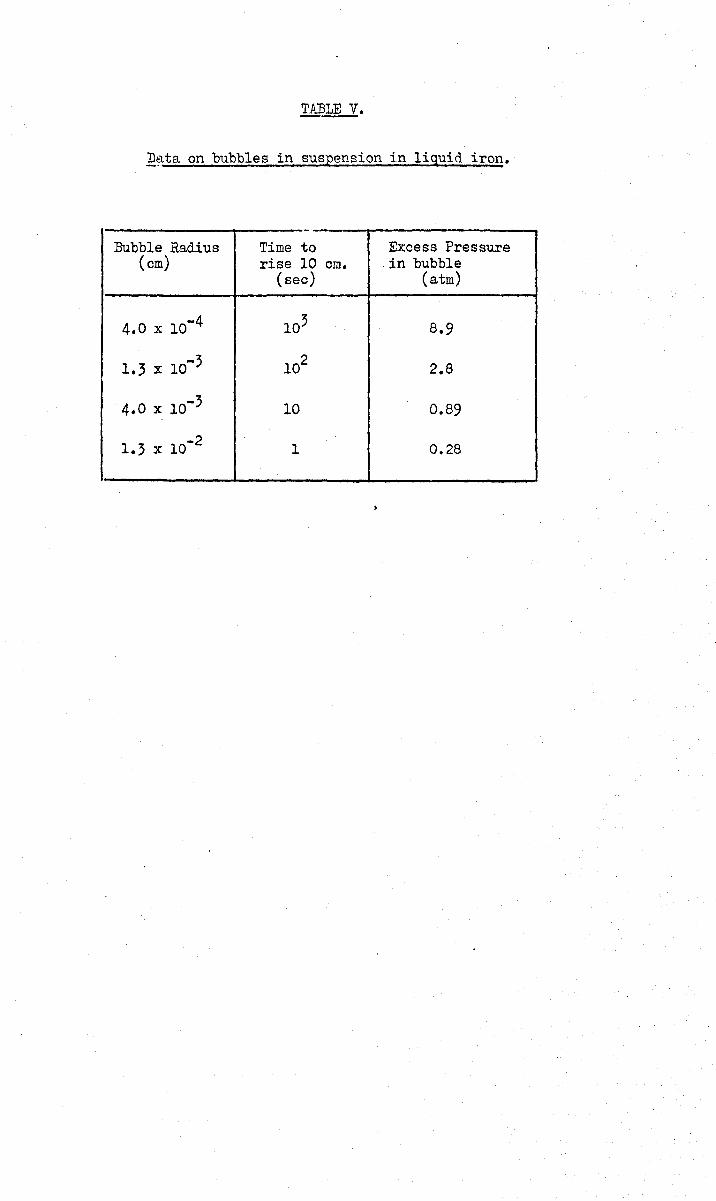
~ata on bubbles in suspension in liquid iron.
,-Bubble Radius Time to Excess Pressure
(em) rise 10 em. in bubble (sec) (atm)
4.0 x 10⁻⁴ 103 8.9
1.3 x 10⁻³ 102 2.8
4.0 x 10⁻³ 10 0.89
1.3 x 10 -2 1 0.28
-21-
gas pressure (3 atm. for a bubble lfA radius) then the bubble will
expand to macroscopic size, relieving the external pressure (equation 1.).
Thus, as Blake points out(8), the tensile strength of a liquid body is
in practiee determined by the size of the largest gas bubble present.
In conclusion, although the possibility of such nuclei cannot be
ruled out, the required and possible lifetimes are shown to be nearly
mutually exclusive, so they constitute an unlikely source of porosity.
It may be noted that such nuclei may be avoided by the use of suitably
careful casting technique~ or by casting in vacuum.
-22-
2.~.4.2 Gas-filled Crevices in Solids.
The vapour bubbles produced by boiling water in a glass container
can be seen to be nucleating from distinct points which could be pockets
of gas contained within small crevices in the wall of the container.
Nuclei of a similar nature are thought to be responsible for the 'boil'
(21-23) in an open hearth furnace •
In a casting, however, the boundary of the liquid metal at some
stage during solidification is not analogous to the inner surface of
the glass container, nor to the bath of the open hearth, which were both
previously in contact with the air before receiving the liquid cover.
The boundary of the liquid surface in a solidifying casting is formed
by a phase transformation, and because of this, perfect atomic contact
wou1J be expected at every point. • The same applies for indigenous
inclusions (1.e. formed in the melt). Gernez(24) demonstrates that
crystalline solids formed in the liquid and which had never been in
contaot ~th a gas were incapable of inducing effervescence in the
liquid which was supersaturated with gas (to a pressure however of
probably only about an atmosphere).
Thus in a casting, porous inclusions containing gas can only
have an exogenous origin (i.e. were washed in from the tip of the ladle,
or from the mould wall etc.).
Harvey(25) describes a stabilising mechanism which relies on the
fact that a bubble which has a lower internal pressure than that of
the surrounding liquid can be in equilibrium wi th the liquid proviciing
it has a concave surface (Fig. 8E).
the fracture pressure
'P , f
Their theory leads to a value of
where P is the maximum pressure to which the melt has been subjected, m
P g is the equilibrium gas pressure in the bubble, and Al and A2 are
constants depending upon the angle of the crack and the advancing .
and receding contact angles, e a and e . r
approximately equal, then ~ becomes unity,
If ea and 9r
are
A2 becomes zero. and
since P is usually one atmosphere an unstable expansion of the nucleus m
-25-
occurs when a shrinkage pressure of about -1 atm. is reached
(i.e. about zero absolute pressure).
It is clearly not helpful to discuss such gas-filled crevices
in any more detail since any number of zeomctries can be envisaged:
Blake (3) suggests a type which becomes narrm-lcr towards its mouth, as
a narrow··necked bottle, and thus enclosing gas irrespective of contact
angle criteria.
The Bro,,,th and emergence of gas bubbles from crevices is
described theoretically in some detail by Va1Iet(2l) in relation to the
carbon 'boil' during steelmaking, and investi~ated experimentally with
d h . 1· ·d b • • (182-187) 'iater an ot or organ1.C l.qU1.S y many l.nvest1.r.ators -
particularly with a view to understandin~ heat transfer in boilers.

-24-
2.4 NUCLEATIOn BY ATOMIC COLLISIONS.
In their various theoretical models of liQuids, the investieators
of fracture pressures failed to include the presence of occasional fast
movinep high energy particles from space (Cosmic'Rays) and the relatively
high density of enereetic alpha particles due to the decay of trnces of
radioactive matter which are prevalent everywhere. Althoup,h no direct
evidence exists to determine whether such phenomena do in fact
influence pore formation in liquid metals, the purpose of this section is
to assess this possibility as far as possible by inference from other data.
In 1953 Glaser first demonstrated that fast moving ~tomic particles
can cause the nucleation of bubbles in metastable liquids(27). This
observation has been put to widespread practical use in the construction
of bubble chambers \vhich illustrate the track of n particle through •
the liquid by corresponding trail of bubbles. ~1ost chamhers
utilise superheated liquids, although some(2B) employ a liquid super-
saturated l1ith gas under pressurc:, '>1hich is closely an31op;ous to the
conditions in a solidifying castinp.. Hore recently, several
investigators have measured the effect of various radiations on the
f f I , ., (29 ,,31) h' h h ' b racture pressures 0 lqUl(,9 W lC are s own ln some cases to e
very much reduced. These studies have been so far only directed at
t ' I' 'd d f h I' 'd h v d fmo (35) wa er, organic lqul s, an a ew eavy lqUl 9 suc as .. e an .il: 6 •
Early theories(29) assumed that in a collision of the energetic
particle with an atom in the liquid, the charge associated with the
particle uould be redistributed over the surface of nn embryonic
bubble. The effect of the mutual repulsion of the charge would act
in opposition to the surface tension and thus aid nucleati·:ln. If this
were true then the possibility of bubble formation by this mechanism
in liquid metals would appear to be remote because of their high
conductivity. However, more recent thcories(33,3!+) which have had
a fair Tlleasure of experimental success, indicate that nucleation occurs
by the deposition of very localised quantities of energy by a direct
knock-on of the incident particle with an atom in the liquid, causing
a small region to become vapourised.
-25-
Thus a close analogy can be drmVI1 \.;rith the production of
radiation damaee in solid metals~ where it is now well established (37)
that an incident particle of sufficient energy will produce intense
vibration in the region surrounding its encounter with a lattice atom.
The region finally cools to contain a hi!,?'h density of vacancies.
It seems reasonable to conclude therefore that a similar event
in a metallic liquid yill produce a vapour bubble exceedine the size
of the critic~l bubble required by classical nucleation theorYt so
that P f ~1ill be 1m·1ered.
He nO\1 turn to a consideration of the possible sources of
suitable radiation.
-26-
2.4-.1 Cosmic Ray-!.
Sette and tJ.:mderlinr'h (32) have shown that tha cavitation threshold
for water subjected to ultrasonic vibration is affected in a complex
but reproducible ""ay by the thickness of a lead box '''hich encloses the
apparatus. The results are explained in terms of cosmic rays
intercepting the lead shield and giving rise to secondary particles which
may also cause nucleation events in the metastable liquid.
Nevertheless, as a prolific source of bubble initiation, which
seems to be required to explain porosity inreal castin~s, cosmic rays
may be rather unlikely for several reasons~
(i) The frequency of arrival of cosmic rays(36) is only about ?
one particle Iminute lcm"" , so that relatively fC,"1 particles ,,,,ill enter a
normal sized casting durin?: the critical final stap,es of solidification~
when gas and shrinkarc pressures are risin3 more rapidly.
(ii) At ground level only appr0xinately 30 per cent of the total
incident radiation :a:~ Brouml loa,,,! consists of the strongly interactinr:
'soft' variety~ thus most particles uill pass harmlessly straight
through a casting.
(iii) At a late stDge in solidification (i.e. uhen the fraction
of liquid prescnt is small) it is unlikely that a primary (or secondary)
collision '("ithin the castin~ will be uithin the highly strained
residual liquid.
(iv) In order for nucleation by cosmic rays to be favourable, Pf
must be lowered by at least one or two orders of mnrnitude since the
collision site will not in general be adjacent to n solidification front
where conditions of high ras content an~. louer surface tension prevail,
nor at interfaces within complex inclusions, ~1here decohesion is
relatively easy.
The possibility of bubble nucleation by cosmic rays is by no
means ruled out in lar~e castings, since slower freezin~ means that
more time is available for a favourable collision to occur, and the
area and depth of the casting also increase t~is possibility.
Furthermore, of course. only one such event is necessary to initiate
porosity which may branch and spread throughout a casting.

-27-
2.4.2. RADIOACTDIE DECAY.
Small amounts of radioactive elements are present in most metals.
Investigators of radioactive phenomena (who may have to construct
apparatus and research rooms with a low radiation background) have
difficulty in obtaining materials with suffioiently small amounts of such
impurities and often utilise steel from dismantled battleships since
this is known to be low in active contaminants. Modern steels are
relatively highly contaminated as a result of the fall-out from
atomic explosions, and perhaps occasionally from the increasing amounts
of radioactive waste from industrial, medical and nuclear pO'.ver sources.
The decay of an atomic nucleus may result in the release of one
or more alpha or beta particles. The latter are electrons which are
too small in mass to cause any important damage from the viewpoint of
the nucleation of pores. Electron bombardment of solid metals is
known to produce only occasional single ate'mie displacements in the
lattice (37) •
In contrast, alpha partioles are heavy and have high energy,
resulting in severe local damage to the lattice of solid metals(37),
and thus probably resulting in vapour bubbles in liquid metals.
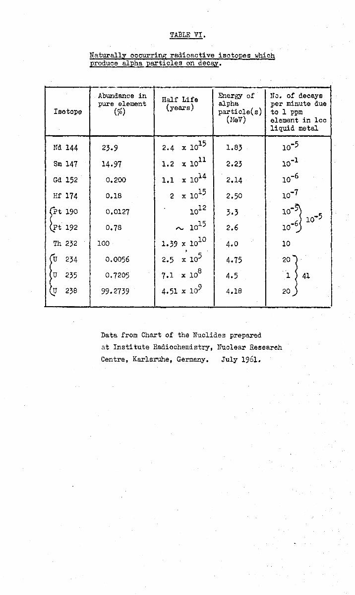
Table 6. gives a list cf naturally occurring radioactive isotopes
which produce alpha particles on decay. The number of decays per
minute varies directly as the fraction of the isotope present in the
element, and inversely as the length of the half-life. Only Th and U
are seen to produce a significant number of decays per minute, although
it is quite feasible that some artificially produced isotope may have
found its way into the metal; for instance 1 p.p.m. of Ra 226 or
Pa 231 in 1 cc. of metal will produce 108 and 107 decaYS/minute
respectively. There are several dozen artificial isotopes which
are alpha-emitters.
Bubble nucleation by fission fragments from the spontaneous
disintegration of an unstable nucleus such as U may ordinarily.be, 1·l.~.el.o:1ablc
discounted (except for the casting of pure uranium or similar/material)
because such events are many orders of magnitude more rare than
alpha-deoays.
Isotope
Nd 144
Sm 147
Gd 152
Hf 174 tt 190
Pt 192
Th 232
I""u 234
u 235
u 238
TABLE VI.
Naturally occurring radioactive isotopes which produce alph_Ei. particles on deca.y.
I t
--_., --Abundance in Half Life Energy of no. of decays pure element (years) alpha per minute due
(%) partic1e(s) to 1 ppm (NeV) element in lee
liquid metal
23.9 2.4 x 10¹⁵ 1.83 10-5
14.97 1.2 x 10¹¹ 2.23 10-1
0.200 1.1 x 10¹⁴ 2.14 10.6
0.18 2 x 10¹⁵ 2.50 10.7
0.0127 1012 3.3 10-~ 10-5
0.78 "-' 1015 2.6 10.6
100 1.39 x 10¹⁰ 4.0 10
• 0.0056 2.5 x 10⁵ 4.75 20 ...
0~7205 7.1 x 10⁸ 4.5 1 41
99.2739 4.51 x 10⁹ 4.18 20 .....
Data from Chart of the Nuclides prepared
at Institute Radiochemistry, Nuolear Researeh
Centre, Karlsruhe, Germany. July 1961.
-28-
Several factors favour the creation of pores by the dec~ of
radioactive contaminants rather than by cosmic radiation: 1) The
radi~tion is 'in situ', and thus exactly where it is required to
create pores - there is no problem of the radiation having to penetrate
just the correct distanoe into the casting. 2) Alpha particles are
strongly interacting and will in general not escape from the casting
so that the process operates at maximum efficiency. 3) Given a
favo~ab1e partition coefficient the contaminants lj,ri11 be ooncentrated,
together with other impurities, into the centre of the oasting where
both gas and shrinkage will both aid nucleation to the greatest
advantage. 4) The frequency of cosmic rays is very constant(36)
although it is the experience of foundries t!lat porosity 'comes and
goes' for no apparent reason. The blame is sometimes traced to
gases in solution and other causes: but an additional reason may well
be the wide and erratic variation in radioaotive contamination from
one batch of metal to another.
-29-
2.5. RTI'LATION BETWEEN SIDUNKAGE A.1fD GAS PRESSURES IN VAHIOUS CASTINGS.
From elementary considerations, omitting several important f~ctors
discussed in Section 1., Flemings and co-workers(38) deduce an
expression for the equilibri~11 pressure of a diatomic gas in solution in
the residual liquid of a casting
P g
•.• (20)
where C is the original gas concentration at the start of solidification, o
fL is the fraction of liquid at some later instant, KL and Ks ar e the
solubility constants for the gas in the liquid and solid mQtal ~BPQCtively.
For a cylindrical casting of a mushy freezing alloy these authors derive
from geometry
'2 11 a n-r:.7 ... (21)
where n is the number of feeding channels per square centimetre of cross
section, (a) is the mean radius of the channels, and 1:0 is tortu~si ty
factor associated with the non-linearity of the channels. Also
••• (22)
~lhere B is a function of the size of the casting, the dendrite' arm
spacing, and the thermal properties of the metal and mould. Thus
eliminating (a) from equations (20) and (22) we obtain the locus of
the line AB (Fig, 2.):
P = Co2/ [Trn1:.(K _ K )(B!P )t .. K ]2 g / dL s s s ••• (23)
Similar relations may be obtained from the work of these authors
for the cases of unidirectional dendritic solidification, for cellular
solidification, and for the case of a cylindrical casting in a skin
freezing metal.
Considering n6¥.' the aituation in which a volume of liquid is
isolated from supplies of feeding liquid, the pressure in this confined
liquid volume is(39)
= 2 Y LS/a - 2Y In (b/a) ••• (24)
-50-
assuming for simplicity that Po and Pd are negligible and that the
whole castine is in a plastic condition. ¥ LS is the energy of the
liquid-solid boundary, Y is the yield strength of the metal at that
temperatvxe and strain rate, a is now the radius of the liquid core
b is the distance from the centre of the confined liquid to the
nearest free surface of the casting. From geometry (assuming
approximately spherical symmetry)
••• (25)
substituting (25) into (20) rund eliminating (a) from the resulting
equation and (24) will give the relation between Pe and Pg for
a region of confined liquid in a casting.

2.6. Crcwth of Pores.
2.6.1. Kinetics.
Once nucleation of a pore ~as occurred at B (Fig. 2.)
the strain encr~' in the liquiG and surroundin~ solid is
surldcnly relea:.cd by the expansion of the pore anc the ;?ressure
in thz liquid jumps to point C.
A ' .. 'I f '11 I'd' .. ' , b T\ ' (nO) ,~ Clne"rl !n 0 cutectlc a oy so 1 l!lcatlon y !.,aV1S
shmvs that pores sl'rin~ to equilibriun size in a time shorter
than the shutter speed of the ca~era (about 1/24th second)
and t~lercafter p,rml only a little at a very sloH rate until
solidification is complete. Experiments involvin~ ultrasonic
cavitation in liquids indicate that this rapid p,rowth period
occupi~s less than 1 millisecond(?13), ar.d calculations
involvinp inertial forces in the li,!uid su~eest that the
period is nearer 1 rdcroscconc (211) ~ althou~h if heat transfer
consi<.~crations arc included in the calculation (212) then ~rowth
tines a?,ain become of the order of milliseconds. t~~
intercstine rheolo~ical apprcac~l to this problem is outlined
b ·, ff d 'f (217). . , t' , y l~O nan an ,; .. yers ln an lnVGstlf~. loa lutO
cavitation dynamics in thin liquid filrr.o.
Som:.:! quite relevant expcrir.:!l1te.l studies on th(;l
erm17t!1 rates of bu~bl..;s i.n boili!:.? liq'.lit1.:3 may bc referred
(207'·209) to •
Follm'lin,~ the ideas of Phittcnber~cr and ?11incs (2) ~
further nucleation in this body of liquid is impossible
because hydrostatic tension c.~nnot c'~vclo? so lon~ as s!lrinknec
is bcin~ accomI!l.odatoc1 by r:roHth of the cxistin~ pore. As
freezin,~ pror,resses hO~Jever ~ the p'as concentraticn in the
resiclual liquid uill increase, shiftin~ its pressure-
concentration state to the ripht of Fi~. 4. Point D may
never be reached ~ hOlrlCvcr» if the availab 1e ~as has
sufficient timc to diffuse to th~ existine porc, or if
· ~32-
solidification overtakes the region first. Uevertheless, if
parts of the liquid in hydrostatic cOmr.lunication with the pore
are sufficiently distnnt so th~t their eas content is not
drained by tbe ~rowin~ pore, but allm.Jcc! to increase? then D
may be reached so teat more pores ~dl1 fom.
After the first rapid stage of grm'lth tl~O extreme
medes of ~ro\;rth may be distinguished' (a) when the pore is in
perfect communication: with feedinJ?: liquic. its rate of groHth
is determined by the rate of gas deposition alone, and
(b) when liquid feedine is cut off (and llhen pores have already
been nucleated) then in the absence of gas the total volume
of pores that llill develop must equal the shrinka~e of the
body of isolated liquid.
(;ro\>lth by eas precipitetion may b~ limited either by
the rate of diffudon of eas throu,9:h t~lC liquid ph:lse, or by
the rate of diffusion across the bubble interface, whichever
may be the slower. Either process is complicated (a) by t~e
increase in surface area of the cavity, 't.Jhich, because of the
complexities of pore shape, n2ec not be simply related to the
quantity cf e.as releasec. (b) by the irreeularly changing
ratio of gas -liquid to gas"-solid surfac(l: (c) by the nOto1
and possible turbulence of the ~as'-solvent liquid as the pore
grows; and (d) by the chan~es in solubility and diffusibn
coefficients with alterntions in temperature and composition.
Rence it is not to be expected that the rate of pore gro\·rth
by gas rejection will follow any simple lm~.
(187-192) Nevertheless several authors have nttempted
to analyse the gro\lth of zas bubbles in a liquid, making
the great simplification of assumin~ a spherical bubble
at rest in an infinite liquid.
Shrinka~e-controlled cavity ~rowth is probably more
susceptible to analysis since it must proceed in direct
·,33-
proportion to the quantity of heat extracted froM t~.e body of
confined liquic.. Ruddle (214) has' provided an exhaustive
critical analysis of !)uc'h heat flOtl solutions for castings.
2.(.2. Final Size of Pore.
The single cavity formed at B (Fi~. 2.) has a growth
advantaf:G over th~ c<'lvities which stnrt their grm-1th later
at D; the sin8le pore is initially larZer than the later pores
because of the lonzer time and the stored elastic enerqy
available for its gro"lth~ and thereby also grows at a faster
rate because of its ereater surface area availcble for
gas transfer.
Grmlth is arrested by local cOMpletion ef frcczin~.
In principle it will never be stopped by completion of 8as
precir:itation since an infinite til!lo is rer:;,uired to bring a
diffusion process to equilibrium. Accordingly, it is
expected that pores will be lar~er the loneer the timo
allO\Jcd for their grm·7th.
Easy-nucleation neansthat very little plastic
collapse of the castin~ \7i11 occur since the hydrostatic
tension will never reach hi~h v:llucs. Thus the resultin~
porosity will be a mnxi~um i.e. numerically equal to the
solidification contraction - of the order of 3% •• or possibly
hirher with the assistance of ~as. In the case of difficult
nucleation (hi?,h Pf ' values) pore nucloation is delayed until
the shrinka3e pressure reaches the necessary hieh value to
satisfy the nucleation condition. This means therefore thnt
the final pore ~lil1 be small b::;cause of the prior
occurrence of a. considerable anount of s.,lid foeding.
The final size of a pore in the fully solidified
casting may be influenced soncwhat by viscous or plastic flov
in the manner of sinterinp,. A survey ?f sinterin~ mechanisms
lOs 0 b n __ 0 (215) 1 h h f h t ~lven y .'.\.d1~lqvlSt a t .oup; or sue. processes 0

become properly effective (since sinterinz normally occurs
under initia.lly stress-free conditions) t~le hieh internal
gas pressure or surroundina: hydrostatic tension which in
the first place both contributed to the crcatio:l and
grO\vth of tho pore ~ and \.;hich nO't;' ipso facto oppose its
collapsc) must therefore first b~ dissipated before
sintering can take place.
Thc shape of a pore will also be modified to some
extent by diffusion in the solid statc(216).
-35-
3. FEEDING UECH.ANISHS.
There appear to be tIt 1eaat 5 mcchaniams by \"hich the
difference in volume between the liquid and solid states can be
acconnnodatcd in a solidifying castin8) hOl<1CVer not all of the
mechanisms need operate in any single ccse. Adequate
feeding of anyone of these means relieves the hydrostatic
tension in the reoaining 1iquid~ end 30 reduces the
possibility of the nucleation and the subsequent enlargement
of a pore. 'rhe feeding processes are dealt with in the order
in which they occur during freezing, ~nd this order
coincides with a progressive transition from what night . usefully be termed 'open' to 'closed' feeding systems.
3.1. Liquid Feeding.
Liquid feeding is the most 'open'feeding mechanism
and generally precedes other forms of feeding (Fig. 10.)
although in skin freezing metals and eutectic3 it is normally
the only method of feeding.). It has been much investigated
both theoretically and experimentally and for this reaSon is
probably the best understood of all the types of feeding.
H.:lllace(227) gives a comprehensive rcvim., up to 1959.
Inadequate liquid feed in?; leads to form.:ltion of
porosity by the elementary non-nucleation process by the
spr~ad of the primary shrinkage pipe into more distant regions
of the casting. (Section 2.1.).
3.2. Hass Feeding.
[This is a term coined by Baker(223) to denote the
consolidation of a fluid mass of solid crystals and residual
liquid.) \ The movement of this slurry is arrested when the
growing crystals impinge and interlock.,. Pellini (229) J
suggests that this occurs at a critical value of 60% solid
for steels~ Flemings et.a1. (230) infer from their experiments

SCHEMATIC REPRESENTATION OF
Liqui.d fud i"9
FEEDING MECHANISMS
FIG. 10 .
Mass fud 109
o r til
o
Interdendriti c + Intercellu lar feeding
~
• o 0 • •
some solidstate diffusion
*'---- ... ..
Burst (macro)
(elastic) (plastic) Solid feed I n9
fuding (micro)
final state of cast ing

--36-
on, the flow of liquid through a dendrite nesh that 'flo~v
channelling' through the mushy zone of Al-4.5%Cu alloys occurs
~t up to 68% solid. and the experi8ents by Singer end
Cottrell(231) on the mech3nicnl strengths o~ A1-Si alloys at
temperatures above the solic.us indic<J.tc that the nushy zone
gains nechanical strength at about 60% solid.
Many of the earlier authors suggest that r.H1SS feeding
is the important process fruM. the point of view of redud.ng
porosity. Such a view is largely unjustified because(thc
critical feeding stages occur sone time after mass feeding has
practically ceased~ However, consideration of this process
is warranted in order to sho\v how tho £10\1 of the liquid-
solid mass could indicate 'vhere blockages are likely to occur
with a given grain size in a casting of given geometry. Fer
instance the process tvould be expected to produce choking of
h l ' 'd 1.. 1 h ' ,(229) t h t e 1qU1 Cllanne at a c ange 1n sect10n , so tLlat t e
sections more distant from the feeder are less perfectly fed 1
and therefore, finally, possibly l~ss sound.
The proble8 is similar in some respects to that of
the flow of soils through various a~crtures, of which a useful
review exists by Brown(232), although the mechanics of soil
flow is still largely empirical and not well understood.
Furthermore the analogy is weak in two respects: (a) the
dendritic shape of sone metal crystals would cause premature
interlocking (nore anaL)gous to the flew of dendritic metal
pouders familiar in pm.,der netallurgy) and (b) the
considerable plasticity of the dendrites at the solidification
te1!lperatures which ~lould tend to act in opposition to a
premature interlocking effect.
An improvc1!lent and possible extension of this feeding
process by refining the grain size might, hmvover t impair
the subsequent interdcndritic feeding, although equation (28)
suggests otherwise. Nevertheless, this illustrates the
-37-
important point that a chanee in any particular casting
variabl~ mny affect various types of feeding in opposing
ll7aY5.
3.3. Jnterdendritic Feedinp..
1... Allen (1) in 1932 coined the tern ;'intcrdendritic
feedinb" to describe the £10\-1 of residual liquid (which was
compensating for the volumetric contraction i a, on solidification)
through the mushy zone of a casting) and made the first serious
attempt at a th~oretica1 analysis; if P is the pressure a
applied to the feeder head, &~d Pc th~ pressure at the tip of
an interdendritic channel. then th~ rate of flow alone the
channel is (P -p ) h.lL' \l7here l.l is the viscosity of the liquid a e
metal and L' a function of the length and dia~eter of the
channel (L' tends to increase as the channel narrmJS - which
could easily be demonstrated quantitatively if ~llen had
used thc \l7cll-known Poiseuille' s equation at this point).
Now if dm/dt is the rate of solidificntion the rate of
contraction ~17i11 be acm/ct so long as no pores form, so that
(P - P )/l.lL' = adm/dt a e
or
l.laL' dm/dt ••• (26)
As solidification proceeds the paths for the feed metal
become progressively constricted until the pressure P falls e
below a critical value at ,.,hich pores will nuclente.
Allen assumes that this critical value is the effective
, 1 '1 I ,(230) 'd h h l.nternal gns pr~ssure ~'hll. ~ F cmlngs conSl ers t at t e
value is zero.' Section 2. has shotm that both these
assumptions are incorrect in general, a1thoueh ~lemings
assumption will probably be justified if exogeneous inclusions
are present in the melt.
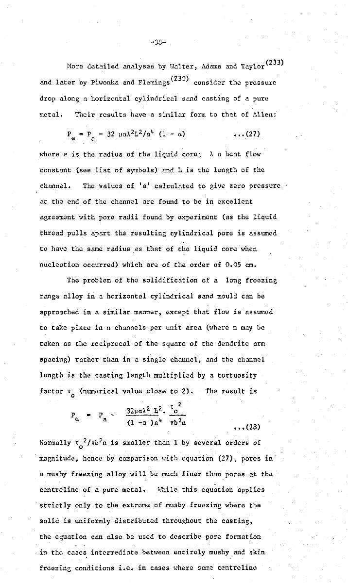
"38-
110re detailed analyses by till.lter, Adams and Taylor (233)
and later by Piwonka and Flemines(230) consider the pressure
drop along a horizontal cylindrical sand casting of a pure
metal. Their results have a similar form to that of Allen:
where a is the radius of the liquid core; A a heat flow
constant (see list of symbols) and L is the length of the
chmmel. The values of 'a' calculated to give zero pressure
at the end of the channel arc found to be in excellent
agreement with pore radii found by experiment (as the liquid
thread pulls apart the resulting cylindrical pore is assumed
to have the same radius as that of the liquid core when
nucleation occurred) which are of the order of 0.05 em.
The problem of the solidification of a long freezing
range alloy in a horizontal cylindrical sand mould can be
approached in a similar manner, except that flow is assumed
to take place in n channels per unit area (where n may be
taken as the reciprocal of the square of the dendrite nrm
spacing) rather than in a single channel, and the channel
length is the casting length multiplied by a tortuosity
factor T (nuoerical value close to 2). The result is 0
32lJClA 2 1;2. T 2
P P 0 .. -e a (1 -Cl )84 nb 2n
••• (28)
Normally T 2/nb2n is smaller than 1 by several orders of o
magnitude, hence by comparison with equation (27), pores in
a mushy freezing alloy will be much finer than pores at the
centreline of a pure metal. Hhilc this equation applies
strictly only to the extreme of mushy freezing where the
solid is uniformly distributed throughout the casting,
the equation can also be used to describe pore formation
in the cases intermediate between entirely mushy and skin.
freezing conditions i.e. in cases ~~here some centreline
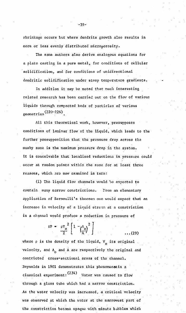
-39-
shrinkage occurs but where dendrite gro'''th also results in
more or less evenly distributed microporosity.
The same authors also derive analogous equations for
a plate casting in a pure metal, for conditions of cellular
solidification, and for conditions of unidirectional
dendritic solidification under steep temperature gradients.
In addition it may be noted that Buch interesting
related research has been carried out on the flow of various
liquids through compacted beds of particles of various
. (220~226) geometrlcS •
All this theoretical work, however, presupposes
conditions of laminar flow of the liquid~ t-lhich leads to the
further presupposition that the pressure drop across the
mushy zone is the maximum pressure drop in the system.
It is conceivable that localised reductions in pressure could
occur at random points within the zone for at least three
reasons, \.,hich are now examined in turn:
(i) The liquid flovY channels would be expected to
contain many narro~v constrictions. from an elementary
application of Bernoulli's theorem one 'Would expect that an
incrcaoe in velocity of a li~uid strean at a constriction
in a cr.anncl would produce a reduction in pressure of
••• (29)
where p is the density of the liquid, V its original o
velocity~ and A and A are respectively the original and o
contricted cross-sectional areas of the channel.
Reynolds in 1901 demonstrates this phcnomen~in a
1 . 1 . (234) t·T d fl c aSSlca experlment: vater was cause to ow
through a glass tube which had a narrO'>v constriction.
As the water velocity was increased~ a critical velocity
was observed at which the water at the narrowest part of
the constriction became opaque 'tIith minute b.1bbles which

-40-
extend sooe distance dO~l-stream. At the same instant a
loud hissing noise occurred which was assumed to be
associated with the collapse of the bubbles.
Equation (29) predicts rather lareer falls in pressure
than are to be expected in practice because of the neglect
of viscous drag from the m!lls of the channel which would
tend to favour the direction of liquid through casier
neighbouring channels.
(ii) Liddiard(235) suggested that the rapid accelaration
of residual liquid through the dendrite mesh as solidification
nears completion might create turbulent conditions. This
seems unlikely however in view of the wide applicability
of formulae, such as Poiseuille's, which are based on laminar
flow to the problem of liquid penetration through porous
d' (225-6) me 1a . •
(1.'].'].') Var].·ous authors(202,235) 1 d th t lave suppose a
vortices may occur during interdendritic feeding, and that
a bubble may nucleate at the centre of a vortex if the fall
in pressure at this point is sufficient.
predicted fall in pressure depends upon the particular
mathematical model chosen. Liddiard(235) and Dean(202)
both quote
6P = ••• (30)
where . r= the circulation (a measure of the intensity of
the vortex) p = density of the liquid: r = radius vector.
At the cent~e, therefore, the pressure difference falls
to minus infinity. This is only true for a 'free'
vortex, whose rotation is zero at the liquid boundary
and increases towards its centre.
A 'forced' vortex corresponds to a region of liquid
of radius R circulating with constant angular velocity ,~
(as a rigid disc). The pressure differential between
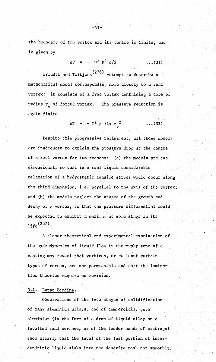
-41·-
the boundary of the vortex and its centre is finite, and
is given by
••• (31)
P d I d T oo (236) d °b ran t an eltJcns attempt to escrl e a
mathematical model corresponding more closely to a real
vortex: it consists of a free vortex containing a core of
radius r of forced vortex. v The pressure reduction is
again finite
AP = - r 2 p /4~ r 2 v
••• (32)
Despite thin progressive refinct!lent, all these models
arc inadequate to explain the pres~ure drop at the centre
of ,':1 real vortex for t~"o reasons: (a) the models are two
dimensional~ so that in a real liquid considerable
relaxation of a hydrostatic tensile stress would occur along
the third dimension, i.e. parallel to the axis of the vortex;
and (b) the models neglect the stages of the growth end
decay of a vortex, GO that the pressure differential would
be expected to exhibit a maximum at some stage in its
l 'f (237) 1 e •
A closer theoretical ane experimental examination of
the hydrodynnmics of liquid flow in the mushy zone of a
casting may reveal thct vortices, or at least certain
types of vortex, are not permissible cnd t!'Hlt the l.:uninar
flow theories require no revision.
3.4. Burst Feeding.
Observations of the late stages of solidification
of many aluminium alloys, and of commercially pure
aluminium (in the form of a drop of liquid alloy on a
levelled sand surface, or of the feeder heads of castings)
sho\<1 clearly that the level of the last portion of inter-
dendritic liquid oinks into the dendrite mesh not smoothly,
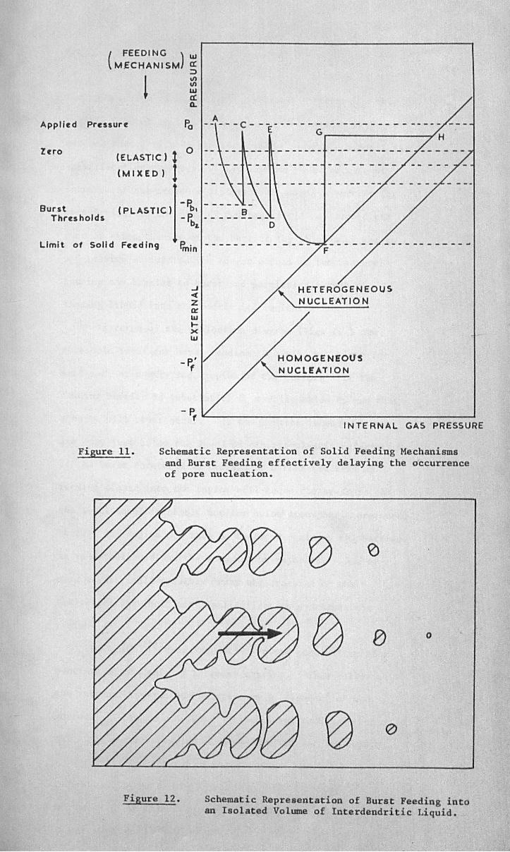
( FEEDING ) IIJ MECHANI SM a:
::::>
1 III III IIJ a: Q..
Applied Pressure Po
Zero
Burst Thresholds
(ELASTIC) 1 0
(MIXED) 1 -P.
(PLASTIC) -r.' _____ ~ __ _ bL 0
-------- - ----
Limit 01 Solid Fuding e· ----------min
Figure 11.
.J ~ Z ~ UJ )0-X IIJ
- P.' f " HOMOGENEOllS
NUCLEATION
- Pf
IIC.-___________________ --'
INTERNAL GAS PRESSURE
Schematic Representation of Solid Feeding Mechanisms and Burst Feeding effectively delaying the occurrence of pore nucleation.
o
Figure 12. Schematic Representation of Burst Feeding into an Isolated Volume of Interdendritic Liquid.
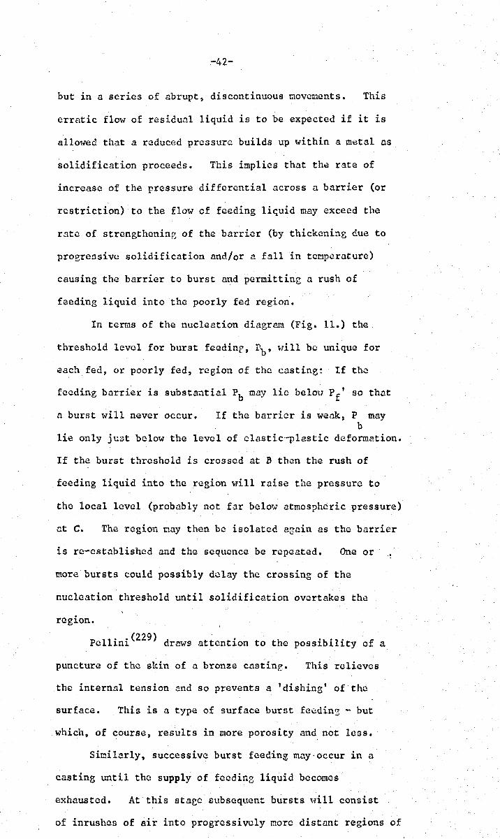
-42-
but in a series of abrupt, discontinuous movements. This
erratic flow of residual liquid is to be expected if it is
allowed that a reduced prc3surc builds up within a metal as
solidification proceees. This implies that the rate of
increase of the pressure differential across a barrier (or
restriction) to the flow of feeding li~uid may exceed the
rate of strengthening of the barrier (by thickening due to
progressive solidification and/or a fall in temperature)
causing the barrier to burst and permitting a rush of
feeding liquid into the poorly fed region.
In terms of the nucleation diagrem (Fig. 11.) the
threshold level for burst feedinf. Pb , will be unique for
each fed, or poorly fed, region of the casting: If the
feeding barrier is substantial Ph may lie beloH P f' so that
a burst w·ill never occur. If the barrier is weak$ P may b
lie only jtlst below the level of clastic'~plastic deforme.tion.
If the burst threshold is crossed at B then the rush of
feeding liquid into the region will raise the pressure to
the local level (probably not far below atmospheric pressure)
at C. The region Day then be isolated again as the barrier
is re-established and the sequence be repeated. One or
more bursts could possibly delay the crossing of the
nucleation threshold until solidification overtakes the
region.
pellini(229) draws attention to the possibility of a
puncture of the skin of a bronze castinr. This relieves
the internal tension and so prevents a 'dishing' of the
surface. This is a type of surface burst feeding - but
which, of course, results in more porosity and not less.
Similarly, successive burst feeding muy·occur in a
casting until the supply of feeding liquid becomes
exhausted. At this staec subsequent bursts \·1ill consist
of inrushes of air into progressively more distant regions of

-43-
the casting~ resulting in a system of completely intcr-
connected porosity 't'lhich could probably have been avoided by
providing a larger feeder, or by keeping the feeder hot
with the application of exothermic compounds etc.
l'Jeglecting these cases of ga3cous bursts (t",hich
. correspond to the growth of cavitieG and not feeding processes)
two extreocs of burst feeding oay be envisaged: a macroscopic
and a microscopic variety.
A macroscopic barrier may arise across the width of
a casting due to the choking of the dendrite 'sieve'.
This practically impcrvioun mesh will bow into the region of
reduced pr.,;ssur~ (this ,·lill be accentuated by atmospheric •
pressure, but can occur without it) and eventually
may break.
Hicroscopic regions of tr1.lpped liquid may occur bettleen
dendrite arms (Fig. 12.). The dendrite arms are rather
stubby (i.(!. high width/length ratio) cnd so will be
relatively stronger than the macroscopic barriers.
Nevertheless, the probability of bursts into such rceions is
still high since these liquid regions are sufficiently small
to have .:l hi3h probability that they \.rill contain no
nucleation sites, so that hydrostatic tension oay attain much
higher values than may occur in practice in macroscopic
vohunes. The observed erratic fnlls fn liquid love 1 in
AI-alloys correspond to volumes of feeding liquid of the
order of 2 x 10'-3ccl 't..,hich indicates tr.:lpped liquid regions
-2 of about 3 x 10 cc~ although more careful measurements
are required before firm conclus~ons can be drawn.
Although a complete theoretical analysis of burst
feeding is not pr.:lctical because of the indefinite number
of possible geooetrical arrangements of barriers within a
simple casting~ some simple geometries could be analysed
(233) . . by the method of Svensson vho lnvcntlglltes the bursting
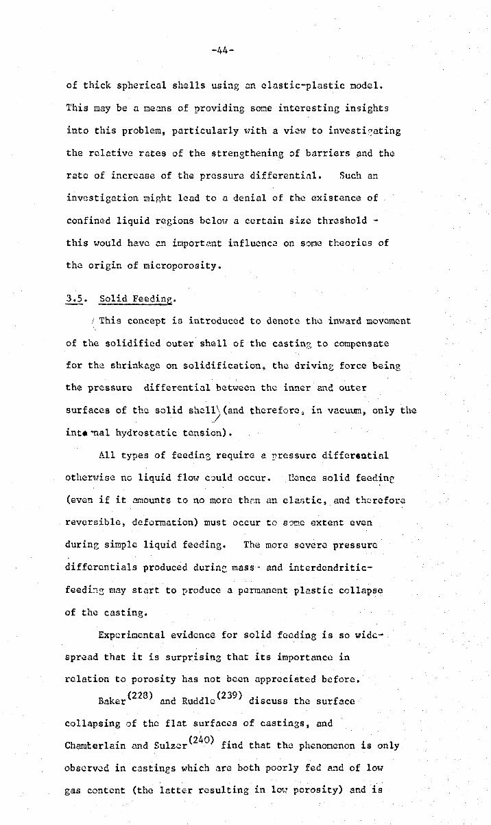
-44-
of thick spherical shells usbg an elastic-plastic model.
This may be a means of providing some interesting insights
into this problem, particularly t-lith a vie~., to investi8ating
the relative rates of the strengthening of barriers and the
rate of increase of the pressure differential. Such an
investigation might lead to a denial of the existence of
confined liquid regions belotl a certain size threshold -
this t-lould have en importent influence on some theories of
the origin of microporosity.
3.5. Solid Feeding.
This concept is introduced to denote the inward movement
of the solidified outer shell of the castinz to compensate
for the shrinkage on solidification, the drivine force beine
the pressure differential between the inner and outer
surfaces of the solid shel1\(and therefore~ in vacuum, only the /
int.~al hydrostatic tension).
All types of feedin3 require a rressurc differ«utial
other~.,ise no liquid flot-1 could occur. llence solid feedine
(even if it amounts to no more thnn an clastic, and therefore
reversible, defurmation) must occur to so~c extent even
during simple liquid feeding. The more severe pressure
differentials produced during mass'- and intcrdendritic-
feedi~~ may start to produce a permanent plastic collapse
of the casting.
Experimental evidence for solid feeding is so wide'·
spread that it is surprising that its importance in
relation to porosity has not been appreciated before.
Baker(228) and Ruddle(239) discuss the surface
collapsing of the flat surfaces of castings, and
Cham!:.erlain and Sulzcr(240) find that the phenomenon is only
observed in castings which arc both poorly fed and of low
gas content (the latter resulting in lov~ porosity) and is

-45-
e1i~inatcd by reversing these two factors; thus solid
feeding can operate in the same way as liquid feeding to
reduce porosity. Jackson(241) provices some quantitative
data on the overall shrinkage of castings. Always, however,
the surface sinks have been nttributcd solely to atmospheric
pressure, wl1i~reas if part of the drivin3 force results from
the hycrostatic tension in the residual liquid because of
the 'solidification contraction, then sinks nearly as severe
could have been produced in vacuun.
Recent German work (249,250) docs draw ~ttention to thi!;
phenonenon in relation to the overall feeding of the
contraction on solidification, an<! refers to it as the •
"einfa11volur.ten".
Some early theories of the origin of microporosity
assumed th~t if a small interdend~itic volume of liquid
metal were isolated from supplies of feeding liquid then a
pore must n':lccssarily occur to make up the volume deficit
on freezing (251-'255) • This can nOH' be seen to be an
oversinplification. Both Al1en(1) and vn1ittenbergcr and
Rhines(2) appreciated that a negative pressure would arise
in such a confined liquid and the latter authors qualitatively
discuss nucleation of pores under such conditions.
In view of the pore nucleation conditions outlined in
Section 2., it is of interest to determine exactly what
shrinkage pressures can be developed in a solidifying
casting. For the following quantitative attempts at this
problem spherical symmetry has been universally adopted
(inner and outer radii of the solidified shell are respectively
a and b)~ by virtue of its ecometry the sphere is the nost
difficult shape to collapse, and therefore results in the
highest possible values for the shrinkage pressure.
Sini1ar analyses could be developed for other geon~tries but
in any case s1:1a11 liquid regions which are entirely enclosed
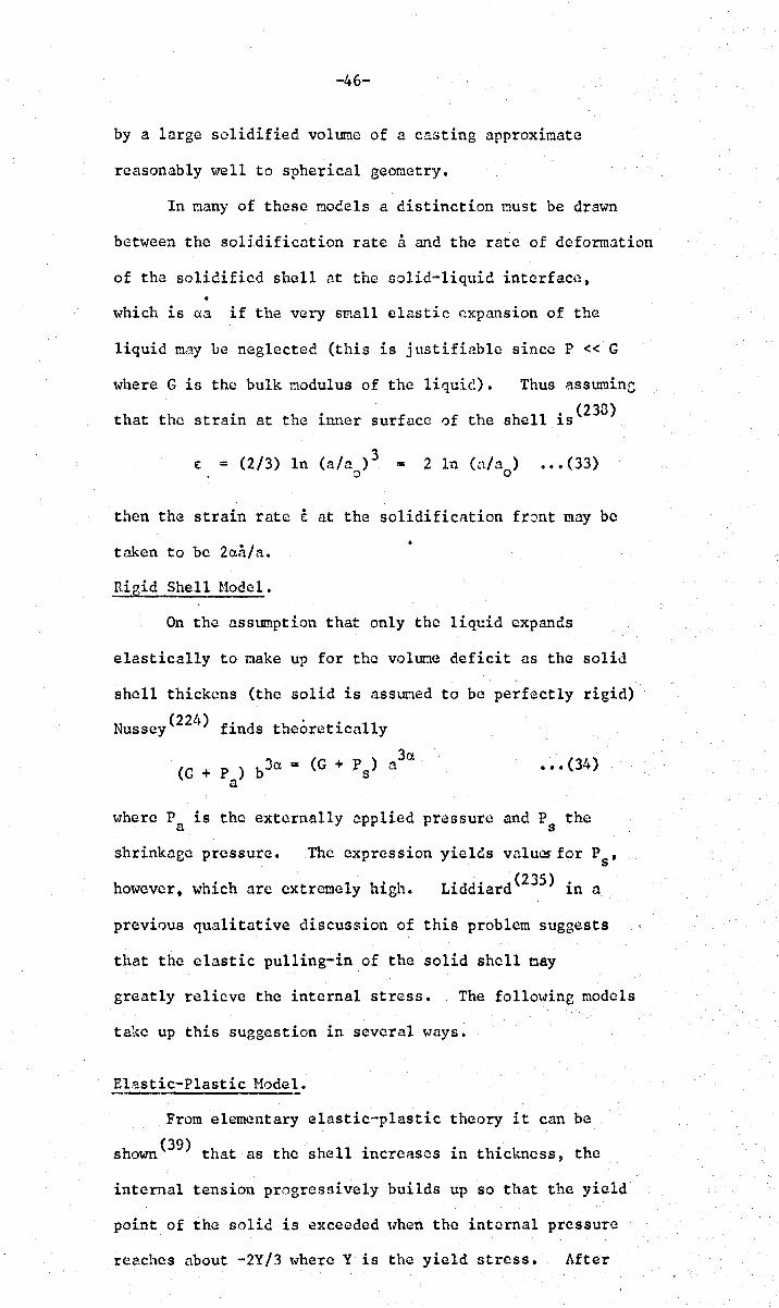
-46-
by a large solidified volume of a casting approximate
reasonably ~I]ell to spherical geometry.
In many of these models a distinction must be drawn
between the solidification rate a and the rate of deformation
of the solidified shell at the solid-liquid interface,
which is aa if the very small elastic expansion of the
liquid may be neglected (this is justifiable since P « G
where G is the bulk modulus of the liquid). Thus assuminc
that the strain at the inner surface of the shell is(233)
= (2/3) In (a/a )3 o = ••• (33)
then the strain rate E at the solidification front may be
taken to be 2o.a/a.
!igid Shell Model.
On the assumption that only the liquid expands
elastically to make up for the volune deficit as the solid
shell thickens (the solid is assuned to be perfectly rigid)
Nussey(224) finds thebretically
bJa = (G + Ps ) a3a (G + P )
••• (34) a
.. .,here P is the externa.lly applied proassurc and P the a s
shrinkage pressure. The expression yielcls valu~for Ps '
however, which are extremely high. Liddiard(235) in a
previous qualitative discussion of this problem suggests
that the elastic pulling-in of the solid shell oay
greatly relieve the internal stress. The follmving models
take up this suggestion in several ways~
Elastic-Plastic Model.
From elementary elastic-plastic theory it can be
shown(39) that as the shell increases in thickness, the
internal tension progressively builds up so that the yield
point of the solid is exceeded when the internal pressure
reaches about -2Y/3 where Y is the yield stress. After
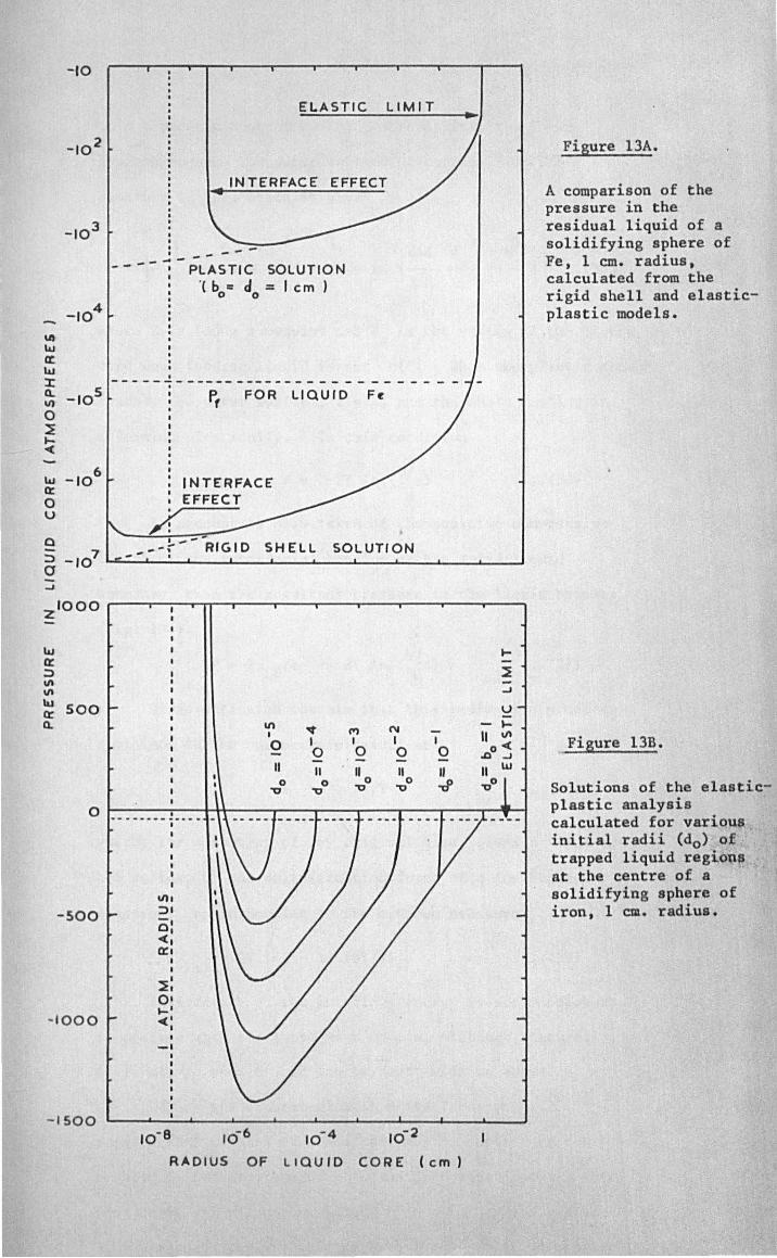
-10
_104
'" ~ « ~
J: Cl. _105 II)
0 ~ .... ~
~ ex:
_106
0 u
0 ::> _107 a ..J
zlOOO
~ ex: ::>
'" '" IU 500 ex: Cl.
ELASTIC LIMIT
... INTERFACE EFFECT
---.... - --- - - - PLASTIC SOLUTION
'( b c cI = I em) o 0
I - -- - -- - - -- -- - -- - - - - - - - - - - - - - - - -P, FOR LIQUID F~
I INTERFACE : EFFECT
/: _---r---RIGID SHELL SOLUTION
\I) ~ M N
I
0 I , I 0 0 0
II II " II 0 0 0 ~ ~ ~
, 0
... ~ ..J
U
o r----,,~~~--~--_T--~--__ --~--__ ~~
-SOO
- 1000
- 1500
_ •• _ ... __ jW ..... _
I
I
VII ::>1 0: ~I 0::1
I I
~: 0 1
.... ' ~:
• -I
10-8 106 10- 4 10-2
RADIUS OF LIQUID CORE (em)
Figure l3A •
A comparison of the pressure in the residual liquid of a solidifying sphere of Fe, 1 em. radius, calculated from the rigid shell and elasticplastic models.
Figure l3B.
Solutions of the elasticplastic analysis calculated for varioQ~ initial radii (do> of trapped liquid regiou$ at the centre of a solidifying sphere of iron, 1 em. radius.
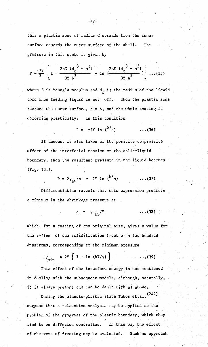
-47-
this a plastic zone of radius C spreads fron the inner
surface towards the outer surface of the shell. The
pressure in this state is given by
2aB + In {
(d .~ a ) 3 3 J o 3 } ••• (35)
3Y a
where E is Young's modulus and d is the radius of the liquid . 0
core when feeding liquid is cut off. ~~en the plastic zone
reaches the outsr surface, c • b, and the ~"hole casting is
deforming plasticnlly. In this condition
••• (36)
If account is also taken of the positive compressive . effect of the interfacial tension at the solid-liquid
boundary, then the resultant pressure in the liquid becomes
(Fig. 13.).
• •• (37)
Differenti~tion reveals that this expression predicts
a minimum in the shrinkage pressure at
a • Y LS/Y ••• (38)
which, for a casting of any original size, gives a value for
the r:'.~ius of the solidification front of a few hundred
Angstroms, corresponding to the minimun pressure
P. = 2Y, [ 1 - In (bY Iy) J mlu
••• (39)
This effect of the interface energy is not mentioned
in dealing t"ith the subsequent models, although, naturally,
it is altvays present and can be c1C;llt with as above.
During the e1astic'-plastic state Tabor et .al. (242)
suggest that a relaxation analysis may be applied to the
problem of the progress of the plastic boundary, which they
find to be diffusion controlled. In this limy the effect
of the rate of freezing may be evaluated. Such an approach
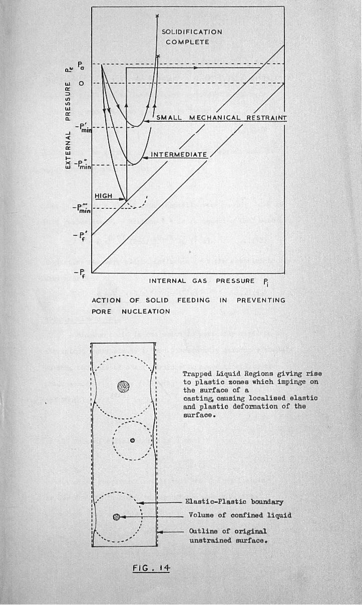
o...~
LLI a:: ::> \I) \I)
LLI a:: Q.
...J < Z a:: LLI
Pa
0
... .. >< -P. . LLI mIn
SO LID I FICA TI 0 N
COMPLETE
P. '" - .. ------mIn
- r.' f
-P. f
INTERNAL GAS PRESSURE p, I
ACTION OF SOLID FEED I NG IN PREVENTING
POR ENUCLEATION
.. -- - ... ..
Trapped Liquid Regions giving rise to plastic zones which impinge on the surface of a castin& causing localised elastic and plastic deformation of the surface •
' .... --l+--- Elasti c-Plastic boundary
if ' , . , , . .-. .. .. - .,. ...
, • • Volume of confined liquid . . , I
I ... Outline of original unatrained surface.
FIG. 14
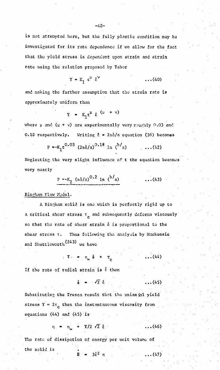
-43-
is not attenpted here, but the fully plastic condition may be
investicated for its rate depcndenc~~ if \~e a11O\I for the fact
that the yield stress is eependcnt upon strain and strain
rate using the relation proposed by Tabor
• •• (40)
and naking the further assumption that the strain rate is
approximately uniform th~n
Y .. Kl t].l E (].I + v)
where ].I and (].I + v) are experimentally very r'.:'Iu;::hlyCl.03 ane
0.18 respectively. tvriting E .. 2a.a/,~ equation (36) becomes
• •• (42)
NeglectinG the very slight influence of t the equation becomos
very nearly
••• (43)
Binpham Flow Hodel. ! -
A Bin(jhrun solid is ono \vhich is perfectly rigid up to
a critic~.l shear stress -r and subsequently defoms viscously c
so that the rate of ~hear strain s is proportional to the
shear stress -r. Thus followb.g tho analy::ds by l1ackensie
and Shuttlcworth(243) we have
- Tc .. n ~ + ~ 01) C
If the rate of radial strain is E then
s ..
Substitutin3 the Trcsca result thnt the uniaxial yield
stress Y = 2-r then the instantaneous viscosity from c
equations (44) and (45) is
n .. n<J) + Y/2 12 E • •• (46)
Th.e r:ltc of dissipation of energy per unit voh.lI!lC of
the solid is • E .. 3£2 n • •• (47)

-49-
so that the rate of dissipation of enereY throughout the
whole shell is
= • •• (48)
We may no\-, deduce that if the rate of radial displacement
is . then the effective force generated at the inner surface o.a
of the
to the
shell is E/o.a, so thl1t
restraint of the shell
3 pa_ 2. a aa
= - • a a
the corresponcline pressure •
is E/4rra2 an. Therefore
••• (49)
t.Jhcn the viscosity is zero the expression rcc.uces to
p = 3Y --rz • •• (50)
due
which compares favourably (to \·dthin 6%) with that deduced
from the elastic-plastic analysis (equation 36).
tnlen the yield stress is zero the Bingham solid behaves
as a classical viscous oaterial. lilicn b »a equation (49)
simplifies to
p = . -4 n aa!n 00
• •• (51)
or if we nay describe viscosity as a process characterised
by an activation energy Q, then the shrinkage pressure for a
purely viscous material becomes
." • (52)
Creep Hodels_"
For an inconpressible material the radial velocity
f 1 d··· b· (2/ 2). h o an e ement at ra lUS r lS elvcn y u = a raw ere u
is the radial clisplacement of the element. Consequently
the radial strain rate is
£ ... - 2 a2 " a ••• (53) -3-
r
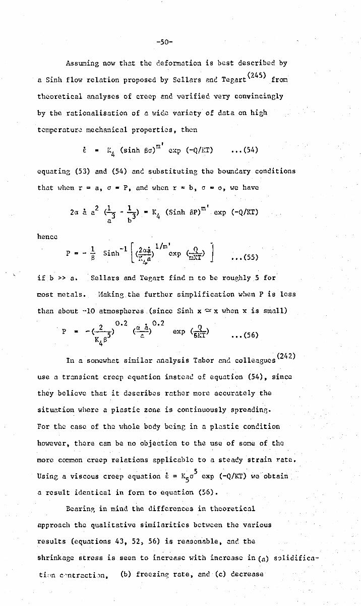
-50-
Assuming now that the deformation is best described by
a Sinh flow relation proposed by Sellars and Tegart(24S) fron
theoretical analyses of crecp and verified very convincinBly
by the rationalisation of n \vic:c variety of data on high
tcmperatur~ mechanical properties, then
t
E = I~4 (sinh 8(1)m cxp (-Q/KT) • •• (54)
equating (53) and (54) and substituting the bounclary conditions
that \\Then r = as (1 = P, anc tvhen r = b, (1 = 0, we have
2 1 1 ' 2a a a (-- - --) = K4 (Sinh SP)m exp (-Q/KT) a
3 b3
hence
p = 1 - -13 • •• (55)
if b » a. Sellars and Teeart find n to be roughly 5 for
tlost metals. Haking the further simplification when P is less
than about .. ·10 atmospheres (since Sinh x ~ x v1hcm x is small)
P 2 0.2
= -(._) K 8
5 4
exp (5~T) • •• (56)
(242) In a sooewhat similar analysis Tabor and colleagues
use a transient crecp equation instead of equation (54), since
they believe that it describes rather more accurately the
situation where a plastic zone is continuously spreadini':i.
For the case of the '\'lho1e body bcinr, in a pl~stic condition
however, there can be no objection to the use of some of the
more comnon creep relations applicable to a steady strain rate.
U •• . • K 5 ( Q/KT) b' s~ng a V1SCOUS creep equatlon E = ~5cr exp - we 0 taln
a result identical in forn t.o equation (56).
Bearinp, in mind the differences in theoretical
approach the qualitative similarities between the various
results (equations 43, 52, 56) is re8Gonable, and the
shrinkage stress is seen to increase with increase in (a) s~lidifica-
tLm c'~ntracti:m, (b) freezing rate, and (c) decrease

-51-
in radius of the liquid core. Quantitative results arc not
easy to obtain from equations (52) ane (56) since there is a
great lack of data, but equation (37) is vlOrked aut in detail.
The results arc given in Fie. 13. and show a maximum shrinkage
pr~ssurc of the order of -1500 atmospheres. This figure falls
to -900 atmospheres if other yield point data is used(39).
In either case the maximtnn hydrostatic tensile stress is scverD.1
orders of nagnitude lower than that required to homogeneously
nucleate a pore, so that in the absence of suitable nuclei,
a voluoe of trapped liquid will freeze sound due to the inward
collapse of the surrounding casting. vJe m~y also conclude
that if there are n nuclei (including inclusions, bubbles or
alpha decays) present per unit volume of casting during
freczing~ and if there arc IOn volumes of liquid trapped
between dendrite arms, then approximately 90% of these regions
will freeze sound.
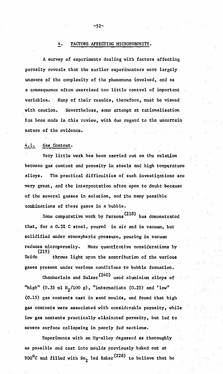
-52-
4. FACTORS AFFECTING MICROPOROSITY.
A survey of experiments dealing with factors affecting
porosity reveals that the earlier experioenters were largely
una~l7are of the conplexity of the phenomena involved, and as
a consequence often exercised too little control of important
variables. Many of their results, therefore, must be viewed
with caution. Nevertheless, some attempt at rationalisation
has been made in this review, with due regard to the uncertain
nature of the evidence.
4.1. Gas Content.
Very little work has been cerried out on the relation
between gas content and porosity in steels and high temperature
alloys. The practical difficulties of such investigations are
very great, and the interpretation often open to doubt because
of the several gasses in solution, and the many possible
combinations of these gases in a bubble.
Some comparative work by Parsons(2l8) has demonstrated
that, for a 0.3% e steel, poured in air and in vacuum, but
solidified under atmospheric pressure, pouring in vacuum
reduces microporosity. More quantitative consieerations by (219)
Heide throws light uron the contribution of the various
gases present under various conditions to bubble formation.
Chamberlain and Sulzer(240) used aluminium alloy~ of
"high" (0.35 ml H2/l00 g), "intermediate (0.25) and 'low"
(0.15) gas contents cast in sand moulds, an~ found that high
gas contents were associated with considerable porosity, while
low gas contents practically eltminated porosity, but led to
severe surface collapsing in poorly fed sections.
Experiments with an Ug-al1oy degassed as thoroughly
as possible and cast into moulds previously baked out at
9000e and filled with S02 led Baker(228) to believe that he

-53-
had conclusively proved the existence of shrinkage porosity.
However, realising the inadequacy of conventional degassing
techniques, ~lliittenberger and Rhines(2) boiled Mg-alloys in a
carbon crucible in an atmosphere of pure dry Argon, until a
najor proportion of the alloy had boiled away. The oetal
was cooled while remaining under its protective atmosphere and
subsequently examined for porosity. lione was revealed by
metallographic exacination, or by radiosraphy, although
density results seemed to indicate a porosity level of 0.02
to 0.10% w'hich C'annot be far outside their experimental error.
Exposure of the melt to various gaDes, particularly H2 and
H2S, vastly increased the porosity t~ al~ost 40%. After this
demonstration of zero (or nearly so) porosity in the absence
of gas, they also show that porosity can be found in gas-
containing alloys which expand on freezing. They conclude
that porosity cannot be nucleated by shrinkage .:1':.:n(;:, but can
be nucleated by gas in the entire absence of shrinkage.
However, once nucleated, the growth and the final size of the
pore can, in certain cases, be practically entirely gover~cd
by shrinkage.
It is interesting that the ebove experiments are
confirmed by Mrs. Beeton(256) who recoffiQends the use of
pre-boiled water (which, it must be renembered, expands on
freezing) if clear ice-cubes are required.
Flemings.. and co-workers (304) deduce theoretically
that the applied pressure, Pa, during casting reduces the
percentage volume porosity by (a) increasing the SOlubility
of the gas in the solid and (b) compressing existing pores.
% Porosity • (C- K P I) . p Tf /273 Pa o s a s ••• (60)
Co is the original concentration of gas (in ml/IOO g), Ks
Sievert's constant for the solid, p density of sound solid, s
Tf freezing point (OK). The derivation assumes that the

-54-
pressure in the bubbles is equal to P which explains why a
this fo~u1a yields values for porosity which are at least a
factor of 3 too large. Later work ( 230) by the sane school
shows that the equilibrium partial pressure Ps ' of a dissolved
gas is given by equation (20). Considering only gas as the
source of pores, a critical amount of gas Cc must be present
for pores to form ~t all. This follows directly by setting
Pg • Pa ' Co - Cc and fL· 0
C K P 1 c· S a ••• (61)
The formula~ (20, 60, 61) neglect surface tension and
the mode of solidification, so these authors proceed to show
• that surface tension increases the amount of gas which can
be present initially without forming a pore, particularly
when nT is large. Correcting some minor errors in the
original paper, the equations arc
••• (62)
••• (63)
To determine C , equations (62) and (63) are solved c
simultaneously to eliminate the critical bubble size. rc'
Provided Cc is greater than that given by equation (61) the
final solid is supersaturated. This effect c~n be very
great if the mode of solidification yields a high value of
nT, so that little gas is available for the production of
porosity.
Although predictions must be made with caution when
using the above equations since they neglect the effects of
shrinkage, there is a fair volume of experimental work to
justify the view that a critical gas content must bo
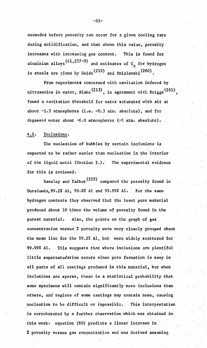
-55-
exceeded before porosity can occur for a given cooling rate
during solidification, and that above this value, porosity
increases with increasing gas content. This is found for
aluminium a110ys(41,257-9) and estimates of Cc
for hydrogen
in steels are given by Heide(219) and Smialowski(260).
From experiments. concerned with cavitation induced by
I •. BI k (213) • . t B' (261) u trason1CS 1n water, a e , 1n agreement ~ntl.l r1ggs ,
found a cavitation threshold for water saturated with air at
about -1.3 atmospheres (Le. -0.3 atm. absolute), and for
degassed water about -6.0 atmospheres (-5 atm. absolute).
4.2. Inclusions.
The nucleation of bubbles by certain inclusions is
expected to be rather easier than nucleation in the interior
of the liquid metal (Section 2.). The experimental evidence
for this is reviewed.
Ransley and Talbot(259) compared the porosity found in
Duralumin,99.2% AI, 99.8% Al and 99.99% AI. For the same
hydrogen contents they observed that the least pure material
produced about 10 times the volume of porosity found in the
purest material. Also, the points on the graph of gas
concentration versus % porosity were very closely grouped about
the mean line for the 99.2% AI, but were widely scattered for
99.99% AI. This suggests that where inclusions are plentiful
little supersaturation occurs since pore formation is easy in
all parts of all castings produced in this material, but when
inclusions are sparse, there is a statistical probability that
some specimens will contain significantly more inclusions than
others, and regions of some castings may contain none, causing
nucleation to be difficult or impossible. This interpretation
is corroborated by a further observation which ll1aS obtained in
this work: equation (60) predicts a linear increase in
% porosity versus gas concentration and ,~as derived assuming

-56-
easy nucleation (i.e. neglecting surface tension) whereas if
nucleation is hindered by surface energy considerations the
relations become more complex (eqtns. 20 t 62, 63) and non-
linear. The experimental results show a good straight line
for the 99.2% Al and a curve for 99.99% AI. All other
results on relatively iopure Al show linear relations(54,55,57~
The Straube-Pfeiffer test for the gas content of Al
alloys was carefully investigated by Drondyke and Hess(262).
They concluded that the test was insensitive to hydrogen
contents belo~., 0.3 ml/lOO g. because of the influence of
inclusions. By filtration of the liquid metal to remove a
large percentage of the inclusions a specimen which appeared
"gassey" in the test (Le. formed a large number of bubbles
during solidification) could be made to appear perfectly
degassed, although the gas content was unchanged. They
point out that although the test does not provide an
indication of gas content at these low levels of concentration~
it does provide an estimate of pore-forming potential of
the liquid, l-Thich is perhaps, of greater interest to the
foundryman.
The theoretical considerations in Section 2. on the
action of solid surfaces in aiding pore formation are given
weight by the experiments of Abramov and Teumin(263) who
induce cavitation in liquid Bi by the immersion of a solid
surface vibrating at ultrasonic frequency. The threshold
pO~ler imput . to produce cavitation at the solid surface was
found to be a function of <p, which l1aa varied by plating
the surface with various metals.
It is therefore feasible that liquid metal history
may affect the amount of porosity, since a sufficient time
at high temperature may cause certain harmful inclusions to
be taken into solution, and so 'deactivating' the liquid
metal (i.e. reducing its pore forming potential) (264) •

-57-
4.3. Freezing Distance L, and Temperature Gradient dT/dx.
Considering an element of distance dx in the mushy zone
of a solidifying alloy, across which there exists a temperature
difference dT, if the temperature gradient is linear then
. integrating across the width L of the mushy zone gives
L .. (dT/dx) ••• (64)
where 6Tf is the freezing range (under equilibrium conditions
this is the liquidus temperature TL minus the solidus
temperature T ). s This relation is necessarily rather rough
since real temperature gradients are far from linear, and
6Tf may be effectively increased by s?veral hundred percent
during rapid freezing (for an alloy of a eutectic system 6Tf
becomes (TL .- T ) where T is the freezing point of the eutectic). e e
L may of course be obtained directly by appropriately placed
thermocouples in the solidifying castine.
Most investigations into the causes of porosity have
used either the temperature gradient (usually measured at the
solidus) or the freezine range as critical parameter, and have
neglected L which would be expected to be a par~eter rather
more closely related to the incidence of porosity than either
6Tf or dT/dx separately, and more particularly since L appears
in all the pressure drop formulae (equations 26-29).
Several authors have claimed the existence of a minimum
temperature gradient for the elimination of porosity in n
particular alloy. Some results are listed in Table 7.
together with a minimum value of L calculated from eqtn. (64).
Two interesting observations may be made: (a) most of the
minimum estimates of L exceed normal casting dimensions (it
follows that in general, therefore, the mushy zone fills the
casting), and (b) the values are remarkably scattered.
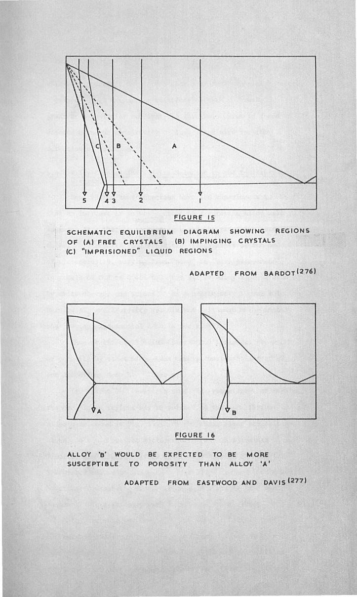
, , , , , , B
, A , , ,
, , \
, , , , , ,
5 2
FIGURE 15
SCHEMATIC EQUILIBRIUM DIAGRAM SHOWING REGIONS
OF (A) FREE CRYSTALS (B) IMPINGING CRYSTALS
(e) "IMPRISIONED" LIQUID REGIONS
ADAPTED FROM BARDOT(276)
A B
ALLOY 'B' WOULD
SUSCEPTIBLE TO
FIGURE 16
BE EXPECTED TO BE MORE
POROSITY THAN ALLOY 'A'
ADAPTED FROM EASTWOOD AND DAVIS (277)

-58-
Brac,-·_l n (265) do""s not' 1" t ' d' t t '! ~ ~ gLve a lml lne gra leu 0
eliminate porosity, but infers that a gradual transition occurs.
F 1 ' (266-7) , h' f h h h 1 d emlngs (~etuGS t e eXlstence 0 suc a t res 0
gradient by pointing out that the threshold which is found
depends upon the sensitivity of the method used for the
detection of porosity.
4.4. Alloy Composition and its Re1etion t.o the Equilibrium Diag~.
Equi1ibriuo considerations have led experiments to expect
that an increase of solute content of a eutectic alloy will
increase ~Tf' thereby increasing L and the resulting porosity.
Czikel (275) reports some subjective assessments of the amount ;
of microporosity, varying from ilnom~" to "very pronounced",
in steels of 0.2 to 0.46% C. For all 14 alloy systems studied
by Hhittenberger ruld Rhines(2) an approximately linear relation
betwe~n 6Tf and %Porosity was claimed (although unfortunately
the precise experimental data is not given).
Ho~ever the equilibrium ciagram nay influence the amount
of porosity by other means than merely considerations of ATf
and its effect. upon L. These are
(a) Bardot(276) suggests that the rrobabi1ity of forming
trapped liquid regions May be related to the equilibrium
diagram as sholVll in Fig. 15. Of the three alloy compositions
shown, he 'I'I1ou1d predict rnicroporosity only in (3) since
"imprisioncd" liquid regions would be absent in (1) and (2).
The writer has added c1bys 4 - 5 in ilhich trapped liquid ,.,ou1d
be expected under the non-equilibrium conditions in a real
casting. This is dealt 'vith in greater detail later.
( ) d ' (227). h' f h b Eastwood an DaVles pOlnt out t at 1 t a
contours of the liquidus and solidus surfaces are such as to
permit a relatively large proportion of liquid to remain at
the lower part of the solidification range, than the alloy
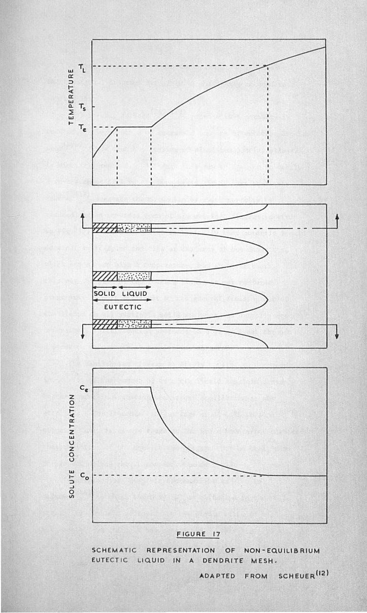
'T -----------------------------UJ l a: :::>
~ a: UJ a. Ts ~ UJ l-
T",
~-... ~ .-SOLID LIQUID
EUTECTIC
.. -. : ... -.... ~. ,....-fC7j~r.,H~,~, ,-.. ,;,: ',' '.
Cc Z 0 t-~ a: I-Z UJ
U Z 0 U
FIGURE 17
SCHEMATIC REPRESENTATION OF NON-EQUILIBRIUM
EUTECTIC l.IQUID IN A DENDRITE MESH,
ADAPTED FROM SCHEUER (2 )
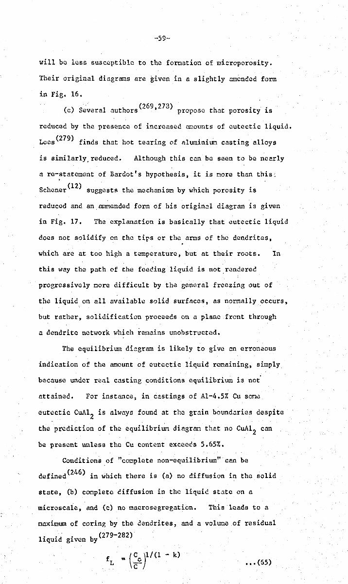
-59-
will be less sU3ccptible to the formation of mi=roporosity.
Their original diagr~s are given in a slightly amended form
in Fig. 16.
(c) Several authors(269,273) propose that porosity is
reduced by the presence of increased anounts of eutectic liquid.
Lees(279) finds that hot tearing of aluminium casting alloys
is similarlY,reduced. Although this can be seen to be nearly
a re-statemcnt of Bardot' s hypothesis ~ it is nore than this.; '.
Schener(12) suggests the mechanism by which porosity is
reduced and an.amfficnded form of his original diagram is given
in Fig. 17. The explanation is basically that eutectic liquid
docs not solidify on. the tips or the arms of the dendrites,
which are at too high a temperature, but at their roots. In
this way the path of the feeding liquid is not.rcndered
progressively more difficult by the general freezing out of
the liquid on all available solid surfaces, as normally occurs,
but rather, solidification proceeds on a plane front through
a dendrite network which remains unobstructed.
The equilibrium diagram is likely to give an erroneous
indication of the amount of eutectic liquid remaining, simply
because under real casting conditions equilibrium is not'
attained. For instance~ in castings of Al-4.5% Cu sone
eutectic CuAl2 is always found at the grain boundaries despite
the prediction of the equilibrium diagram that no CuAl 2 can
be present unless the eu content exceecs 5.65%.
Conditions of "complete non-equilibrium" can be
defined(246) in which there is (a) no diffusion in the solid
state, (b) conplete diffusion in the liquid state on n
microseaie, and (e) no macrosegregation. This leads to a
maximum of coring by the dendrites, and a volume of residual
by (279-282) liquid given
•• ' (55)
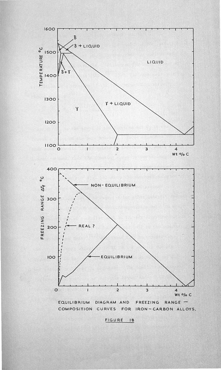
1600
S
u 0 ISOO w cr:: :::l LIQUID t( cr:: ~1400 ~ w ~
1300 Y + liQUID
'(
1200
1100 ~~~~~~~~~~~~~~~~~~~~~~~~~ o 2 3 4
Wt % C
400 , U
, , 0
~ NON - EQUlll BRIUM <3 41 C> 300 Z ~ ct , C>
, Z
, I
N 200 ,- REAL? w , w , cr:: I lL ,
100 ~--EQUILIBRIUM
o 2 3 4 Wt % C
EQUiliBRIUM DIAGRAM AND FREEZING RANGE-
COMPOSITION CURVES FOR IRON-CARBON ALLOYS.
FIGURE IS
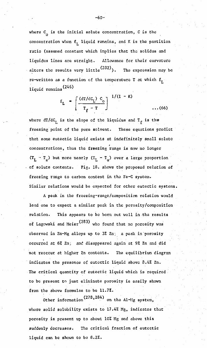
-60-
where C is the initial solute concentration, C is the o
concentration when fL liquid rcnains, and K is the partition
ratio (assumed constant which implies that the solidus and
liquidus lines are straight. Allowance for their curvature
alters the results very little(282». The expression may be
re-writteo as a function of the temperature T at which fL
liquid remains(246)
1-(dT/dC) C J 1/(1 - K)
f III L 0 L
T ". T f
••• (66)
where dT/dCL is the slope of the liquidus and Tf
is th~
freezing point of the pure solvent. These equations predict
that some eutectic liquid exists at indefinitely small solute •
concentrations, thus the freezing range is now no longer
(TL - Ts) but more nearly (TL - Te) over a large proportion
of solute contents. Fig. 18. shm-ls the proposed relation of
freezing range to carbon content in the Fe-C system.
Similar relations would be expected for other eutectic systems.
A peak in the freezing-range/composition relation would
lead one to expect a similar peak in the ,porosity/composition
relation. This appears to be born out well in the results
of Lagowski and Meier(283) who found that no porosity was
observed in Zn-Mg alloys up to 3% Zn: a peak in'porosity
occurred at 6% Zn; ane disappeared again at 9% Zn and did
not reoccur at higher Zn contents. The equilibriun diagr&u
indicates the presence of eutectic liquid above 8.4% Zn.
The critical quantity of eutectic liquid \-lhich is required.
to be present to just eliminate porosity is easily shown
from the above formulae to be 11.7%.
Other ' f t' (278,284) on th'" Al If 1n orma 10n "'" -.g system,
where solid solubility exists to 17.4% Mg, indicates that
porosity is present up to about 1070 Ug and above this
suddenly decreases. The critical fraction of eutectic
liquid can be shown to be 8.2%.
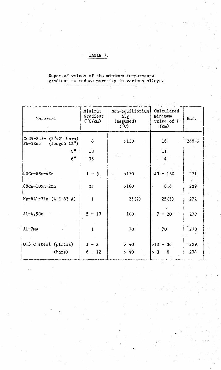
TABLE 7.
Repartee values of the minimum temperature gradient to reduce porosity in various alloys.
Hinimum Non-equilibrium Cnlculated
l1ntcria1 Gradient ~Tf minimum (oC/crJ.) (assumed) vn1ue of L
(0 C) (em)
Cu3S-Sr.5- (2 "x2" bars) 8 >130 16 Pb-5Zn5 (length 12")
9" 13 11 •
6" 33 4
88Cu-8Sn-4Zn 1 - 3 >130 43 - 130
88Cu-10Sn'<~ Zn 25 >160 6.4
Mg-6Al-3Zn (A Z 63 A) 1 25 (?) 25 (?)
Al-4.Seu 5 - 13 100 7 - 20
Al-7Me 1 70 70
0.3 C steel (plates) 1 - 2 > 40 >18 - 36
(b.:!rs) 6 - 12 > 40 > 3 - 6 .
-Ref.
268--;
271
229
272
270
273
229.
274
"61-
4.5. A~te of Solidification, dm/d~.
Budgen(285) reports that slotver coo line produced greater
porosity in AI-alloys. He explains this on the assUI:lption that
the greater time interval, 6t, between the liquidus and solidus
fronts allows more gas to be precipitated. Furthermore, the
greater width of the pasty zone facilitates the entrapping of
gas bubbles which \1ould otherwise escape by floating out to the
surface. For similar materials j Ransley and Talbot(259) also
found that the amount of porosity was a direct function of the
time interval 6t. By casting an AI-alloy, saturated with
hydrogen, into steel moulds at various temperatures,
vfuittenberger and P~ines(2) showed 'that porosity was inversely
proportional to the rate of freezing) although a fall in porosity
at very slow rates vias attributed to loss of gas from the
surface of the ingot durin3 solidification. Also~ using
Al-6% Cu and Al-5% si Hith hydrogen contents of 0.2 and
0.4 ml/lOO g. Bhattacharjya(206) showed that for 6t between
about 20 and 200 seconds ~ the relation bet~-leen porosity and
6t was closely linear 'vith a slope of 1% porosity per
100 seconds solidification interval. However for low gas
contents (0.16 ml/lOO g.) and shorter solidification
intervals (10 to 50 seconds) this linear relation broke down,
and, despite sone scatter, a reverse trend is perceptible in
the results.
It is feasible that at lOll gas contents and high
solidification rates, viscous flow bettvcen dendrites becomes
important. Allcn's formula (eqtn. 26.) predicts that the
pressure drop along an interdendritic channel is directly
proportional to the rate of solidification. The same
implication is present in subsequent formulae (equations 27-23)
because of the heat £10\-1 term )..
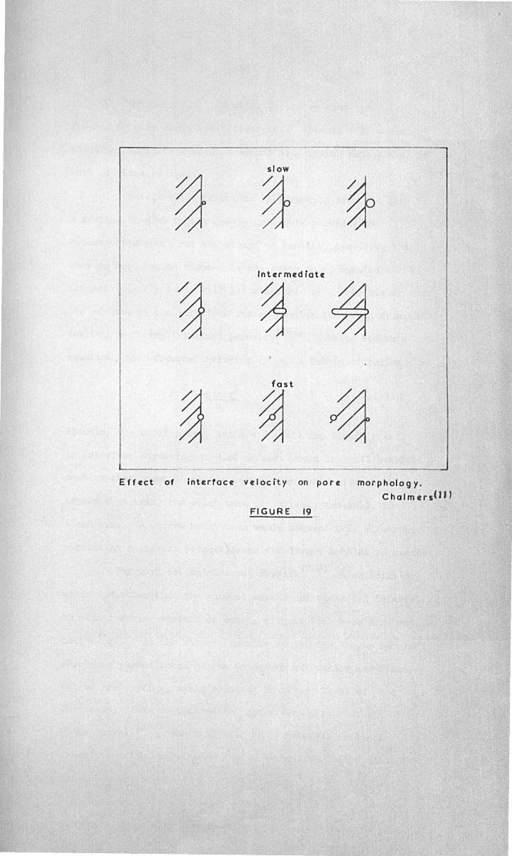
slow
~ Inter m~d lot~
~ ~ ~ •
fast
~ ~ ~ Eff~ct of InterfQC~ v~loctty on por~ morphology.
ChCJlm~rs(JJ)
FIGURE 19
,
-62-
The grain size and dendrite arm spacing are both
reduced by more rapid solidification. Formula (28) would
therefore indicate a reduced amount of porosity from either or
both of these changes.
mlere a solid interface is advancing fron the base of
a casting, and ,,,here the overlying liquid provides an
unobstructed route for the escape of bubbles, providing that
they do not become trapped in the pasty zone, bubbles which
are sufficiently large will float up'tlards at a rate higher than
the advance of the interface and so completely escape fro~ the
. d" f' 1 . (237) cast1ng, re uC1ng ~ts 1na poros1ty • Using Stokes's
equation, the terminal velocity v: of a bubble of radius r is
••• (67)
Assuming ~ = 0.025 poise, and p = 7 g/cc. for liquid steel p
an interface advancing at 0.10 cm/sec. would trap all bubbles
smaller than about 10 micron radius, but would allow' bubbles
larger than this, and lv-hich were not already el1r.leshed s to
float out. A narrow mushy zone would enhance this effect by
permitting a greater proportion of the larger bubbles to escape.
The work of Chal~ers and Ne"kirk(288) on solidifying
water indicates that the rate of advance of the solid interface,
in skin freezing systems at least, affects both pore size and
morphology. At the slower freezine rates~ the larger bubbles
which are pushed ahead of the interface may detach and flaat
out of the casting, again reducing the fin~l level of porosity.
This study makes an interesting comparison '71th that of
UhLman et.al. (289) who find that there exists a critical
interface velocity for each type of inclusion, below which
particles are rejected, i.e. pushed along by the interface,
and above '''hich they are entrapped. By this means, slowly
frozen castings will have a higher density of inclusions
·-63-
segregated in the residual liquid, and therefore easier pore
nucleation~ while, conversely, fast frozen castings will be
cleaner in the interdcndritic regions, tending to suppress
pore nucleation. This effect is not likely to be very
irnportant in cor:lIilcrcinlly pure alloys sinc(3 even if very f£tst
cooling produced no segregation of inclusions, there would still
be a sufficient density of inclusions in the residual liquid
for effective pore nucleation.
Solidification rate will also affect microsegregation
of solutes, and the vol~e fraction of residual liquid, fL'
This is dealt with more fully under Section 4.4. from w'hich
it is evident that most generally ~ncountered solidification
rates result in perfectly non-equilibriun structures and
there.fore constant Cll1lounts of fL'
Finally, solidification rate, in conjunction with
certain other paraneters(l26), will d2termine the mode of
freezinB; whether the interface will be planar, cellular,
dendritic or ,,,,hether general equiaxial nucleation of the
solid throughout the melt will occur. The planar interface
will produce no microporosity (unless it be centreline
porosity) and the other varieties of solidification are
described analytically in S~ctLn 3.3. Cellular and
dendritic solidification may result in hiehcr concentrations of
segregates than a planar interface (290) •
Surrnnarising, a high solidification rate 'lrlill produce
low'or porosity because of (a) smaller grain size ~ (b) smaller
dendrite arm spacing; (c) shorter solidi.fication interval, f.t· I
(d) shorter freezing distance, L: (c) an increase in residual
liquid, £L: (f) few segregated inclusions. Other factors
which ,-1i11 operate in opposition to the above, tending to
produce higher amounts of porosity arc (a) pressure drop du~
to viscous £10\-1 i5 higher; (b) bubbles arc unable to float
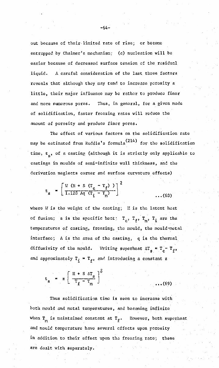
-64-
out because of their· limited rate of rise; or become
entrapped by Chalmer Y s mechanisrJ; (c) nucleation will be
easier because of decreased surface tension of the residual
liquid. A careful consideration of the last three factors
reveals that although they r.tay tend to increase porosity a
little, their major influence may be rather to produce finer
and more nuoerous pores. Thus, in general, for a given mode
of solidification, faster freezing rates will reduce the
amount of porosity and produce finer pores.
The effect of various factors on the solidification rate
may be estimated from Ruddle's formula(2l4) for the solidification
time~ ts' of a castine: (although it is strictly only applicable to
castings in moulds of semi-infinite \17011 thickness, ane the
derivation neglects corner and surface curvature effects)
t s [t-J (H + S (T
= 1.123 Aq (T ~ 1. ••• (63)
where tJ is the weight of the casting~ II is the latent heat
of fusion~ s is the specific heat~ Tc~ Tf , Tm' Ti arc the
temperatures of casting, freezing, the mould, the mould-netal
interfacc~ A is the area of the castin8; q is the theroal
diffusivity of the mould. Hriting superheat I::.T ... T - Tf , s c
and approximately Ti ... Tf , and introducing a constant z
t s = [ H + S I::.T l~
z ~s_ T
f - T
m ••• (69)
Thus solidification time is seen to increase with
both mould and metal temperatures, and becoming infinite
when T is maintained constant at Tf • m l!ouever, both superheat
and mould temperature have several effects upon rorosity
in addition to their effect upon th~ freezing ratc~ these
are dealt with separately.

-65-
4.6. ~uperheat, 6Ts '
Superheat is defined as the difference between the
casting temperature, Tc~ and the liquidu3 temperature, TL
(or freezing point, Tf ).
If a region of volune Vo of a castinr, becomes
entirely surround~d by perfectly rieid solid, then, according
to Simonik(29l), the volume V} of a resulting pore would be
(correcting a s~all omission)
••• (70)
where T is the average temperatur~ of the confined liquid j av
~L is the co~fficient of thermal expansion of the liquid.
The equation (10) predicts a greater volume of porosity for
higher values of T , and it is argued that T may be raised e.v av
by increasing the superheat. Jackson(2?2) also proposes
this idea. However the additionr..l porosity produced by higher
superheats by this mechanism can be safely neglected as the
following considerations ShO\>l: the difference (T - Tf ) is av
not likely to exceed about 10C(93), and ~L is very sma11 1 of
o (293) the order of 0.02% per C for carbon steels , compared
with ~t which may vary bett-leen about 3 and 12% depending upon
carbon content(294).
A high superheat may also provide the mould \,rith
considerable extra heat, resulting in an effectively higher
mould temperature (consieerin~ particularly investment
moulds) and 't..rill therefore be expected to make some change in
the temperature gradients and the solidification interval, 6t.
This point is taken up in detail in Section 8.
The effect of sup~rheat is further complicated by
its effect upon lic;,uid metal history. '0 d (264) ;Jog anov suggests
that at high temperatures nuclei for bubble formation are
taken into solution in the liquid metal so that the liquid
becomes rldeactivated J' • On the other hand~ if melting is

u u -01
>... Vi 7-82 z w o
u u -at
7-80
7-78
7-76
7-74
so
8-10
8-08
8-04
SO
STEEL XI (EI 572)
100 ISO 200 250 300
ALLOY ZhS 6
100 ISO 200 2.50 300 SUPERHEAT (OC)
The effect of mould temperature and superheat on air-poured turbine blade alloys Xl (Creep-resisting austenitic Cr-Ui steel) anq ZhS6 (creep-re iating Ni-b 8e alloy) by Bogdanov(L6~).
FIGURE 19A
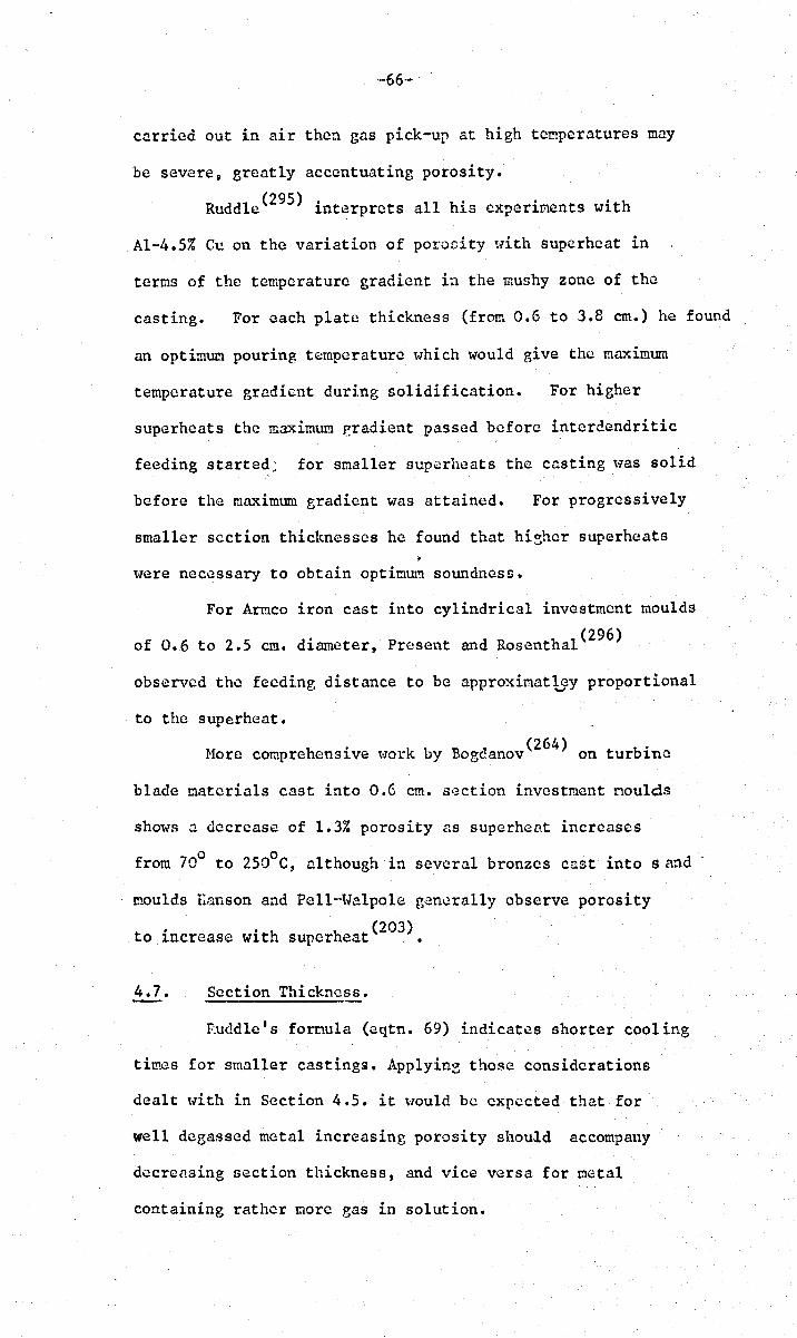
-66-
carried out in air then gas pick-up at high temperatures may
be severe, greatly accentuating porosity.
Ruddle(295) interprets all his experiments with
Al-4.5% Cu on the variation of por-oeity >;vith superheat in
terms of the temperature gradient in the mushy zone of the
casting. For each plate thickness (from 0.6 to 3.8 em.) he found
an optimum pouring temperature which would give the maximum
temperature gradient during solidification. For higher
superheats the maximum eradient passed before intercendritic
feeding started; for sI:laller superheats the casting \V'as solid
before the maximum gradient was attained. For progressively
smaller section thicknesses he found that hi~her superheats
* were necessary to obtain optimum soundness.
For Armco iron cast into cylindrical investment moulds
of 0.6 to 2.5 cm. diameter, Present and Rosenthal(296)
observed the feeding distance to be approximat\7y proportional
to the superheat.
(264) Hore comprehensive t-lork by Bogdanov on turbine
blade materials cast into 0.6 cm. section investment noulds
shows a decrease of 1.3% porosity as superheat increases
from 70° to 250oC, although in several bronzes cast into sand
moulds l~anson and Pcll··Walpole generally observe porosity
. . h h (203) to lncrease Wlt super eat •
4.7. Section Thickness.
Ruddle's fornula (eqtn. 69) indicates shorter cooling
times for smaller casting~. Applyine those considerations
dealt with in Section 4.5. it would be expected that for
well degassed metal increasing porosity should accompany
decrensing section thickness, and vice versa for metal
containing rather more gas in solution.
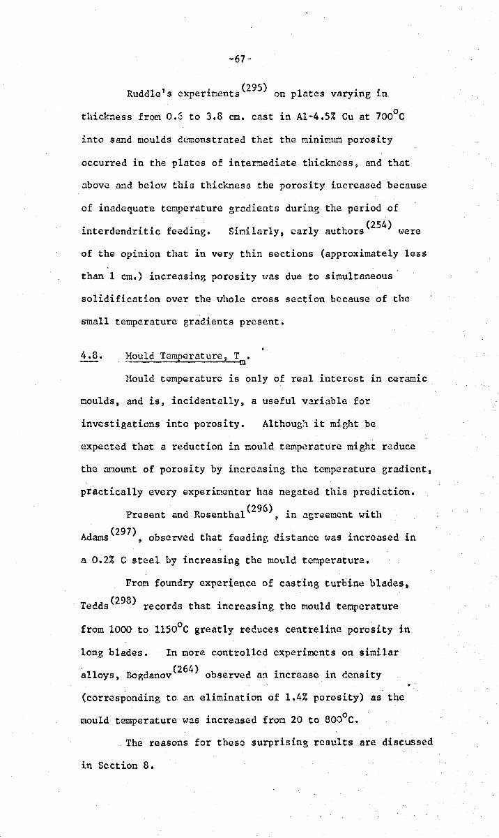
I ' . (295) I .. Rudd e s exper~ments on p ates vary~ng ~n
thickness from 0.6 to 3.8 ern. cast in AI-4.5% eu at 7000 e
into sand moulds demonstrated that the minimum porosity
occurred in the plates of intermediate thickness, and that
above and below this thickness the porosity increased because
of inadequate temperature gradients during the period of
interdendritic feeding. (254)
Similarly, early authors t.,ere
of the opinion that in very thin sections (approximately less
than 1 cm.) increasing porosity ~"as due to simultaneous
solidification over the uho1e cross section because of the
small temperature gradients present.
4.8. Nou1d Temperature, T • - ... ------::.--om
Hould temperature is only of real interest in ceramic
moulds, and is, incidentally, a useful variable for
investigations into porosity. Although it micht be
expected that a reduction in mould temperature might reduce
the amount of porosity by increasing the temperature gradient,
practically every experimenter has negated this prediction.
Present and Rosenthal(296) ~ in agreement with
Adams(297), observed that feeding distance was increased in
a 0.2% e steel by increasing the mould temperature.
From foundry experience of casting turbine blades,
Tedds(298) records that increasing the mould temperature
from 1000 to ll500 e greatly reduces centreline porosity in
long blades. In more controlled experiments on similar
, (264) alloys, Bogdanov observed an increase in censity
(corresponding to an elimination of 1.4% porosity) as the
mould temperature was increased from 20 to 8000 e.
The reasons for these surprising results are discussed
in Section 8.
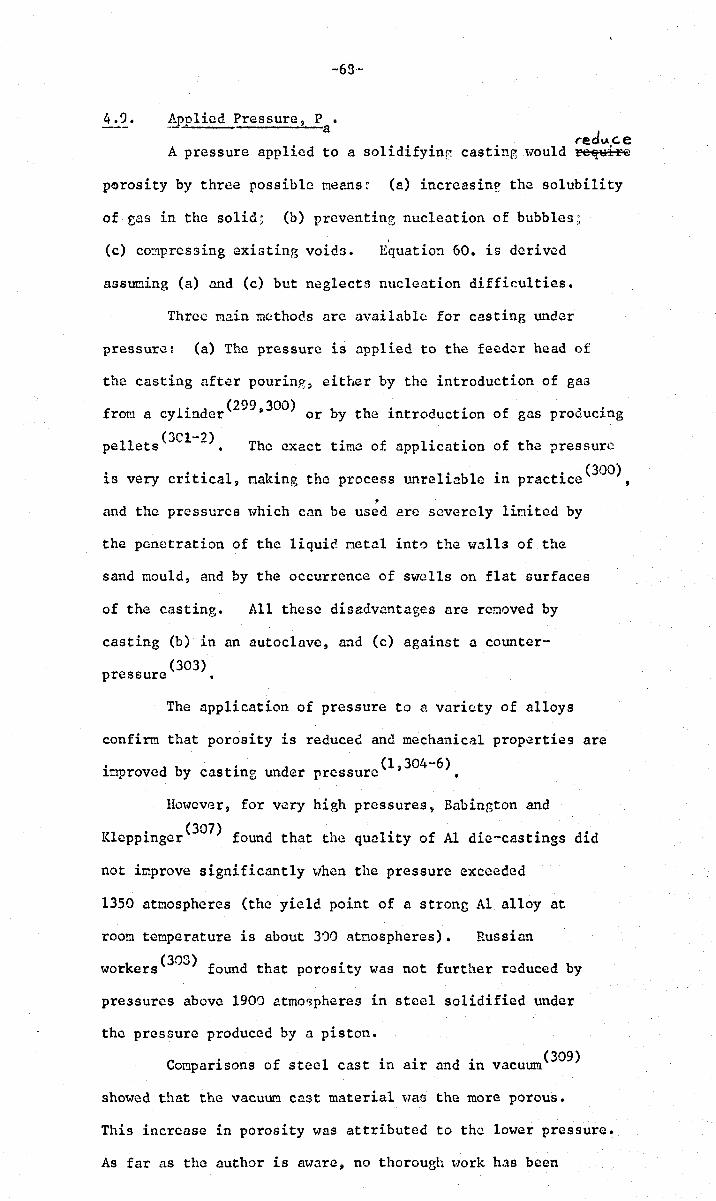
4.9.
-68--
Apolied Pressure, P • -- . a redlAc.e
A pressure applied to a solidifyinf casting would re~HiFe
porosity by three possible means: (a) increasin? the solubility
of eas in the solid; (b) preventing nucleation of bubbles ,;
(c) c03pressing existing voids. Equation 60. is derived
ass~ing (a) and (c) but neglects nucleation difficulties.
Three main methods arc available for casting under
pressure: (a) The pressure is applied to the feeder head of
the casting after pouring, either by the introduction of gas
f l ' d (299,300) b h' d 'f .' rom a cy ~n er or y t c ~ntro uctlon 0 gas prouuel.ng
11 t (3Cl-2) Th 'f I' . f th pe e s • e exact tlmo 0 app lcatlon 0 e pressure
is very critical, naking the process unreliable in practice (300) t
. and the pressures which cnn be used are severely linited by
the penetration of the liquid metal into the walls of the
sand mould, and by the occurrence of swells on flat surfaces
of the casting. All these disadvnntages are reooved by
casting (b) in an autoclave, a~d (c) against a counter
(303) pressure •
The application of pressure to a variety of alloys
confirm that porosity is reduced and mechanical properties are
improved by castinz under pressurc(l,304-6).
Ho\vever, for very high pressures, Babington and
Klcppinger(307) found that the quality of Al die~castings did
not improve significantly "I./hen the pressure exceeded
1350 atmospheres (the yield point of a strong Al alloy at
room temperature is about 300 atmospheres). Russian
k (303) • wor ers found that porosl.ty was not further reduced by
pressures above 1900 atmo~phere9 in steel solidified under
the pressure produced by a piston.
e . fl" d' (309) omparlsons 0 stee cast In alr an 1n vacuum
showed that the vacuUI!l cast material was the more porous.
This increase in porosity was attributed to the lower pressure.
As far as the author is a~;rare, no thorough ~"ork has been
-69-
published on the effC.!ct of lOHar pressures on porosity. This
is surprising since if porosity is 80verned nainly by the
expansion of gas bubbles then the inportant paraneter is the
number of tim~s the gas pressure may be increased. For instance
above atmospheric pressure a factor of about 103 increases in
pressure is attainable with good equipment, whereas from 1 micron
to 1 atr::.osphere is an increase in prC3:.;urc by a factor of 106 ,
which represents a useful and easily accessible r~nge of
pressures as a research tool. If however porosity is limited
by nucleation criteria, then absolute pressures are important,
so that 1 uicron may be effectively regarded as zero pressure,
and negative shrinkage pressures are pnssible. In vie\v of
the results of this experiment on :'3teel it seems likely that
porosity is not limited by nucleation difficulties, but is
limited only by growth considerations.
4.10. SU!-face Tension, t.
Bhattacharjya(286) conpared the numbers and sizes of
pores found in unidircctionally solidified 99.99% Al and
Al-3% BL The freezin~ characteristics of both were very
similar (AT f is only 40 C for the Bi alloy) but the residual
liquid in'the Al-Bi alloy was rich in Bi and therefore 10\1 in
aurface energy (the surface energies of Al and Bi are 860 and
380 ergs/cn2 approximately). Pores ,.;rere observed in the
Bi-rich interdcnclritic regions and ~lcre reduced in average
dianetcr by a factor 10, and correspondingly increased in
number per unit volune by a factor 103, for melts of similar
gas content. The resul ts lV'ere interpreted in tert:lS of
easier nucleation in liquids of 10H surface energy, and also
illustrate the eleMentary fact that fron the point of view
of nucleation the surface energy of the bulk liquid is
relatively uninportant, but the surface enerey of the highly
impure residual liquid is the critical parameter.
-70-
A further intcrestinz point is that up to about 1958
Bi was thought to b~ naturally slightly radioactive, eoitting
alpha particles on decay. This "laS because even the purest
forms of Bi commonly availa~le contained a snaIl &~ount of
highly radioactive impurity. This may be a contributinr, factor
to these results because of the enhanced nmlber of nucleation
opportunities corresponding to the higher density of energetic
alpha particles in t~e residual liquid.
4.11. Grain Size.
Liddiard and Bakcr(3l0) Guegest that a fine grain size
should improve mass feeding. The theoretical work by the
school at H.!. T. on the pressure reduction due to viscous flml1
(equations 27, 28) suggest that easier interdcndritic feeding
should also accompany decreasing grain size.
Cibula(311,312) found t~at porosity tended to increase
linearly with grain size for Al alloys and bronzes, but fOlli~d
a large scatter in his results. Calvert(313) confirms this
linear relation. Lago~vski t1.'1d Heier (233) 8r~atly reduced
porosity in Hg-Zu alloys with the.! use of Brain refiners.
However, the picture is not so clear cut, since recent
work on AI'-alloys in this Departoent (314) has shown I.l definite
increase in porosity with decreasing grain size. These
conflictine results could be due to an effect upon the 't.rldth
of the mushy zone, which is not an independent variable, and
in differences in gas content from one cast. to another.
A conparison of AI- and. Ug-alloys solidified under
similar conditions revealed that Ug-alloys contained the least
porosity. Liddiard and Baker(3l0) attribute the difference
not merely to grain size (their He;-a11oys were rather finer~
grained than the AI-alloys) but to dendrite morphology also.
Dendrites in Hg-aUoys (\-lith hexagonal crystal Syt:lIDctry) form
s1:1a11 rosettes with six 1:1ain branches in one plane. and little
In AI-alloys (t.;rith cubic
syonetry) the dendrite arns extend in six nutually perpendicular
directions, nnd by this ncans interlocking more nne so hindering
nass feeding, providinp: greater resistance to liquid feeding
and trnpping more liquid. Furthermore~ it is likely that
plate-like dendrites would p~ck more densely than three
dincnsional dendrites.
4.12. .,!::lper.
It ha3 been pointed out (315) that tlle funda'1lental reason
for tapering an originally parallcl castin~ is to achieve taper
in the liquid flow path. Brinson .:l.::ld Dumn(3l6) pioneered
a syoteoatic investigation into thb ~ffect of tapers varyine
o fron 4.8 to In on the c.cnG i ty of cast r. tee 1 plates. In
spite of sone scatter, their results show that n large taper
did not further increase the density nbovo that obtained \lith
the miniuum tnper. T!lcy .::tlso proved t~13t a non-linear t.:lper
could be onde r.1ore efficient th.::tn a str.::tight taper. Using
curve for the tapering of casting. Sullivan(315) proposes
a parabolic taper from thcoreticrtl con::Jiderations. Earlier
calculations an~ confirmatory experinents by this school (233)
show that a linear te.per of 1.7° is s\!ffici~nt 'to feed a
round, snne-cast bar of n pure metal to complete soundness.
E • d . b (318) h 'xperI.nents on lole ges cnst 1n ronze S 0\1
that step -w'cdgcs nrc more difficult to feed than othenvise
idcnticnl linear tvcdges. Thb observation F.ight be simply
l · ..> b 11" , . (229) h h f cxp aI.nc.... y Pe 1nI. S suggest10n t .It at a c angc 0
s~ction the feed metet! which is suckcd into the smaller
section ti1<'3.y carry -.lith it Golid material whic1:J. nay plug
the entranc.e. Later work (319) hOlvev("r casts doubt on the
general validity of this mechanism.
-72-
4.13. Vibration during Solidification.
In this largely unexplored fi~ld Jagaciak and Jon03(320)
and Dmitrovich and Butse1(321) have found that the D.pplication
. of vibration to soliC'.ifying castb.~s inproves their soundn~ss.
Although the full explanation of this result may be complex,
part of the cause may bc attributed to the finer I:licrostructurcs
produced.
4.14. Pouring Rate. , -
In extensive expcrinents on various bronzes, Hanson
and pell-Halpolc(203) found that porosity decreased with
slower pouring speeds. The effect is nost probably the
result of the high tct:1perature ercdients which maintain an
artificially snall vlidth of the mus~y zone.
-73-~
5. THE QUMITITATIVE HEASUP..EllENT OIl' POROSITY
Investigations into the phenomenon of microporosity have
been sovere1y h~pcred by the lack of a convenient and precise
method for its aSSCSGr.lent. Certain unusual techniques have
be..:!n suggested for th~ quantitntive nensurcment of porosity~ for
- (323"4) instance the usc of indentation hnrdness and neasurements
f h 1 d 1 . 1 ~ .. (323) o t erna an c ectrlcn cont.:uctlvlty • llm-vcver, six oain
techniques ~l1hich are used more generally arc examined be1m ...
5.1. Feeding Distance.
Feeding distance is defined as the 1en0th of casting
which can be fcd to perfect apparent soundness. This widely
used parameter can only be used for conparative purposes, ane!
can in no way be related to the quantity of porosity. In'
this respect the results nay be actually misleading, as the work
of vleins (325) suggests s since conventional X-ray techniques on
thick sections .:.re not sensitive to regions of fine, dispersed
microporositys \Jhich may therefore appear sound and increase the
apparent feeding distance.
5.2. Pressure Tichtncss.
Alternative methods of neasuring pressure tiehtnes~ are
described by Johnson (271), nnd Troj an auc. Flinn (326--7) •
Although the. pressure tightness of a complete casting t!l.:l.y be
tested, detailed investigation requires a thin slice of the
casting, bet~-1I.:len 0.03 and 0.64 cm. t!1ick, normally tnken fron
the thermal centre of the section. Althou!?;h the method is
rapid and easy it has 1aree disac..vantap-cs: it is subject to a
sampling error, and of necessity, only the interconnected
pores are assessed, which nay bear little relation to the total
porosity present.
-74-
5.3. Ultrasonics.
Abrahams and Lavender(329) have demonstrated that cicro-
porosity can be detected as a fine, IIgrass'-type" of oscilloscope
indication. Furthermore) Sr.!olen and Roscnthal(330) claio. thnt
ultrasonic attenuation appears to be ~ore sensitive than radio-
graphy in the detection of oicroporosity. They found n linear
relation betHeen density end the nunber of echoes, so that there
is sone hope of developing a ~ethod of assessing porosity in a
quantitative and non-destructive ~anner by this means.
5.4. ~.!.c:.tallography •
• \n evaluation of procedures in qu~titntive metallography
for voluoe--fraction analysis is 8i.Jen by Hilliard and Calm (331)
and Gladman ane Hoodhcad (332) • HOlvover, generally the met~lod
is arduous and the scatter in the results is high. Tho
unreliable element in the results derives not only fron the
expected standard deviation due to the point counting o.ethoc
(this con be reduced as far as C!esircc. by increasing the nunber
of points), but from the s~vere srn~pling error involved in
attemptine to estimate bulk quantities fron a single plane
section. Nevertheless, the tech'1ique provices additional
information on the distribution and morphology of the pores.
The rapidity and ease of obtaining results "(-lith the
quantitative television microscope could reduce the sampling
error since it would be feasible to exa~ine ma~y nore sections •
. This technique would then be a pO"t1Crful tool for the
quantitative investigation of porosity.
5.5. Radiographl.
In eeneral» X'-rays are not sensitivoa to porosity of
linear dimensions soaller than about 2% of the thickness of the
section. This is largely due to the blurring of the image
because of increasing average distance from the fil~ as the
-75-
section increases. Definition is further reducec by the
mottling of the image due to diffrnction effects associated
with large grain size of the . (333) d' ~. 4 ::;peClI:len ,an lon unnaC~llnec
castings by surface roughness. (334) (335) Trillat and Sharpe
have reviewed the tec~nique.
For the study of microporosity it is clc~r that
thinner sections having a smooth surf~ce finish must be used.
HallY workers have used 0.Oel2 cm. thick sections (10) for the
study of tdcroporosity, and Flemines (11) has observed pores
of only 3.5u in dianetcr by using a thickness of 0.005 cn.
r · B . . h 1 n. • n 1 A •• (12) nvestlogators at rltls Stce ~aDtln~s ~escarCl SSoclatlon
reco~cnd 0.05 em. thickness. Emwver, in a casting of about
1.0 cn. section there is a real p03sibility that such thin
sections might entirely miss the important regions of porosity.
To reduce this sampling error soncwhat, the author has used
specincns 0.125 em. thick and found that pores of lOu
diaoeter could still be cistinguishcd; tlle loss of detail
represented no loss of useful inforoation from the point of
view of a.quantitative assessment.
lm early attempt at quantitntivc evaluation of the
resulting raciographs ,..,as nade by Busk (336) • A later
rrleth::>c. crlploying point counting is I.~.cgcribed by Flemings (287) ,
and subsequently further inprovcd to give a direct value for
the percentage of porosity(337) •
5.6. pcnsit!.
Zevcral important disadvanta~es attend the usc of
density as a f,leasure of porosity. In comp1~x alloys the
proportions of the phases present nay change because of
differences in cooling rate, heat treatment, or working, so
that the density of the sound caterial is never known tlith
ccrt~linty • The results arc also affected by the presence
of inclusions and macropores. Finally, tbc methcd ia
-76-
rather insensitivo for conso alloys such as steels, so that
nany previous investigations using this method have failed
because experinental scatter has obscured real changes in
density due to the presence of porosity. A noteworthy
(333) exception is described by Ruddle •
Sone of these disacvantages nay be overcone as follows~
In nultiphase alloys a constant proportional relQ,tion bet~.,cen
the pho.scs present nay be attained between castings nade frein
the SarlC taclt (althounh other castin: conditions have been
vari~d) by appropriate annealing tr~atments. Duplicate
specinens reduce the chance of error due to occasional large
inclusions or macropores. The insensitivity of the nethod •
Call be ovcrcone by careful technique and accurate Heighinp,.
although for light alloys the senGitivity is in any case
considerably better than that for steels.
In order to c!etemine the L~ensity of the perfectly
sound alloy investieators often attenpt to renove the porosity
by rollinp- follow'ed by annealine. Emvever this nethocl
introduces porosity cue to the breaking up of inclusions.
A more accurate and reliable !!lethod is to estinate the
percentage porosity from a seninicroradio2raph of the most
sounc castin2 of a particular nelt, ~n1 relate this to the
densities of the remaining castings.
The density technique has the pr)\-lcrful advantages
of (i) being a non-cestructive methoc, (ii) eliminating
sampling crror for a given Spcci'.1cn j and (iii) yielclinf,
directly a quantitative value for the volume fraction
of porosity.
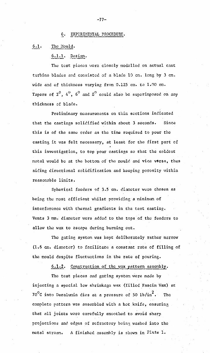
-77-
6. EXPERn1ENTAL PROCEDURE.
6.1. The Hould •
6.1.1. .Design.
The test pie.ccs \OTere closely modelled on actual cast
turbine blades ,-me. consisted of a blade 10 C1:1. long by 3 cm.
wide and of thickness varying from 0.125 cm. to 1.00 co.
Tapers of 2°, 4°, 60 and nO could also be supcrioposed on any
thickness of blade.
Prelioinary mcasureOG:nts on thin sections indicated
that the castings solidified within about 3 seconds. Since
this is of the same order as the time required to pour the
casting it l-ms felt necessary, at least for the first part of
this investigation, to top pour castings so that the colde.st
me.tal tv-ould be at the bottom of the could and vice versa, thus
aiding directional solidification and keeping porosity within
reasonable limits.
Spherical feeders of 3.5 cm. dianoter were chosen as
being the most efficient ,.,hilst providine a minimum of
interference with thermal gradients in the test casting.
Vents 3 rnm. diameter ,.,ere 8.dded to the tops of the feeders to
allow the ,.,nx to escape during burning out.
The gating system was kept deliberately rather narrow
(1.6 cm. diameter) to facilitate a constant rate of filling of
the could despite fluctuations in the rate of pouring.
6.1.2. Co~struction of the wax pattern assembly.
The test pieces and gating system m~re made by
injecting a special low shrinkage w~x (filled Fascim Wax) at
70°C into Duraluoin dies at a pressure of 50 lb/in2• The
complete pattern was assembled with a hot knife, ens urine
that all joints were carefully smoothed to avoid sharp
projections ane edges of refractory beinG washed into the
metal stream. A finished assembly is shown in Plate 1.
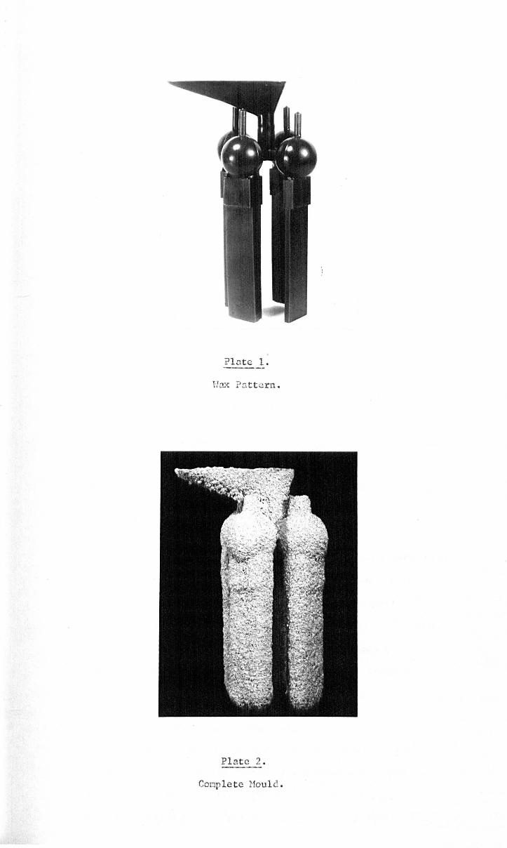
? l nt e 1 .
Hox ?ntt crn .
Pl at e 2 .
Comple t e Houl d .
-78-
6.1.3. Fornation of shell noulds.
The 'tvax pattern was dipped into a prinary solution
consisting of a colloidal silica bas~ containin2 a suspcnsicn
of 200 !'!lesh zircon (zirconium silicate). The \Jet pattern was
then suspended in a fluidiscd bect of 30-30 grade sillimanite
(aluniniu.':!. silicate) ann allowed to cry. A seconcary
coating of refractory was ~pplied by c!ip~ing the pattern into
a solution of ethyl silicate containin2 a suspension of
200 mesh dllimanite cnd ther:. it:ll:l.ersing it in e fluic!ised
bed of 16""30 erade nolochite (a heavily calcined alt.l!'.1iniurn.
The pattern 't'las then hunC in an atmosphere of
ar.:u:nonia for abcut t\>10 minutes w\1ich caused gelling of the
ethyl silicate, and finally left to c!ry in air for five
minutes to allaH excess runonia to evaporate. A further
five secondary coats ,.,rere applied, producing a shell
approxinately 0.6 cm. thick, and left to dry for twelve hours.
Care was taken to naintain the acidity of the
seconc:ary dip solution bc.t~.Jeen 2 tme. 3 pH to prevent premature
gelling of the solution.
6.1.4. De'tJ3xing and Fi rinG.'
The ooulds were c1elv:J .. 'ted by placing the!'!l in a furnace at
This s~ock heatin~ technique allo\Jcd the 'vax to
burn out ~;ithout cxpandine throur,hout its bulk resultin?, in
cracking of the shell, <~s happens in slm., hcatin~. The shell
was finally fired in air at noooe in an electrically he3tec
furn~ce for at least five minutes to remove all traces of
carbon.
G.2. Hould Prehcatinr; be fore Pouring.
" Hhen casting in air1 the mould was heated to 1100 C
in an clectric~lly heated furnace for 5 ninutes to remove as
ouch ~oisture as possible. The mould was then cool~d in
o the same furnace to a tcoperaturo a little above (about 20 C)

-79-
that required for pourinG. The mould was then rapidly
removed fron the furnace nne. the metal poured. The ter.tperature
loss involved in this op'-'!rntion lvas neasurcc and found not to
exceed 20°C even for the highest oou1d temperatures.
The same heating' cycle \Ja5 usee in vacuum~ but the
nou1d reoained inside the heating furnace during pouring thus
the tenperature control was rather bettor than that for the
air casting, and was ~stimated to be ~ SoC.
6.3. Me~ting and Casting.
Air oe1ting of steels was performed in a 40 lb.
induction tilting type furnace with lip pouring. A ranmed
basic lining was used. The melt was deoxidised with 0.1%
of a1uoiniun irnnediate1y before pouring. Six moulds could
be poured direct from the lip of the furnace in rapid
succcssLm thus ensuring sinUar pouring temperatures,
conposition and gas content. Finished castings were shot-
blasted to remove adhering refractory and oxide anc~. vacuur:l
o annealed at 950 C for 1 hour prior to taking density measurenents.
Aluniniun was melted in a 20 lb. Salamander crucible,
coated with an alunina wash, in a Horf,an gas-fired furnqce
and the temperature checked by noans of dipping alunina--
coated chromc1-alumel thernocoup1es. A temperature of
o 300 C was never exceeded in order to keep down the gns
content. The melt was degassed with proprietory degassing
c 0 tablets and r,'url3c ~t 750 C into moulds held at 200 C.
The pouring ladle was preheated by previously stirring the
melt: this procedure also reduced the temperature loss
during pouring to less than ZOC. In the first series of
casts, oxygen-free high-conductivity copper was acded in
increments of a length of a long rod which was also used to
stir the melt. A series of castings was produced of
various eu contents up to 17% Cu. T\lO repeat series were
-80-
!:lade up to lower en contents using tb.c remainder of the hi8h
copper alloy frofol t3e first melt as C'. teMper adc.ition.
Th~ procedure for the vacuurJ. meltin3 of high tenperature
alloys was to punp the chamber down to below IO~ pressure.
l1clting tms th'-!"t1 carried out in 1! 20 lb. induction tilting
unit in .'!n alumina crucible. T3c f.1ctal temperature tvas
brouGht to the required pouring temperature (~Soe) by means
of dipping silica she~thed Pt-Pt~~ thermocouples into the
1!!elt. Tt~ charge was then poured into moulds held in separate
heating furnaces on a rotatine platfam. Different pressuros
of areon could be introduced within about 10 seconds before
the pourine of each mould. Any excess !Jetal was poured off
into an ingot oould. The fini~hed C:l;;;tines were shot blasted
prior to testing.
6.4. Measurco~nt of Density.
was used
The well knovm Archimcclean formula for apparent density
P
U • '(,1Cir;ht in liouid L
PL • density of liqui~·(from tables)
Heichings ,-lera perforoed on an automatic balance and
were accurate to + 0.2 m(1'. "", Speciocns vlere weighed and the
zero re-checkecl repeatedly (not usually nore than three
times) until both the weisht readinf, ane the zero t·n2re constant.
The ~..rater temperature ,.;as read to I).osoe " .. hich t.ras on the
threshold of affecting the accuracy of the final result.
A scalI drift in temperature of the water of the ord~r of
o 1 C per day \18S obtained by usin3 a very large quantity of
,.rater - about ten litres - in a thicl:.~7alled p,lass vessi21.
-<11-
Kodak' wetting agent was aeded to the 'tlater in concentration
3 m1/1 which '-1as foune not to affect t"he density of water within
the accuracy of other measurenents. This minimised the adherence
of bubbles to the surface of specimens (which vlere always
closely inspected for bubbles on all sides before ~¥'eighinB) ane!
gave a constant meniscus uncle at the li~uid surface at the point
of entry of the w·ire. Occasional bubbles on the surface of tile
water v7hich attachee themselves to this Dcniscuil could chanr,e
the weight reading by 3 of,. or more.
The support wire was O.OOS CIn. diaracter molybdenUM,
carefully chosen from the batch so as to be quite st:l.Ooth to the
touch (for example it was foune that tungsten ,;ire ~.;rhcn rough, . affected tl1e neniscus shape in an erratic nanner catlsinf,
inconsistent reacinr,s).
The uei~hin3s in cdr tlcra perfectly un:unbieuous, but those
in liquic Here observed to change Uit!1 tine. A specinen
\J'eighing S:1Y 100 g. night incre~se in vleight by 2-3 mg. in
about five ninutes. P,~rt of this weight chanr,e \1.:13 due to the
adjustnent of the teo?eraturc of the speciMen to that of the
liquid but this c,Ju1c be tlinioiscd by ~l1o~linr. the specitlCns to
approximately equalise their tcmpcro.ture ,.lith that of the wctcr
by placinr, in the balance case adj D.ccnt to the \l.:'.ter container
for llbout an hour before taking the \lciphin3s in \later.
Other occnsiona1 increases in vleif;:ht couie not be attributed to
this cause and vJeN thour;ht to be the ~radual seepage of water
into internal pores. No increase in weight could be
attributed to the slight discolouration (representing a very
light rust film) of the steel specinens in the \mter.
The final ~ccurncy achieved depended' upon the vleight of the
s:,ecinen. For a specinon \Jeiehing 1 g. an accurecy of about
1 part in 400 can be expected: and for specinens weighing 10
and 100 g., 1 part in 4,000 and 40,000 respectively.

-82-
In order to dete~ine the percentage of pores froM the
density meRsure~ents it is necess~ry to evolunte the density of
the perf~ctly sound ~atcrial. For cerbon steels this was
atte~pted by celd rolling the speci~en to. about 757. reduction in
thickness, ann(!.:lling at 950°C for 1 hOt!r in V~CutJr.l to regain the
original '!uantitative re1.~tion bet'(vc:~n th,~ phases present, and
finally cete~ining the density. This method houcver gave
unsntisfactory results ,.]hich were ,~ttribut':lc! to. the opening ef
peres due to the bree.king up of inclusions, and in any case the
methed .. 7as inpossiblc to. apply to high tenper.:lture alloys which
cannot be het rolled. Hence fron a given cast the specinen
which sheved the highest density W.:l3 intensively examinee. by
netallegraphic and semi· .. r.:licroradioerepbic techniques in order to
obtain a reu.gh estimate of its % porosity (an accurate asseSStlent
was unnecessary - even if it were obtainable - since the quantity
~-ms very sna1l). Once the density p of the sound n.".terial hed s
been estinatcd, the Z porosity of ecch ·)f the other specimens ef
the saBe cast could be obtained
where p '''os the density of the casting of unknown porosity content.
For a steel specimen weighine 1 g. nnd contnining 1%
porosity the maximun linits ef error are! 1%: for specimens
of 10 8' ane 100 g. contoining the sane ~ount of porosity tho
corresponding naximun errors are respectively! 0.1% nnd 0.01%.
In practice the smo11est specimens employed in these
investigations w'eighted about 100 g. so that the accuracy was
always better than ~ 0.01%. These accuracies are impreved by
a factor of abeut 2.5 for Al and its alloys.
-33-
6.6. Reciographic Techniques.
The as-cast specimens of 0.2 cn. thickness were lightly
surface ground to produce a good finish. Gevort douh1e-
conted. D.2. filn was used ~1ith a 0.015 en. lead backing screen,
nnd wns placed in contr~ct "lith the specimen. The 'anodc"film
distance was 100 cn. and the exposurc'l.bout 20 minutes at
100 KV and 10 rna.
Alongi tudinal line COU11t ~·1A.S carried out on the resul ti.n~
raC!iographs to measure the total lenr,th of line which trnversec
porosity as a percentage of the tot,el1 lcnfth of the specimen.
The !! ain disndvantagc of this ncth:)G. of interpreting the
radiographs WS3 that n faint or dark i~a6e could occupy the
same leneth of the scanning line, but obviously correspond
to different porosity in depth. A r(;,)u~h al1ot-rance could be
onde for this by giving different tlciehts to it:lagcs of different
intensity. It would clearly be a useful refinement to neasurc
the ar(~a under a nicrodensitonetcr SC:.l.n~ S0 that fron sever:ll
scems an reasonable inteerntion of the total porosity could b(~
estiL1atci! • Nevertheless, t!.le sinple line count technique 't1:~S
extremely enoy and quick to perforn ,-:nd has yielded r,ood
compar~tivc results.
For sel;}i-r:licroradiography 0.125 en. thick specincns
~;rerc l"ilQchinec1 from the geometric centres of the cast specincns.
The surface finish resulted from careful machiuins: on a
precision surface grinder.
The sa.rnp1~ Has placec:Ln a light-tight envelope in
contact with the emulsion of a fine erain~d X-ray filn. A
sheet of plastic foao placed behind the film ensured good
contact between the filo nne sample.
Filtered Cobalt radiation is ideal for this work(337)
since absorption coefficients for the inclusions expected to
be present should be higher than the rJntrix, thus showing up

-84·~
lighter tho.n tho bi1ckf~rOund, and so clearly (Hstinguishnble
fron pores~ which ?,ive dark imnges. HOt'lover, to give
reasonable exposure times, unfiltered cobalt r:ldiation was used.
The sm:lple \]as placec. 25 CI'1. from the target of 1 square nm.
This geometry should give, nt w'orst~ a rosalution of the order
of 5).1. Exposures ,,<]er(~ 3 hours at 36 I:V and \1 mao
A nould "laS prepared as describec'. in Sections 6 .1. and
6.2. consistine of spheres of sizes 2, 1.5, 1.O~ 0.75, 0.5,
0.33, 0.25 inches run via very long narrow ingates of diar.:leters
0.25? 0.19, 0.13, 0.094, 0.063) 0.063 and 0.063 inches
respectively. The latter representee the soallcst diameter of . insate \lith which it was feasible to use without constnnt
breakngcs durin~ t~1C coating of the wax. Thus, as far as
possible, a constant geomctrl obtainee for all ttc s9heres.
They were mountee on a circular assembly as syr'lT!letric".llly as
possible to balance netal flow ane! hellt content ~.]ithin the
noule. The wax assembly ane the finished aould arc shown
in Pl~tes 3. and 4.
P.K.24. alloy 'vas induction heated to l6200
C in an aluoina
crucible in a vacuum of 1-5 microns. This tCr.:lperature "laS held
constant for 30 minutes in order to out gas the octal os far as
possible. During this tine the Mould ~"as he~ted to llOOoC for
5 ninutcs in the same vacul.1I!! char.:lber. This 'vas designed to drive
off as ouch .. .]ater vapour from the mould as possible. The r.tould
o was t~en cooled to 1000 C at which tenpcr~turc it was r.taintaincd
until the netal '>vas poured. The alloy was poured at l6200 C in
vacuun and allotvcd to cool to near room temperature before air
t-laS admitted into the chamber and the crlsting t"cnovcd.
The densities of the spheres were determined as described
previous ly cne: 801'.1i -microradiozraphs t\Tcre !'lade of 0.125 cr:t.
thick sections from the centres of the four sr:Hlllest spheres,
which were highest in (~cnsity.
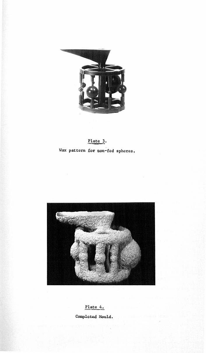
Plate 3.
Wax pattern for non-fed spheres,
Plate 4.
C~ete.d !-1ouLi.
'·35-
7. P.ESULTS.
A general observation CODrl0n to ex?erinents on all alloys
was that for sinilar castin3 conditions, soaller section
thicknesses Hero invariably associated with hi?,her porosity.
7.1. Effect of Su.£erhcat and Hould TcnpGr:1tur':..
For the 3 carbon steels (Fi!]:. 20.) increasing r.lculd
tenperature is seen to reeuce porosity~ whereas superheat
appears to have almost negligible effect.
The vacuun cast P.I~.24 alloy behoved rather differently
(Figs. 21. and 22.). ~t the lower pourin~ tenperatures porosity
showed a peak with increasin~ noule teMperature, but tendl~d to
• decrease at the higher pourinS tor-perature.
7.2. Effect of Co~osition on Porositl'
Each composition of steel reported above corresponJs to
a single cast~ so that comparisons between specinens of the
sane cast arc not inf1uencee by variations in composition,
particularly gas content. An a1ternativf.! presentation of these
results to investigate the effect of carbon content necessarily
involves conparisons ef different casts, rendering any
conclusions~ at best, only tentative. This caution is given
weight by a conparison of a 0.25% C steel cast into 0.75 em.
section ~oulcl at 300~C which giv~s porosities of 0.45%
(Fig. 20.) and 0.13% (Fig. 25.). This s~cond cast was
dcoxic1ised by about 5 tiraes the nomal addition of AI.
Fig. 23. ~'1aS constructcd~ nevertheless» but \vith0ut
recarc to the effect of superheat (ass~ed to be practically
negligible) and includes data from a east of electrolytic iron.
It sho~vs a prominent peak in p'Jrosity at about 0.7% C.
A rather cHffcrent a!,proaeh to the experiMental data
to7aS used in interpreting the AI-Cu results:
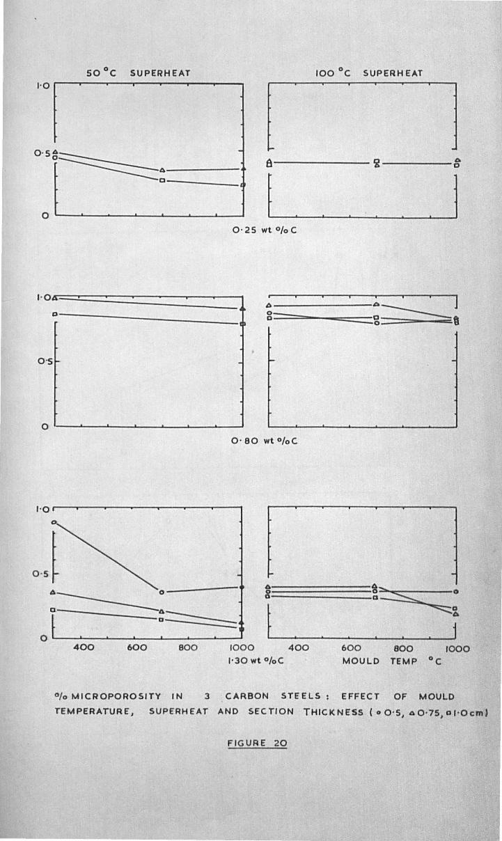
so °c SUPERHEAT 100°C SUPERH EAT 1'0 r---~-""'--"",---"""---'----'
O.S8~~ -
a c-o
t 1 .j
0
0'2Swt % C
I·Otr=.~==========J 0--__________________ _ b------------------~~ I ] 0_ _ _____
a _~= zl
0'5
o I--__ ~ __ ~ __ ~ __ ~ __ ~ __ ~ __ _J
O' 80 wt %C
A !~S;; ::;~
A 0 8
a==-----:::::::::___ t j
0 400 600 800 1000 400 600 800 1000
"30 wt %C MOULD TEMP °c
% MICROPOROSITY IN 3 CARBON STEELS: EFFECT OF MOULD
TEMPERATURE, SUPERHEAT AND SECTION THICKNESS ( 0 0-5, AO'75,o"Ocm)
FIGURE 20
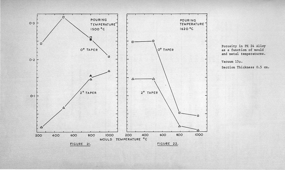
0 POURING l
f 0-3 t- / "'- T EM PERATURE
ISOO °c
0 • -I t- c ' 0 OOTAP~
a 0·2 r
0
~ 1 I A 6
0,1
200 400 600 800 1000 200 400 MOULD TEMPERATURE °c
FIGURE 21.
POURING TEMPERATURE
1620 0 C
0
600 BOO 1000
FIGURE 22.
Porosity in PK 24 Alloy as a function of mould and metal temperatures.
Vacuum l5lJ.
Section Thickness 0.5 em.
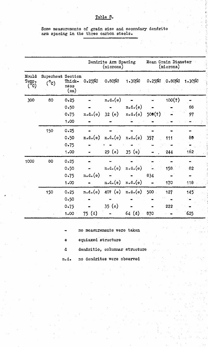
Mould Temp.
(oe)
300
1000
"
Table 8.
Some measurements of grain size and seoondary dendrite arm spacing in the three carbon steels.
Dendrite Arm s)acing Mean Grain Diameter (microns (microns)
Superheat Section (oe) Thick- 0.25%0 0.80100 1.30100 0.25100 0.80100 1.30100
ness (cm)
80 0.25 n.d.(e) 100(?)
0·50 n.d.(e) 88
0·75 n.d.(e) 32 (e) n.d.(e) 50e(?) 97 1.00
150 0.25
0.50 n.d. (e) n.d.(e) n.d.(e) 357 111 se 0.75 . -1.00 29 (e) 35 (e) 244 162
80 0.25
0~50 n.d.(e) n.d.(e) 158 82
0·75 n.d.(e) 834 1.00 n.d.(e) n.d.(e) 170 118
150 0.25 n.d.(e) 40? (e) n.d.(e) 500 127 145
0.50
0.75 35 (e) 222
1.00 75 (d) 64 (d) 870 625
no measurements were taken
e equiaxed structure
d dendritio, columnar structure
n.d. no dendrites were observed

/'0 A
,,- ...... .. I \ 8
0·9 I \-6-
/ \ 0
I ~ >- !\ ... I If)
/ 00'8 -a. \ 00-Ir / \ 0
Q. / \ ~ 0
/ \
0'7 / \
/ \ / \
/ \ / \
0-6 / \ / \
I \ , \
O·s I \ /
\ A
/ \ .&./ \ .- \ 0'4 -eGA .3. \ "9-• \ .. ' ... \ Iil ,
0·3 I \ , • \ / I
0 -0-\ 00- .J Q. I :> :l : \
0'2 z 0 wU I 0 :l t- 0 -t1r , ... 000 , U • Lu oog
I \I)
C"'l " - "lOr
0'1 O-s em oe-o-I
/ 0-75 /) A-cr
·te /·0 D • .0-
/
0 0-2 0'4 0·6 0-8 1-0 1-2 1-4
Wt % C
EFFECT OF COMPOSITION ON POROSITY IN IRON - CARBON ALLOYS
FIGURE' 23
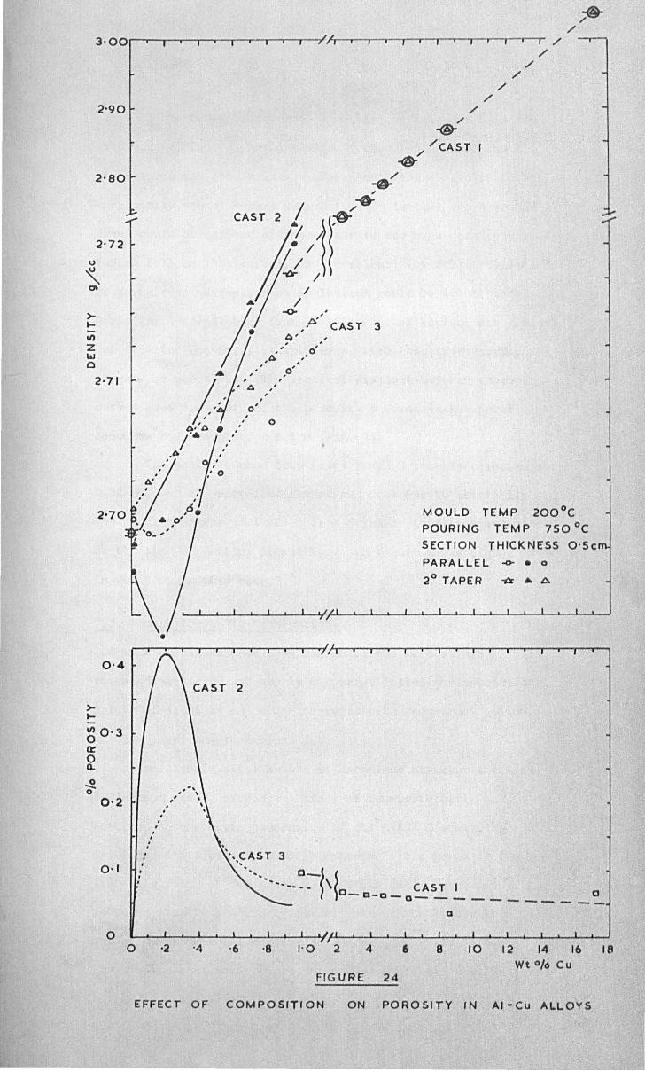
fo /
3·00~~~~'-~-r-r-r~-.~~,~~~~~~~~-r~-'~~r-~TI /
2'90
2'80
>.... \I)
Z l&J o
2'72
2·71
0'4
>-.... \I) 0'3 0 cr 0 Q.
~ 0
0·2
0·1
o
•
. , . , . , " , , , , ,
:
o
/ /
/ /
/ /
-®-/ / /CAST ..
-of
CAST 2 / ~ ... 3/)i
, 0' ,
/ /
-0- ,
,,~' CAS T 3
~' " , 0'
,A" ",
, , ,
o
,0' ,
". CAST 3
MOULD TEMP 200°C
POURING TEMP 750°C
SECTION THICI( NESS O'Se
PARA LLE L -0- • 0
2° TAPER ~ .. A
..... o_~ ~ •• ~------ \ CAST I
0_ D-D _ 0- _ _ _ . 0 --------o
1'0 2 4 6 8 10 12 14 16 18 Wt % Cu
FIG URE 24
EFFECT OF COMPOSITION ON POROSITY IN AI-Cu ALLOYS
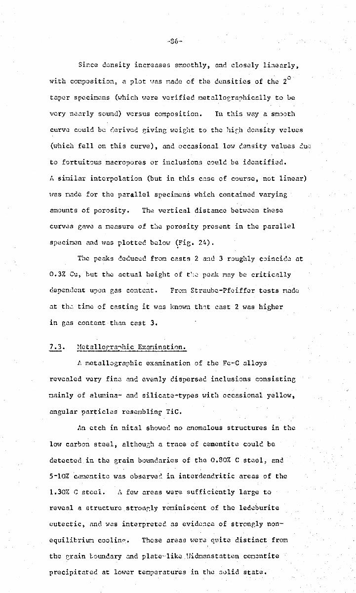
·-86-·
Si~ce dwnsity increases s~ooth1y, and closely 1inaar1y,
with composition~ .1 plot ~ms nade of the densities of the 2°
taper specimens (\17hich ~Jere verified metallo£ru?hicelly to Le
very nearly sound) versus composition. In thin '''ay a snooth
curve could be c;eriv(.!d ~iving weieht to the 11ifh density v.:11ueR
(~"hich fell on this curve), and occasional low density values due
to fortuitous macropores or inclusions could be identified.
A similar interpolation (but in this case of c0urne, not linear)
liaS Dnde for the parallel specimens ~vhich contained varying
a~ounts of porosity. The vertical distance between these
curves eave a ncasure of t~1e porosity present in the parallel
specimen nnd ''las plotted belm" ~Fie. 24).
The peaks c1educ·.;:c from casts 2 a~1d 3 roughly coincide at
0.3% eu, but the actual height of t':~ peek May be critically
dependent ur-H)l1 eas content. FroD Straube-Pfeiffer tests nade
at the title of casting it lYaS known th::t cast 2 was higher
in eas content than cast 3.
7.3. l1ctalloGra:,h~c E:cnnination.
Ie Metallographic examination of the Fe-'C alloys
revealed verJ fine nnd evenly dispersed inclusions consistine
mainly of alUlilina-w nne silicate-types tlith occasional yellow,
angular particles rcsc8blin~ TiC.
An etch in nital shOWCG no anomalous structures in the
low carbon steel, althou~h a trace of cementite coule be
detected in the grain boundaries of the 0.80% C steel, ane
5-10% cenentitc was observe~ in interdendritic areas of the
1.30% C steel. A few creas were sufficiently large to
reven1 a structure stroup,ly reminiscent of the 1edcburite
eutectic, and '.J.::!S interpretec as evidence of strongly non·-
equilibriun coolin~. These areas were quite distinct from
the crain touudary and plate-'like ~Jidt:lanst:ltten cementite
precipitated at lot%r temperatures in the nolid state.
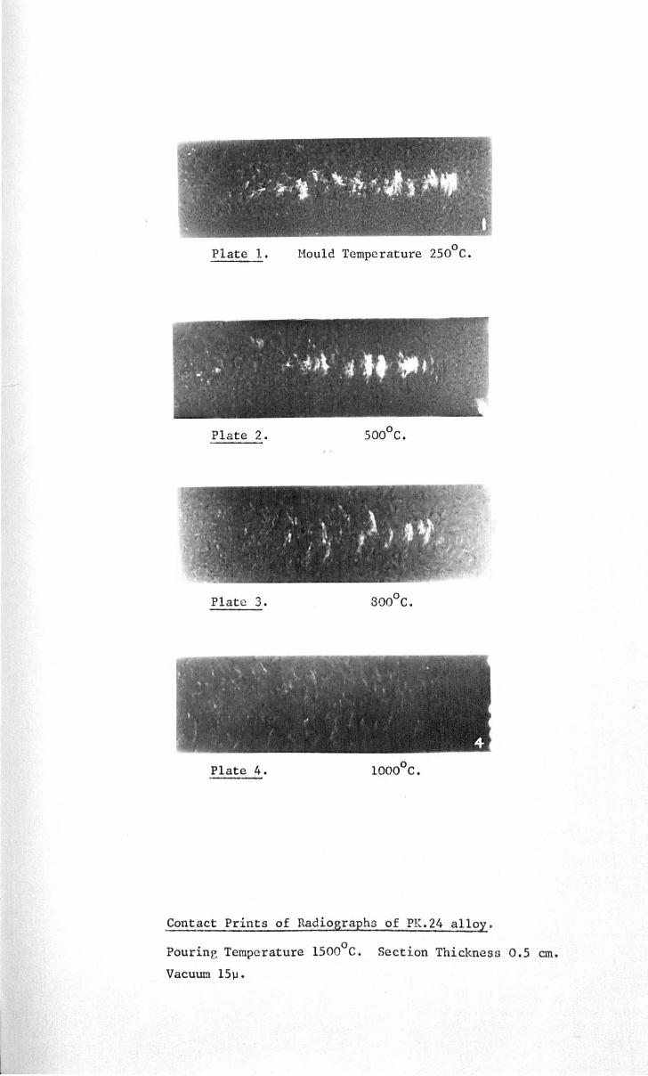
Plate 1.
Plate 2.
Plate 3.
Plate 4.
o Mould Temperature 250 C.
Contact Prints of P~diograph5 of PK.24 alloy.
Pouring Temperature l500oC. Section Thickness 0.5 cm.
Vacuum l5)..l.

Plate 5. ° Hould Temperature 270 c.
Plate 7. 800°C. (Da. ... ~8ecL F; /M)
Plate 3. 1000oC.
~ontact Prints of Radiographs of PK.24. Alloy.
Pouring Temperature 1620oC; Section
Thickness 0.5 cm ~ Vacuum 15~.

-37-
Heasuremcnts of grain size cnd dendrite ,'J:ntcinp:
relating tl) the steels are given in Table 8. E::tch result
represents a nean of at least 10 detcroinations on on~
polished section.
Hetallocr<lphic exc!,Zlinntion of the Al-Cu alloys rcvcalcc.
a stron~ly cored structure in the dcnc.rite3 even in the
spccincna of lowest copper content, an(: although fron the
equilibrioo. ciagran eutectic would not be G.xpectc;d until
5.7% Cu, above 1% Cu eutectic appeured first in trace anounts,
increasing to a practically continuous intcrdendritic file
at 4.77. Cu.
7 4 R " h' E ' t' •• -!::lGlograp lC ':1(.:1nln·'1 lone
Contcct prints of radiographs of 0.5 co. thick specicens
of P. K. 24 and X40 alloys are ShO\-ffi in P1ctes 3-5. It is
evident that at lo~ler Mould tenperatures porosity is
concentrated in nncroscoric form at the thermal centre of the
cnsting? whereas nt high t:lou1c tempcr.:ltures it is widely
dispersed and very fine. It is elsa just discernnb1e th<lt in
t!lis conc1ition the actu.:ll m.ount of porosity deng the
ccmtreline is very snall coopared t,j the region on eitherside.
These observstions nre er.::)hr.sisc(! and nadt:! qu.:mtitntive in the
lonei tudind line counts ShO\ID in Fir.:s. 29. and 30.
T:1O tendency for porosity to occur in l,~y(~rs is also
clear in ~any of these plotes.
7.5. Effect of Taper on Porosity.
The results for X40 ol1oy (melted in a 10 lb. inc.irect
arc furnace? and pourec directly fron the furnace into noules)
are givon in Fig. 26. A laree increase in soundn.:~ss was
obtained by superimposing a 20 tarer on t~e specimen, but
o little extra benefit is obtained by increasing the taper up to [I •

I S' ""'-t--- .-....-..--- . ~-.-. , ---- ! ;" , & •• -- "' t ' • 1
','.: f
J Fig. 25. EWEaI' OF TAPER AND SECTION THICKNE:3S ON POROSITY.
O.2S; C Steel 0
E 300 C Mould Temp.
0 1-2 . 1615 C Pouring Tempo
~ I_I l • Fully run speoimens
~ ~
I x Inoompletely run speoimens
1-0 L
·9
-8
·7 ~
I f ·6 ..
·5 • t
·4 - I !
-3 .. \ t 4
0-25 em 0-5 em 0-75 em SEetron \ Sec';on if
S e: ct;o n .2 • '\.
i t f '. f i _____. ""'i
ff -I .. t~ , I f ---'- -I
~------01. I ~ oJ 1-._
0° .2° 4° 0° 2° 4° d' 2° 4°
Taper
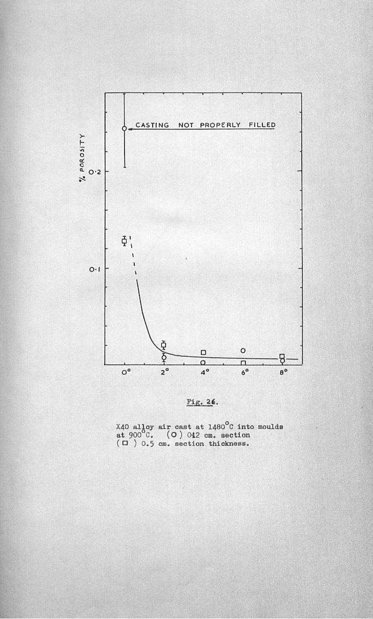
CAS TI NG NOT PROP E RLY FI LLED • >-t-Il)
0 a: 0 Cl. 0'2 ~
0·1
Fig. 2'. o X40 al~oy air cast at 1480 C into moulds
at 900 C. (0) 0·12 em. section (CJ ) 0.5 em. section thiokness.

>-~
\1)15 O' c! o 0..
.J!. o
1·0
0·5
o
+
+
o 10 20 30 40 50 0/0 AREA OF MOULD NOT FILLE D
POROSITY IN MIS. - RUN SPECIMENS OF 0.4cm
SECTION} AIR- CAST IN 0.3 0/oC STEEL AT "I'IO·C
INTO MOULDS AT 300°C.
FIG . 27
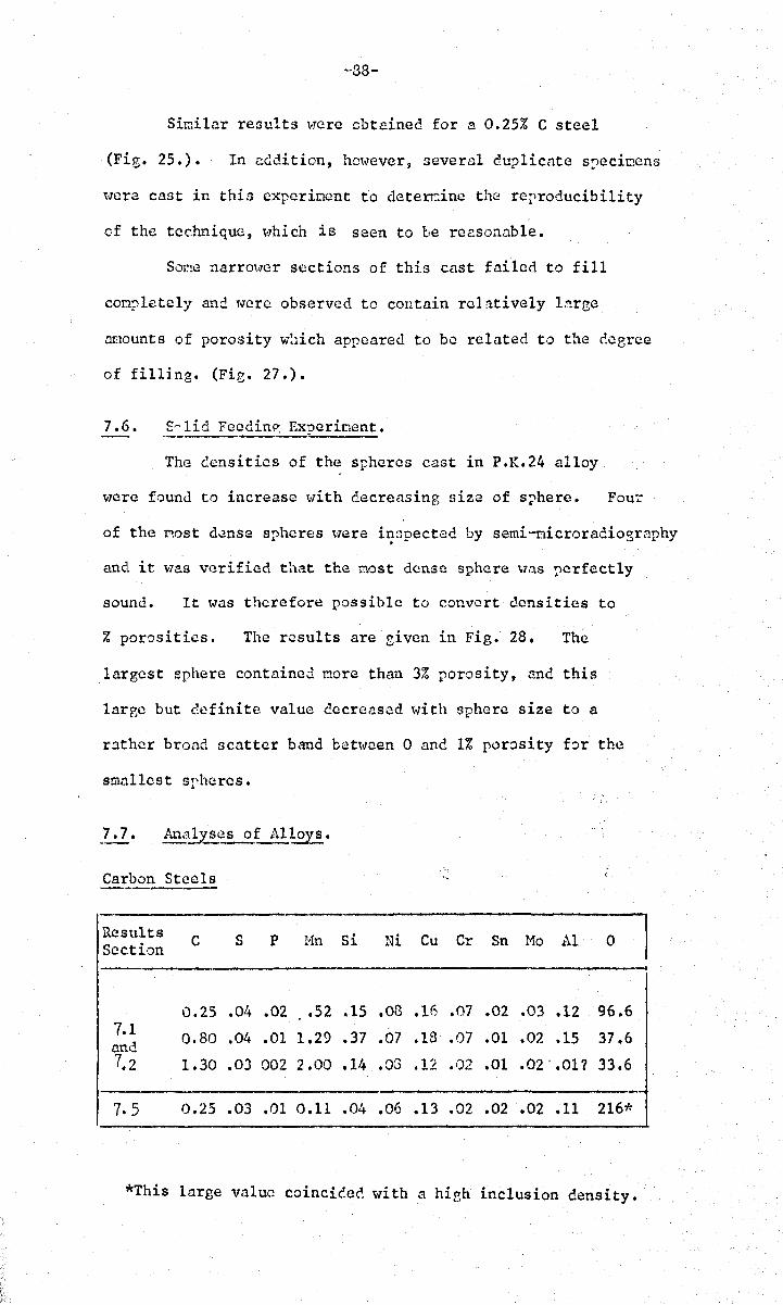
~88-
Similar results were obtained for a 0.25% C steel
(Fig. 25.). In addition, hmvever, several duplicate s,ecincns
\'l(~re cast in this experinent to deterc.ine the reproducibility
of the tec.hniquc, "lhich is seen to be reasonable.
SOl:le narrOT.Jcr sections of this cast failed to fill
conpletely and w'ere observed to contain relatively l.'1rge
at!lounts of porosity w!lich appeared to be related to the degree
of filling. (Fie. 27.).
7.6. s~ lid Fcedin~ Experinent.
The Gensities of the spheres cast in P.K.24 alloy
were found to increase \vith decreasing size of sphere. Four
of the ~ost dense spheres were i~3pected by semi-nicroradiography
and it v78S vGrified that the most dense sphere Wi,tS Ilerfect1y
sound. It was therefore possible to convert densities to
% porosities. The results are given in Fig. 28. The
largest sphere contained more than 3% porosity, nnd this
large but definite value decreased ,,,ith sphere size to a
rather broad scatter band bct,.]Cen 0 and 1% porosity for the
smallest srhcres.
Carbon Steels
Results Section
7.1 and 7.2
7.5
C
0.25
0.80
1.30
0.25
s P Hn Si
.04 .02 .52 .15
.04 .01 1.29 .37
.03 002 2.00 .14
.03 .01 0.11 .04
" ,
Ni Cu Cr Sn Mo Al o
.03 .16 .07 .02 .03 .12 96.6
.07 .13 .07 .01 .02 .15 37.6
.03 .12 .02 .01 .02' .Ol? 33.6
.06 .13 .02 .02 .02 .11 216*
*This large value coincic'.ec. ~-li th a high inclusion density.
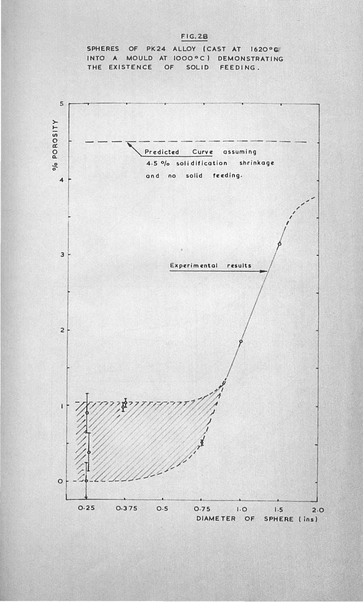
>... til o ex: o Q.
~ o
5
1 ..
3
2
o
FIG.2.8
SPHERES OF PK24 ALLOY (CAST AT 1620o ~
I NTO A MOULD AT 1000 0 C) DEMONSTRATI NG THE EXISTENCE OF SOLID FEEDING.
- - - '-;r=c:-c-::v-:=umin~--4 .5 % !.olidification shrinkage
and no solid feeding.
Experim ental results
I , " , '" ... ,
0·25 0·375 0 ·5 0 ·75 1. 0 1·5 2 .0 DIAME TER OF SPH ERE (ins)
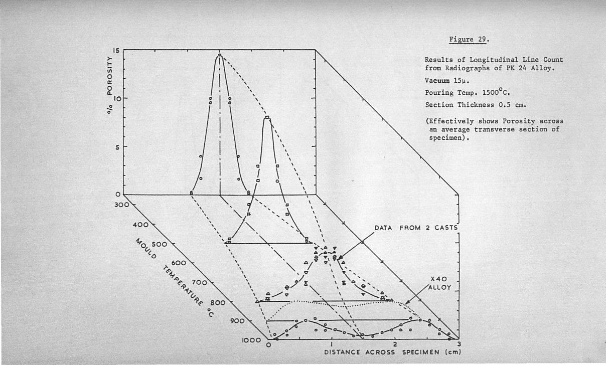
>I-\I)
o a: o 0..
~ o
IS
10
51-
t 0
/V
600 }-~
~A)<=- 700 ~ ~}-G-
"P<=-
,
a
I 0\ a - I
\ \
a \
\
\ \ \
\ \
\ \
, , \
.. Figure 29.
Results of Longitudinal Line Count from Radiographs of PK 24 Alloy.
Vacuum l5~.
Pouring Temp. l500oC.
Section Thickness 0.5 cm.
(Effectively shows Porosity across an average transverse section of specimen).
'" I "" \D \ \, J~ "" \, , " ~ \
, " \ ,.,: I... \
FROM 2 CASTS
, , ' \ • • ... ,6 "
\ '" A,,-6-.a \ ~ * :\ ,. '. " / \" \ ,0 \ ,,'"
'. / \ ,\',
\ ~/ " \ & ~"'" \ b,./"'V " \ ............ ACA .' ......., \ a' A \ •• , ....... ~ \ ......... iPV •••••
\ ... . ..... ,... .... .... ~ .... \ .. ... \ ,.~ \,' 0' \ 0 '. , ~O~" ( ;::;;-0-e. ; \ 0 0 : 0- ' ~'. -o~ 0 ~o ,O/",O O--.~--.-O O·
o C'
o I 2 3 DISTANCE ACROSS SPECIMEN (em)
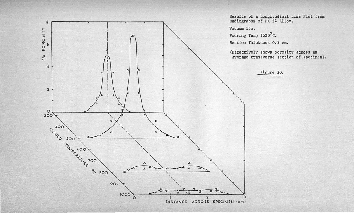
8
>-~
11\
o 0:6 o Q.
o -o
4
2
o.
o
o /
"\.
Results of a Longitudinal Line Plot from Radiographs of PK 24 Alloy.
Vacuum l5~.
Pouring Temp l620oC.
Section Thickness 0.5 cm.
(Effectively shows porosity ac~oss an average transverse section of specimen).
Figure 30.
SOO
>-.
D' "
a,.....=='""D " - a.......... p
~~ 600 .()~ ~ ~)-v 700
-?~ o C'
"-" , " A' A
/6----;:-·~~A_.-A~.::Io ~6 " ~
o
'\, "'-,
.. or.,. .--.,... 9_9_"- V v-.,. .. ,. .. . q ...
123 DISTANCE ACROSS SPECIMEN (em)
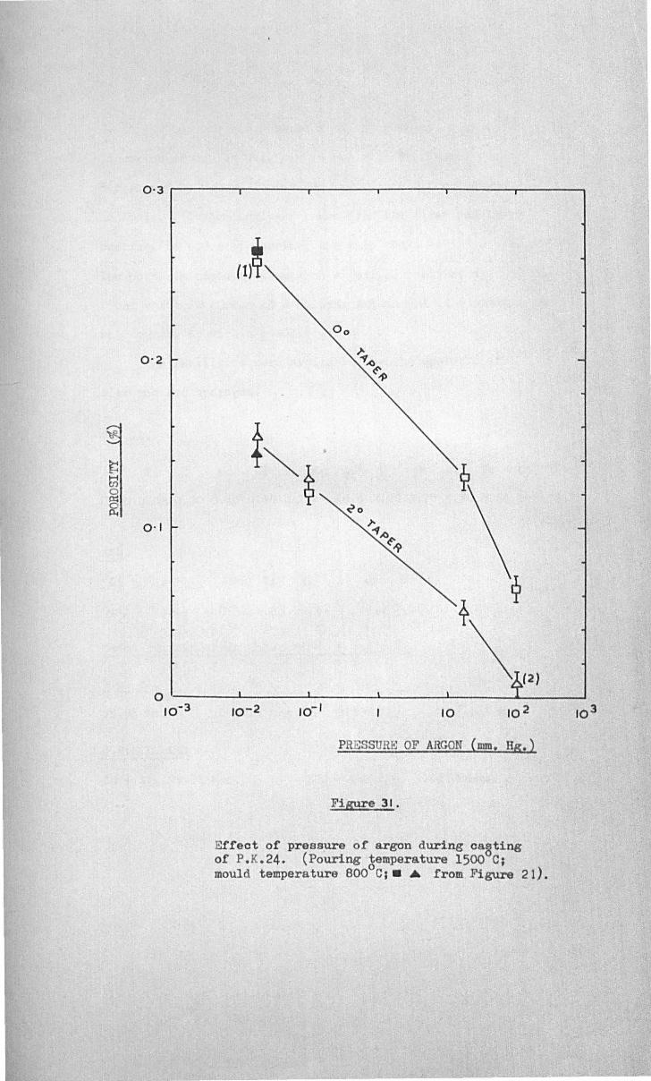
~ H en 0 @5 p.
0·3 r-------~------,_------_r------~------_,------~
0·1
0 10-3
(1)~
; ~
~o
r.., .o~
-9
i ~
\ (2 )
10-2 10- 1 10 10 2
PRESSURE OF ARGON {rom! HS t )
Fi&'lre 31.
Effeot of pressure of argon during oasting of P.K.24. (Pouring temperature 1500 Cj mould temperature 800oC;. .. from Figure 21).
10 3
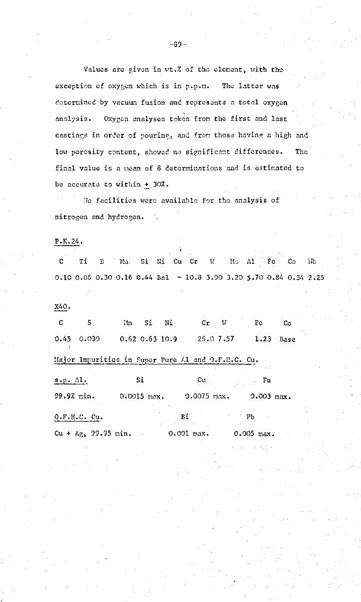
-·39-
Values arc giv',:m in \-!t.% of the; c1enent, Hith the
exception of oxygen which is in p.p.n. Tho latter was
ccterwinec by vacuun fusion ane represents a total oxygen \
analysis. Oxye~n analyses taken fron the first and last
castin~s in oreer of pourin~, an(~ fron thos,;! havin~ a high and
10\'1 porosity content, showed n,) sienific.:1::1t differences. The
final value in a Doan of 8 detcrninntiol1s cnd is estimated to
be accurate to within + 30%.
Ho fncilities were available for the analysis of
nitrogen and hydrocen.
P.K.24.
C Ti B Hn. 8i Ni Cu Cr !:to 11.1 Fe Co lfu
0.10 0.05 0.30 0.16 0.44 Bal - 10.8 3.90 3.20 5.70 0.84 0.34 2.25
X40.
C 5 an Si Ni Cr lJ Fe Co
0.45 0.030 0.62 0.63 10.9 25.0 7.S7 1.23 Base
11ajor Im!.?uri~ic[l in Super Pure iU and O.F.H.C. Cu. -
s.p. AI. 5i Cu Fe
99.9% r.lin. 0.0015 r.1ax. 0.0075 nnx • 0.003 :r.lmc.
O.F.H.C. Cu. Ri Pb
Cu + Ag, 99.95 min. 0.001 :r.lax. 0.005 max.
-90-
3. DISCUSSION OF RESULTS.
l3.l.?olid Feccinrr'
The problcn of soliel feedins i3 considered first since
the results and conclusions have bearinp. upon the interpretation
of all the othcr experincnts.
The spheres of .:1.11 sizes uere unfed to a,proxinately th~
S(JnC extent becausc the ,,,hole castinz geomet.ry \,](13 kept as ncar
~likc as possible) 50 that the usual asstlt!ption ,",ould be that
each would contain the srume fraction of porosity~ ancl this
would b~ close to the value a, the solicificaticn contraction,
wll:i.ch is probably about 4.5 .!. 1.0% for P.K.24 alloy (Fir. 28).
If, however, a negative prezsurc builds up in these
cO!lfincc volumes of liquid (Section 3.5.), then the exterior
solid s:tell oust b~ contracted by the rec1.'.ccd internal
press\!ru (the exterior atnosphcric pressure would normally assi:.t
this proccl3s; in the present \-lork however vacuum conditions
'tlCre used) at first elastically 5 and subsequently plastically
as the ceformation proceees. Tho exte~t of this 'solid
feecHnz' (Le. the. indra~"in0 of solie materic.l to cO!!l!?ensate
for t!1C contraction cue to solidification) depending upon ttY'O
main factors (0) the mechanical strensth of the solid, and
(b) the value of the necativ~ pressure.
require further discussion •
These factors
J:he exterior shell of th,; 1ar8or sphere'3 will be
relatively cool bufore solidification has far ndvanc~d to~ards
its centr.~. Thus the solid will be relatively strone and
better able to resist the internal suction effect. The
nceative pressure lvill therefore increase more rapidly, and
soon exceed a certain critical level for nucleation,
resultin3 in the creation of a pore. The pore "{-lill rapidly
expand to equilibriun size, dispellinz the internal stress
~'9l-
and arresting solid fcedine, ane thereafter ~rO\" s1m11y to
compensate for shrinkap,e until solidification is complete.
In a small sphcre~ the tempGrature of thc exterior shell will
have fallen very little by the tiMe solidification is complete
at its centres so that plastic £10\>1 is facilitated for a
longer tiMe in relation to the solicification time of the
sphere. By this means) the neeati ve pressure is preventcc
from reachin~ hieh values even at n late staec in solidificntion,
so that there is a possibility that in the absence of a
sufficiently f,ood nucleation site a pore \>1ill not occur.
The castin13 will be sound C'.espitc alnost perfectly non-fcc.
conditions of solidification. •
The problen of pore nucleation sites can be discussed
statistically. If ,,,1.3 arbi tarily a3S\.l.r:le that there are about
10 nuclei/coco then statistically the snaIl spheres of volume
0.1 c.c., ~lil1 contain either a few nuclei, or none
the larger spheres, of volUMe 50 c.c., \-1i11 contain in the
region of 500 nuclei. This menus th~t the negative pressure
vlhich can be reached in the larg(;!r spheres ~"i 11 be lini ted by
the presence of large n~bers of nuclei which will pronate
nucleation at low hydrostatic tensions. As the sphere size
decreases, the probability of the sphcr~ contnining no
fnvourab1c nucleation sites increases, so that the n~gative
pressure is allowed to reach the hi8h values necessary for
efficient soli~ fcedinp,.
The results sho~m in Fia. 28. reveal the expected
scatter in the quantity of porosity in the smaller srheres.
Of the three smallest spheres only one was sound, indicating
a nuclei density close to that assuacd. Thcactual
inclusion density of the alloy usc~ is norc nearly an order
of maenitude r:rcater than this, so that it seens probable
that most inclusions are not favourable sites for pore
nucleation, 'tvhich is to be expected from considerations in
S~ctions 2.3. and 1.4.
-:)2,.
The results of this experi~cnt ca~not b~ accounted for
by assunine any other fcec1,inf.:, ncchanisM then that of solic1
feedint:;. This seems to be therefore a stronr, justification
of the correctness ane n~cessity for accertine this concept
as an important feedinr, process.
The results are, hom~ver, m:1cr..ab1e to ,!in alternative
interpretation in the sense that it is coolinz rate rather
than siZE: 'Jf sphere which is important in affecting solid
feeding in this particular experiMent: if all the spheres cast
vlere icc'L1tical in size then a sl01" coolinp, rate, resultinr;
in a hich,~r tcoperature and cO:J.3cql1ently hi ther plasticity in
the solid shell, tJOuld give a norc dcn3C c9stinry. Thereforc~
in conditions where liquid rer.ions are unfed, and yet are
required to be p~rfectly sound, a SlOH coolin;:; rate is
required, in aerceMent with the quantitative predictions in
Section 3.5.
8.2. EffccJ:._o} Superheat JJ.T s-,_,_llnd !Iou1.:' Temperature Tn'
In the experiocnts on ?K.24. alloy bcrcasine super
heat reduces porosity s onm..rh at I but for the carbon steels
superheat is remarkable for its complete inability to influence
porosity except in the hirh cnrb0n sted ,,'lere its influence
changes from increasin~ to decrcC!sin~ porcsity depcndin~ on the
section thickness. The 1nttcr observations !!l~y be attributed
to the rather snal1 difference in superheats ~i'hich ll7.'lS
perhaps insufficient to clearly distine,uish nny tendencics.
Because of the snall difference in scperheats~ tbe
areas of the incompletely filled castings of another melt
(FiG' 27.) ::trc of considerable interest siIlcc it is !,>robable
that the areas of the castin;,=:s arc a ncasurl.1 of superheats
close to zero) and since th~ poro3ity in these castinp,s is very
high~ \J'C may tentntivcly concluce that increesino.: 3uperheat
increasc~ soundness in carbon steels.
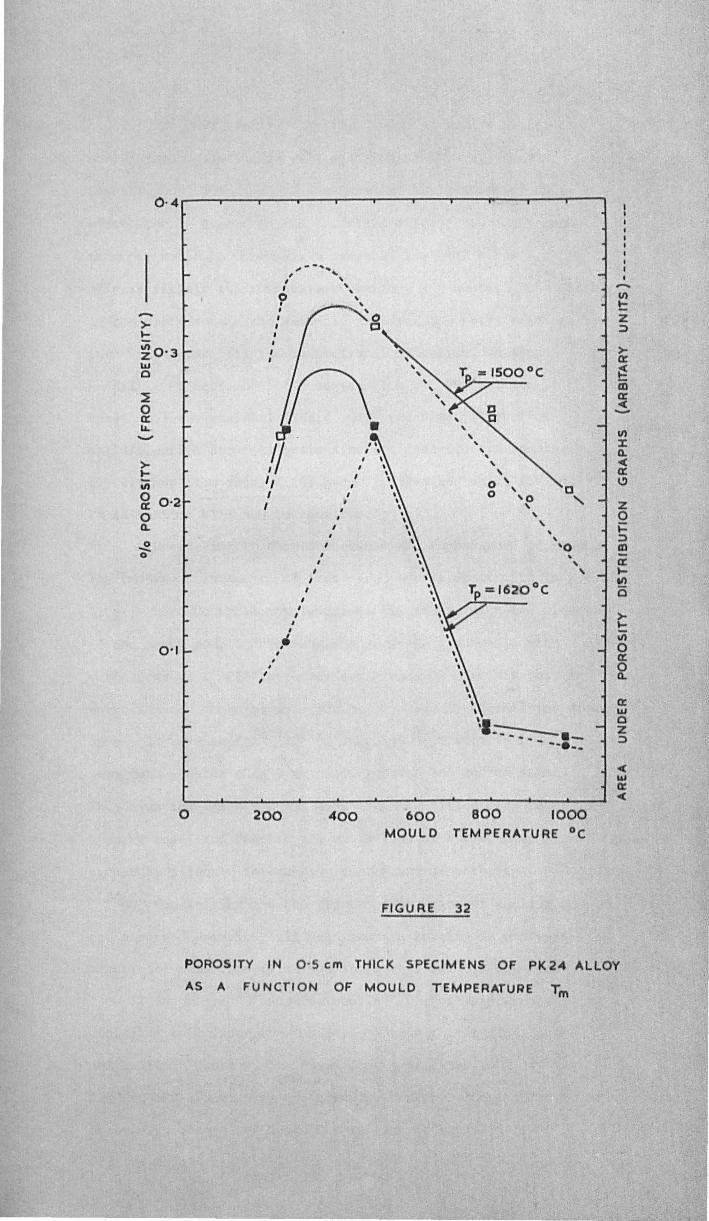
->-)0-
11) ZO·3 LIJ o
>-!: 11)
~ 0·2 o Q.
0·1
, , ,
,,- -' .. , ... I ' , ' ~ , , ,
n. d' . II /\ '/ I '.
II " I ,
I ;
I , , ,
I
, I
I , , ,. I
I
I
, ,
, , , , ,
, \ , , ,
, , , o " 0 o '0 , " , , , ,
'0 . , ,
\'1.::-:::--. _ - --e_.
->ct
~ m ct -< -V)
l: Q. -< ct C)
Z o i= ;:) m ct ttl)
(5
>)0-
iii o a: ~ ct LIJ o Z ;:)
o 200 400 600 MOULD
800 1000 TEMPERATURE °c
FIGURE 32
POROSITY IN 0 ·5 em THICK SPECIMENS OF PK24 ALLOY
AS A FUNCTI O N OF MOULD TEMPERATURE Tm
-93-
The observation of Cccreasing por'Jsity vJith increa~dn,::.
nould teoperature a~recs \1c11 '>lith the results of other
investi ~ators (Section ll.7.) and yet no explanation of this
effect can be tracec in the technic~l literature. Any such
would be necessarily 30r.lC1;'J'h:lt involved since T T!1
effects firstly the tenperature gradient and hence Ls the 'vieth
of tne pasty zone ~ and secon(~ly th~ frcezinr:; rate, Hhich in
turn influences (1) the mode of solidification, whether
dendritic or equia:~\;!d; (2) se?ree,~tion nnc the surfnce
tension of the residual liquic, (3) tho time interval of
solidificntil)n ~t; (4) grain siz(-: ane c.::m·~rite ann s;?Glcing:;
(5) viscous £lOti rates:~ (6) burst fce(Hn~ a:ld solid feoding.
These factors will nO\l be considered.~
!)ecreasing T should increaoe the tCT!1)?crnture p,rnclicnt. m
The important influence of this parameter is cealt with in dct~il
later; here we shall nerely aSSOGB its effect upon the width
of the pasty zone L. The maximun cradicnt attninable with
.. f T ·11 b bI 1 ~(\°c'L' h·· vnr1at1ons o· ,,Jl pro a y not cxcccc .J" . t~II'IS1nCe t 1S lS m
a;?proxiMGltcly the T!1axirll.nn ?,ra(~ient obSClrvcd in solidifyine stcI;1
in a cold snnc. oould (229,274), which t\Toul:~ result in L
very much greater than I crn. even for tho low carbon steel.
Thus ev~n the lar2cst noule used would be filled with metal in
a pasty con~ition ~espite all variations of T , so that L • .. m
cannot be a factor inf1uencin~ the amount of porosity.
Considcrin~ now the affect of th~ rate of coolin~ on
th~ observed porosity: if dencrite am spacing is a direct
measure of this rate (Fler.lines ShOHS that this is true for
Al-4.5% Cu alloys (38) nnd for steels (237) for very l\Tidely
differing solidification conditions) thon the lir.lited data
available in Table 3. indicates that a decrease in T from t!1 o
1000 to 300 C increases the freezin~ rate by almost a factor
of 2. Pro cedinG now to an exanination of the various
factors dependent on this rate=
-94-
Host cnstines s.Jlirlifiec. in nn equinxcd nanner, and
although the few tllat revealed colunnar structure tended to
have rather hie:h.er anounts of poro:Jity, t.he de,ta is too
linited to dnm fim conclusions. Tll(; ~ffect dOCJ not
appear to be large.
The 0n~lJ.ter oasc of nuclec.tiotl of pores cluJ to th~
scrrezation of inpurities and inclusions into the residual
li~uid is not likely to be greatly affected by the relatively
S1:1<111 chan?;c.'3 in solic.ification rate introi!.uced in these
experiments, since all conditions w'ill .:lppraxinate well to
perfect non-equilibrium, -described in Section 4.4. Furt~1crmorc ,
it is probable that t~lC alloys arc Guffid~nt1y inpure as to
• be little affected by further concentration of i!:lpuri tics.
hs Tn increases, the consequent rccluction in freozin0
rate should caus(~ flt, qrain size, ane. cCD.dritc am spacin~
to increas·,;: poros i ty. Exparinentally however, porosity in
eenarel was observed to c.ccrc.!1se with increasinz Tm so that
these factors arc either uninportal1t in these cxPQrioents,
or arc outwei~hcd by oth~r influences. In c.ddition,
(2"'6) 3h~ttacharjya' s ~'1ork v dcnonstr.2t~s that porosity is
larg';,lly inc.cpcndent cf flt when the pas content i:; snaIl)
which is probably true of practically all of the alloys
used since tbe bveh of porosity \wre Vwry 13Mall.
The inportance of the follm-linR; two factor'3 is not
ensy to assess: both ",·rould tend to reduce porosity "it:l
increasing T ~ (.~) Th~ pressure c.iffcrential across the l':!
pasty zone woule! be lolv(~rec! during sloHer freczin~ because
of the slower movenent of the liquid durine; il.'lti.!reoncritic
feccin~, i'! .. "1d (b) burst f~cdin~~ t-lhich acts Gi~ilarly since
the neta1 \>Iill remain in a non~ plasdc condition for a
longer ti!'2c ltlith hi~hcr values of Tm (a1 thourh it is possible
that the lower shrink:!(jc pressures wrdc~l nccoo!"nny slow
-95-
solidification may in any case reduce the likelihood of a burst).
Neither of these IP.echanisras can be dismissed on independent
r:;rounds but both are thousht to make a relatively small
contribution to porosity in these experi~ents because of
ar;?'l.mcnts based upon the distribution of porosity 1:vhich are
discussed in the fol1ovin~ para'?,raphs.
Thus far in this search for a co rent explanation of the
effects of pourin~ and mould temperatures on porosity, out of
11 possible influencint mechani3Ds, by a series of elimination
lye are left with 2 parameters llhich appear to be of prime
importance~ temperature ~radients ruld solid feeding.
FL~s. 29. and 30 can be explained. qualitatively very satisfactorily
aSGurlin;: only the opcrntion of these tHO factors~
As mould temperature increa3es the temperature eradients
become less favourable so that porosity is no lon~cr
concentrated alonp the centreline (Fips. 29. and 30.) but is
dispersed over the wnolc castinr,: the base of th(~ porosity
distribution curvc widens. This may be stated conversely for
as Tm d.:!crcascs the increase" chillinp: pom~r of the o01.!ld
produces n prop:ressively thicker soune. outer rcp;ion of t!le
castinp:. Thus \lith 10,' T values the porosity is initially soall m
(Firr. 32.) correspondin::l' to a chill<3d structure, and increases
with increase in T • m
Solid fecdin? is practically inoperative with cold metal
but starts to become important <It hither tem~cratures, actin2
in opposition to the temperatura rradi(mts. The overall
density mcasurencnts reveal that solid feedinl". rather more than
bdanccs the effect of the unfnvourable r,radicnts at hi~h
temperatures, so that the total porosity falls a~ain above
The important feedin~ mechanism at .hi~h temperatures is
identified ns bcinr solid feedin~ because of the occurr~ncc
of the central dip in the porosity c.istribution (Firs. 29. and 30).
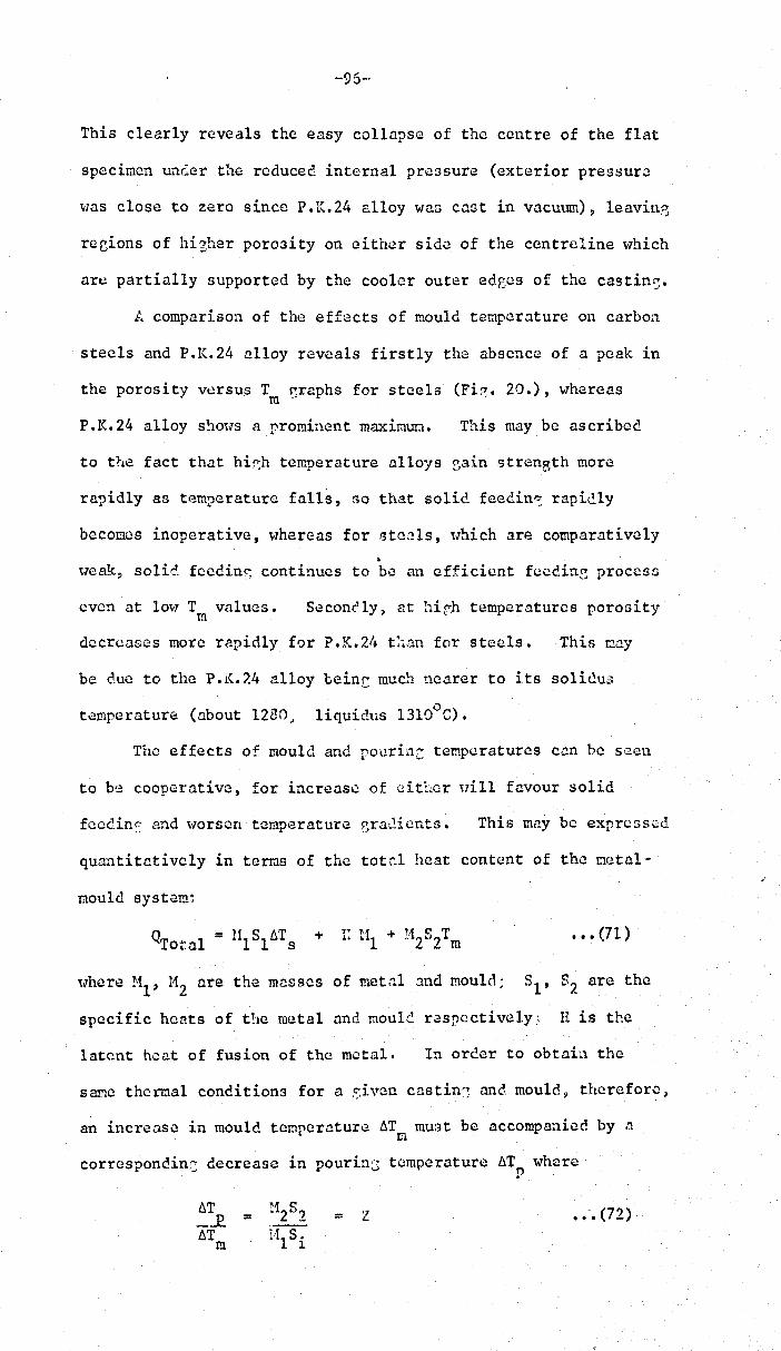
-96-
This clearly reveals the easy collapse of the centre of the flat
specimen under the reduced internal pressure (exterior pressure
~las close to zero since P.K.24 alloy was cast in vacuum), leavin~
recions of hizher porosity on either side of the centreline which
are partially supported by the cooler outer edrocs of the castin~.
L comparison of the effects of mould temperature on carbon
steels and P.K.24 alloy reveals firstly the absence of a peak in
the porosity versus Tm ~raphs for steels (Fi~. 20.), whereas
P. K. 24 alloy S3m.JS a promincnt maximum. This may be ascribed
to the fact that hi~h temperature alloys ~ain strength more
rapidly as temperature falls, so that solid feedin~ rapicly
becomes inoperative, whereas for steels, tlhich are comparatively
• ~"eak, solid feedinc: continues to be an efficient fecdin~ proccsf.l
even at lO~l T valucs. m
Seconfly, at hir;h temperatures porosity
decreases more rapidly for P.K.2/+ t:.an for steels. This may
be clue to the P. K. 24 alloy coint much nearer to its soliclu,,1
temperature (about 1230; liquidus 13laoe).
The effects of mould and rourin: temperatures can he sl~cn
to be cooperative, for increase of either tlill favour solid
fccdins and ,.,orsen tcmpI:;rature ~ra,.!ients. This may be expressed
quantitD.tivcly in tems of the tot~l heat content of the mc;tal-
mould systam:
••• (71)
,,,here ~il' 112 are the masses of metal and mould; Sl' S2 are the
specific heats of t!1e metal and mouL~ r.3spcctively:: H is the
latent heat of fusion of the metal. In oreer to obtain the
same thermal conditions for a sivcm castin'3 ane moulrl~ therefore,
an increase in mould tcmperD.ture ~T must be accompanied by a m
corresponcin2; decrease in pourinc temperature 6T where p
~T _..l? ~T
m
= = '1 '-' • •• (72)
-97-
where Z is a constant. For the 0.5 em. s3ction c·lstin~:~ the
ceramic could hac! a thermal capacity about t\·dce thnt of the
steel or hieh temperature alloy~ 50 that Z works out to
2 + 1 for t~is system.
The relatively small effect of superheat is emphasiJcd
by applyin::; equation ( 71) to a typical ferrous alloy, '"ith
moule temperature at lOOOoC and superheat 2000 C, the relatiwl
contributions to the total heat of the system from the mould~
latent heat, nnd superh~at are respectively about 21" 7 <1.nd
2 K calori~s ~ the latter represcntin(: less than 7% of the
total hQat available. These coasidcration.s help to understnn~
the small effect of supcr'hGat, p~!ticu1arly in the experiments
on carbon steels.
The noticeably lar0cr effect of superheat on P.K.24
alloy coulc1 be due to other effects ,']hich are difficult to
evaluate, particularly the possibility of certain efficient
pore nuclei bein3 taken into solution at hir,hcr temperatures (264) •
8.3. Effcc.t of S:~ction Thickness.
Trie results for all matcriala studied cl<~arly 8ho\-1 that
thinner sections are less sound than thicker ones. The
causes for this can be sou~ht in terms of (a) the rate of
solidification~ and (b) the oriGin of the porosity:
(a) Thicker sections will freeze at slower rates than
thick.ar sections. Ruddle's equation (63) in fact predicts
a parabolic relation betueen the solidification time ane the
mass of a castine-:, and this is confirmed reasonably 'vell by
tha mcasurc.!I:lents of eendri te arm spacin~ (Table 8.).
As in Section 8.2., the solidification interval 6t,
the ;,;;rain size and the dendrite arm spacin.:: should all
lead to a recuction in porosity as the section thickness
decreases. This is contrary to observations so these
factors either are not operative, or are outweiched by
-98-
other factors. Similarly, soliJ feedin~ ou~ht to increase
in effectiveness as section thickness decreases because
solidification will be completed while the exterior of the
casting ,..-ill still be relatively hot, and. therefore sufficiently "
weak to aHo\-1 solid fl..\edin~~, ane bccc..usc of the earlier
impinsinr-; of the! plastic zones on the free surface of the
castin:> both of '''hich would tend to k(~cp the hydrostatic
tension in the trapped lic;.uid region beloH t~1at required for
the nucleation of a pore. These qualitative arf-uments are
cons idered quanti tati va 1y in Section 3.5. Thu~ solid feedin3
cannot explain the experimental cata; furthermore, in very
thin sections of only a fC\-l Grain diameters or less in ~lidth ~
the concept of imprisoned liquid rc0ions becomes less plausible.
(b) The rate at \v11ic11 feedinr; liquid can !1C delivered
to resions of a castine at a late stage in solidification
is in proportion to the mnnber of availllble flow channels per
unit arCH, and therefore must be in approxim.1te proportion
to the ;3cction thickness. lIo\TQvcr, the rl..\quiremcnts for the
rate of f~edins do not decrease in this linear fashion as
section thickness dccreas~s, but arc expected to increase
rapidly b-:.:cause solicification occ.urs (0 simultaneously
t~row:hout the vo1une of the c~stins because of low
teopcrature ~radicnts? and (ii) very rnpidlybecause of th~
small amount of heD.t to be extr~cte(l. (equation 63).
f.s solicificction nears coopletioil, thGrefore, feedinG
conGitions become very difficult in thin sections, ane
hydrootatic tension beeins to increase. At this sta;;i.l
intcrdendritic or Lurst feceins from the direction of the
feeder b{~comes less feasible, but the transverse pressure
eradient may suck interdendriticliquid m..-ay from the
surface of the casting~ or if a Round, outer skin exists f
may caus~ this to rupture at a weak point, allowin?, the
in£ress of air.

Thus it seems likely thut the mechanism of fornation of
porosity changes with section size; as very narro\/ sections
a.re appro.:lchcd the mechanisIJ chanscs fron nucleotion-and-
growth in the interior of a liquic··solid mJ.ss, to the non'·
nucle.eticn process of liquid draina'~e 8t..JC:Y from .1 free surface.
This rnechanim!l will probably operate under rather small pressure
gradients between the exterior and interior of the castin3, so
that pores will form and p,row bef.)re the pressure differential
has rouched the larscr values necessary for efficient feedinG
by other nethods: interdcndritic (irOla the feeder), burst or
solid feedinG. This moce of pore formation TJ'ould be predict~d
to yield, therefore, higher levels of porosity than thet
produc\.!d by the nucleation process ~ in agreement \dth
observations.
The operation of such a process is evic!ent:" from the
appearance of cast s?ecinens of: 0.25 and 0.125 cm. thickness
(particul:lrly tho incompletely filled castins:;s, Figs. 25,-27)
where surface pores arc sCen to disapI'ear i:.ltO a labyrinth of
internal passa~cs. Also) vlhen t:-.c castinJjs are submereed durinC
density determinations their woir:ht i5 observed to increase
continuously as the pores gradually fill t-lith liquic.
~.4. ~ffect of .Composition.
It has oft(!n been assll.rnoc that incrensin~ the cquilibriun
freczine, ran0c ~Tf of an alloy increases its tendency towards
gre.'J.ter porosity b2ct~.U3i;) of the increased difficulties of feedinc
throu,sh the more extensive pasty 'zone. The results for
Fc-C alloys i~ Fie. 23. are therefore surprisinE~ since in3tead
of the expected continuous increase of porosity vlith carbon
content, a definite m~xioum occurs at about 0.7% C.
These observations Dlay cenuine1y represent the influence
of differences in carbon content, although thero is the
possibility that the t:esults nay be hCElvily influenced by
-100"
differences in ~as content. ,An attempt ~TaS made to assess
this possibility enp10ying the relations listed in Table 3.
The equilibriun partial pressures of the ~ases within a bubble
t.,rere calculated for the solidus tenperatt;res of each of the
steels. The total oxygen analyaes were used in these
calculations» so that rather hieher pressures t-lere deduced since
most of this oXYfen ~l1as chemically bound in inclusions: only the
oxygen renaining in solution \\Ta3 available for pore formation.
In the absence of analYi3es for n2
and H2 their effect ,,,as
estimated by assuming t!1e reasonably hieh concentrations of
3 0.01 vTt.% N2 and 10 cm /100 g. 1;2 (using conventional units).
The total eas pressures for the O.25~ O.SO and 1.307. C steuls
Vlork out to be 1.3, 1.3 and 2.9 atI!!ospilcres (ncglectine the
enhancement of these figures by seeregation effects, which would
increase them 411 by about the same factor). Taking these )
results a3 they stand, the ma.'{imum i.n the porosity-composition
curve cannot be explainec by differences in zas content.
The fet-] results available in Table 3. indicate that
th.=.: porosity maximum at 0.7% C ca::. neither be explaiu"c! by
changes in dendrite arm spacin~ noc erain size. Sinilarly,
no substantial effect can be attribut,~d to the decrease of
surface tension with carbon content since most investigators find
th'l'S to b l' 'bi (73,75~8/~f343,344) e nee 19l e •
(293) Values nre quoted for the contraction during
solidification, a» whic:l indicates a maximum at 0.7% C.
Unfortunately these results are based upon very early data which
do not appear to be reliable, particularly in th~ light of more
recent refined experiments by Vertman et. a1. (294) which show
an approximately linear decrease in a from 11.5% to 2.0% as the
carbon content increas~s frOM 0.15% to 2.')%.
A more plausible theory to explain the existence of the
maximun is baled upon considerations of the non-equilibrium
conditions during freezing.

-'101-
Conditions intermediate between true equilibrium and
non-equilibrium as defined in Section 4.4. could give rise to
o a maximum in frcezin?, range 6Tf of about 300 C at 0.7% C as
indicated in Fig. 13. This would correspond, of course, to
eq~ivalent maxima in difficulty of feeding, and in the amount
of final porosity.
There remains the possibility that the presence of
eutectic liquid under conditions of non-equilibrium freezing may
be causing the fall in porosity above 0.7% C according to
Scheuer's theory outlined in Section 4.4. Evidence of some
eutectic liquid was observed oetallographically in the
1.30% C steel, but the compositions of th~ steels were too •
widely spaced to draw firm conclusions.
Thus a closely spaced series of AI-Cu alloys up to
17% Cu was cast, and the peak in porosity determined to be at
0.3% Cu. Although the equilibrium limit of solid solubility
is 5.6% Cu, the second phase CuAI2 existed as a practically
continuous interdcndritic film at 4% Cu, and decreased to
trace quantities only at about 1% Cu. At 0.3% Cu no CuA1 2
could be Gctected although clear evidencG of non--equilibriun.
solidification 'v~l.3 provided by the heavily cored dendri tos.
It seems reasonable to conclud~, therefore, that the
porosity maxima observed in the Fe-C "'.ne Al--Cu systems (and
noted by other investigators for other systems ·A Section 4 .! •• )
arc the direct result of a ma.,,<imt.rm in the freezing ranee
composition relation e.s a consequence of non-equilibrium freezing_
8.5. .Ef~~ o.f Te_per.
Brinson ~~d Duma(3l6) observed that the critical taper
(assuming th.~t such exists) required to reduce porosity to
o low levels was belol.] 5 (the amallest angle investigated).
Tlie present series of investieatiouR lovers the estirn.:1te of
the critical taper to belou 20, '-lhich corroborntcs \ve11 l-lith
-102-
Halters(233) prediction of 1.70 calculated for a skin freezing
metal in a cylindrical sand mould~ and implies that despite
the undoubted preatar co~plexity of the moce of solidification
of the 0.25% C steel, the exterior taper imposes a similar
taper on the aggregate of the flow paths for the residual
liquid.
A further implication is that the formulae based upon
the viscous £10\7 of feeding liquid through the dendrite mesh
are fundnmentally correct.
8.6. Effect of Pressure.
The comparatively large reduction in porosity observed
experimentally (Fig. 31.) due ,to the rather small (absolute)
increase in pressures which vlas less than only 1 atmosphere,
infers that pore formation is easy,; imd must therefore occur
either by a non'~nucleation or anon -clasnical nucleation
mechanism. For instance to suppress classical pore
nucleation by gas in the interior of a complex inclusion, which
is the least strineent classical oondition (Section 2.3.3')j
an applied pressure of at least 200 atmospheres would be
rcquired.
Since nucleation is easy i t!Hm the quantity of porosity
is~ therefore, governec by grouth. Clearly, a gas bubble will
d 105. . 1 h . d ! expan to t~mes ~t3 vo ume as t c pressure ~9 acreascc,
from 1 atmosphere to 10~ pressure. T~is is also predicted
approximately by equation 60. Nevertheless, the quantity of
porosity in successive cas tines only decreases by a factor of
about 10 as the Ar pressure inside the vacuum chamber is
raised. This means that the growth of porosity must be
controlled by other effects in addition to th~J applied
pressure, ,md which are not allm'ed for in equation 60.
These may include~

(a) Equation 60 neglects the effects of shrinkage,
This is likely to be important, particularly since th~
contribution of gns to pore. ermlth is probably st:mll as a result
of remelting vacuum"-m:;;ltcd stock under V:lCU1.l1!l. The applied
pressure will add directly to the Bas pressure ~~d shrinkage
pressure, as indicated in equation 1. In th~ furthest regions
of th~ pasty zone of thn castine Ps may greatly oJtweigh other
pressures so that P and P become negligible and equation 60 .:t g
irrcl.cvent.
(b) The already advanced £rmvth of the solid may
mechanically liMit the expansion of a gas bubLle.
(c) There tlay be porosity prc::;cnt in the castine which
• is separate from the easily formed varicty~ and which is
nucleatud only ~lith difficulty, So that its formation is
comparatively unaffected by the small increase in absolute pressure.
3.7. On the Origin of ~ayGr Porosity.
Early authors (339-341) assUIr1.cd that pores resulted from
thermal contraction and \lere formed in the solid state in a
manner analogous to hot toarine. Baker(310,342) effectively
proves that pores for~m at a late stage in freezing; his theory
is rather better stated by Cibula(312) ~Jho arr.ues th~t after
mass feeding is arrested, further shrinkcge imposes tensile
stresses on t:1C continuous solid network which tears
perpendicularly to the stresJ? i.e. parallel to the isotherms.
If these tears are not healed by the inflow of residu.:l.I liquid
then layers of ?orosity result.
Bakcr(22J) attempted to test w~cther microporosity was
the result of thermal contraction by castinE test pieces in a
mould which "tlas desi~;ned to accentuate hot tearing tendenci(~s.
!iovlever 9 no sicnificant increase in porosity was observed.
The negative result of Daker's critical experiment is
substantiated by Cibula's observations(312) that grain
-104-
refinement promotes layer porosity but decreaseD the tendency
(278) towards hot tearinS I and lat~r t:lat AI-4.5% eu alloy ht':.s
little tendency to'V':lrds microporosity but comrn.only hot tears.
ExperiMents by Lagowski and Heier (283) on r'ig-Zn alloys
covering the runge of Zn contents from 0 to 307. Zn shm ... clearly
that the maxima for the incidence of hot tearing and micro-
porosity are Hell s(!paratcd~ occurring at 1% and about 6% Zn
respectively. Furthermore, the thermal contraction curve has
its maximum at 1% Zn indicating that hot tearing is associated
with contraction in the solid state, ::tnd not ~dth microporosity.
All these observations are substantiated by the
elementary consideration that th,a thermal contr.:l.ction of the
whole castine is likely to produce (if anything) a compressive
stress on the internal dendrite mesh because of the larger fall
in temperature of the exterior skin compared to the interior.
In materials of hieh thermal conductivity~ houever$ Such as
Ct: and lig:ht alloys, the tCr:lperaturc differential bctlleen the
interior and exterior is in a!1y cane 1i.kcly to be negligible,
producinr, no stress differential.
A new explanation of the origin of l~yer porosity is
therefore required, and n tentative moclol is proposed and
outlined balou. It is based not upon thermal contraction as
the fundaf.lcntal drivine force, but upon the contraction on
solidification.
If l.Te aSSUl"'le Fleminrs formula (equation 27) for the
prcssure differ~ntial across t:1C Mushy zone, and substitutins
their rch.tion (230) for the radius of the flOH channels as a
function of time
••• ( 73)
then we obtain the pressure differential as a function of time
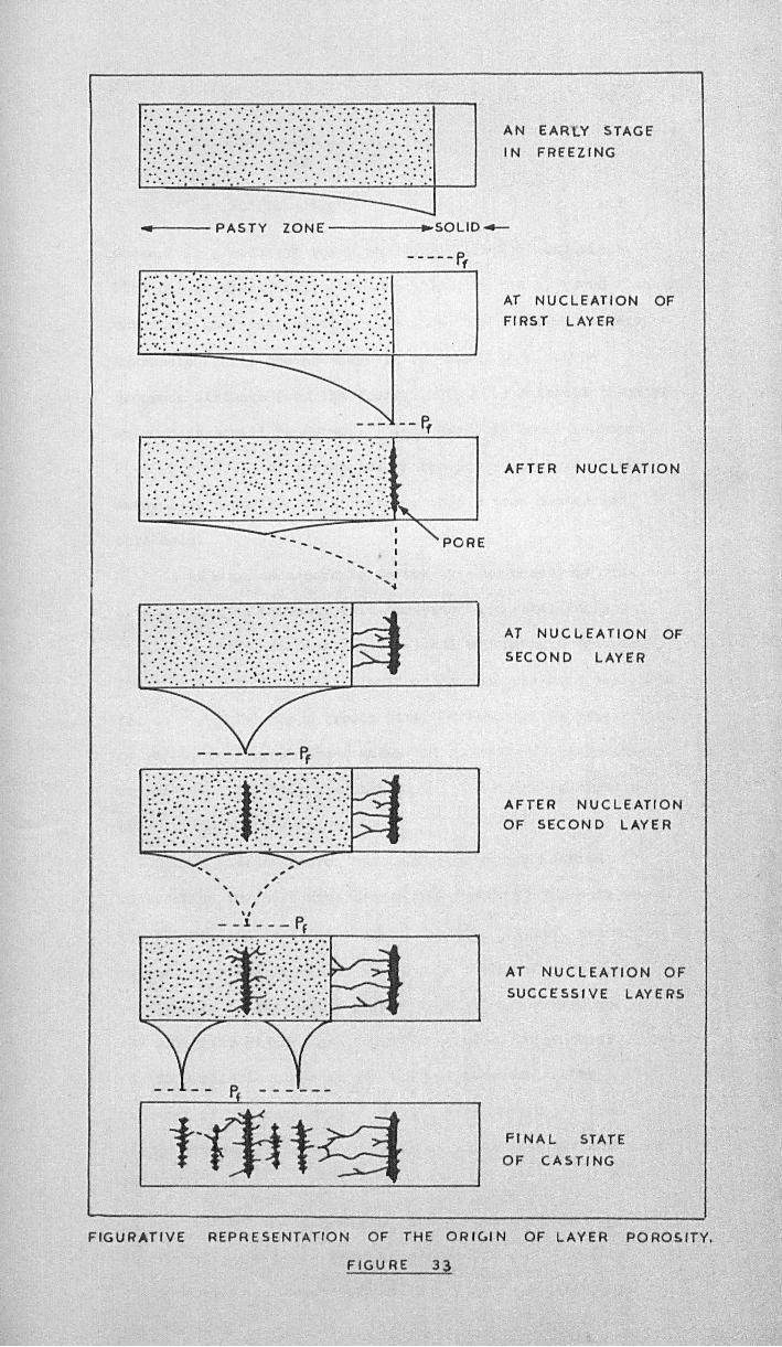
------AN EAR'(Y STAGE
I N FREEZING
...... t---- PAS TY ZON E -------t~~SOLID 4-
, , , , \ ,
-~--
~
.,
\ , - _ 1 - - - Pr
Pf ------
--- --Ff
... : ""'PORE
• I I
..... I .....
AT NUCLEATION OF
FIRST LAYER
AFTER NUCLEATION
AT N U C l.. E A TI 0 N OF
SECOND LAYER
AFTER NUCLEATION
OF SECOND LAYER
AT NUCLEATION OF
SUCCESS I VE LAYERS
FINAL STATE
OF CASTING
FIGURATIVE REPRESENTATION OF THE ORI~I N OF LAYER POROSITY,
FIGURE 33
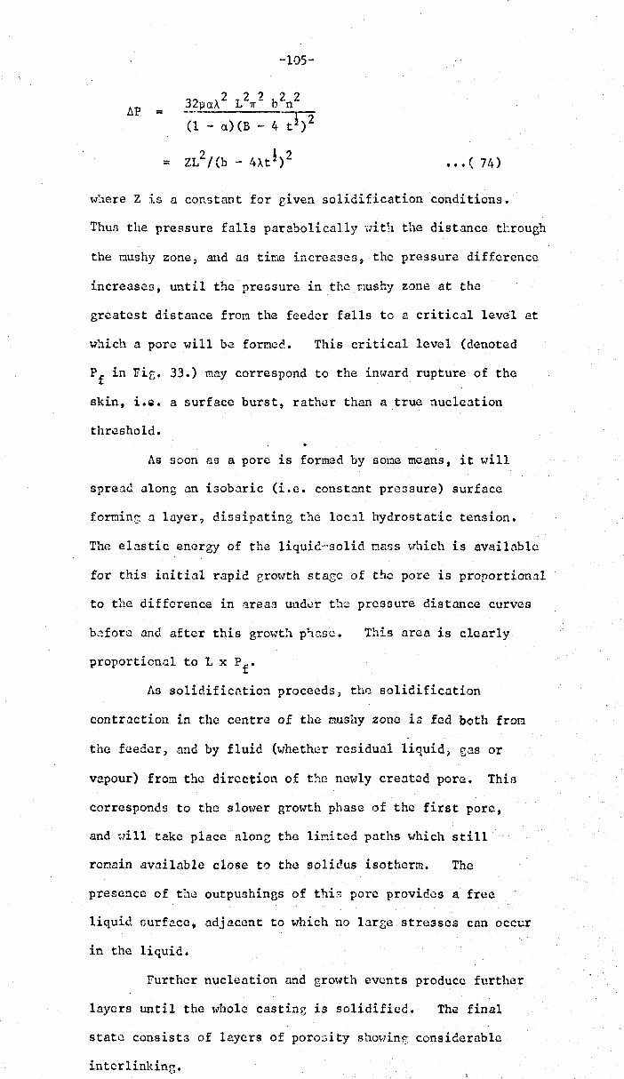
-105-·
b.P = 32paA 2 L2rr 2 b2n2
(~ - a)(B - 4-~)2
= ZL2/(b -·4U!)2 ••• ( 74)
where Z is a co!'.stant for riven solidification conditions.
Thus the pressure falls parabolically \lith the distance tl:rough
the nushy zone, and as tine increases, the pressure difference
increases, until the pre5sure in the r.1Ushy zone at the
greatest distance fron the feeder falls to a critical level at
which a pore will be formec.. This critical level (denoted
Pf in Fiee 33.) may correspond to the inward rupture of the
skin, i.Q. a surface burst, rather than a true nucleation
threshold.
As soon as a porc is formed by sone means, it will
spreau along an isobaric (i.e. constant pressure) surface
fomine; a layer, dissipating the loc')l hydrostatic tension.
The elastic energy of the liquid--solid nass vhich is available
for this initial rapid growth sta[;e of the pore is proportional
to the difference in ~rea3 under the pressure distrulce curves
b,~forc and after this growt!l phcnc. This area is clearly
proporticnal to L x Pf •
As solidification proceeds, the solidification
contraction in the centre of the mushy zone is fed both from
the feeder, and by fluid (whether residual liquid) gas or
vapour) from the direction of tho no\']ly cre.:ltcd pore. Thill
corresponds to the slow'cr growth phase of the first pore,
and Hill take place along the liMited paths w'hich still
remain available close to the Bolicus isotherm. The
presence of the outpushings of this pore providas a free
liquid surface, adjacent to which no large stresses can occur
in the liquid.
Further nucleation and gro\\Ith events produce further
layers until the \\Iho1e castinr.: is solidified. The final
state consists of layers of poro::;ity sho't-ling considerable
interlinking.
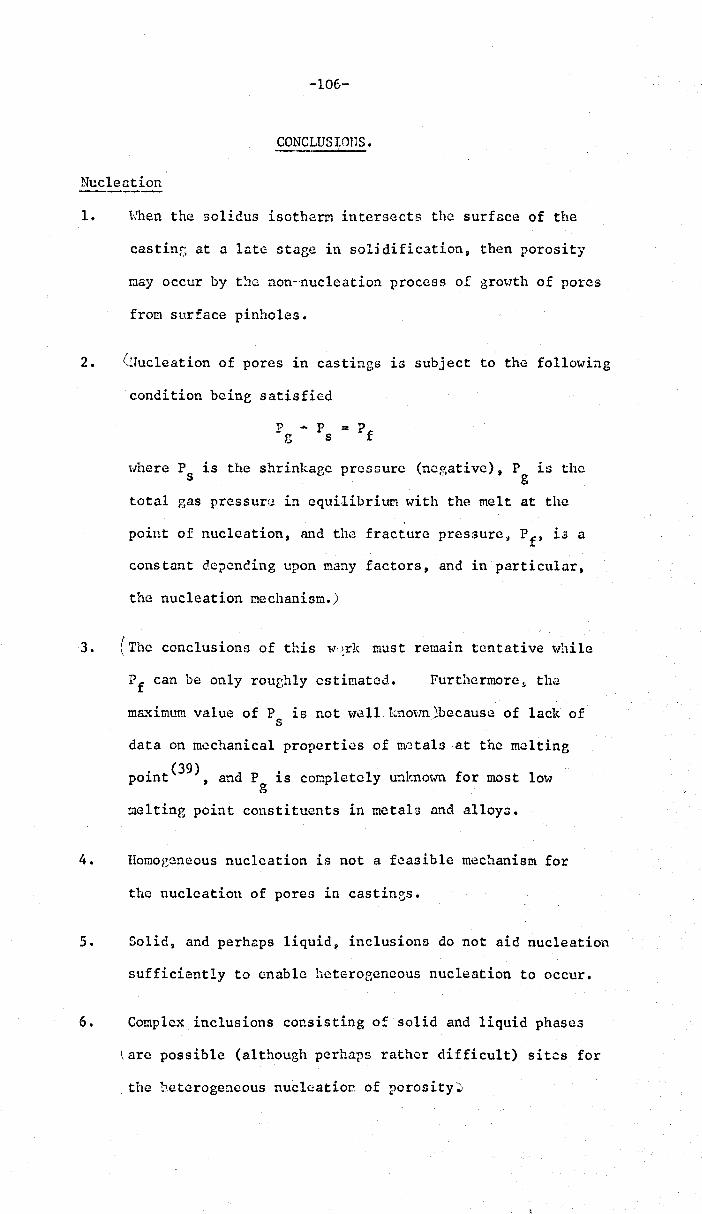
-106-
CONCLUSIons.
Nucleation
1. "{<ilien the solidus isotherm intersects the surface of the
casting at a late stase in soU dification, then porosity
r.tay occur by t!1c non--nucleation process of grOtlth of pores
from surface pinholes.
2. (lluc1eation of pores in castings is subject to the following
condition beine satisfied
\.Jhere Psis the shrinkaec pressure (negative), P g is the
total gas pressure in equilibriUM with the melt at the
point of nucleation, and the fracture pressure, Pft is a
constant clc?ending upon many factors, and in particular,
the nucleation mechanism.)
3. (The conclusions of this l-l.~rlc must remain tentative while
Pf can be only roughly estimated. Furthermore) the
ma..-dmL'ffi value of P is not \'1011 kno't'ffi;,because of lack of s
data on mechanical properties of metals at the melting
point(39), and P is conpletely unknown for most low g
!.1elting point constituents in metals and alloys.
4. IIomo~jcneous nucleation is not a feasible mechanism for
the nucleation. of pores in castings.
5. Solid, and perhaps liquid~ inclusions do not aid nucleation
sufficiently to enable hcterof,encous nucleation to occur.
6. Complex inclusions consisting of solid and liquid phase3
~arc possible (although perhaps rather difficult) sites for
the heterogeneous nucleation of porosity~
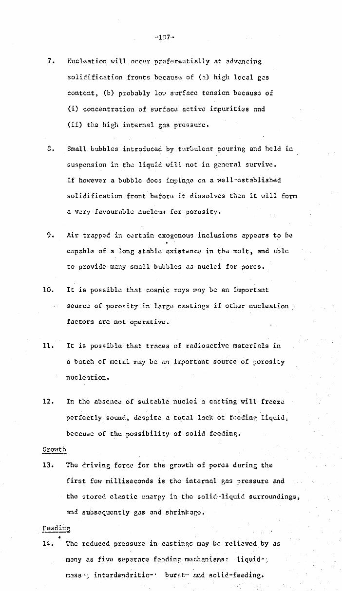
o~107-
7. Nucleation will occur preferentially at advancing
solidification fronts because of (a) high local gas
content) (b) probably lou surface tension because of
(i) concentration of surface active i~purities and
(ii) the high internal gas pressure.
~. Small bubbles introduced by turl:.ulent pouring and held in
suspension in the liquid will not in general survive.
If hm..rever a bubble docs it:lpin~e on a ,oTcll-established
solidification front before it dissolves then it will form.
a very favourable nuc1eu3 for porosity.
9. Air trapped in certain exogenous inclusions appears to be
capable of a long stable existencC! in th,:! melt, and able
to provide many small bubbles as nuclei for pores.
10. It is possible that cosmic rays May be an important
source of porosity in large castinBs if other nucleation
factors arc not operative.
11. It is possible that traces of radioactive materials in
a batch of metal may be an important source of porosity
nuclC:ltion.
12. I~ the absenc~ of suitable nuclei ~ casting will freeze
r>erfectly sound, despite a total lack of fecdinc liquid~
because of the possibility of solid feedine.
Grot-Tth
13. The driving force for the growth of pores during the
first fc\v milliseconds is the internal gas pressure and
the stored clastic energy in the solido-liquid surroundings t
and subsequently eas and shrink ace •
• 14. The reduced pressure in castin~G may be relieved by as
many as five separate fecdin?, mechanisms = liquid-;
mass-; interdendritic- '. hursto .. and solid-feeding.

~l08-
15. Solid feeding is investigated by quantitative theory
using clastic"plc1stic~ BinglUtr.1~ viocous and creep flOt?
models.
16. Experimental ~vidcnce is presented supporting this
effect of necha~ical constraint on porosity.
~~!c<:,;'~f_th~<!9 __ of Solidification on ~orosity.
17. Non"-cquilibriu.ra freezing results in a peak in the
freezing range versus composition relntion for a1leys
of a cutoctic system, corrcspondinp, to a maximum in th~
poros i tY-'compos i tion re lation.
for Fe-C and Al-Cu alloys.
This was demonstrated
18. A theory of the origin of layer porosity is proposed
based on the f10u of liquid throueh the. pnsty zone.
19. A quantitative relation illustrating the cooperative
effects of mould temperature and superheat is proposed.
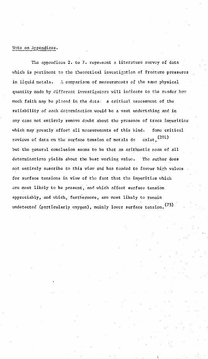
The appendices 2. to 7. repr~scnt a literature survey of data
which is pertinent to the t:teoretical invcstication of fracture pressures
in liquid octals. !~ comparison of rnensureflcnts of the same physical
quantity made by different in.vestieators will indice,te to the reader ho~.r
much faith mn.y be pl.2ccd in the (bta: a critical rlS:3essmcnt of the
reliability of each determination would be a vast undertaking and in
any case not entirely remove doubt about the presence of trace im~urities
~.,hich may greatly affect all mcnsurements of this kind. Some critical
reviews of data on the surface tension of metals do exist, (201)
but the seneral conclusion seems to DC that an arith.u.etic 1."!!cnn of all
determinatio:w yields about the best t<70rking value. The author does
not entirely su.scribe to this viel' and has tCl'lded to favour hir.h values
for surface tensions in view of the fact that the impurities "hich
nrc most likely to be present ~ and \lhich affect surface tenslon
appreciably, und uhich» furtl~ermore, are nost likely to remain
undetected (particularly o~ygen), mainly lo,,;rcr surface tension. (75)

-110-
APPENDIX 1
Cavitation at a Liguid-Liquid Interface
Considering the equilibrium of forces on a bubble at the interface (Fig. 9d)
t 12 Cos e 12 = tl Cos e 1 + t2 Cos e 2
, t 12 Sin (1 12" tl Sin e 1 + ~2 Sin e 2
Further conditions are (C.f. Fig. 9a.)
dllrl .. ~ .. Cos e 1
d2/r2 - m2 .. Cos e 2
••• (1)
••• (2)
and the necessity for the pressure to be everywhere equal inside and
immediately outside the bubble
Pi - P e = 2 t 11 r 1 .. 2 t 21 r 2
thus
••• (5)
Since the curved area of a spherical cap is 2 Tf r2(1 - m), and its
plane area is TTr2 (1 - m2), and its volume ..!!. r3 (2 - 3m + m3), 3
then the work required for the creation of this bubble is
W .. (Area) ¥ + (Volume) (p e - Pi)
+
Differentiating with respect to r 2 and equating to zero gives the 'II-
critical radius, r , of the vapour with the second liquid surfaoe,
'II-
r =
3
2 '(2 [ 2 (1-"2) + 2(1-"1) (i;l - (l-m/) -f; ] (p.- Pi) [(2-} m2 + m/) + ~ (2 -} m
1 + "1
2)J which corresponds to the peak of the energy-radius relation:
.. I 6 T1 ~ 23
3 (p _ p.)2 e J.
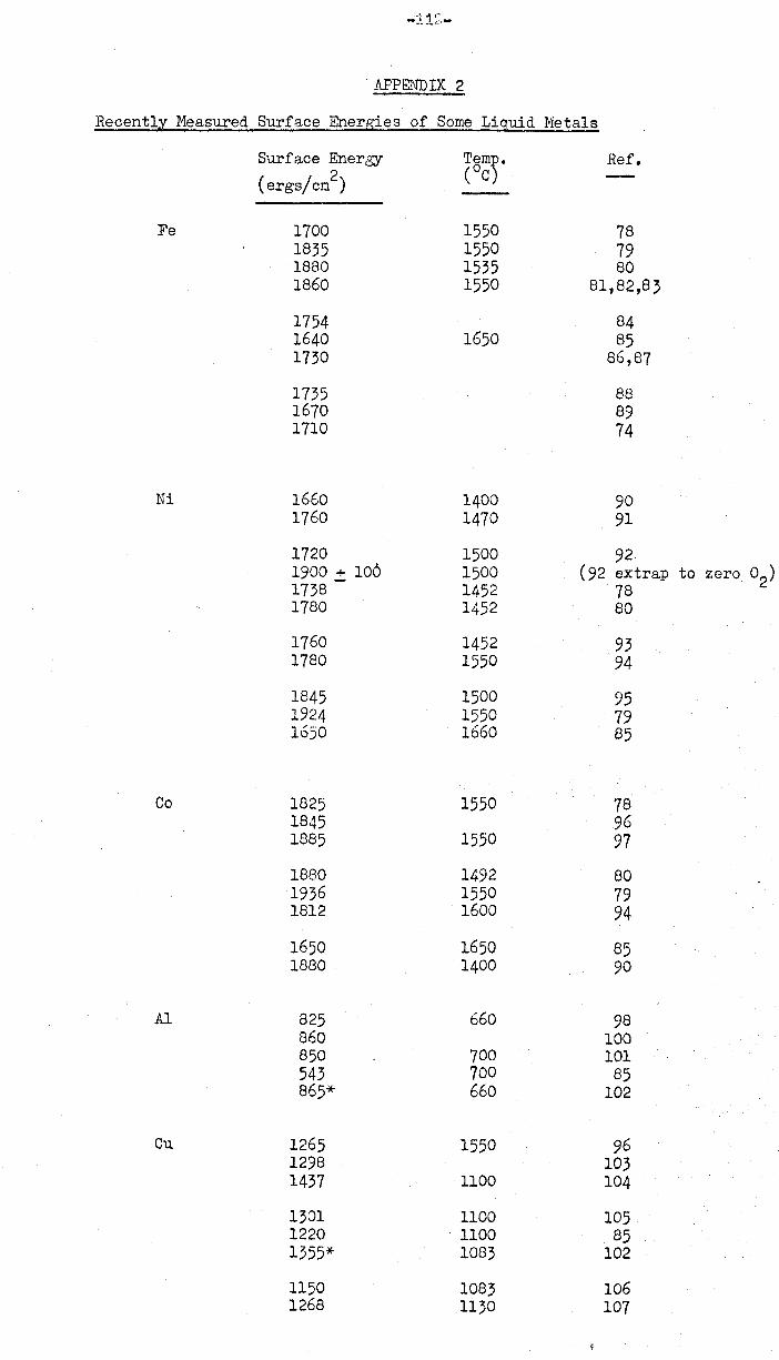
APPENDIX 2
Recently Measured Surface Energies of Some Liquid Metals
Surface Energy
(ergs/cm2)
Fe 1700 1835 1880 1860
1754 1640 1730
1735 1670 1710
Ni 1660 1760
1720 1900 .:!: 100 1738 1780
1760 1780
1845 1924 1650
Co 1825 1845 1885
1880 1936 1812
1650 1880
AI 825 860 850 543 865*
Cu 1265 1298 1437
1301 1220 1355*
1150 1268
T5mp. ( C)
1550 1550 1535 1550
1650
1400 1470
1500 1500 1452 1452
1452 1550
1500 1550 1660
1550
1550
1492 1550 1600
1650 1400
660
700 700 660
1550
1100
1100 . 1100
1083
1083 1130
Ref.
78 79 80
81,82,83
84 85
86,87
88 89 74
90 91
92 (92 extrap to zero O2)
78 80
93 94
95 79 85
78 96 97
80 79 94
85 90
98 100 101 85
102
96 103 104
105 85
102
106 107
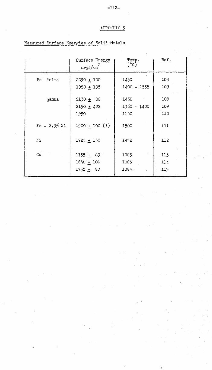
APPENDIX .3
Neasured Surfaee Energies of Solid 1'1etals
Surface Energy Temp. Ref.
ergs/em 2 (oC)
Fe delta 2090 .:t 100 1450 108
1950 .:t 195 1400 - 1535 109
gamma 2130 .:t 80 1450 108
2150 .:t 422 1360 - l400 109
1950 1100 110
Fe - 2.9f" Si 1900.:t 100 (7) 1500 III
Ni 1725.:t 150 1452 112
Cu 1755 .:t 89 • 1083 113
1650 .±. 100 1083 114
1750 .:t 90 1083 115
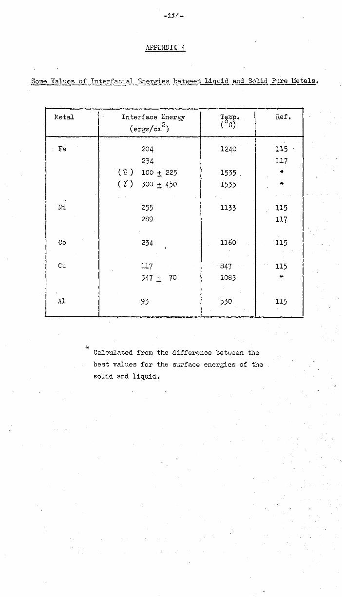
:tvietal
- Fe
Ni
Co
Cu
Al
*
APPENDIX 4
Interface Energy Temp.
(ergs/cm2
) (°0)
204 1240
234 ( ~ ) 100 ± 225 1535 . ( t ) 300 ± 450 1535
255 1133
289
234 1160 . 117 847
347 ± 70 1083
93 530
Calculated from the difference beh!een the
best values for the surface enerGies of the
solid and liquid.
Ref.
115
117
* *
115
117 I 115
, I I
115
*
115

APPENDIU
Some tleasured surface energies of non-metallic liquids
I - Ref. I Surface Energy Temp. I Liquid (composition wt. %)
LV( ergs/ tom 2
) (oC)
! I
Si (Pure) 712 1440' I 118 I 750' 1550' 87 Si (Saturated with Al) 720' ! 119 I
S1O'2 30'7 1800' 120' I SiO'2' 50' l'1gO 40'0' 1750' I 121 I I
1 .' - i
, 390 I 122
8iO'2' 60' CaO' 510' I 160'0' 123 450' 122 400' I 124
SiO'2' 30' CaO' 340' 122 , 389 124 455 160'0' 123 389 160'0' 125
r - - --
SiO'2' 10' Ca~,~_AI2O'3 20'5 1345 127
CI'O' 30' CaO', 15 Al2O'3
. 510' 140'0' 121 f >.l~ 2' 486 1450' 126
8iO'2' 48 CaO', 45 A12O'3 748 1450' 126
8iO'2' 33 CaO', 19 FeO' 444 130'0' 20'3
SiO'2' 42 CaO', 15 P2O'5 396 124
SiO'2' 37 CaO', 8 CaS 380
r 160'0' 123
8iO'2' 24 CaO', 9 CaS, 15 }'igO' 280' 160'0' 123 8iO'2' CaO', Cr2O'5 (minimum i ) 345 160'0' 125
8iO'2' CaO', V 2O'~ (minimum t) 270' l 160'0' 125 SiO'2' 5 CaO', 3 IVlgO' 460' I 150'0' 121
8iO'2' 41 CaO', 34 A12O'3' 10' IIgO 473 . 160'0' 128 I
I SiO'2' 47 CaO', 14 A12O'3' 4 NgO' I 591 ! 1450' 196 SiO'2' 9 CaO', 27 IV]nO, 10' Ce S 290' J 129
8iO'2' 68 FeO' 409 I 1410' 130' 430' 122
8i02, 65 FeO, 5 Fe203 403 1370 131
8iO'2' 24 FeO', 31 MnO' 40'0' 140'0' 131 SiO'2' 30 A1 2O'3' 25 EnO' 280' 1510' 132
FeO' 590' 1420' 131
I 585 1410' 130' 619 1420' 136
I --5"'0'0"--,-1370 --FeO', S FC~.')3 131 I FeO', 16 Fe2O'3' 7.4 CaO' 470' I 1375 131 i
FeO', 7 A12O'3 60'4
I 1410' 130'
FeO', 22 CaO' 573 1410' 130' FeO', 3 Cr 0' 588 1410' 130' FeO', 10 J.VIn6 3 555 L 14::0' 130'
FeO', 18 TiO'2 510' I 1410' 130'

I
I I I I I j
I
I
Some measured surface energies of non-metallic liguids (Cont'd.)
Liquid (composition wt. %) I Surface mergy I 'AI LV(ergs/cm
2) ,
FeS I 585 I 380 I (390)
I 479 '1 U' S 510,570
I .u
3, 2
Cu2S 467 410
P20
5 , 1- 60 i
MnO I 653 I 613
i j CoO
I 555 j
621 ! Nb20
5 I 220 I A120
3 I 700 i I 690 I I 917 .
A1203
, 50 CaO 700 Na20 .28i02 (Sodium silicate glass) 292 CaF 2 274
, AgCl , (109) I BaC12 171 I
I CaC12 152 CsCl I 87
CuCl i 92 I KCl
I 95.8
LiC1 131 I NaCl I 114
PbC12 I 127 RbC1 I 95.7 , SnC12 I (78.8)
Literature survey of surface tensi.ns of liquid
glasses: (140) and (143).
Temp. (oC)
1500 1193 1300 '1193
1300 1130 1130
100 1750 1750
1800 1800
1500 2050 2050 2050
1550 1300
1550
600 960 782 700
450 eoo 780 800
600 750 500
Ref.
133 134 135 136
135 136
I 137
136 138 136
i 138 136
139 138 120 136
i 121 140
141 , .. -
142 142
I 142 142
137 142 1,1·2 142
142 142 142
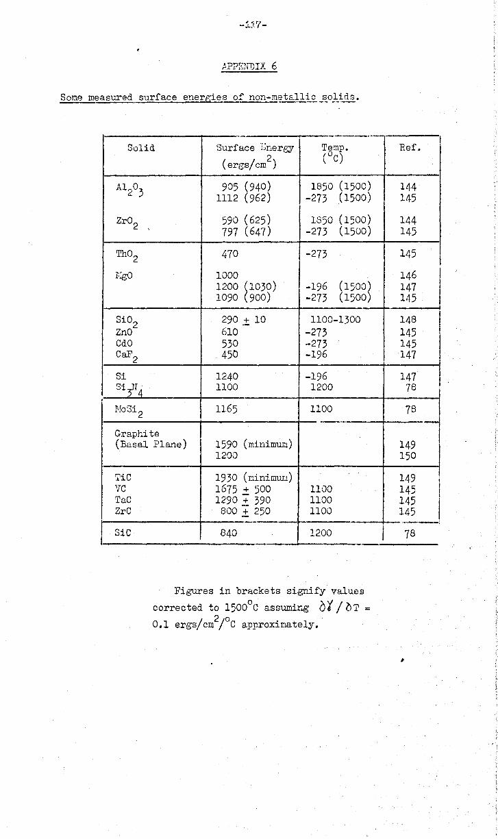
,
I
-1~?-
APPEN"DIX 6
.- ---Solid Surface :'~nergy Temp.
2 (oC) (ergs/em)
A1203 905 (940) 1850 (1500)
1112 (962) -273 (1500)
Zr02 590 (625) 1850 (1500) ,
797 (647) -273 (1500)
Th02 470 -273
EgO 1000 1200 ~1030) -196 (1500~ 1090 900) -273 (1500
Si02 290.± 10 1100-1300 ZnO 610 -273 CdO 530 -273 CaF2 450 -196
Si 1240 -196 Si3N4 1100 1200
NoSi 2 1165 1100 --_ .•. -
Graphite (Basal Plane) 1590 (minimum)
1200
TiC 1930 (minimUlu) vc 1675 .:t 500 1100 TaC 1290 .:t 390 1100 ZrC 800 ± 250 1100
.--- --SiC 840 1200
--
Figures in brackets signify values
corrected to 15000
C assuming 0 t / 0 T = 0.1 ergs/cm2/oC approximately.
I
I
Ref. ,
144 145
144 145
145
146 147 145 , 148 145 145 147
147 78
78 ,-149 150
149 , 145 ! 145 I 145
.... ~.-.-:
78
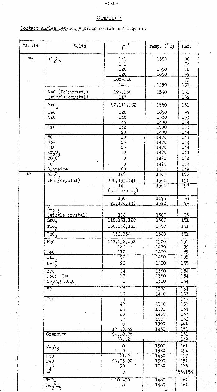
-:1.1[;-
APpmmrx 7
Contact Angles between various solids and liquids.
Liquid Solid 0 Temp. (oC) Ref. e Fe A120
3 141 1550 88 141 .74 128 1550 78 120 1650 99_
100-148 73 141 1550 151
MgO (POIYCryst •. ~ 123,130 lSjO 151 i sin"'le crystal 117 152 Zr02, 92,111,102 1550 151 BeO 120 1650 99 ZrC 140 1500 153
45 1420 154 TiC 132 1500 153
28 1490 154 VC 20 1490 154 NbC 25 1490 154 TaC 23 1490 154 Cr2C
3 0 1490 154
I 110
2C 0 1490 154 , • viC 0 1490 154
Graphite 60 1540 149 Ni A120
3 120 1400 156
(Polycrystal) 128 133.141 1500 151 148 1500 92
(at zero O2)
138 1475 78 121J140~lJ6 1520 99
A1203
(single c~rstal) 108 1500 95 Zr02 118,131,120 I 1500 151 Ti02 105,146,121 1500 151
Th02 132,134 1500 151 ..
JIlgO 132,152,132 1500 151 127 1470 99
neO 110 1470 99
I TaB2
50 1480 155 CrB2 20 1480 155
ZrC 24 1380
1
154 NbC; TaC 17 1380 154 Cr2C
3; H02C 0 1380 i 154
VC 17 1380 . 154 12 1400 I 121 .
TiC 4 149 48 1300 158 23 1380 154 20 1400 157 "?7 lS0n 156 0 1500 161 ..
11 30.32 1450 151 Graphite 90,68,86 151
59.62 149 Cr2C
3 0 1500 161 0 1380 154
UbC 21. 2 1450 157 BeC 90,75,92 1500 151 D
4C 90 1780 176
i,JC 0 56',154
~iB2 100-38 1480 161 10.°2 135
8 1480 161 ~~'- .....
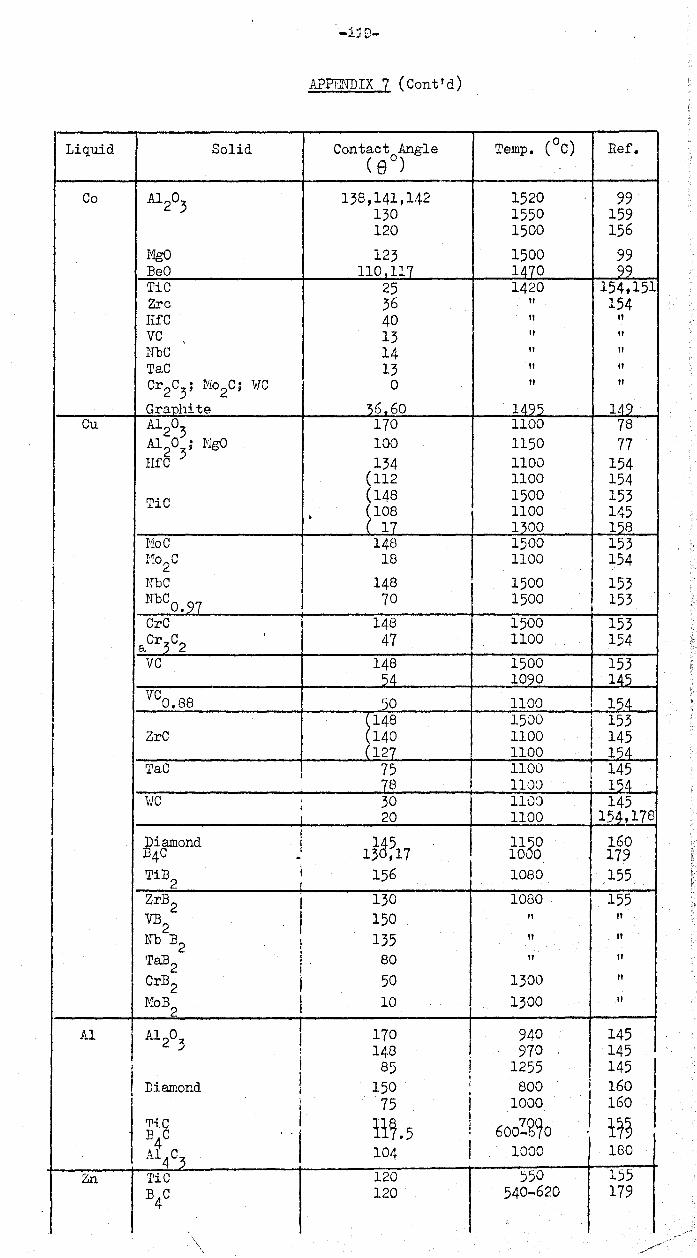
'-1:10-
APPENDIX 7 (Cont'd)
Liquid Solid Contact Angle ( eO)
Temp. (oC) Ref.
Co Al203
138,141,142 1520 99 130 1550 159 120 1500 156
MgO 123 1500 99 ]eO 110,117 1470 99 TiC 25 1420 154,151 Zrc 36 " 154 EfC 40 II " VC 13 It " , NbC 14 " " TaC 13 " " Cr2C
3; N02C; WC 0 " "
Graphite 36,60 1495 149 Cu A120
3 170 1100 78 Al20 ; NgO 100 1150 77 lIfC 3 134 1100 154
(112 1100 154
TiC (148 1500 153 • ~108 1100 145
17 1300 128 HoC 148 1500 153 1'10 C 18 1100
I 154 ~. 2 NbC 148 1500 I 153 NbCO•97 I 70 1500 153
CrC 148 I 1500 153 &.Cr3C2
, 47 1100 154
VC 148 1500 153 54 1090 145
VCO•B8 50 1100 , 154 \148 1500
! 153
ZrC (140 1100 145 (127 1100 I 154
'l'aC I 75 1100 , 145
78 ,
154 I 1100 I
. i
. , i
'vIC , 30 1100 145 t , 20 1100 154,178 ,
Diamond i 15&~17 1160 160 134°
I 10 0 179 . TiB2 I , 156 1080 155
ZrB2 I 130 1080 155
VB2 I 150 " " Nb ]2 135 " " , Ta132
1 80 " " i . Cr132 I 50 1300 " MoB
2 I 10 1300 " I
Al Al 203 I 170 940 145
! 148 I 970 145
I j 85 I 1255 I 145 I i ;
Diamond 150 , 800 i 160 , i i I I ; 75 1000 I 160 i I
'Pi.C I 11~.5 I
600~~90 17~ B4
C "I 1
A14
C3
104 I 1000 180
Zn TiC 120 550 155 B
40 120 540-620 179
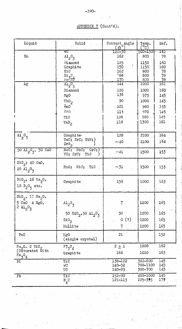
-:t~o-
APPENDIX 7 (Cont'd).
Liquid Solid Contact Angle Temp. Ref. (ti 0) ( °C)
w'V 12U-30 )UU-150~ 14) Sn A1
20
3 162 800 78
Diamond 125 1150 160 Graphite 150
, 1150 160
8iC 162 800 78 8i IT '.68 800 78 IVl038~ 170 800 78
Ag Al203
144 1000 161
Diamond 120 1000 160 MgO 136 975 145 Th02 90 1000 145 Zrlo 101 980 J 15 r.r'1 () 11~ Q70 145
I TiC 108 980 145 TaB2 118 1300 161
----A120
3 Graphi teo 128 2100 164 TaC; ZrC; TiN; ~
,-v 40 2100 164 ZrB2 I 50 Al20
3, 50 CaO NoC; NbC; CrC;)
VC; ZrC; TiC ) ~41 1500 153 I 8i02; 40 CaO,
NoC; NbC; TiC '" 31 1500 153 20 A1203 I
8i02, 16 Na2O, Graphite 158 1000 163
10 B203
etc.
8i02
, 17 Na2O,
5 CaO 4 NgO, Al203
7 1200 165 2 Al20
3 ""
50 8i02,50 A1203
30 1200 165
Si02 o (7) 1200 165
Iv1ullite 7 1200 165
FeO NgO 21 152 (single crystal)
Ns20. 2 Si02 F330
4 2 .± 1 1000 162
(Saturated with Graphite 166 1020 163 Fe30
4 Bi TiC 138-122· 300-600 145
WC 140-52 700-1100 145 UC 140-93 300-700 145
Pb TiC 152-90 400-1000 145 B
4C 121-113 225-3'5' 173
.....

IMAGING SERVICES NORTH Boston Spa, Wetherby
West Yorkshire, LS23 7BQ
www.bl,uk
Best copy available
Print close to the edge of
the page and some cut off
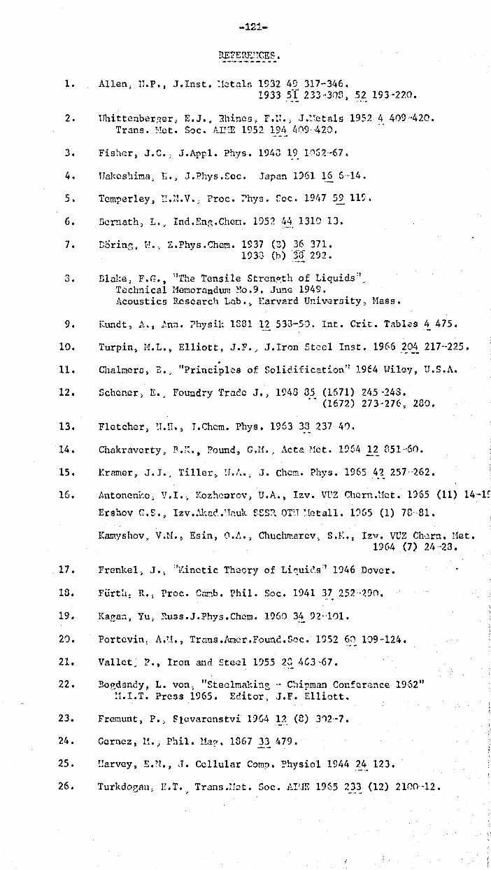
-121-
nEFERE!lCES.
1. Allen, 11.P., .I.lnst. :!ctal13 1932 49 317-3,~6.
1933 .5I 233-303 ~ 52 193-220.
2. Hhittenber:<er" E.J •• 1hines, F.U.; .J.~~eta1s 1952 4 409·420. Trans. Het. Soc. Arm 1952 19/. l,09- ,420.
3. Fishcr~ J.C.,; .I.Appl. Phys. 1943191052,-67.
4. HaJ<cs~liI!1.a. l~.> J.Phys.Soc. Japan 1961 1~ 6·14.
5. Tcmper1ey, r~.n.v.; Froc. :'hys. f.oc. 19/.7 59 11~.
6. Bernath, L ... Ind.En~.Ghcn. 1952 4_~. 1310 13.
7. Doring, E., Z.Phys.Chcm. 1937 (3) 36 371. 193:) (b) -~~ 292.
3. Blake) F.G., \fThc Tensile Strcn?;th of Liquids:', Technical HeI!1.0rllndum !,-10.9. June 1949. Acoustics Research Lab.~ l:arvard University, Hass.
9. KU1"H~t, A., "':nUt 'Physik 1381 12 533-50. Int. Crit. Tables 4 475.
10. Turpin~ 11.L., Elliott, JoF.) J.lron Steel Inst. 1966204 217'·225 • . 11. ChalmerD~ B., "Principles of SolicHficationl: 19E4 Uiley, U.S.A.
12. Schaner, E., Foundry Trade J'J 1948 35 (1671) 21f5-24S • .. (1672) 273-276. 230.
13 • Fletcher, ~J. 11. ~J • Chern. Phys. 1963 3 . .:3. 23741).
14. Chakravcrty) P.;~., Pound~ G.H., Acta ~1et. 1%4 12 851--60.
15. Kramer, J.l., Til1cr~ H.l..~ J. Chern. Phys. 1965 42 257·<~62.
16. Antoneuy.o, V.!., Koz!'l.c\'llrov J U .A., Izv. VUZ Chern .Hot. 1955 (11) 14-1~
Ershov G.!:.» Izv •• \l;.cc" .• ;1nuk f£S,?\. OT'! ~.!ctall. l,)GS (1) 7r.-·8t.
Kamyshov, V.H., Esin, f).! •• , Chuchrr.arcv~ S.K q Izv. VUZ ChDrn. Het. 1964 (7) 21~·23.
17. Frenkel, J.~ aKinetic Theory of Liqui~.sa 1946 Dover.
10. Fiirth~ R., Proc. CamhI Phil. Soc. 1941 37 252'-'290.
19. Kaga~1. Yu, Russ.J.Phys.Chem. 1960 34 91--101.
20. Portevin\ A.U.~ Trnns.Arncr.Found.Soc. 1~52 60 1·J9~124.
21. Vallet, P., Iron and Ste.-;l 1955 2_~ I.G3 ·67.
22 Bo t'>dan~ L von "COt 1 ',' C' • C f 19(..2" • (; UY). I'" ee mat,l!1e - .upman on crance ~,
11.I.T. Press 1965. Editor. J.F. Elliott.
23. Fremunt, P., ~lcvarenstvi 19G4 1}_ (8) 312-·7.
24. Gernez, H. J rhil. Ua? 1067 l~ 479.
25. I!arvey, E.N., .T. Cellular Com~. ?hysio1 1944 24 123.
26. Turkdoeau, E.T. Trans.!1~t. Soc. Arm 1965 2_~~ (12) 2100,-12.
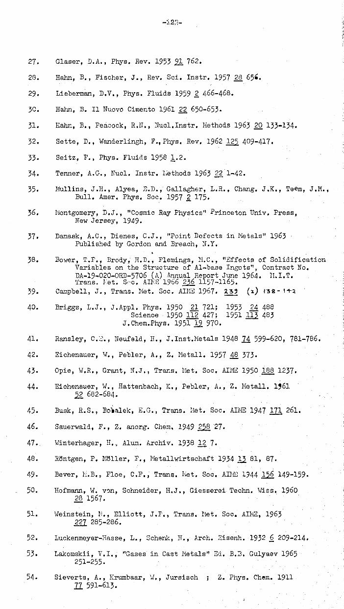
27. Glaser, D.A., Phys. Rev. 19532! 762.
28. Hahn, B., Fischer, J., Rev. Sci. Instr. 1951 ~ 65'.
29. Lieberman, D.V., Phys. Fluids 1959 £ 466-468.
3C. Harm, B. II Nuovo Cimento 1961 22 650-653.
31. Hahn, B., Peacock, R.N., NucI.lnstr. Nethods 1963 20 133-134.
32. Sette, D., Wander1ingh, F.,Phys. Rev. 1962 125 409-411.
33. Seitz., F., Phys. Fluids 19581.2.
34. Tenner, A.G., Nuc1. Instr. Nethods 1963 22 1-42.
35. Mullins, J.H., Alyea, E.D., Gallagher, L.R., Chang. J.K., Teem, J.M., Bull. Amer. Phys. Soc. 1951 £ 115.
36. Nontgomery, D.J., "Cosmic Ray Physics" Princeton Univ. Press, New Jersey, 1949.
31. Damask, A. C., Dienes, G.J., "Point Defects in Netals" 1963 Published by Gordon and Breach, N.Y.
38. Bower, T.F., Brody, H.D., Flemings, N.C., "Effects of Solidification Variables on the Structure of AI-base Ingots"~ Contract No. DA-19-020-0RD-5106 (A) Annual Report June 1964. lI.l.T. rrrans. Eet. Snc. AIN2; 1966 ~ 1157-1165.
39. Campbell, J., Trans. Net. Soc. AIHE 1961. 2.3' (2.) r3S- I+l
40. Briggs, L.J., J.Appl. Phys. 1950 21 121; Science 1950 11£ 421;
J.Chem.Phys. 195112910.
1953 £1 488 1951 ill 483
41. Ransley, C.::]., Neufeld, II., J • Inst.Neta1s 1948 1.4 599-620, 781-786.
42. Eichenauer, 1",., Pebler, A., Z. Netal1. 1957 .1§. 373.
43. Opie, W.R., Grant, N.J., Trans. Het. Soc. AINE 1950 l.§Q 1237.
44. Eichenauer, W., Hattenbach, K., Peb1er, A., Z. NetalI. 1,61 .2 682-684.
45. Busk, R.S., BOla1ek, E.G., Trans. Het. Soc. AHlE 1947 171 261.
46. Sauerwa1d, F., Z. anorg. Chem. 1949 ~ 27.
47. vrinterhager, H.~ Alum. Archiv. 1938 12 7.
48. RBntgen, P. HBller, F., IvIeta11wirtschaft 193412.81, 87.
49. Bever, l'~.B., Floe, C.F., Trans. Het. Soc. AUlE 1344 156 149-159.
50. Hofmann, \{. v':m, Schneider, H.J., Giesserei Techn. vliss. 1960 28 1561.
51. Vleinstein, I;!., Elliott, J .F., Trans. Bet. Soc. AHIE, 1963 m 285-286.
52. Luckenmeyer-Hasse, L., Schenk, H., Arch. Eisenh. 1932.£ 209-214.
53. Lakomskii, V.I., "Gases in Cast Netals" Zd. B.3. Gulyaev 1965 251-255.
54. Sieverts, A., Krumbaar, \1., Jursisch ; Z. Phys. Chem. 1911 II 591-613.

55.
56.
51.
58.
59.
60.
61.
62.
63.
64.
65.
66.
61.
68.
10.
11.
12.
73.
14.
15.
76.
11.
18.
79.
80.
Liang, H., Bever, H.B., Floe, C.F., Trans. Het. Soc. AIME, 1946 167 395-403.
Bagshaw, T., Eng1edow, D., 1~tohe11, A., J.Iron Steel Inst., 1965 203 160-165.
Busch, T., Dodd, R.A., Trans. Met. Soc. AUIE 1960 218 488-490.
Briggs, H.B., Johnson, J.13., Hasan, 1~.P., J. Acoust. Soc. Amer. 1947 12 :';64.
Thorndike, A.~~., Scientific Res. & Dev. Section C-4. Rep. No. 81496.
"Gme1ins Handbuch der ~.norganischen Chemie. Koba1t, Tei1 A. Erganzungsband" Verlag Chemie, "Teinheim, 1961.
Bagshaw, T., Hitchel1, A., J. Iron Steel Inst., 1966 204 87-90.
Sieverts, A., Zapf. G., Hori tz, H., Z.Phys.Chem. 1938 ill 19
Burdese, A., Neta11urgia Ital. 1955 .41. 357 366.
Peh1ke, R.D., Elliott, J.F., Trans. Met. Soc. AI}~ 1960 218 1088-1101.
Dodd, R.A., Gok ~n, N .A., Trans. Met. Soc. ADm: 1961 221 233-236.
Tankis, S., Gokcen, N.A" Trans. A.S.U., 1961.2.i 843-852.
Dastur, li.N., Chipman, J., Trans. Het. Soc. AUiE 1949 185 441-445.
Averin, V. V., Po1yakov, A. Yu., Samarin, A.h. Izv. Akad. Nauk SSSR OTN 1957 (8) 120-122.
Tankins, .c.S., Gokoen, N.h.., Belton, G.lt., Trans. Net. Soc. AHfE 1964 230 820-827.
Epstein, H., Chipman, J., Grant, N.J., Trans. Net. Soc. AIhE 1957 209 597-608.
Parlee, N .A., Foundry 1956 Q.4. Aug. 80-87.
Banya, S., 1-1atoha, S., 1959 "Physical Chemistry of Process Metallurgy" Pt. 1. Vol. 7. Interscience, H". Y.
Chipman, J. "Basic Open Hearth Steelmaking" 2nd Edition, N.Y. 1951.
Halden, F.A., Kingery, v/.D., J. Phys. Chem. 1955.22 557.
Tsarevskii, B.V., Popel, S.I.,Fiz. Khim. Osnovy Proizv. Stali., 1961, 97-105.
Wang Ching-T 'ang, Karasev, R.A., Samarin, A.N. Fiz. Khim. Osnovy. Proizv. Sta1i, Noscow 1961, 106-111.
Kurochkin, K.T.~ Bauro, B.V., Borodulin, E.K., Fiz. Met. Metall. 1963 12 (3) 461-462.
Eremenko, V.N., Naidich, Yu. V., Nosonovich, A.A., Z. Fiz. Khim. 1960 21 (5) 1018-1020, (6) 1186-1189.
Allen, B.C., Kingery, Iv.D., Trans. Het. Soc. AHIE 1959 ill 30-36.
Kozakevitch, P., Urbain, G., J. Iron Steel lnst. 1957 186 167-173.
Allen, B.C., Trans. 1let. Sao. AlNC 1963 m 1175-1183.
81. Kurochkin, K.T., Baum, B.A., Borodulin, E.K., 1963 Fiz. Met. Hetal1. 12 (3) 461-462.
82. Baum, B.A., Kurochkin, K.T., Umrikhin, P. V., Phys. Net. ~1etal1. 1961 11 (6) 139-140. Izv. A.N. Het. i Toplivo 1961 (3) 82-89.
83. Volkov, S.E., Mchedlishvili, V.A., Samarin, A.M., Docklady Akad. Nauk SSSR 1963 112 (5) 1131-1133.
84. Dyson, B.F., Trans. het. Soc. An-IS 1963 m 1098-1102.
85. Honma, K., Suto, H., Trans. Japan Inst. Het. 19601. Oct. 69-76.
86. Popel, S.I., Tsarevsky, B.V., Dzhemilev, N.K., Fiz. },Iet. Metallo 1964 18 (3) 468-470.
87. Dzhemilev, N.K., Popel, C.I., Tsarevskii, B.V., Fiz. Net. Matall. 1964 18 (1) 83-87.
88. Smirnov, L.A., Popel, S.I., Tsarevskii, B.V., Izv. VUZ Che~.Met. 1965 (3) 10-14.
89. Vishkarev, A.F., Kryakovskii, Yu. V., Bliznyukov, S.A., Yavoiskii, V.I., Izv. VUZ Chern. }'~et. 1962 (3) 60-66.
90. Tumanov, V.I., Funke, V.F., Belen'yaya L.I., Usol'teva, L.P., Izv. Akad. Nauk. SSSH Net i Top1ivo 1962 (Tekhn) (6) 43-48.
91. Kingery, W.D., Humenik, ril., J .Phys. Chem. 1953 21 359.
92. Eremenko, V.N., Naidich, Y.V., Izv. Akad. Nauk SSSR Met. i Top1ive 1960 ,g 53-55.
93. Eremenko, V.N., Nizhenko, V.I., Ukrain. Khim. Zhur. 196429. (2) 125-132.
94. Eremenko, V.N., Nizhenko, V.I., Ukrain. Khim. Zhur. 1960 26 423-428.
(Armstrong, IIT.M., Chaklader, A.C.D., Clarke, J .F., J .Amer.Ceram.Soc. 95. ( 1962 .42. 115-118.
(Clarke, J.F., M.S. Thesis, Univ. Br. Columbia, 1959.
96. Fesenko, V.V., Vasiliu, M.L, Eremenko, V.N., Zhur. Fiz. Khim. 1962 2£ (3) 518-520. Russ. J. Phys. Chern. 19622£269-271.
97. Eremenko, V.N., Naidich, Yu. V., Vasi1iu, H.L, Izv. Akad. Nauk SSSR (Otdel Tekhn) Het. i Gornoe De10 1963 2. 64-66.
98. Davies, V. de L., ldest, J .M., J. Inst. Hetala 1963-64, .2,g, (7) 208-210.
99. Eremenko, V.N., Ivashchenko, Yu N., Nizhenko, V.I., Fesenko, V.V., I zv. Akad. N auk SSSR Otd. Tekh. N auk 1958 1 144-146.
100. Korolkov, A.N., "Casting properties of metals and alloys" Consultants Bureau Trans. 1960.
101. Kubichek, L., Izv. Akad. Nauk SSSR Met i Top1. 1959 (Tekhn) (2) 96.
102. Naidich Yu, V., Eremenko, V.N., Phys. Het. NatalI. 1961 11 (6) 62.
103. Kozakevitch, P., Chatel, S., Urbain G., Sage, h., Rev. Net. 1'55 ..2. 139-16 o.
104. Lauerman, I., Sauerwald, F., Z. Meta11k. 1964 12~(10) 605-612.
105. Netzger, G., Z. Phys. Chern. 1959 211 1-
106. Calverley, A., Proc. Phys. Soc. 1957 70B 1040.
107. Belforti, D.A., Lepie M.P., Trans. Met. Soc. AI}m 1963 ggz 80-83.
108. Hondros, E.D., Proc. Roy. Soc. 1965 286A 479-498.
109. Price, A.T., Hol1, H.A., Greenough, A.P., Acta Met. 1964 12 49-58.
110. Mazanec, K., Kamenska, E., Phys. Met. Neta11. 1961 12 .(1) 79-83.
111. Jones, H., Leak, G.M., Acta Het. 1966 II 21-27.
112. Hayward, E.R., Greenough, A.P., J.lnst.Metals 1960 ~ 217.
113. Hoage, J .H., Hanford Atomics 1963 H. '4. 78132.
114. Udin, H., Trans. Net. Soc. AlME 1951 ill 63.
115. Pranatis, A., Pound, M., Trans.Met.Soc. AINE 1955 20,2 664.
116. Turnbull, D., J • Appl.Phys. 1950 n:. 1022-1028,
117. "lard, R.G., J. Australian. Inst. Metals. 19651Q (3) 278.
118. Shashkov Yu, H., Kolesnikova, T.P., Russ. J. Phys. Chern. 1963 2l. (6) 747-748.
119. Gel'd, P.V., Petrushevskii, M.S., Izv. Akad. Nauk SSSR Otd. Tekh. Nauk 1961 (3) 160.
120. Kingery, \/.D., J. Amer. Ceram. Soc. 1959.11 6-10.
121. Popel, S.I., Esin, O.A., Russ. J. Inorg. Chern. 1957 11 (3) 252-269.
122. King, T.B., Symposium Phys. Chem. of He1ts 1953 Inst. }1ining Metallurgy, London.
123. Panov, A.S., Kulikov, I.S., Tsylev, L.N., Russ. J. Phys. Chem. 1962 22. 722-723.
124. Cooper, C.F., Kitchener, J.A., J. Iron Steel Inst. 195912248-55.
125. Swisher, J.H., McCabe, C.L., Trans. Met. Soc. AlNE 1964 230 1669-1675. .
126. Kozakevitch, P., "Liquids; structure, properties, solid interactions" Hughe1, T.J., 1965, Elsevier, Amsterdam.
127. Ermo1aeva, E.V., Ogneupory 1955 20 221-228.
128. Smolyarenko, V.D., Yakushev, A.Ili., Edneral, F.P., Izv. VOZ Chern. Met. 1965 (3) 36-41.
129. lIUkiashvili, S.N., Soobshch. Akad. Nauk Gruz SSR 1962 g,2 (5) 549-554.
130. Kozakevitch, P.P., Kononenko, A.F., Russ. J. Phys. Chern. 1940 llll18.
131. Popel, S.I., Esin, O.A., Zhur. Piz. Khim. 1965 2Q 1193.
132. Nikiashvili, S.}~., Samarin, A.li., Tsylev, L.N., Izv. Akad. Nauk SSSlt Otde1 Tekh. Nauk 1957 ~ 54-62.
133. King, T.B., J. Soc. Glass Tech. 195122241-259.
-12G-
134. Leonteva, A.A., J. Colloids USSR 1949 11 (3) 176-171.
135. Kheifets, B.L., Sheinin, A.B., Zhur. Prikl~ Khim. 1959 2,g 1039-1042.
136.
137.
138.
139.
140.
141.
142.
143.
144.
145.
146.
147.
148.
149.
150.
15I.
152.
153.
154.
155.
156.
157.
158.
159.
Sok010v, O.K., Izv. Akad. Nauk SSSR Otde1 Tekh. Nauk Metal1. 1965 (1) 97-103.
Eoni, R., Derge, G., J. Metals 1956 ~ 53-64.
Lepinskikh, V.M., Esin, O.A., Teterin, T.A., Zhur. Neorgan, Khimii 1960 2 (3) 642.
Manakov, A.I., ESin, O.A., Lepinsk1kh, B.M., Russ. J. Phys. Chern. 1962 22 1257-1259.
Appen, A.A., Schischow, K.A., Kayalov, S.S., Si1ikat Tech. 1953 ..4 104-105.
Evseyev, P.P., Filipov, A.F., Izv. VUZ Chern. Met. 1965 (3) 70-73.
Int. Crit. Tables 1930 Nat. Research Council, U.S.A.
Mitchell, D.W., Mitoff, S.P., Zackay, V.F., Pask, J.A., Glass Ind. 1952 ~1.515-523.
Kingery, W.D., J. Amer. Ceram. Soc. 1954 iI 42-45.
Livey, D.lv., Murray, P., J. Amer. Ceram. Soc. 1956 22. 363. Plansee Proe. Chapter 32 (Ed. F. Benesovsky) 1956.
Jura, G., Garland, C., J. Am. Ceram. SOOt 19521i 6033.
Gilman, J.J., J. Appl. Phys. 1960212208-2218.
Parikh, N., J. Amer. Ceram. SOOt 1958 ~ 18.
Humenik, M., Whalen, T.J., "Cermets" Chapter 1. Editors: Tink1epaugh, J.R. and Crandall, W.B., Reinhold Publishing Co. 1960.
Patterson, itT., Ammann, D., Engler, S., Giesserei Teohn.-~.,riss. Beiheft 1958 10 1031.
Humenik, H.H., Kingery, W .D., J. Amer. Ceram. SOOt 1954 2118-23.'
Armstrong, W.N., Chaklader, A.C.D., Rose, D.J., Trans. Net. SOOt ADJE 1963 m.. 1109-1115.
Kamyshov, V.rl!., Esin, O.A., Chuohmarev, S.K., Zh. Fiz. Khim. 1966 .1Q. 262-263.
Ramqvist, L., Int. J. Powder r1et. 1965 1 (4) 2-21.
Ereremenko, V.N., Naidich, Yu, V., Russ J. Inorg. Chern. 1959 .4 (9) 931.
Tumanov, V.I., Funke, V.F., Bel erucaya , L.I., Russ. J. Phys. Chern. 1962 2.§. 841.
Tumanov, V.I., Funke, V.F., Be1enkaya, C.I., Soviet Powder Met., 1963 2 (11) 316-318.
Whalen, T.!., Humenik, N., Trans. Net. Soc, AlME 1960218-952-956
Eremenko, V.N., Nizhenko, V.I., Russ. J. Phys. Chern. 1961 22. (6) 638-640.

160. Naidich, Yu, V., Ko1esnichenko, G.A., Soviet Powder Net. 1964 (3) 191-195. 1963 1 (13) 35-38.
161. Eremenko, V.N., Naidich, Yu, V., "The Wetting of Refractory Compounds with Liquid Metals", Akad. Sci. Ukrain. SSr., Kiev. 1958.
162. Cline, R.W., Fulrath, R.M., Pask, J.A., J. Amer. Caram. Soc. 1961 ..4i 423-428.
163. Ellefson, B.S., Taylor, N. vI., J. Amer. Ceram. Soc. 1938 21 193,205.
164. Bartlett, R."'., Hall, J .K., Bull. Amer. Ceram, Soc. 1965 .4.4. 444-448.
165. Comeford, J.E., Hursh, R.K., J. Amer. Ceram. Soc. 195222130-134.
166. Popel, S.I., Esin, O.A., Geld, P.V., Dok1. Akad. Nauk SSSR 1950 ~ (6) 1097-1100.
167. Esin, O.A., Nikitin, Y.P., Popel, S.I., Dek1. Akad. Nauk SSSR 1952 .§2. (3) 431.
168. Kozakevitch, P., Urbain"G., Sage, }f., Rev. Nliit.19552,139,161. (Transl. in Iron Coal Trade Rev. 1955 170 963).
169. Mori, K., Fajimura, T., Tetsu-to-Hagane 1955 ~ 495-500.
170. Mikiashvi1i, S.rI., Samarin, A.H., Tsy1er, L.N., Akad. Nauk SSSR Otde1. Tekh. Nauk 1957 .4. 54-62.
171. Popel. S.I., Esin, O.A., K~novalov, G.F., Smirnov, N.S., Dokl. Akad. Nauk SSSR 1957 112 104-106.
172. Yakobashvi1i, S.B., Frumin, 1.1., Avtom. Svarka 1961 1Q (103) 14-19.
173. Yakobashvi1i, S.B., Avtom. Svarka 1962 ~ (113) 38-43.
174. Smo1yarenko, V.D., Yakushev, A.li., Ednera1, F.P., Izv. VUZ Chern. )\let. 1965 (3) 36-41.
157. TIobkova, O.S., Petukhov, V.S., Zhe1adnov, V.I., Sbornik 'rrudov Tsniichm. Tecria l'leta11. Protsessev 1965 .4..Q 35-40.
176. Hamijan, H., Lidman, \!., J. Amer. Ceram. 300. 1952 .l2. 44.
177. Baxter, J., Roberts, A., POlo!der Netal1urgy Symposium, London, Iron & Steel Inst.~ 1954 p. 63.
178. Garland, J., Norton, L., J. Hetals 1952 .4. 1051.
179. Samsonov, G.V., llarkovskii, L. Ya., Zhigach, A.F., Balyashko, N.G., Boron, Its Compounds and Alloys, Izd. A N UkrSSR, Kiev 1960.
180. Belyaev, A.I., ZheI!1ohuzhina, ;i.A., Surface Phenomena in lleta11ic Processes, l-leta11urgizdat, Loscow 1952.
-123-
181. Shafrin, E.G., Zisman, H.! .. ~ Adv::m.Chcm.Ser. 1964 43 145-157.
182. Sulliv:-m~ E.L., lkrdy, B.H.~ Hollai.ld, C.P., .. \ro. lnst. Chern. Eners. J. 1964 10 (6) S48-~54.
133. Joutz, P.D., Hyero, J.E., An.Inst.Chem.Engrs.J.1960 E.. 34-38.
134. Newman, P.C. ~ 17hcl~11, P.F., Ibture (London), 1952 1.69 326.
135. Hsu~ Y.Y., J. Heat Trnnsfer, 1962 .~4 207-216.
186. Outhwaite, J.G., "Gases in Liquid Hcta1sll~ Ph.D. Thf.!sis, Birmincham Univ(;rsity 1961.
137. Lieberoan, L •• .J. App1. Phys. 1957 28 205-211.
1133. Epstein, P.S., P1c3set, H.S., J. Chcm.Phys. 1950 .!.~ 1505~·1509.
109. P1esset, 11.5., Zwick, S.A., J.Appl.Phys. 1954 _25 493-500.
190. Forstcr J H.!:., Zuber, N., J.Appl.Phys. 1954 _?~ 474.
191. Birkhoff, G.~ Margulies, R.S., Ilornine, H.A., Phys. Fluids 1953 1 201"204.
192. Barlow, E.J., Lan~lois, ~,J.E.) I.E.H. J. Res. Develop. 1962 £> 239-237.
193. Z.'lduITIkin, S.N., Russ.J.Phys.Chem. 1961 35 (12) 1397-1~93.
194. Reiss, H., Hilson, LB., J. CoHoic. Sci. 1948 3 551-561.
195. Byers, H.R., Chtl.ry, S.l:., Z.Ange\17 Nath.Phys. 196314428,,-433.
196. ~hcherbakov, 1.1'1.,
Isslcd. v. ObI. Povcrkhn. Sil, lJ<.ad Nuuk SSR Inst. Fiz. Khim., Sb. Dok1. na Vtoroi !couL, Hosco~v 1962 17-25. (Published 196~) Chern. Abs. ?_~ 972, 9451.
197. Shcherb I1ko\T, L.H.~ Rykov, V.I.~ Kolloid Zhur. 19G1 23 221-227.
198. Kirk\lOod} J.G., Euff, F.P.~ J.Chem.Phys. 1949 .!l. 333.
199. Buff, F.P., J.Chem.Phys. 1951 19 1591-1594 1955 23 419·-427.
200. Bellemans ~ A., Physica 1963 2~ (5) 543-554.
201. Flint, 0., J. Nuclear Mnt. 1965 16 233-248.
202. Dean, R.B., J.App1.Phys. 1944 ]5 (5) 446--451.
203. Han:Jon, D., PeU-v1n1po1c, H.T., "Chill-Cast Tin Bronzes ll
1951 Arnold, London.
204. Hudson, F., Trans.Amer.Found.Soc. 1965 73 65--33.
205. Dehaven, J., Davis, J .A., East\vood, L.1i1., Trans .Am. Founc.Soe. 1945 53 180-9.
206. Flinn, R.A., Tr::ms.Amer. Found.Soe. 1956 64 665~7. ,
207. Savie, P., Gosnell, J.r,r., Can.J.Chem.Engr. 1962 40 233-45.
--129-·-
208. To1ubinskii, V.I., Che~.Abs. 1963 59.1 227.
209. Strn1en~ 5.J.D. van, Physics 1963 29 (6) 602-15.
210. Davbs~ V. de L., J.lnst.:1eta1s 1963--64 9? 127;: 1964··65 -~)3 10.
211. Rayleigh (Lord), Phil. Uag. 1917 34 94·-98.
212. Silver, R.S., Engineering 1942 154 501-2.
213. Blake, F.G.~ "The Onset of Cavitation in Liquids: In Tech. Hemo !lo.12. Acoustics Research L:lb.~ Harvard Univ. 1949.
214. Ruddle? R. t-l., "The Solidification of castings!i Inst. Hetals 1-lonograph No.7. 1957. Revised 2nd Edition.
215. 'R.arnqvist, L., POHder Met. 19662.(17) 1-25.
216. Nelson, R.S., Hazey, D.J., Barnes~ R.S •• , Phil. Uag. 1965 ~1:. (109) 91--111.
217. Hoffman, R.D. _ ~jyersJ R. R. , Trans.Soc.Rhecl.1961 5 317: 1962 (; 197-207.
213. Parsons, D.E., Trnns.Amer.Found.Soc. 1963 71 433-53.
219. l:cide, 0., "Porosity in Steel Castings" 26th Int. Foundry Conp,rcss 1959 Pa:;>er No. C-l3. Trans!. by Br. Steel Cnstings Research Assocn. no. 145/am. 1960.
220. Sch\>l.:lrtz, A.H.> Rader, C.A., Euey, E., Advan.Chcm.Ser. 19M ,~3 250-267.
221. Koida, n.u., Bukhbinder, H.A., Russ.J.Phys.Chem. 1962 32 637 -640.
222. Barrer) R.B., Disc. Farad. Soc. 1943 3 61-72.
223. Adam, N.K., Disc. Farad. Soc. 1948 3 5-11.
22 l l. Sullivan) R.P .. , Hertel, K.L., Advan.Colloid. Science 1 1942 37-72.
225. Carman, P.C., Disc. Farad. Soc. 1943 3 72-77.
226. Rcck1c, J., Aird, J., !~aturc 1945 156 367-363.
227. Wallace, J. F., (ed.), "Fundam~nta1s of Riset'in? Steel Castings:1 1960 Steel Founders' Soc., Clave1and, Ohio.
228. Baker, U .A., J. lnst. Hcta1s 1945 .?~_ 165-204.
229. Pellini, U.S.~ Trans.Amer.Found.Soc. 1953 61 61-CO.
230. Piwonka, T. S., Flemings, H. C., Trans .Het. Soc. : .. HiE 1966 23,? 1157--65.
231. Singer) A.R.E., Cottrcll~ S.A., J .lnst.:1etals 1947 73 33-·51 ••
232. Brown,R.L.~ "Pom:!er:J in Industry" Soc.Chem.lnd. Monograph No. 14. 1961 150-166.
233. Walter, \l.P., Adams, C.H., Taylor, H.F., Trans.l..mer. Found. Soc. 1956 64 653-64.
--130-
234. Reynolds, 0., Hem.Hanch.Lit. and Phil. Soc. 1373 17 159, 1882 -7 1.
Papers on ~echanica1 & Physical Subjects~ Cambridge 1901 ~ 57D.
235. Liddiard, C.A.G.) J.Inst.t1etals 1945 71 631-4:. 653-4.
236. Prandt1, L., Teitjens, O.G., lIFundancntals of hydroand crcro"dynamics", HcGraw Hill~ I1GW York 1934 pp. 189-223.
237. Neufville, A. de., :IThc Dying Vortex" 5th Uidwestcrn Coni. on Fluid Hach.:mics 1957 (Pub. Ann Arbor 1957) pp. 365-375.
238. Svensson, N.L., J.App1.Mcch. 1958 _25 (1) 09~96.
239. Itudd1e~ R.t'., Trans.f\.r.J.er.Founcl.8oc. 1960 63 635,-90.
240. Chamberlain, B.~ Sulzer, J.~ Trans.,~er.Found.Soc., 1964 46 (4) 600--607.
241. Jackson, R.S., Foundry Trade J. 1956 100487··93.
242. Atkins, A.G., Silverio, A., Tabor, D., J.Inst. Ueta1s 1966 94 369-378.
243. l1ackcnzie, J.D., Shutt1m..rortl1, R., Proc.Phys.Soc. 1949 62TI 833--5?.
244. NUS3CY1 LD., Int.J.Hech.Sci. 1964 6 263-72.
245. Sellars, C.H' 9 Tep;art, U •. J.~1cG., Rev. lict. 1966
246. Flemings, ~I.C., Uram, S.Z., Taylor, II.F., Trans.Amer. Found. Soc. 1960. 68 670-84.
247. tger, W., "Cicsscreikundc fur Eise.n und Stah1 1" Berlin 1954 Volk u. Bissen Verlag. 428.
243. Fox, F.li., J.Ir~.st.Hetals 1945 71 415, 630. Hcta1 Industry, 1944 64 101, 144.
249. Engler, S.~ Z.Hetallk. 19652.§. (6) 327-35.
250. Kochling, H., Freiberg, Porschunzsh, 1964 (B84) 69-104.
251. Guillet, L., Galibourg, J., Ballay, tl., Rev. Met. 1925 22 253.
252. Cowan? H.A., J.ln3t.Heta1s 1928 29 53·-8.
253. Ohmann, H., "Allgemeine uud Praktische Hetallkundc ll
Leipzig 1955 Fachbuchver1ag 193.
254. Poetter, H., Iron and Steel 1956 29 443-5.
255. Ba1ewsky, A., Dimov. I., 33rd Int.Foundry Congre.ss. Dec. 1966.
256. Beeton, (Hrs.) "Household Hanagemcnt" Dobson (London) 1963.
257. Deoras, B.R., Kondie, V., Foundry Tr. J. 1956 ].00 361'~4, 6.
253. Metcalf~ G.D., J.lnst.Heta1s 1945 71_ 618-9.
259. Rans1cy~ C.E., Talbot, D.E.J., 7..l1etallk. 1955 46 323.
\
260. Smia10\l1ski, H., "Hydrogen in Steel" Pergnr.1on Press 1962 London; p. 279.
261. Briggs, H.B.~ John!3on, J.B.~ Hason, H.P., J.Acoust.Soc. ~\mcr. 1947 19 664.
262. Brondyke, K.J., Hess, P.D.~ Trans.Het.Soc. AIHE 1964 230 1542-6.
263. Abramov~ O. V., Teurnin, 1. 1. ~ Phys .Uct .!1etn11. 1964 1.1_ (5) 14G-9.
264. Bogdnnov~ H.T., Russ. C.:lstin~s Production 1962 (7) 330-4.
265. Braca1e, C., Trans.ltr.ler.Found.Soc. 1962 70 223-52.
266. Flemings, M.C., Trans.F~er.Found.Soc. 1960 68 330.
267. Flemings, U.C., Taylor, R.F., Trans.l.mer.Found.Soc., 1959 67 734-7.
263. Flinn~ R.A., 11ie1ke, C.R. ~ Trans.Amer.Found.Soc. 1959 (,7 335-92.
269. Flinn, R.A. 9 Kunsmann, H.p., Trans • .t-'\r;ler.Found:'Soc. 1961 69 203-220. 1962 '70 1295··1309.
270. Hurthy, IC., Scsh<:!dri, H., Ramachandran, A., Trans.luncr. Found.Soc. 1965 73 502-3.
271. Johnson t H.lI., Bishop, li.F., Pellini, H.S. J Trnns.Amcr. Found. Soc. 1954 62 243 .. 51.
272. Green, R.D.; Trens .... "w.:er.Found.Soc. 1960 63 245-52.
273. Johnson, H.II., l~urn, J.G., Tr<:!ns.hner.Found.Soc. 1959 67 535-52.
274. Bishop. H..F., Hysko';ISki, E.T.~ Pcllini, U.S., Trans • .-m.er. Found.Soc. 1951.!?.9.. 171, 435·-450.
275. Czikel, J., Freiberger Forschune;shcftc 1960 B45 7-20. Brit. Steel Castings Research Assoc. Trans1. No. 202/Cl1n. 1961.
276. Berdot~ H • ., Fonderie 1952 83 3207-26. . -277. Eastwood, L.W., Davis, J.A., .~er.FoundryMan 1946 ~ (4)
143-155.
278. Jay, R., Cibula;. A., Foundry Tr.J. 1956 1~ 131.
279. Lees, D.C.G., J.Inst.Hetals 1946 7..2:.. 343-64.
280. ScheU von E., Z. Netellk. 1942 ?4 70--72.
281. Pfann, H.G., J. l1eta1s 1952 4 747-53.
232. Gulliver, G.H., J.lnst. l1etals 1913 9 120-53~ 1914 ff 252-73,; 1915 13 263-91.
233. Lagowski~ B.~ Heier, J.\-1., Trans.Aner.Found.Soc. 1964 72 561-74.
--132-'
234. Pollarc!, H.A. ~ Trans.Amer.Found.Soc. 1%4 72 587·-99.
235. Budeen, H.F.~ J.lnst.l1etals 1929!!J.... 119-40.
236. nhatt~charjy.:lp A.K. s Ph.D. Thesis, Industrial HetallureY Dept.) Univ. Birmin~ha~, 1963.
237. F1cI':lings, H.C.~ Barone, R.V., Ururl\ S.Z., Taylor, H.Y., Trcns.l~~r.Found.Soc. 1951 69 422-35.
28G. Chalners. B. ~ ~~e,.;rkir k, J. iI Unpui:.lisncd 'ivork quoted in reference 11.
239. ml1mann, D.R., Chalners) 1964 35 2936-2993.
Jackson, !:.A. 9 J .App1.Phys.
2~(). Krar:J.er~ J.J., Bollinf,~ G.F.~ Tiller, lJ.A., Trans.Uct. Soc. ,'I.IHE 1963 227 374.
291. Simonik. S., Trans.!~cr.Found.Soc. 1962 70 622-G31.
292. Jackson~ H.J., J.Br.Steel C.:lstings Res. Assoc. 1962 Jun(> 6/.
293. Hetushka, B., 26th Int. Foundry Conf,ress~ Hadrid, 1959 Paper 16.
294. Vcrtman, A.A.) Filippov~ E.S.~ Saoarin, A.H., Izvest. VUZ Chern.Het. 19M· (7) 19-23.
295. Rudd1c~ R.tl.~ J.lnst.Uetals 1950 77 1-59.
296. Present, H., Rosenthal. H., Trans .1,mer.Found.Soc. 1961 39 70-72.
297. .t\dams, C.H., Beta1 Progress 1956 69 (5) 53--60.
298. Tedc!s, D.F.B.; Er. Foundryman 1959 ?2 10-17.
299. Berry, J.T., tJatBoug,h, T.~ Trans.f..ner.Found.Soc. 1961 69 11.
300. Brices, C.H' I Taylor, H.F. ~ Foundry Tr.J. 1953.95. '.13-22.
301. Finch, S.L.~ Jazt'linski~ S.T., Foundry Tr.Jot 1945 !..!.. 22l.
302. Jamschanow i P.I.~ S'1mp. Hir,h Grade Steel Castines, l3erlin 19:'5. Br. Steel Ca'stings Res. Assoc. Transl. No. 66/E:l. 1953.
303. ija1e",sky, A.T., Dir.tov~ T., Er. Foundrynan 1965 73 (7) 280-3. 33rd Int. Foundry Congress, !Jet? Delhi, 1966.
304. UrI'..:., S.Z., FL!Gincs, ~i.C., T,,:ylor, H.F., Tr.2ns.,':-:~r. Found.Soc. 195B 66 129-34.
305. Parker, R.T., Cox, G.H., Turner, A.N., J.Inst.Hctals 1947 73 175-96.
306. Hanson, D., Slater,!., J.lnst.i1eta1s 1935.56 103.
307. Babington, H., Kleppinger, D.H., A.S.T.H. Proc. 1951 .~~ 169.
303. Gulya~v, B.B.~ Make1skii, H.F., Nazarenko, V.O., Lit. Proizv. 1960 12 33-4.
309. Colline, D.A' 5 Adhcarn, P.J., Flemings, a.c., Trans. !:.mer.Found.Soc. 1962 70 1033·~94.
-133--
310. Liddiard 1 E.A.G.) Baker, W.A., Trans.Amer.Found.Soc. 1945 53 54·-65.
311. Cibula, A., Rundle, R.H., J.ln8t.Hetals 1949/50],2. 361-76.
312. Cibula, A., Foundry Tr. J. 1955 98 713-26.
313. Calvert, D.S.» Br. Non Ferrous R~s. Assocn. Un;mblished.
314. Irani, D., Dcpartnent of Indu3 trial Hetallurgy.
315. Sullivan, E.J., Ac1.mns, C.H., Taylor, H.F., Trans.Amer. Found.Soc. 1957 S~~ 39~-401.
316. Brinson, S.H., Dumas t J.A., Trans.fnar.Found.Soc. 1942 50 657.
317. tnoda~ver; R., Foundry Tr. J., 1963 114 (2) 251-9. (3) 283-9.
313. Hudson, F., Hood, D.R., Gregg, J.F.~ Proc.Inst.Br. Found. 1953 51 469.
319. Myskm~ski, E.T., Bishop, H.F., Pe11ini, 1-J.S., Trans.Amer. Found.Soc. 1953 61 302-8.
320. Jagaciak, J., .Jones, J.~.J .. , Foundry Tr.J. 1956 101 595-606. Co11.Aer. Rep. No.91. Sept. 1955:-
321. Dimitrovich~ A.11., Butse1~ K.T., "Gases in Cast 11ata1s" Edited by B.B. Culyaev. Consultants Bureau, N.Y., 1965. pp. 123-132.
322. Avramnov, Yu. S.~ Semenov, V.li.) Levin, loYa., Izv. VUZ. Chern. Het. 1966.~ (7) 129-32.
323. Czyzewski, H., Lieht Metal Age 1951 ~ (11/12) 24,26 •
. 324. Ljungberg,!o, Gunun(~son, P.U., Prec. Het. Houlding 1959 .17 30--31, 58.
325. Heins, H.J., Bottom, J.L.S. ceq Flinn, R.A., Trans.llIllar. Found.Soc. 1964 72 332.
326. Trojan, P.K., Heins, !i.J., Flinn, R.A., Trans.Amer. Found. Soc. 1963 71 656-70.
327. Flinn, P .• A., Kunsmann, H., Trans.f.mer.Found.Boc. 1961 69 208-220.
328. Ku1cinksi, G.L., Hagner, P., Cowder t L.R., J. Less Common Hetals 1964 L (5) 333-'·92.
329. Abrahams, C.J., Lavender, J.D., Br.Foundryman 1965 58 Feb. 66-73.
330. Smolen, 11., ROSenthal, H., Trans.Aner.Found. Soc. 1959 67 257--262.
331. Hilliard, J.E., CallU, J.U.; Trans.Met.Soc.AIME 1961 221 344--52.
332. C1adman, T., tloodhead, J.ll., J.Iron Steel lnst. 1960 194 139--93.
333. Burril1~ E.A., Non-Destructive Tcstin~ 1955 _l:~ (3) 19-21.
334. Trillat, J.S., Uet. Rcvie\ls 1956 .~ 1'.3.
335. Sharpe, R.S., "X--Rny Microscopy and :1icroradiography ll
p.590. Cosslctt, U.E., En~strorl, A., Pattee, Il.H.~ Academie Press, l·:.Y., 1957.
336. Busk~ R.S. ~ Proc. ASTH 19/+2 .~+2 1076·~87.
337. TzavaruB, A.A., Flemings~ t!.C.~ Trans.Het.Soc. ADm 1965 233 355-9.
33J • Ruddle, R.~]., Br. Foundryman 1957:??. (12) 605--15.
339. Jones, 11.R.D., Metal In~ustry 1944, Sept. 3. 55 146-149.
340. Jones, ~J.R.D., J.lnst. Netal;:; 1945 71 649-650.
341. Dobkin, H., Foundr; 19462i (10) 93-101, 173, lCD, 182.
342. Baker, U.A., IINon-Ferrous Foundry Hetallurey, pp. 108··153 Ed. A.J. Hurphy, Pergamon Press, London.
343 •. Eremenko 9 V.N., Ivashchenko, Yu. 11., Bogatyrenko, B.B., "The Role of SurfacQ PhenoI!1cna in Netallurgy" 1961 pp. 37-40.
344. Kozakevitch, P., Chatel, S., Sage, ~1., COI!1pt. Rend. AC<l(l. Sci., Paris 1953 236 2064.