Wexxar/Bel WF20H Case Former Manual
129
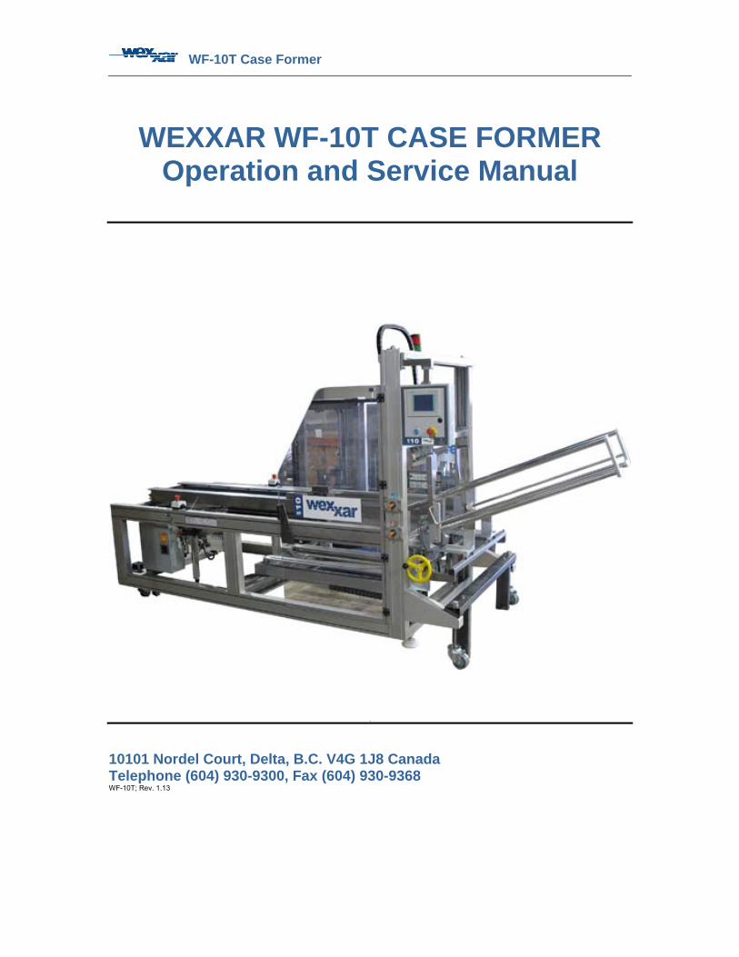
WF-10T Case Former WEXXAR WF-10T CASE FORMER Operation and Service Manual 10101 Nordel Court, Delta, B.C. V4G 1J8 Canada Telephone (604) 930-9300, Fax (604) 930-9368 WF-10T; Rev. 1.13
-
Upload
khangminh22 -
Category
Documents
-
view
0 -
download
0
Transcript of Wexxar/Bel WF20H Case Former Manual
WF-10T Case Former
WEXXAR WF-10T CASE FORMER
Operation and Service Manual
10101 Nordel Court, Delta, B.C. V4G 1J8 Canada Telephone (604) 930-9300, Fax (604) 930-9368 WF-10T; Rev. 1.13

WF-10T Case Former

WF-10T Case Former Table of Contents
i
Table of Contents
LIST OF TABLES............................................................................................................................ V TABLE OF FIGURES..................................................................................................................... VI PREFACE..................................................................................................................................... VIII
About this manual .................................................................................................................... ix How to use this manual ............................................................................................................x
1 SAFETY................................................................................................................................ 1-1 1.1 SAFETY CONSIDERATIONS............................................................................................... 1-2 1.2 SAFETY STANDARDS ....................................................................................................... 1-2 1.3 GENERAL PRECAUTIONS ................................................................................................. 1-2 1.4 LOCK-OUT PROVISION ..................................................................................................... 1-3 1.5 COMPRESSED AIR........................................................................................................... 1-3 1.6 ELECTRICAL POWER ....................................................................................................... 1-3 1.7 CONVEYOR DRIVEBELTS ................................................................................................. 1-3 1.8 GUARD DOORS AND SAFETY PLATING.............................................................................. 1-3 1.9 SAFETY INTERLOCKS........................................................................................................ 1-4 1.10 CAUTIONARY LABELS ...................................................................................................... 1-4 1.11 LUBRICANTS, ETC............................................................................................................ 1-4 1.12 SAFETY ORIENTED DESIGN ............................................................................................. 1-4
2 INSTALLATION ................................................................................................................... 2-5 2.1 PREREQUISITES .............................................................................................................. 2-5 2.2 SITE ENVIRONMENT CONSIDERATION............................................................................... 2-5 2.3 REMOVAL FROM CRATE................................................................................................... 2-6 2.4 INSTALLING THE WF-10T ................................................................................................ 2-6 2.5 LOCATION, LEVELING AND CONVEYORS............................................................................ 2-7
2.5.1 Location ................................................................................................................ 2-7 2.5.2 Leveling ................................................................................................................ 2-7 2.5.3 Discharge Conveyor ............................................................................................. 2-7
2.6 SERVICE CONNECTIONS .................................................................................................. 2-8 2.6.1 Compressed Air .................................................................................................... 2-8 2.6.2 Electrical Power .................................................................................................... 2-9 2.6.3 Installing the Tape Heads..................................................................................... 2-9
3 COMPONENT IDENTIFICATION ...................................................................................... 3-10 3.1 MAJOR COMPONENTS ................................................................................................... 3-14 3.2 PIN AND DOME TECHNOLOGY ........................................................................................ 3-17
4 THEORY OF OPERATION ................................................................................................ 4-18 4.1 SEQUENCE OF OPERATIONS .......................................................................................... 4-18 4.2 SENSORS & CABLES ..................................................................................................... 4-21
4.2.1 Inductive Sensors ............................................................................................... 4-21 4.2.2 Optical Sensors .................................................................................................. 4-21 4.2.3 Interlock Switches............................................................................................... 4-22 4.2.4 Sensor Cables .................................................................................................... 4-22
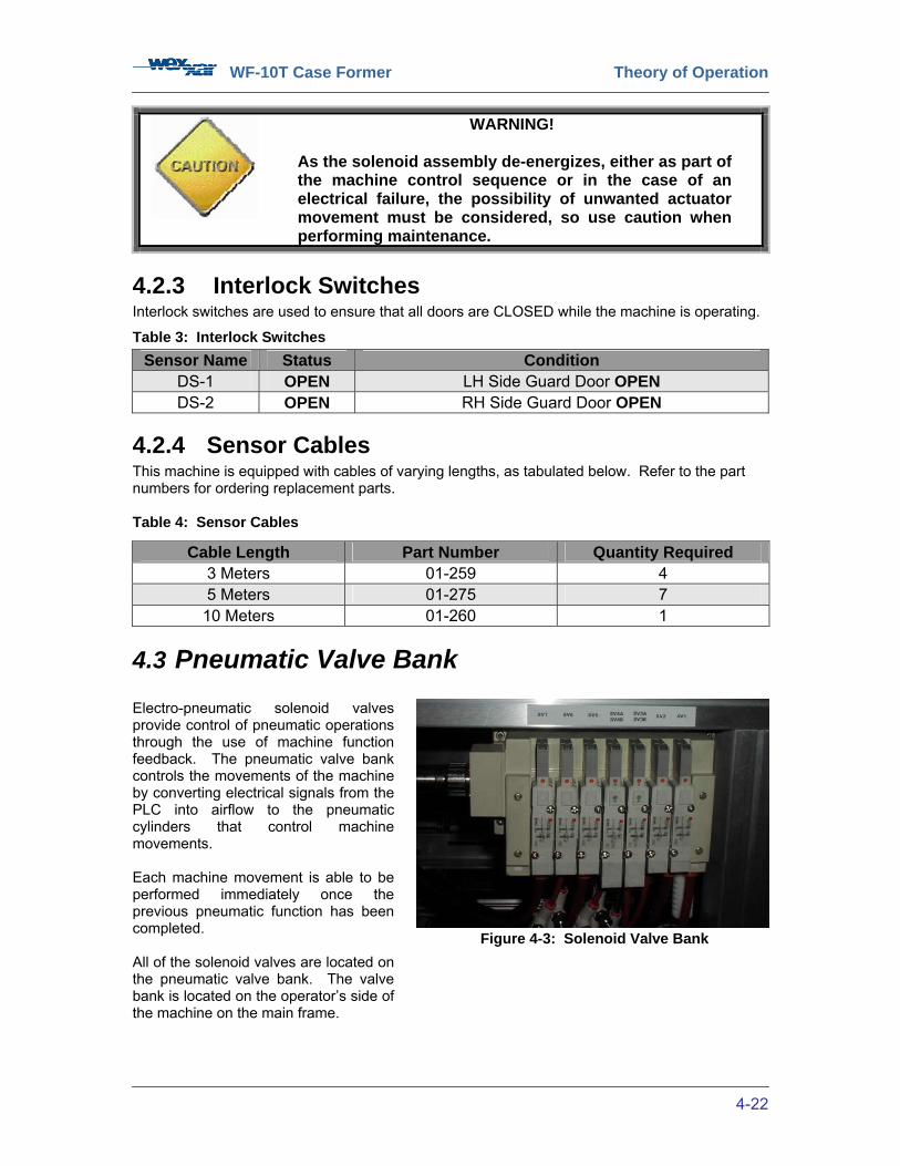
4.3 PNEUMATIC VALVE BANK............................................................................................... 4-22
WF-10T Case Former Table of Contents
ii
5 CONTROLS........................................................................................................................ 5-23 5.1 CONTROLS OVERVIEW .................................................................................................. 5-23 5.2 CONTROLS DESCRIPTION .............................................................................................. 5-23 5.3 AUTOMATIC CYCLE MODE........................................................................................ 5-26 5.4 JOG MODE .................................................................................................................. 5-28 5.5 DRY CYCLE MODE ..................................................................................................... 5-29 5.6 BOX CALL MODE ........................................................................................................ 5-31 5.7 CASE ORIENTATION CHANGES....................................................................................... 5-32
5.7.1 Case Orientation Change-over Procedure ......................................................... 5-34 6 OPERATING PROCEDURES............................................................................................ 6-40
6.1 SAFETY ........................................................................................................................ 6-40 6.2 START-UP..................................................................................................................... 6-41
6.2.1 Preliminary Checks............................................................................................. 6-41 6.2.2 Start-up Procedures............................................................................................ 6-42
6.3 MONITORING................................................................................................................. 6-44 6.3.1 Monitoring Machine Operation ........................................................................... 6-44 6.3.2 Loading the Magazine ........................................................................................ 6-44 6.3.3 Magazine Pushers .............................................................................................. 6-45
6.4 CLEARING A CASE JAM.................................................................................................. 6-47 6.5 SHUTDOWN .................................................................................................................. 6-48
7 CASE SIZE ADJUSTMENTS............................................................................................. 7-49 7.1 SAFETY ........................................................................................................................ 7-49 7.2 MACHINE ADJUSTMENTS ............................................................................................... 7-50 7.3 CASE SIZE ADJUSTMENT INSTRUCTION LABELS .............................................................. 7-51 7.4 CASE DIMENSION MEASUREMENTS................................................................................ 7-52 7.5 CASE SIZE RANGE ........................................................................................................ 7-53 7.6 CASE BLANK LENGTH DIMENSION ‘A’ ADJUSTMENT ........................................................ 7-54 7.7 BOTTOM FLAP HEIGHT DIMENSION ‘M’ ADJUSTMENT ...................................................... 7-55 7.8 CASE BLANK HEIGHT DIMENSION ‘B’ ADJUSTMENT ......................................................... 7-56 7.9 JAWPLATE CASE WIDTH DIMENSION ‘D1’ ADJUSTMENT................................................... 7-57
7.9.1 Horizontal Pinblock Adjustments ........................................................................ 7-60 7.9.2 Pinblock Mounting Orientation............................................................................ 7-62 7.9.3 Bottom Carriage Jawplate Pin & Dome Position Adjustments ........................... 7-63
7.10 CENTER SKI CASE WIDTH DIMENSION ‘D2’ ADJUSTMENT................................................ 7-64 7.11 CONVEYOR CASE WIDTH DIMENSION ‘D3’ ADJUSTMENT ................................................. 7-65 7.12 CARRIAGE CASE LENGTH DIMENSION C ADJUSTMENT .................................................... 7-66 7.13 TESTING THE SIZE ADJUSTMENTS .................................................................................. 7-67 7.14 QUICK SIZE CHANGE GUIDE .......................................................................................... 7-69
8 MACHINE MAINTENANCE ............................................................................................... 8-70 8.1 SAFETY ........................................................................................................................ 8-70 8.2 SERVICE AND MAINTENANCE PROCEDURES.................................................................... 8-71
8.2.1 Uni-Drive Side-Belt Drive System....................................................................... 8-71 8.2.2 Chain Drive ......................................................................................................... 8-71 8.2.3 Conveyor Side-Belt Replacement ...................................................................... 8-72 8.2.4 Gear Reducer ..................................................................................................... 8-72 8.2.5.................................................................................................................................... 8-73
8.3 MAINTENANCE .............................................................................................................. 8-73 8.3.1 Non-Lube Pneumatic System Maintenance ....................................................... 8-73 8.3.2 Inspections.......................................................................................................... 8-73 8.3.3 Routine Operator Maintenance .......................................................................... 8-74 8.3.4 Cleaning.............................................................................................................. 8-74

WF-10T Case Former Table of Contents
iii
8.4 PREVENTATIVE MAINTENANCE SCHEDULE...................................................................... 8-75 8.5 MAINTENANCE ADJUSTMENTS........................................................................................ 8-77
8.5.1 Mechanism Speeds ............................................................................................ 8-77 8.5.2 Shock Absorbers ................................................................................................ 8-77 8.5.3 Conveyor Belt Tension & Tracking ..................................................................... 8-77 8.5.4 Tape Head Adjustments ..................................................................................... 8-78 8.5.5 Pneumatic Supply Adjustments.......................................................................... 8-78 8.5.6 Proximity Sensors............................................................................................... 8-78 8.5.7 Mechanical Maintenance.................................................................................... 8-79
8.6 LUBRICATION ................................................................................................................ 8-79 8.6.1 Moving Components........................................................................................... 8-79 8.6.2 Ball Bearings....................................................................................................... 8-79 8.6.3 Tape Head .......................................................................................................... 8-79
9 TROUBLESHOOTING & REPAIRS .................................................................................. 9-80 9.1 SAFETY ........................................................................................................................ 9-80 9.2 GENERAL TROUBLESHOOTING ....................................................................................... 9-81 9.3 MACHINE SEQUENCE TROUBLESHOOTING ...................................................................... 9-83 9.4 ELECTRICAL TROUBLESHOOTING ................................................................................... 9-85 9.5 PNEUMATIC TROUBLESHOOTING .................................................................................... 9-86 9.6 CORRUGATED CASE QUALITY TROUBLESHOOTING ......................................................... 9-87 9.7 CASE DRIVEBELT SYSTEM TROUBLESHOOTING............................................................... 9-88
9.7.1 Case Not Sealing Squarely ................................................................................ 9-88 9.7.2 Crushed Band on Bottom of Case’s Side Panels............................................... 9-88 9.7.3 Belt Sheds Rubber ‘Dust’.................................................................................... 9-88 9.7.4 Conveyor Drive Rattles Audibly.......................................................................... 9-88 9.7.5 Cases Jam Frequently Between Belts................................................................ 9-89 9.7.6 Frequent Belt Breakage...................................................................................... 9-89
9.8 BOTTOM FLAP FOLDING TROUBLESHOOTING .................................................................. 9-90 9.8.1 Rear Minor Flap Does Not Fold.......................................................................... 9-90 9.8.2 Rear Flap Folds, Releases, and Turns Backwards ............................................ 9-90 9.8.3 Bottom Major Flaps Bind On Center Ski............................................................. 9-90 9.8.4 Major Flaps Overlap in Center of Case .............................................................. 9-90 9.8.5 Bottom Major Flaps Have a Gap in Center......................................................... 9-90 9.8.6 Major Flap Leading Edges Wrinkle After Taping................................................ 9-90 9.8.7 Major Flaps Have a Tapered Gap or Gap / Overlap Combination ..................... 9-91 9.8.8 Major Flaps Fold, but Leading Edge Lifted by Tape and Folded Back .............. 9-91
9.9 GENERAL TAPE APPLICATOR TROUBLESHOOTING........................................................... 9-92 9.9.1 Tape Does Not Stick To Case Surface............................................................... 9-92 9.9.2 Tape is not Cut Uniformly ................................................................................... 9-93 9.9.3 Tape Tail does not Stick Down Properly ............................................................ 9-93 9.9.4 Tape is Off-center ............................................................................................... 9-94 9.9.5 Tape Falls Forward on Tape Head..................................................................... 9-94
9.10 REPAIR PROCEDURES................................................................................................... 9-94 9.10.1 Solenoid Valve Repairs ...................................................................................... 9-94 9.10.2 Conveyor Drivebelt Repairs................................................................................ 9-95 9.10.3 Drivebelt Bearings Repairs................................................................................. 9-95 9.10.4 Gearmotor Repairs ............................................................................................. 9-95
WF-10T Case Former Table of Contents
iv
10 ENGINEERING SPECIFICATIONS ............................................................................. 10-96 10.1 OPERATING PARAMETERS ........................................................................................... 10-96
11 TRAINING GUIDE........................................................................................................ 11-97 11.1 PERFORMANCE CHECKLISTS ....................................................................................... 11-97 11.2 INSTRUCTIONS FOR ASSESSING PERFORMANCE ........................................................... 11-98
12 SERVICE & WARRANTY ............................................................................................ 12-99 13 OPTIONS.................................................................................................................... 13-100
13.1 TAPE MONITORING SYSTEM ...................................................................................... 13-100 14 INDEX......................................................................................................................... 14-101 APPENDIX A............................................................................................................................... 104
Material Safety Data Sheets: Fuchs Lubricants – Geralyn FMG 387 ................................. 104 APPENDIX B............................................................................................................................... 112
Material Safety Data Sheets: Keystone Lubricants – Nevastane HT-2............................... 112

WF-10T Case Former List of Tables
v
List of Tables Table 1: Inductive Sensors ........................................................................................................ 4-21 Table 2: Photosensors............................................................................................................... 4-21 Table 3: Interlock Switches........................................................................................................ 4-22 Table 4: Sensor Cables ............................................................................................................. 4-22 Table 5: Preliminary Start-up Checklist ..................................................................................... 6-42 Table 6: Mechanism HOME Positions and Valve Numbers...................................................... 6-42 Table 7: Machine Start-up Procedures...................................................................................... 6-43 Table 8: Machine Loading Checklist ......................................................................................... 6-46 Table 9: Clearing Jams.............................................................................................................. 6-47 Table 10: Machine Shutdown.................................................................................................... 6-48 Table 11: Case Size Range....................................................................................................... 7-53 Table 12: Dimension ‘A’ Adjustments........................................................................................ 7-54 Table 13: Dimension ‘M’ Adjustments ....................................................................................... 7-55 Table 14: Dimension ‘B’ Adjustments........................................................................................ 7-56 Table 15: Dimension ‘D1’ Adjustments ..................................................................................... 7-59 Table 16: Horizontal Pinblock Adjustments............................................................................... 7-61 Table 17: Pinblock Mounting Orientation .................................................................................. 7-62 Table 18: Dimension ‘D2’ Adjustments ..................................................................................... 7-64 Table 19: Dimension ‘D3’ Adjustments ..................................................................................... 7-65 Table 20: Dimension ‘C’ Adjustments ....................................................................................... 7-67 Table 21: Full Cycle Sequence.................................................................................................. 7-68 Table 22: Dimension Adjustment Reference............................................................................. 7-69 Table 23: Machine Inspection.................................................................................................... 8-73 Table 24: Routine Operator Maintenance ................................................................................. 8-74 Table 25: Cleaning the Machine................................................................................................ 8-75 Table 26: General Troubleshooting Reference ......................................................................... 9-82 Table 27: Machine Sequence Troubleshooting......................................................................... 9-83 Table 28: General Pneumatic Troubleshooting Reference ....................................................... 9-86 Table 29: Cylinders too slow ..................................................................................................... 9-86 Table 30: Cylinders not moving ................................................................................................. 9-87 Table 31: Operating Parameters ............................................................................................. 10-96 Table 32: Performance Checklists........................................................................................... 11-97
WF-10T Case Former Table of Figures
vi
Table of Figures Figure 1-1: Locked Out Electrical Disconnect and Filter-Regulator Assembly ........................... 1-3 Figure 1-2: Example of Safety Interlock ...................................................................................... 1-4 Figure 1-3: Sample Cautionary Label.......................................................................................... 1-4 Figure 2-1: Filter-Regulator Assembly......................................................................................... 2-8 Figure 3-1: Case Former Operator’s Side View ........................................................................ 3-10 Figure 3-2: Carriage Return Shocks Absorbers and Sensor..................................................... 3-11 Figure 3-3: Flap Folding Section Components.......................................................................... 3-11 Figure 3-4: Injector, Caliper, and Sensors................................................................................. 3-12 Figure 3-5: Walk-In Magazine Assembly................................................................................... 3-12 Figure 3-6: Carriage and Jawplate Assemblies......................................................................... 3-13 Figure 4-1: Injector Down; Pins Penetrating Corrugate Flutes.................................................. 4-19 Figure 4-2: Rear Flap Folder Kicker Arm Actuated ................................................................... 4-19 Figure 4-3: Solenoid Valve Bank............................................................................................... 4-22 Figure 5-1: Main Disconnect Switch.......................................................................................... 5-23 Figure 5-2: ‘RESET’ Button ....................................................................................................... 5-23 Figure 5-3: ‘EMERGENCY STOP’ Buttons ............................................................................... 5-23 Figure 5-4: 'Service' Screen ...................................................................................................... 5-24 Figure 5-5: 'Main Control' Screen.............................................................................................. 5-24 Figure 5-6: 'Main Control' Button ............................................................................................... 5-25 Figure 5-7: Machine in AUTOMATIC CYCLE Mode .................................................................. 5-25 Figure 5-8: ‘START’ Button ....................................................................................................... 5-25 Figure 5-9: ‘STOP’ Button ......................................................................................................... 5-25 Figure 5-10: 'LARGE BOX / SMALL BOX’ Button..................................................................... 5-26 Figure 5-11: 'Box Setup' Screen................................................................................................ 5-26 Figure 5-12: Box Size Selection Button..................................................................................... 5-26 Figure 5-13: Changing the Box Size.......................................................................................... 5-27 Figure 5-14: SMALL BOX Selected........................................................................................... 5-27 Figure 5-15: 'Box Setup Jogging On' Button ............................................................................. 5-27 Figure 5-16: 'Previous' Button ................................................................................................... 5-27 Figure 5-17: 'JOG CONTROL' Button ....................................................................................... 5-27 Figure 5-18: ‘Jog Control’ Screen.............................................................................................. 5-28 Figure 5-19: JOG CONTROL Status Indicator Illuminated........................................................ 5-28 Figure 5-20: Sensor Status Indicator......................................................................................... 5-28 Figure 5-21: 'MACHINE CYCLE JOG' Button ........................................................................... 5-28 Figure 5-22: 'SETUP' Button ..................................................................................................... 5-28 Figure 5-23: 'Setup' Screen ....................................................................................................... 5-29 Figure 5-24: DRY CYCLE OFF/ON Toggle Switch ................................................................... 5-29 Figure 5-25: DRY CYCLE ACTIVE Indicator............................................................................. 5-29 Figure 5-26: DRY CYCLE Function........................................................................................... 5-29 Figure 5-27: 'REMOTE DEMAND OFF/ON’ Toggle Switch ...................................................... 5-30 Figure 5-28: REMOTE DEMAND Indicator ............................................................................... 5-30 Figure 5-29: REMOTE DEMAND Function ............................................................................... 5-30 Figure 5-30: Remote Demand Sensor ...................................................................................... 5-30 Figure 5-31: 'BOX CALL’ Button................................................................................................ 5-31 Figure 5-32: 'REMOTE DEMAND OFF/ON’ Toggle Switch ...................................................... 5-31 Figure 5-33: REMOTE DEMAND Indicator ............................................................................... 5-31 Figure 5-34: BOX CALL Function.............................................................................................. 5-31 Figure 5-35: Right-handed Case Orientation ............................................................................ 5-33 Figure 5-36: 'Case Orientation’ Toggle Switch.......................................................................... 5-34 Figure 5-37: Case Orientation Toggle Switch ........................................................................... 5-35 Figure 5-38: Case Orientation 'Handing' Change-over ............................................................. 5-35 Figure 5-39: 'ALARM HISTORY' Button.................................................................................... 5-36

WF-10T Case Former Table of Figures
vii
Figure 5-40: 'Alarm History' Screen........................................................................................... 5-36 Figure 5-41: 'CLEAR' Button ..................................................................................................... 5-36 Figure 5-42: ‘Password’ Window............................................................................................... 5-36 Figure 5-43: 'Alphanumeric Keypad’ Window............................................................................ 5-36 Figure 5-44: ‘PREVIOUS’ Button............................................................................................... 5-36 Figure 5-45: 'Service' Button ..................................................................................................... 5-37 Figure 5-46: 'TROUBLESHOOTING’ Button............................................................................. 5-37 Figure 5-47: 'Troubleshooting' Screen ...................................................................................... 5-37 Figure 5-48: 'PLC INPUTS’ Button ............................................................................................ 5-37 Figure 5-49: 'PLC Inputs’ Screen .............................................................................................. 5-38 Figure 5-50: 'PLC Inputs’ Status Indicator................................................................................. 5-38 Figure 5-51: PLC Input Status Indicator Illuminated.................................................................. 5-38 Figure 5-52: 'PLC OUTPUTS’ Button ........................................................................................ 5-38 Figure 5-53: 'PLC Outputs' Screen............................................................................................ 5-39 Figure 5-54: 'PLC Outputs’ Status Indicator .............................................................................. 5-39 Figure 5-55: PLC Output Function Indicator Illuminated ........................................................... 5-39 Figure 6-1: Walk-In Magazine ................................................................................................... 6-44 Figure 6-2: Magazine Pusher .................................................................................................... 6-45 Figure 6-3: Magazine Pusher in Locked Position...................................................................... 6-45 Figure 6-4: Discharge Pusher Before and After Adjustment ..................................................... 6-45 Figure 6-5: Discharge Pusher Adjustment Wingnuts ................................................................ 6-45 Figure 7-1: Case Size Adjustment and Jawplate Adjustment Instruction Labels...................... 7-51 Figure 7-2: Case Dimension Measurements............................................................................. 7-52 Figure 7-3: Case Size Range Dimensional Diagram................................................................. 7-53 Figure 7-4: Dimension ‘A’ Hand Crank...................................................................................... 7-54 Figure 7-5: Dimension ‘A’ Pointer.............................................................................................. 7-54 Figure 7-6: Magazine Width ...................................................................................................... 7-54 Figure 7-7: Vertical Adjustment Chain Lock .............................................................................. 7-55 Figure 7-8: Dimension ‘M’ Hand Crank ..................................................................................... 7-55 Figure 7-9: Dimension ‘M’ Pointer ............................................................................................. 7-55 Figure 7-10: Dimension ‘B’ Vertical Adjustment Chain Lock..................................................... 7-56 Figure 7-11: Dimension ‘B’ Pointer on Injector Backplate......................................................... 7-56 Figure 7-12: Dimension ‘B’ Hand Crank.................................................................................... 7-56 Figure 7-13: Dimension ‘D1’ Hand Crank.................................................................................. 7-57 Figure 7-14: Dimension ‘D1’ Pointer.......................................................................................... 7-57 Figure 7-15: Measuring Parallel Jawplate Width....................................................................... 7-57 Figure 7-16: Jawplate Formed Case Width 'D1' Adjusts ........................................................... 7-58 Figure 7-17: Improperly Adjusted Synchronizer Bar ................................................................. 7-58 Figure 7-18: Properly Adjusted Synchronizer Bar ..................................................................... 7-58 Figure 7-19: Divergent Jawplates.............................................................................................. 7-58 Figure 7-20: Parallel Jawplates ................................................................................................. 7-58 Figure 7-21: Jawplate and Carriage Assemblies....................................................................... 7-60 Figure 7-22: Ringpins and Horizontal Pinblock Adjustment Wingnuts ...................................... 7-60 Figure 7-23: Outer (left) and Inner (right) Pins Engaged........................................................... 7-62 Figure 7-24: Pin & Dome Position Adjustments ........................................................................ 7-63 Figure 7-25: Clearance Between Rear Flap and Center Ski..................................................... 7-64 Figure 7-26: Bottom Center Ski ................................................................................................. 7-64 Figure 7-27: Dimension ‘D3’ Case Width Adjust ....................................................................... 7-65 Figure 7-28: Case Width Verification......................................................................................... 7-65 Figure 7-29: Dimension ‘C’ Formed Case Length Adjust .......................................................... 7-66 Figure 7-30: Jawplate and Carriage Assemblies....................................................................... 7-66 Figure 8-1: Serpentine Chain Drive........................................................................................... 8-71 Figure 8-2: Conveyor Belt Tensioning....................................................................................... 8-77 Figure 8-3: Inductive Sensor Adjustment Range....................................................................... 8-78 Figure 9-1: Lowering the Tape Head Bracket ........................................................................... 9-89 Figure 9-2: Elevating the Tape Head Bracket ........................................................................... 9-91

WF20H Case Former Preface
viii
PREFACE WEXXAR Model WF-10T Case Formers are versatile and industry-proven machines with unique mechanical case forming and bottom-flap folding technology. These machines offer maximum flexibility and performance within a broad range of case styles and sizes, and have available a choice of options to meet your own specific requirements. Please read this Operation & Service Manual carefully, as it contains the necessary information required to extend the service life of this machine to its fullest. Furthermore, this manual will inform you regarding the correct and safe usage of this machine. We recommend that you keep this manual with the case former for future reference. If any problems are encountered with the procedures contained in this manual, please contact our Service Center before proceeding. While every effort has been made to ensure the completeness and accuracy of this manual, WEXXAR assumes no responsibility or liability for any losses or damages resulting from the use of the information contained in this document. Due to technical advances and improvements, some of the information contained in this manual may be changed or modified without prior notice from WEXXAR/BEL. The WF-10T Case Former Operation and Service Manual was written to assist you in installing, operating, troubleshooting, maintaining, repairing, and training others to operate the machines properly. This manual describes the standard features that are present in WF-10T machines, along with a few of the most common optional features. For information specific to your machine, please refer to the custom-made Supplementary Manual and material that accompanies this guide. This document may not be copied or reproduced without the explicit permission of WEXXAR/BEL.
WF20H Case Former Preface
ix
About this manual Although this manual is not a series of regulations, it contains guidance that will make the use of the WF-10 Series machines simple and safe. The manual has 13 chapters, as well as 2 appendices, listed below: Chapter 1 describes the safety guidelines required for machine operation, maintenance and servicing. Chapter 2 provides recommended installation procedures, including unpacking and inspection, site environment consideration, location, spacing requirements, assembly instructions, and electrical connections. Chapter 3 provides an explanation of the major pneumatic, mechanical and electrical components. Chapter 4 explains the machine’s theory of operation, including electronic, pneumatic, and mechanical functions. Chapter 5 explains all major equipment operation functions and procedures, including preliminary checks, start-up procedures, shutdown procedures and instructions for clearing jams. Chapter 6 provides a detailed explanation of the Human-Machine Interface (HMI) LCD touchscreen control system, which controls all electronic and pneumatic machine functions with the exception of manual override buttons and safety interlocks. Chapter 7 deals with machine calibration and case size adjustments, as well as testing and troubleshooting. Chapter 8 is for users who maintain equipment or systems. It provides the safety guidelines, a maintenance schedule, the procedures for maintenance and lubrication, and a list of maintenance parts. Chapter 9 is for qualified repair technicians, and provides them with safety guidelines to follow when undertaking any repairs. It explains the warranty and services that accompany Model WF-10T machines. It also describes advanced troubleshooting and repair procedures, and lists the repair parts. It is written for users who design and modify equipment. Please note that modifications to the equipment may void your warranty. Chapter 10 provides detailed specifications required for machine set-up, maintenance and repair, and troubleshooting. Chapter 11 is intended for users who train others how to operate and maintain the WF-10 Series machines. It includes references to instructor data sheets throughout the manual, and provides performance checklists. Chapter 12 explains WEXXAR/BEL product support policies and practices, as well as important warranty information. Chapter 13 provides a comprehensive index of terms commonly used in this manual. Appendices A and B provide comprehensive Material Safety Data Sheets for the machine’s various recommended lubricants and adhesive solutions for your protection.

WF20H Case Former Preface
x
How to use this manual Please note that some of the images in this manual may differ slightly from your machine.
You will also be alerted that you must stop and read the instructions carefully using the following symbol.
Throughout this manual, you will find three safety symbols: The names of all buttons, keys, sensors, switches, and status indicators are capitalized, boldfaced, and placed in single quotes.
For example, “Press the ‘START’ button.” All machine component status terms, operations, functions, displays, and features are capitalized and boldfaced.
For example, “The case separator returns to the UP position.” When referring to sections in this manual, we italicize the link and use single quotes.
For example, See Section 6: ‘Operating Procedures’. Please note that some of the some of the pictures in this manual may differ slightly from your machine.
This symbol alerts you to a risk of personal injury due to mechanical or pneumatic operation.
This symbol indicates that an electrical hazard may be present. It may be used in lieu of the wording ‘caution, risk of electric shock’ for any cautionary marking.
This symbol alerts you to general risks not associated with electrical, pneumatic or mechanical operations, or indicates that an action could cause equipment damage or affect the quality of the product.
This symbol is used to alert you of an important step in operational sequence, to note exceptions to normal machine operation, or when special circumstances must be taken into consideration by the machine operator.
WF-10T Case Former Safety
1-1
1 SAFETY
MUST BE READ PRIOR TO OPERATING
The WF-10T has safety features to prevent you from injury while the machine is operating. Guard doors equipped with interlock switches prevent you from entering the work cell while the case formation is in progress; the machine will not run if these doors are open. The electrical enclosure access door must also be closed in order for the machine to operate. The perimeter guarding system surrounds the area known as the restrictive envelope and covers the entire range of possible machine motion. For your safety, you should never try to bypass the perimeter guarding system or enter the restrictive envelope while the machine is in operation. There are three ‘EMERGENCY STOP’ buttons that immediately halt all machine operations by cutting off air supply and electrical power. These buttons should be pushed IN to stop the machine in case of an emergency.
WARNING!
The instructions in this manual are not intended to cover all of the details or variations in equipment, or to provide for every possible contingency to be met in connection with installation, operation, or maintenance. Should further information be desired, or should particular problems arise which are not covered sufficiently for the purchaser’s purposes, the matter should be referred directly to WEXXAR/BEL.
WARNING!
Any electrical or mechanical modifications to this equipment without the prior consent of WEXXAR/BEL may void your warranty. Unauthorized modifications can also result in personal injury, death, or destruction of the equipment.
WF-10T Case Former Component Identification
1-2
1.1 Safety Considerations WEXXAR/BEL is proud to employ every conceivable precaution in the research and development of our case formers. Our commitment to workplace safety has made us a world-class leader in the packaging industry due to our adoption of the following best practices:
• Fully automatic functionality, requiring minimal operator interaction
• Advanced safety guarding with keyed electronic safety interlock switches
• Lock-out provision on electrical and pneumatic main shut-offs
• Intuitive cautionary labeling demonstrating electrical and mechanical risks
• E-STOP shutdown, with two auxiliary ‘E-STOP’ buttons
• PLC operated sequence and timing control
1.2 Safety Standards WEXXAR/BEL observes the following safety standards:
• ANSI B151.1-2000 Safety Standards for Mechanical Power Transmission Apparatus
• CSA C22.2.1-02; 0-M91 Canadian Electrical Code Part I and Part II
• NFPA 79 Electrical Standards for Industrial Machines
• CSA C22.2 No. 14-95 Industrial Control Equipment
• ANSI Z535.4-2002 Product Safety Signs & Labels
• ANSI B155.1-2000 for Packaging Machinery
• NEMA 12 UL listed standard electrical control
1.3 General Precautions Your WEXXAR packaging machine is a rugged piece of industrial machinery. It is equipped with various guards and other safety features, but it must be treated with respect at all times to avoid the possibility of personal injury. The following points are particularly important:
• Do not operate the machine until it is completely set up and installed properly, and you are familiar with its operation.
• Do not operate machine without guards and safety mechanisms in place and functioning.
• Do not attempt to enter the machine for any reason while the air pressure is still on.
• Do not wear neckties, jewelry, loose clothing, or other items that can get caught in moving parts or mechanisms near the machine.
• Do not operate, troubleshoot, or maintain the machine while under the influence of any type of drug or alcohol.
• Always observe all safety warnings and notices on the machine and in this manual.
• Do not use solvents when cleaning or maintaining the machine.
• All installation wiring must comply with applicable local codes.

WF-10T Case Former Component Identification
1-3
1.4 Lock-out Provision The WF-10T is lock-out / tag-out compliant on both the electrical and pneumatic main shut-offs. Both the main electrical disconnect and the filter-regulator assembly can be locked out on our WEXXAR Case Formers. Ensure that you lock out the machine and adhere strictly to the safety precautions listed in Section 6.2.1: ‘Preliminary Checks’ prior to performing any repairs or maintenance.
1.5 Compressed Air Compressed air is used to power the movement of many machine motions. You must be sure that the machine's main air solenoid valve is shut off before attempting to clear jams or make minor adjustments which require you to get close to the moving parts of the machine. This air valve shuts off when the guard doors are opened, or when the main power is switched off. To safely carry out service or repair work on the machine, a lockable shutoff valve is located on all WEXXAR machines upstream of the filter-regulator unit. Padlock this valve in the OFF position for absolute safety during service work. Always follow local lock-out/tag-out regulations. Always exercise caution when switching the compressed air back ON. Stay well clear of all moving parts, as they may move quickly when the pressure is reapplied. Make sure that no other people are in a dangerous position when switching the compressed air on.
1.6 Electrical Power The main supply voltage for the WF-10T is 120V 60Hz single-phase. Switch off the main power disconnect switch located on the control panel, and lock it out before attempting service work outside of the electrical enclosure. Before performing service work inside of the electrical enclosure, disconnect all electrical power to the machine (customer supplied disconnect).
1.7 Conveyor Drivebelts Where used, the optional outfeed conveyor drivebelt systems used on WEXXAR packaging machines operate at moderate speeds. Be sure to keep fingers well clear of all moving parts, as the gearmotor develops substantial torque, and does not stop easily. Do not wear loose clothing, jewelry, or accessories (e.g., neckties) when operating WEXXAR packaging machines.
1.8 Guard Doors and Safety Plating WEXXAR/BEL takes your safety seriously, offering the added benefit of safety guarding on all of our WF Series units, which prevent operators from reaching into the machine during routine operation and maintenance.
Figure 1-1: Locked Out Electrical Disconnect and Filter-Regulator
Assembly
WF-10T Case Former Component Identification
1-4
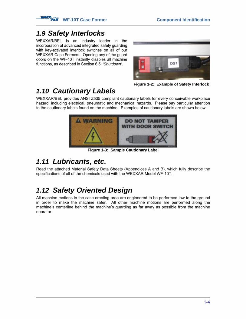
1.9 Safety Interlocks WEXXAR/BEL is an industry leader in the incorporation of advanced integrated safety guarding with key-activated interlock switches on all of our WEXXAR Case Formers. Opening any of the guard doors on the WF-10T instantly disables all machine functions, as described in Section 6.5: ‘Shutdown’.
1.10 Cautionary Labels WEXXAR/BEL provides ANSI Z535 compliant cautionary labels for every conceivable workplace hazard, including electrical, pneumatic and mechanical hazards. Please pay particular attention to the cautionary labels found on the machine. Examples of cautionary labels are shown below.
Figure 1-3: Sample Cautionary Label
1.11 Lubricants, etc. Read the attached Material Safety Data Sheets (Appendices A and B), which fully describe the specifications of all of the chemicals used with the WEXXAR Model WF-10T.
1.12 Safety Oriented Design All machine motions in the case erecting area are engineered to be performed low to the ground in order to make the machine safer. All other machine motions are performed along the machine’s centerline behind the machine’s guarding as far away as possible from the machine operator.
Figure 1-2: Example of Safety Interlock

WF-10T Case Former Installation
2-5
2 INSTALLATION 2.1 Prerequisites To install the WEXXAR WF-10T Case Former you will require:
• A forklift truck to remove the machine from the skid.
• A spirit level to level the machine.
• Compressed air and electrical power supplies.
2.2 Site Environment Consideration Before receiving the machine, consider the physical environment that the machine will operate in. Consider the following factors before transporting, unpacking, installing, or setting up the machine. • The machine operator is required to guarantee that the temperature and humidity values
of the site into which the machine will be installed meet the required and published manufacturer specifications. The machine should be installed within the range allowed by these specifications.
• This machine is intended for use in a controlled indoor environment free of conductive
contaminants. • Do not let the any areas of the unit adjacent to electrical components come in contact
with water. • Do not stand beverage containers on the electrical panel, or on any surface adjacent to
electrical components. • This system is not intended for external use unless it has been specifically modified for
that purpose. • This unit is rated in accordance with national and local electrical codes. Make sure that
the wall outlet is also wired to these specifications. • The power supply for this unit:
1. Must be rated in accordance with the equipment data plate. 2. Must be suitably grounded.
• Do not place the machine near any heat source or machinery which may produce
metallic particles, dust or powder. Do not place the machine near equipment that will produce corrosive substances or vapor.
• Walls, ceilings, floors, or anything near to the machine should be constructed of
noncombustible materials. A portable fire extinguisher should be accessible nearby.
WF-10T Case Former Installation
2-6
2.3 Removal from Crate
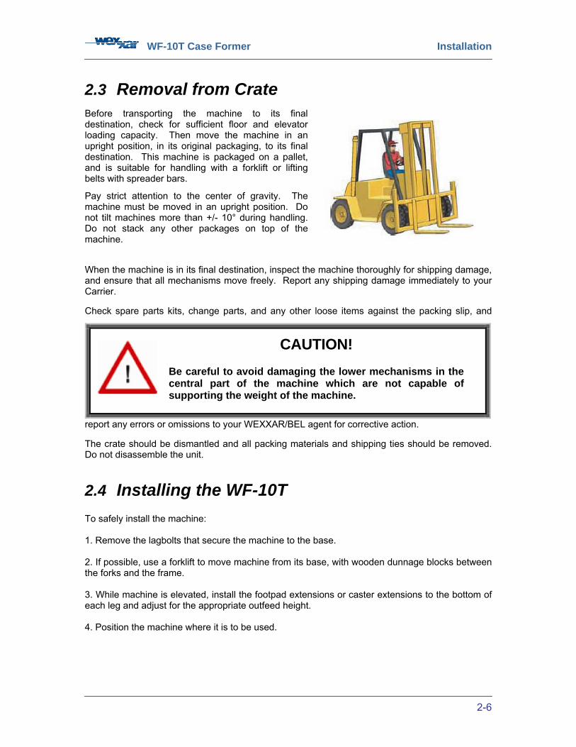
Before transporting the machine to its final destination, check for sufficient floor and elevator loading capacity. Then move the machine in an upright position, in its original packaging, to its final destination. This machine is packaged on a pallet, and is suitable for handling with a forklift or lifting belts with spreader bars.
Pay strict attention to the center of gravity. The machine must be moved in an upright position. Do not tilt machines more than +/- 10° during handling. Do not stack any other packages on top of the machine. When the machine is in its final destination, inspect the machine thoroughly for shipping damage, and ensure that all mechanisms move freely. Report any shipping damage immediately to your Carrier. Check spare parts kits, change parts, and any other loose items against the packing slip, and
report any errors or omissions to your WEXXAR/BEL agent for corrective action. The crate should be dismantled and all packing materials and shipping ties should be removed. Do not disassemble the unit.
2.4 Installing the WF-10T To safely install the machine: 1. Remove the lagbolts that secure the machine to the base. 2. If possible, use a forklift to move machine from its base, with wooden dunnage blocks between the forks and the frame. 3. While machine is elevated, install the footpad extensions or caster extensions to the bottom of each leg and adjust for the appropriate outfeed height. 4. Position the machine where it is to be used.
CAUTION!
Be careful to avoid damaging the lower mechanisms in the central part of the machine which are not capable of supporting the weight of the machine.
WF-10T Case Former Installation
2-7
2.5 Location, Leveling and Conveyors
2.5.1 Location When selecting the machine location, carefully consider the following points:
• Adequate access around the machine for correct operation and service.
• Sufficient room to open the guards and access doors (including control enclosure).
• A minimum 3-foot clearance in front of the main electrical enclosure.
• Easy lift-truck access.
• Good access for magazine loading and nearby space for pallet loads of flat cases.
2.5.2 Leveling • Use at least a two-foot carpenter level, marked on one end so that you always work to
the same bubble line and with the concave side down (if there is one).
• Open the guard doors, and position the spirit level along the length of the main frame to level one side of the machine.
• Adjust the machine leveling feet on this side of the machine as appropriate to centralize the bubble between the parallel lines.
• Position the spirit level on the main frame along the width of the machine at the discharge end.
• Adjust the machine leveling feet under the magazine and discharge ends on the opposite side in order to centralize the bubble between the parallels.
• Tighten the level adjuster lock nuts. • Anchor the machine to the floor.
The machine should be kept level in order to avoid frame stress and ensure optimum performance. An adjustable height footpad kit is included as standard equipment, and can be used to level the machine on an uneven floor. The machine should be anchored to adjoining equipment or to the floor in order to prevent any movement of the machine by reactive forces that may occur as sealed cases are being driven through the machine outfeed.
2.5.3 Discharge Conveyor The discharge conveyor is customer supplied and may be a gravity-fed or powered type. If the discharge conveyor is powered, a smooth top surface is preferred. It is important to note that the case discharge mechanism is designed to discharge the case against zero restraint. It is not intended to overcome the friction of a long conveyor filled with cases, or push cases up an inclined slope. Excessive discharge friction will cause improper machine operation.
CAUTION!
The machine should NOT be operated on casters.

WF-10T Case Former Installation
2-8
2.6 Service Connections
2.6.1 Compressed Air The WF-10T requires an air supply that must be clean and dry, and must not drop below 75 PSI to a maximum of 90 PSI. The air supply should be clean and dry, and the air-line should have a minimum inside diameter of 1/2”. The incoming air supply line must be of sufficient diameter to provide an adequate amount of air without the pressure dropping when the machine is cycling. One of the most common causes of inconsistent machine performance is inadequate air supply. Therefore, the foregoing requirements must be carefully observed in order to assure satisfactory operation. The WF-10T is equipped with a manual compressed air ON-OFF/dump valve, unless otherwise specified, and a filter-regulator that regulates the air pressure to the proper setting, and ensures that any water is drained from the filter. With the electrical power OFF, open the manual shutoff valve and check that the regulator is set to a pressure of 90 PSI. After connecting the electrical power (see Section 2.6.2), switch the electrical power ON; all cylinders should revert to their HOME positions, and there should be no evidence of air leaks. See Section 6.2: ‘Start-up’. To check that the pneumatic components of each mechanism are functioning properly, the solenoid valves may be operated mechanically.
Figure 2-1: Filter-Regulator Assembly
SAFETY NOTICE!
Service connections (electrical and pneumatic) should ONLY be undertaken by qualified personnel. Observe proper lock-out procedures and recommended sequence to avoid personal injury or damage to the machine.
WF-10T Case Former Installation
2-9
2.6.2 Electrical Power Before attempting any electrical connections, check the machine’s set-up voltage. This is listed on a label on the inside of the access panel of the electrical enclosure. The standard WEXXAR WF-10T voltage is 120V 60Hz 1-Phase, but alternate voltages are accommodated to meet specific customer requests.
Electrical power is required to be connected to the designated high voltage terminals on the side of the main electrical disconnect. The machine must also be properly grounded. All wiring must comply with applicable local codes. For a copy of the machine’s wiring diagram, refer to the drawings attached to this manual. When electrical power has been connected and all access doors are closed, switch the main disconnect switch ON. Check that all ‘EMERGENCY STOP’ buttons are in the OFF position. Press the ‘RESET’ button on the control panel. Press the ‘START’ button on the touchscreen. Refer to Section 5: ‘Controls’ for further information on machine controls. The drive motor should be ON. Verify the direction of the drive motor. Allow the machine to run for ten minutes to ensure that the factory preset motor overloads do not trip. Minor adjustments to these components may be necessary to compensate for voltage variations. A dedicated electrical circuit is recommended for this machine. Any electrical connections required before installing the machine must be conducted by an electrician qualified in your jurisdiction.
2.6.3 Installing the Tape Heads Tape dispensing heads are mounted with pins on their sides that fit into corresponding slots in the tape head mounting brackets. Machines are usually shipped with the tape head secured in its brackets. If it needs to be lowered into the brackets, align the pins on the side of the tape heads with the slots in the brackets as follows: On the tape head, slide the front pins on the head down and back into the key-shaped slots. The rear pins will then drop into the vertical slots on the bracket. The head is held in place by its own weight. Please consult the tape head manual for instructions on the mounting of tape rolls and the proper threading of tape through the applicator head.

WF-10T Case Former Component Identification
3-10
3 COMPONENT IDENTIFICATION
Figure 3-1: Case Former Operator’s Side View
Frame Arch
Electrical Enclosure
(Control Panel)
Side-belt Conveyors
Conveyor Width ‘D3’ Adjustment
Guard Door
Interlock Safety
Switches Carriage
Guide Track
Center Ski ‘D2’ Adjustment
Tape Head Bracket Slots
Carriage with Jawplate Width ‘D1’ Adjustment
Case Blank Height ‘B’
Adjustment
Uni-Drive Chain
(beneath guarding
Motor
Leveler (typical)
Filter-Regulator Assembly
Walk-In Magazine
Touchscreen
Bottom Flap Height ‘M’
Adjustment
Valve Bank (not
shown)
Case Blank Length ‘A’
Adjustment
Stack Light (position may
differ depending on machine
configuration)
PRS-11 Case In Sensor
PHS-15 Case Out Sensor
WF-10T Case Former Component Identification
3-11
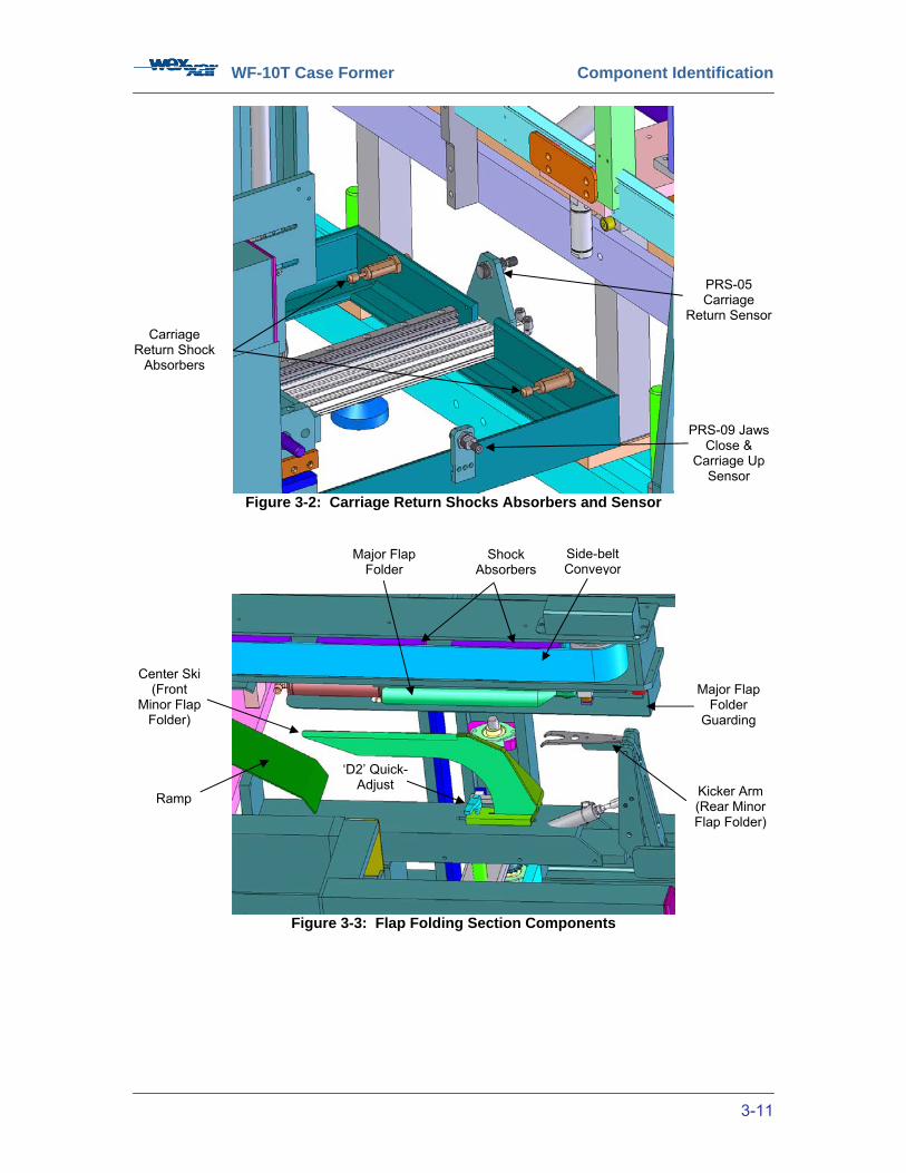
Figure 3-2: Carriage Return Shocks Absorbers and Sensor
Figure 3-3: Flap Folding Section Components
Carriage Return Shock
Absorbers
PRS-05 Carriage
Return Sensor
Major Flap Folder
Guarding
Major Flap Folder
Center Ski (Front
Minor Flap Folder)
Ramp
Side-belt Conveyor
PRS-09 Jaws Close &
Carriage Up Sensor
Shock Absorbers
Kicker Arm (Rear Minor Flap Folder)
‘D2’ Quick-Adjust

WF-10T Case Former Component Identification
3-12
Figure 3-4: Injector, Caliper, and Sensors
Figure 3-5: Walk-In Magazine Assembly
PRS-02 Injector Up
Sensor
PRS-03 Injector Down
Sensor
PHS-04 Case Separator Up
Sensor
Caliper Slot
Injector
Caliper
Magazine Pusher Locks
Infeed Supports
Hopper Guide Rails
Magazine Pushers
PRS-01 Empty Magazine
Sensor
WF-10T Case Former Component Identification
3-13
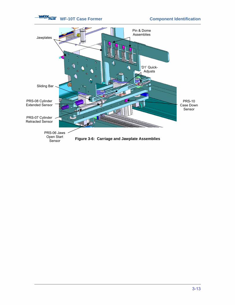
Figure 3-6: Carriage and Jawplate Assemblies
Pin & Dome Assemblies
Jawplates
Sliding Bar
‘D1’ Quick-Adjusts
PRS-10 Case Down
Sensor
PRS-06 Jaws Open Start
Sensor
PRS-07 Cylinder Retracted Sensor
PRS-08 Cylinder Extended Sensor
WF-10T Case Former Component Identification
3-14
3.1 Major Components 1) Calipers The Caliper is located at the infeed end of the magazine between the magazine assembly and the injector. The gap between the case injector and the calipers forms the caliper slot, which permits the separation of one case at a once. The width of the caliper slot is factory-set according to each client’s specific requirements and cannot be adjusted. 2) Case Blank Pushers (Magazine Pushers) The Case Blank Pushers are arms that apply a constant horizontal pressure to the cases in the hopper, holding case blanks upright and assisting in moving them forward towards the case separator by means of gravity. 3) Case Separator Located at the bottom end of the hopper, the Case Separator opposes the magazine pushers in order to hold the stacked cases securely. The upwards motion of the case separator moves the end case UP into the caliper slot, separating it from the rest of the stacked cases. 4) Control Panel Enclosure/Electrical Panel Enclosure Mounted on the operator’s side of the machine, the Control Panel Enclosure has the touchscreen interface (HMI: Human Machine Interface) and any other buttons and switches for operating the machine. It houses the PLC (Programmable Logic Controller) and other electrical components. All electrically operated user controls with the exception of the auxiliary emergency stops are located on the door of this enclosure. 5) DC Power Supply The DC Power Supply is a device that delivers 24V DC power for the machine’s control system. 6) Discharge (Outfeed) Conveyor The Discharge Conveyor advances cases to the next operation after case forming. This conveyor is not included with the machine; it can be included as an option, or it can be supplied by the customer. 7) Dome The Dome is a small, partly spherical component mounted on jawplates above the pins. The dome helps position the case material for proper insertion of the pins into the corrugate flutes for secure holding. 8) Drivebelts (Side-belt Conveyor) Two Drivebelts receive cases from the carriage and transport them past the tape applicator head and out to the (optional) discharge conveyor. 9) Electrical Disconnect The Electrical Disconnect is the electrical control panel’s main power switch, which can be padlocked OFF for safety. 10) Filter-Regulator Mounted on the operator’s side of the machine, the Filter-Regulator component filters and controls incoming compressed air. 11) Flap Folders The Flap Folders fold the bottom case flaps so that they are ready for sealing. They are composed of the rear flap folder ‘kicker arm’, the passive center ski, and two major flap folders.
WF-10T Case Former Component Identification
3-15
12) Gear Reducer The Gear Reducer lowers the speed of the drivebelts by reducing the speed of the standard electric motor. 13) Hinged Guard Door The Hinged Guard Doors provide access to the forming area of the machine. The machine immediately stops if any of these doors are opened during operation. 14) Hopper The magazine on the WF-10T, located at the input end of the machine, also serves as a gravity-fed Hopper, a storage area that holds stacked, flat case blanks, and advances them to be processed. Due to their dual function, the words ‘hopper’ and ‘magazine’ are used synonymously throughout the manual where applicable. 15) Hopper Guide Rails The Hopper Guide Rails control the lateral position of the flat cases in the magazine. The magazine pushers are mounted on the hopper guide rails. They can be adjusted to accommodate different case sizes. 16) Inductive Sensor Inductive Sensors are used to magnetically detect the position of the machine’s mechanisms. 17) Infrared Sensor / Optical Proximity Sensor Infrared Sensors are used to optically detect the presence of the case. 18) Injector The Injector injects the separated case blank downwards from the caliper slot into the Pin and Dome modules. 19) Jawplates Consisting of two opposing plates equipped with pins and domes, the Jawplates open the case by a 90° pivoting action as the carriage assembly advances towards the flap folding assembly. 20) Levelers The Levelers are threaded rods that are used to adjust the height of the machine and to make it level, compensating for floor irregularities. 21) Light Emitting Diode A Light Emitting Diode (LED) is a solid-state low intensity light, located on inductive and infrared sensors and on PLCs, indicating operating status. 22) Main Frame The Main Frame is the foundation of the machine assembly. 23) Manual Shut-off Valve The Manual Shutoff Valve is a ball valve, mounted at the infeed end of the regulator, which permits the secure shutdown of the machine’s pneumatic system. 24) Motor Starter The Motor Starter is a magnetic relay, located inside the control panel, which turns the drivebelt motor ON or OFF. 25) Pin These small, sharp Pins, mounted in pinblocks on jawplates, are used to impale the corrugated material for secure holding.

WF-10T Case Former Component Identification
3-16
26) Pinblock The Pinblock is a small, flat plastic block that is used to mount pairs of pins on the jawplate in such a way that they can be extended, withdrawn, or moved laterally as needed to grip the material of various case sizes and to hold the corrugated case until the forming process. 27) Pneumatic Valve Bank The Pneumatic Valve Bank controls the movements of the machine by converting electrical signals from the PLC into airflow to the pneumatic cylinders that control machine movements. 28) Programmable Logic Controller The Programmable Logic Controller (PLC) is used to control the machine's operating sequence. 29) Rear Flap Folder The Rear Flap Folder ‘kicks up’ the bottom rear minor flap as the conveyors propel the case over the bottom center ski. The rear flap folder has a wedge-shaped cut-out so that the position of the rear flap folder doesn’t interfere with the ski when Dimension ‘D2’ is set at its minimum setting. 30) Shock Absorber Adjustable hydraulic Shock Absorbers are used to cushion mechanical impacts at various machine locations. 31) Solenoid Valve The electrically operated solenoid valves control the flow of compressed air. The main ON / OFF valve controls all compressed air delivery. Other valves control cylinder movements. 32) Tape Applicator (or Tape Head) The Tape Applicator assembly applies pressure-sensitive tape on the bottom flaps of the formed case in order to seal them.
WF-10T Case Former Component Identification
3-17
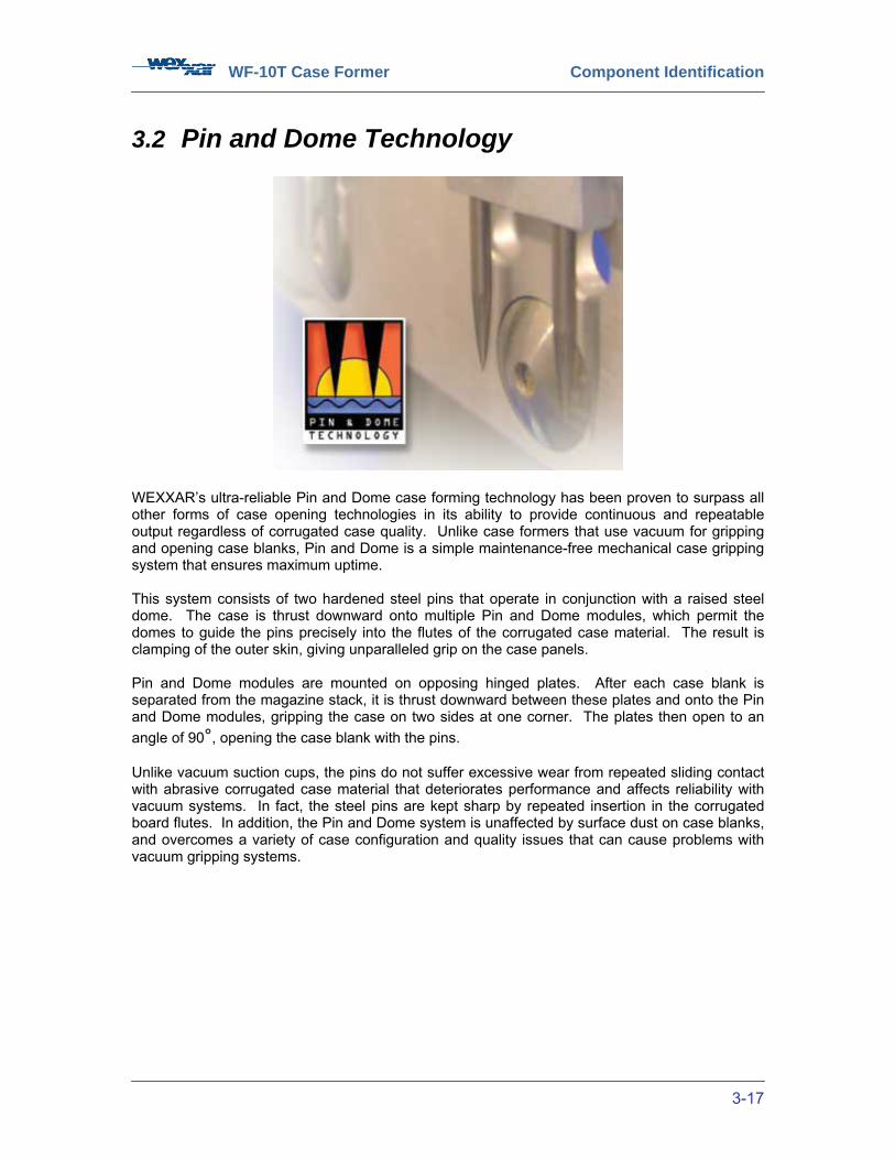
3.2 Pin and Dome Technology
WEXXAR’s ultra-reliable Pin and Dome case forming technology has been proven to surpass all other forms of case opening technologies in its ability to provide continuous and repeatable output regardless of corrugated case quality. Unlike case formers that use vacuum for gripping and opening case blanks, Pin and Dome is a simple maintenance-free mechanical case gripping system that ensures maximum uptime. This system consists of two hardened steel pins that operate in conjunction with a raised steel dome. The case is thrust downward onto multiple Pin and Dome modules, which permit the domes to guide the pins precisely into the flutes of the corrugated case material. The result is clamping of the outer skin, giving unparalleled grip on the case panels. Pin and Dome modules are mounted on opposing hinged plates. After each case blank is separated from the magazine stack, it is thrust downward between these plates and onto the Pin and Dome modules, gripping the case on two sides at one corner. The plates then open to an angle of 90°, opening the case blank with the pins. Unlike vacuum suction cups, the pins do not suffer excessive wear from repeated sliding contact with abrasive corrugated case material that deteriorates performance and affects reliability with vacuum systems. In fact, the steel pins are kept sharp by repeated insertion in the corrugated board flutes. In addition, the Pin and Dome system is unaffected by surface dust on case blanks, and overcomes a variety of case configuration and quality issues that can cause problems with vacuum gripping systems.
WF-10T Case Former Theory of Operation
4-18
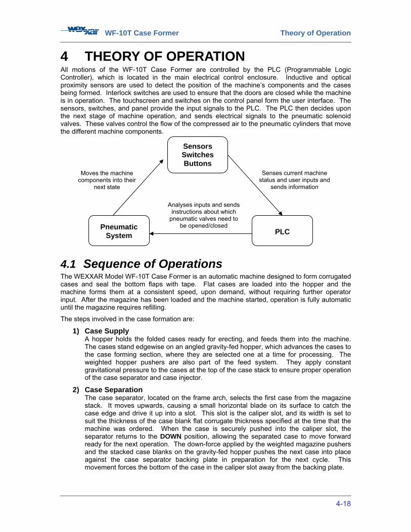
4 THEORY OF OPERATION All motions of the WF-10T Case Former are controlled by the PLC (Programmable Logic Controller), which is located in the main electrical control enclosure. Inductive and optical proximity sensors are used to detect the position of the machine’s components and the cases being formed. Interlock switches are used to ensure that the doors are closed while the machine is in operation. The touchscreen and switches on the control panel form the user interface. The sensors, switches, and panel provide the input signals to the PLC. The PLC then decides upon the next stage of machine operation, and sends electrical signals to the pneumatic solenoid valves. These valves control the flow of the compressed air to the pneumatic cylinders that move the different machine components.
4.1 Sequence of Operations The WEXXAR Model WF-10T Case Former is an automatic machine designed to form corrugated cases and seal the bottom flaps with tape. Flat cases are loaded into the hopper and the machine forms them at a consistent speed, upon demand, without requiring further operator input. After the magazine has been loaded and the machine started, operation is fully automatic until the magazine requires refilling.
The steps involved in the case formation are:
1) Case Supply A hopper holds the folded cases ready for erecting, and feeds them into the machine. The cases stand edgewise on an angled gravity-fed hopper, which advances the cases to the case forming section, where they are selected one at a time for processing. The weighted hopper pushers are also part of the feed system. They apply constant gravitational pressure to the cases at the top of the case stack to ensure proper operation of the case separator and case injector.
2) Case Separation The case separator, located on the frame arch, selects the first case from the magazine stack. It moves upwards, causing a small horizontal blade on its surface to catch the case edge and drive it up into a slot. This slot is the caliper slot, and its width is set to suit the thickness of the case blank flat corrugate thickness specified at the time that the machine was ordered. When the case is securely pushed into the caliper slot, the separator returns to the DOWN position, allowing the separated case to move forward ready for the next operation. The down-force applied by the weighted magazine pushers and the stacked case blanks on the gravity-fed hopper pushes the next case into place against the case separator backing plate in preparation for the next cycle. This movement forces the bottom of the case in the caliper slot away from the backing plate.
Sensors Switches Buttons
Pneumatic System
PLC
Analyses inputs and sends instructions about which
pneumatic valves need to be opened/closed
Senses current machine status and user inputs and
sends information
Moves the machine components into their
next state
WF-10T Case Former Theory of Operation
4-19
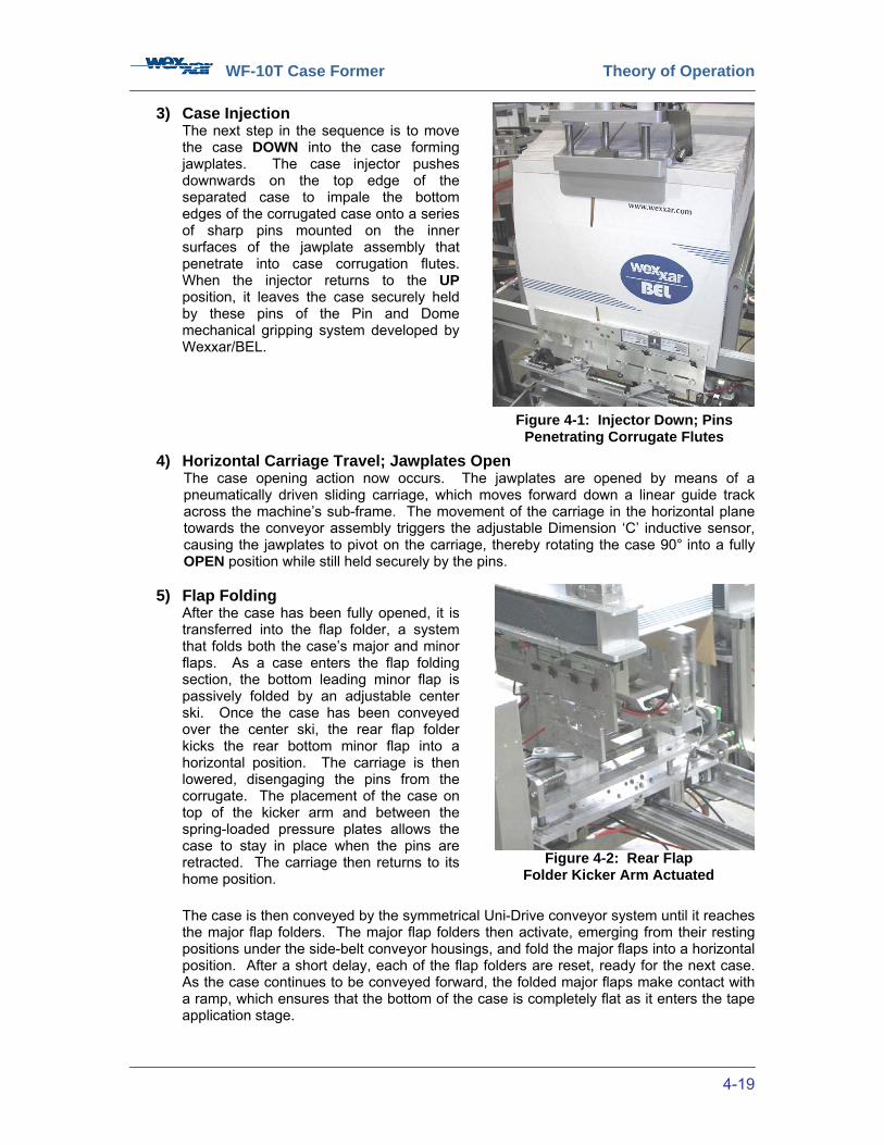
3) Case Injection The next step in the sequence is to move the case DOWN into the case forming jawplates. The case injector pushes downwards on the top edge of the separated case to impale the bottom edges of the corrugated case onto a series of sharp pins mounted on the inner surfaces of the jawplate assembly that penetrate into case corrugation flutes. When the injector returns to the UP position, it leaves the case securely held by these pins of the Pin and Dome mechanical gripping system developed by Wexxar/BEL.
4) Horizontal Carriage Travel; Jawplates Open The case opening action now occurs. The jawplates are opened by means of a pneumatically driven sliding carriage, which moves forward down a linear guide track across the machine’s sub-frame. The movement of the carriage in the horizontal plane towards the conveyor assembly triggers the adjustable Dimension ‘C’ inductive sensor, causing the jawplates to pivot on the carriage, thereby rotating the case 90° into a fully OPEN position while still held securely by the pins.
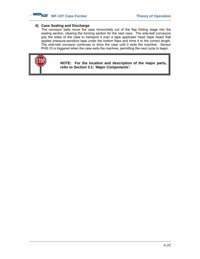
5) Flap Folding After the case has been fully opened, it is transferred into the flap folder, a system that folds both the case’s major and minor flaps. As a case enters the flap folding section, the bottom leading minor flap is passively folded by an adjustable center ski. Once the case has been conveyed over the center ski, the rear flap folder kicks the rear bottom minor flap into a horizontal position. The carriage is then lowered, disengaging the pins from the corrugate. The placement of the case on top of the kicker arm and between the spring-loaded pressure plates allows the case to stay in place when the pins are retracted. The carriage then returns to its home position. The case is then conveyed by the symmetrical Uni-Drive conveyor system until it reaches the major flap folders. The major flap folders then activate, emerging from their resting positions under the side-belt conveyor housings, and fold the major flaps into a horizontal position. After a short delay, each of the flap folders are reset, ready for the next case. As the case continues to be conveyed forward, the folded major flaps make contact with a ramp, which ensures that the bottom of the case is completely flat as it enters the tape application stage.
Figure 4-1: Injector Down; Pins Penetrating Corrugate Flutes
Figure 4-2: Rear Flap Folder Kicker Arm Actuated
WF-10T Case Former Theory of Operation
4-20
6) Case Sealing and Discharge The conveyor belts move the case horizontally out of the flap folding stage into the sealing section, clearing the forming section for the next case. The side-belt conveyors grip the sides of the case to transport it over a tape applicator head (tape head) that applies pressure-sensitive tape under the bottom flaps and trims it to the correct length. The side-belt conveyor continues to drive the case until it exits the machine. Sensor PHS-15 is triggered when the case exits the machine, permitting the next cycle to begin.
NOTE: For the location and description of the major parts, refer to Section 3.1: ‘Major Components’.
WF-10T Case Former Theory of Operation
4-21
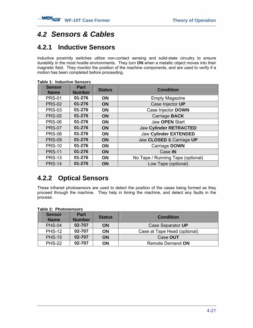
4.2 Sensors & Cables 4.2.1 Inductive Sensors Inductive proximity switches utilize non-contact sensing and solid-state circuitry to ensure durability in the most hostile environments. They turn ON when a metallic object moves into their magnetic field. They monitor the position of the machine components, and are used to verify if a motion has been completed before proceeding. Table 1: Inductive Sensors
Sensor Name
Part Number Status Condition
PRS-01 01-276 ON Empty Magazine PRS-02 01-276 ON Case Injector UP PRS-03 01-276 ON Case Injector DOWN PRS-05 01-276 ON Carriage BACK PRS-06 01-276 ON Jaw OPEN Start PRS-07 01-276 ON Jaw Cylinder RETRACTED PRS-08 01-276 ON Jaw Cylinder EXTENDED PRS-09 01-276 ON Jaw CLOSED & Carriage UP PRS-10 01-276 ON Carriage DOWN PRS-11 01-276 ON Case IN PRS-13 01-276 ON No Tape / Running Tape (optional) PRS-14 01-276 ON Low Tape (optional)
4.2.2 Optical Sensors
These infrared photosensors are used to detect the position of the cases being formed as they proceed through the machine. They help in timing the machine, and detect any faults in the process.
Table 2: Photosensors Sensor Name
Part Number Status Condition
PHS-04 02-707 ON Case Separator UP PHS-12 02-707 ON Case at Tape Head (optional) PHS-15 02-707 ON Case OUT PHS-22 02-707 ON Remote Demand ON
WF-10T Case Former Theory of Operation
4-22
4.2.3 Interlock Switches Interlock switches are used to ensure that all doors are CLOSED while the machine is operating.
Table 3: Interlock Switches
4.2.4 Sensor Cables This machine is equipped with cables of varying lengths, as tabulated below. Refer to the part numbers for ordering replacement parts. Table 4: Sensor Cables
4.3 Pneumatic Valve Bank
Electro-pneumatic solenoid valves provide control of pneumatic operations through the use of machine function feedback. The pneumatic valve bank controls the movements of the machine by converting electrical signals from the PLC into airflow to the pneumatic cylinders that control machine movements.
Each machine movement is able to be performed immediately once the previous pneumatic function has been completed.
All of the solenoid valves are located on the pneumatic valve bank. The valve bank is located on the operator’s side of the machine on the main frame.
WARNING!
As the solenoid assembly de-energizes, either as part of the machine control sequence or in the case of an electrical failure, the possibility of unwanted actuator movement must be considered, so use caution when performing maintenance.
Sensor Name Status Condition DS-1 OPEN LH Side Guard Door OPEN DS-2 OPEN RH Side Guard Door OPEN
Cable Length Part Number Quantity Required 3 Meters 01-259 4 5 Meters 01-275 7
10 Meters 01-260 1
Figure 4-3: Solenoid Valve Bank

WF-10T Case Former Controls
5-23
5 CONTROLS 5.1 Controls Overview The control system consists of a touchscreen interface and a Programmable Logic Controller (PLC), which interact with each other and make the machine operate. The machine controls manage all machine operations. The screen interface located on the main controls enclosure door provides operator control of the machine through software ‘pushbuttons’ displayed on the screen. It also provides instructions on machine operation. This section lists the standard controls on a WF-10T. Actual control functions may vary depending on options installed on your machine. Pay special attention to the location of the three ‘EMERGENCY STOP’ buttons, the ‘RESET’ button, and the main electrical and pneumatic disconnect switches.
5.2 Controls Description 1) ‘ON – OFF’ Disconnect Switch
The disconnect switch turns the main electrical power to the machine ON or OFF; it can be locked in the OFF position for safety during maintenance operations. 2) ‘RESET’ Button
The blue ‘RESET’ button returns the machine to a state in which it is ready to resume operation after an emergency stop or other machine fault. 3) ‘EMERGENCY STOP’ Buttons
Touching any of the three ‘EMERGENCY STOP’ buttons immediately cuts off electrical and air supply to the machine, and halts all operations regardless of whether a case is positioned in the forming process when the button is pushed IN. Power is removed from the main air valve and all mechanisms. Restarting the machine after an emergency stop is more complex. Most likely, the case that was being formed will be wasted. Refer to Section 6.4: ‘Clearing a Case Jam’.
After consulting Section 6.4, the ‘EMERGENCY STOP’ button should be released (raised) and the ‘RESET’ button pushed for the machine to operate again.
Figure 5-1: Main Disconnect Switch
Figure 5-2: ‘RESET’ Button
Figure 5-3: ‘EMERGENCY STOP’ Buttons

WF-10T Case Former Controls
5-24
Figure 5-4: 'Service' Screen
4) Touchscreen Display
The following control descriptions refer to the software ‘buttons’ or ‘switches’ which appear on the display screen, and which act as though they were hardware equivalents. Touching the ‘Service’ screen anywhere will activate the ‘Main Control’ screen. Normal machine status messages are shown green in the ‘Main Control’ screen in the ‘Machine Alarm’ display. Machine fault messages are shown in this display in red. They identify serious problems with the machine. Amber remedy messages and cautionary messages of impending faults are scrolled in the ‘Warning Message’ display immediately below the machine status messages.
Figure 5-5: 'Main Control' Screen
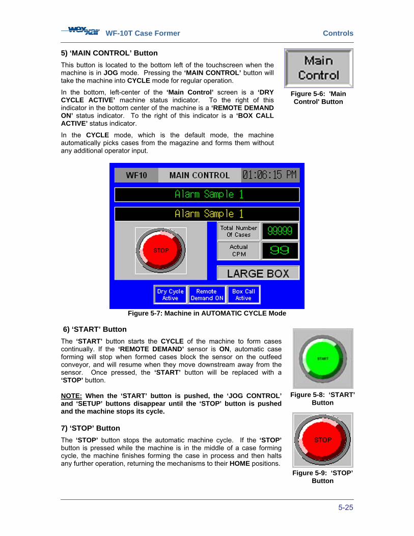
WF-10T Case Former Controls
5-25
5) ‘MAIN CONTROL’ Button
This button is located to the bottom left of the touchscreen when the machine is in JOG mode. Pressing the ‘MAIN CONTROL’ button will take the machine into CYCLE mode for regular operation.
In the bottom, left-center of the ‘Main Control’ screen is a ‘DRY CYCLE ACTIVE’ machine status indicator. To the right of this indicator in the bottom center of the machine is a ‘REMOTE DEMAND ON’ status indicator. To the right of this indicator is a ‘BOX CALL ACTIVE’ status indicator.
In the CYCLE mode, which is the default mode, the machine automatically picks cases from the magazine and forms them without any additional operator input.
Figure 5-7: Machine in AUTOMATIC CYCLE Mode
6) ‘START’ Button
The ‘START’ button starts the CYCLE of the machine to form cases continually. If the ‘REMOTE DEMAND’ sensor is ON, automatic case forming will stop when formed cases block the sensor on the outfeed conveyor, and will resume when they move downstream away from the sensor. Once pressed, the ‘START’ button will be replaced with a ‘STOP’ button. NOTE: When the ‘START’ button is pushed, the ‘JOG CONTROL’ and ‘SETUP’ buttons disappear until the ‘STOP’ button is pushed and the machine stops its cycle. 7) ‘STOP’ Button
The ‘STOP’ button stops the automatic machine cycle. If the ‘STOP’ button is pressed while the machine is in the middle of a case forming cycle, the machine finishes forming the case in process and then halts any further operation, returning the mechanisms to their HOME positions.
Figure 5-6: 'Main Control' Button
Figure 5-8: ‘START’ Button
Figure 5-9: ‘STOP’ Button
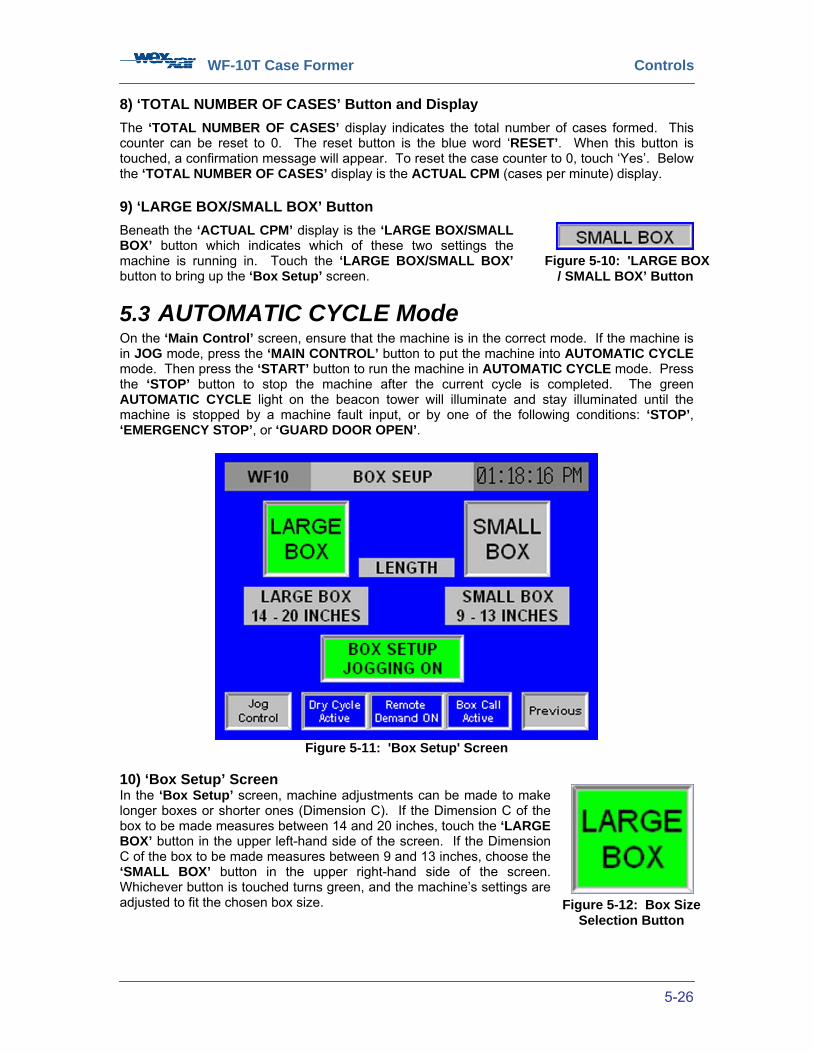
WF-10T Case Former Controls
5-26
8) ‘TOTAL NUMBER OF CASES’ Button and Display
The ‘TOTAL NUMBER OF CASES’ display indicates the total number of cases formed. This counter can be reset to 0. The reset button is the blue word ‘RESET’. When this button is touched, a confirmation message will appear. To reset the case counter to 0, touch ‘Yes’. Below the ‘TOTAL NUMBER OF CASES’ display is the ACTUAL CPM (cases per minute) display. 9) ‘LARGE BOX/SMALL BOX’ Button
Beneath the ‘ACTUAL CPM’ display is the ‘LARGE BOX/SMALL BOX’ button which indicates which of these two settings the machine is running in. Touch the ‘LARGE BOX/SMALL BOX’ button to bring up the ‘Box Setup’ screen.
5.3 AUTOMATIC CYCLE Mode On the ‘Main Control’ screen, ensure that the machine is in the correct mode. If the machine is in JOG mode, press the ‘MAIN CONTROL’ button to put the machine into AUTOMATIC CYCLE mode. Then press the ‘START’ button to run the machine in AUTOMATIC CYCLE mode. Press the ‘STOP’ button to stop the machine after the current cycle is completed. The green AUTOMATIC CYCLE light on the beacon tower will illuminate and stay illuminated until the machine is stopped by a machine fault input, or by one of the following conditions: ‘STOP’, ‘EMERGENCY STOP’, or ‘GUARD DOOR OPEN’.
Figure 5-11: 'Box Setup' Screen
10) ‘Box Setup’ Screen In the ‘Box Setup’ screen, machine adjustments can be made to make longer boxes or shorter ones (Dimension C). If the Dimension C of the box to be made measures between 14 and 20 inches, touch the ‘LARGE BOX’ button in the upper left-hand side of the screen. If the Dimension C of the box to be made measures between 9 and 13 inches, choose the ‘SMALL BOX’ button in the upper right-hand side of the screen. Whichever button is touched turns green, and the machine’s settings are adjusted to fit the chosen box size.
Figure 5-10: 'LARGE BOX / SMALL BOX’ Button
Figure 5-12: Box Size Selection Button
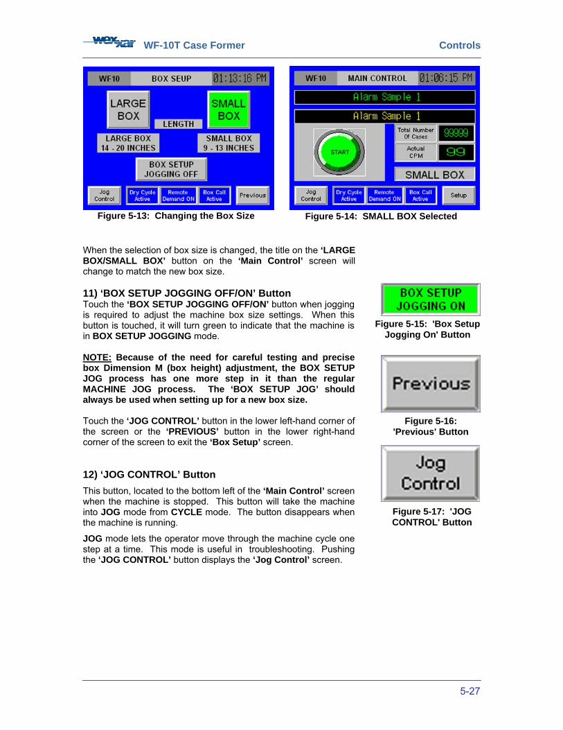
WF-10T Case Former Controls
5-27
When the selection of box size is changed, the title on the ‘LARGE BOX/SMALL BOX’ button on the ‘Main Control’ screen will change to match the new box size. 11) ‘BOX SETUP JOGGING OFF/ON’ Button Touch the ‘BOX SETUP JOGGING OFF/ON’ button when jogging is required to adjust the machine box size settings. When this button is touched, it will turn green to indicate that the machine is in BOX SETUP JOGGING mode. NOTE: Because of the need for careful testing and precise box Dimension M (box height) adjustment, the BOX SETUP JOG process has one more step in it than the regular MACHINE JOG process. The ‘BOX SETUP JOG’ should always be used when setting up for a new box size. Touch the ‘JOG CONTROL’ button in the lower left-hand corner of the screen or the ‘PREVIOUS’ button in the lower right-hand corner of the screen to exit the ‘Box Setup’ screen. 12) ‘JOG CONTROL’ Button
This button, located to the bottom left of the ‘Main Control’ screen when the machine is stopped. This button will take the machine into JOG mode from CYCLE mode. The button disappears when the machine is running.
JOG mode lets the operator move through the machine cycle one step at a time. This mode is useful in troubleshooting. Pushing the ‘JOG CONTROL’ button displays the ‘Jog Control’ screen.
Figure 5-13: Changing the Box Size Figure 5-14: SMALL BOX Selected
Figure 5-15: 'Box Setup Jogging On' Button
Figure 5-16: 'Previous' Button
Figure 5-17: 'JOG CONTROL' Button

WF-10T Case Former Controls
5-28
5.4 JOG Mode This feature is useful for training purposes or for troubleshooting. See Section 9.3: ‘Machine Sequence Troubleshooting’. Touch the ‘JOG CONTROL’ button on the ‘Main Control’ screen to enter into JOG mode. Touching the ‘JOG CONTROL’ button displays the ‘Jog Control’ screen. Touch the ‘START’ button in JOG mode to cycle the machine through its operational sequence, one step for each push of the button.
14) ‘Jog Control’ Screen
Along the bottom of the screen, sensor status indicators show which sensors are activated during each step. As the machine is jogged through its steps, each sensor indicator, in turn, flashes repeatedly until that machine step is complete, at which time the sensor is continuously illuminated until the machine is jogged to the next step. For troubleshooting instructions, please refer to Section 10: ‘Troubleshooting & Repairs’. 15) ‘MACHINE CYCLE JOG’ Button
In the center of the ‘Jog Control’ screen is the ‘MACHINE CYCLE JOG’ button. Each time it is pressed, the machine moves through a single step of the box-forming process. At the top of the screen, the display shows what the next step will be when the ‘MACHINE CYCLE JOG’ pushbutton is pushed again. 16) ‘SETUP’ Button
To change any of the machine control settings for purposes such as activating or deactivating the BOX CALL operation, the ‘REMOTE DEMAND’ sensor or DRY CYCLE operation for the purpose of troubleshooting, press the ‘SETUP’ button in the bottom right-hand corner of either the ‘Jog Control’ or ‘Main Control’ screens. The ‘SETUP’ button disappears from the ‘Main Control’ screen when the machine is running in CYCLE mode.
Figure 5-18: ‘Jog Control’ Screen
Figure 5-19: JOG CONTROL Status Indicator Illuminated
Figure 5-20: Sensor Status Indicator
Figure 5-21: 'MACHINE CYCLE JOG' Button
Figure 5-22: 'SETUP' Button
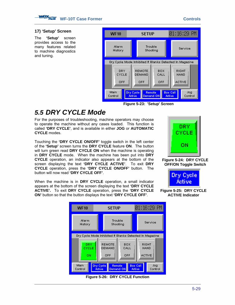
WF-10T Case Former Controls
5-29
Figure 5-23: 'Setup' Screen
5.5 DRY CYCLE Mode For the purposes of troubleshooting, machine operators may choose to operate the machine without any cases loaded. This function is called ‘DRY CYCLE’, and is available in either JOG or AUTOMATIC CYCLE modes. Touching the ‘DRY CYCLE ON/OFF’ toggle switch in the left center of the ‘Setup’ screen turns the DRY CYCLE feature ON. The button will turn green read DRY CYCLE ON when the machine is operating in DRY CYCLE mode. When the machine has been put into DRY CYCLE operation, an indicator also appears at the bottom of the screen displaying the text ‘DRY CYCLE ACTIVE’. To exit DRY CYCLE operation, press the ‘DRY CYCLE ON/OFF’ button. The button will now read ‘DRY CYCLE OFF’. When the machine is in DRY CYCLE operation, a small indicator appears at the bottom of the screen displaying the text ‘DRY CYCLE ACTIVE’. To exit DRY CYCLE operation, press the ‘DRY CYCLE ON’ button so that the button displays the text ‘DRY CYCLE OFF’.
Figure 5-26: DRY CYCLE Function
17) ‘Setup’ Screen
The ‘Setup’ screen provides access to the many features related to machine diagnostics and tuning.
Figure 5-24: DRY CYCLE OFF/ON Toggle Switch
Figure 5-25: DRY CYCLE ACTIVE Indicator

WF-10T Case Former Controls
5-30
18) REMOTE DEMAND Operation
Located in the center of the ‘Setup’ screen, this toggle switch turns the REMOTE DEMAND operation ON or OFF.
REMOTE DEMAND is used to halt machine operation if cases are not moving away from the machine on the downstream conveyor, thus avoiding jams. In this way, it also matches case-forming output to the rate of consumption by downstream processes. To enable the REMOTE DEMAND function, touch the ‘REMOTE DEMAND OFF/ON’ toggle switch, which will then turn green and display the text ‘REMOTE DEMAND ON’. Also, the remote demand sensor should be placed facing a suitable location on the discharge conveyor belt. In that way, if finished boxes are accumulating on the conveyor belt, the remote demand sensor can stop the machine from producing more boxes. When the remote demand has been turned ON, a small indicator appears at the bottom of the screen displaying the text ‘REMOTE DEMAND ON’.
.
Figure 5-27: 'REMOTE DEMAND OFF/ON’
Toggle Switch
Figure 5-28: REMOTE DEMAND Indicator
Figure 5-29: REMOTE DEMAND Function Figure 5-30: Remote Demand Sensor
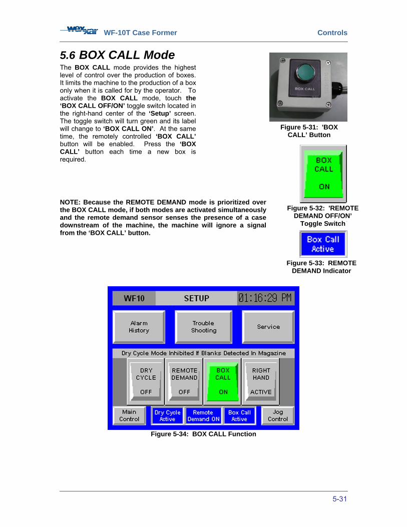
WF-10T Case Former Controls
5-31
5.6 BOX CALL Mode The BOX CALL mode provides the highest level of control over the production of boxes. It limits the machine to the production of a box only when it is called for by the operator. To activate the BOX CALL mode, touch the ‘BOX CALL OFF/ON’ toggle switch located in the right-hand center of the ‘Setup’ screen. The toggle switch will turn green and its label will change to ‘BOX CALL ON’. At the same time, the remotely controlled ‘BOX CALL’ button will be enabled. Press the ‘BOX CALL’ button each time a new box is required. NOTE: Because the REMOTE DEMAND mode is prioritized over the BOX CALL mode, if both modes are activated simultaneously and the remote demand sensor senses the presence of a case downstream of the machine, the machine will ignore a signal from the ‘BOX CALL’ button.
Figure 5-34: BOX CALL Function
Figure 5-31: 'BOX CALL’ Button
.
Figure 5-32: 'REMOTE DEMAND OFF/ON’
Toggle Switch
Figure 5-33: REMOTE DEMAND Indicator

WF-10T Case Former Controls
5-32
5.7 Case Orientation Changes Corrugated case blanks have an orientation (or ‘handing’), depending on what is sometimes called the case printing direction. The handing is determined by the orientation of printing on the longest sides of the case in relation to the relative position of the smaller end panels. There are two possibilities that are mirror images of each other, and the relationship determines the direction in which the case is opened. The illustration below shows the difference in relative position of printing on the major side panel in relation to minor end panels and the Wexxar definition of matching right-hand and left-hand case erecting machine construction.
In hand erecting of cases, the printing direction is not usually an issue, as the individual who is forming the case will compensate for the difference by keeping the bottom of the case ‘down’ and the print upright and readable. However, automatic case forming requires that the case be erected from the case blank in a consistent left-to-right or right-to-left direction as determined by the way the cases were printed when they were made. If the erecting order does not match the printing direction, the only way the cases can be erected on an automatic former is with the printing, and therefore the formed case, upside down. Needless to say, case printing direction orientation has been a source of considerable confusion in matching forming machines to the case blanks that they are intended to erect, and a common problem in the industry has been the arrival of case samples to test on a completed machine being of the opposite hand to which the machine was built. Contract packing houses have usually had to have separate machines of each orientation in order to handle the variation in customer cases. The WF-10T case former is not only unique in its use of mechanical case gripping through Pin & Dome technology to form the case from the bottom, it uses this technology to erect either right-hand or left-hand cases through a relatively straightforward machine change-over procedure. The WF-10T manages to handle the different case orientations by gripping the flaps of both opposing side panels at the same time as it erects the case from the case blank. The significance of this method is that erecting a right- or left-handed case is primarily determined by the direction of rotation of the jawplates as the case moves through the machine.
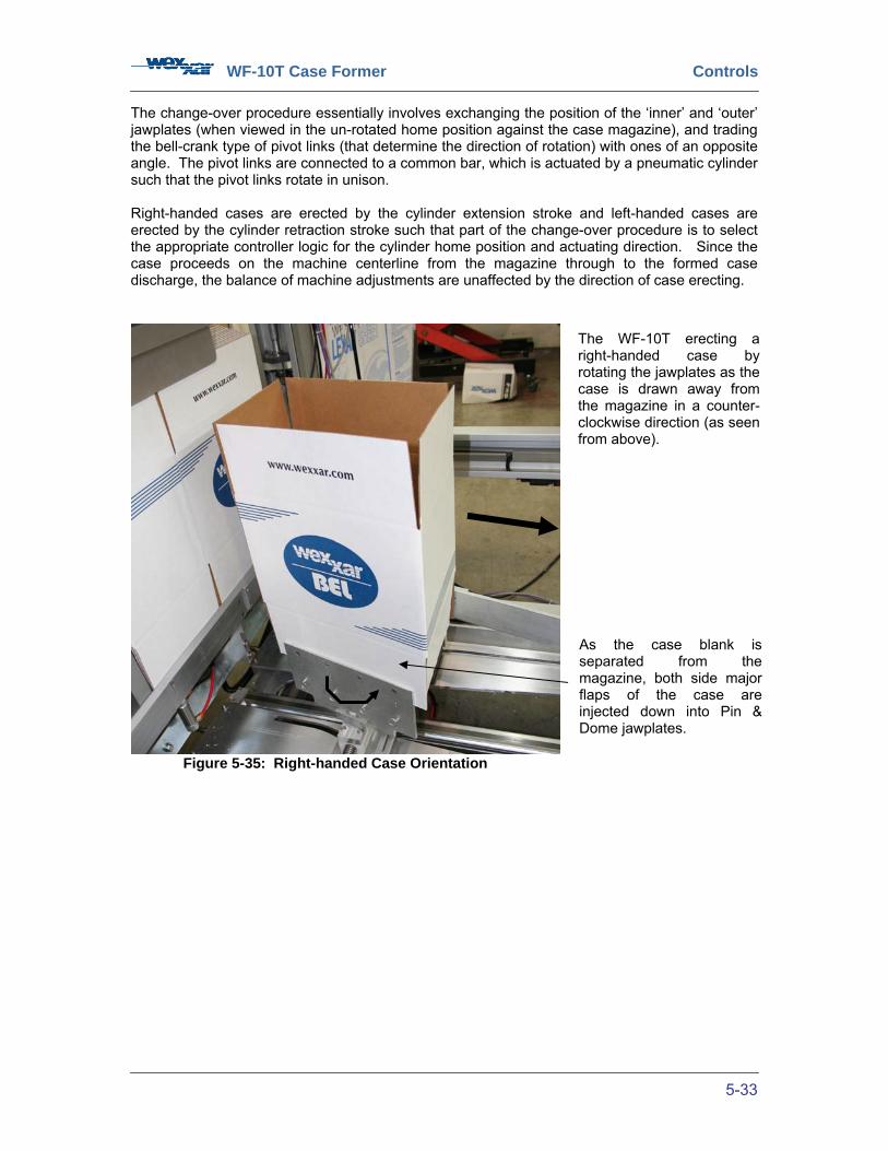
WF-10T Case Former Controls
5-33
The change-over procedure essentially involves exchanging the position of the ‘inner’ and ‘outer’ jawplates (when viewed in the un-rotated home position against the case magazine), and trading the bell-crank type of pivot links (that determine the direction of rotation) with ones of an opposite angle. The pivot links are connected to a common bar, which is actuated by a pneumatic cylinder such that the pivot links rotate in unison. Right-handed cases are erected by the cylinder extension stroke and left-handed cases are erected by the cylinder retraction stroke such that part of the change-over procedure is to select the appropriate controller logic for the cylinder home position and actuating direction. Since the case proceeds on the machine centerline from the magazine through to the formed case discharge, the balance of machine adjustments are unaffected by the direction of case erecting.
Figure 5-35: Right-handed Case Orientation
The WF-10T erecting a right-handed case by rotating the jawplates as the case is drawn away from the magazine in a counter-clockwise direction (as seen from above).
As the case blank is separated from the magazine, both side major flaps of the case are injected down into Pin & Dome jawplates.

WF-10T Case Former Controls
5-34
5.7.1 Case Orientation Change-over Procedure The default case orientation, or ‘handing’, for WF-10T case formers is configured with right-handed cases. Machine operators requiring left-handed case orientation can change the machine’s case orientation by following the instructions below. For someone familiar with the process, performing a case size change-over should take approximately half an hour. See the following page for diagram of pertinent parts. 1) In the ‘SETUP’ screen, toggle the ‘CASE ORIENTATION’
toggle switch ON or OFF. In the machine’s default orientation, the switch will be ON (illuminated green) and display the text ‘LEFT HAND ACTIVE’. The toggle switch will turn gray and display the text ‘RIGHT HAND ACTIVE’ only when the machine operator has pressed the switch. Note that handing changes require the machine operator to enter a password, which will have been provided at the time of purchase.
2) Follow the shutdown procedure outlined in Section 6.5:
‘Shutdown’. If required, lock out pneumatic and electrical disconnects as required by local regulations.
3) Open a guard door and enter the machine’s restrictive envelope. Locate the carriage
assembly. Using a 5/32” Allen key, remove the jawplate mounting screws that secure the jawplates to the jaw mount plates. Detach jawplates from machine.
4) Remove the pivot link mounting screws that secure the pivot links to the carriage
assembly. Detach pivot links from machine and replace with provided replacement pivot links for right-hand jawplate orientation. Secure replacement pivot links with provided screws.
5) Remove the 4 screws that secure the major jawplate to the major jawplate extension
mount and that secure the major jawplate extension to the extension mount. Reorient the jawplate extension and jawplate extension mount on the opposing side, ensuring that the extension mount is mounted towards the discharge end of the machine. Replace screws.
6) Reattach the jawplates to the jaw mount plates using the screws provided. Ensure that
you reverse the position of the jawplates so that they are mounted opposite to the original configuration. The major jawplate should be mounted towards the discharge end of the machine.
7) Detach Magazine Plate 7 (Item # 22 on drawing 610-0002) from the Magazine Taper
Plate and reattach it on the opposite side of the centerline in the bolt holes provided. 8) It may be necessary to recalibrate the jawplate cylinder flow controls when conducting a
handing change-over. Call Wexxar Service Department for more detailed information. 9) Close the guard door and restart the machine according to the procedure outlined in
Section 6.2: ‘Start-up’. The case orientation changeover is now complete.
.
Figure 5-36: 'Case Orientation’ Toggle
Switch
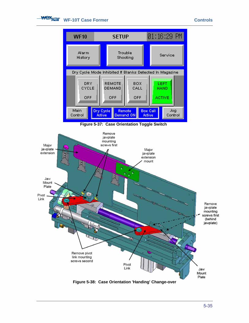
WF-10T Case Former Controls
5-35
Figure 5-38: Case Orientation 'Handing' Change-over
Figure 5-37: Case Orientation Toggle Switch
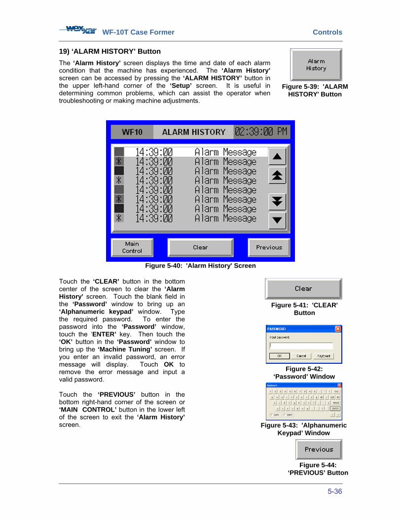
WF-10T Case Former Controls
5-36
19) ‘ALARM HISTORY’ Button
The ‘Alarm History’ screen displays the time and date of each alarm condition that the machine has experienced. The ‘Alarm History’ screen can be accessed by pressing the ‘ALARM HISTORY’ button in the upper left-hand corner of the ‘Setup’ screen. It is useful in determining common problems, which can assist the operator when troubleshooting or making machine adjustments.
Figure 5-40: 'Alarm History' Screen
Touch the ‘CLEAR’ button in the bottom center of the screen to clear the ‘Alarm History’ screen. Touch the blank field in the ‘Password’ window to bring up an ‘Alphanumeric keypad’ window. Type the required password. To enter the password into the ‘Password’ window, touch the ‘ENTER’ key. Then touch the ‘OK’ button in the ‘Password’ window to bring up the ‘Machine Tuning’ screen. If you enter an invalid password, an error message will display. Touch OK to remove the error message and input a valid password. Touch the ‘PREVIOUS’ button in the bottom right-hand corner of the screen or ‘MAIN CONTROL’ button in the lower left of the screen to exit the ‘Alarm History’ screen.
Figure 5-39: 'ALARM HISTORY' Button
Figure 5-41: 'CLEAR' Button
Figure 5-42: ‘Password’ Window
Figure 5-43: 'Alphanumeric Keypad’ Window
Figure 5-44: ‘PREVIOUS’ Button
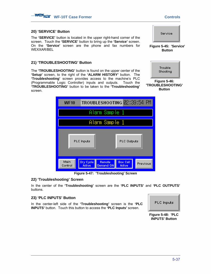
WF-10T Case Former Controls
5-37
20) ‘SERVICE’ Button
The ‘SERVICE’ button is located in the upper right-hand corner of the screen. Touch the ‘SERVICE’ button to bring up the ‘Service’ screen. On the ‘Service’ screen are the phone and fax numbers for WEXXAR/BEL 21) ‘TROUBLESHOOTING’ Button The ‘TROUBLESHOOTING’ button is found on the upper center of the ‘Setup’ screen, to the right of the ‘ALARM HISTORY’ button. The ‘Troubleshooting’ screen provides access to the machine’s PLC (Programmable Logic Controller) inputs and outputs. Touch the ‘TROUBLESHOOTING’ button to be taken to the ‘Troubleshooting’ screen.
Figure 5-47: 'Troubleshooting' Screen
22) ‘Troubleshooting’ Screen
In the center of the ‘Troubleshooting’ screen are the ‘PLC INPUTS’ and ‘PLC OUTPUTS’ buttons. 23) ‘PLC INPUTS’ Button
In the center-left side of the ‘Troubleshooting’ screen is the ‘PLC INPUTS’ button. Touch this button to access the ‘PLC Inputs’ screen.
Figure 5-45: 'Service' Button
Figure 5-46: 'TROUBLESHOOTING’
Button
Figure 5-48: 'PLC INPUTS’ Button
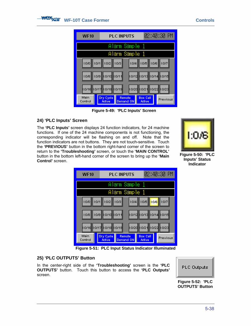
WF-10T Case Former Controls
5-38
24) ‘PLC Inputs’ Screen
The ‘PLC Inputs’ screen displays 24 function indicators, for 24 machine functions. If one of the 24 machine components is not functioning, the corresponding indicator will be flashing on and off. Note that the function indicators are not buttons. They are not touch-sensitive. Touch the ‘PREVIOUS’ button in the bottom right-hand corner of the screen to return to the ‘Troubleshooting’ screen, or touch the ‘MAIN CONTROL’ button in the bottom left-hand corner of the screen to bring up the ‘Main Control’ screen.
Figure 5-51: PLC Input Status Indicator Illuminated
25) ‘PLC OUTPUTS’ Button
In the center-right side of the ‘Troubleshooting’ screen is the ‘PLC OUTPUTS’ button. Touch this button to access the ‘PLC Outputs’ screen.
Figure 5-49: 'PLC Inputs’ Screen
Figure 5-50: 'PLC Inputs’ Status
Indicator
Figure 5-52: 'PLC OUTPUTS’ Button

WF-10T Case Former Controls
5-39
Figure 5-53: 'PLC Outputs' Screen
26) ‘PLC Outputs’ Screen The ‘PLC Outputs’ screen displays sixteen buttons. Each of these output buttons controls a PLC output directly. To test these functions, stop the machine and remove any unformed cases from the magazine. Then touch each button. When a button is touched, it will illuminate and that machine component will function. If it does not function, inspect and repair the component. Touch the ‘PREVIOUS’ button in the bottom right-hand corner of the ‘PLC Outputs’ screen to return to the ‘Troubleshooting’ screen. Touch the ‘MAIN CONTROL’ button in the bottom left-hand corner of the screen to bring up the ‘Main Control’ screen.
Figure 5-55: PLC Output Function Indicator Illuminated
Figure 5-54: 'PLC Outputs’ Status
Indicator
WF-10T Case Former Operating Procedures
6-40
6 OPERATING PROCEDURES 6.1 Safety Equipment Safety The WF-10T has safety features to prevent you from injury while the machine is operational. Guard doors, equipped with interlock switches, are in place to prevent you from entering the work cell while the case forming is in progress; the machine will not run if these doors are open. The access door of the electrical enclosure also has to be closed for the machine to operate. The perimeter guarding system surrounds the area known as the restrictive envelope and covers the entire range of possible machine motion. For your safety, you should never try to bypass the perimeter guarding system or enter the restrictive envelope while the machine is in operation. An ‘EMERGENCY STOP’ button is provided to immediately halt all machine operation by cutting off air supply and electrical power. This button should be pushed IN to stop the machine in case of an emergency.
Precautions • The WF-10T Case Former is equipped with safety interlocks. Do not attempt to disable
or bypass the safety interlocks or any other safety features when operating the machine. • Always follow the specified procedure when operating the machine.

WF-10T Case Former Operating Procedures
6-41
6.2 Start-up 6.2.1 Preliminary Checks
Before placing the WEXXAR Model WF-10T Case Former into operation, check the following points:
• Is the machine set correctly for the case size? Scales showing the required settings are located on the machine, and provide an easy quick check. If adjustments are required, please refer to Section 7: ‘Case Size Adjustments’ of this manual.
• Is the magazine properly loaded with cases.
• Is sufficient air pressure available? Check that the gauge reads 90 PSI on the regulator.
The manual shutoff valve must be OPEN.
• Are all guards properly closed, and all personnel clear?
• Is the electrical power disconnect switch turned ON? The Black operating lever should be in a vertical position. Are the ‘EMERGENCY STOP’ buttons in the OUT position? Turn clockwise or pull out to release.
• Is the tape applicator on the WF-10T properly installed, loaded with a tape roll, and ready
to go? The end of the tape should be on the front roller, with the sticky side facing the incoming case. For complete tape installation instructions, see the separate Dekka Tape Head Manual that is supplied with this machine. If your machine came with a non-standard tape head, refer to the appropriate tape head manual.
• Does the touchscreen display the desired mode of operation? The normal mode of
operation allows AUTOMATIC CYCLE operation. The special JOG mode is intended for operator training or troubleshooting.
WARNING!
Note that when the machine is first switched on, the jawplates and carriage will cycle once automatically. Keep hands out of the machine when starting.
WF-10T Case Former Operating Procedures
6-42
Check the ‘S’ box for Satisfactory Performance and ‘US’ box for Unsatisfactory Performance.
Table 5: Preliminary Start-up Checklist Machine Start-up Preliminary checks S US
Check if the machine is set up for the right case size.
Check if the machine is properly loaded.
Check if the air pressure is set correctly to 90 PSI, with the manual shutoff valve open.
Verify that all guard doors are closed and that all personnel are clear.
Verify that the electrical power disconnect switch is turned ON and that the ‘EMERGENCY STOP’ button in the OUT position.
Check if the tape applicator is properly installed, loaded with a tape roll, and ready to go.
6.2.2 Start-up Procedures After completing the procedures outlined in Section 6.2.1: ‘Preliminary Checks’, start the machine as follows:
1) Press the ‘RESET’ button once. Air pressure will now be applied to the various machine mechanism cylinders. The remaining mechanisms move to their respective HOME positions as follows:
Table 6: Mechanism HOME Positions and Valve Numbers Mechanism HOME Position Valve Number
Case Separator Valve DOWN V1 Injector Valve UP V2
Carriage Back Valve V3A Carriage Forward Valve Carriage BACK V3B
Jaws Cylinder Retracted Valve V4A Jaws Cylinder Extended Valve CLOSED V4B
Carriage Up/Down Valve DOWN V5 Minor Folder Raise/Lower Valve DOWN V6
Major Folder On/Off Valve OFF V7 Conveyor Motor OFF N/A
2) Check that the conveyor side-belts are tracking properly. They should be centered on the drive pulley, properly tensioned, and in reasonably good condition.

WF-10T Case Former Operating Procedures
6-43
Check the ‘S’ box for Satisfactory Performance and ‘US’ box for Unsatisfactory Performance. Table 7: Machine Start-up Procedures Machine Start-up Start-up Procedures S US
Select the procedure for the desired mode of operation below:
AUTOMATIC CYCLE Operation:
Press the ‘RESET’ button.
If machine is not in AUTOMATIC CYCLE mode, press the ‘MAIN CONTROL’ button.
Press the ‘START’ button to begin cycling cases.
JOG Operation:
Press the ‘RESET’ button.
If machine is not in JOG mode, press the ‘JOG MODE’ button.
Press the START button once for each stage in the case forming and sealing process.
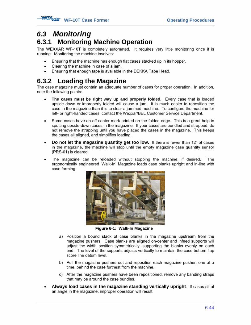
WF-10T Case Former Operating Procedures
6-44
6.3 Monitoring 6.3.1 Monitoring Machine Operation The WEXXAR WF-10T is completely automated. It requires very little monitoring once it is running. Monitoring the machine involves:
• Ensuring that the machine has enough flat cases stacked up in its hopper. • Clearing the machine in case of a jam. • Ensuring that enough tape is available in the DEKKA Tape Head.
6.3.2 Loading the Magazine The case magazine must contain an adequate number of cases for proper operation. In addition, note the following points:
• The cases must be right way up and properly folded. Every case that is loaded upside down or improperly folded will cause a jam. It is much easier to reposition the case in the magazine than it is to clear a jammed machine. To configure the machine for left- or right-handed cases, contact the Wexxar/BEL Customer Service Department.
• Some cases have an off-center mark printed on the folded edge. This is a great help in spotting upside-down cases in the magazine. If your cases are bundled and strapped, do not remove the strapping until you have placed the cases in the magazine. This keeps the cases all aligned, and simplifies loading.
• Do not let the magazine quantity get too low. If there is fewer than 12" of cases in the magazine, the machine will stop until the empty magazine case quantity sensor (PRS-01) is cleared.
• The magazine can be reloaded without stopping the machine, if desired. The ergonomically engineered ‘Walk-In’ Magazine loads case blanks upright and in-line with case forming.
a) Position a bound stack of case blanks in the magazine upstream from the magazine pushers. Case blanks are aligned on-center and infeed supports will adjust the width position symmetrically, supporting the blanks evenly on each end. The level of the supports adjusts vertically to maintain the case bottom flap score line datum level.
b) Pull the magazine pushers out and reposition each magazine pusher, one at a time, behind the case furthest from the machine.
c) After the magazine pushers have been repositioned, remove any banding straps that may be around the case bundles.
• Always load cases in the magazine standing vertically upright. If cases sit at an angle in the magazine, improper operation will result.
Figure 6-1: Walk-In Magazine
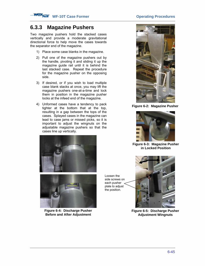
WF-10T Case Former Operating Procedures
6-45
6.3.3 Magazine Pushers Two magazine pushers hold the stacked cases vertically and provide a moderate gravitational directional force to help move the cases towards the separator end of the magazine.
1) Place some case blanks in the magazine.
2) Pull one of the magazine pushers out by the handle, pivoting it and sliding it up the magazine guide rail until it is behind the last stacked case. Repeat the procedure for the magazine pusher on the opposing side.
3) If desired, or if you wish to load multiple case blank stacks at once, you may lift the magazine pushers one-at-a-time and lock them in position in the magazine pusher locks at the infeed end of the magazine.
4) Unformed cases have a tendency to pack tighter at the bottom that at the top, resulting in a gap between the tops of the cases. Splayed cases in the magazine can lead to case jams or missed picks, so it is important to adjust the wingnuts on the adjustable magazine pushers so that the cases line up vertically.
Figure 6-2: Magazine Pusher
Figure 6-3: Magazine Pusher in Locked Position
Figure 6-4: Discharge Pusher Before and After Adjustment
Figure 6-5: Discharge Pusher Adjustment Wingnuts
Loosen the side screws on each pusher plate to adjust the position.
WF-10T Case Former Operating Procedures
6-46
Check the ‘S’ box for Satisfactory Performance and ‘US’ box for Unsatisfactory Performance.
Table 8: Machine Loading Checklist
Loading the Machine S US
Position fresh cases in the magazine behind the magazine pushers.
One at a time, lift each of the two magazine pushers up to clear the stacked cases, pull them back, and reposition them to push on the last case. If desired, lock the magazine pushers in place while loading the magazine.
Remove any banding straps that may be around the case bundles.
WF-10T Case Former Operating Procedures
6-47
6.4 Clearing a Case Jam The WEXXAR Model WF-10T Case Formers will provide reliable, trouble-free performance on a wide variety of case sizes. Occasional jams are not uncommon, but frequent jamming can usually be traced to a particular reason, such as incorrectly set machine adjustment, and corrected. Refer to Section 7: ‘Case Size Adjustments’, Section 8.5: ‘Maintenance Adjustments’ and Section 9: ‘Troubleshooting & Repairs’ for further information.
To place the machine back into service as quickly as possible after a jam has occurred, proceed as follows:
1. Press one of the ‘EMERGENCY STOP’ buttons. This will shut off the electrical and air power to the machine mechanisms. It may take a few moments for the system air pressure to decline to zero; wait approximately 3 seconds, or until air pressure has fully exhausted and all mechanisms are stationary before proceeding.
2. If required by local regulations or company policy, lock out the electrical power and air supply before proceeding.
3. Open the guard door for access to the jammed case. 4. Remove all jammed case corrugate. Any mechanism that is entangled with the jammed
case may safely be moved by hand, as all air pressure has been exhausted.
5. Close the guard door and pull out the ‘EMERGENCY STOP’ button. Remove lock-out, if applicable.
6. Press the ‘RESET’ button and restart the machine by following the start-up procedure in Section 6.2: ‘Start-up’.
7. After clearing all mechanisms to their HOME positions when the machine is restarted. Refer to Section 6.2.2: ‘Start-up Procedures’.
Check the ‘S’ box for Satisfactory Performance and ‘US’ box for Unsatisfactory Performance. Table 9: Clearing Jams
Clearing Jams S US
Press the ‘EMERGENCY STOP’ button. Wait until air pressure has fully exhausted and all mechanisms are stationary before proceeding.
Open the guard door for access to the jammed case.
Remove all jammed case corrugate by hand.
Close the guard door.
Reset the ‘EMERGENCY STOP’ button.
Press the ‘RESET’ button.
Restart the machine.

WF-10T Case Former Operating Procedures
6-48
6.5 Shutdown
There are several options to stop the machine:
1. ‘STOP’ Button: Pushing the ‘STOP’ button is the proper way to stop the machine in a non-emergency situation. When the ‘STOP’ button is pressed in AUTOMATIC CYCLE mode operation, the case in process is completed, and the mechanisms return to their HOME positions.
2. ‘EMERGENCY STOP’ Button: Pushing the ‘EMERGENCY STOP’ button stops the machine rapidly regardless of where the machine is in its operating cycle. Air and electrical power are removed from the machine mechanisms. Restarting the machine after an emergency stop is more complex. Most likely the case that was being formed will be wasted and have to be removed manually. Refer to Section 6.4: ‘Clearing a Case Jam’.
3. Open a Guard Door: Opening a guard door will stop the machine rapidly regardless of where the machine is in its operating cycle, similar to actuating the ‘EMERGENCY STOP’ button.
4. Disconnect Switch: Turning OFF the disconnect switch or any other means of removing the electrical power will cause the machine to stop rapidly, similar to actuating the ‘EMERGENCY STOP’ button.
5. Turning OFF Pneumatic/Air Supply: Cutting off the compressed air supply to the machine will cause it to halt operation, although the machine will still be electrically powered.
Check the ‘S’ box for Satisfactory Performance and ‘US’ box for Unsatisfactory Performance. Table 10: Machine Shutdown
Shutdown S US
Stop the machine using the following techniques:
Press the ‘STOP’ button.
Press the ‘EMERGENCY STOP’ button.
Open a guard door.
Turn OFF the disconnect switch.
Disconnect the electrical power from the machine (optional).
NOTE: Normal stopping of the machine should be accomplished by using the ‘STOP’ button.

WF-10T Case Former Case Size Adjustments
7-49
7 CASE SIZE ADJUSTMENTS 7.1 Safety Equipment Safety The WF-10T has safety features to prevent you from injury while case size adjustments are being performed. Guard doors, equipped with interlock switches, are in place to prevent you from entering the work cell while the case forming is in progress; the machine will not run if these doors are open. The access door of the electrical enclosure also has to be closed for the machine to operate. The perimeter guarding system surrounds the area known as the restrictive envelope and covers the entire range of possible machine motion. For your safety, you should never try to bypass the perimeter guarding system or enter the restrictive envelope while the machine is in operation. An ‘EMERGENCY STOP’ button is provided to immediately halt all machine operation by cutting off air supply and electrical power. This button should be pushed IN to stop the machine in case of an emergency.
Precautions • Always follow the applicable specified procedure when making case size adjustments.
• The WF-10T Case Former is equipped with safety interlocks. Do not attempt to disable
or bypass the safety interlocks or any other safety features while case size adjustments are being performed.
Applicable Laws • Before making any adjustments to this machine, disconnect the power and lock out
according to local regulations.
WF-10T Case Former Case Size Adjustments
7-50
7.2 Machine Adjustments
The WF-10T has seven machine adjustments that are required when switching between case sizes. The case size adjustment sequence described in the following pages and as shown on the machine itself is ordered so that the adjustments occur in a logical order. For instance, Dimension ‘M’ must be calibrated before Dimension ‘B’, as Dimension ‘B’ is dependent on the lateral datum established by the Dimension ‘M’ calibration. Depending on the orientation of the machine at the time of order, most machine adjustments can be made from the operator’s side of the machine. Some adjustments can be configured on the opposite side of the machine. If you wish to alter the location of any of the machine adjustments, please contact Wexxar/BEL for a technical bulletin outlining the reconfiguration processes. The adjustable machine adjustments are, in order of adjustment:
1) Unlock vertical adjustment chain locks 2) Dimension ‘A’: Case Blank Length 3) Dimension ‘M’: Bottom Flap Height 4) Dimension ‘B’: Case Blank Height 5) Lock vertical adjustment locks 6) Dimension ‘D1’: Jawplate Formed Case Width 7) Horizontal Pinblock Adjustments 8) Pinblock Mounting Orientation 9) Dimension ‘D2’: Center Ski Formed Case Width 10) Dimension ‘D3’: Conveyor Formed Case Width 11) Dimension ‘C’: Carriage Formed Case Length
Begin by measuring the key dimensions of the case. Write the exact measurements down for future reference. Measure Dimensions ‘B’, ‘C’, ‘D’, and ‘M’ against the scale located on the conveyor assembly top plate. Measuring Dimension ‘A’ is optional, as the magazine width can be adjusted to a sliding fit without measuring the case blank width. Write the values down for future reference. When measuring Dimension ‘M’, be sure to measure the height of the smaller of the two flaps. Likewise, when measuring Dimension ‘D’, measure the formed case width at the leading and trailing ends of the case. Note any differences. Measure a second case to validate the measurements taken from the first case. If there is a measured difference between the leading and trailing end of the case, make sure that the jawplate formed case width Dimension ‘D1’ pointer is calibrated to the wider of the two measurements, while the narrower of the two measurements is applied to the conveyor formed case width Dimension ‘D3’ adjustment. Even if the measured formed case widths at the leading and trailing ends of the case are identical, it is still recommended that you set the jawplates slightly wider apart than the conveyors. This will ensure that the jawplate pins that engage the bottom major flaps positions the them slightly wider apart than the trailing bottom flap as it is folded up by the rear kicker arm, allowing it to fold up without any impedance from the bottom major flaps. Note that this machine uses relative proportional scaling. Relative proportional scaling permits proportional adjustments to be harmonized and standardized relative to each other, simplifying case size adjustment procedures. It may be necessary to fine-tune the adjustments sequentially while in JOG mode after initial adjustments have been made.

WF-10T Case Former Case Size Adjustments
7-51
7.3 Case Size Adjustment Instruction Labels For detailed machine adjustment instructions, refer to the case size adjustment instruction labels on the interior of the side guard doors and the jawplate adjustment instruction label on the jawplate assembly.
Figure 7-1: Case Size Adjustment and Jawplate Adjustment Instruction Labels

WF-10T Case Former Case Size Adjustments
7-52
7.4 Case Dimension Measurements Before setting any of the machine adjustments, measure all case dimensions on the scale provided on the conveyor assembly on the operator’s side of the machine. Refer to the images below.
Figure 7-2: Case Dimension Measurements

WF-10T Case Former Case Size Adjustments
7-53
7.5 Case Size Range The following table and diagram show the maximum and minimum case sizes that can be run using the standard WF-10T configuration. Please call your factory representative for more details. Note that the following dimensions are outside dimensions. Table 11: Case Size Range
A M B D1 / D2 / D3 C Case Size
Range MIN MAX MIN MAX MIN MAX MIN MAX MIN MAX
Inches 13 30 4 7.5 5 15 6 15 9 22
Mm 330 762 102 191 127 381 153 381 229 559
Figure 7-3: Case Size Range Dimensional Diagram
Dimension ‘A’
Dim
ension ‘B’
Dim
ension‘M
’
Dimension ‘C’ Dimension ‘D’
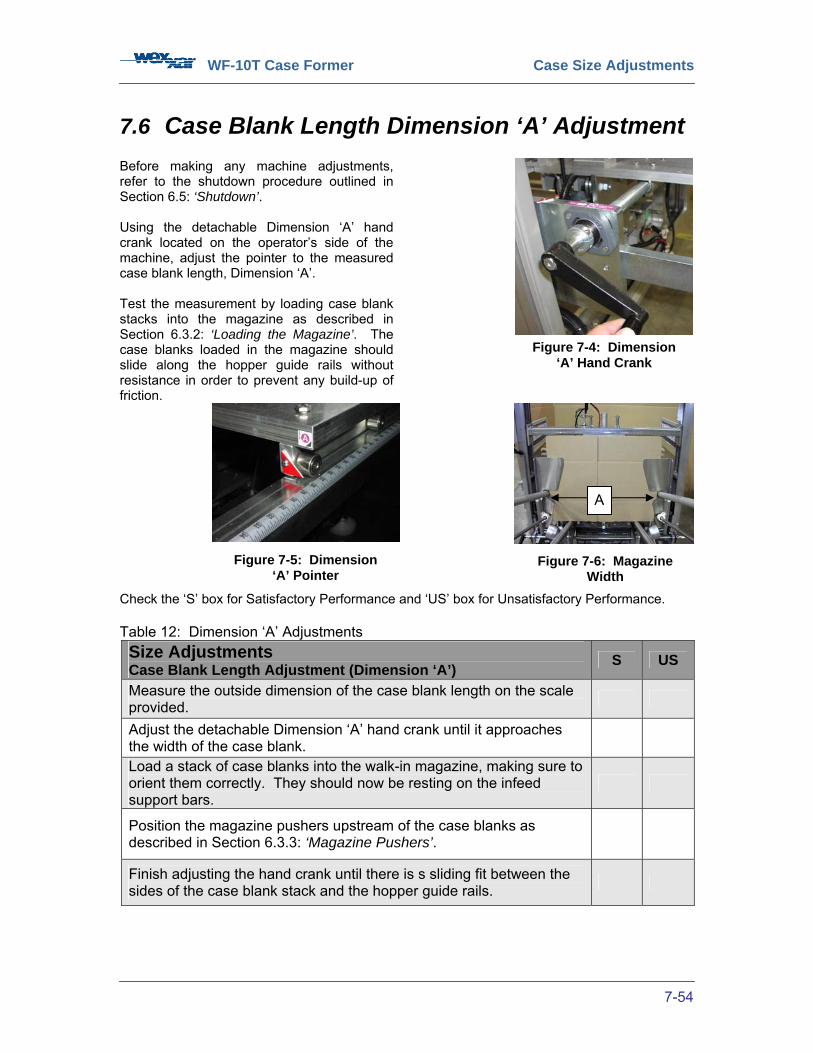
WF-10T Case Former Case Size Adjustments
7-54
7.6 Case Blank Length Dimension ‘A’ Adjustment Before making any machine adjustments, refer to the shutdown procedure outlined in Section 6.5: ‘Shutdown’. Using the detachable Dimension ‘A’ hand crank located on the operator’s side of the machine, adjust the pointer to the measured case blank length, Dimension ‘A’. Test the measurement by loading case blank stacks into the magazine as described in Section 6.3.2: ‘Loading the Magazine’. The case blanks loaded in the magazine should slide along the hopper guide rails without resistance in order to prevent any build-up of friction.
Check the ‘S’ box for Satisfactory Performance and ‘US’ box for Unsatisfactory Performance. Table 12: Dimension ‘A’ Adjustments Size Adjustments Case Blank Length Adjustment (Dimension ‘A’) S US
Measure the outside dimension of the case blank length on the scale provided.
Adjust the detachable Dimension ‘A’ hand crank until it approaches the width of the case blank.
Load a stack of case blanks into the walk-in magazine, making sure to orient them correctly. They should now be resting on the infeed support bars.
Position the magazine pushers upstream of the case blanks as described in Section 6.3.3: ‘Magazine Pushers’.
Finish adjusting the hand crank until there is s sliding fit between the sides of the case blank stack and the hopper guide rails.
Figure 7-4: Dimension ‘A’ Hand Crank
Figure 7-5: Dimension ‘A’ Pointer
Figure 7-6: Magazine Width
A

WF-10T Case Former Case Size Adjustments
7-55
7.7 Bottom Flap Height Dimension ‘M’ Adjustment
Before making any machine adjustments, refer to the shutdown procedure outlined in Section 6.5: ‘Shutdown’. Bottom flat height Dimension ‘M’ provides a baseline datum for adjusting Dimension ‘B’, so it is important to adjust Dimension ‘M’ first. To start with, ensure that you unlock the vertical adjustment lock lever located on the frame arch beaneath the magazine. Then adjust the bottom flap height Dimension ‘M’ hand crank until the ‘M’ pointer on the inverted vertical calibration scale on the machine arch matches the measured bottom flap height. Note that the chain lock may be on the opposite side to what is shown. Note that the Dimension ‘B’ hand crank may have to be adjusted alternately with the Dimension ‘M’ hand crank in order to prevent the case blanks from falling through into the machine’s restrictive envelope. The injector plate should act as a backplate. Ensure that the tops of the stacked case blanks do not make contact with the sensor mounted below the injector. The ‘M’ adjustment is intended to adjust the vertical position of the case blank in the magazine so that the score or fold line for the bottom flaps is level with the bottom of machine conveyor side belts. The bottom flap fold line is thus the ‘datum’ for the vertical position of the case as it moves through the forming, folding and bottom sealing of the cases. If Dimension ‘M’ is correctly adjusted, the bottom score-line on the cases will align horizontally with the top of the ramp where the center ski is mounted. Check the ‘S’ box for Satisfactory Performance and ‘US’ box for Unsatisfactory Performance.
Table 13: Dimension ‘M’ Adjustments
Lower Chain Lock
Figure 7-7: Vertical Adjustment Chain Lock
Figure 7-8:
Dimension ‘M’ Hand Crank
Figure 7-9: Dimension ‘M’
Pointer
Size Adjustments Bottom Flap Height Adjustment (Dimension ‘M’) S US
Unlock the Dimension ‘M’ vertical adjustment lock mounted on the frame arch underneath the magazine.
Measure the outside dimension of the bottom minor flap height on the scale provided.
Adjust the Dimension ‘M’ leadscrew using the detachable hand crank provided until the ‘M’ pointer aligns with the measured bottom flap height on the inverted scale.
Re-lock the Dimension ‘M’ vertical adjustment lock.

WF-10T Case Former Case Size Adjustments
7-56
7.8 Case Blank Height Dimension ‘B’ Adjustment Before making any machine adjustments, refer to the shutdown procedure outlined in Section 6.5: ‘Shutdown’. Measure the height of the case blank on the scale provided and turn the Dimension ‘B’ hand crank until the top of the case reaches the ‘B’ pointer labels on the outfeed side of the injector. First, unlock the Dimension ‘B’ vertical adjustment chain lock located on the top of the machine arch. Note that the chain lock may be on the opposite side to what is shown. Then adjust the height of the case injector so that the ‘B’ line mark on the injector is level with the top of the first case blank in the magazine. Ensure that the tops of the stacked case blanks do not make contact with the sensor mounted below the injector. The case blank height adjustment hand crank can be located on either side of the machine arch. For more information, contact your Wexxar/BEL representative. Ensure that you re-lock the vertical adjustment chain lock before continuing.
Check the ‘S’ box for Satisfactory Performance and ‘US’ box for Unsatisfactory Performance. Table 14: Dimension ‘B’ Adjustments Size Adjustments Case Blank Height Adjustment (Dimension ‘B’) S US
Unlock the vertical adjustment chain lock located on the top bar of the frame arch.
Measure the outside dimension of the case blank height on the scale provided.
Adjust the Dimension ‘B’ leadscrew using the detachable hand crank provided until it reaches the ‘B’ pointer labels on the injector.
Ensure that you re-lock the vertical adjustment chain lock before continuing.
Figure 7-10: Dimension ‘B’ Vertical Adjustment Chain Lock
Figure 7-11: Dimension ‘B’ Pointer on Injector Backplate
Figure 7-12: Dimension ‘B’ Hand Crank
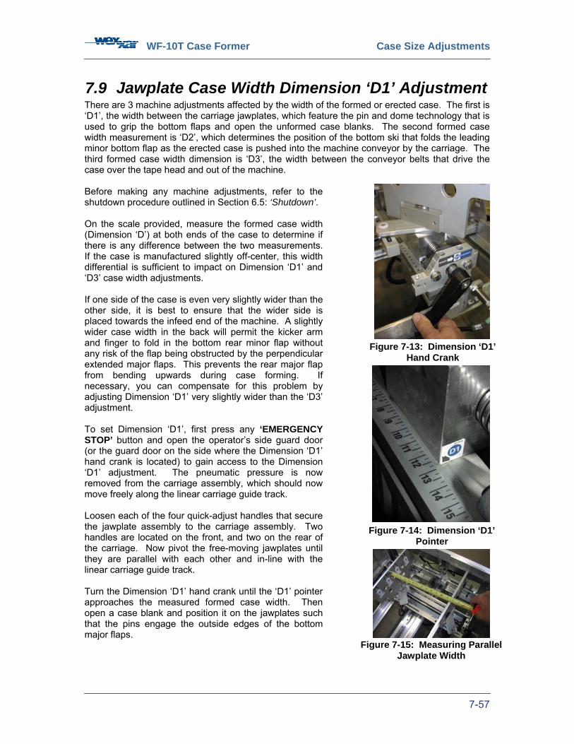
WF-10T Case Former Case Size Adjustments
7-57
7.9 Jawplate Case Width Dimension ‘D1’ Adjustment There are 3 machine adjustments affected by the width of the formed or erected case. The first is ‘D1’, the width between the carriage jawplates, which feature the pin and dome technology that is used to grip the bottom flaps and open the unformed case blanks. The second formed case width measurement is ‘D2’, which determines the position of the bottom ski that folds the leading minor bottom flap as the erected case is pushed into the machine conveyor by the carriage. The third formed case width dimension is ‘D3’, the width between the conveyor belts that drive the case over the tape head and out of the machine. Before making any machine adjustments, refer to the shutdown procedure outlined in Section 6.5: ‘Shutdown’. On the scale provided, measure the formed case width (Dimension ‘D’) at both ends of the case to determine if there is any difference between the two measurements. If the case is manufactured slightly off-center, this width differential is sufficient to impact on Dimension ‘D1’ and ‘D3’ case width adjustments. If one side of the case is even very slightly wider than the other side, it is best to ensure that the wider side is placed towards the infeed end of the machine. A slightly wider case width in the back will permit the kicker arm and finger to fold in the bottom rear minor flap without any risk of the flap being obstructed by the perpendicular extended major flaps. This prevents the rear major flap from bending upwards during case forming. If necessary, you can compensate for this problem by adjusting Dimension ‘D1’ very slightly wider than the ‘D3’ adjustment. To set Dimension ‘D1’, first press any ‘EMERGENCY STOP’ button and open the operator’s side guard door (or the guard door on the side where the Dimension ‘D1’ hand crank is located) to gain access to the Dimension ‘D1’ adjustment. The pneumatic pressure is now removed from the carriage assembly, which should now move freely along the linear carriage guide track. Loosen each of the four quick-adjust handles that secure the jawplate assembly to the carriage assembly. Two handles are located on the front, and two on the rear of the carriage. Now pivot the free-moving jawplates until they are parallel with each other and in-line with the linear carriage guide track. Turn the Dimension ‘D1’ hand crank until the ‘D1’ pointer approaches the measured formed case width. Then open a case blank and position it on the jawplates such that the pins engage the outside edges of the bottom major flaps.
Figure 7-13: Dimension ‘D1’ Hand Crank
Figure 7-14: Dimension ‘D1’ Pointer
Figure 7-15: Measuring Parallel Jawplate Width
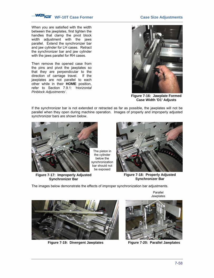
WF-10T Case Former Case Size Adjustments
7-58
When you are satisfied with the width between the jawplates, first tighten the handles that clamp the pivot block width adjustment with the jaws parallel. Extend the synchronizer bar and jaw cylinder for LH cases. Retract the synchronizer bar and jaw cylinder with the jaws parallel for RH cases. Then remove the opened case from the pins and pivot the jawplates so that they are perpendicular to the direction of carriage travel. If the jawplates are not parallel to each other while in their HOME position, refer to Section 7.9.1: ‘Horizontal Pinblock Adjustments’. If the synchronizer bar is not extended or retracted as far as possible, the jawplates will not be parallel when they open during machine operation. Images of properly and improperly adjusted synchronizer bars are shown below.
The images below demonstrate the effects of improper synchronization bar adjustments.
Figure 7-16: Jawplate Formed Case Width 'D1' Adjusts
Figure 7-17: Improperly Adjusted Synchronizer Bar
Figure 7-18: Properly Adjusted Synchronizer Bar
Figure 7-19: Divergent Jawplates Figure 7-20: Parallel Jawplates
The piston in the cylinder below the
synchronization bar should not
be exposed
Parallel Jawplates

WF-10T Case Former Case Size Adjustments
7-59
Check the ‘S’ box for Satisfactory Performance and ‘US’ box for Unsatisfactory Performance. Table 15: Dimension ‘D1’ Adjustments Size Adjustments Jawplate Formed Case Width Adjustment (Dimension ‘D1’) S US
Measure the outside dimension of the formed case width on the scale provided.
Press any ‘EMERGENCY STOP’ button and open the operator’s side guard door.
Loosen the four quick-adjust handles (2 in front and 2 in the rear) that secure the jawplate assembly to the carriage assembly.
Pivot the free-moving jawplates until they are in-line with the linear carriage guide track.
Turn the Dimension ‘D1’ hand crank until the ‘D1’ pointer reaches the measured formed case width.
Place an opened case blank on the jawplates such that the pins engage the outside edges of the bottom major flaps.
Retighten the four quick-adjust handles.
Remove the opened case from the pins and pivot the jawplates so that they are perpendicular to the direction of carriage travel.
Ensure that jawplates are aligned parallel to each other.
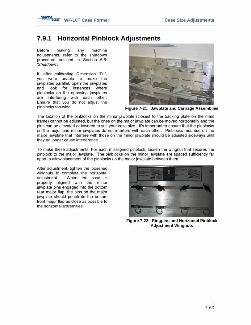
WF-10T Case Former Case Size Adjustments
7-60
7.9.1 Horizontal Pinblock Adjustments Before making any machine adjustments, refer to the shutdown procedure outlined in Section 6.5: ‘Shutdown’. If, after calibrating Dimension ‘D1’, you were unable to make the jawplates parallel, open the jawplates and look for instances where pinblocks on the opposing jawplates are interfering with each other. Ensure that you do not adjust the pinblocks too wide. The location of the pinblocks on the minor jawplate (closest to the backing plate on the main frame) cannot be adjusted, but the ones on the major jawplate can be moved horizontally and the pins can be elevated or lowered to suit your case size. It’s important to ensure that the pinblocks on the major and minor jawplates do not interfere with each other. Pinblocks mounted on the major jawplate that interfere with those on the minor jawplate should be adjusted sideways until they no longer cause interference. To make these adjustments: For each misaligned pinblock, loosen the wingnut that secures the pinblock to the major jawplate. The pinblocks on the minor jawplate are spaced sufficiently far apart to allow placement of the pinblocks on the major jawplate between them. After adjustment, tighten the loosened wingnuts to complete the horizontal adjustment. When the case is properly aligned with the minor jawplate pins engaged into the bottom rear major flap, the pins on the major jawplate should penetrate the bottom front major flap as close as possible to the horizontal extremities.
Figure 7-21: Jawplate and Carriage Assemblies
Figure 7-22: Ringpins and Horizontal Pinblock Adjustment Wingnuts
WF-10T Case Former Case Size Adjustments
7-61
Check the ‘S’ box for Satisfactory Performance and ‘US’ box for Unsatisfactory Performance. Table 16: Horizontal Pinblock Adjustments Size Adjustments Horizontal Pinblock Adjustment S US
Ensure that the pinblocks on the major and minor jawplates do not interfere with each other.
Adjust pinblocks on the major jawplate that interfere with those on the minor jawplate sideways until they no longer cause interference.
For each misaligned pinblock, loosen the wingnut that secures the pinblock to the major jawplate.
Tighten the loosened wingnuts to complete the horizontal adjustment.
To change the depth of penetration of the pins in the corrugate flutes, pull out the selected pin ring on the out-facing side of the major jawplate. Position pins in pinblocks to the optimal height for the selected case size.
Ensure that there is under ½” of exposed pin at the bottom of the case corrugate.
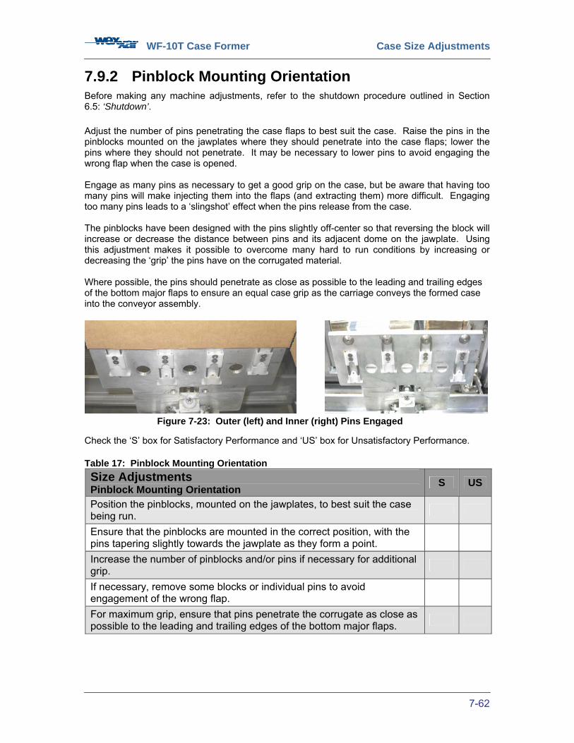
WF-10T Case Former Case Size Adjustments
7-62
7.9.2 Pinblock Mounting Orientation Before making any machine adjustments, refer to the shutdown procedure outlined in Section 6.5: ‘Shutdown’. Adjust the number of pins penetrating the case flaps to best suit the case. Raise the pins in the pinblocks mounted on the jawplates where they should penetrate into the case flaps; lower the pins where they should not penetrate. It may be necessary to lower pins to avoid engaging the wrong flap when the case is opened. Engage as many pins as necessary to get a good grip on the case, but be aware that having too many pins will make injecting them into the flaps (and extracting them) more difficult. Engaging too many pins leads to a ‘slingshot’ effect when the pins release from the case. The pinblocks have been designed with the pins slightly off-center so that reversing the block will increase or decrease the distance between pins and its adjacent dome on the jawplate. Using this adjustment makes it possible to overcome many hard to run conditions by increasing or decreasing the ‘grip’ the pins have on the corrugated material. Where possible, the pins should penetrate as close as possible to the leading and trailing edges of the bottom major flaps to ensure an equal case grip as the carriage conveys the formed case into the conveyor assembly.
Check the ‘S’ box for Satisfactory Performance and ‘US’ box for Unsatisfactory Performance. Table 17: Pinblock Mounting Orientation Size Adjustments Pinblock Mounting Orientation S US
Position the pinblocks, mounted on the jawplates, to best suit the case being run.
Ensure that the pinblocks are mounted in the correct position, with the pins tapering slightly towards the jawplate as they form a point.
Increase the number of pinblocks and/or pins if necessary for additional grip.
If necessary, remove some blocks or individual pins to avoid engagement of the wrong flap.
For maximum grip, ensure that pins penetrate the corrugate as close as possible to the leading and trailing edges of the bottom major flaps.
Figure 7-23: Outer (left) and Inner (right) Pins Engaged

WF-10T Case Former Case Size Adjustments
7-63
7.9.3 Bottom Carriage Jawplate Pin & Dome Position Adjustments
The position and extension of the pins that are inserted into the edges of the bottom flaps when the case is injected down onto them and that ‘grip’ the case for opening may need to be adjusted depending on the case size and proportions. The pins are intended to engage the longer major flaps only and must be repositioned, retracted or removed if they will engage the shorter minor flaps or if they will hit pins on the other jawplate when in the closed position. The need to change the pin and dome positions will be most likely with small or narrow-width cases.
Figure 7-24: Pin & Dome Position Adjustments
Pin blocks can be removed, if necessary
Pin blocks must be positioned so they don’t contact blocks on the opposite jawplate and prevent the plates from fully closing.
Pins interfering with case erecting
Retracting pins

WF-10T Case Former Case Size Adjustments
7-64
7.10 Center Ski Case Width Dimension ‘D2’ Adjustment Before making any machine adjustments, refer to the shutdown procedure outlined in Section 6.5: ‘Shutdown’.
The center ski that serves to passively fold down the leading bottom minor flap is mounted on a slotted bracket that permits the ski to be adjusted forward towards, or away from, the machine infeed. It is used to fold the leading minor flap as the case is pushed into the conveyor and flap folding section of the machine. Its position is affected by the width of the case due to the fact that with the most common RSC style case, all the bottom flap heights or widths are ½ the width of the case. The ski must be positioned so that it will not interfere with the folding of the rear minor flap by the active folder. This adjustment is generally less critical than the other case width adjustments and for most mid-size cases it will probably be possible to find a position in the middle of the adjustment range that will suit them all. Its position is more critical with the smallest and largest size cases. When running cases with widths that are close to the machine’s minimum or maximum limits, it may be necessary to adjust the position of the ski to ensure that the minor flaps are folded correctly. To run most case widths that are close to the machine’s average width capabilities, the ski should be set at roughly the midpoint on its mounting slot. For cases that are close to the machine’s maximum width capability, or cases with a larger than normal minor flap height, the ski should be adjusted away from the machine infeed, such that the rear minor flap does not contact the ski before it is fully folded up. For cases that are near the machine’s minimum width capability, or cases with a smaller than normal minor flap height, the ski should be adjusted toward the machine infeed, such that the rear minor flap does not spring open before it reaches the ski and is guided above it. In general, the minimum distance between the bottom of the folded rear flap and the center ski should be 1”. Check the ‘S’ box for Satisfactory Performance and ‘US’ box for Unsatisfactory Performance. Table 18: Dimension ‘D2’ Adjustments Size Adjustments Center Ski Formed Case Width Adjustment (Dimension ‘D2’) S US
Loosen the bottom center ski quick-adjust handle. Reposition the ski along the scale until the ‘D2’ pointer matches the measured formed case width, or until the clearance between the arc of the bottom flap as it’s being folded and the center ski is at least 1”.
Figure 7-25: Clearance Between Rear Flap and Center Ski
Figure 7-26: Bottom Center Ski
Rear Flap Folder Kicker Arm Extension
‘D2’ Adjustment Handle
Direction of Case Travel
Center Ski

WF-10T Case Former Case Size Adjustments
7-65
7.11 Conveyor Case Width Dimension ‘D3’ Adjustment Before making any machine adjustments, refer to the shutdown procedure outlined in Section 6.5: ‘Shutdown’. The most practical way to adjust the conveyor width to the case size is to use a formed case. The conveyor width can be adjusted by using the hand crank to move the side-belt conveyors IN or OUT to fit the width of the case. Adjust the drivebelts in until it is just possible to remove it, then turn the adjustment crank in a further ½ turn, or until the case just slides easily between the infeed guides. There is no locking mechanism for this adjustment. The spring-loaded pressure plates behind the conveyor side-belts in the tape sealing area are more absorptive than any of our other WF Series machines due to the long length of the conveyor belts and the precision control required to prevent the ‘squashing’ of the case sides that make contact with the belts. Check the ‘S’ box for Satisfactory Performance and ‘US’ box for Unsatisfactory Performance. Table 19: Dimension ‘D3’ Adjustments Size Adjustments Conveyor Formed Case Width Adjustment (Dimension ‘D3’) S US
Measure the outside dimension of the formed case width on the scale provided.
Use the side hand crank to move the side-belt conveyors IN or OUT to fit the width of the case.
Use a formed case to verify the measurement.
Figure 7-27: Dimension ‘D3’ Case Width Adjust
Figure 7-28: Case Width Verification

WF-10T Case Former Case Size Adjustments
7-66
7.12 Carriage Case Length Dimension C Adjustment The formed case length adjustment determines how far the carriage needs to push the erected case into the conveyor so that the rear of the case is in the right position for rear minor flap folding. The quick-adjust handle and scales are on the operator’s side of the carriage sub-frame. This adjustment has two scale ranges, one for formed cases up to 12” in length and one for formed cases from 12” to a maximum of 22”. Each has a corresponding pointer on the scale provided. The 3” difference in the ranges is due to the relative position of cases in the conveyor section of the machine and due to different characteristics of small and large cases.
Before making any machine adjustments, refer to the shutdown procedure outlined in Section 6.5: ‘Shutdown’. To adjust the carriage formed case length Dimension ‘C’ measurement, adhere to the following the procedure. Open the operator’s side guard door. Adjust the formed case length Dimension ‘C’ quick-adjust handle to the measured formed case length. Following the procedure outlined in Section 5.3: ‘BOX SETUP JOGGING OFF/ON Button’, put the machine into ‘BOX JOG’ mode. Jog the machine through until the case is conveyed forward by the carriage into the case forming area between the conveyors. Note the position of the rear of the case relative to the rear plates of the conveyor assemblies. For cases shorter than 12” in length, the rear plates (those nearest to the machine arch) should line up with the rear of the case. For cases longer than 12” in length, the rear panel of the case should line up with the trailing end of the conveyor assembly top plates (those nearest to the machine arch). If the case does not line up, press ‘E-STOP’ and open the operator’s side guard door. Remove the case from the jawplates. Adjust the formed case length Dimension ‘C’ quick-adjust handle to the distance on the proportional scale that corresponds to the position of the rear wall of the case relative to the rear plate of the conveyor assemblies. Close the guard door, pull out any ‘E-STOP’ buttons, and press ‘RESET’. Keep jogging cases through the machine until the rear of the case is even with the rear plates.
Figure 7-29: Dimension ‘C’ Formed Case Length Adjust
Figure 7-30: Jawplate and Carriage Assemblies
Small case scale for case lengths up to 12”
Large case scale for case lengths greater than 12”
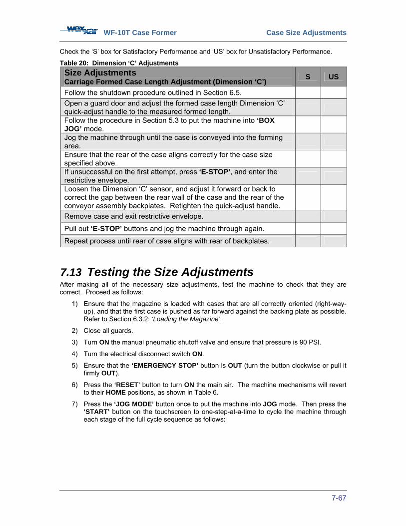
WF-10T Case Former Case Size Adjustments
7-67
Check the ‘S’ box for Satisfactory Performance and ‘US’ box for Unsatisfactory Performance.
Table 20: Dimension ‘C’ Adjustments Size Adjustments Carriage Formed Case Length Adjustment (Dimension ‘C’) S US
Follow the shutdown procedure outlined in Section 6.5. Open a guard door and adjust the formed case length Dimension ‘C’ quick-adjust handle to the measured formed length.
Follow the procedure in Section 5.3 to put the machine into ‘BOX JOG’ mode.
Jog the machine through until the case is conveyed into the forming area.
Ensure that the rear of the case aligns correctly for the case size specified above.
If unsuccessful on the first attempt, press ‘E-STOP’, and enter the restrictive envelope.
Loosen the Dimension ‘C’ sensor, and adjust it forward or back to correct the gap between the rear wall of the case and the rear of the conveyor assembly backplates. Retighten the quick-adjust handle.
Remove case and exit restrictive envelope.
Pull out ‘E-STOP’ buttons and jog the machine through again.
Repeat process until rear of case aligns with rear of backplates.
7.13 Testing the Size Adjustments After making all of the necessary size adjustments, test the machine to check that they are correct. Proceed as follows:
1) Ensure that the magazine is loaded with cases that are all correctly oriented (right-way-up), and that the first case is pushed as far forward against the backing plate as possible. Refer to Section 6.3.2: ‘Loading the Magazine’.
2) Close all guards.
3) Turn ON the manual pneumatic shutoff valve and ensure that pressure is 90 PSI.
4) Turn the electrical disconnect switch ON.
5) Ensure that the ‘EMERGENCY STOP’ button is OUT (turn the button clockwise or pull it firmly OUT).
6) Press the ‘RESET’ button to turn ON the main air. The machine mechanisms will revert to their HOME positions, as shown in Table 6.
7) Press the ‘JOG MODE’ button once to put the machine into JOG mode. Then press the ‘START’ button on the touchscreen to one-step-at-a-time to cycle the machine through each stage of the full cycle sequence as follows:
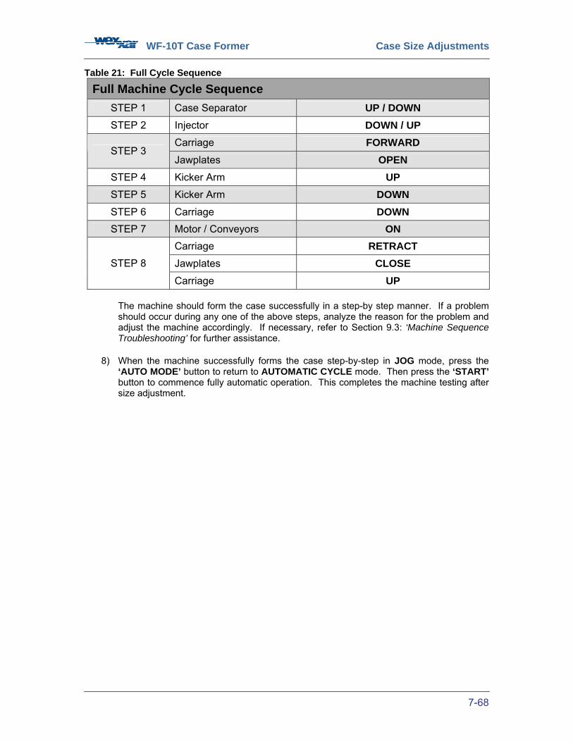
WF-10T Case Former Case Size Adjustments
7-68
Table 21: Full Cycle Sequence
Full Machine Cycle Sequence
STEP 1 Case Separator UP / DOWN STEP 2 Injector DOWN / UP
Carriage FORWARD STEP 3
Jawplates OPEN STEP 4 Kicker Arm UP STEP 5 Kicker Arm DOWN STEP 6 Carriage DOWN STEP 7 Motor / Conveyors ON
Carriage RETRACT Jawplates CLOSE STEP 8
Carriage UP The machine should form the case successfully in a step-by step manner. If a problem should occur during any one of the above steps, analyze the reason for the problem and adjust the machine accordingly. If necessary, refer to Section 9.3: ‘Machine Sequence Troubleshooting’ for further assistance.
8) When the machine successfully forms the case step-by-step in JOG mode, press the ‘AUTO MODE’ button to return to AUTOMATIC CYCLE mode. Then press the ‘START’ button to commence fully automatic operation. This completes the machine testing after size adjustment.
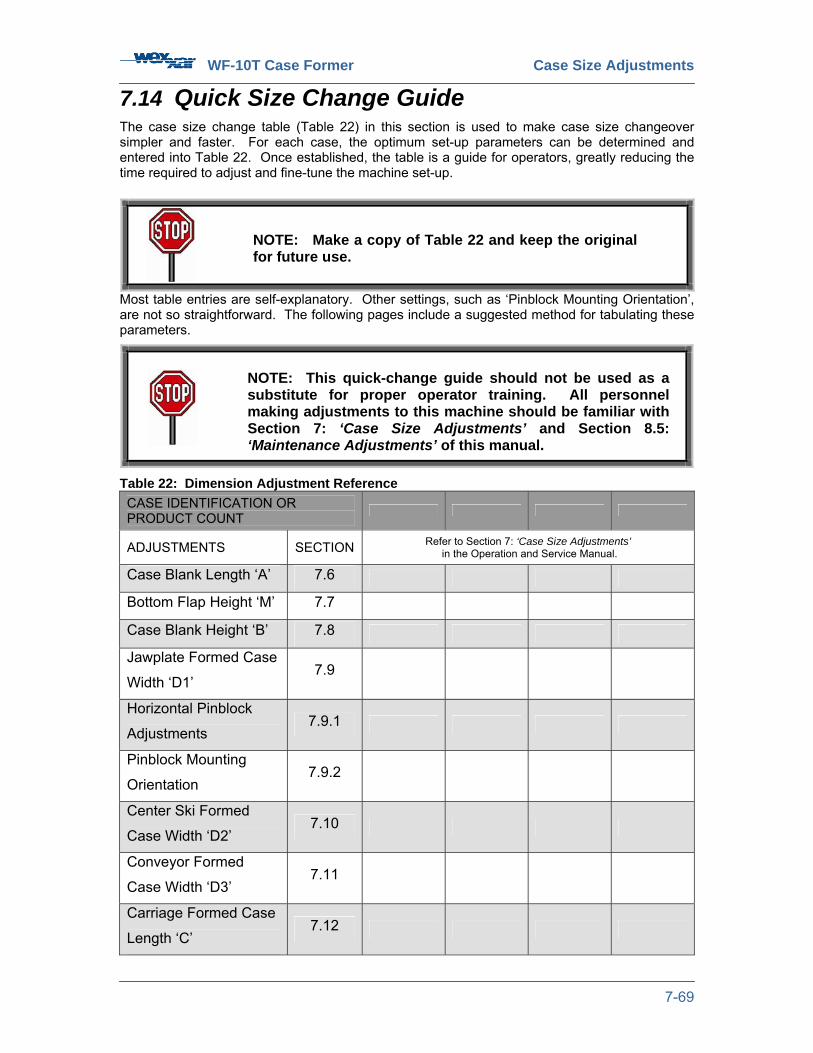
WF-10T Case Former Case Size Adjustments
7-69
7.14 Quick Size Change Guide The case size change table (Table 22) in this section is used to make case size changeover simpler and faster. For each case, the optimum set-up parameters can be determined and entered into Table 22. Once established, the table is a guide for operators, greatly reducing the time required to adjust and fine-tune the machine set-up.
Most table entries are self-explanatory. Other settings, such as ‘Pinblock Mounting Orientation’, are not so straightforward. The following pages include a suggested method for tabulating these parameters.
Table 22: Dimension Adjustment Reference CASE IDENTIFICATION OR PRODUCT COUNT
ADJUSTMENTS SECTION Refer to Section 7: ‘Case Size Adjustments’ in the Operation and Service Manual.
Case Blank Length ‘A’ 7.6
Bottom Flap Height ‘M’ 7.7
Case Blank Height ‘B’ 7.8
Jawplate Formed Case
Width ‘D1’ 7.9
Horizontal Pinblock
Adjustments 7.9.1
Pinblock Mounting
Orientation 7.9.2
Center Ski Formed
Case Width ‘D2’ 7.10
Conveyor Formed
Case Width ‘D3’ 7.11
Carriage Formed Case
Length ‘C’ 7.12
NOTE: Make a copy of Table 22 and keep the original for future use.
NOTE: This quick-change guide should not be used as a substitute for proper operator training. All personnel making adjustments to this machine should be familiar with Section 7: ‘Case Size Adjustments’ and Section 8.5: ‘Maintenance Adjustments’ of this manual.
WF-10T Case Former Machine Maintenance
- 8-70 -
8 MACHINE MAINTENANCE 8.1 Safety Equipment Safety The WF-10T has safety features to prevent you from injury while maintenance is in progress. Guard doors, equipped with interlock switches, are in place to prevent you from entering the work cell while the case forming is in progress; the machine will not run if these doors are open. The access door of the electrical enclosure also has to be closed for the machine to operate. The perimeter guarding system surrounds the area known as the restrictive envelope and covers the entire range of possible machine motion. For your safety, you should never try to bypass the perimeter guarding system or enter the restrictive envelope while the machine is in operation. An ‘EMERGENCY STOP’ button is provided to immediately halt all machine operation by cutting off air supply and electrical power. This button should be pushed IN to stop the machine in case of an emergency.
Precautions • Do not use flammable or toxic fluids such as gasoline, benzene, or ether to clean the
equipment.
• Do not use liquids other than those listed when performing maintenance on the machine.
• Use the appropriate lubricants when performing lubrication on the machine.
• Always follow the specified procedure when performing maintenance.
• Do not bypass the safety features when performing maintenance.
Applicable Laws • Before adjusting, maintaining, or cleaning this machine, disconnect the power and lock
out according to local regulations.
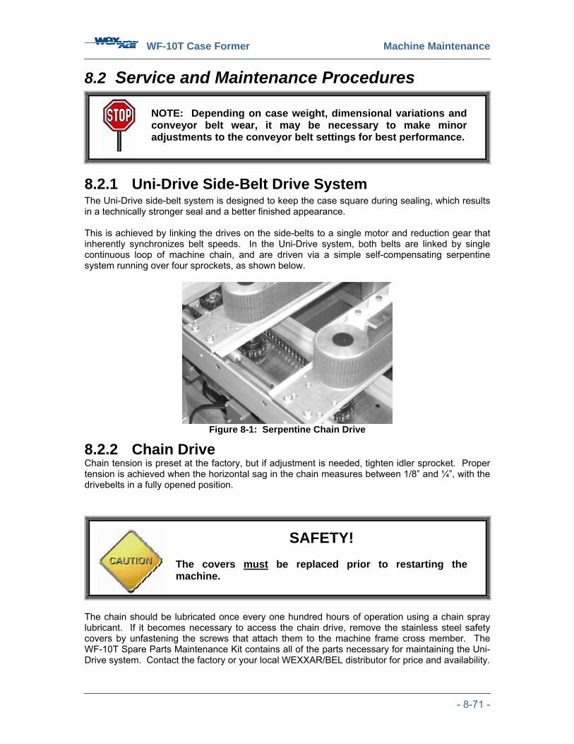
WF-10T Case Former Machine Maintenance
- 8-71 -
8.2 Service and Maintenance Procedures
8.2.1 Uni-Drive Side-Belt Drive System The Uni-Drive side-belt system is designed to keep the case square during sealing, which results in a technically stronger seal and a better finished appearance. This is achieved by linking the drives on the side-belts to a single motor and reduction gear that inherently synchronizes belt speeds. In the Uni-Drive system, both belts are linked by single continuous loop of machine chain, and are driven via a simple self-compensating serpentine system running over four sprockets, as shown below.
Figure 8-1: Serpentine Chain Drive
8.2.2 Chain Drive Chain tension is preset at the factory, but if adjustment is needed, tighten idler sprocket. Proper tension is achieved when the horizontal sag in the chain measures between 1/8” and ¼”, with the drivebelts in a fully opened position.
The chain should be lubricated once every one hundred hours of operation using a chain spray lubricant. If it becomes necessary to access the chain drive, remove the stainless steel safety covers by unfastening the screws that attach them to the machine frame cross member. The WF-10T Spare Parts Maintenance Kit contains all of the parts necessary for maintaining the Uni-Drive system. Contact the factory or your local WEXXAR/BEL distributor for price and availability.
NOTE: Depending on case weight, dimensional variations and conveyor belt wear, it may be necessary to make minor adjustments to the conveyor belt settings for best performance.
SAFETY! The covers must be replaced prior to restarting the machine.
WF-10T Case Former Machine Maintenance
- 8-72 -
8.2.3 Conveyor Side-Belt Replacement The side-belts can be easily and quickly replaced with a minimum of downtime. Wexxar/BEL recommends replacing both belts at the same time.
The procedure is as follows:
1. Remove the safety covers.
2. Loosen the lock-bolt that secures the idle pulley axle rigidly against the conveyor frame bracket. See Section 8.5.3.
3. Release the belt tension by loosening the tensioning and tracking push-pull screws until the belt can be removed upwards.
4. Fit a new belt. If the belt has a bonded lap joint, be sure to install the belt such that it is
moving in the correct direction (arrows indicate the direction). Newer ‘finger’ splice belts can move in either direction.
5. Reset the belt tension by adjusting the two push-pull screws in order to both tension and position the belt such that it is running true and not trying to ride up or down on the idler pulley. Set the belt tension such that approximately 1” of play is available when the belt is pulled sideways by hand in the center of the machine. There should be just enough tension to prevent the belts from slipping while the machine is in use. See Section 8.5.3.
6. When the correct tension and tracking are achieved, tighten the clamp bolt that locks the position.
8.2.4 Gear Reducer
Worm-gear reducers should be inspected regularly for evidence of oil leakage, excessive noise or vibration to ensure maximum performance and service life.
Oil Leakage - Check housing bolts; tighten if necessary. Replace oil seals if required.
Oil Temperature - Worm-gear reducers usually run warm through an initial run-in period. Check the temperature of the reducer for elevated temperatures (above normally encountered levels) that are not attributable to a rise in ambient temperature. Low or high oil levels and abnormal loading are possible reasons for elevated temperatures.
Sound Level and Vibration - Excessive vibration, or a change in sound level, can indicate a low oil level, abnormal loading, or worn elements.
Dirt Accumulation - Excessive accumulation of dirt or grease will affect the proper cooling of the unit.
WF-10T Case Former Machine Maintenance
- 8-73 -
8.2.5
8.3 Maintenance 8.3.1 Non-Lube Pneumatic System Maintenance A coalescing-type mist separator that effectively removes 99.9% of oil mist from incoming air. Combined with pre-lubricated air cylinders and valves, this provides reliable pneumatic operation.
Maintenance • Drain the mist separator bowl frequently.
• As the mist separator becomes contaminated, the pressure drop across the filter will increase. Replace the element when the pressure drop reaches 15 PSI, or once per year, whichever comes first.
• The rate at which the filter element is contaminated will be greatly affected by the qualify of the incoming air. If the air is wet and contaminated with lubricant, the filter element will need more frequent replacement.
8.3.2 Inspections On a daily basis, the operators should inspect for:
1) Leaks at: • Pneumatic system (air supply). • Filter bottle drain.
2) Loose fasteners.
3) Inspect the belt condition, tracking and tension
4) Irregular noise or signs of machine wear.
Check the ‘S’ box for Satisfactory Performance and ‘US’ box for Unsatisfactory Performance.
Table 23: Machine Inspection Maintenance and Cleaning Inspection S US
Inspect the pneumatic system for leaks.
Inspect the drain bottle for overflow.
Inspect for loose fasteners.
Inspect the belt condition, tracking and tension.
Inspect for irregular noise and signs of wear.

WF-10T Case Former Machine Maintenance
- 8-74 -
8.3.3 Routine Operator Maintenance
Instructions • Clean the tape knife with solvent • Lubricate the blade guard with silicone
Check the ‘S’ box for Satisfactory Performance and ‘US’ box for Unsatisfactory Performance.
Table 24: Routine Operator Maintenance Maintenance and Cleaning Routine Operator Maintenance S US
Clean the tape knife with solvent.
Lubricate the blade guard pad with silicone.
8.3.4 Cleaning Tools and Materials
• Soapy water • Rag or paper towel • Filter replacements (if necessary)
Instructions • Inspect the machine daily and remove any corrugated fragment deposits that may have
accumulated.
• Regularly check the pneumatic filter bowl and filter for debris; replace the filter at suitable intervals, depending on the cleanliness level of the incoming air supply.
• An auto drain vents water automatically from the filter bowl. If necessary, clean the filter
bowl with soapy water.
WARNING!
The tape knife blade is sharp, and can cause serious injury.
CAUTION!
DO NOT use solvents for cleaning.
WF-10T Case Former Machine Maintenance
- 8-75 -
Check the ‘S’ box for Satisfactory Performance and ‘US’ box for Unsatisfactory Performance.
Table 25: Cleaning the Machine
8.4 Preventative Maintenance Schedule Daily
• Keep framework and conveyor belts clean of dirt build-up, grease and oil residues.
• Check drivebelts for wear.
• Verify that the air pressure is regulated to the proper setting (90 PSI), and that any water is drained from the filter.
• Check for worn or broken electrical and air connections.
• Visually inspect the machine for loose fasteners, leaks in the pneumatic system, and drain bottle overflow.
• Clean the tape knife on the Dekka Tape Head with solvent and lubricate the blade guard pad with WD-40 or a similar low toxicity product.
Every 3 Weeks • Lubricate Uni-Drive side-belt drive chain and width adjustment roller chain with a chain
spray lube.
• Inspect electric motor for evidence of oil leakage, noise, or vibration.
• Keep unit free of dirt. Excess accumulation of dirt or grease will affect the proper cooling of the units.
• Check belt condition, tracking, and tension.
Maintenance and Cleaning Cleaning S US
Remove any corrugated fragment deposits that have accumulated.
Check the pneumatic filter bowl filter for debris.
Clean the filter bowl with soapy water (optional).
Replace the filter bowl.
WARNING!
The blade is sharp and can cause serious injury.
NOTE: Correct tension and tracking will prolong belt and drive bearing life.

WF-10T Case Former Machine Maintenance
- 8-76 -
Every 3 Months Thoroughly clean all adjustment screws, sprockets, chain and sliding components, and then lightly grease. See Section 8.6: ‘Lubrication’ for correct grease.
• Lubricate width and height adjustment leadscrews with Food Grade Fuchs Geralyn FMG 387 lubricant.
• Remove drivebelts. Drive pulleys and idler pulley should be inspected for bearing wear
and pulley damage. Remove any dirt build-up before drivebelts are re-installed.
• Remove flap folders for servicing. Remove covers and check for worn parts.
• Check the tension of the Uni-Drive side-belt chain drive.
• Inspect all pneumatic and electrical limit switches and verify that they are properly adjusted and in good working order.
• Check for any loose or missing fasteners.
NOTE: Proper tension for the Uni-Drive side-belt chain drive is achieved when the horizontal sag in the chain measures between 1/8” and ¼” with the drivebelts in a fully opened position.
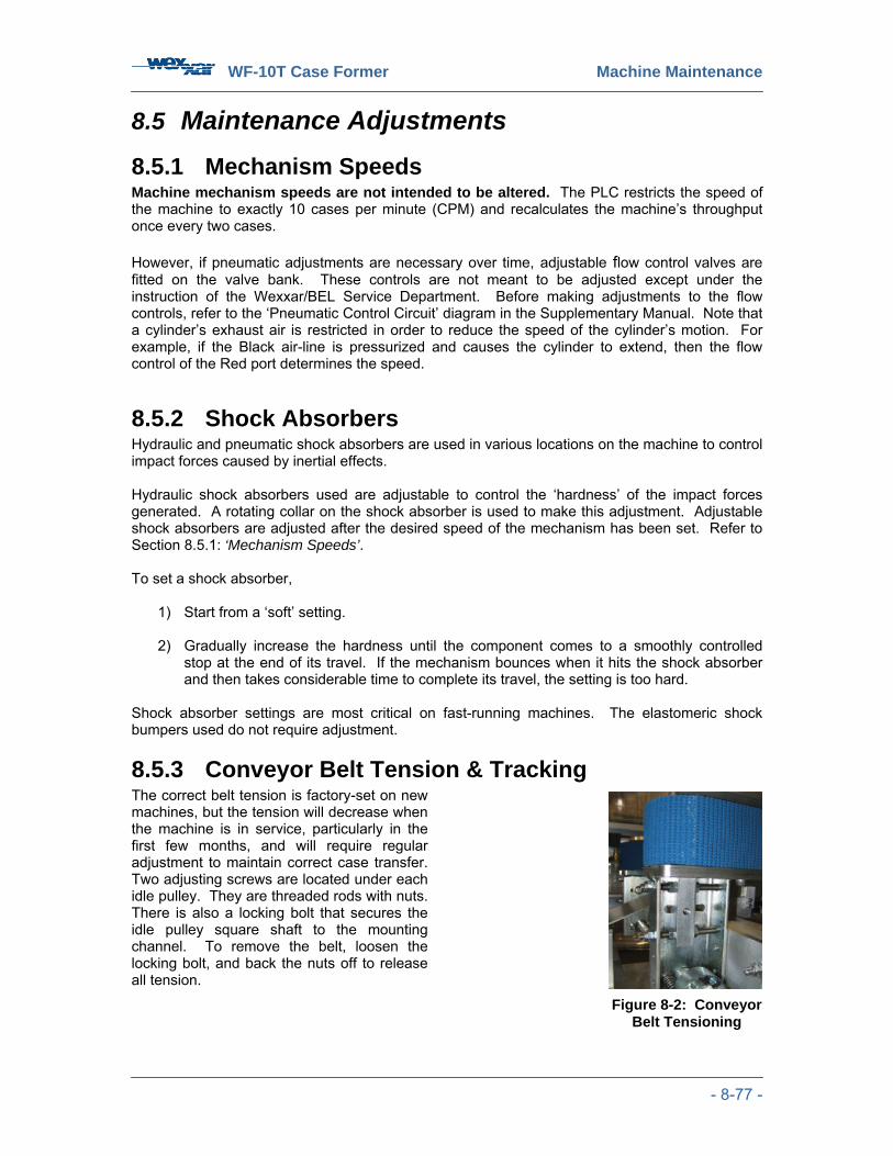
WF-10T Case Former Machine Maintenance
- 8-77 -
8.5 Maintenance Adjustments 8.5.1 Mechanism Speeds Machine mechanism speeds are not intended to be altered. The PLC restricts the speed of the machine to exactly 10 cases per minute (CPM) and recalculates the machine’s throughput once every two cases. However, if pneumatic adjustments are necessary over time, adjustable flow control valves are fitted on the valve bank. These controls are not meant to be adjusted except under the instruction of the Wexxar/BEL Service Department. Before making adjustments to the flow controls, refer to the ‘Pneumatic Control Circuit’ diagram in the Supplementary Manual. Note that a cylinder’s exhaust air is restricted in order to reduce the speed of the cylinder’s motion. For example, if the Black air-line is pressurized and causes the cylinder to extend, then the flow control of the Red port determines the speed.
8.5.2 Shock Absorbers Hydraulic and pneumatic shock absorbers are used in various locations on the machine to control impact forces caused by inertial effects. Hydraulic shock absorbers used are adjustable to control the ‘hardness’ of the impact forces generated. A rotating collar on the shock absorber is used to make this adjustment. Adjustable shock absorbers are adjusted after the desired speed of the mechanism has been set. Refer to Section 8.5.1: ‘Mechanism Speeds’. To set a shock absorber,
1) Start from a ‘soft’ setting. 2) Gradually increase the hardness until the component comes to a smoothly controlled
stop at the end of its travel. If the mechanism bounces when it hits the shock absorber and then takes considerable time to complete its travel, the setting is too hard.
Shock absorber settings are most critical on fast-running machines. The elastomeric shock bumpers used do not require adjustment.
8.5.3 Conveyor Belt Tension & Tracking The correct belt tension is factory-set on new machines, but the tension will decrease when the machine is in service, particularly in the first few months, and will require regular adjustment to maintain correct case transfer. Two adjusting screws are located under each idle pulley. They are threaded rods with nuts. There is also a locking bolt that secures the idle pulley square shaft to the mounting channel. To remove the belt, loosen the locking bolt, and back the nuts off to release all tension.
Figure 8-2: Conveyor Belt Tensioning
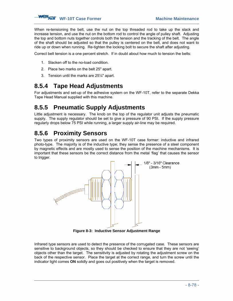
WF-10T Case Former Machine Maintenance
- 8-78 -
When re-tensioning the belt, use the nut on the top threaded rod to take up the slack and increase tension, and use the nut on the bottom rod to control the angle of pulley shaft. Adjusting the top and bottom nuts together controls both the tension and the tracking of the belt. The angle of the shaft should be adjusted so that the pulley is centered on the belt, and does not want to ride up or down when running. Re-tighten the locking bolt to secure the shaft after adjusting.
Correct belt tension is a one percent stretch. If in doubt about how much to tension the belts:
1. Slacken off to the no-load condition.
2. Place two marks on the belt 25" apart.
3. Tension until the marks are 25¼" apart.
8.5.4 Tape Head Adjustments For adjustments and set-up of the adhesive system on the WF-10T, refer to the separate Dekka Tape Head Manual supplied with this machine.
8.5.5 Pneumatic Supply Adjustments Little adjustment is necessary. The knob on the top of the regulator unit adjusts the pneumatic supply. The supply regulator should be set to give a pressure of 90 PSI. If the supply pressure regularly drops below 75 PSI while running, a larger supply air-line may be required.
8.5.6 Proximity Sensors Two types of proximity sensors are used on the WF-10T case former: inductive and infrared photo-type. The majority is of the inductive type; they sense the presence of a steel component by magnetic effects and are mostly used to sense the position of the machine mechanisms. It is important that these sensors be the correct distance from the metal ‘flag’ that causes the sensor to trigger.
Figure 8-3: Inductive Sensor Adjustment Range
Infrared type sensors are used to detect the presence of the corrugated case. These sensors are sensitive to background objects, so they should be checked to ensure that they are not ‘seeing’ objects other than the target. The sensitivity is adjusted by rotating the adjustment screw on the back of the respective sensor. Place the target at the correct range, and turn the screw until the indicator light comes ON solidly and goes out positively when the target is removed.
WF-10T Case Former Machine Maintenance
- 8-79 -
8.5.7 Mechanical Maintenance • Observe the machine in operation, looking particularly for any uneven or excessively
noisy motions and abnormal air leaks.
• With the machine stopped and the air OFF, check for smooth action without excessive bearing wear or abnormal looseness of all moving parts. See Section 8.5: ‘Maintenance Adjustments’ for further details.
• Inspect the machine for signs of abnormal wear, such as debris caused by scraping or grinding together of parts. All piston rods on the air cylinders should be smooth and shiny.
• Watch for signs of improper belt tensioning, such as the belts slipping when transporting a heavy case. Correct belt tension is one percent stretch from the no-load position - if in doubt, slacken the belt to no-load, make marks on the belt "25 apart, and re-tension to produce a distance of "25 4
1 between the marks. Always tighten tension bolts equally to maintain correct tracking. See Section 8.5.3.
• Carefully observe the conveyor side drivebelts and watch for signs of uneven wear (edge
fraying) which can occur if a belt is not tracking on-center of the pulleys. Adjust belt tension and tracking as shown in Section 8.5.3: ‘Conveyor Belt Tension & Tracking’.
• Observe the motor that drives the drivebelts for signs of oil leakage; if serious leakage
occurs, replace the motor.
• If everything appears to be operating normally, switch the machine ON and observe carefully as it processes a case, listening for signs of air leakage or other abnormal noises.
• All mechanical actions should be smooth and free of shock at the end of the stroke.
8.6 Lubrication The main components that require lubrication are:
• Leadscrews
• Chains and Sprockets
• Sliding Components
• Gear Reducers
8.6.1 Moving Components All adjustment screws, chains and sprockets, and other sliding components, should be thoroughly cleaned and lightly greased weekly. Use Food Safe Fuchs Geralyn FMG 387 lubricant or equivalent.
8.6.2 Ball Bearings All ball bearings used on Wexxar/BEL packaging machines are sealed-for-life, and regular lubrication is not required.
8.6.3 Tape Head The DEKKA WEX-22 Series Tape Heads are designed as a low maintenance item, and should not require lubrication in normal use. The felt pad on the inside of the knife guard cover should be lubricated with WD-40 or a similar low-toxicity lubricant every few days. This will prevent adhesive build-up and lengthen the life of the cut-off knife.

WF-10T Case Former Machine Maintenance
9-80
9 TROUBLESHOOTING & REPAIRS
9.1 Safety Safety Features To safely work on the machine, disconnect the compressed air supply and power supply. The guard doors around the WF-10T will ensure that you do not accidentally enter the machine’s working cell while its components are energized. Never attempt to disable any of the safety features or enter in through the discharge end while the machine is still powered. An ‘EMERGENCY STOP’ button is provided to immediately halt all machine operation by cutting off air supply and electrical power. This button should be pushed IN to stop the machine in case of an emergency.
Precautions • The WF-10T Case Former is equipped with safety interlocks. Do not attempt to disable
the interlocks when repairing the machine. • Do not use the ‘EMERGENCY STOP’ button as the sole means of isolating power to the
machine. Disconnect power at the main breaker panel and lock it out before undertaking repairs.
WARNING!
Any work that involves entering the control panel must be carried out by a qualified electrician.
WF-10T Case Former Machine Maintenance
9-81
9.2 General Troubleshooting The most common error in troubleshooting packaging machinery problems is an incorrect diagnosis of the problem. Errors cause much lost time and needless expense and are avoided by a careful analytical approach before attempting corrective action. Always start by ensuring that all case size adjustments have been made correctly. Refer to Section 7: ‘Case Size Adjustments’.
Establish whether a problem is mechanical, pneumatic, or electrical in nature.
• If a pneumatic or air-powered mechanism fails to operate properly, first switch OFF the air and attempt to move the mechanism by hand.
• If the system moves freely, no mechanical problems are indicated, and the air can be switched ON. Now operate the appropriate solenoid valve manually.
• If the mechanism moves normally when the valve is actuated manually, then the pneumatic system is working and the problem is electrical in nature. It may be that the solenoid coil on the valve has failed, or it may be that there is a problem with the signal reaching the valve.
Continue this diagnostic systematic approach until the exact malfunctioning component has been isolated; corrective action will then usually be obvious.
The following is a list of some common mechanical problems that can occur, and suggestions for dealing with them. More advanced troubleshooting may require special training.
WARNING! Switching OFF the air pressure is very important, as air cylinders can store energy and cause serious injury if suddenly released from a jammed condition.

WF-10T Case Former Machine Maintenance
9-82
Table 26: General Troubleshooting Reference Problem Possible Cause Remedial Action
Case buckles or tears during separation
Bottom Flap Height Dimension ‘M’ datum set too high
Set Dimension ‘M’ lower.
If case separator is not too high, then Case Blank Height Dimension ‘B’ likely set too low
Adjust Dimension ‘B’ up to suit actual case blank height.
Jawplates may not be parallel
Ensure that pinblocks are mounted on jawplate without obstructing each other.
Case buckles or tears during injection
Injector DOWN speed too fast Set for moderate injection speed.
Flap inner facing passes between pins & jawplate, pin sometimes catches the opposite (wrong) flap
Pins too far from jawplate
Check pins not bent out. Check pinblocks installed with narrow gap to jawplate.
Case rises while moving into side-belt conveyor, bottom flaps not up tight
‘D3’ set too wide Decrease conveyor width setting.
Case hesitates when moving through tape application section
‘D3’ width adjustment too wide Decrease conveyor width setting.

WF-10T Case Former Machine Maintenance
9-83
9.3 Machine Sequence Troubleshooting The machine sequence is controlled by a PLC located inside the electrical enclosure. The controller responds to inputs from the panel buttons and various sensors on the machine mechanisms, and it provides outputs that control the solenoid valves in the pneumatic system. The most common reason for machine sequence malfunction is incorrect sensor operation. The following series of ‘quick checks’ can be carried out by simply observing the rear of the sensor to see if it is illuminated when it should be. This procedure requires access to the inside of the control enclosure in order to observe I/O signals on the programmable logic controller, and should only be attempted by a qualified electrician adhering strictly to proper safety procedures. To troubleshoot the machine sequence, refer to Section 6.2: ‘Start-up’. While in JOG mode, step the machine through its operating sequence by pressing the ‘START’ button briefly for each step. Follow the sequential listing starting on the next page to investigate any problems that may occur. Table 27: Machine Sequence Troubleshooting
Step Sequence Problem Description Remedial Action
Machine will not start
Machine has sufficient power and air pressure, but will not start.
Magazine case supply too low; Empty Magazine Fault.
Load more case blanks and then press ‘RESET’.
Either Bottom Flap Height Dimension ‘M’ datum set too high or Case Blank Height Dimension ‘B’ set too low.
Adjust Dimension ‘B’ up to suit actual case blank height or adjust Dimension ‘B’ to measured height of case blank.
Case buckles when case separator pushes it into caliper slot.
Insufficient down-force applied to case blanks in magazine; add more cases and ensure that cases are tight against the backing plate.
Case Separation
Case buckles when case separator elevates case blank into caliper slot.
Injector DOWN speed too fast.
Set for moderate injection speed.

WF-10T Case Former Machine Maintenance
9-84
Step Sequence Problem Description Remedial Action
Case jams when injected into the jawplate pins.
Jawplates are not parallel when the carriage is in its RETRACTED position.
Ensure that pinblocks are mounted on jawplate without obstructing each other. Case Injection
Case does not inject all the way onto the jawplate pins.
Bottom Flap Height Dimension ‘M’ datum set too high.
Set Dimension ‘M’ lower.
Carriage Forward
Jawplates make contact with conveyor assembly.
Dimension ‘C’ is set too far forward towards the discharge end of the machine.
Set ‘C’ further away from conveyor assembly.
Case blanks are loaded with the glue lap towards the infeed end of the magazine.
Cases are loaded upside-down
Jawplates Pivot
Case opens sideways from normal orientation. Machine set up for
wrong-handed case blanks
See Section 5.7.
Minor flaps bent upwards beyond horizontal position by major flap folding action.
Conveyor Formed Case Width Dimension ‘D3’ set too narrow.
Adjust ‘D3’ slightly wider.
Flap Folding
Rear flap folder pushes bottom rear flap up too high.
Bottom Flap Height Dimension ‘M’ set too high.
Adjust Dimension ‘M’ handcrank slightly higher, lowering the rear flap folder assembly (which uses an inverted scale).
Tape Application and Discharge
See Section 9.7: ‘Case Drivebelt System Troubleshooting’, and Section 9.9: ‘General Tape Applicator Troubleshooting’.

WF-10T Case Former Machine Maintenance
9-85
9.4 Electrical Troubleshooting
The electrical control circuit drawing is required for reference and diagnostics. A copy of the electrical control circuit is in the electrical control cabinet and in the Supplementary Manual.
Close the guard doors, and make sure the ‘EMERGENCY STOP’ button is in the OUT position by turning the knob 8
1 turn clockwise.
Confirm that:
1. All lines into the machine, as listed on the electrical control nameplate in the control panel, have the correct voltage.
2. The fuses on the disconnect switch are operating properly.
3. The disconnect switch is ON ( 41 turn clockwise).
4. The PLC terminals (‘IN+’ and ‘IN-‘, ‘DC24+’, and ‘DC COM’) are all operating at 24 V DC.
In the unlikely event that LEDs are illuminated improperly, and you do not have the appropriate PLC interface, or training, contact WEXXAR's service department. Without the appropriate equipment and training to correct this status, there is nothing else that you can do.
Allow the air pressure to bleed off before attempting any adjustments or replacement of suspected faulty components.
WARNING! THE ELECTRICAL CONTROL CABINET CONTAINS MULTIPLE VOLTAGES. THE FOLLOWING WORK MUST BE CARRIED OUT BY A QUALIFIED ELECTRICIAN, AND APPROPRIATE SAFETY PRECAUTIONS MUST BE FOLLOWED.
WARNING! TURN OFF THE MANUAL AIR VALVE AND ELECTRICAL POWER.
NOTE: Many of the input signals to the PLC originate from inductive or optical sensors as noted on the electrical control circuit. Without a target, they are similar to a normally open (‘NO’) switch. With a target in their sensing range, they turn ON and act like a closed switch. These sensors are equipped with an LED on the wire lead end of their housing. These LEDs are turned ON when the target is in their sensing range.
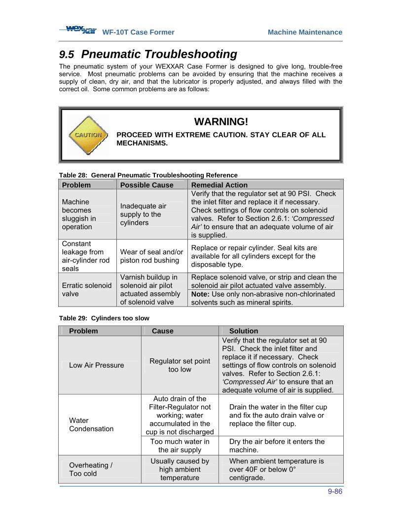
WF-10T Case Former Machine Maintenance
9-86
9.5 Pneumatic Troubleshooting The pneumatic system of your WEXXAR Case Former is designed to give long, trouble-free service. Most pneumatic problems can be avoided by ensuring that the machine receives a supply of clean, dry air, and that the lubricator is properly adjusted, and always filled with the correct oil. Some common problems are as follows:
Table 28: General Pneumatic Troubleshooting Reference Problem Possible Cause Remedial Action
Machine becomes sluggish in operation
Inadequate air supply to the cylinders
Verify that the regulator set at 90 PSI. Check the inlet filter and replace it if necessary. Check settings of flow controls on solenoid valves. Refer to Section 2.6.1: ‘Compressed Air’ to ensure that an adequate volume of air is supplied.
Constant leakage from air-cylinder rod seals
Wear of seal and/or piston rod bushing
Replace or repair cylinder. Seal kits are available for all cylinders except for the disposable type.
Replace solenoid valve, or strip and clean the solenoid air pilot actuated valve assembly. Erratic solenoid
valve
Varnish buildup in solenoid air pilot actuated assembly of solenoid valve
Note: Use only non-abrasive non-chlorinated solvents such as mineral spirits.
Table 29: Cylinders too slow
WARNING! PROCEED WITH EXTREME CAUTION. STAY CLEAR OF ALL MECHANISMS.
Problem Cause Solution
Low Air Pressure Regulator set point too low
Verify that the regulator set at 90 PSI. Check the inlet filter and replace it if necessary. Check settings of flow controls on solenoid valves. Refer to Section 2.6.1: ‘Compressed Air’ to ensure that an adequate volume of air is supplied.
Auto drain of the Filter-Regulator not
working; water accumulated in the
cup is not discharged
Drain the water in the filter cup and fix the auto drain valve or replace the filter cup. Water
Condensation
Too much water in the air supply
Dry the air before it enters the machine.
Overheating / Too cold
Usually caused by high ambient temperature
When ambient temperature is over 40F or below 0° centigrade.

WF-10T Case Former Machine Maintenance
9-87
Table 30: Cylinders not moving Problem Cause Solution
Compressed air not connected Connect air supply.
Mechanical Jam Clear mechanical jam.
Socket loose Tighten socket. Open Circuit
Cable broken Replace cable.
Overheating / Too cold
Usual cause is high ambient temperature
When ambient temperature is over 40F or below 0° centigrade.
Auto drain of the Filter- Regulator is not working; water accumulated in the cup is not discharged
Drain water in the filter cup and fix the auto drain valve or replace the filter cup. Water
Condensation Too much water in the air supply
Dry the air before it enters the machine.
9.6 Corrugated Case Quality Troubleshooting Corrugated case quality is a major contributor to smooth machine operation and output quality. The following points will help determine if you have a case size or quality problem:
1. Case dimensions. Using the right size of case and weight of material can often result in cost savings.
2. Score (fold) lines. Make sure that the scores in all of your cases are as well defined as possible in order to help with the automatic folding process. This is one of the most common causes of poor case closing performance. Your corrugated case supplier can help make sure that the correct pressure is applied during case scoring for your case specification.
3. Corrugated case weakness. The case manufacturing process can damage the fluted construction of corrugated board. Store flat cases in dry conditions and on a flat surface. Be careful not to stack excessive weight on cases, as crushing of the flutes will result.
Points to watch for include:
a. Overall crushing of the corrugated flutes, causing the case to have a ‘soft’ and limp feeling. This condition results in poor machine handling and may not give your product the required protection. b. Selective bands of crushing, usually parallel to the case flutes, can cause failure lines down the case and result in poor machine performance.
4. Case ‘squareness’. Check the corner joint where the manufacturer glues the flat case together; it can often be out of alignment, making the case wider at one end than the other, or twisted from end to end. It can also cause machine jams and poor quality case sealing. 5. Flap corner slots. Corner slots should be as wide as possible so that the flaps can be manually or automatically folded with a minimum of interference. 6. Flaps overlap or are gapped (major flaps). Overlapping flaps are a result of incorrect flap lengths. Fold a case by hand to verify that flaps meet neatly at the center.

WF-10T Case Former Machine Maintenance
9-88
9.7 Case Drivebelt System Troubleshooting The Uni-Drive side-belt system is designed to keep the case square during sealing, which results in a technically stronger seal and a better finished appearance. This is achieved by linking the drives on the side-belts to a single motor and reduction gear, which inherently synchronize belt speeds. In the Uni-Drive system, both belts are linked by single continuous loop of machine chain, and are driven via a simple self-compensating serpentine system running over four sprockets.
9.7.1 Case Not Sealing Squarely Despite the parallel drive nature of the Uni-Drive system, the cases exit the machine out-of-square after sealing. Verify that:
• the case is square prior to engagement in the conveyor side-belts. • neither of the conveyor belts is slipping on its drive pulley. See the belt tensioning
procedure under Section 8.2: ‘Service and Maintenance Procedures’. • the side-belts are correctly adjusted to the case width by the following method:
1. Adjust the belts inward until they lightly contact the case sides. The case should still be able to slide through the side-belts if pushed firmly. 2. Remove the case and adjust the belts inward by another half-turn.
9.7.2 Crushed Band on Bottom of Case’s Side Panels If the cases exit the machine with a band of crushed corrugation at the level of the conveyor belts, it is likely that the cases have been gripped too tightly by the belts.
9.7.3 Belt Sheds Rubber ‘Dust’ A belt-colored dust appears beneath the conveyor belts, particularly at the discharge end of the machine. Verify that:
• the case is clearing the belts as it exits the machine, and that outfeed conditions do not cause cases to back-up into the machine.
• belt tensioning and tracking adjustments are correct as described in Section 8.2: ‘Service and Maintenance Procedures’.
Incorrect settings can cause premature belt wear and possible belt breakage.
9.7.4 Conveyor Drive Rattles Audibly Although pre-stretched chain is used in the machine drive, over time the chain may loosen and rattle on the drive cover. Tighten the idler sprocket as described in Section 8.2: ‘Service and Maintenance Procedures’.

WF-10T Case Former Machine Maintenance
9-89
9.7.5 Cases Jam Frequently Between Belts
Turn OFF the machine as soon as a jam occurs and before clearing the jam.
Check for the following jam causes:
• Tape head may be adjusted too high.
• Bottom flaps are not folding correctly, flaps then hit center ski or tape head mechanism. If the tape head is mounted too high, interfering with the transit of cases over the tape head, slide the tape head out and remove it from the bracket. Then use a wrench to loosen the bolts that secure the discharge end of the tape head bracket to the main frame. Adjust the bracket down slightly in the adjustment slots and retighten the bolts.
Figure 9-1: Lowering the Tape Head Bracket
9.7.6 Frequent Belt Breakage Belt service life will depend on the conditions of machine use, but frequent breakage may be due to one or more of the following conditions:
• Belt tracking. Verify that the belt does not try to ride up or down on the pulleys. See belt tensioning and tracking adjustment in Section 8.2: ‘Service and Maintenance Procedures’.
• Belt Tension. Belts may be over-tensioned – there should be approximately 1” of slack
at the center point of the conveyor.
• Idler and drive pulley rotation. Verify that the pulleys rotate freely and that bearings are not excessively worn or seized.
• Rotation direction of belt. Look on the back of the belt for the type of join. Stepped-lap
splice belts must move in the direction of the arrow marked on the inside of the belt. Newer style ‘finger-spliced’ belts can move in either direction.

WF-10T Case Former Machine Maintenance
9-90
9.8 Bottom Flap Folding Troubleshooting
The WF-10T is unique among fully automatic bottom flap folding machines in that it employs a unique system of flap folding technologies working in unison. The function of the flap folders is to integrate the folding of the minor flaps and major flaps within the shortest possible time and travel distance.
9.8.1 Rear Minor Flap Does Not Fold • Ensure that air pressure is maintained at the correct machine setting, and that adequate
air volume is being consistently delivered. Lack of air pressure and/or volume can result in poor flap folding performance.
• Verify that the scoring on the flaps is adequate, and that they will fold easily and cleanly.
• Cases with flaps shorter than 3” may have to be run on a modified machine.
9.8.2 Rear Flap Folds, Releases, and Turns Backwards
• Verify that the center ski is set in its correct position;
a. for cases with small minor flap heights, set the ski towards the infeed end of the conveyors.
b. for cases with median minor flap heights, set the ski near the middle of the adjustment slot.
c. for cases with large minor flap heights, set the ski towards the discharge end of the machine.
9.8.3 Bottom Major Flaps Bind On Center Ski • Verify that excessive lateral pressure has not been applied to the case, causing the flaps
to bind on the vertical side of the ski.
9.8.4 Major Flaps Overlap in Center of Case • Check for excessive lateral pressure from the belts.
• Verify that the flaps are not too long as a result of a poorly manufactured case.
9.8.5 Bottom Major Flaps Have a Gap in Center • Verify that side-belt compression is squeezing bottom flaps together.
9.8.6 Major Flap Leading Edges Wrinkle After Taping • Verify that the tape head is not adjusted too high.
• Ensure that the tape head bracket has not been set too high
NOTE: This adjustment is used for extremes of range, and should normally be set in the middle position.

WF-10T Case Former Machine Maintenance
9-91
9.8.7 Major Flaps Have a Tapered Gap or Gap / Overlap Combination
• Verify that case dimensions are square.
• Verify that the tape unwind tension is not excessive. This can cause the major flaps to be pulled back, causing a rear gap.
9.8.8 Major Flaps Fold, but Leading Edge Lifted by Tape and Folded Back
• Tape head may be set too low.
• Check to ensure that the tape head bracket has not been set too low. Positioning is normally factory pre-set. Adjustments may have to be made on a ‘trial and error’ basis until optimum setting has been obtained.
If the tape head is mounted too low, slide the tape head out and remove it from the bracket. Then use a wrench to loosen the bolts that secure the discharge end of the tape head bracket to the main frame. Adjust the bracket up slightly in the adjustment slots and retighten the bolts.
Figure 9-2: Elevating the Tape Head Bracket

WF-10T Case Former Machine Maintenance
9-92
9.9 General Tape Applicator Troubleshooting
Comprehensive information on the set-up, operation, and maintenance of the adhesive system on the WF-10T is contained in the separate Dekka Tape Head Manual supplied with this machine.
9.9.1 Tape Does Not Stick To Case Surface The tape is not bonding to the corrugated board of the flaps or ends of the case to provide a secure seal. Look for the following conditions:
• Overlapping flaps. If the major flaps are allowed to overlap, the ‘step’ that is created results in an uneven taping surface, causing poor tape adhesion that can result in tape detachment during shipping and handling. See comments on flaps under Section 9.6: ‘Corrugated Case Quality Troubleshooting’.
• Tape head roller contact. Verify that the tape head contact or wipe-down rollers are
making good contact with the case, and that the roller spring tension is correct.
• Dust or dirt. Large amounts of dust or dirt accumulating on cases or in the air will impair adhesive effectiveness.
• Temperature. Hot or cold temperatures may require tapes with appropriate adhesive
formulations for good initial bond and permanent sealing performance.
• Tape adhesive. Check the presence and quality of the tape adhesive.
WARNING! Before undertaking repair work, ALWAYS ensure that the Main Air Pressure and Electrical Supplies are locked OFF.

WF-10T Case Former Machine Maintenance
9-93
9.9.2 Tape is not Cut Uniformly The tape is not cut properly every time. In the worst situations, several cases may be taped together.
Check the following conditions:
• Tape head position. If the tape head is set too high, the cut-off knife will not be fully activated, resulting in poor cut-off. The tape head side plates should be within 1/16” and 1/8” of the case. Verify also that cases ride fully down between the conveyor belts to provide proper contact with the tape head cut-off knife.
• Knife extension. Be sure that the knife extends enough to fully contact the tape during the cutting stroke.
• Tape tension. Unroll tension should be smooth and not too tight, as a ‘snap back’ caused by stretched tape can cause a jagged cut-off, and tape pieces may stick to the blade.
• Clean knife. Clean the blade and apply a little silicon or oil to avoid adhesive build-up on the sharp points.
• Knife blade wear or damage. Blades must be very sharp to work well. The points are
easily damaged if contacted by any hard material. Replace the blade if it seems dull.
• Cut-off spring tension. Verify that the spring that provides power to the cut-off arm has enough tension to cut through the tape. Replace the spring if it is too weak.
9.9.3 Tape Tail does not Stick Down Properly The end of the tape on the rear side of the case as it leaves the machine has not adhered well to the case. Check for the following conditions:
• Tape tension. Tension should be smooth and not too tight. ‘Snap-back’ will cause tape tail to recoil and to adhere poorly on the rear of the case.
• Tape head roller contact. Tape head contact or wipe-down rollers should make good
contact with the case. Adjust roller spring tension if necessary.
CAUTION!
The tape head knife is very sharp!
WF-10T Case Former Machine Maintenance
9-94
9.9.4 Tape is Off-center The line of tape is not centered over the gap between flaps on the bottom of the case. Look for the following conditions:
• Tape roll position. Verify that the tape roll is fully pushed onto the spool.
• Tape head straight. Verify that the tape head sits straight in its bracket, and is not tilted to either side.
• Obstructions. Look for obstructions that could be pushing the tape off-center.
9.9.5 Tape Falls Forward on Tape Head The beginning end of the tape must stand vertically in front of the tape head front roller in order to contact the leading end of the next case. A bow made across the tape by the tape head guides helps to stiffen the tape, and a static electric charge on the tape head rollers attracts the tape and helps to keep it in place. If the tape will not stand vertically, examine the following factors:
• Contamination. The tape may be wound around the roller or there may be dirt on the roller.
• No static charge. Dust the roller surfaces with talcum powder to increase the static charge on the roller.
• Tape head guides. Verify that the tape holder, or finger, is set correctly. See tape head manual.
• Ambient conditions. A strong breeze in the vicinity of the tape sealer can cause the tape to blow down. High temperature or humidity may affect tape characteristics.
• Type of tape. Some brands and types of tape have more ‘body’ than others, and a change of tape may be needed, particularly in difficult ambient conditions.
9.10 Repair Procedures The operating time before significant wear will occur with WEXXAR packaging machines depends upon the service duty to which the machine is subjected, and can vary widely between different customers. Many wear points are quite simple (bushings, rod ends, etc.), and the corrective action is self-evident. Some repair jobs requiring special attention are described in the following paragraphs. Please also refer to the assembly drawings in the Supplementary Manual, which contain much helpful information and all necessary part numbers.
9.10.1 Solenoid Valve Repairs The valves are designed for easy replacement.
1) Lock the air OFF at the manual shutoff valve upstream of the filter-regulator unit.
2) Lock OFF the electrical power.
3) Remove the two screws that secure the valve body to the manifold block.
4) Replace the complete valve/solenoid assembly, taking care to properly install the gasket to prevent leakage.
Overhaul of valve/solenoid assemblies can be undertaken, but this must be carried out in a clean area. Clean the solenoid air pilot actuated assembly with clean mineral spirits if necessary.
WF-10T Case Former Machine Maintenance
9-95
9.10.2 Conveyor Drivebelt Repairs To change the drivebelts,
1) Slacken the belt-tensioning nuts to the fully BACK position. This will permit belt removal by starting at the idle pulley end, and lifting the belt off upwards and back.
2) Replace with a new belt.
3) Make marks 25" apart on the belt before any load is applied.
4) Tension the belt by tightening the tensioning screws equally to achieve a measurement of 25¼" between the marks (1 percent stretch).
5) Run the belts to ensure correct tracking. If necessary, tighten the tensioning screw on the side that the belt moves towards.
9.10.3 Drivebelt Bearings Repairs All drivebelts run on sealed ball bearings, which are lubricated for life. Should bearing failure occur, the entire bearing and housing should be replaced.
9.10.4 Gearmotor Repairs Should failure of these components occur, replacement is recommended. The gearmotor shaft ‘plugs into’ the drive pulley that is mounted to the conveyor bottom plate. Refer to the assembly drawing in the Supplementary Manual for more information and part numbers.
WF20T Case Former Engineering Specifications
10-96
10 ENGINEERING SPECIFICATIONS 10.1 Operating Parameters
Table 31: Operating Parameters Safety Guarding Integrated safety guarding with keyed interlock switches.
UL/cUL listed standard electrical control panel, NEMA 12. Meets NFPA-79 standard. Built-in 24V DC power supply for safe, low voltage sensors and operating controls.
Controls
PLC operated sequence and timing control. Power Requirement 120V AC, 1-phase, 60Hz (other voltages available).
Speed Approximately 10 Cases Per Minute depending on case size and quality.
Air Requirement 6 SCFM Tape System DEKKA Model WX-22 tape applicator head. Other makes optional. Approx. Weight 1,800 lbs (820 kg).
Case Styles RSC (Regular Slotted Case); HSC (Half Slotted Case); other styles available upon request.
Change-Over Time Approximately 10 – 15 minutes. Safety Compliance Lock-out provision on main electrical and air shutoffs.

WF20T Case Former Training Guide
11-97
11 TRAINING GUIDE 11.1 Performance Checklists To instruct trainees in the performance and operation of the machine, use the Performance Checklists found throughout this manual, notably in Section 6: ‘Operating Procedures’, Section 7: ‘Case Size Adjustments’, and Section 8: ‘Machine Maintenance’.
Refer to the following Performance Checklist Tables:
Table 32: Performance Checklists Table # Performance Checklist Section
5 Preliminary Start-up Checklist 6.2.1 7 Machine Start-up Procedures 6.2.2 8 Machine Loading Checklist 6.3.3 9 Clearing Jams 6.4
10 Machine Shutdown 6.5 12 Dimension ‘A’ Adjustments 7.6 13 Dimension 'M' Adjustments 7.7 14 Dimension 'B' Adjustments 7.8 15 Dimension 'D1' Adjustments 7.9 16 Horizontal Pinblock Adjustment 7.9.1 17 Pinblock Mounting Orientation 7.9.2 18 Dimension 'D2' Adjustments 7.10 19 Dimension 'D3' Adjustments 7.11 20 Dimension 'C' Adjustments 7.12 23 Machine Inspection 8.3.2 24 Routine Operator Maintenance 8.3.3 25 Cleaning the Machine 8.3.4
WF20T Case Former Training Guide
11-98
11.2 Instructions for Assessing Performance Before the Performance Assessment
1. Verify that the work area conforms to all safety standards.
2. Verify that tools, equipment, and material needed to perform the task are on hand.
During the Performance Assessment 1. Give the trainee the performance checklist.
2. Read all instructions aloud word for word.
3. Stress the importance of following all safety standards.
4. Ask the trainee the following question: “Do you understand exactly what you are to
perform and the standards you must demonstrate to successfully complete the performance assessment?”
5. Record the start and stop times.
6. Check each block of the performance checklist as the trainee satisfactorily performs the
step.
7. Stop the trainee any time that a step is scored as unsatisfactory and at the end the evaluation.
8. Sign and date beside each checklist as it is completed.
9. Have the trainee sign and date beside each checklist as it is completed.
After the Assessment 1. Collect all performance checklists.
2. Verify that the work area has been cleaned up.
3. Verify that the work area is safe.
4. Review the performance assessment with the trainee.
5. Forward all records to the Training Department.

WF-10T Case Former Service & Warranty
12-99
12 SERVICE & WARRANTY Service The WEXXAR organization is committed to providing an exceptionally high level of support to all of its customers and their installed equipment. WEXXAR maintains a comprehensive inventory of replacement parts, as well as factory trained technical representatives for consultation, installation and start-up, customer employee training, in-plant service, or complete rebuilding of equipment. To order parts or arrange for service, please call or fax us.
Warranty Machinery and parts manufactured by WEXXAR are warranted for a period of one year from date of shipment against failure or defective workmanship. Components purchased from other manufacturers by WEXXAR are warranted for the duration of the manufacturer’s warranty. This warranty does not extend to parts that may presumably be expected to wear out during the warranty period. Damage caused by misuse, improper maintenance, negligence, or accident shall void the warranty on the equipment. The warranty provides for replacement of parts proven defective within one year of shipment of the machine. This warranty does not cover shipping costs; defective parts should be returned prepaid to the Factory. This warranty shall be the only warranty in effect, and is made exclusive of all other warranties and guaranties, written or oral, expressed or implied. WEXXAR does not accept responsibility for consequential or incidental damage of any kind.

WF-10T Case Former Options
13-100
13 OPTIONS 13.1 Tape Monitoring System The tape monitoring system alerts the machine attendant when a taping fault occurs, and when it is time to replace the tape roll. A tape-roll-follower arm is fitted to the machine. A small wheel mounted on the end of the follower arm makes contact with the tape roll. As tape is applied to the case, rotation of the small wheel creates a pulsating signal to indicate that tape is fed out. When the case leaves the tape application zone, the tape roll stops and the pulsating signals stop. The follower arm also includes a flag that works with a sensor to warn when the tape roll is getting low.
1. ‘No Tape’ Monitor: If tape is not applied to the case when the case passes the tape head (e.g., if the tape web is broken or the tape roll is empty), then pulsating signals will not be present and the machine will shutdown on a ‘No Tape Applied’ logic test. The Red beacon illuminates until the machine is RESET or RESTARTED. Note that the illuminated Red beacon can also indicate other machine fault conditions.
2. ‘Tape Running’ Monitor: If tape is not cut at the end of the case, and the discharged case continues to pull tape off the roll, the pulsating signals continue longer than programmed, and the machine shuts down on a ‘Tape Running’ logic test. The Red beacon illuminates until the machine is RESET. Note that the Red beacon will be also become illuminated if an emergency stop condition exists or if a guard door is open. It is thus possible to have multiple beacon alarm conditions at once.
3. ‘Low Tape’ Monitor: When the tape roll has been depleted to a preset low level, the sensor activates the flashing Amber beacon, indicating that the tape roll will have to be replaced soon. The machine logic then measures the tape length dispensed, and stops the machine when the tape roll has been depleted. The machine can be restarted to use the remaining tape.

WF-10T Case Former Index
14-101
14 INDEX
A
Adhesive Adjustments .................................. 8-78 Adjustments
Adhesive................................................... 8-78 Case Size ................................................. 7-49 Conveyor Belt ........................................... 8-77 Dimension B ............................................. 7-56 Dimension C ............................................. 7-66 Dimension D2 ........................................... 7-64 Dimension D3 ........................................... 7-65 Dimension M............................................. 7-55 Handing .................................................... 5-32 Magazine Pusher...................................... 6-45 Maintenance ............................................. 8-77 Pneumatic................................................. 8-78 Quick Size Change................................... 7-69 Reference Table ....................................... 7-69 Testing...................................................... 7-67
B
Ball Bearings................................................. 8-79 Bottom Flap Height ....................................... 7-55 Bottom Ski..................................................... 7-64 Buttons
Alarm History ............................................ 5-36 Case Orientation....................................... 5-34 Dry Cycle .................................................. 5-29 Emergency Stop .............................. 5-23, 6-48 Jog Control ............................................... 5-27 Machine Cycle Jog ................................... 5-28 Main Control ............................................. 5-25 PLC Inputs................................................ 5-37 PLC Outputs ............................................. 5-38 Remote Demand ............................. 5-30, 5-31 Reset ........................................................ 5-23 Service...................................................... 5-37 Setup ........................................................ 5-28 Start .......................................................... 5-25 Stop ................................................. 5-25, 6-48 Troubleshooting........................................ 5-37
C
Calipers......................................................... 3-14 Carriage Case Length................................... 7-66 Case Blank Height ........................................ 7-56 Case Blank Length........................................ 7-54 Case Blank Pusher ....................................... 3-14 Case Dimension Measurements ................... 7-52 Case Injection ............................................... 4-19 Case Opening ............................................... 4-19 Case Orientation .................................. 5-32, 5-35
Case Quality ................................................. 9-87 Case Sealing................................................. 4-20 Case Separation ........................................... 4-18 Case Separator ............................................. 3-14 Case Size Range .......................................... 7-53 Case Supply.................................................. 4-18 Center Ski ..................................................... 7-64 Center Ski Case Width.................................. 7-64 Chain Drive ................................................... 8-71 Chain Lock ........................................... 7-55, 7-56 Cleaning............................................... 8-73, 8-74 Clearing Jams ............................................... 6-47 Component Identification .............................. 3-10 Components.................................................. 3-14
Electrical .......................................... 3-14, 3-16 Pneumatic................................................. 3-14
Compressed Air ....................................... 1-3, 2-8 Control Panel ................................................ 3-14 Conveyor....................................................... 8-72 Conveyor Belts....................................... 1-3, 8-77 Conveyor Case Width ................................... 7-65 Cycle Operation ............................................ 5-26 Cycle Sequence............................................ 7-68
D
Dimension A Adjustment............................... 7-54 Dimension B Adjustment............................... 7-56 Dimension C Adjustment............................... 7-66 Dimension D Adjustment............................... 7-64 Dimension D1 Adjustment............................. 7-57 Dimension D3 Adjustment............................. 7-65 Dimension M Adjustment .............................. 7-55 Direct Current................................................ 3-14 Discharge Conveyor............................... 2-7, 3-14 Disconnect Switch......................................... 5-23 Dome ............................................................ 3-14 Drive Belt ...................................................... 9-88
Troubleshooting ........................................ 9-88 Drivebelt
Breakage .................................................. 9-89 Drivebelts ............................................. 3-14, 9-95
E
Electrical Disconnect..................................... 3-14 Electrical Panel ............................................. 3-14 Electrical Power ....................................... 1-3, 2-9 Emergency Stop................................... 5-23, 6-48
F
Filter ....................................................... 2-8, 3-14 Filter-Regulator ............................................... 2-9 Flap Folder
WF-10T Case Former Index
14-102
Rear.......................................................... 3-16 Flap Folders .................................................. 3-14 Flap Folding .................................................. 9-90 Front Flap Folder .......................................... 7-64
G
Gear Reducer ...................................... 3-15, 8-72 Gearmotor..................................................... 9-95 Guard Doors ................................. 1-3, 3-15, 6-48
H
Handing ........................................................ 5-32 Home Positions............................................. 6-42 Hopper .......................................................... 3-15 Hopper Guide Rail ........................................ 3-15
I
Inductive Sensors ................................ 3-15, 4-21 Infrared Sensors ........................................... 3-15 Injector .......................................................... 3-15 Inspections.................................................... 8-73 Installation................................................ 2-5, 2-6 Interlock Switches .................................. 1-4, 4-22
J
Jams ............................................................. 6-47 Jawplate Case Width .................................... 7-57 Jawplates ...................................................... 3-15 Jog ................................................................ 5-27 Jog Mode ...................................................... 5-28
L
Labels ........................................................... 7-51 Levelers ........................................................ 3-15 Leveling .......................................................... 2-7 Light Emitting Diodes (LED).......................... 3-15 Location .......................................................... 2-7 Lubricants ....................................................... 1-4 Lubrication .................................................... 8-79
M
Machine Adjustments.................................... 7-50 Machine Management ...............................13-100 Magazine Loading......................................... 6-44 Magazine Pusher ................................. 3-14, 6-45 Main Control.................................................. 5-25 Main Frame................................................... 3-15
Maintenance ............................... 8-70, 8-73, 8-74 Cleaning ................................................... 8-75 Mechanical................................................ 8-79 Pneumatic System.................................... 8-73 Preventative.............................................. 8-75 Routine Operator ...................................... 8-74
Maintenance Adjustments............................. 8-77 Manual Shut-off Valve................................... 3-15 Material Safety Data Sheets (MSDS)
Fuchs Lubricants Geralyn FMG 387 ...........104 Keystone Lubricants Nevastane HT-2 ........112
Mechanical Maintenance .............................. 8-79 Minor Flap Folders ........................................ 4-19 Monitoring ..................................................... 6-44 Motor............................................................. 3-15 Moving Components ..................................... 8-79
O
Operating Procedures ................................... 6-40 Optical Proximity Sensors ............................. 3-15 Options...................................................... 13-100
P
Parameters ................................................. 10-96 Parts
Components ............................................. 3-14 Performance Checklists .............................. 11-97 Pin and Dome ............................................... 3-17
Adjustments .............................................. 7-63 Pinblock Adjustments........................... 7-61, 7-62 Pinblocks....................................................... 3-16
Adjustments .............................................. 7-60 Mounting Orientation ................................ 7-62
Pins ............................................................... 3-15 Pneumatic Adjustments ................................ 8-78 Pneumatic Air Supply.................................... 6-48 Pneumatic System
Maintenance ............................................. 8-73 Pneumatic Valves ................................ 3-16, 4-22 Power Supply ................................................ 3-14 Preventative Maintenance............................. 8-75 Programmable Logic Controller (PLC) .......... 3-16 Proximity Sensors ......................................... 8-78 Pusher
Case Blank ............................................... 3-14 Magazine .................................................. 3-14
R
Regulator ............................................... 2-8, 3-14 Remote Demand.................................. 5-30, 5-31 Repairs................................................. 9-80, 9-94
Drivebelt ................................................... 9-95 Drivebelt Bearings .................................... 9-95 Gearmotor................................................. 9-95 Solenoid Valves ........................................ 9-94

WF-10T Case Former Index
14-103
Ringpins........................................................ 7-60
S
Safety..........................1-1, 6-40, 7-49, 8-70, 9-80 Compressed Air.......................................... 1-3 Electrical ..................................................... 1-3 Guard Doors ............................................... 1-3 Interlock Switches....................................... 1-4 Lubricants ................................................... 1-4
Safety Lock-outs ............................................. 1-3 Safety Standards ............................................ 1-2 Screens
Alarm History ............................................ 5-36 PLC Inputs....................................... 5-37, 5-38 PLC Outputs .................................... 5-38, 5-39 Setup ........................................................ 5-29 Troubleshooting........................................ 5-37
Sensors......................................................... 4-21 Inductive .......................................... 3-15, 4-21 Infrared ..................................................... 3-15 Proximity................................. 3-15, 4-21, 8-78
Sequence of Operations ............................... 4-18 Service........................................................ 12-99 Service Connections ....................................... 2-8 Shock Absorbers.................................. 3-16, 8-77 Shutdown...................................................... 6-48 Side Belt
Replacement ............................................ 8-72 Side Belt Drive .............................................. 8-71 Side-Belt Conveyor ....................................... 3-14 Solenoid ............................................... 3-16, 9-94 Solenoid Valve Bank..................................... 4-22 Specifications.............................................. 10-96 Speed ........................................................... 8-77 Start-up ......................................................... 6-41 Start-up Procedures...................................... 6-42 Switches
Disconnect....................................... 5-23, 6-48 Interlock .................................................... 4-22
Synchronization Bar ...................................... 7-58
T
Tape Tape Head.............................. 3-16, 8-79, 9-92
Tape Applicator ............................................. 9-92 Troubleshooting ........................................ 9-92
Tape Heads Installation................................................... 2-9
Touchscreen ................................................. 5-24 Training Guide............................................. 11-97 Troubleshooting ............................................ 9-80
Drivebelt ................................................... 9-88 Electrical ................................................... 9-85 General ..................................................... 9-81 Machine Sequence ................................... 9-83 Pneumatic................................................. 9-86 Tape Applicator......................................... 9-92
U
Uni-Drive ....................................................... 8-71
V
Valve Numbers.............................................. 6-42 Valves
Pneumatic........................................ 3-16, 4-22 Solenoid........................................... 3-16, 9-94
Vertical Adjustment .............................. 7-55, 7-56
W
Warranty ..................................................... 12-99

WF30T Case Former Appendix A: MSDS Geralyn FMG 387
104
APPENDIX A Material Safety Data Sheets: Fuchs Lubricants – Geralyn FMG 387
WF30T Case Former Appendix A: MSDS Geralyn FMG 387
105
FUCHS LUBRICANTS CANADA LTD. PACIFIC DIVISION
Material Safety Data Sheet WHMIS Not controlled
WF30T Case Former Appendix A: MSDS Geralyn FMG 387
106
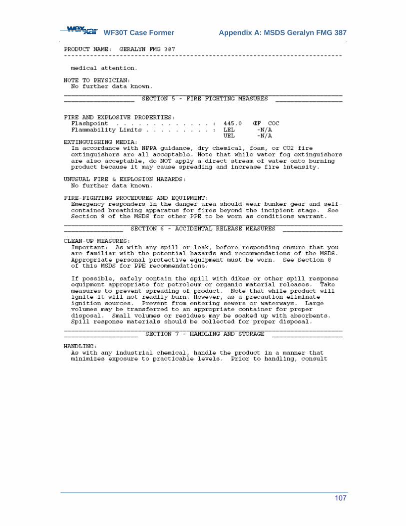
WF30T Case Former Appendix A: MSDS Geralyn FMG 387
107
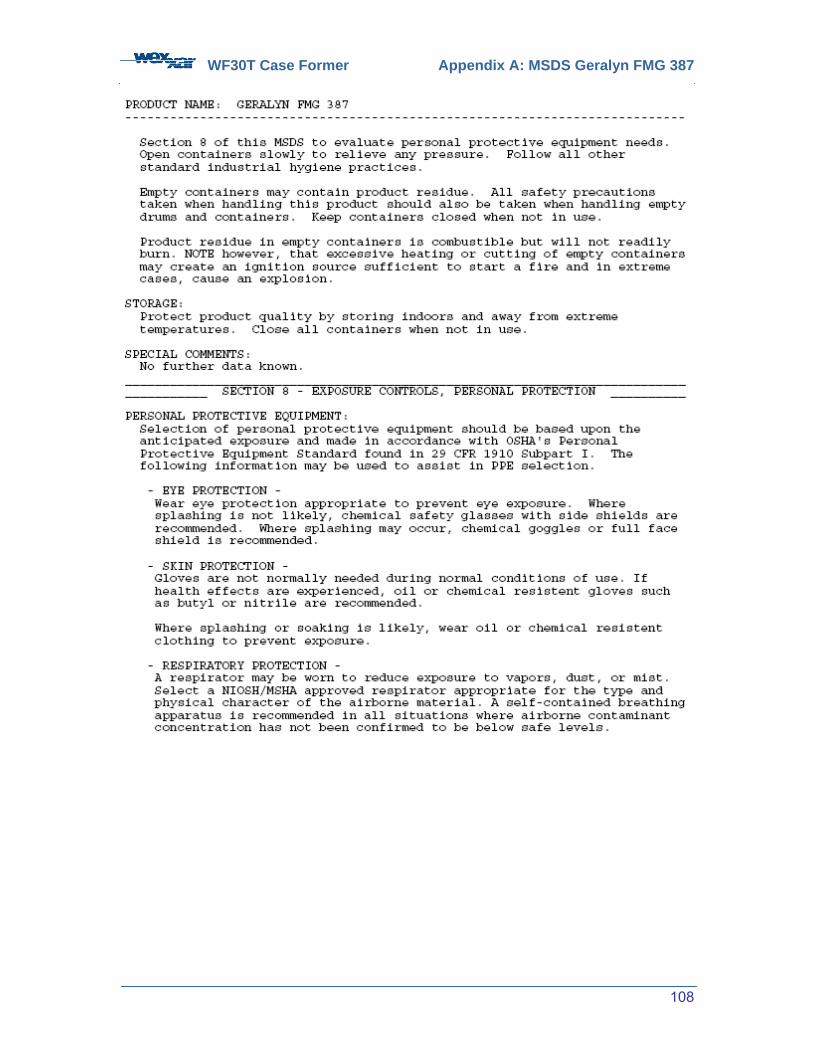
WF30T Case Former Appendix A: MSDS Geralyn FMG 387
108
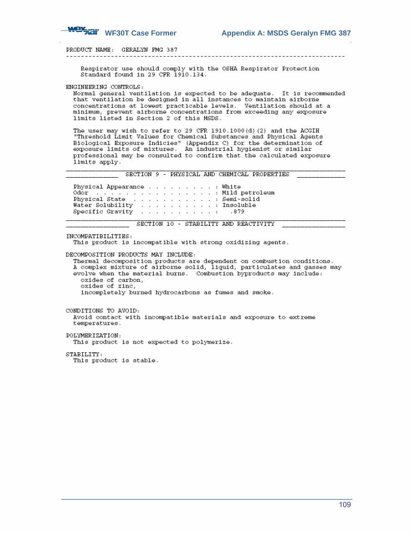
WF30T Case Former Appendix A: MSDS Geralyn FMG 387
109

WF30T Case Former Appendix A: MSDS Geralyn FMG 387
110

WF30T Case Former Appendix A: MSDS Geralyn FMG 387
111

WF-10T Case Former Appendix B: Keystone Nevastane HT-2
112
APPENDIX B Material Safety Data Sheets: Keystone Lubricants – Nevastane HT-2
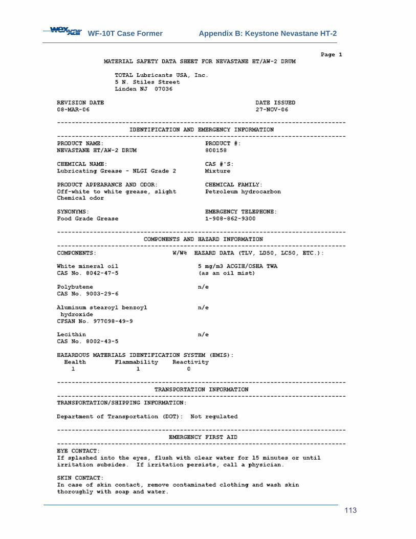
WF-10T Case Former Appendix B: Keystone Nevastane HT-2
113
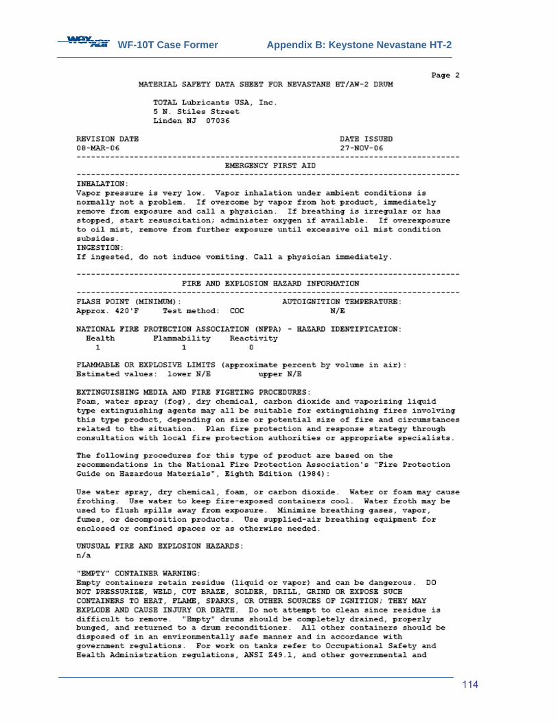
WF-10T Case Former Appendix B: Keystone Nevastane HT-2
114

WF-10T Case Former Appendix B: Keystone Nevastane HT-2
115

WF-10T Case Former Appendix B: Keystone Nevastane HT-2
116
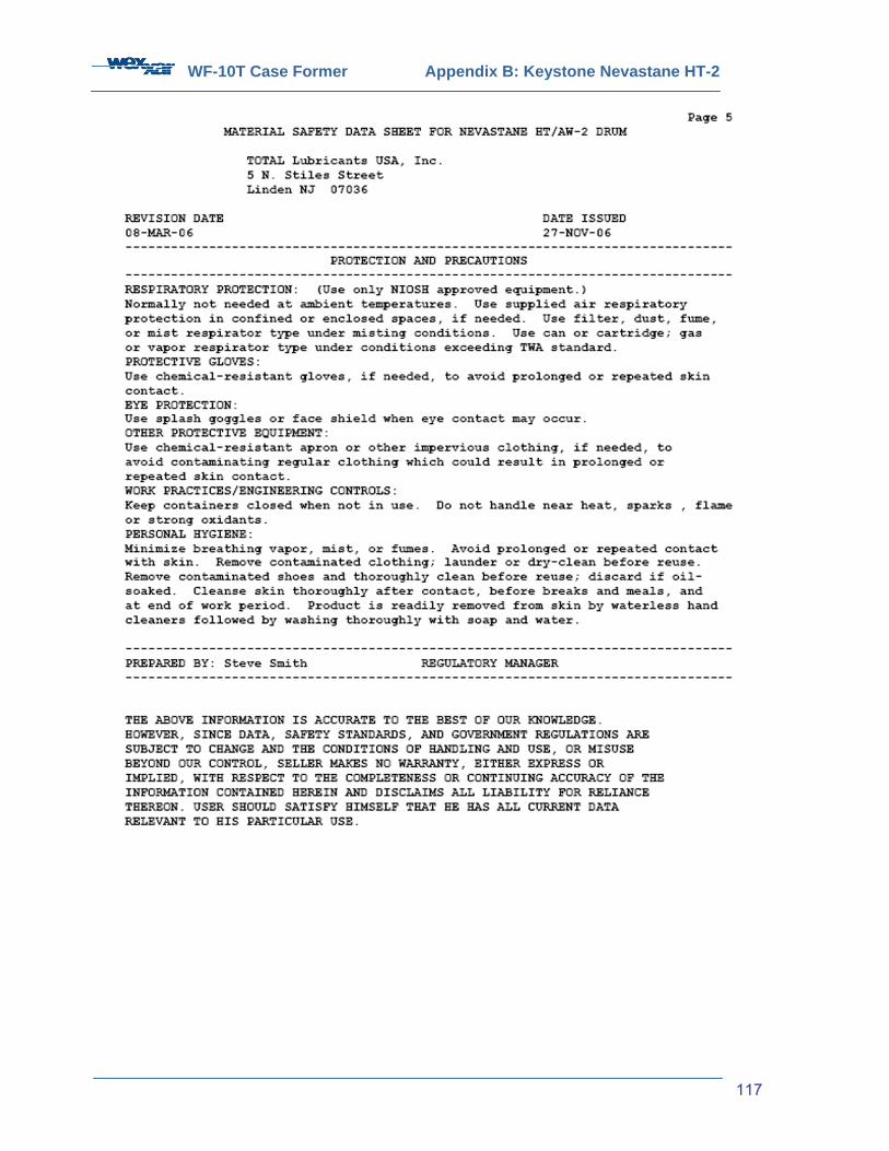
WF-10T Case Former Appendix B: Keystone Nevastane HT-2
117