Summary of the workshop on multi-paradigm modeling: concepts and tools
From Design Concepts toDesign DescriptionsSotirios D. Kotsopoulos
335issue 03, volume 06international journal of architectural computing

From Design Concepts to Design DescriptionsSotirios D. Kotsopoulos
The paper examines the process of articulation anddevelopment of design concepts from a computationalstandpoint.The context of the research is thearchitectural studio and the process of designing fromscratch.The scope of the research is educational.Shape grammar formalism is used in a retrospectiveanalysis, to show how the concept of “porosity” wasused by architect Steven Holl and his team indesigning Simmons Hall, a 350-unit student residence,at MIT.
336
1. INTRODUCTION
“I depend entirely on concept diagrams, I consider them my secretweapon.They allow me to move afresh from one project to the next,from one site to the next.” [1]
Architect Steven Holl acknowledges his dependence on open-endedconceptual frames rather than on the existing building morphologies andtypologies. Holl disregards any fixed architectural vocabulary in favor of an“initial concept” capturing the essence of design possibilities that heconsiders unique for each project. For Holl, a concept more than just averbally expressed idea sets a “manifold relation” among the site, thegeometry, the program, the circumstance, the materials etc.
For many architects and designers, design concepts play a key role in thedevelopment of innovative design solutions. Even though designers do notmake a sharp distinction between the process of production and theprocess of interpretation of designs, an “intended” interpretation usuallyguides their actions in the studio. Early conceptual schemes are used toframe a particular design approach. In this paper, a method for generatingarchitectural form from design concepts is suggested.The method is basedon visual productions rules that generate design descriptions.Theproduction rules are expressed by means of shape grammar formalism.Thepresented paradigm is a retrospective demonstration of how porosity, aconcept transferred from medicine, biology and organic chemistry, was usedby architect Holl and his team in designing Simmons Hall, a 350-unit studentresidence, at the Massachusetts Institute of Technology.
The novel aspect of the paper is to show how a design concept can betreated by formal-generative means to produce design descriptions “fromscratch”. Background assumption and motivation of this study was that adesign concept is at its root a course of action meant to be performed bythe designers in the studio. Setting a design concept is equal todistinguishing the identity of particular design events. It is proposed thatthere is no more to framing a design concept than there is to grasping anumber of grammatical transformation rules. But, setting forth a designconcept is not equal to laying down instructions. It depends on “framingideas” of particular design activities and coping with spatial relations andtheir features.The paper shows that the productive contribution of earlyconceptual schemes in design can be enhanced by formal-generative means,in three ways: First, by making their description explicit; second, by leadingto the implementation of computational devices with strong generativecapacity; and third, by making them available for future reference.Thedescriptive task involves the mapping of the actions implied by a designconcept with the aid of rule schemata and rules.The productive taskinvolves the implementation of the rules in shape grammars and computerprograms.The reference task involves the assemblage of customcomputational tools and data structures that can be retrieved by future
337From Design Concepts to Design Descriptions

users. In extension of the above, it is proposed that design concepts canmediate between intuition and computation.Against the temptation of“developing a computer program first, and then see what happens”, aconceptual scheme assists in framing patterns of activity within a specificcontext.This is important in architectural design, where the distinctionbetween abstract problem solving methods and case-specific techniquescannot be as concrete as in other branches of engineering. Intuitions aboutassociations with often ill-defined, but familiar, concepts have to beconsulted frequently to assure that one is not dealing with fake issues.
2. BACKGROUND
Engineers, design theorists, and researchers of Artificial Intelligence havethoroughly examined the use of concepts in design. David Ullman, forexample, considers the formation of design concepts in the context ofmechanical engineering, in designing or re-designing devices with specificfunctionality. In recent years, analogous views became increasingly popularamong architects and designers. Ullman [2] defines a design concept as “anidea that is sufficiently developed to evaluate the principles that govern itsbehavior”.A key feature of Ullman’s approach is the generation andevaluation of multiple concepts for the same design task. Conceptgeneration involves two steps: a) functional decomposition, and b) conceptgeneration from functions. Functional decomposition involves breakingdown the needed function of a device, as finely as possible and with as fewassumptions about form as possible. Concept generation happens throughthe listing of several conceptual ideas for each function. Conceptual ideasderive from the designer’s own expertise, enhanced through pattern search,reference books, brainstorming etc.
Donald Schön [3] proposes the displacement of concepts as a unifyingprinciple in terms of which innovation in technical discovery and in theoriesmay be explained as manifestation of a single process. Schön’s view evolvesin relation to metaphor, analogy and comparison.The displacement ofconcepts has a “radical” character, in that old concepts can be used as aprojective model for new situations and a “conservative” character, in thatold assumptions may be transposed in a covert or non-critical way to freshcontexts. Schön [4] approaches design as a situated activity in whichdesigners seek to comprehend and “frame” a problem. In their effort, thedesigners initiate a reflective conversation with the problem, involving actionand reflection on the consequences.This reflective, bi-directional process,leads to the formation of new meanings and to the reframing of theproblems.
John Gero examines the formation of design concepts in the making ofdesign descriptions by means of computational models developed inArtificial Intelligence. Gero [5] uses implemented examples drawn from thegenetic engineering of evolutionary systems to show that the formation of
338 Sotirios D. Kotsopoulos

design concepts is based on the emergence of patterns in the availabledesign representations.A key feature of Gero’s approach is that theemergent patterns form the basis of new concepts: they are memorized tobecome a repertoire of known patterns that remain available for future use.
Along the same lines, Suwa, Gero, and Purcell [6] examine how earlysketches are essential for the formation of design concepts.The researchersuse protocol analysis in studying the design process of a practicing architect,to show that the early sketches serve as a record and as a provider ofvisual cues for association of non-visual information, but also as a physicalsetting in which design thoughts are constructed.The authors propose thatthe inspection of early sketches forms the basis for the invention of noveldesign issues. New concepts emerge out of inspection of the existinginformation, or as a result of action upon previously produced visualmaterial. Novel design issues may include design goals derived from explicitknowledge, extensions of previous goals, goals aiming to resolve specificconflicts, or unsupported goals.
Like in Schön [3], [4], Gero [5], and Suwa, Gero and Purcell [6] thepresent study refers to creative design from “scratch”, as opposed to re-design.The focus is on architectural design, as opposed to design inmechanical engineering. Unlike Gero [5] and, Suwa, Gero and Purcell [6] thisstudy is based on the observation that architects introduce concepts thatdo not necessarily emerge out of the existing design representations. Onthe contrary, they can be imports from domains foreign to design, likebiology, chemistry, physics, mathematics, music, etc. Just as proposed inSchön [3], these concepts are transposed in a non-critical way to designcontexts, with a view to focus the designers’ attention on particular featuresof a problem and to propagate a course of action. In this paper, shapeformalism is used to model this action.
Shape formalism, as defined in Stiny and Gipps [7] and developed inconsecutive papers, extends the formalism of production systems andgenerative grammars in modeling the interaction of spatial forms. Points,lines, planes and solids are classified in sets according to their spatialdimension, they are ordered with the part relation (≤) and they areorganized into shape algebras, where operations like addition, subtractionand product can be used to perform spatial calculations. For example, theshape algebra U12 contains 1-dimensional elements – lines – that aremanipulated on the 2-dimensional plane.
Accordingly, the shape algebra U13 contains lines that are manipulated in the3-dimensional space and the shape algebra U33 contains solids that are
� Figure 1. Examples of forms in the
algebra U12
339From Design Concepts to Design Descriptions
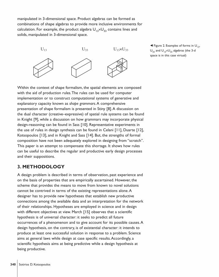
manipulated in 3-dimensional space. Product algebras can be formed ascombinations of shape algebras to provide more inclusive environments forcalculation. For example, the product algebra U13×U33 contains lines andsolids, manipulated in 3-dimensional space.
Within the context of shape formalism, the spatial elements are composedwith the aid of production rules.The rules can be used for computerimplementation or to construct computational systems of generative andexplanatory capacity known as shape grammars.A comprehensivepresentation of shape formalism is presented in Stiny [8].A discussion onthe dual character (creative–expressive) of spatial rule systems can be foundin Knight [9], while a discussion on how grammars may incorporate physicaldesign-reasoning can be found in Sass [10]. Representative experiments inthe use of rules in design synthesis can be found in Celani [11], Duarte [12],Kotsopoulos [13], and in Knight and Sass [14]. But, the strengths of formalcomposition have not been adequately explored in designing from “scratch”.This paper is an attempt to compensate this shortage. It shows how rulescan be useful to describe the regular and productive early design processesand their suppositions.
3. METHODOLOGY
A design problem is described in terms of observation, past experience andon the basis of properties that are empirically ascertained. However, thescheme that provides the means to move from known to novel solutionscannot be contrived in terms of the existing representations alone.Adesigner has to provide new hypotheses that establish new productiveconnections among the available data and an interpretation for the networkof their relationships. Hypotheses are employed in science and in designwith different objectives at view. March [15] observes that a scientifichypothesis is of universal character: it seeks to predict all futureoccurrences of a phenomenon and to give account for its possible causes.Adesign hypothesis, on the contrary, is of existential character: it intends toproduce at least one successful solution in response to a problem. Scienceaims at general laws while design at case specific results.Accordingly, ascientific hypothesis aims at being predictive while a design hypothesis atbeing productive.
� Figure 2. Examples of forms in U13,
U33 and U13×U33 algebras (the 3-d
space is in this case virtual)
340 Sotirios D. Kotsopoulos
Hypotheses are associated with the introduction of concepts.A conceptsingles out a property, a relation, or an action by setting out a name, or ascheme. For example:
Pore = minute opening.A concept can be introduced contextually by a list of synonyms that explainit.The explanation becomes in this case a creative medium as it may suggestnew meanings. Design concepts are introduced contextually and in parallelto a course of action that is organized and explained in terms of them.Themeaning of a design concept becomes its use: interpreting the output of theaction confers meaning on the concept.
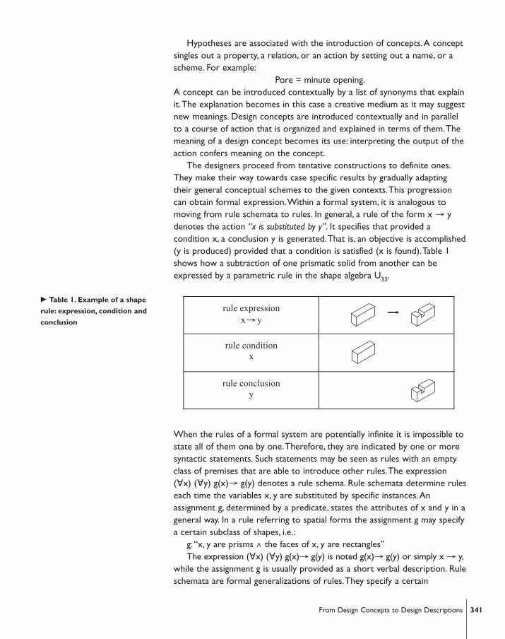
The designers proceed from tentative constructions to definite ones.They make their way towards case specific results by gradually adaptingtheir general conceptual schemes to the given contexts.This progressioncan obtain formal expression.Within a formal system, it is analogous tomoving from rule schemata to rules. In general, a rule of the form x → ydenotes the action “x is substituted by y”. It specifies that provided acondition x, a conclusion y is generated.That is, an objective is accomplished(y is produced) provided that a condition is satisfied (x is found).Table 1shows how a subtraction of one prismatic solid from another can beexpressed by a parametric rule in the shape algebra U33.
When the rules of a formal system are potentially infinite it is impossible tostate all of them one by one.Therefore, they are indicated by one or moresyntactic statements. Such statements may be seen as rules with an emptyclass of premises that are able to introduce other rules.The expression(∀x) (∀y) g(x)→ g(y) denotes a rule schema. Rule schemata determine ruleseach time the variables x, y are substituted by specific instances.Anassignment g, determined by a predicate, states the attributes of x and y in ageneral way. In a rule referring to spatial forms the assignment g may specifya certain subclass of shapes, i.e.:
g:“x, y are prisms ∧ the faces of x, y are rectangles” The expression (∀x) (∀y) g(x)→ g(y) is noted g(x)→ g(y) or simply x → y,
while the assignment g is usually provided as a short verbal description. Ruleschemata are formal generalizations of rules.They specify a certain
rule expression x→ y
rule condition x
rule conclusion y
� Table 1. Example of a shape
rule: expression, condition and
conclusion
341From Design Concepts to Design Descriptions

treatment for an entire family of forms, instead of just for specific instances.For example, the shape rule illustrated in Table 1 becomes the expression ofa rule schema after providing the above mentioned assignment g, whichspecifies a general family of shapes that this rule can apply.
Two are the key aspects of its application,“recognition” and“modification”.As shown in Stiny [8], a shape rule schema applies on adescription C in two steps: First, a transformation t “recognizes” some partof C geometrically similar to the shape g(x). Second, the sametransformation t is used to “modify” C: it substitutes t(g(x)) with t(g(y)).Concisely: C' = [C – t(g(x))] + t(g(y)).
Figure 4 presents a sequence of shapes produced after applying the ruleschema of the Table 1, on an initial shape C, in the shape algebra U33. Such asequence of shapes is called a derivation.
When rules are used in the execution of predetermined tasks they arereduced to “instructions”. But, in the context of a non-deterministic designprocess rule setting is a creative activity. Setting rules is equal to identifyingparticular kinds of action, usually of repetitive character.This makes rulesideal for the framing of design concepts.There is no more to framing adesign concept than there is to grasping a number of grammatical rules.Nevertheless, in the context of a non-deterministic design processpossessing a number of rules is not equal to obeying to instructions. Itrequires dealing with relations and features. Lacking the ability to makerelational judgments prevents one from understanding how something canbe “part of” something else and makes the grasping of a rule, or a concept,impossible. First,“awareness” of what stands as a complete x – that is, whatwe see on the left hand side of the rule, is required. Second,“judgment”, theability to use one’s awareness of x, to distinguish a location to “match” x ina display at a given time, is necessary. Since different matching locations areusually presented, judgment is required in distinguishing where and when
C
⇒ ⇒ ⇒ ⇒ …
C t(g(x))<C C-t(g(x)) � Figure 3. Example of applying the
rule of Table 1, in the shape algebra
U33
� Figure 4. Example of a possible
derivation in the shape algebra U33
342 Sotirios D. Kotsopoulos

t(x) becomes part of C in an evolving design process.Third, coping with therecognition of matching locations that have the feature to be unfinished orincomplete xs – sets of maximal elements that can be embedded on it,without forming a complete x – is necessary.The recognition of incompletexs emphasizes the distinction of a “characteristic pattern” from an arbitraryone.While any arbitrary x allows the recognition of individual instances t(x)in a description, an arbitrary x does not prompt the viewer to distinguishincomplete xs, which are not presented as wholes. On the contrary, acharacteristic pattern – that is, a pattern singled out by name – providesbetter basis for the distinction of locations of incomplete matching.Thisobservation allows for the distinction of places that have the feature to beparts of a characteristic pattern, and those which do not.Accordingly, a ruleschema provides better means for treating incomplete xs, since it refers toa family of x-like forms rather than a specific x instance.
4.THE SIMMONS HALL PARADIGM
The Simmons Hall student dormitory is part of a strip of future buildingsforming the Vassar Street edge along the Briggs Athletic Field at MIT, inCambridge, Massachusetts.This strip of buildings was seen by Holl’s team asan opportunity to propose a new type of student living. Instead of thetypical brick urban wall the strip was envisioned as a “porous membrane”including a number of individual dormitories, which function as theboundary of the residential city fabric.The dormitories were envisioned tobe “permeable” to allow maximum visual penetration.At the same time,each dormitory was designed as “an individual house with a particularidentity” [17]. Simmons Hall is a 350 bed residence, designed as a verticalslice of a city, 10 stories high and 382 feet long, including facilities such as a125-seat theater and a night café.The corridors connecting the rooms weremetaphorically approached by the designers as “streets”, operating as publicplaces. In designing Simmons Hall, the features of “pores” and porousmaterials were approached as tectonic possibilities.The porosity conceptformed a “porous” morphology through the application of a series ofoperations.Accordingly, the overall building mass has five large scalerecesses, while a system of vertical sponge-form cavities creates verticalporosity, allowing natural light and air to circulate in the interior.Thebuilding facades are composed by 5538 operable windows.
� Figure 5. Erecting Simmons Hall
student dormitory
343From Design Concepts to Design Descriptions
The discussion of the Simmons Hall paradigm emerged out of threeinterviews with the project architect Timothy Bade, two meetings with thearchitect Steven Holl and a public lecture that Holl gave at ColumbiaUniversity, in February 12, 2003.The illustrations include descriptions suchas sketches, working drawings and models from the various stages of thedesign process.The presented visual material was also exhibited at theopening of Simmons Hall, in February 2003.
In the next section formal-generative methods are outlined that depicthow the concept of “porosity” was transposed in a tectonic-urban contextto guide the production of a sponge-like morphology for Simmons Hall.Parametric rule schemata are used to map the patterns of development inthe working drawings and the models.The analysis is retrospective.The ruleschemata aim at framing the design concept rather than describing theactual studio techniques.The adopted approach is favored for itsexplanatory and productive merits: it makes the design concept transparentby establishing links between “words” and “actions”, and it provides a basisfor further computational exploration.
4.1. Porosity
Pore (from Greek πóρoζ) means “a minute opening”. Porosity or “the stateof being porous” in medicine and the study of plants and animals indicatesthe existence of small openings. In biology and in organic chemistry porosityis defined as:“the attribute of an organic body to have a large number ofsmall openings and passages that allow matter to pass through”.The forms,the sizes and the distribution of pores are arbitrary.Their functionality isassociated with circulation and filtration with respect to the externalenvironment.The concept of porosity was transposed in a tectonic/urbancontext to guide the production of a porous morphology for Simmons Hall.This brings into mind the principle of “concept displacement” as describedin Schön [3]. Holl [16] mentions the influence of Marleau-Ponty stating thatenvironments include patterns or “lines of force” and possibly meanings.Holl’s conceptual approach to design is addressed in his public talks [17]:“Within the phenomena of experience in a build construction, theorganizing idea is a hidden thread connecting dispersed parts with exactintention”. More specifically, Holl [16] phrased the working hypothesis forSimmons Hall as follows:“What if one aspect of a site – porosity – becomesa concept? Porosity can be a new type of being…We hope to develop thepossibility of a collection of things held together in a new way”.Table 2presents the synonyms used by Holl’s team in organizing a contextualdefinition for porosity.
344 Sotirios D. Kotsopoulos

p o r o s i t y
porous, permeable honeycomb
screen, net riddle, sponge
pore opening, hole
aperture, passageway cribiformity
sieve-like, sieve pervious
unrestricted
The porosity concept was part of a wider hypothesis, the “permeabilityhypothesis”, conjecturing that a porous morphology would have positiveeffects at an urban and building scale: better air and light circulation, betteraccessibility and visibility at an urban scale, and better communicationbetween interior and exterior at a building scale.The permeabilityhypothesis helped the design team to establish novel relationships amongthe elements of the building program. Holl [16] recalls: “Our project beganby rejecting an urban plan that called for a wall of brick buildings of aparticular ‘Boston type’. Instead, we argued for urban porosity”.At the earlystages, the design team developed a series of design alternatives. Contraryto what is suggested in Ullman [2] – multiple concept generation andevaluation – each of the early case-study-designs developed by Holl’s teamwas a demonstration of implementing variations of the same conceptualscheme of “porosity”.The schematic variations included “horizontal”,“vertical”,“diagonal” and “overall” porosity alternatives, characterized byvarious types and degrees of “permeability”.
Some early schematic arrangements appear in Figure 6.
After many of the schematic proposals were rejected by the buildingauthority, the design team shifted to the “sponge” example to implementwhat was labeled as “overall urban porosity”. Overall porosity was based ontwo general schemes: the abstract, recursive scheme of the Menger spongeand the organic scheme of the natural sponge (Figure 7, up-left).A tectonicversion of porosity was realized by bringing in contact as much of thebuilding’s interior with the exterior as possible, by creating openings,internal channels and cavities.This was accomplished in four ways: first, bycreating large-scale recesses of building mass; second, by creatingprotrusions of building mass; third, by distributing multiple windows ofvarious size on the elevations; and fourth, by distributing a number of free-form vertical cavities, penetrating the building from top to bottom.The four
� Table 2: Contextual definition
of the design concept of porosity
by Steven Holl Architects, New
York, NY
� Figure 6. Building types of
permeability. Steven Holl Architects,
New York, NY
345From Design Concepts to Design Descriptions

operations guided the production of design descriptions.The results weredepicted in sketches and models, a representative fraction of which appearsin Figure 7.
The four design operations correspond to four parametric rule schemata A,B, Γ, ∆.The rule schemata A, B operate in the algebra U33, which includessolids manipulated in 3-dimensional space.The rule schemata Γ, ∆ operatein the product U13×U33, which includes lines and solids manipulated in 3-dimensional space.The four design operations, described by the ruleschemata, are:A) large-scale prismatic voids of building mass are producedthrough subtraction, B) large-scale protrusions are produced throughdivision and translation of half of the building along its longitudinal axis, Γ)sieve-like windows are applied on the façade panels, through subtraction, ∆)vertical free, sponge like forms are embedded in the orthogonal buildinggrid.
Illustrations of the four parametric rule schemata appear in Table 3.
Rule schema A
The first operation allows the creation of prismatic recesses of buildingmass.These are described by the design team as “large scale openings,
porosity
Rule schema A Rule schema B
Rule schema Γ Rule schema ∆
� Figure 7. Overall porosity. Early
design schemes. Steven Holl
Architects, New York, NY
� Table 3:The parametric rule
schemata A, B, ΓΓ, ∆∆
346 Sotirios D. Kotsopoulos

corresponding to main entrances, view corridors, and the main outdooractivity terraces of the dormitory”.The operation exposes more buildingsurfaces towards the exterior and forms terraces.A rule schema depicts theoperation: solids are subtracted from a larger solid, corresponding to theoverall building mass.The solids are parametric oblongs and prisms.Theapplication of rule schema A affects the form and the available square-footage of the building.The parametric rule schema A is repetitive: it appliesseveral times under translation, rotation, reflection and scaling.
Rule Schema B
The second operation divides the building mass in two halves, and translatesone along its longitudinal axis.The specific transformation was labeled byHoll’s team as “diagonal porosity”.The corresponding rule schema divides aparametric solid into two equal parametric solids and translates one halfalong its long axis, for some distance x.The result from the application ofthis operation is that more of the building’s interior is exposed towards theexterior.The application of rule schema B affects the building’s form withoutaltering its square-footage.The parametric rule schema B is non repetitive: itapplies only once under a single transformation, at the early stages of thedesign process.
Rule Schema Γ
A third operation is used for the treatment of the elevations, to distributewindows of various size.The operation has its conceptual basis inmathematics and the concept of the Sierpinski carpet, or its 3-dimentionalextension the Menger sponge (Figure 7, up).The Sierpinski carpet is a 2-dimentional fractal constructed as follows: a) a plane, square in shape, isdivided in 3 × 3 = 9 congruent squares, b) the center square is removed.This treatment applies recursively to the remaining 8 squares and it maycontinue indefinitely.A 3-dimentional version of the Sierpinski carpet,involving cubes instead of squares, forms the Menger sponge. Illustrations ofLevel 1, 2 and 3 Sierpinski carpets, appear in Figure 8.
In the context of designing Simmons Hall, rule schema Γ applies recursivelyon a square façade panel to produce multiple openings, through subtraction.Rule schema Γ introduces a mathematical expression of a “sponge”, which isbased on the recursive construction of the Sierpinski carpet.Thisconstruction also responds to a need for better air and light circulation,
� Figure 8.The second, third and
fourth shapes from the left, depict a
Level 1, 2 and 3 Sierpinski carpet
347From Design Concepts to Design Descriptions

which was a core design concern in designing Simmons Hall.The applicationof rule schema Γ, affects the facades without altering the square-footage ofthe building.The parametric rule schema Γ, applies several times undertranslation and scaling.
Rule Schema ∆
A fourth operation, introduced by Holl’s team, was named “verticalporosity”.Vertical, sponge-like openings penetrate the building from top tobottom, allowing circulation among the different levels.These aremetaphorically described by the design team as “large dynamicopenings…the lungs of the building, bringing natural light down and movingair up through the section”.Vertical porosity is depicted here by aparametric rule schema that embeds sponge-like forms within the grid ofany two consecutive slabs.The rule schema ∆ introduces free organic forms,which serve as a reminiscence of the natural sponge, as opposed to themore abstract, recursive formulations of the Menger sponge (Figure 7, up).The application of the rule schema ∆ affects the building’s available area andvolume, and the interior space.The parametric rule schema ∆ appliesseveral times under translation.
Derivation
A derivation involving the applications of the parametric rule schemata Aand B appears in Table 4.The derivation is presented in three columns, eachincluding six steps, performed in parallel.The main derivation appears on theleft column involving a series of subtractions among solids.The subtractionsare performed in the algebra U33, which contains solids manipulated in 3-dimensional space.At the top of the left column, the initial shape is aparametric solid representing the overall building mass. For brevity, the ruleschema A applies twice at the first three steps of the derivation.At eachstep, the left column shows the produced shape: C' = [C – t(x)] + t(y).Thecenter column, presents the subtracted solids t(x) in the product algebraU13×U33, which contains lines and solids manipulated in 3-dimensional spaceThe right column, presents the sum of the subtracted solids at each stepΣ[t(x)].The outline of the building is also presented with lines (for visualreference to the overall building mass).
A derivation involving the application of rule schema ∆ appears in Table 5.The derivation is presented in two columns, top to bottom, starting fromthe left. It shows how the vertical, sponge-like cavities are embedded on the3-dimensional orthogonal building grid. For brevity, the rule schema ∆applies more than once at all the twelve steps.The product algebra U13×U33,which contains lines and solids manipulated in 3-dimensional space, is usedin this derivation.
348 Sotirios D. Kotsopoulos

[C – t (x)] + t(y) t(x) ∋ [t(x)]
⇓
⇓
⇓
⇓
⇓
A, A
A, A
A, A
A
B
� Table 4. Derivation of porosity
after rule schemata A and B.
349From Design Concepts to Design Descriptions

� Table 5. Derivation of porosity
after rule schema ∆∆.
350 Sotirios D. Kotsopoulos
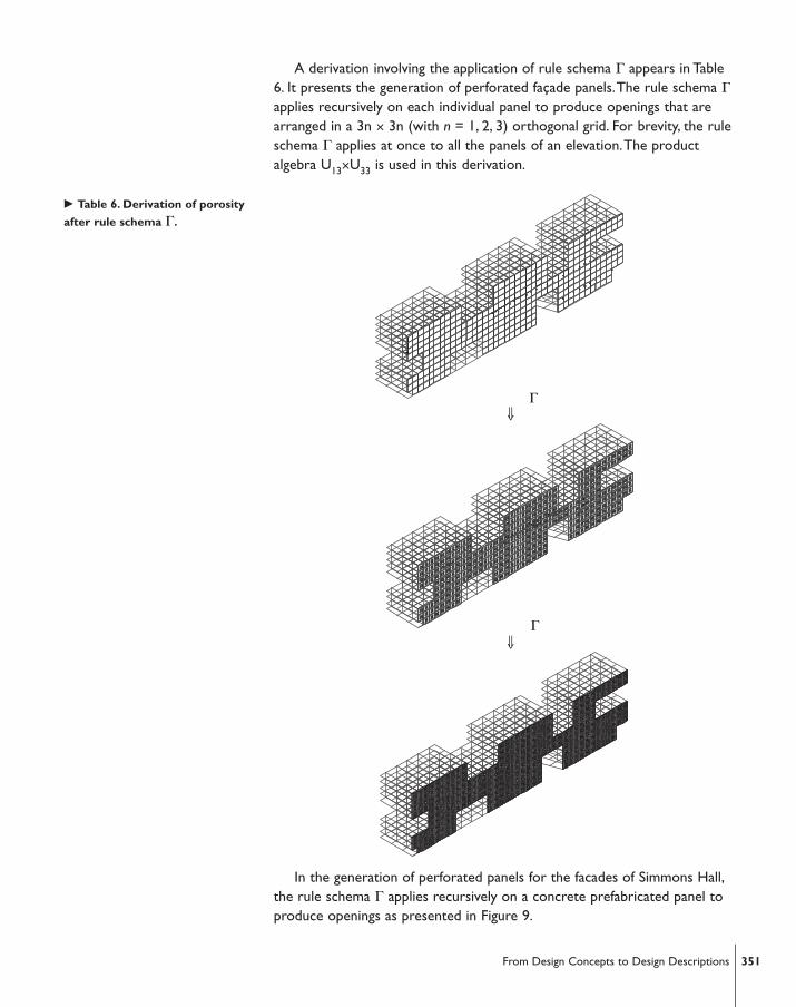
A derivation involving the application of rule schema Γ appears in Table6. It presents the generation of perforated façade panels.The rule schema Γapplies recursively on each individual panel to produce openings that arearranged in a 3n × 3n (with n = 1, 2, 3) orthogonal grid. For brevity, the ruleschema Γ applies at once to all the panels of an elevation.The productalgebra U13×U33 is used in this derivation.
In the generation of perforated panels for the facades of Simmons Hall,the rule schema Γ applies recursively on a concrete prefabricated panel toproduce openings as presented in Figure 9.
� Table 6. Derivation of porosity
after rule schema Γ.
351From Design Concepts to Design Descriptions
⇓
⇓
Γ
Γ

Façade configurations involving panels like the above are depicted in earlysketches of Simmons Hall. However, quickly the abstract concept ofrecursion gave its place to more tectonic considerations. In Simmons Hall,the exterior concrete wall serves as the main load bearing grid of thebuilding.This dictates the standardization of the openings.The emergentcomponent was the “perfcon”, a structure described by Holl’s team as “adesign allowing maximum flexibility and interaction”.The building facadesare designed to have a total of 5538 windows nested in a uniform concreteprefabricated wall 18'' thick that fuses windows and structure. Early studiesdepicting the two design approaches appear in Figure10.
The generation of a typical “perfcon” panel is depicted in Figure 11 by a ruleof the form x→y.
A typical “perfcon” panel has three 2' × 2' windows in height and six inwidth (3 × 6). Each individual room has nine windows in total (3 × 3).Therefore, typically, a perforated panel covers two adjacent rooms.However, there are 3 × 5 panels and a small number of 3 × 4, 3 × 3, 3 × 2,3 × 1 and 3 × 7 panels.A schematic presentation of the full panel vocabularyappears in Figure 12.
⇒ ⇒
� Figure 9. Generation of façade
panels, after recursive application of
rule schema Γ
� Figure 10. Early studies of Simmons
Hall, by Steven Holl Architects, New
York, NY
� Figure 11. Formation of a “perfcon”
panel in the product algebra U13×U33.
352 Sotirios D. Kotsopoulos
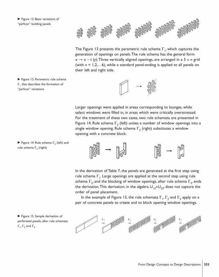
The Figure 13 presents the parametric rule schema Γ1, which captures thegeneration of openings on panels.The rule schema has the general formx → x – t (y).Three vertically aligned openings, are arranged in a 3 × n grid(with n = 1,2,…6), while a standard panel-ending is applied to all panels ontheir left and right side.
Larger openings were applied in areas corresponding to lounges, whileselect windows were filled in, in areas which were critically overstressed.For the treatment of these two cases, two rule schemata are presented inFigure 14. Rule schema Γ2 (left) unites a number of window openings into asingle window opening. Rule schema Γ3 (right) substitutes a windowopening with a concrete block.
In the derivation of Table 7, the panels are generated at the first step usingrule schema Γ1. Large openings are applied at the second step using ruleschema Γ2, and the blocking of window openings, after rule schema Γ3, endsthe derivation.This derivation, in the algebra U13×U33, does not capture theorder of panel placement.
In the example of Figure 15, the rule schemata Γ1, Γ2 and Γ3 apply on apair of concrete panels to create and to block opening window openings.
Γ1
⇒Γ1
⇒Γ2
⇒Γ3
⇒
� Figure 12. Basic variations of
“perfcon” building panels
� Figure 15. Sample derivation of
perforated panels, after rule schemata
Γ1, Γ2 and Γ3
� Figure 14. Rule schema Γ2 (left) and
rule schema Γ3 (right)
� Figure 13. Parametric rule schema
Γ1 that describes the formation of
“perfcon” variations
353From Design Concepts to Design Descriptions

� Table 7. Derivation of porosity
after rule schema ΓΓ.
354 Sotirios D. Kotsopoulos
⇓ Γ1
⇓ Γ2
⇓ Γ3

The “perfcon” panels were used as building blocks in the erection of thefacades: 291 panels were used in total, with approximately 11 panels erectedper day. Due to the structural importance of the façade walls, the actualplacement of the different panel types, and the number and size of theiropenings, were determined by structural and functional criteria. In acomputational simulation of the principles that guided the panel placement,the discrimination of the various panel types can be expressed with the aid oflabels, while the act of panel placement can be controlled with substitutionrules. For example, at each floor: the typical 3 × 6 panels may get substitutedfirst, the 3 × 5 panels next, the 3 × 4 next, etc., and the corner panels last. Ofcourse, the determination of the position of each panel on a façade was theresult of calculations that occurred in a much later stage of the designprocess.Accordingly, the formation of the appropriate computational rules,while taking into account these calculations, requires a level of detail that goesbeyond the objectives of this discussion.An exposition of the necessaryconstruction rules may follow in a future presentation.
4.2. Discussion
Evidence of the application of the four parametric rule schemata A, B, Γ, ∆can be traced at the early design representations, such as sketches, physicalmodels and schematic illustrations, of Simmons Hall.A possibleretrospective illustration, emerging from the application of the porosityoperations appears in Figure 17.
� Figure 16. Placing the final piece
� Figure 17.A possible retrospective
illustration of Simmons Hall, after the
porosity operations
355From Design Concepts to Design Descriptions

A comparison among the early design descriptions and the actualSimmons Hall dormitory shows that some of the early conceptual schemeswere partially or totally abandoned in the process of implementation.Thebuilding deviates from the descriptions of the design intent. For example,the building recesses generated by the rule schema A were partiallyreversed.And the results of the application of rule schema B (diagonalporosity), were entirely eliminated during implementation. Several windowsgenerated by the rule schema Γ, were ultimately blocked by concreteblocks, due to structural or other requirements. For the same reason, theabstract concept of recursion was dropped rather early, and the intendedwindow variety on the facades, was restricted to a single standard window,with the exception of a limited number of larger openings. Further, theindented creation of multiple cavities, via rule schema ∆ (vertical porosity)was hindered: only three vertical cavities were distributed to the overallbuilding mass. Last, due to the fire-safety regulations, the vertical cavitieswere not allowed to penetrate the building from top to bottom, thus failingto fulfill their original functional purpose of vertical circulation.Asummarizing visual comparison among the early descriptions of intents andthe finally implemented building configurations is presented in Table 8.
However, it is still accurate to say that the implementation of Simmons Hallfalls within the design space that was determined by the concept ofporosity.The final design can still be produced by instances of theparametric rule schemata A, Γ, ∆.The rule schema A introduces “pores” at alarger scale: that of the building mass.The rule schema Γ introduces “pores”at a smaller scale: that of the façade panel.And, the rule schema ∆introduces organic cavities affecting both scales: the building’s mass and theinterior space.The productive contribution of the “permeability” hypothesisand of the “porosity” concept was to focus the designers’ attention on
� Table 8. Intended (up) and actual
(down) implementation of Simmons
Hall
356 Sotirios D. Kotsopoulos
particular features of the problem, and to provide a basis for the building ofa problem space containing these features. Making novel associations andbuilding a non trivial problem representation is essential in the productionof novel solutions. It signifies what Holl describes as “remainingexperimental and open”. Rather than simply solving a given program, withinpredetermined confines, what the architect contributes to is the explorationof new hypotheses.Then, the actual process of “making” supports orinvalidates the hypothetical constructions. Holl [17] concludes:“By making,we realize that the idea is only a seed for extension in phenomena.Experience becomes a kind of reasoning distinct to the making ofarchitecture.Whether reflecting on the unity of concept and experience orthe intertwining of idea and phenomena, the hope is to unite intellect andfeeling, precision with soul”.
5. CONCLUSION
For many architects and designers, the ability to diagnose problems and toformulate productive hypotheses plays a key role in the development ofinnovative design solutions in the studio. Productive hypotheses allowdesigners to interpret the available design information in new ways.Theylead to the reframing of the problems and to the development of newmethods of production. Productive hypotheses are associated with theintroduction of concepts.The role of concepts in design is both descriptiveand productive.Verbal descriptions, keywords and conceptual schemes setforth at the early stages of the design process are economical and inclusivemeans to frame a general approach.
Background assumption and motivation of this study is that a designconcept is at its root a course of action meant to be performed by thedesigners in the studio. Design concepts are introduced contextually andjointly with a course of productive action that is organized and explained interms of them. Interpreting the output of the action confers meaning on theconcepts.This allows design concepts to evolve in parallel to designs. Designconcepts become explicit as designers adapt their general schemes to specificcontexts.This progression is analogous to moving from implicit principles toexplicit modes of action and their parameters. From a computationalstandpoint this is analogous to moving from rule schemata to rules.
Novel aspect of this paper was to show how computational rules can beuseful in describing the early productive design processes and theirsuppositions. It has presented a paradigm of how a design concept can betreated by formal-generative means in designing from scratch.And it hasshown that a design concept can be converted into a system of visual ruleschemata to generate design descriptions.The rule schemata wereexpressed by the means of shape grammar formalism.The paradigm was aretrospective analysis of how the concept of “porosity” was used byarchitect Holl and his team in designing the 350-unit student residence
357From Design Concepts to Design Descriptions

Simmons Hall, at MIT.It was also pointed out that design concepts do not necessarily emerge
out of the existing design representations, alone. But, they can be importsfrom domains foreign to design like biology, physics, mathematics, music,etc., which are transposed to design contexts, with a view to focus thedesigners’ attention on particular features of a problem and to propagate acertain course of productive action. Of course, the use of a word like“porosity” within a design context, does not guarantee the existence of astraightforward, formal way to identify the actions or the things it denotes,or to determine their features. However, the presented paradigmdemonstrated that when there is a recurring structure, or a “characteristicpattern”, a domain can be specified for which rules and meanings can beresolved.
Computational rule schemata were found ideal for the framing of designconcepts. It was proposed that there is no more to framing a designconcept than there is to setting a number of grammatical rules. Setting rulesis equal to identifying particular kinds of activity, usually of repetitivecharacter. It requires dealing with relations and features. Being unable tomake relational judgments prevents one from understanding how somethingcan be “part of” something else and makes the grasping of a rule, or aconcept, impossible. In applying a rule of the form x → y,“awareness” ofwhat stands as a complete x, and “judgment” to distinguish the appropriateplace and time to make x “part of” a description, are required.Acharacteristic pattern x, singled out by name, has the privilege to expand thedomain of the matching places, as it prompts the viewer to discoverincomplete xs. It provides the best basis for distinguishing places having thefeature to be parts of x.Accordingly, a rule schema provides better meansfor treating an x-like-family of forms, than a rule that treats only a specific x-instance.
In conclusion, the early exploratory stages of design can benefit by aformal-generative methodology in multiple ways.The description of designconcepts by rule schemata allows communicating abstract ideas withprecision without sacrificing generality.And the mapping of the actionsimplied by a concept to computational rules, allows the implementation ofdesign tools with strong generative capacity.The organization of sequencesof rules leads to the construction of grammars.And, the rule sequences canbe transferred to a programming language, as scripts, to become availablefor execution by digital machines.The encoding of design concepts intorules and custom computational tools makes the design process transparentand permits the future access and reuse of the design ideas.
In extension to the above, one may say that showing attention to theearly conceptual design schemes may provide a link between intuitive andcomputational design methodologies.This is important in architecturaldesign, where the distinction between general problem solving methods and
358 Sotirios D. Kotsopoulos
case-specific techniques is not firmly established.The development of customdigital design tools without an outline of formal or spatial expectations oftenabsorbs a lot of designers’ energy and attention and drives them away fromtheir intended spatial objectives.The ability to retain associations with earlyconceptual schemes assists in framing ideas of explicit patterns of activity andassures that one is not dealing with irrelevant issues.
Acknowledgements
I am indebted to the architects Steven Holl and Timothy Bade for allowingaccess to the design material of Simmons Hall. I am also indebted to Prof.Terry Knight and Prof. George Stiny, at MIT, for making useful suggestions.
References1. Holl, S., Idea and Phenomena, Lars Muller Publishers, 2002, 73
2. Ullman, D. G., The mechanical design process, McGraw Hill, 1992, 120-172
3. Schön, D.A., Displacement of Concepts,Tavistock Publications, London, 1963
4. Schön, D.A., Educating the Reflective Practitioner, Jossey-Bass, San Francisco,1990, 3-7
5. Gero, J. S., Concept formation in design, Knowledge-Based Systems, 1998, 10 (7-8),429-435
6. Suwa, M., Gero, J. S. and Purcell,T.,The role of sketches in early conceptual designprocesses, Proceedings of Twentieth Annual Meeting of the Cognitive Science Society,Lawrence Erlbaum, Hillsdale, New Jersey, 1998, 1043-1048.
7. Stiny, G. and Gips J., Shape Grammars and the generative specification in paintingand sculpture, Information Processing 71, ed. Freiman C.V., North Holland, 1972
8. Stiny, G., Shape:Talking about seeing and doing,The MIT Press, Massachusetts, 2006
9. Knight,T., Creativity. Rules, Proceedings of HI '05 Sixth International RoundtableConference on Computational and Cognitive Models of Creative Design, Heron Island,Australia, 2005.
10. Sass, L.,A Physical Design Grammar:A production system for layeredmanufacturing Automation in Construction, (forthcoming)
11. Celani, M. G. C., Beyond Analysis and Representation in CAD:A new computationalapproach to design education, PhD Thesis, Massachusetts Institute of Technology,2002.
12. Duarte J. P.,Towards the mass customization of housing: the grammar of Siza’shouses at Malagueira, Environment and Planning B: Planning and Design 32, 2005,347-380
13. Kotsopoulos, S. D., Constructing Design Concepts: A computational approach to thesynthesis of architectural form, PhD Thesis, Massachusetts Institute of Technology,2005.
14. Knight,T., and Sass L., Looks Count: Computing and Constructing Visually ExpressiveMass Customized Housing, Massachusetts Institute of Technology, (forthcoming)
15. March, L.,The logic of design and the question of value, in The Architecture ofForm, (March L., Ed) Cambridge University Press, 1976, 18
16. Holl, S., Parallax, Princeton Arch. Press, 2000, 174, 305, 308
17. Holl, S., Public lecture,Wood auditorium, Columbia University School ofArchitecture and Urban Planning, New York,Wednesday, February 12, 2003, 6:30PM
359From Design Concepts to Design Descriptions

360 Sotirios D. Kotsopoulos
Sotirios D. Kotsopoulos
Massachusetts Institute of TechnologyDepartment of Architecture77 Massachusetts Avenue, 10-482M, Cambridge, MA 02139
Copyright © 2022 FDOKUMEN