Glass Notching Details - Barrier Components
64
Glass Notching Details Last Updated 12 th May 2021
-
Upload
khangminh22 -
Category
Documents
-
view
0 -
download
0
Transcript of Glass Notching Details - Barrier Components

Glass Notching Details
Last Updated 12th May 2021

architectural hardware for glass
Drawings Not to Scale All measurements are in millimetres Page 2 of 64 Last updated 12th May 2021
Contents Product Code / Description Page No.
Door Rail Details 3-9
GT10, GT20, GT30, GT40, GT40K, GT40S, GT40KS 10
GT41, GT41K 11
GL50S/CL, GL50K, GL53, GL53K 12
GT51 13
GT50/2KS, GT70, GT71 14
GT80, GT81 15
GL52, GL52K, GT73W 16
CL Clamp 17-18
GX992.1, GX992.1B, GX992.2, GX992.3, GX992.4 19-20
GX991.1, GX991.1B, GX991.2, GX991.3, GX991.4, GX991.5 21-23
GX680.1, GX680.1B, GX680.2, GX680.3, GX680.4 24-25
LH-30, LH-30S, LH-32 26
LH-86W, LH-86.2, LH-86.4 27
GX45.1, GX45.1L, GX45.2, GX45.4, GX45.3 28
Shower Door Clearances Typical Installation 29
IDL-52, LP102 30
Biloba Hinges 8010, 8011, 8015, 8060 31-32
HGT-100, HGT,200 33
Unica Heel Spring 101E 10 34
G-Tech Sliding Door System 35-39
G-Tech Pivot 40
GP10, GP20, GP30 41
GL34S, GL34K 42
GX512.1, GX512.2 43
GX512.4 44
558, GX62.1 45
GX62.1MH, GX62.2 46
GX62.2MH, GX62.4 47
GX62.4MH 48
Magnetic Seals 49
540004, 540006, 540001 50
RH65, RH68, RH73W 51
1260, G102C 52
F24, C24, G245F 53
Vitris Locks - Inset, Overlap & Security 54
XL-GC02, XL-GC07, XL-GC04 55
Adjustable Glass Stand Off, Sadev Slab Nose 56
Glass Stiffeners 57
Pre-Assembled Posts 58
Barrierslide Crystal 59
Glass Canopy 60-61
Weldable Glass Clamps 62-63
Barrierslide Zircon 64

architectural hardware for glass
Drawings Not to Scale All measurements are in millimetres Page 3 of 64 Last updated 12th May 2021
Installation and notching details
Our door rail is a unique design in that the glass is held into position by a clamp system and requires no sealant. The rail is suitable for 10mm and 12mm glass (must be specified when ordering) and does not require any notching. Rail preparation If the rail has not been supplied in a ‘cut and prepared state’, it will be necessary to drill extra holes for the securing bolts. A 9mm ø drill bit is required. The end holes for the clamps should be drilled at least 15mm from either end of the rail.
Glass sizes For calculation of glass sizes for doors with rail, refer to the single and double door calculation sheets on pages 8-9.
3010 / 3012 door rail installation guidelines Glass preparation: 1. Lay door blank flat onto two trestles. 2. Ensure that the glass is dry and free from dust or grease.
The surface of the clamping area on the glass can be sanded to provide a key for the tape.
Apply rail inner clamps:
1. Remove the backing paper on the inside surfaces of the rail inner clamps and apply the clamps to the glass using the self adhesive tape.
2. Assemble the two part clamps onto the glass and tighten using the short bolts (20 x 5mm) supplied. Ensure that the clamps are centred evenly along the door width leaving around 50mm free at both ends. (Doors up to 1000mm require 2 no. clamps each 400mm long, doors over 1000mm will require 3 no. clamps. Clamps may be cut in half if there is insufficient rail for a full length).
3. The clamps should be left for a minimum of 3–4 hours for the adhesive tape to cure, ideally though 24 hours should be allowed.
Fit bottom rail:
Normally the bottom rail is fitted first. 1. Slide the rail over the fixed inner clamps ensuring that the teeth engage in the upper portion of the rail. 2. The rail should be 10mm shorter than the glass width to allow for the end caps. Once the rail is centred onto the door it can
be fixed to the inner clamps by bolting up through the lower portion of the rail using the long bolts (22 x 8mm) and square clamping blocks supplied. (This is best done using a socket set fitted with a 12mm socket).
3. We recommend that each clamp is secured with two bolts, if further holes need to be drilled a 9mm drill bit should be used. 4. It is important that the inner clamps are set out so as not to clash with the pivot and lock fittings. The rail is now firmly fixed. Set bottom pivot: 1. The pivot point can now be set by fitting the ML100 bottom bracket and 9123 bottom door strap - normally 65mm in,
measured to the centre of the hole in the bottom door strap. 2. Bolt the square blocks onto the ML100 bracket and attach the 9123 door strap using only one screw. Slide the square
blocks of the ML100 bracket into the centre portion of the rail, tighten the block which is accessible once the strap is in position, remove the one screw holding the bottom door strap, tighten the other square block, finally re-fit the bottom door strap using all four screws (27 x 6mm).
3. The ML100 bracket and bottom door strap are essential whether a floor spring or free swing pivot bearing are used.
Cont……

architectural hardware for glass
Drawings Not to Scale All measurements are in millimetres Page 4 of 64 Last updated 12th May 2021
Fit bottom rail lock (if required):
1. If the bottom rail is lockable the DRL5025 lock can now be fitted. 2. Bolt the black plastic escutcheon blocks to the outside faces of the rail, through the pre-drilled holes, then bolt the lock
body into the lower portion of the rail through the flat spacer plate provided into the clamping spacer blocks, so that the keyhole in the lock lines up with the punched hole in the rail. Do not overtighten bolts / screws as this can make the lock operation stiff.
3. The europrofile cylinder can now be inserted through the rail and lock body with the key in position. Once the key has been removed the lock and cylinder can be secured with the screws and clamping blocks supplied.
4. The escutcheon should be the last component fitted to avoid damage to the finish.
Fit top rail (if required): The top rail can now be clamped on using the same procedure as the bottom rail Set top pivot (if using floor spring): 1. The MS100 bracket is fitted to the top rail in a similar way to the ML100 bottom bracket and in exactly the same pivot point
position to ensure the door is plumb. 2. The MS100 bracket is designed to pivot on the 9116 retractable top pivot bearing, via the supplied 9117 lower component
(c/w the 9116)
Set top pivot (if using transom closer):
If a transom closer is to be used instead of a floor spring then the MS100 bracket is substituted with the DR850TI insert. In this case a rectangular notch should be cut out of the top rail on one side so that the door can be tilted up into position around the spindle of the transom closer. This notch can then be covered with a small plate, not supplied.
Fit top rail lock (if required):
If the top rail is lockable the DRL5025 lock can be fitted in the same way as the bottom one.
Fit end caps: Finally the end caps are fitted with the screws supplied into the square blocks fitted in the centre portion of the rail. Protective tapes can now be removed.

architectural hardware for glass
Drawings Not to Scale All measurements are in millimetres Page 5 of 64 Last updated 12th May 2021
Bottom rail component list
1 No. Rail (PSS, SSS Finish) 10mm shorter than width of glass
2 No. Inner Clamps either 10mm or 12mm glass. For doors over 1000mm add 1 extra clamp
1 Pair End Caps (Mill, PSS, SSS Finish)
1 Bracket ML100
1 Door Strap 9123
Extra Requirements;
If lock is required then use DRL5025.
If the door has a transom closer or is free swinging then add 1 No. pivot 9115.
If the door has a floor spring then add GTS840 to the list. For doors 800mm maximum width : specify Size 1 For doors 900mm maximum width : specify Size 2 For doors 1100mm maximum width : specify Size 3

architectural hardware for glass
Drawings Not to Scale All measurements are in millimetres Page 6 of 64 Last updated 12th May 2021
Top rail (pivot or floor spring) component list
1 No. Rail (PSS, SSS Finish) 10mm shorter than width of glass
2 No. Inner Clamps either 10mm or 12mm glass. For doors over 1000mm add 1 extra clamp
1 Pair End Caps (Mill, PSS, SSS Finish)
1 Bracket MS100
1 Top Centre 9116
Extra Requirements;
If lock is required then use DRL5025.

architectural hardware for glass
Drawings Not to Scale All measurements are in millimetres Page 7 of 64 Last updated 12th May 2021
Top rail (transom closer) component list
1 No. Rail (PSS, SSS Finish) 10mm shorter than width of glass
2 No. Inner Clamps either 10mm or 12mm glass. For doors over 1000mm add 1 extra clamp
1 Pair End Caps (Mill, PSS, SSS Finish)
1 No. Insert DR850TI
Extra Requirements;
If lock is required then use DRL5025.

architectural hardware for glass
Drawings Not to Scale All measurements are in millimetres Page 8 of 64 Last updated 12th May 2021
Glass sizes – door rail (single)
Y
45
79
21
100
30
10/12
Y Y
X
Single door
Glass sizes;

architectural hardware for glass
Drawings Not to Scale All measurements are in millimetres Page 9 of 64 Last updated 12th May 2021
Glass sizes - door rail (double)
45
79
21
100
30
10/12
Y
Z
YY
X
Double door
Glass sizes;

architectural hardware for glass
Drawings Not to Scale All measurements are in millimetres Page 10 of 64 Last updated 12th May 2021
GT10, GT20, GT22, GT30 Notching detail for corner patch fittings
GT40, GT40K, GT40S, GT40KS Notching detail
36 36
148
80
Ø20
R80
36
1
Ø20
Ø20
73

architectural hardware for glass
Drawings Not to Scale All measurements are in millimetres Page 11 of 64 Last updated 12th May 2021
GT41, GT41K Notching detail
Fin notching detail
Ø20
1
10
30 45
R10
60
30
36 36
148
80
Ø20
R80
36
1
Ø20
Ø20
73

architectural hardware for glass
Drawings Not to Scale All measurements are in millimetres Page 12 of 64 Last updated 12th May 2021
GL50S Notching detail
GL50S/CL, GL50K, GL53, GL53K Notching detail
130 134
Ø13
Ø13
42
43
42
150
148
Ø13
43
Glass Edge

architectural hardware for glass
Drawings Not to Scale All measurements are in millimetres Page 13 of 64 Last updated 12th May 2021
GT51 Notching detail
Fin notching detail
Ø20
2±1
10
30 45
R10
60
30
148 148
80
37
80
36 36 37 R80 R80
Ø20 Ø20
1

architectural hardware for glass
Drawings Not to Scale All measurements are in millimetres Page 14 of 64 Last updated 12th May 2021
GL50/2KS Notching detail
GT70 Notching detail Single panel Double panel
Ø20Ø20
2±1
3636
3030
73
GT71 Notching detail Fin notching detail
30
73
Ø20
45 39
30
Ø20
2±1
148 148
80
37
80
36 36 37 R80 R80
Ø20 Ø20

architectural hardware for glass
Drawings Not to Scale All measurements are in millimetres Page 15 of 64 Last updated 12th May 2021
GT80, GT81 Notching detail
Fin notching detail
1
Ø20
30
60
45 30
10
R10
Ø20
36
Ø20
36
Ø20 Ø20
1
36
36

architectural hardware for glass
Drawings Not to Scale All measurements are in millimetres Page 16 of 64 Last updated 12th May 2021
GL52 Notching detail
GL52/K Notching detail
GT73W Notching detail
31 93 73
Ø20
39 ± 1
Ø32
54 ± 1
30 ± 2

architectural hardware for glass
Drawings Not to Scale All measurements are in millimetres Page 17 of 64 Last updated 12th May 2021
CL42.1 Clamp
Clamp mounted within glass flush with floor
Clamp joining glass panels within glass flush with floor
Clamp mounted within glass clear of the floor
75
Ø20
Glass edge
Sealant
Floor
15
Clamp joining glass panels clear of the floor
75
Ø20
Glass edge Sealant Floor
15
5±1
R25
75
5±1
R25
75

architectural hardware for glass
Drawings Not to Scale All measurements are in millimetres Page 18 of 64 Last updated 12th May 2021
CL42 2 Notching choices
Ø20 9-10
3mm
Glass Edge
Centre line
Glass Edge
Ø20
3mm
Glass Edge Glass Edge

architectural hardware for glass
Drawings Not to Scale All measurements are in millimetres Page 19 of 64 Last updated 12th May 2021
GX992.1, GX992.1B Notching details
Measurement from edge of glass to wall = 10mm
39
44
Ø16
5863
GX992.2, GX992.3, GX992.4 Notching details
39
44
5863
3-5
Ø16
Note: GX992.3 Only
Fixed panel
Installation top view
3-5 mm clearance
Outs ide
Ins ide
(Bev el edge on f ixed panel is needed)
Doo
r pan
el
Door panel Fixed panel
Bevel edge
42º

architectural hardware for glass
Drawings Not to Scale All measurements are in millimetres Page 20 of 64 Last updated 12th May 2021
GX992.4 Hinge detail
9.5mm for 10mm glass_
7.5mm for 12mm glass
4mm for 10mm glass_
2mm for 12mm glass
1.5mm
4mm
(Gasket)

architectural hardware for glass
Drawings Not to Scale All measurements are in millimetres Page 21 of 64 Last updated 12th May 2021
GX991.1, GX991.1B, GX991.2*, GX991.3, GX991.4, GX991.5 Notching details Mounted within door
Ø20
98±1
41
Ø45
45
*5-6mm gap between door + side panel for GX991.2 Mounted at the corner (not suitable for showers)
Ø20
98±1
50 ± 1
50 ± 1
27

architectural hardware for glass
Drawings Not to Scale All measurements are in millimetres Page 22 of 64 Last updated 12th May 2021
GX991.3 Hinge detail
R10
112
55
135º
4
4
112º

architectural hardware for glass
Drawings Not to Scale All measurements are in millimetres Page 23 of 64 Last updated 12th May 2021
GX991.4 Hinge detail
14.5mm for 8mm glass_ 12.5mm for 10mm glass
8mm for 8mm glass_ 6mm for 10mm glass
1.5mm
4mm
(Gasket)

architectural hardware for glass
Drawings Not to Scale All measurements are in millimetres Page 24 of 64 Last updated 12th May 2021
GX680.1, GX680.1B Notching detail
Distance from edge of glass to wall = 8mm
35
38
Ø14
4853
GX680.2, GX680.3, GX680.4 Notching detail
32
35
53
3-5
32
35
Ø14
GX680.3 Only
Fixed panel
Installation top view
3-5 mm clearance
(Bevel edge on fixed panel is needed)
Door panel
Door panel Fixed panel
Bevel edge
42º
Outside
Inside

architectural hardware for glass
Drawings Not to Scale All measurements are in millimetres Page 25 of 64 Last updated 12th May 2021
GX680.4
Hinge detail
8.5mm for 8mm glass_
10.5mm for 6mm glass
3mm for 8mm glass_
5mm for 6mm glass
1.5mm
4mm
(Gasket)

architectural hardware for glass
Drawings Not to Scale All measurements are in millimetres Page 26 of 64 Last updated 12th May 2021
LH-30, LH-30S, LH-32
Notching detail

architectural hardware for glass
Drawings Not to Scale All measurements are in millimetres Page 27 of 64 Last updated 12th May 2021
LH-86W
Hinge detail
LH-86.2 LH-86.4
Notching detail Notching detail

architectural hardware for glass
Drawings Not to Scale All measurements are in millimetres Page 28 of 64 Last updated 12th May 2021
GX45.1 - 16mm Ø Hole
GX45.1L - 16mm Ø Holes
GX45.2 - 16mm Ø Holes
GX45.4 - 16mm Ø Holes
GX45.3 - 16mm Ø Holes Note:
These details are based on 8mm
Glass. If using 10mm or 12mm
glass, holes may need to be
slotted. Please consult your
toughener for advice.
22.5
45
45
22.5
21
3
22.5
22.5
45

architectural hardware for glass
Drawings Not to Scale All measurements are in millimetres Page 29 of 64 Last updated 12th May 2021
Shower door clearances typical installation
6mm 3mm
3mm
wall mounted hinges
glass size = opening width
minus 13mm

architectural hardware for glass
Drawings Not to Scale All measurements are in millimetres Page 30 of 64 Last updated 12th May 2021
IDL-52
Notching detail
LP102

architectural hardware for glass
Drawings Not to Scale All measurements are in millimetres Page 31 of 64 Last updated 12th May 2021
Biloba self close hinges
8010
8011
architectural hardware for glass
Drawings Not to Scale All measurements are in millimetres Page 32 of 64 Last updated 12th May 2021
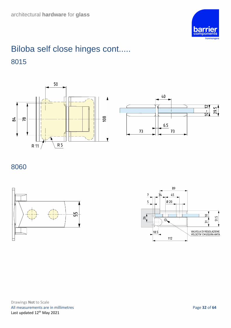
Biloba self close hinges cont.....
8015
8060

architectural hardware for glass
Drawings Not to Scale All measurements are in millimetres Page 33 of 64 Last updated 12th May 2021
HGT100 – Bottom Patch Fitting
Notching detail
There are two different glass cut outs for the HGT-100,
resulting in different bottom clearances.
You can opt for the reduced clearance gap if the floor
condition is good and level.
HGT200 – Top Patch Fitting
Notching detail
GCC would recommend the customer cuts
60mm depth (bottom gap 12mm) to allow for
most floor condition.

architectural hardware for glass
Drawings Not to Scale All measurements are in millimetres Page 34 of 64 Last updated 12th May 2021
Unica Heel Spring – 101E 10
Notching detail
*Distance from floor

architectural hardware for glass
Drawings Not to Scale All measurements are in millimetres Page 35 of 64 Last updated 12th May 2021
G-Tech sliding door system Designed for fixing to 10mm or 12mm toughened glass only Maximum door height 2500mm Maximum Door Width 1360mm Maximum Door Weight 100kg
Note:
10mm Glass 25kg M2
12mm Glass 30kg M2
Tools needed Set of Allen Keys
Glass door to wall installations (Normally Framed Openings).
Track Brackets (5) type GSD153 should be specified. These are supplied without fixings and it is the responsibility of the contractor to supply suitable fixings.
If either end of the track abuts a 90º wall then we recommend the fixing of end bracket GSD440 in lieu of one bracket GSD153.
A = (DP-50) ÷ 2
DP = Door panel width.
Glass door to single glass side panel installations
Track Brackets (6) type GSD151C should be specified.
If either end of the track abuts a 90º wall then we
recommend the fixing of end bracket GSD440 in lieu
of one bracket GSD151C.
A = [OP - (180+180)] ÷ 2
B = [SP - (180+180)] ÷ 2
OP = Over panel width
SP = Side panel width
DP = Door panel width
180
Sliding door
SP
A
180 180
B B
3
W all
40
A
DP
Side Panel
OP
50 A
Sliding door panel W all
DP = daylight opening+50
A

architectural hardware for glass
Drawings Not to Scale All measurements are in millimetres Page 36 of 64 Last updated 12th May 2021
G-Tech sliding door system (continued)
Glass door to glass side panel installation
Track Brackets (7) type GSD151C should be specified. If the end of the track abuts a 90º wall then we recommend the fixing of end
bracket GSD440 in lieu of one bracket GSD151C.
A = [OP - (180+180)] ÷ 2
B = [SP - (180+180)] ÷ 2
OP = Over panel width
SP = Side panel width
DP = Door panel width
Glass calculations To calculate the blank size:
Width: Opening width plus 50mm or 80mm subject to type of installation
Height: Opening height plus 35mm minus 7mm for floor guide.
120
Sliding door panel
SP = Side panel width
AA
180 180
B B
OP = Overpanel width
3
40
180
40
DP = Door width
3
SP = Side panel width

architectural hardware for glass
Drawings Not to Scale All measurements are in millimetres Page 37 of 64 Last updated 12th May 2021
G-Tech sliding door system (continued)
Drilling details
GSD400F (Flat Fixing) GSD400C (Countersunk)
143143

architectural hardware for glass
Drawings Not to Scale All measurements are in millimetres Page 38 of 64 Last updated 12th May 2021
Glass to glass bracket drilling details.
GSD 151F
GSD 151C
G-Tech sliding door system (continued)
Final adjustments
When hanging the door the final height adjustments (to ensure correct position in the floor guide) can be made by the eccentric shaft in the hanger. Simply loosen the fixing bolt and adjust using the ‘tommy bar’ hole. Re-tighten fixing bolt. Track end pieces are fitted by simply pushing them into the tube. The stop fixing bolts must be tightened.

architectural hardware for glass
Drawings Not to Scale All measurements are in millimetres Page 39 of 64 Last updated 12th May 2021
Fixing Bolt
60
35
10/12mm
Fixing Bolt
Tommy Bar Hole
Fixing Bol t

architectural hardware for glass
Drawings Not to Scale All measurements are in millimetres Page 40 of 64 Last updated 12th May 2021
G-Tech pivot - Drilling detail
150
113
65
40
67
50120
50
40
67
50
120
150
113
65
5 5
33
8
Door to f ixed panel
Door to wall
65
19
Ø 32 +0.2
90º
10-12
3 -0.2
Ø 26
65
19

architectural hardware for glass
Drawings Not to Scale All measurements are in millimetres Page 41 of 64 Last updated 12th May 2021
GP10, GP20 Door patch
Notching detail
GP30 Door patch
Notching detail
63
20
73
45
28 ø5 5
45 41
31
ø15 or ø16

architectural hardware for glass
Drawings Not to Scale All measurements are in millimetres Page 42 of 64 Last updated 12th May 2021
GL34S Patch lock
Notching detail
GL34K Patch keep
Notching detail
16
45
65
31
Ø16
ø5 5
65

architectural hardware for glass
Drawings Not to Scale All measurements are in millimetres Page 43 of 64 Last updated 12th May 2021
GX512.1
Glass to wall hinge detail
GX512.2
180° Glass to glass hinge detail
39 30 34
12-14 12-14 20
4 -6
90º open outside only
8
50
20
90º open outside only

architectural hardware for glass
Drawings Not to Scale All measurements are in millimetres Page 44 of 64 Last updated 12th May 2021
GX512.4
90° Glass to glass hinge

architectural hardware for glass
Drawings Not to Scale All measurements are in millimetres Page 45 of 64 Last updated 12th May 2021
558 Latch
Notching details
GX62.1
Connector to fix glass panel to the wall, floor or celling
34
2-3
23
34
12-142-3
wall
f ixed panel
3mm adjustment
architectural hardware for glass
Drawings Not to Scale All measurements are in millimetres Page 46 of 64 Last updated 12th May 2021
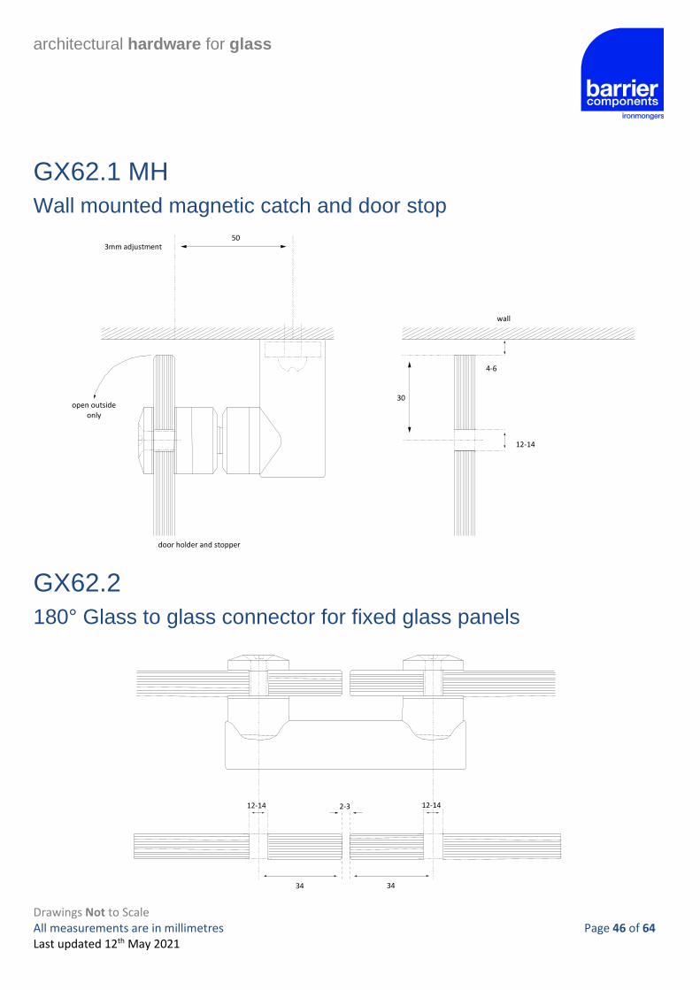
GX62.1 MH
Wall mounted magnetic catch and door stop
GX62.2
180° Glass to glass connector for fixed glass panels
30
12-14
4-6
50 3mm adjustment
door holder and stopper
open outside only
wall
34 34
12-14 12-14 2-3

architectural hardware for glass
Drawings Not to Scale All measurements are in millimetres Page 47 of 64 Last updated 12th May 2021
GX62.2 MH
180° Glass to glass magnetic catch and door stop
GX62.4
90° Glass to glass connector for fixed panels
34
34
2-3
34
34
2-3
12-14
12-14
f ixed panel
f ixed panel
12-14 12-14
34 34 37
12-14
door panel
4-6
90° open outside only
architectural hardware for glass
Drawings Not to Scale All measurements are in millimetres Page 48 of 64 Last updated 12th May 2021
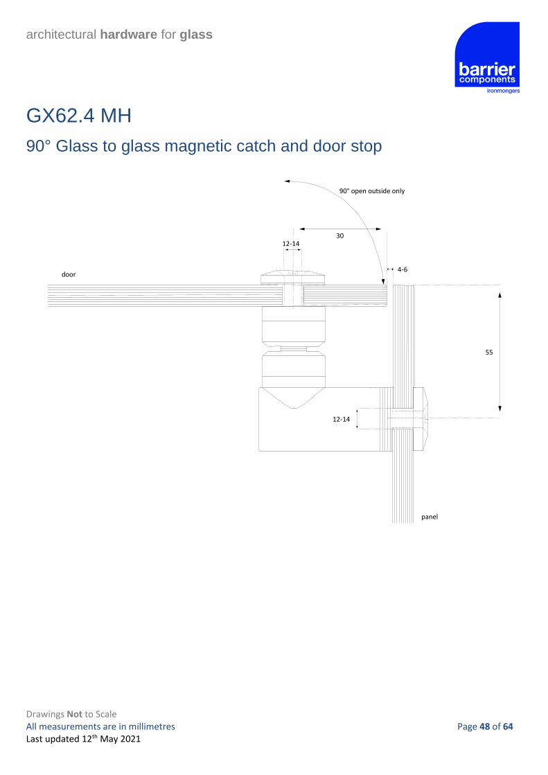
GX62.4 MH
90° Glass to glass magnetic catch and door stop
55
12-14
12-14 30
4-6 door
panel
90° open outside only

architectural hardware for glass
Drawings Not to Scale All measurements are in millimetres Page 49 of 64 Last updated 12th May 2021
Magnetic Seals
Clearances
180°
90°

architectural hardware for glass
Drawings Not to Scale All measurements are in millimetres Page 50 of 64 Last updated 12th May 2021
540004 – 90° Glass to Wall Connector
540006 – 90° Glass to wall hinge
540001 – 180° glass to glass hinge
45
±6
ø32,5
ø44
48
±2mm
76,5
6
To edge of glass
76,5
ø32,5
ø44
±2mm
48
6
To edge of glass

architectural hardware for glass
Drawings Not to Scale All measurements are in millimetres Page 51 of 64 Last updated 12th May 2021
SDT 120 Sliding door system
RH65 Roller hanger
10mm Glass Only
RH68 Roller hanger
10–12mm Glass
Ø 20
38
140
38
50
RH73W Roller hanger
10-12mm Glass
30
36
ø14
42
140

architectural hardware for glass
Drawings Not to Scale All measurements are in millimetres Page 52 of 64 Last updated 12th May 2021
1260 Balustrade clamp with security pin
Drilling detail
28
Hole for fixing pin:
8mm dia. min. for 8mm glass
10mm dia. min. for 10mm glass12mm dia. min. for 12mm glass
Glass Edge
G102C
Drilling detail 90
32m m
+0.2mm
26m m
3 m m + 0.2mm
10-12 mm Glass

architectural hardware for glass
Drawings Not to Scale All measurements are in millimetres Page 53 of 64 Last updated 12th May 2021
F24
Drilling detail
C24
Drilling detail
18mm
10-12 mm Glass
90
32mm
+0.2m m
26mm
3 mm + 0.2mm
10-12 mm Glass
G245F
Cubical drilling option Standard fix option
EDGE OF GLASS
F.F.L.
Ø 2030
45
F.F.L.
Ø 20
72
Seal
3
Edge of Glass

architectural hardware for glass
Drawings Not to Scale All measurements are in millimetres Page 54 of 64 Last updated 12th May 2021
Vitris Glass Locks Inset Glass Lock Overlap Glass Lock
Security Cylinder

architectural hardware for glass
Drawings Not to Scale All measurements are in millimetres Page 55 of 64 Last updated 12th May 2021
XL-GC Series Cabinet Fittings
XL-GC02
XL-GC07
XL-GC04

architectural hardware for glass
Drawings Not to Scale All measurements are in millimetres Page 56 of 64 Last updated 12th May 2021
Adjustable Glass Stand Off
Detail
Sadev Slab Nose
Glass Drilling Detail

architectural hardware for glass
Drawings Not to Scale All measurements are in millimetres Page 57 of 64 Last updated 12th May 2021
Glass Stiffeners
Detail

architectural hardware for glass
Drawings Not to Scale All measurements are in millimetres Page 58 of 64 Last updated 12th May 2021
Pre-assembled Posts
Glass Detail

architectural hardware for glass
Drawings Not to Scale All measurements are in millimetres Page 59 of 64 Last updated 12th May 2021
Barrierslide Crystal
Glass Drilling Detail

architectural hardware for glass
Drawings Not to Scale All measurements are in millimetres Page 60 of 64 Last updated 12th May 2021
Glass Canopy Hardware
Glass Drilling Detail

architectural hardware for glass
Drawings Not to Scale All measurements are in millimetres Page 61 of 64 Last updated 12th May 2021
Glass Canopy Hardware cont…

architectural hardware for glass
Drawings Not to Scale All measurements are in millimetres Page 62 of 64 Last updated 12th May 2021
Weldable Glass Clamps
Glass Drilling Detail Short Single
Long Single

architectural hardware for glass
Drawings Not to Scale All measurements are in millimetres Page 63 of 64 Last updated 12th May 2021
Weldable Glass Clamps cont…
Straight Double

architectural hardware for glass
Drawings Not to Scale All measurements are in millimetres Page 64 of 64 Last updated 12th May 2021
Barrierslide Zircon Glass Drilling Detail