
OPTIMIZATION AND AUTOMATION OF WATER COOLING FACILITY USING PLC
127
OPTIMIZATION AND AUTOMATION OF WATER COOLING FACILITY USING PLC FROM: Engr Rana Muhammad Shakeel [email protected] https://www.facebook.com/EngnrShakeel plz like my page: https://www.facebook.com/Electrical4Electronics For MORE PROJECTS: http://electro-technolgy.blogspot.com The project Optimization and automation of operation of cooling Water Facility in FACT Udyogamandal aims at three objectives. Energy conservation measures by selective switching & speed control, automation of the Plant and energy saving by way of PF improvement. The Cooling water facility in a Process industry offers great scope for energy efficient operation by way of selective switching and speed control of various equipments. As the power consumption of pumps and fans is directly proportional to cube of speed, a reduction in speed, based on quality and quantity of cooling water required, results in saving of huge quantum of energy. A Programmable Logic Controller (PLC) is proposed to be incorporated for the automation part of the project. PLCs have, in a short period of
Transcript of OPTIMIZATION AND AUTOMATION OF WATER COOLING FACILITY USING PLC

OPTIMIZATION AND AUTOMATION OF WATER COOLING FACILITY
USING PLC
FROM:
Engr Rana Muhammad [email protected]://www.facebook.com/EngnrShakeelplz like my page:https://www.facebook.com/Electrical4Electronics
For MORE PROJECTS:http://electro-technolgy.blogspot.com
The project Optimization and automation of operation of
cooling Water Facility in FACT Udyogamandal aims at three
objectives. Energy conservation measures by selective switching
& speed control, automation of the Plant and energy saving by
way of PF improvement. The Cooling water facility in a Process
industry offers great scope for energy efficient operation by
way of selective switching and speed control of various
equipments. As the power consumption of pumps and fans is
directly proportional to cube of speed, a reduction in speed,
based on quality and quantity of cooling water required, results
in saving of huge quantum of energy. A Programmable Logic
Controller (PLC) is proposed to be incorporated for the
automation part of the project. PLCs have, in a short period of

time, played a major role in the evolution of automation, both
in discrete and process application in industrial control. PLCs
are being used extensively in Control systems now, where
electromechanical relays were in use formerly. The introduction
of PLC will make the system more flexible, easily up-gradable
and maintenance-friendly. An attempt is also made to explore the
possibility of introducing equipment-connected PF improving
capacitors for energy saving. Group-connected PF improving
capacitors are being used in FACT, but it is intended for a
reduction in maximum demand rather than energy saving. A part of
the project forms a techno-economic feasibility study of
equipment-connected PF improving capacitors for the equipments
in Cooling Tower.CONTENTS
i. Introduction
ii. Objectives of the Project
i. Selective switching and speed control of Cooling Tower
Fans for energy saving
ii. Switching of Cooling Water Pumps
iii. Techno-economic feasibility study of equipment-
connected PF improving
capacitors
iv. Automation of operation of Cooling Water facility
using PLC
iii. Research Methodology
i. The Plant and the operation
ii. Collection of operational data
iii. Analysis and interpretation
iv. Findings and Recommendations

i. Operation of Cooling Water Facility - Findings
ii. Recommendations for improvement
iii. Automation of operation using PLC
v. Limitations and Constraints of the Project
vi. Scope for future improvements
vii. Conclusion
viii. References
ix. Annexure:
i. Programmable Logic Controllers (PLC)
ii. Variable Frequency Drives
1. INTRODUCTION
The Cooling water facility in a Process industry offers greatscope for energy efficient operation by way of selectiveswitching and speed control of various equipments. By thisproject, the operation of a Cooling Water Facility in FACTUdyogamandal is examined from the energy conservation angle. Asthe power consumption of pumps and fans is directly proportionalto cube of speed, a reduction in speed, based on quality andquantity of cooling water required, results in saving of hugequantum of energy. Incorporation of a Programmable LogicController (PLC) for automation of operation of plant is alsoaimed in this project. Switching of Cooling water pumps andfans, based on requirement can also be achieved by incorporationof PLC. An attempt is also made to explore the possibility ofintroducing equipment-connected PF improving capacitors forenergy saving. FACT, the Fertilisers And Chemicals TravancoreLtd. was founded at the banks of river Periyar in 1944 byDr.C.P.Ramaswamy Iyer. It was then the first large scalefertilizer factory in the entire country and the largest publicsector undertaking in Kerala. The setting up of FACT inUdyogamandal with adequate infrastructure facilities built upalong with it, in course of years attracted a number of otherchemical industries to its neighbourhood. FACT has the widestrange of fertilisers like FACTAMFOS, DAP, NPK mixtures andAmmonium Sulphate to suit all crops and all soils.FACT has,since then, diversified its activities into several fields viz.manufacturing of caprolactam, consultancy services, fabricationof pressure vessels, tanks etc. FACT has six divisions now;three production units, one design and consultancy division(FEDO), one fabrication division (FEW) and a Marketing division
11. OBJECTIVES OF THE PROJECT
i. Selective switching and speed control of cooling tower fans for energy saving.ii. Selective Switching of cooling water pumps.iii. Techno-economic feasibility study of equipment-connectedPF improving capacitors

iv. Automation of operation of cooling water facility using PLC.
i. SELECTIVE SWITCHING AND SPEED CONTROL OF COOLING TOWER FANS
FOR ENERGY SAVING
The entire operation of the existing cooling waterfacility in FACT is manual. Most important drawback of thepresent system is that the operation is inefficient from theenergy point of view. The purpose of the cooling tower is tosupply cooling water to various plants for taking away theexcess heat from the plants. While considering this purpose, theexisting facility meets the requirement as it continuouslysupply enough cooling water to various plants. But the drawbackwith the system is that it does not consider the opportunitiesfor saving the rapidly diminishing energy. The system does nottake any advantage from the dropping temperature in night or theusual low temperature in winter season. By running the fans allthe time without monitoring the outlet water temperature, a lotof energy is being wasted. The first objective of this projectis to examine the potential energy saving by way of selectiveswitching of fans; and by way of running the fans at reducedspeed. A change in speed of any fan will predictably change thepressure rise and power necessary to operate it at the newspeed. The power consumption of fans is directly proportional tocube of speed, and this fact makes obvious the reasons why thespeed of the fans need to be controlled. A reduction in speed offans, based on quality and quantity of cooling water required,results in saving of huge quantum of energy.
Various parameters of the cooling water viz. outlettemperature, flow and pressure are measured and monitoredcontinuously so as to run the equipments in an optimum way.Based on these parameters, fans just required for keeping theoutlet temperature within acceptable value, are only switchedon. When a fan at full speed is not required for keeping thetemperature of water within limit, it is run at reduced speed byusing a Variable Frequency Drive (VFD). The cooling waterfacility at the FACT Udyogamandal is designed for an inlet of 42degree celcius and outlet temperature of 30.5 degrees. Selectiveswitching also helps in energy conservation. During nights andwinter seasons, .there is no need to switch on as many fans as

during day time or summer ii. SELECTIVE SWITCHING OF COOLINGWATER PUMPS
There are seven distribution pumps for the cooling system.The designed discharge requirement is 14100 m3 / nr. Thecapacity of each pump is 3000 m3 / hr. At a time , three pump inanone header and two pumps in Hyam header are in operation withtwo stand by units. Presently, Cooling Water Pumps are runwithout monitoring the actual requirement in various plants. Theoperation people at Cooling Tower run all the pumps as per thedesign parameters without monitoring the quantity of waterrequired by other plants. This results in higher operatingpressure for water when some of the plants stop consumption.And, in order to compensate reduction in flow and subsequentrise in pressure, the operators adjust the control valves so asto keep the pressure within limits. This results in wastage ofenergy at the valves. If switching of pumps is done based onrequirement of plants, this energy which is otherwise beingwasted can be saved. A closed loop control system in which pumpsare selectively switched on together with control of pump speedfor optimum pressure and flow of water would eliminate thisenergy wastage completely. However, this would require VFDs forthe existing 585 kW, 3.3 kV motors, which would be difficult inthe present scenario. Hence, selective switching of CoolingWater Pumps alone is considered for energy saving as an initialimprovement.
iii. TECHNO-ECONOMIC FEASIBILITY STUDY OF EQUIPMENT-CONNECTED PFIMPROVING CAPACITORS
The existing system in FACT looks improvement of powerfactor from maximum demand (MD) only. As a two-part tariff isapplicable for the power drawn by FACT -charges for maximumdemand and energy have to be paid to KSEB - the Company takeseffort to keep the MD minimum by improving pf by switching ongroup-connected capacitors. The Company gets incentive forbetter pf too. However, improvement of pf for better energyutilization has not been tried in FACT. A techno-economicfeasibility study of equipment-connected pf improving capacitorforms as the third objective of this project. The feasibilitystudy comprises two parts viz. technical part for finding out

the capacitance required for bringing the pf to unity and theeconomic evaluation part consisting of life cycle cost analysis.If the future value of the initial investment for the capacitorfor better pf of the motor is less than the sum of futurereturns by way of energy saving, the investment is justified.
Here, the value of capacitance required for bringing thepf of CT Fan to unity is found out by measuring the variousparameters like active power, present pf, running current etc.The resultant saving in energy, by running the motor at unity,is computed by measuring the circuit resistances involved viz.cable resistance, winding resistance, switch, fuse and contactorresistances. The life cycle cost is then calculated to find outwhether the investment is worth making.
Power factor is the cosine of angle between voltage andcurrent in an ac circuit. Distribution lines consume reactivepower depending on series reactance and load current. LTcapacitors are installed on the distribution system onindividual lines at distribution transformers or consumer loadpoints such as motors to reduce system losses and improve systemvoltage as well as system capacity. In addition they provideother advantages for consumers such as reduction in KVA demandlosses and give rise to stable voltage. The optimum benefitdesired from capacitors largely depends on correct positioningcapacitors in the system. However the provision of LT capacitorson individual service such as motors is generally preferred dueto following reasons :i.It can be controlled by same controlgear which controls motor and can be connected at outlet sitesof motor starter ie, parallel to motor winding . The rating ofcapacitors is such that its current shall not exceed 90% of no-load or magnetizing current of motors.
ii.If capacitors are connected on LT motor's terminals, loading current flowing through HT and LT lines ie, cables, motors, etc will also be reduced and hence IA2*R losses of cable, secondary and primary windings of transformers etc can be reduced, iii.Capacitors being directly connected to motors come into operation when motors are in service and switched off automatically when motors are not in use.
ECONOMICS OF CAPACITOR INSTALLATION
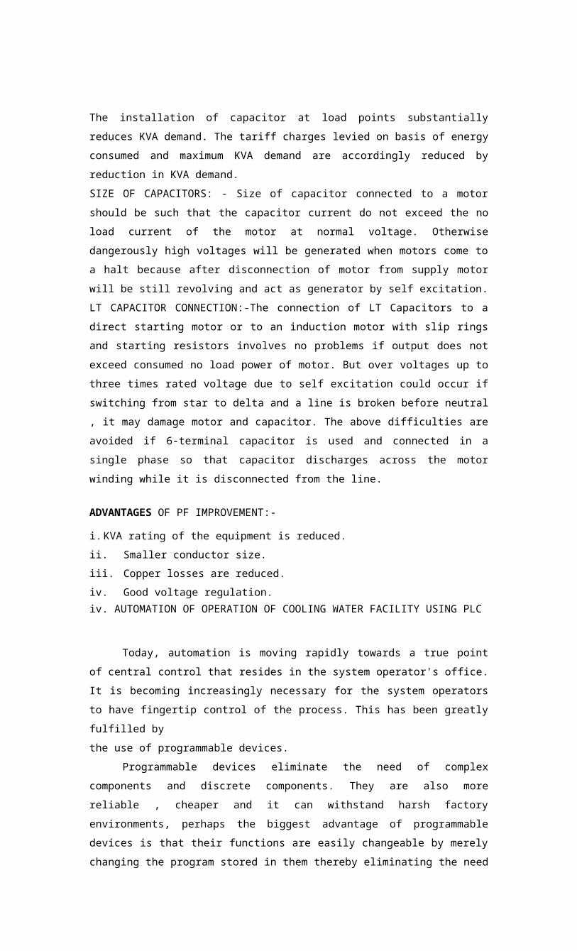
The installation of capacitor at load points substantiallyreduces KVA demand. The tariff charges levied on basis of energyconsumed and maximum KVA demand are accordingly reduced byreduction in KVA demand.SIZE OF CAPACITORS: - Size of capacitor connected to a motorshould be such that the capacitor current do not exceed the noload current of the motor at normal voltage. Otherwisedangerously high voltages will be generated when motors come toa halt because after disconnection of motor from supply motorwill be still revolving and act as generator by self excitation.LT CAPACITOR CONNECTION:-The connection of LT Capacitors to adirect starting motor or to an induction motor with slip ringsand starting resistors involves no problems if output does notexceed consumed no load power of motor. But over voltages up tothree times rated voltage due to self excitation could occur ifswitching from star to delta and a line is broken before neutral, it may damage motor and capacitor. The above difficulties areavoided if 6-terminal capacitor is used and connected in asingle phase so that capacitor discharges across the motorwinding while it is disconnected from the line.
ADVANTAGES OF PF IMPROVEMENT:-
i.KVA rating of the equipment is reduced.ii. Smaller conductor size.iii. Copper losses are reduced.iv. Good voltage regulation.iv. AUTOMATION OF OPERATION OF COOLING WATER FACILITY USING PLC
Today, automation is moving rapidly towards a true pointof central control that resides in the system operator's office.It is becoming increasingly necessary for the system operatorsto have fingertip control of the process. This has been greatlyfulfilled bythe use of programmable devices.
Programmable devices eliminate the need of complexcomponents and discrete components. They are also morereliable , cheaper and it can withstand harsh factoryenvironments, perhaps the biggest advantage of programmabledevices is that their functions are easily changeable by merelychanging the program stored in them thereby eliminating the need

for replacing the whole system . Additional changes can be madeincrementally. They also allow interaction with other systemsand since their outputs are digital, their working can be easilymonitored by computers.In world of automation, the programmable logic controller hasbecome a standard for control. It now not only replaces theearlier relay controls but has taken over many additionalcontrol functions. PLCs are used to synchronize the flow ofinputs from sensors and events with the flow of outputs toactuators and events. This leads to precisely controlled actionsthat permit a tight control of the process or machine .Thisproject is devoted to the principle upon which PLCs operate.
Until the last decade control were realized through thediscrete relays. Relays, though simple, because of theirdiscrete nature and the need for them to be hard-wired for theiroperation become cumbersome and unfit in cases where a lot ofconditions are to be satisfied to achieve automatic control.When the system requirements change, the relay wiring has to bechanged or modified. In an industrial environment, suchmodifications are not only time consuming, but tedious as well.In extreme cases, such as in auto industry, complete panels haveto be replaced as it is not economically feasible to old panelswith each model changeover.
Bigger the process more is the need for a PLC. We cansimply program the PLC to count its inputs and turn thesolenoids on for specified time. Used in industrial and

commercial applications, PLC's act as controllers for machinesand processes . They monitor inputs, make decisions and controloutputs in order to automate machines and processes. Aprogrammable logic controller is a computer designed for use inmachines. Unlike a computer, it has been designed to operate inthe industrial environment and is equipped with special inputsor outputs and a control program language. Initially the PLCwas used to replace relay logic, but its ever-increasing rangeof function means that it is found in many more complexapplications. As the structure of a PLC is same as thoseemployed in computer architecture, it is capable of performingnot only relay switching tasks but also other applications suchas counting, calculating, comparing and the processing ofanalog signals. In this project, automation of water coolingsystem is done using a PLC. The Ladder Diagram technique ofprogramming PLC has been utilized .The implementation of thissystem would replace existing constant speed drive withvariable speed drive and also make the system more reliable andupgradeable in future.

111. RESEARCH METHODOLOGY«
i. THE PLANT AND THE OPERATION
Presently, the cooling water system of FACT petrochemicaldivision is mainly used by 3 plants : Anon, Hyam and Lactum.It's also used in some other sub plant. The cooling water toweris cross flow induced draft splash fill type. It contains 8fans; seven of them are working and one is kept as standby .The hot water inlet of the tower is designed as 42 degrees. Inthis tower the water flows through the two ends of the towerand is situated at the top of the system. In case of singlecell there will be two inlets. The cooling fan is at the topcentre of the cell. As the name specified the air flows crossto the water. The hot water from the hot water inlet is fallingon specially arranged timbers. After falling on timbers itsplashes around. This splashed water drops may be drifted byhigh speed cooling tower fans. This is prevented by placingdrift eliminator. It prevents the water drops through it andmaintained the water inside it. After striking the water dropsin the timbers, they are transformed into tiny drops.Therefore, cross sectional area of water drops increases,therefore the surface contacts with air also increases. Thiswill lead to increase the latent heat of evaporation. Thus thecooling of water is to take place quickly. The whole water isto fall into a common sump. From this cooling water sump thewater is distributed using pumps.
PARTS OF THE COOLING TOWER
FrameCTfan

Hot water inletTimbersDrift eliminator

Air inletPlenumSump
ii. COLLECTION OF OPERATIONAL DATA
GENERAL:

Name ofmanufacturerLocation ofworks
Pahrpur coolingtower Calcutta

DESIGN DATA : Water
flow
Hot water inlet to tower Cold water outlet from tower
14100m3/hr42.630.5

TOWER DATA :

Type of tower No: of fans / cell No: of fans for tower
: Induced draft cross flow : One :Eight

WATER DISTRIBUTION SYSTEM:

No: of headers
FAN DETAILS :
Fan speed Fan motor rating Full load current MountingVoltage ofoperationEnclosureMakeConnection
: Two
1500 rpm 59.7 kw 94 amp foot415 volt ordinaryKirloskarDelta

DISTRIBUTION PUMP:
Pump rating : 585 kwNo: of pumps : 123 ampsFull load current : 7 numbersFrame : KVD 50030Speed of operation : 1000 rpmMounting : flangeEnclosure : ordinaryVoltage of operation : 3.3 kvMake : KirloskarConnection : StarDATA FOR POWER FACTOR CORRECTION:Type of cable : 3 coreArea of crosssection : 3 * 95 sq
mmDC resistance : 0.32AC resistance : 0.385Motor winding resistance
: 0.18 ohm /pha
CABLE LENGTH :400 mDATA FROM ENERGY ANALYZER:Line to line voltage : 425.7 kvFrequency : 49.93 HzCurrent : 90 ampsTrue power in KVA : 50.69 KVAActive power in KVA : 38.47 kwReactive power in KVAR
: 33.08KVAR
Power factor : 0.76

iii. ANALYSIS AND INTERPRETATION
Capacitive kVAR to be added at the motor terminals forimproving the present pf of 0.76 to unity is given by theformula;
kVAR required = kW (tan<D, - tan 02)where O] is the power factor angle before correction and 02 is the power factor angleafter correction. Considering a pf correction to unity,
kVAR required = 38.47 (0.86 - 0)33.08 kVAR
However, the maximum capacitive reactance that can be added to the terminals of amotor should not be more than its no-load reactance. In this case:No-load kVA of the motor = 1.732 * 425.7 *30/1000
= 22.00 kVAR
The various parameters of the fan, after connecting acapacitive reactance of 22.00 kVAR will be:
Active power =38.47 kWReactive power = 40.54 - 22.00 = 18.54kVARApparent power =42.6 kVACurrent drawn by the motor = 55 AReduction in current = 35 APower dissipation in cable for a current of 35 A = 35A2*0.154 * 3
= 565.9 WEnergy consumption considering 330 days of operationfor fan = 565.9 *24 * 330
= 4482.3 kWh

Considering an energy cost of Rs.2.88/ kWh; total amount for one year
= 4482.3 * 2.88 = Rs. 12,909/-
Cost of capacitor (22 kVAR) = Rs.25,000/-
ECONOMIC EVALUATION OF INVESTMENT - RETURN ON INVESTMENT METHOD
By evaluating the net present value of the total cash flows,decision can be made whether the investment is economical ornot. A positive net present value indicates a good investment,and a negative net present value indicates a bad investment.
Net Present Value (NPV) is given by the formula
CFO + CF1/(1+K) + CF2/(1+K)2 + CF3/(1+K)3 + CF4/91+K)4 +CF5/(1+K)5 + CF6/(1+K)6 + CF7/(1+K)7 + CF8/(1+K)8 + CF9/(1+K)9 +CF10/(1+K)10 = 0
Where CFn is the cash flow in each year. Negative sign is givento indicate cash outflow and positive sign is given for cashinflow (saving). K is the discount factor.
ASSUMPTIONS:
• Cost of energy increases by 10% once in every 3 years
• Discount rate k is taken as 12%
Year Energy cost Rs.
Saving Rs. Cash Flow Rs.
1 2.88 12,909 11,5262 2.88 12,909 10,2913 2.88 12,909 9,188

4 3.17 14,200 9,0245 3.17 14,200 8,0576 3.17 14,200 7,1947 3.48 15,620 7,0668 3.48 15,620 6,3099 3.48 15,620 5,63310 3.83 17,182 5,532
Net Saving 79,820
NPV = - 25000 + 79,820 = + 54,820. As NPV is a high positivevalue, this indicates that it will be an economical investment.
IV. FINDINGS AND RECOMMENDATIONS
i. OPERATION OF COOLING WATER FACILITY
OPERATION OF COOLING TOWER PUMP
The distribution pumps are found to work at the full speedat all the time even there occurs a shut down of one or two plants. At present, even a plant takes shut down they are not closing their inlet water valve in order to avoid the chance ofburst in the cooling water pipeline.
So we went for a variable speed drive for the water pumps,there by giving only the required discharge. The control of thevariable speed drive can be given by integrating all the valuepositions at the VFD control input. Thus by varying the speedwe can change the discharge output. But the use of VFD canobtain a power saving taking consideration of continuousworking of the cooling water system.
OPERATION OF COOLING TOWER FANS
The complete operation of all the plants using the coolingwater supply rarely occurs in FACT Udyogamandal. And allcooling water fans are made to work for the whole time. Even ifthe personnel at the control room know about a shut down at theplant the number of fans to be switched off as on is unknown.It requires a periodic or a continuous examination of thetemperature of the sump for the switching purpose. So a personhas to be appointed just for monitoring the temperature and dothe switching operations. This is a cumbersome duty and wastageof labor. These problems can be avoided by an automatedswitching operation of the fans using a PIC. This will accountto saving of annual energy consumption and a reduction inlabor.

ii. RECOMMENDATIONS FOR IMPROVEMENT
Selective switching of Cooling Water Pumps and CoolingTower fans:-Fans will make the system energy efficient. Such asystem takes advantage of the favorable ambient conditions. Bycontinuously monitoring the outlet cooling water temperature,and switching on just enough fans for keeping the temperaturewithin limit, wastage of energy can be minimized. Similarly,monitoring the pressure and flow of cooling water enablesswitching off of Cooling Water Pumps when they are not needed.A closed-loop system incorporating temperature switches for fancontrol, and pressure and flow transducers for pump control isrecommended for the Cooling Water Facility in FACT. And, theoperation of the entire facility is proposed to be controlledusing Programmable Logic Controller (PLC) for making itautomated. The recommended system incorporates a VariableFrequency Drive (VFD) also for speed control of one CoolingTower Fan. The philosophy recommended follows a pattern inwhich each Cooling Tower Fan will be switched on based on thecondition of the temperature switch of the cooling water line.If a fan at normal rated speed is not required for keeping thetemperature, a fan connected to VFD will only be switched on,and it will be allowed to run at a speed sufficient for meetingthe temperature requirement. This ensures that energy is notwasted in fans by way of over cooling the water. A similarlogic, but without a VFD, is recommended for the operation ofCooling Water Pumps. Pumps just required for meeting the demand(required flow at specified pressure) will only be switched on.By adopting such a system, the wastage of energy at controlvalves can be minimized to a certain extent. Though,incorporation of a VFD is essential for complete elimination ofenergy wastage, it is not recommended for the time being. TheCooling Water Pumps are 585 kW, 3.3 kV motors, and since 3.3 kVVFDs are still not very popular in India, that option has notbeen considered in this project. Finally, it is suggested tointroduce equipment-connected pf improving capacitors for thefan motors for energy saving. Introduction of these capacitorswill minimize the energy being dissipated in switchgear, cableand motor winding.

iii. AUTOMATION OF OPERATION USING
PLC INPUTS
0000 Trip switch0001 System in auto0002 Plants in running0003 Power OK0004 Pump A ready0005 Pump A auxiliary
contact0006 Pump B ready0007 Pump B auxiliary
contact0008 Pump C ready0009 Pump C auxiliary
contact0010 Pump D ready0011 Pump D auxiliary
contact0100 Pump E ready0101 Pump E auxiliary
contact0102 Pressure > 2.5
kg/m20103 Flow< 12000 m3/hr0104 Flow < 9000 m3/hr0105 Flow < 6000 m3/hr0106 Flow < 3000 m3/hr0107 Inlet temperature
> 420108 Sump temperature >
31.50109 Outlet
temperature< 30.50110' Fan A ready0111 Fan A auxiliary
contact0200 Fan B ready0201 Fan B auxiliary
contact0202 Fan C ready0203 Fan C auxiliary
contact0204 Fan D ready0205 Fan D auxiliary
contact0206 Fan E ready

0207 Fan E auxiliary contact
0208 Fan F ready0209 Fan F auxiliary
contact0210 Fan G ready0211 Fan G auxiliary
contact0300 Fan H auxiliary
contact0301 Lamp test switchOUTPUTS
1000 System ready indication1001 Command to pump A1002 Pump A ON indication1003 Command to pump B1004 Pump B ON indication1005 Command to pump C1006 Pump C ON indication1007 Command to pump D1010 Pump D ON indication1011 Command to pump E1012 Pump E ON indication1013 Command to switch OFF
pump A1014 Command to switch OFF
pump B1015 Command to switch OFF
pump C1016 Command to switch OFF
pump D1017 Fan A ON1100 Fan A LED ON1101 Fan B ON1102 Fan B LED ON1103 Fan C ON1104 Fan C LED ON1105 Fan D ON1106 Fan D LED ON1107 Fan E ON1110 Fan E LED ON1111 Fan F ON1112 Fan F LED ON1113 Fan G LED ON

1114 Fan G LEDON1115 Fan H LEDON1116 Fan H LEDON

PLC INPUT CONNECTIONS
34V DC + "
Trip Switch —JSystem in Auto —^
Plant Ririning —JPbwnrO.K. —JPuirp A Ready —JRinpA _J
AuxfEaryC ort-act * -----------------Pimp B Ready —| ____________________Pimp B __*
AuxiiaiyCoitact ------------------Riirp C Ready —JPartp C —|
Pjiip D Ready —JPuitpD __JAuxiliiiyCcintact ----------------
PunpE Ready —J ____________RinpE 1Auxiliary Cortact * —
Pressure >2.5Kgn?2 —J _____________Fbw<1200Qrrt%3/h —]
Fbw<9000n^3/li —]
Fbw<6000irf 3fti —^
Fbw<3000ttf-3Th —^
Inlet
terrpeiatLiiB>35 c
—J Surtpternpelainm>35 c—J

l lrjv +Fan DON
(x)Fan D ON Iidication
(X)
Fan EON
(XjFan EON Iidication
(V)
FanF ON Q£FanF ON Iidication
f^jFan G ON (£J
Fan G ON Iidication
fJJFan HON
Q<)F-an H ON Iidication
(Xj

34V DC+
Out]etteir|
teite31c-J
FanA Ready
■
Fan A
AuxiliaryContac t—
J
FanB Ready -J
FanB Auxiliary
Coitact—£
FanC Ready
*
FanC
AuxdiaryCoiiiact —
J
FanD Ready _J
FanD
AuxiliaryContac t
-J
FanE Ready
■
FanE
Auxil
iary
Corif
ect—
J
FanF
Ready
-J
FanF
Auxil
iary
Conta
ct —£
FaziG
Ready
-J
FanG
Auxil
iary
Conta
c t —
^
FaiiH
Auxil
iary
Conta
c t—J
Lamp
Test
Switc
h
_£

1 24 VCOM-"VE
0109
0110
□111
02QD
□201
0202
0BE3
iM
0205
0206
020?
OG08
0209
QG10
0211.
OQ00
0Q01

PLC OUFUTCCONNECTIONS
110 VS ys fern Ready
Indication V-C ommand To Pump A fyQ
Funp A ON IndicationfV}
C ommand To Pump B [%Q
Pump B ON Indcatbn LXl
C ammand To Pump CQ*0_
Pimp C ON Indication
C cmmand To Pump DfjK.}
Pimp D ON IndEation£<}
C ommand lb Pump E LXjFunp E ON Indication(5^)~Coinmand To S with
0FFPuir^AQ<2_
C oinmand To S withOFF Pimp B
1*1C onnnand To S with
OFT Pump CC ommand To S w it: hr<~7Fan A ON
Fan A hdratbn ON
Fan B ON
fxj
Fan B
Indca
tbn
ON
(x)FanC
ON
i/ x )
FanChdkatbnON
1_
a 10 ^ wrenjv/\ OFF FunpD ^-iZ.

110V COM -VE 1000
1001 1002 1013 1004
1005 1006 1007 1010
1011 1012 1013 1014
1015 1016 1017 1020
1021 1022 1023 1024

FLOWCHART
Systemis
ready
Startall thefivepumps
Switchoffpump A
Switchoffpump B


0 ©

Ifflow<=6000mA3/h&
last for 2 min& pressure>2.5kg/ cmA2
No —►

_____i Yes Switchofpump C

Ifflow<=3000mA3/h&
last for 2 min& pressure>2.5kg/cmA2
No

YesT_______
Switch of pumpD
Fan Ais ON
After 2minmeasurethe
sump Temperature
I

Fan Bis ON
After 2minmeasurethe
sump Temperature

After 2minmeasurethe
sump Temperature
After 2minmeasurethe
sump Temperature
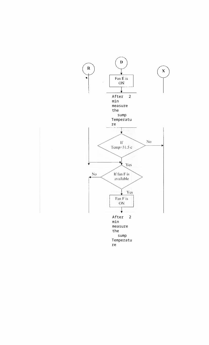
After 2minmeasurethe
sump Temperature
After 2minmeasurethe
sump Temperature


After 2 min measure the
sump Temperature
Fan His ON
SwitchOFF Fan A
X

Reducethe
speedby 20%
After 2 min measure the
sump Temperature

LADDER DIAGRAM
trip

200.00 Oil svstem in auto-M-------I h -------
-0-200.01-o-

ijgplantsrunning
21.02 0.03 powero.k
200.02
200.03
200.01

200Si stem readyindication

200.03 >.04 pump Aread?
O-
10.01
■Ocommand toPa

o.ospg
02 Pa ONindication

298.40

M03 0.06 Pbreadi 10C3
-0command toPb

Pb ON indication

2D0.03
m
Pcready
10.05<h
10.06-O-
Command to
Pc Pc ON
indication

20440

203.03 0.10 cod) 10.07command to
Pel Pd ON
indication

10.
209.

200.03 1 00 Pereadv 10.11
ommandto Pt

101 10.12 Pe ONindication

213.43

1.52pr>2.5kg/eiif2
200

-o00.04 ;1.03 Aow<12000m*3*t

10.02 10.13command toswitch off Pa

200.04 1 g4
HI --------—fifesf-1 1184
fIow<9000mA3/hr
10.14 commandto switchoff Pb

200.04 1.05 Aow<6000«r

iw210.06
command toswitchOff PC

200.04 Ofi

ti»r31-w inlettemp>42deg
sumptemp>31.5deg
11.16
2-DO
05
-o-200.06
command toswitch off Pd
10.06

cutlettemp<30.5deg
.09
200.05
1 1 Fa1fJ,7runiiiQ 2fi s
200.07-o-
209.68-§-
200.0911.00

200*0
11.00

:rwi200.1
200.10-o-

44-

Smsrf200.37
200.11

SwitchONVFD

1.10 11.D1m
0.12

18.1 * 280.08 0.12

2.01if A
-I I---------------
11.02Fb ON
Fbindication

11.1

200.06 200.13

Switch ONVFD

fewrS200.07
200.14-o-

1.10 201M-------W8.12 212 200.08 200.15
200.15
11.03FcON
til 21.32

Feres

11.1 FcindicationON

11.04

fcgf6 200.06 230.16

200.07Fc!readv 0.17 switch
ON VFD

110 2.1M- - -W238.13
2.05
202 .11.05
mis
Ke.32
200.18
11.85
~~O-
11.08
Fd Oh
FdindicationOh
2.04

280.^5
1108

200.19
-o-
200.23

11.07 200.26200.32
200 21

tnr7 200.07 200.032C3.21
209.19 2.06
2.07
233.22
-0-11.07
11.10
switch ON
VFD Fe ON
FeindicationON

20-D.ifJ
11.10

:-r:200.06
2C0 23

2Mb
H4-fel 200.07H I - I I ----------------233.20 11.11 20032 2.06H I - I I ----I I-----H-200.21 2.08 2O0.0E250.25H I --I I ----I I----------kf-
2.09 Fanf ready
203.24
1111-o-
1112
switch ON VFD
FanfON
F anf i n d icati o p n ON
223.^0

11.12

trmsc3 200.06 J.2S

200.07 230.27-§
switch onVFD

293.20 2.06 2.03H I --- -V\------------W
20328 2.10 200.03 M M
----I I ---I I ---M-
200.23-0-11.13
-0-
Fq on
1113

2.11 11.H-o
Fg indicationON

233.40

200.23-o
200.06

rtO2CQ.07
209.1"0"
switch ONVFD

2(58.31

20132

11.15
-0~
FhiVFD)QNtofull speed

tscH290.87
200.33-o
command to reducespeed by
Fh indication11.15
-o-
11.

fef11200.07
ma

■0-
200.33

2M12200.07
as toreduce

0 speed by2:0%

200.34
&t»1321.07 -0

fsertt21.35 - - -0-
3 test switch2i4i
—3commandto reduce speed by 20%

V. LIMITATIONS AND CONSTRAINTS OF THE PROJECT
Data related to design aspects of Cooling Tower wereobtained easily from the operation manuals. However, while goingthrough data collection and analysis, it was observed that manyimportant data related to actual operation were not available.Hot water temperature and cooling water temperature againstnumber of fans running is a data that could be used forestimation of energy saving. This was not available for theseasonal temperature changes of outlet cooling water. Thoughwater requirements of plants under design conditions are given,flow requirements of these plants under varying conditions couldnot be found out. Instrumentation system for the cooling waterfacility, available at present, seems to be inadequate.Similarly, the pressure variation of the cooling water lineowing to reduction in demand by individual plants is being takencare of by the Cooling Tower operators - by throttling ofcontrol valves - but, actual variations have not been recorded.In the absence of the.se data, estimation of number of fans orpumps that would be switched of in a given condition in thepost-implementation scenario becomes difficult. Andsubsequently, that makes the estimation of energy savingresulting from suggested improvements very difficult.
The limitation as stated above is applicable forestimation of energy saving by introducing equipment-connectedpf improving capacitors too. In the absence of relevant data, anassumption was forced to be made regarding average number offans required to be run during a year. The economic evaluationof energy saving due to this change is based on the assumptionthat only four fans would be running throughout the year. A morerealistic estimation could have been made, if sufficient datawere available.
Total power consumption for the Cooling Water Facilitycould not be measured. Without this data, actual benefitsderived - in case of implementation of recommendations - cannotbe verified. The fact that 3.3 kV VFDs are not very popular inIndia was limiting factor in designing an improved systemoperation for Cooling Water Pumps in our project. The

introduction of VFD for Cooling Water Pumps as well would havesaved huge quantum of energy.
For automation purpose, an input indicating that otherplants have started drawing cooling water could not beidentified. If such a device were available, that could be usedfor starting the operation of the Cooling Water Facility in automode. As such, the proposed start-up operation in this projectis initiated by a switch actuated remotely by consuming plants.
VI. SCOPE FOR FUTURE IMPROVEMENT
Since 3.3 kV VFDs are still not very common in India, theoption of using them for Cooling Water Pumps was not recommendedin this project. That alternative can be examined in future, asit seems to be a good proposition once the problems associatedwith HT VFDs are overcome. Total power consumption for theCooling Water Facility could not be measured. Without this data,actual benefits derived - in case of implementation ofrecommendations - cannot be verified. When projects of thisnature are done, preliminary data related to power consumption,annual running hours, temperature variations etc. shall berecorded prior to data analysis and recommendations. An inputcondition indicating starting up and subsequent usage of coolingwater by other plants is required for complete automation of theCooling Water Facility. Process analysis of other plants foridentification of such an input may be incorporated in future.
Vll. CONCLUSION
This project titled 'Optimization and automation ofoperation of cooling tower facility' is a combination ofsoftware programming and hardware interfacing circuit designedfor the automatic control and power saving of the cooling waterin FACT. Our proposed system uses programmable logic controllersand variable frequency drives. Techno economical analysis showsthat there could be a greater improvement in the powerconsumption and also in expenditure.

Vlll. REFERNCES
i.Automating Manufacturing systems with PLCs _ Hugh Jackii. Cooling tower design data sheets,petrochemical division, FACTiii. Omron PLC manualiv. www.industrialtext.comv.www.trilogic_plc.com

IX. ANNEXURE
i. PROGRAMMABLE LOGIC CONTROLLERS
i Brief history
iiDescription
iiiProgramming methods
BRIEF HISTORY
In a PLC system, all control devices are wired to the PLC.In a traditional system, all control devices are wired direotlyto each other. A programmable logic controller, also called aPLC or programmable controller, is a computer-type device usedto control equipment in an industrial facility. The kinds ofequipment that PLCs can control are as varied as industrialfacilities themselves. Conveyor systems, food processingmachinery, auto assembly lines ... you name it and there isprobably a PLC out there controlling it. In a traditionalindustrial control system, all control devices are wireddirectly to each other according to how the system is supposedto operate. In a PLC system, however, the PLC replaces thewiring between the devices. The control program is the computerprogram stored in the PLC's memory that tells the PLC what issupposed to be going on in the system. The use of PLC toprovide wiring connections between system devices is calledsoft wiring.
WHY WE USE PLCs
The soft wiring advantage provided by programmable logiccontrollers is tremendous. In fact, it is one of the mostimportant features of PLCs. Soft wiring makes changes in thecontrol system easy and cheap. If you want a device in a PLC

system to behave differently or to control a different processelement, all you have to do is change

the control program .In a traditional system, making this typeof change would involve physically changing the wiring betweenthe devices, a costly and time consuming endeavor.
In addition to the programming flexibility we just mentioned,PLCs offer other advantages over traditional control systems.These include:-
i High reliabilityiiSmall space requirementsiii Computing capabilitiesivReduced costsv Ability to withstand harsh environmentsviExpandability
Inputs to and outputs from a PLC are necessary to monitor andcontrol a process. Both inputs and outputs can be categorizedinto two basic types: logical or continuous. Consider theexample of a light bulb. If it can be turned on or off, it islogical control. If the light can be dimmed to different levels,it is continuous. Continuous values seem more initiative, butlogical values are preferred because they allow more certainty,and simplified control. As a result most controls applicationsuse logical inputs and outputs for most applications
DESCRIPTION
PLC basically consists of two elements: The Central Processing Unit & input / output system
THE CPU:
The central processing unit is the part of a programmablecontroller that retrieves, decodes, stores, and processesinformation. It also executes the control program stored in thePLC's memory. In essence, the CPU is the brain of a programmablecontroller. It functions much the same way the CPU of a regularcomputer does, except that it uses special instructions andcoding to perform its functions. The CPU has three parts:-Theprocessor The memory system The power supply

The processor is the section of the CPU that codes,decodes, and computes data. The memory system is the section ofthe CPU that stores both the control program and data from theequipment connected to the PLC. The power supply is the sectionthat provides the PLC with the voltage and current it needs tooperate.
THE INPUT / OUTPUT SYSTEM :
The input / output system is the section of a PLC to whichall of the field devices are connected. If the CPU can bethought to be the brain of a PLC, then the I/O system can bethought of as the arms and legs. The I/O system is what actuallyphysically carries out the control commands from the programstored in the PLC's memory. The I/O system consists of two mainparts : The rack and I/O modules. The rack is an enclosure withslots in it that is connected to CPU. I/O modules are deviceswith connection terminals to which the field devices are wired.Together, the rack and the I/O modules form the interfacebetween the field devices and the PLC. When set up properly,each I/O module is both securely wired to its correspondingfield devices and securely installed in a slot in the rack. Thiscreates the physical connection between the field equipment andthe PLC. In some small PLCs the rack and the I/O modules comeprepackaged as one unit.
LADDER LOGIC INPUTS :
PLC inputs are easily represented in ladder logic. In thefigure there are three types of inputs shown. The first two arenormally open and normally closed inputs, discussed previously.The IIT(Immediate input) function allows inputs to be read after

the input scan, while the ladder logic is being scanned. Thisallows ladder logic to examine the input values more often thanonce every cycle. Normally open, an active input x will closethe contact and power to flow. Normally closed, power flowswhen the input x is not open. The immediate inputs will takecurrent values, not those for previous inputscan
LADDER LOGIC OUTPUTS:
In ladder logic there are multiple types of outputs, butthese are not consistently available on all PLCs .Some of theoutputs will be externally connected to devices outside the PLCbut it is also possible to use internal memory locations in thePLC . Different types of outputs are shown The first is anormal output, when energized the output will turn on, andenergize an output. The Circle with a diagonal line through isa normally on output. When energized, the output will turn off.This type of output is not available on all PLC types. Wheninitially energized the OSR ( On Shot Relay ) instruction willturn on for one scan, but then be off for all scans after,until it is turned off. The L(latch) and U(unlatch)instructions can be used to lock outputs on. When an output Lis energized, the output will turn on indefinitely, even whenthe output coil is de energized. The output can only be turnedoff using a U output. The last instruction is the IOT(Immediate Output) that will allow outputs to be updatedwithout having to wait for the ladder logic scan to becompleted. When power is applied the output x is activated forthe left output, but turned off for the output on the right. Aninput transition on will cause the output x to go on forscan( this is also known as a one shot relay).

ii. VARIABLE FREQUENCY DRIVES
An integrated fan speed control solution can lower systemcosts, reduce acoustic noise, power consumption and enhancesystem reliability. Many utilities are now offering rebates forthe installation of VFD's or retro-fitting existing equipmentwith variable frequency drives.
Fan Speed Controlled by
Cooling towers are at the heart of many industrialprocesses. While tower designs vary from manufacturer tomanufacturer, fans are always used to move air through thecooling tower, cooling the process water. Operatingrequirements for a cooling tower may include the ability tostart and stop the fan, change the fan speed (based on the sumpwater temperature).If fan motors are running at constant speed,the problems arising are:-fan speed control not taken intoconsideration at system design stage increased maintenancecosts and process water temperatures are not accuratelycontrolled Applying variable frequency drives or VFD's oncooling towers eliminate many drawbacks associated withstarter-controlled fans. Reduced energy consumption (lower

utility costs), reduced maintenance requirements (personnel &equipment replacement costs) and

process water temperature stabilization are among the benefits.The fan may be spinning when a VFD is commanded to start. A VFDmust correctly identify motor rotation, slow the motor down tozero speed (when opposite rotation is detected), accelerate themotor in the correct direction and not trip on an over-voltageor over-current condition. Mechanical brakes or anti-ratchetingdevices can be used to ensure that a fan doesn't rotate in thewrong direction. A VFD eliminates mechanical and electricalbrakes as well as anti-ratcheting devices, time delay relays,etc. A VFD rectifies ac to dc and then inverts to ac ofrequired frequency. It is possible to achieve speed reductionratio up to 9:1 using VFD.