Programabilni Logički Kontroleri PLC
58
Programabilni Logički Kontroleri PLC 1. PLC hardware 2. PLC programiranje i način funkcionisanja 3. PLC programske funkcije 4. Diskretne I/O funkcije i uređaji
-
Upload
independent -
Category
Documents
-
view
3 -
download
0
Transcript of Programabilni Logički Kontroleri PLC

Programabilni Logički KontroleriPLC
1. PLC hardware
2. PLC programiranje i način funkcionisanja
3. PLC programske funkcije
4. Diskretne I/O funkcije i uređaji

Uvod
• PLC je digitalni elektronski uređaj projektovan da upravlja mašinam i/ili procesima primenjujući sekvencijalno (vremensko ili vođeno događajima) upravljanje.
• PLC je dizajniran za upotrebu u teškim industrijskim uslovima. Može se programirati bez posebnih znanja programiranja i može ga održavati tehničar za održavanje fabrike.
• Neke od prednosti PLC-a su:
1. Fleksibilnost. Jedan PLC može da obradi mnogo različitih operacija. Softverske izmene se lakše implementiraju od hardverskih.
2. Pouzdanost. Solid-state uređaji su pouzdaniji i lakši za održavanje od mehaničkih releja i tajmera.
3. Niža cena. Bazira se na činjenici da poluprovodnička tehnologija (procesori) omogućuje implementaciju složenih funkcija i složenih izračunavanja po veoma niskoj ceni.
4. Dokumentacija. Iz softvera za programiranje je moguće direktno iscrtati šeme regulacionih krugova. Nema potrebe za posebnim crtanjem određenih crteža koji postaju zastareli istog trenutka čim se izvrši neka izmena.

PLC hardware
PS(opcija)Napajanje
CPUProcesor
IM(opcija)Interfejs
SM:DI
SM:DO
SM:AI
SM:AO
FM:- brojanje- pozicija-Zatvorenapovratna petljaFunkcijiskiModuli
CP:- Point-to Point- PROFIBUS- Industrial EthernetSignalni Moduli
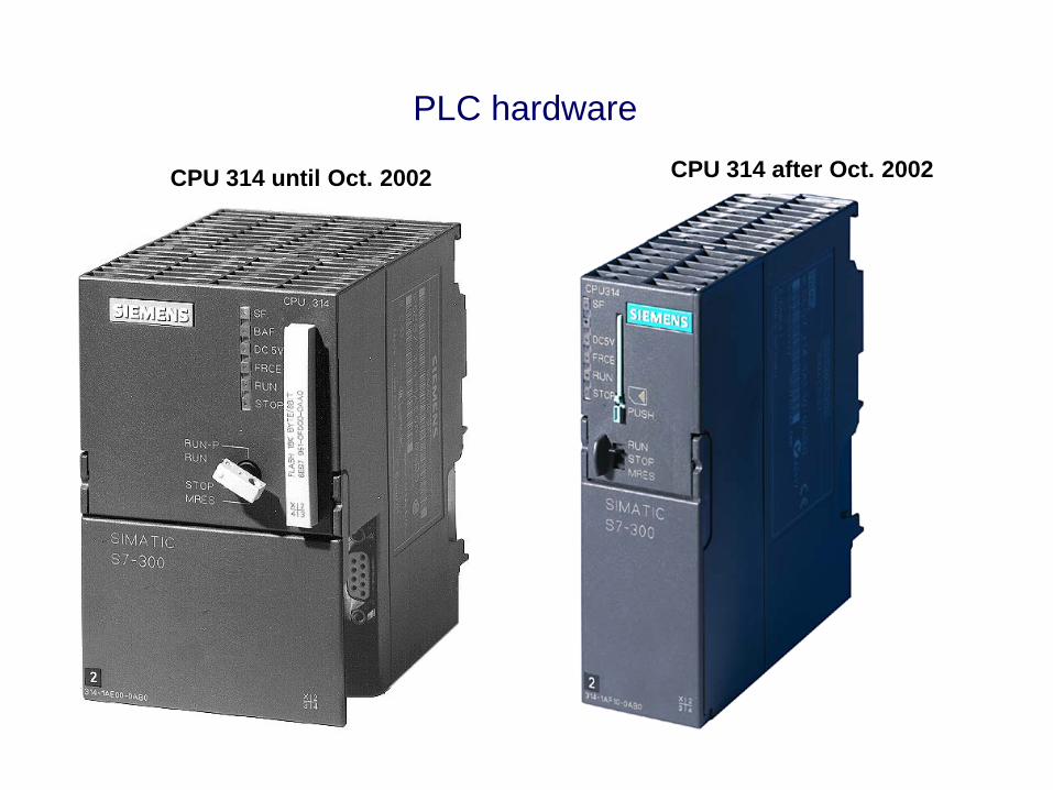
PLC hardware
CPU 314 until Oct. 2002 CPU 314 after Oct. 2002

PLC hardware
S7-400 Automation System

PLC programiranje i funkcionisanje - Ladder Diagram
• LD (Ladder – Lestvičasti Diagram) programski jezik koristi simbole kontakata za formiranje dijagrama koji su veoma slični kontaktorskim šemama.
• Simbol za normalno otvoreni kontakt podseća simbol za električni kondenzator.
• Simbol za normalno zatvoren kontakt je isti kao za otvoreni kontakt sa dijagonalnom linijom preko.
• Simbol za izlaz se sastoji od dve male zagrade.
• Svaki kontakt i izlazni simbol ima broj upisan odmah ispod (ili iznad) njega.Ovaj broj identifikuje lokaciju u procesorskoj memoriji (RAM), gde se čuva vrednost (podatak) sa tog kontakta ili izlaza.
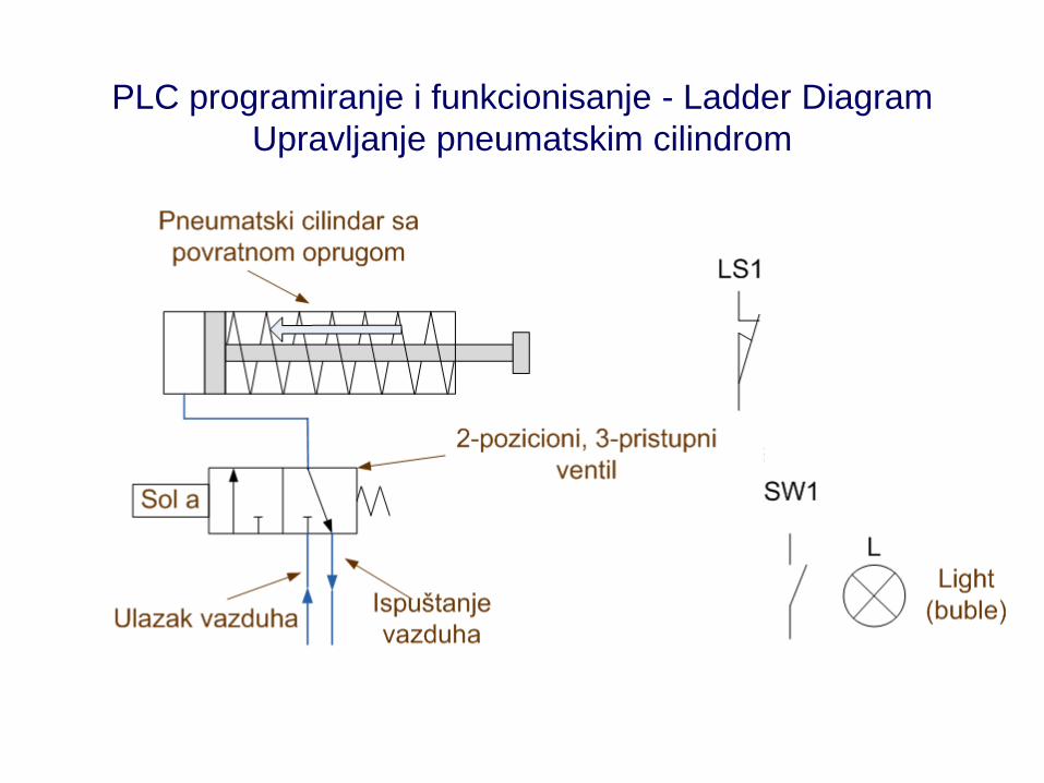
PLC programiranje i funkcionisanje - Ladder DiagramUpravljanje pneumatskim cilindrom


PLC programiranje i funkcionisanje - Ladder DiagramUpravljanje pneumatskim cilindrom

PLC programiranje i funkcionisanje - Ladder DiagramUpravljanje pneumatskim cilindrom

Slika na prethodnom slajdu prikazuje ulazne, procesorsku i izlazne jedinice PLC-a korištene za upravljanje pneumatskim cilindrom.
Kvadrati (1,2, 3 i 4) u ulaznom modulu IM:1 sadrže konvertore koji konvertuju prekidačke ulaze u logičke naponske nivoe.
Četiri linije povezuju ulazne “kvadratiće” sa memorijskim ćelijama (lokacijama) koje čuvaju informacije o statusu odgovoarajućih ulaza.
Gornja desna ćelija ulaznog dela memorije je povezana sa ulazom 1, ulaznog modula IM-1, tak oda nosi oznaku IM: 1-1.
Krećući se nalevo kroz memorijske ćelije njihove oznake su IM:1-2, IM:1-3, IM:1-4. Vrednost 0 u memorijskoj ćeliji IM:1-1 znači da je taster START povezan sa ulazom 1 otvoren, što i jeste.
Jedinica u memorijskim ćelijama IM:1-2 and IM:1-3 označava da su prekidači STOP i LS1zatvoreni, što i jeste.
Nula u ćeliji IM:1-4 pokazuje da je SW1 otvoren.
ZAPAMTITE! Ulazni podaci na lokacijama IM:1-2 i IM:1-3 daju informaciju da su kontakti priključeni na odgovarajuće ulaze zatvoreni. Nemamo informaciju da li su to neaktivirani NC ili aktivirani NO kontakti.
PLC programiranje i funkcionisanje - Ladder DiagramUpravljanje pneumatskim cilindrom

PLC programiranje i funkcionisanje - Ladder DiagramUpravljanje pneumatskim cilindrom
Kvadratići(1, 2, 3 i 4) izlaznog modula OM:1 sadrže prekidačka kola koji koriste logičke naponske nivoe (vrednosti izlaznih memorijskih ćelija) kako bi aktivirali ili deaktivirali izlazne uređaje (stanja ON ili OFF).
Linija povezuje izlazni kvadratić 1 sa gornjom desnom izlaznom memorijskom ćelijom, tako da je njena adresa OM:1-1.
Krećući se nalevo od ćelije OM:1-1 su ćelije OM:1-2, OM:1-3, and OM:1-4.
Nule u memorijskim ćelijama OM:1-1 i OM:1-2 znači da su solneoid i sijalica isključeni (stanje OFF).

PLC programiranje i funkcionisanje - Ladder DiagramUpravljanje pneumatskim cilindrom
Ladder diagram PLC program - Ladder diagram language
Upoređujući PLC program sa lestvičastim dijagramom (kontaktorskom šemom KŠ) mogu se uočiti sličnosti, ali i neke razlike.
KŠ ima tri linije (prečage, lestvice) a program samo dve. Druga linija se izgubila pošto je Sol a, izlazni uređaj povezan na izlazni terminal OM:1-1. Iz tog razloga se on ne pojavljuje u programu. Izlaz OM:1-1 na prvoj liniji programa kontroliše relej CR1, koji aktivira Sol a. Prva linija programa sadrži prve dve linije kontaktorske šeme.

PLC programiranje i principi funkcionisanja - Ladder Diagram
LD programski jezik postavlja određena ograničenja po pitanju pisanja programa, i ta
ograničenja variraju od proizvođača do proizvođača uređaja. Tipična ograničenja su:
1. Izlaz mora biti na desnom kraju grane.
2. Tok energije mora biti s leva na desno, nagore ili nadole.
3. Energija NE SME da teče s desna na levo.
4. Broj kontakata povezanih na red je maksimalno 11 (ili neki drugi broj postavljen od
strane proizvođača).
5. Broj paralelnih kontakata je maksimalno 7 (ili neki drugi broj postavljen od strane
proizvođača).
6. Grana može da ima samo jedan izlaz.
7. Izlaz mora da bude postavljen u najgronjoj liniji grane.

PLC programming and operation - Ladder Diagram Programming
• U relejnoj logici, tok energije s desna na levo se naziva “puzajući put”. Puzajući putevi nisu dozvoljeni u PLC programiranju, što pojednostavljuje samo progrmiranje ali i zahteva prilagođenje relejne logike (dijagrama). Puzajući putevi se moraju konvertovati u odgovarajuće ladder dijagrame (kontaktorske šeme) koji ih ne sadrže.
• U LD programskom jeziku otvoreni i zatvoreni kontakti su u stvari programske instrukcije, a ne preslikani kontakti kontaktorskih šema. Oni govore PLCu kako da interpretira 1 i 0 koji se nalaze na ulaznim memorijskim lokacijama (za svaki pojedinačni kontakt). Simbol normalno otvorenog kontakta (┤├) daje PlCu instrukciju da interpretira 1 kao TAČNO (TRUE) a 0 kao NETAČNO (FALSE). Ako PLC uspe da pronađe TAČAN put od ulaza do izlaza, tada je izlaz ON, u odgovarajuću izlaznu memorijsku ćeliju se upisuje 1 i aktivira se odgovarajući izlazni uređaj. Ako nije pronađen tačan put, tada je izlaz OFF, i upisuje se 0 u odgovarajuću izlaznu memorijsku lokaciju.
• Simbol NO kontakta se može koristiti i za NO i za NC fizičke kontakte. Naravno, mi kreiramo rezultate u skladu sa potrebama.

PLC programming and operation - Ladder Diagram Programming

PLC programming and operation - Ladder Diagram Programming

PLC programming and operation - Ladder Diagram Programming
When a PLC is in the RUN mode, the processor repeats the following four-step cycle:
1. Input scan. Store a new image of input conditions.
2. Program scan. Derive the new image of output conditions.
3. Output scan. Transfer the new image of output conditions to output devices.
4. Housekeeping tasks. Communication and other tasks.

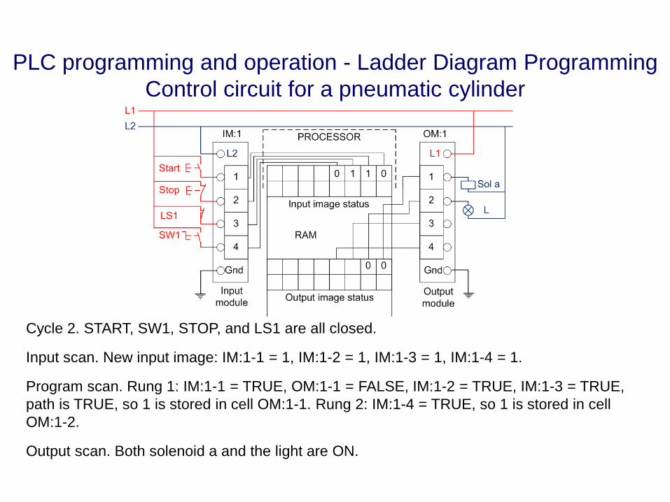
PLC programming and operation - Ladder Diagram ProgrammingControl circuit for a pneumatic cylinder
Cycle 1. start and SW1 are open, stop and LS1 are closed.
Input scan. New input image is IM:1-1 = 0, IM:1-2 = 1, IM:1-3 = 1, IM:1-4 = 0.
Program scan. Rung 1: IM:1-1 = FALSE, OM:1-1 = FALSE, IM:1-2 = TRUE, IM:1-3 = TRUE, path is FALSE, so 0 is stored in cell OM:1-1. Rung 2: IM:1-4 = FALSE so 0 is stored in cell OM:1-2.
Output scan. Both solenoid a and the light are off.
PLC programming and operation - Ladder Diagram ProgrammingControl circuit for a pneumatic cylinder
Cycle 2. START, SW1, STOP, and LS1 are all closed.
Input scan. New input image: IM:1-1 = 1, IM:1-2 = 1, IM:1-3 = 1, IM:1-4 = 1.
Program scan. Rung 1: IM:1-1 = TRUE, OM:1-1 = FALSE, IM:1-2 = TRUE, IM:1-3 = TRUE, path is TRUE, so 1 is stored in cell OM:1-1. Rung 2: IM:1-4 = TRUE, so 1 is stored in cell OM:1-2.
Output scan. Both solenoid a and the light are ON.
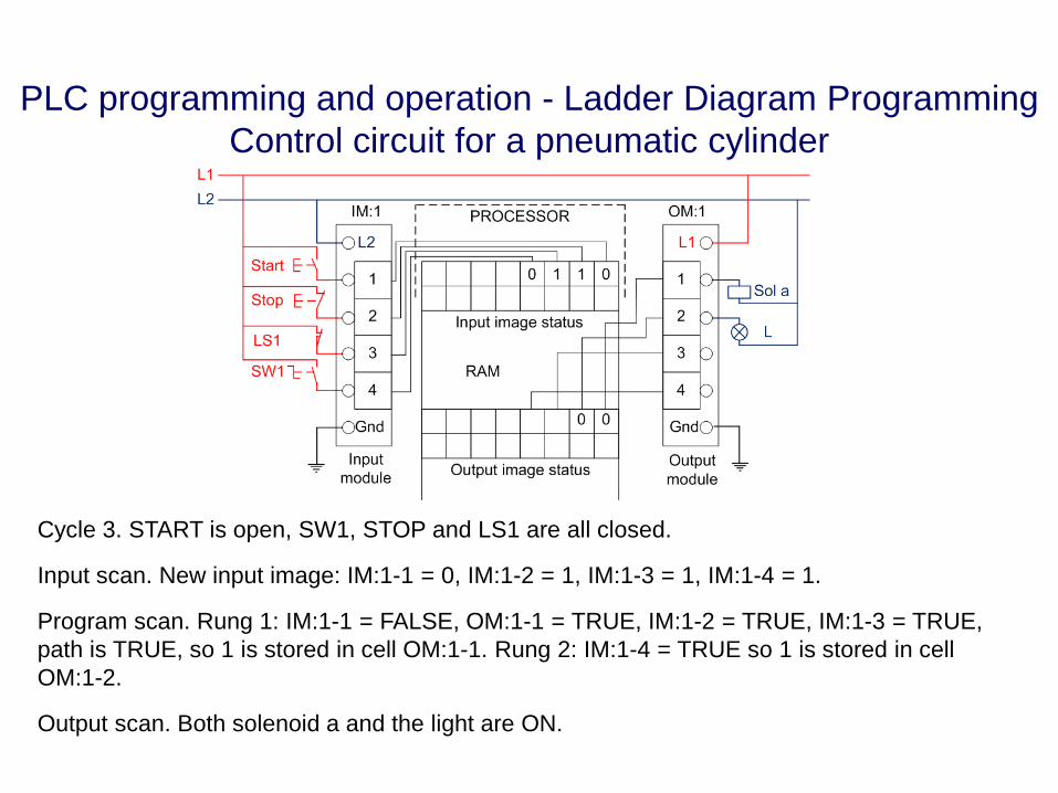
PLC programming and operation - Ladder Diagram ProgrammingControl circuit for a pneumatic cylinder
Cycle 3. START is open, SW1, STOP and LS1 are all closed.
Input scan. New input image: IM:1-1 = 0, IM:1-2 = 1, IM:1-3 = 1, IM:1-4 = 1.
Program scan. Rung 1: IM:1-1 = FALSE, OM:1-1 = TRUE, IM:1-2 = TRUE, IM:1-3 = TRUE, path is TRUE, so 1 is stored in cell OM:1-1. Rung 2: IM:1-4 = TRUE so 1 is stored in cell OM:1-2.
Output scan. Both solenoid a and the light are ON.

PLC programming and operation - Ladder Diagram ProgrammingControl circuit for a pneumatic cylinder
Cycle 4. START and LSI are open, STOP and SW1 are closed.
Input scan. New input image: IM:1-1 = 0, IM:1-2 = 1, IM:1-3 = 0, IM:1-4 = 1.
Program scan. Rung 1: IM:1-1 = FALSE, OM:1-1 = TRUE, IM:1-2 = TRUE, IM:1-3= FALSE, path is FALSE, so 0 is stored in cell OM:1-1. Rung 2: IM:1-4 = TRUE so 1 is stored in cell OM:1-2.
Output scan. Solenoid a is OFF, the light is ON.

PLC programming functions – Timer function
• The Timer is the most frequently used PLC function, and Time Delay On is the most
common timing function.
• Both Time Delay On and Time Delay Off are used in PLCs.
• Two types of timers are used in programmable logic controllers:
1. one-input nonretentive timer
2. two-input retentive timer.
• The nonretentive timer has one input, one output, and a preset delay time.
• The retentive timer has two inputs, one output, and two status bits that can be used as
internal outputs. The inputs are the Enable/Reset line and the Run line. The output is the
Done.

PLC programming functions – Timer function
A generic, two-input, retentive timer and a typical timing diagram. The timer is shown with the output address T:12. In the timing diagram, Enable/Reset, and Run are inputs, T:12, T:12-E, and T:12-R are outputs. Observe that the timing diagrams of T:12-E and Enable/Reset match exactly, but the diagrams of T:12-R and Run do not. Output T:12-R is ON only when Enable/Reset is ON, Run input is ON, and Done is OFF. Output T:12 (Done) is ON only after the preset time delay has been reached, and it goes OFF when Enable/Reset goes OFF.

Traditional Timer Functions
S5T#35s
S_PEXT
TV
Q
BI
R
I 0.7
I 0.5
MW0
QW12
T44
BCD
=M8.5
S
T44S_OFFDT
TV
Q
BI
R
I 0.7
I 0.5
S5T#35s
MW0
QW12BCD
=M8.5
S
T44S_ODTS
TV
Q
BI
R
I 0.7
I 0.5
S5T#35s
MW0
QW12BCD
=M8.5
S
T44S_PULSE
TV
Q
BI
R
I 0.7
I 0.5
S5T#35s
MW0
QW12BCD
=M8.5
S
Pulse Timer (SP) Extended Pulse (SE)
Stored ON Delay (SS)
T44S_ODT
TV
Q
BI
R
I 0.7
I 0.5
S5T#35s
MW0
QW12BCD
=M8.5
S
ON Delay (SD)
OFF Delay (SF)

Example
A I 0.7L S5T#35sSD T4A I 0.5R T4L T4T MW0LC T4T QW12A T4= Q8.5
STL
Example of Timer Function: ON Delay (SD)LAD
T4S_ODT
TV
S Q
BCD
BI
R
I 0.7
I 0.5S5T#35s
Q8.5
MW0
QW12
FBD
S_EVERZ
TV
Q
BI
R
I 0.7
I 0.5
S5T#35s
MW0
QW12
T4
BCD
=Q8.5
S
RLO at S
RLO at R
Time operation
Q
Units of time: 0 to 999 (BCD-coded)
0.01s <--0.1s <--
1s <--10s <--
0 00 11 01 1
Data type “S5TIME”
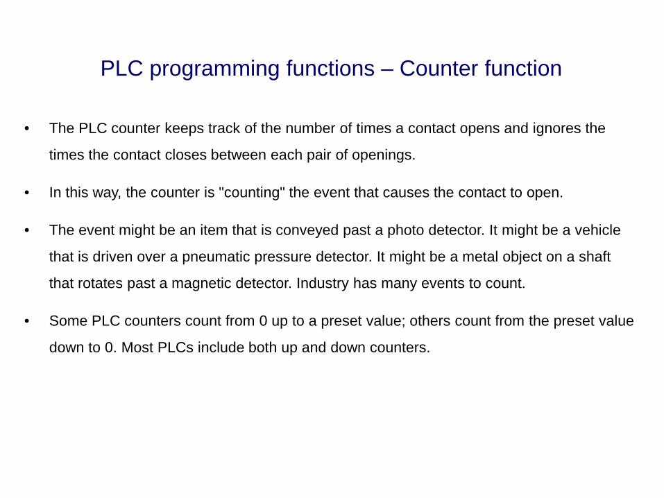
PLC programming functions – Counter function
• The PLC counter keeps track of the number of times a contact opens and ignores the
times the contact closes between each pair of openings.
• In this way, the counter is "counting" the event that causes the contact to open.
• The event might be an item that is conveyed past a photo detector. It might be a vehicle
that is driven over a pneumatic pressure detector. It might be a metal object on a shaft
that rotates past a magnetic detector. Industry has many events to count.
• Some PLC counters count from 0 up to a preset value; others count from the preset value
down to 0. Most PLCs include both up and down counters.

PLC programming functions – Counter functionA generic, two-input counter. The counter is shown with the output address C:7, the preset value 120, and the counter register address RA:0027. When the Enable/Reset line is OFF, the counter ignores changes on the count input line, output (C:7) is OFF, and the count register (RA:0027) is reset to 0. When the Enable/Reset line is ON, the counter increments the count by 1 each time the count input line goes from OFF to ON. The counter output (C:7) is OFF until the count in RA:0027 reaches the preset value (120). At that time, C:7 is turned ON and remains ON until Enable/Reset is turned OFF. The counter continues to increment the count register beyond the preset value, even though the output is ON, indicating it is done.

Traditional Counter FunctionsSTL
A I 0.4CU C5A I 0.5CD C5A I 0.3L C#5S C5A I 0.7R C5L C5T MW4LC C5T QW12A C5= Q8.3
LAD
QI 0.4
I 0.5
CU
I 0.7
C#5
S_CUD
CD
SI 0.3
PV
R
Q 8.3
CV
CV_BCD
MW 4
QW 12
C5
Q
FBD
I 0.4
I 0.5
I 0.7
C#5
I 0.3
Q
CU
S_CUD
CD
S
PV
R
Q 8.3
CV
CV_BCD
MW 4
QW 12
C5
=Q
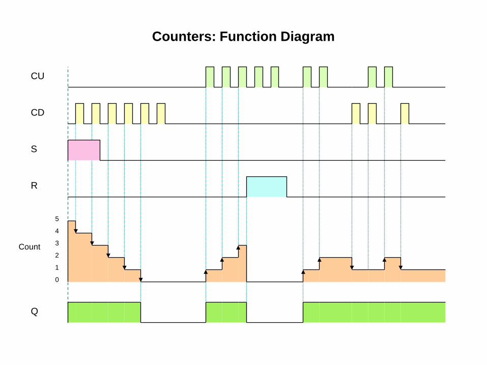
Counters: Function Diagram
CU
CD
S
R
Q
Count
5
4
3
2
1
0

PLC programming functions – Counter function
Exercise: explain the LD for atwo-counter PLC program maintains a count of the number of customers in a store.

PLC programming functions – Sequencer Function• The sequencer function goes through a sequence of steps, producing specified conditions
in a number of ON/OFF outputs at each step.
• The specified output pattern for each step is stored in one word of memory, and patterns
for successive steps are stored in successive memory cells.
• Each bit in the word is matched with one output (bit 0 is matched with output No.1, bit 1 is
matched with output No.2, . . . , bit 7 is matched with output No.8).
• If a bit holds a logical 1, the sequencer turns the matching output ON (or leaves it ON).
• If a bit holds a logical 0, the sequencer turns the matching output OFF (or leaves it OFF).
• The number of outputs that a sequencer can control depends on the word size of the
PLC. An 8-bit PLC can control up to 8 outputs, and a 16-bit PLC can control up to 16
outputs.
• Additional sequencer functions can be used to control additional outputs. For example,
two 16-bit sequencers can control up to 32 outputs.

PLC programming functions – Sequencer Function• A generic sequencer with timed
steps.
• The timer is enabled by it’s own
output, causing it to reset
immediately after it has finished
a 30-s delay.
• After it has reset, the timer
immediately begins another 30-
s delay (assuming OM:1-1 is
ON).
• The timing diagram illustrates
the sequence of pulses
produced by the timer in this
circuit.

PLC programming functions – PID Control Function
In some PLCs, the PID control function is built into an I/O module.
In other PLCs, the PID function is programmed as a rung in the ladder diagram program.
Enable: Enables the function when ONManual/Auto: OFF for manual, ON for automatic controlSetpoint: Register that holds the process variableError: Register that holds the errorOutput: Register that holds the outputP: Register that holds the proportional gain settingI: Register that holds the integral action time constantD: Register that holds the derivative time setting
A generic PID controller function

DISCRETE I/O FUNCTIONS AND DEVICES - BINARY OPERATIONS
I 0.0 I 0.1 Q 8.0
Q 8.1 I 1.0
I 1.1 P =
& M1.0 M8.0
T4
S_ODT
TV
S Q
BCD
BI
R
I 0.7
I 0.5S5T#35s
Q8.5
MW0
QW12
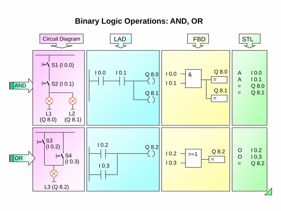
Binary Logic Operations: AND, OR
I 0.2
I 0.3>=1
=Q 8.2 O I 0.2
O I 0.3= Q 8.2
I 0.0 I 0.1 Q 8.0
Q 8.1
LAD
=Q 8.0&I 0.0
I 0.1
=Q 8.1
FBD
A I 0.0A I 0.1= Q 8.0= Q 8.1
STL
I 0.2
I 0.3
Q 8.2
L3 (Q 8.2)
S3(I 0.2)
S4(I 0.3)OR
AND
L1(Q 8.0)
S1 (I 0.0)
S2 (I 0.1)
L2 (Q 8.1)
Circuit Diagram

Binary Logic Operations: Exclusive OR (XOR)
I 0.4
I 0.5XOR
=Q 8.0
I 0.4 I 0.5
I 0.4 I 0.5
Q 8.0
LAD
>=1=
Q 8.0&I 0.4
I 0.5
&I 0.4
I 0.5
FBD
A I 0.4AN I 0.5OAN I 0.4A I 0.5= Q8.0
STL
X I 0.4X I 0.5= Q8.0

Assignment, Setting, Resetting
(S)Q 8.1I 1.2 I 1.3
I 1.2 &
SQ 8.1
I 1.3
I 1.4 >=1
RQ 8.1
I 1.5
A I 1.2A I 1.3S Q 8.1
O I 1.4O I 1.5R Q 8.1
I 1.0 &
=Q 8.0
I 1.1
A I 1.0A I 1.1= Q 8.0Assignment
Set
Reset(R)
Q 8.1I 1.4
I 1.5
( )Q 8.0I 1.0 I 1.1
LAD FBD STL

RLO – Edge Detection
A I 1.0A I 1.1FP M1.0= M8.0
A I 1.0A I 1.1FN M1.1= M8.1
PI 1.0 I 1.1 M1.0 M8.0
NI 1.0 I 1.1 M1.1 M8.1
I 1.0
I 1.1 P =
& M1.0 M8.0
I 1.0
I 1.1 N =
& M1.1 M8.1
I 1.0
I 1.1
RLO
M1.0
M8.0M8.1
M1.1
LAD FBD STL
OB1 Cycle
Example

Digital Operations
I 0.0 I 0.1 Q 8.0
Q 8.1 I 1.0
I 1.1 P =
& M1.0 M8.0
T4
S_ODT
TV
S Q
BCD
BI
R
I 0.7
I 0.5S5T#35s
Q8.5
MW0
QW12

DEC: + 662 BIN.: 2# 0 0 0 0 1 0 1 0 0 1 0 1 1 0000123456789101112131415
DEC: - 662
Integer (INT, 16-Bit Integer) Data Type
Value range -32768 to +32767(without sign: 0 to 65535)
Display Formats:
+21+22
+24 6 x 160 = 69 x 161 = 144
2 x 162 = 512662
+27+29
+25+26+28
Arithmeticoperations: such as + I, * I, <I, ==I
+210+211
+212+213
+214-215
- 662
Signpositivenumbers
Signnegativenumbers
Representation as Twos complement
+23 +21
+ 662
10 x 160 =166 x 161 = 96
13 x 162 = 3328
6487415 x 163 = 61440
BIN.: 2# 1 1 1 1 0 1 0 1 1 0 1 0 1 0110123456789101112131415
HEX: W#16 9 62#0
HEX: W#16# 6 ADFwithoutsign
withoutsign

DEC: L# +540809
Double Integer (DINT, 32-Bit Integer) Data Type
Value range L# -2147483648 to L#+2147483647(without sign: 0 to 4294967295)
Display Formats:
Operations: such as + D, * D, <D, ==D
(without sign)
0 0 0 8 4 0 8 9HEX: DW#16#
0 0 0 0 0 0 1 0 0 0 1 0 0 1100001000000000000BIN.: 2#012345678910111213141516171819202122232425262728293031
Representation as Twos complement
(without sign)
F F F 7 B F 7 7HEX: DW#16#
1 1 1 1 1 1 0 1 1 1 0 1 1 1011110111111111111BIN.: 2#012345678910111213141516171819202122232425262728293031
DEC: L# -540809
Signnegativenumbers
Signpositivenumbers

REAL (Floating-point Number, 32 Bit) Data Type
General format of a Real number = (Sign) • (1.f) • (2e-127)
Real no. = +1.5 * 2 126-127 = 0.75
0 0 0 0 0 0 0 0 0 0 0 0 0 0 0 0 00 0 1 1 1 1 1 1 0 1 0 0 0 0 0
Sign ofReal no.
15 14 13 12 11 10 9 8 7 6 5 4 3 2 1 031 30 29 28 27 26 25 24 23 22 21 20 19 18 17 16
e = Exponent (8 Bit) f = Mantissa (23 Bit)
2021222324252627 2-232-1 2-2 2-4 .....2-3
Operations: such as + R, * R, <R, ==Rsin, acos, ln, exp, SQR
Example: 0.75
Value range -3.402823•10+38 to -1.175495•10-38 , 0.0, +1.175495•10-38 to +3.402823•10+38

The BCD Code for Inputting and Outputting Integers
6920
Value range 16 Bit: - 999 to + 99932 Bit: -9999999 to + 9999999
Conversionoperations: BTI, BTD, ITB, DTB
(no arithmetic!)
0 0 0 0 1 0 1 0 0 1 0 1 1 000000000000000xxx0BIN.: 2#
BIN.: 2# 0 0 0 0 1 0 1 0 0 1 0 1 1 000
Sign (+) 92
16 Bit:
32 Bit:
Sign (+)
6
6920000
DEC: + 662HEX: W#16# 2 9 60
DEC: + 662HEX: DW#16# 0 0 0 0 2 9 6

Conversion Operations BCD <-> Integer
0 8 1 5NumberEntered in BCD
Number displayedin BCD
ConversionBCD->Integer
IN
BCD_IEN
ENO
OUT
INIW4
MW20
IN
I_BCDEN
ENO
OUT
INMW10
QW12
FBD
L IW4BTIT MW20
L MW10ITBT QW12
STL
Task
ConversionBCD<-Integer
User program with Integermath operations
0 2 4 8
IN
BCD_IEN ENO
OUTINIW4 MW20
I_BCD
IN
EN ENO
OUTMW10 QW12
LAD
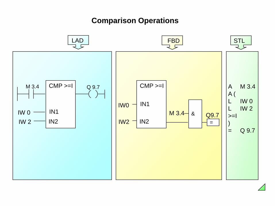
Comparison Operations
STL
A M 3.4A (L IW 0L IW 2>=I)= Q 9.7
FBD
M 3.4IW0
IW2 =Q9.7&
CMP >=I
IN1
IN2
LAD
IW 0IW 2
M 3.4 Q 9.7CMP >=I
IN1IN2

LAD FBD STL
Basic Mathematical Functions
AdditionL MW4L MW10+ IT MW6MW10
ADD_I
IN2
EN
ENO
OUTIN1MW4
MW6
MW10
ADD_I
IN2
EN ENO
OUTIN1MW4
MW6
Subtrac-tion
MW12
SUB_I
IN2
EN
ENO
OUTIN1MW8
MW6L MW8L MW12- IT MW6
SUB_I
IN2
EN ENOIN1MW8
MW12 MW6OUT
Multipli-cation
MD12
MUL_DI
IN2
EN
ENO
OUTIN1MD6
MD66L MD6L MD12* DT MD66
MD6MD12
MUL_DIEN ENOIN1
MD66IN2
Division
MD4
DIV_R
IN2
EN
ENO
OUTIN1MD40
MD32 L MD40L MD4/ RT MD32
MD40
MD4
EN ENOIN1IN2 MD32OUT
DIV_R

Storing Process Data in Data Blocks
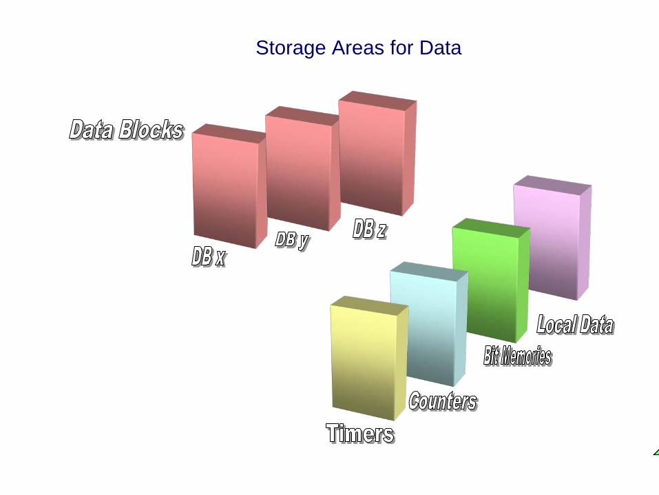
Storage Areas for Data

Data Blocks (DBs)
FunctionFC10
FunctionFC20
FunctionBlockFB1
OB1Global (shared)
data
DB20
Accessible to all blocks
Instance Data
DB5
Instance DB for FB1

Overview of Data Types in STEP 7
Elementarydata types(up to 32 bits)
Complexdata types(longer than 32 bits)
User-defined data types(longer than 32 bits)
• Bit data types (BOOL, BYTE, WORD, DWORD, CHAR)
• Mathematical data types (INT, DINT, REAL)
• Time types (S5TIME, TIME, DATE, TIME_OF_DAY)
• Time type (DATE_AND_TIME)
• Array (ARRAY)
• Structure (STRUCT)
• Character chain (STRING)
Data type UDT (User DefinedData-Type)

Elementary Data Types in STEP 7
Keyword Length (in bits) Examples Variables
BOOL 1 True or false I 1.0BYTE 8 B#16#A9 MB70WORD 16 W#16#12AF MW72DWORD 32 DW#16#ADAC1EF5 QD40CHAR 8 ' w ' DBB4
S5TIME 16 S5T#5s_200ms MW30
INT 16 123 #ValueDINT 32 L#65539 MD80REAL 32 1.2 or 3.45E-11 DBD60
TIME 32 T#2D_1H_3M_45S_12MS QD44DATE 16 D#1993-01-20 MW32TIME_OF_DAY 32 TOD#12:23:45.12 #Time
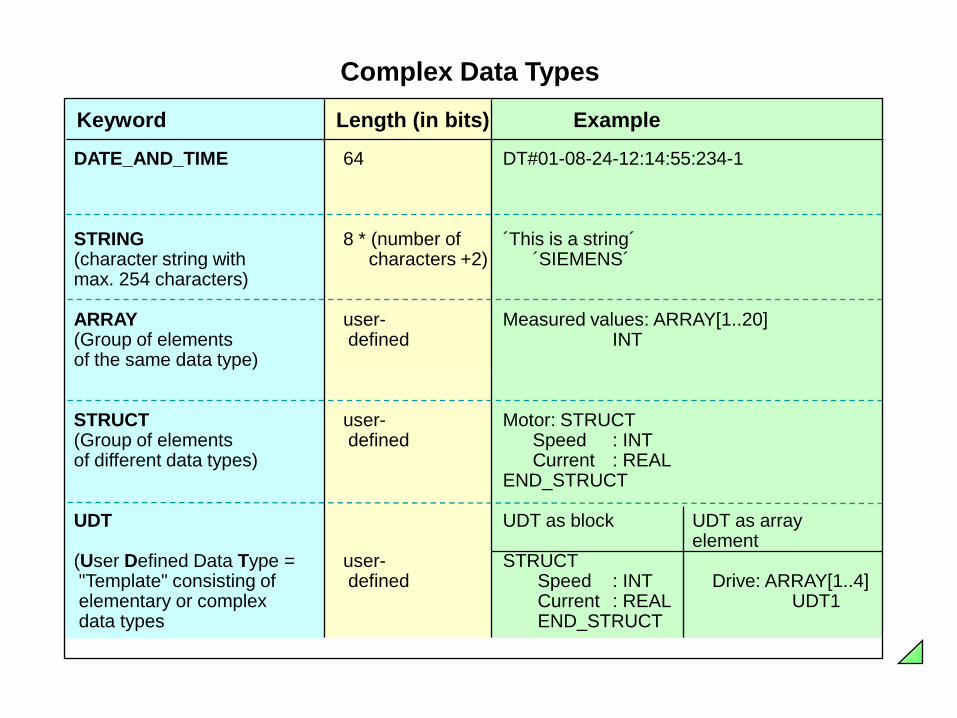
Complex Data Types
Keyword Length (in bits) Example
DATE_AND_TIME 64 DT#01-08-24-12:14:55:234-1
STRING 8 * (number of ´This is a string´(character string with characters +2) ´SIEMENS´max. 254 characters)
ARRAY user- Measured values: ARRAY[1..20](Group of elements defined INT of the same data type)
STRUCT user- Motor: STRUCT(Group of elements defined Speed : INTof different data types) Current : REAL
END_STRUCT
UDT UDT as block UDT as array element
(User Defined Data Type = user- STRUCT "Template" consisting of defined Speed : INT Drive: ARRAY[1..4]elementary or complex Current : REAL UDT1 data types END_STRUCT

0.0 Start BOOL0.1 Stop BOOL2.0 Motor_on BOOL4.0 Speed INT
DB 5
FB 5
in Start BOOLin Stop BOOLout Motor_On BOOLout Speed INTstat ...Temp...
...A #StartAN #Stop= #Motor_on...
Drive
Function FC10
in On_1 BOOLin On_2 BOOLout Off BOOL...
...A #On_1A #On_2= #Off...
CALL FB5, DB5Start :=I 0.0Stop :=I 0.1Motor_on :=Q8.0Speed :=QW12
Programexecution
CALL FC 10On_1 := I 0.1On_2 := I 0.2Off := Q8.0
Functions and Function Blocks (1)

Exercise X of day 7

Summary of day 7