Optical response of a misaligned and suspended Fabry-Perot cavity
14
arXiv:quant-ph/0512252v1 29 Dec 2005 Optical response of a misaligned and suspended Fabry-Perot cavity G. Cella 1 , A. Di Virgilio 1 , P. La Penna 1,2 1 INFN, sez. Pisa 2 EGO European Gravitational Observatory V. D’Auria 1 , A. Porzio 2,3 , I. Ricciardi 1,4 , S. Solimeno 1,3,4 1 Dip. Scienze Fisiche, Univ. Federico II 2 ”Coherentia”, CNR–INFM, Napoli 3 CNISM, Unit´a di Napoli 4 INFN, sez. Napoli (Dated: February 1, 2008) The response to a probe laser beam of a suspended, misaligned and detuned optical cavity is examined. A five degree of freedom model of the fluctuations of the longitudinal and transverse mirror coordinates is presented. Classical and quantum mechanical effects of radiation pressure are studied with the help of the optical stiffness coefficients and the signals provided by an FM sideband technique and a quadrant detector, for generic values of the product τ of the fluctuation frequency times the cavity round trip. A simplified version is presented for the case of small misalignments. Mechanical stability, mirror position entanglement and ponderomotive squeezing are accommodated in this model. Numerical plots refer to cavities under test at the so-called Pisa LF facility. I. INTRODUCTION AND NOTATION Optical cavities are generally studied by assuming a single mode excitation and ignoring the photon scatter- ing by mirror reflections into other modes. A single mode description is no more reliable when a slight misalignment is sufficient to excite different modes. This situation is met in almost concentric or plane–parallel or confocal configurations. In other cases the weak amplitudes of modes falling outside the resonance bandwidth are of in- terest. For example, the sensitivity of interferometers with cavities placed in their arms depends on the contri- bution of higher modes as well as the error signals used for longitudinal and angular alignments. Optical cavities are generally stabilized, in length, by the Drever-Pound (D-P) technique [1] working with odd harmonics of the phase modulated laser beam. In order to deal with a large variety of situations the model discussed in this paper accounts for misalignment, detuning and a generic spectrum of harmonics. Faced with the possibility of working with approximate expres- sions it has been preferred to simplify exact solutions at the end of the calculation. This option avoids difficulty of making adequate approximations in presence of a large number of parameters. This strategy can be useful for the design studies nec- essary for the development of future gravitational anten- nas. It gives the possibility to investigate noise contri- butions coming from all optical and mechanical degrees of freedom. It can be also used for studying instabilities, optical spring effect, entanglement and radiative pressure squeezing associated to both axial and angular fluctua- tions for any degree of detuning, misalignment and mis- match. The present work grew up from the study of short and large spot size resonators [2] implemented at LFF (Low Frequency Facility [3]) a facility dedicated to test- ing new mechanical suspensions, controls and mirrors for the VIRGO interferometric gravitational antenna, and studying the effects of radiation pressure, mirror and sus- pensions thermal noise. Main features of the LFF are the use of suspended mirrors and the possibility of confining large section cav- ity modes. The mirrors hang from multipendula which guarantee a drastic reduction of the seismic noise above the resonance frequencies of the mechanical modes. The phase-modulated light reflected by the cavity is used by a Pound-Drever apparatus [1] both for stabilizing the cav- ity length, and measuring the noise spectrum. Several papers analyzed the dynamic and the alignment of cav- ities sharing some of the LFF features [4, 5, 6]. Numer- ous specialized studies have been produced by research groups of VIRGO, LIGO, TAMA and GEO projects [7]. Suspended cavities have been analyzed by several au- thors in different contexts, all sharing the common fea- ture of using a system of Langevin equations for both the mechanical and electromagnetic modes. The coupling of cavity and mechanical modes is represented by suitable potentials [8, 9] leading to a complex interplay between cavity mode amplitudes, mirror positions and orientation fluctuations. In this paper the resonator is regarded as a mechanical Langevin system driven by thermal sources and shot noise. This is done by-passing the Hamiltonian approach and hiding the optical modes fluctuations into the mechanical ones by generalizing an approach intro- duced in [10]. So doing, the Langevin system contains ponderomotive terms, connected with the classical part of the laser beam and the shot noise. The seismic noise af- fecting the mechanical system has been neglected. Once known, its local spectral density can be easily added to the thermal one. Thermal motion of mechanical oscillators has been modelled as standard Brownian motion [11], possibly cor- rected by Diosi for preserving the quantum mechanical
Transcript of Optical response of a misaligned and suspended Fabry-Perot cavity
arX
iv:q
uant
-ph/
0512
252v
1 2
9 D
ec 2
005
Optical response of a misaligned and suspended Fabry-Perot cavity
G. Cella1, A. Di Virgilio1, P. La Penna1,2
1 INFN, sez. Pisa2 EGO European Gravitational Observatory
V. D’Auria1, A. Porzio2,3, I. Ricciardi1,4, S. Solimeno1,3,4
1 Dip. Scienze Fisiche, Univ. Federico II2 ”Coherentia”, CNR–INFM, Napoli
3 CNISM, Unita di Napoli4 INFN, sez. Napoli
(Dated: February 1, 2008)
The response to a probe laser beam of a suspended, misaligned and detuned optical cavity isexamined. A five degree of freedom model of the fluctuations of the longitudinal and transversemirror coordinates is presented. Classical and quantum mechanical effects of radiation pressure arestudied with the help of the optical stiffness coefficients and the signals provided by an FM sidebandtechnique and a quadrant detector, for generic values of the product τ of the fluctuation frequencytimes the cavity round trip. A simplified version is presented for the case of small misalignments.Mechanical stability, mirror position entanglement and ponderomotive squeezing are accommodatedin this model. Numerical plots refer to cavities under test at the so-called Pisa LF facility.
I. INTRODUCTION AND NOTATION
Optical cavities are generally studied by assuming asingle mode excitation and ignoring the photon scatter-ing by mirror reflections into other modes. A single modedescription is no more reliable when a slight misalignmentis sufficient to excite different modes. This situation ismet in almost concentric or plane–parallel or confocalconfigurations. In other cases the weak amplitudes ofmodes falling outside the resonance bandwidth are of in-terest. For example, the sensitivity of interferometerswith cavities placed in their arms depends on the contri-bution of higher modes as well as the error signals usedfor longitudinal and angular alignments.
Optical cavities are generally stabilized, in length, bythe Drever-Pound (D-P) technique [1] working with oddharmonics of the phase modulated laser beam.
In order to deal with a large variety of situations themodel discussed in this paper accounts for misalignment,detuning and a generic spectrum of harmonics. Facedwith the possibility of working with approximate expres-sions it has been preferred to simplify exact solutions atthe end of the calculation. This option avoids difficultyof making adequate approximations in presence of a largenumber of parameters.
This strategy can be useful for the design studies nec-essary for the development of future gravitational anten-nas. It gives the possibility to investigate noise contri-butions coming from all optical and mechanical degreesof freedom. It can be also used for studying instabilities,optical spring effect, entanglement and radiative pressuresqueezing associated to both axial and angular fluctua-tions for any degree of detuning, misalignment and mis-match.
The present work grew up from the study of shortand large spot size resonators [2] implemented at LFF(Low Frequency Facility [3]) a facility dedicated to test-
ing new mechanical suspensions, controls and mirrors forthe VIRGO interferometric gravitational antenna, andstudying the effects of radiation pressure, mirror and sus-pensions thermal noise.
Main features of the LFF are the use of suspendedmirrors and the possibility of confining large section cav-ity modes. The mirrors hang from multipendula whichguarantee a drastic reduction of the seismic noise abovethe resonance frequencies of the mechanical modes. Thephase-modulated light reflected by the cavity is used by aPound-Drever apparatus [1] both for stabilizing the cav-ity length, and measuring the noise spectrum. Severalpapers analyzed the dynamic and the alignment of cav-ities sharing some of the LFF features [4, 5, 6]. Numer-ous specialized studies have been produced by researchgroups of VIRGO, LIGO, TAMA and GEO projects [7].
Suspended cavities have been analyzed by several au-thors in different contexts, all sharing the common fea-ture of using a system of Langevin equations for both themechanical and electromagnetic modes. The coupling ofcavity and mechanical modes is represented by suitablepotentials [8, 9] leading to a complex interplay betweencavity mode amplitudes, mirror positions and orientationfluctuations. In this paper the resonator is regarded asa mechanical Langevin system driven by thermal sourcesand shot noise. This is done by-passing the Hamiltonianapproach and hiding the optical modes fluctuations intothe mechanical ones by generalizing an approach intro-duced in [10]. So doing, the Langevin system containsponderomotive terms, connected with the classical partof the laser beam and the shot noise. The seismic noise af-fecting the mechanical system has been neglected. Onceknown, its local spectral density can be easily added tothe thermal one.
Thermal motion of mechanical oscillators has beenmodelled as standard Brownian motion [11], possibly cor-rected by Diosi for preserving the quantum mechanical

2
FIG. 1: Typical optical layout of the apparatus examinedin the present paper. The laser beam is phase modulated atfrequency Λ by the modulator M (Λ). The modulated bemadrives the cavity. The front M1 and back M2 mirrors aresuspended to multipendulum chains. The beam reflected bythe front mirror is sent to a photodetector PD, and the pho-todetection signal is demodulated before going to a spectrumanalyzer. The same signal is sent to a control system (notshown) which provides a feedback signal applied to mirrorM1. The noise of the system is studied by spectral analysis.
commutation relations [12], or by non-Lindblad masterequations (ME) [13, 14]. Accordingly, in the presentmodel different thermal correlation functions have beenintroduced.
The quantum field fluctuations (shot-noise) are ac-counted for by splitting each mode amplitude in a classi-cal and a quantum parts [9, 15] and relying on the input-output theory [16].
Radiation pressure can lead to mechanical instabilities,as predicted by Braginsky and Manukin [17]. Acting onthe suspended mirrors it provides a spring action whicheither depresses or reinforces any perturbation [10, 18,19, 20]. It may also be used to mechanically entanglethe two mirrors [21] or to enhance the squeezing of theoutput field [22].
In Fig.1 it is represented the typical optical layout ofthe apparatus that will be examined. Main features ofthe present model are: i) the multimode description ofthe cavity field; ii) the inclusion of radiation pressure andshot noise terms; iii) the description of suspensions andmirrors in terms of mechanical modes.
Here and in the following J = 1, 2 labels the mirror,x the axial and q = y, z the transverse coordinates. Theanalysis is focused on the fluctuations of the J ’s mirrororientation (δθJq) and displacements (δxJ , δεJq), com-bined in the parameters
δψJ = (−1)J
2kℓδxJ
δαJq = i (−1)J√
2kℓwJ
(δθJq −
δεJqRJ
)(1)
with kℓ laser wavenumber, wJ spot size, RJ mirror cur-
vature radius and δθJq = (δ~ΩJ × x) · ~q depending on the
rotation’s angles δ~ΩJ . In addition the mirror vibrationsare accounted for by introducing matrices ςJs and func-tions δςJs representing respectively profile and amplitudeof the s-th vibrational mode of the J–th mirror.
The radiation pressure force and torques are linearizedwith respect to the set δαJq of transverse mirrorcoordinates by introducing optical stiffness coefficients.Hence, the Fourier transforms δαJq satisfy Langevinequations with driving forces proportional to these quan-tities. They become important in proximity of the sus-pensions and mirror mechanical resonances. These stiff-ness coefficients are in general frequency dependent forthe presence of the phase factor eiτ , with τ the cavityround trip.
A vector approach has been adopted by representingthe amplitudes of the excited cavity modes by a columnvector a while the mismatch and misalignment of theinput beam is accounted for by a vector v. The vari-ous quantities O used for describing the system dynamics(e.g. the force acting on a given suspension mode) havebeen expressed in forms like O = v† · O · v with O amatrix representation of the quantity itself. In analogywith quantum mechanics O is seen as the matrix repre-sentation of an operator O corresponding to the quantityof interest, and v as the quantum state of the resonator.
For evaluating spectral densities it has been introducedthe symbol ‡ which is defined by its action on frequencydependent quantities:
f ‡ () ≡ f∗ (−∗) ,
and the shorthands
ℑf () =1
2i
(f () − f ‡ ()
)
ℜf () =1
2
(f () + f ‡ ()
).
The same ‡ applied to a frequency dependent matrixtransforms O () into O‡ () = O† (−∗).
The summation symbol is omitted when applied to ex-pressions containing a repeated index.
The paper is organized in seven sections. Section II isdedicated to the optical modes excited in a cavity withmoving mirrors, and to the susceptivities relative to thenoise sources of the suspensions, mirror vibrations andshot noise. The dynamic of the mechanical components(mirrors and suspensions) is discussed in Sec. III whilethe Drever-Pound and quadrant detector signals are an-alyzed in Sec. IV.
The results obtained in these sections are combined inSec. V where a five degrees of freedom model of the cav-ity, including radiative pressure and torques, is presented.The model is linearized for small misalignments and res-onance enhanced effects are discussed in Sec VI wherethe cavity is examined as a bipartite system. In thiscontext ponderomotive squeezing of the output field andentanglement of two mirror modes are discussed. Themanuscript is completed by six mathematical appendices.

3
The first three of them give the expressions for the stiff-ness and the Drever-Pound signal matrices together withtheir simplified expressions in case of small misalignmentand mismatch. The last ones are dedicated to thermaland shot-noise sources, and their mutual correlations.
II. CAVITY FIELD
A suspended cavity of length L excited by a time har-monic field is described by a superposition of Hermite-Gauss modes uλ (~r, x)
e−iωℓt
∑
σ=±exp
[iσkℓ
r2
2R(x)
]a(σ)λ (x, t) uλ (~r, x) .
with ωℓ the laser frequency, σ = + for a wave travel-ling from mirror 1 toward 2 and − contrariwise. Thewavefront curvature R(x) is matched to the mirror’s cur-vature: R (0) = R1 < 0, R (L) = R2 > 0. Eachmode is labeled as usual by a couple of integer num-bers (λy , λz) ≡ λ. Here and in the following x stands forthe optical axis coordinate and (y, z) ≡ ~r are the twotransverse ones. Each mode uλ is taken with a fixed nor-malization on the transverse section and without phasefactors,
uλ(~r) = uλy(y)uλz
(z) ,
while the amplitudes are written as
a(σ)λ (x, t) = eiσ[k
ℓx−(λy+λz+1)φ(x)]∣∣∣a(σ)λ (x, t)
∣∣∣
where φ (x) = arctan(x−x0
b
)is the phase delay of the
Gaussian fundamental mode with respect to a planewave, x0 being the distance of the waist from the in-put mirror and b the confocal parameter. The field ispropagated outside the resonator by passing through thedifferent optical components met on the way toward thelaser source and the photodetector which provides theerror signal.
The laser beam incident on (input) mirror 1 has beensplit it in a classical and in a quantum term:
Ein (~r, t) = e−iωℓtE
(1 + µℓ (t)
)uin (~r) + δaSN (2)
being
E =
√P
~ωℓ= 2.5 × 10⁹
(P
1W
)1/2 (λℓ
1µ
)1/2
Hz1/2
the mean amplitude, and µℓ the relative amplitude fluc-tuations. Effects of the laser linewidths have been ig-nored.
Misalignment and mismatch effects between the inputbeam and the cavity are taken into account by writinguin (~r) as a superposition of cavity modes, namely
uin (~r) = vλ uλ (~r) . (3)
The structure of the expansion coefficients is factorizedin a product of Hermite polynomials
vλ ∝δyδzHλy
(vy
δ2y−1
δy
√2
)Hλz
(vz
δ2z−1
δz
√2
)
√2λy+λzλy!λz !
(4)
depending on the misalignment vq and mismatch δq pa-rameters defined respectively by
vq = −ikℓw1√2
(θq −
εqQq
)
δq =
√1 + i
2
kℓw21
QqQ∗1
(Qq −Q∗1).
For a perfect matching v = 0 and δ = 0. Here Q1 is thecomplex curvature radius of the cavity mode evaluatedat the input mirror, while Qq, θq and εq stand for thecurvature radius, angular and transverse misalignmentof the input beam.
The modal expansion (3) will be used in the followingfor representing the cavity fields in correspondence of thetwo mirrors as column vectors v with components vλ. Sodoing the multiplication of u (~r) by a function w (~r) willbe represented by the product w · v of v by a matrix w.
The coupling of the cavity with the universe modesthrough the partially transmitting mirrors introduces thequantum noise contribution δaSN (r,t) of Eq. (2)
[δaSN (r,t) , δaSN† (r′,t′)
]= δ(3) (r− r′) δ (t− t′)
It can be expanded as a superposition of delta-correlatedoperators δaSNλ (t),
δaSN (r,t) = δaSNλ (t)uλ (r) . (5)
Before arriving at the mirror the excitation beam ispassed through a phase modulator represented by thephase factor
F = eiM sin(Λt) = e−ipΛtJp (M) (6)
with Jp (M) the p-th Bessel function of argument M .The input modulation F modifies the laser excited am-plitude aℓλ into a sum of harmonics varying on the timescale of the suspension fluctuations,
aλ = Jpe−ipΛtaλp (7)
while leaving the noise unaffected.
A. Cavity fluctuations
Owing to the fluctuations of the suspensions the mirrororientations change slowly in time by undergoing torsionsδΩJz (t), tiltings δΩJy (t) and transverse displacementsδ~εJ (t). The mirror can rotate also around the opticalaxis, but this motion is uncoupled to the cavity field inthe linear approximation.

4
The mirror motions separate into fluctuating and av-erage components, the latter ones setting the referenceframe for the vector representation. So doing the aver-age misalignment and displacements will be included inthose relative to the input beam, which will be repre-sented by a unit amplitude vector vJ
v1 = v , v2 = Φ1
2 · v
with Φ a diagonal matrix of components Φλ =e−i2(λy+λz+1)φG and φG = φ (L) − φ (0) the single-tripphase delay of the Gaussian fundamental mode. Accord-ingly in the following the parameters δαJq (see Eq. (1)will be small fluctuating quantities.
The reflection at mirror 1 induces the transformationuλa
(−)λ = r1uλa
(+)λ with r1 (t) the phase factor
r1 = r1 exp
[−ikℓ δε
21
R1− i2kℓδx1 − i2kℓδuDEF1 + i2kℓ
(δ~Ω1 × x− δ~ε1
R1
)· ~r
]. (8)
Here δx1 (t) is the deviation of the center from the po-sitions at rest (x1 (t) = 0 + δx1 (t)). δuDEF1 (~r, t) is thetiny deformation of the mirror surface represented by thematrix δ ς1 (t) of components
δς1λλ′ (t) = 2kℓ∫uλ (~r) δuDEF1 (~r, t)uλ′ (~r) d2~r (9)
Expanding further δuDEF1 into mirror modes [23, 24]δς1 (t) becomes a superposition
δς1 (t) = δς1s (t) ς1s (10)
of matrices ς1s times fluctuating amplitudes δς1s (t)driven by radiation pressure and thermal noise.
Although the frequencies of the mirror acoustic modesare very large, the tails of their spectra contribute to thelow frequency thermal noise of the interferometers as re-cently reported by [25]. Levin [26] has approximated,at very low frequency, the many mode profiles with thesteady-state mirror surface deformation δuDEF1 (~r) (inmatrix form ςL1 ) under the action of the incident beam(positive for a compression), by replacing Eq.(10) with
δς1 (t) = ςL1 δςL1 (t) (11)
δςL1 (t) being a stochastic process, (see Eq.(43)).
Accordingly, ignoring the quadratic expressionkℓδε21/R1 the phase factor r1 (Eq.(8)) is represented invector form by
r1e−i(2kℓδx1+δς1) · D1 (−δα1) (12)
with δα1 = (δα1y, δα1z) the combination of rotation anddisplacement defined by Eq.(1) and D1 the displacementoperator
D1 (−δα1) = exp(−δα1qB
†q + δα∗
1qBq
)
acting on the functions of the transverse coordinates.The operators By and Bz act on the mode functions uλas typical annihilation operators, Bun =
√nun−1, and
this is the reason why D has been called a displacementoperator.
Next, the propagation from the input mirror to theopposite one is described by
eikℓL
(DtΦ
) 1
2
(13)
with Dt = e−τddt the delay operator by the cavity round-
trip time τ . Next combining (12) with (13) a round tripis represented by
Re−iψ−iδψ1,cav
(DtΦ
) 1
2 · e−iδς2 · D2 (−δα2)(DtΦ
) 1
2 · e−iδς1 ·D1 (−δα1)
where ψ is the detuning phase (ψ > 0 for a cavity shorterthan the closest resonance length), R = r1r2 = e−F/π
with F the cavity finesse, and δψ1,cav the accumulatedphase shift, positive for decreasing cavity length,
δψ1,cav (t) = δψ1 (t− τ) + δψ2
(t− τ
2
)
with δψJ = − (−1)J
2kℓδxJ . Next, in view of the small-
ness of δψ1,cav, δαJ and δςJ D1,2 and e−iδψ1,cav can belinearized thus obtaining for the round-trip transforma-tion
e−iψRΦ(Dt − iX · δαJ,cav − iδςJ,cav
). (14)
Here X · δαJ,cav indicates the sum Xi (δαJ,cav)iand two

5
vectors
X =(1,Xy,Xz,Yy,Yz
)(15)
δαJ,cav =(δψJ,cav, δα
′′Jy,cav, δα
′′Jz,cav, δα
′Jy,cav, δα
′Jz,cav
)
collect the phase quadratures Xq = Bq + B†q, Yq =
i(Bq − B†
q
)and the combinations
δα1q,cav (t) = δα1q (t− τ) + eiφGδα2q
(t− τ
2
)
(α′ and α′′ are the real and imaginary part of α respec-tively).
Analogously for δςJ,cav
δς1,cav (t) = ςJsδςJs (t− τ)+Φ− 1
2 · ς2s′ ·Φ1
2 δς2s′(t− τ
2
)
The amplitude a(σ)λyλz
(t) of the λyλz-th mode is prop-
agated back and forth the cavity. The fraction t1 is in-jected into the Fabry Perot through mirror 1 at time t,propagates toward and is reflected by mirror 2 at t + τ
2and again by 1 at t. Hence, summing over the sequenceof rund-trips, the field aJ incident on the J-th mirrorreads
aJ = E(1 + µℓ
)GJ ·vJF + δaSN (16)
with E = t1E and
GJ =1
1 −Re−iψΦ·(Dt − iX · δαJ,cav − iδςJ,cav
)
For very small δαJ,cav and δ ςJ,cav first-order pertur-bation theory can be used. On the other hand assumingfor uλ either Hermite or Laguerre-Gauss modes the var-ious terms of the perturbation X · δαJ,cav + δςJ,cav donot couple the respective degenerate modes. Hence, theGreen operator GJ can be expressed as
GJ ≃ G−iG · δαJ,cav−iδGDEF (17)
where the first term on the right is a static propagator,the second the contribution of the linearized motion ofthe mirrors and the third one describes the mirror defor-mations,
G =(1 −Re−iψDtΦ
)−1
G = e−iψRG ·Φ·X · GδGDEF = e−iψRG ·Φ·δςJ,cav · G (18)
Next, the contributions of the shot noises entering thecavity through mirror J has been split as δaSN = δaSN1 +t2t
−11 δaSN2 , so that the same approximation of Eq. (18)
applies and
aJ = a0,J + δaJ + δaSN (19)
Here δaJ is fluctuating with the cavity geometry andlaser intensity, while a0,J does not depend on it and onshot noise,
a0,J ≈ EG · vJFδaJ ≈ E
(µℓG−iG · δαJ,cav−iδGDEF
)·vJF
δaSN = t1G·(δaSN1 +
t2t1δaSN2
). (20)
Further, the relation Dte−ipΛt = e−ipΛteipΛτ Dt im-
plies Ge−ipΛt = e−ipΛtGp with the suffix p indicatingthat R has been replaced by Rp = eipΛτR. Then, thefactor e−ipΛt contained in the function F (see Eq. 6) canbe displaced from the right to the left side of the aboveexpressions by adding the suffix p to the various Green’sfunctions. Hence
aJ = e−ipΛt (a0,Jp + δaJp) + δaSN
where
a0,Jp = EJpGp·vJ (21)
δaJp = e−ipΛtEJp(µℓGp − iGp · δαJ,cav−iδGDEF
p
)·vJ
Analogously for the output field [16]
aOUT0,Jp = t1EJpGOUTp ·v1
δaOUTJp = t1EJp(GOUTp µℓ − iGp · δα1,cav
−iδGDEFp
)·v1
δaOUT SN = t21
(GOUT ·δaSN1 +
t2t1
G·δaSN2
)(22)
where GOUT = G− r1/t21.
III. RADIATION PRESSURE AND TORQUE
Bouncing back and forth the two mirrors the laser andshot noise fields exert a radiation pressure resulting in anaxial force directed along the optic axis x and a torqueparallel to their surfaces, proportional to the total inten-
sity a†J ·aJ and moments a
†J · Xq · aJ . They split into
classical FJ rp, TJ rp and quantum FSNrp , T SN
J rp compo-nents respectively given by
FJ rp = (−1)J E2 2RJ ~kℓ (F0,J + δFJ ) x (23)
TJ rp = (−1)J E2 2RJ ~kℓwJ√
2(T0,Jq + δTJq) q × x
and
FSNJ rp ≡ (−1)J E 2RJ ~kℓXSN
Jψ x
T SNJ rp ≡ (−1)
J E 2RJ ~kℓwJ√
2XSNJθq q × x (24)
where RJ = |rJ |2 + 12AJ with AJ the J–th mirror power
absorption.

6
F0,J and δFJ indicate the contributions of a†0,J ·a0,J
and a†0,J · δaJ + H.c. and analogously for T0,Jq, δTJq.
F0,J , T0,Jq split in turn into time constant terms F0,T0,Jq, balanced by the stabilization system of the appara-tus, and small terms δF0,J , δT0,Jq oscillating at multiplesof Λ. Being Λ typically of the order of some MHz thesecontributions can be ignored.
For a stabilized resonator GJ is represented as in (17)so that δFJ and δTJq reduce in the frequency domainrespectively to
δFJ = F0,J µℓ + FJ · δαJ,cav + δFDEFJ,cav
δTJq = T0,Jqµℓ + TJq · δαJ,cav + δTDEFJq,cav (25)
The three pieces of Eqs. (25) represent, in the given or-der, the contributions of the fluctuation of laser intensity,mirror displacements, rotations and surface deformationsto the radiation pressure forces and torques.
Being the suspension characteristic frequencies gener-ally smaller than the mirror modes resonances [24], thedeformations are described by a single matrix (see Eq.(11)).
The vectors FJ = (FJψ , FJXq, FJY q) and TJq =(TJψq, TJqXq′ , TJqY q′ ) contain five proportionality con-stants between the forces (the torques) and the coordi-nates (δαJ,cav) which parametrize the mirror’s displace-
ment, so they are stiffness coefficients. F0,J , FJ , δFDEFJ,cav
and T0,Jq, TJq, δTDEFJq,cav depend on the steady-state am-
plitudes of the cavity modes, represented by the vectorvJ ,
O0,J = v†J · O0 · vJ
OJ = v†J · O · vJ (26)
with O0,J = F0,J , T0,Jq and O = FJ , δFDEFJ,cav , TJq and
δTDEFJq,cav Matrices F0, δFDEFJ,cav and T0,q, δT
DEFJq,cav are re-
ported in Appendix A (Eqs. (A1,A4) ) while F, Tq arecollections of five matrices (Eq. (A2)). They depend onGreen’s matrices (Eqs. (A3,A5)), and through them onfrequency and detuning, closeness of cavity modes withrespect to linewidth and phase modulation depth. Thefrequency dependence is due to the factor eiτ appearingin different fashions in Gp, GOUT
p , Gp.Eventually, the shot-noise contributions (Eq. (24)) are
expressed by
XSNJi = t−1
1 Jpv†J · G†
p·Xi · δaSNeipΛt +H.c.
with i ∈ (ψ, θy, θz) and take in the frequency domain theform
XSNJi = t−1
1 2Jpℜv†J ·G†
p·Xi · δaSNp
(27)
Finally, on the J ’s mirror mode act the forces,
FDEFJs rp = (−1)
J E2 2RJ ~kℓ
(FDEF0,Js + δFDEFJs,cav
)x
FDEF SNJs rp ≡ (−1)
J E 2RJ~kℓXDEF SNJs x (28)
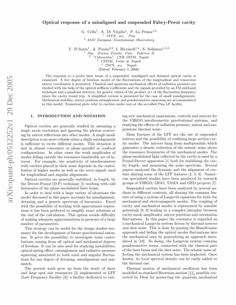
FIG. 2: Axial Fψ, F1Xy , F1Xz F1Y y and angular T1zXy,T1zXz, T1zY y , T1zY z stiffness coefficients vs. length L of asymmetric cavity for angular misalignments θy = .01,θz = .1mrad and detunings ψ = .1, .2, .3 π/F . The round-trip phasefactor eiτ has been ignored.
where
δFDEFJs,cav = eiτ FDEFJsJs′δςJs′ + eiτ/2FDEFJsJs′δςJs′ .
Here
FDEFJsJ′s′ = v†J · FDEFJsJ′s′ · vJ (29)
is the force acting on the Js-mode due to the deforma-tions of the mirror surfaces. In this case the force doesnot factorize as for the suspension modes. FDEFJsJ′s′ (Eq.(A6)) represent the effects of the vibrations of the modesJ ′s′ on the Js one.
Next, the shot-noise force is given by
XDEF SNJs = t−1
1 2Jpℜv†J ·G†
p·ςJs · δaSNp
(30)
In Fig. 2 the optically induced stiffness coefficientshave been plotted for a set of detunings and angular mis-alignments, in an almost concentric cavity having a fi-nesse F = 500 and output spot sizes of 2 × 10⁻³m. Be-ing close to the concentric configuration also the stiffnesscoefficients FX/Y q, TzXy, TyY z become comparable with
Fψ, TJqX/Y q for cavity axis misaligned by θy = 10−2 rad,
θz = 10−1 rad. The signs of the stiffness coefficients mayhave important consequences on the mechanical stabil-ity, as discussed by several authors for plane-parallel andconcave mirrors [10, 18].

7
A. Small misalignment and mismatch
In the limit of small misalignment and mis-match the vector v1 (Eq. (4)) reduces to ≃1+δv = 1, (δvy , δvz) , 0, ..., 0 with
δvq = −√
2
w1
Q∗QqQ∗ −Qq
(θq −
εqR1
)
For mirror 2 vq is multiplied by e−iφG . Splitting forcesand torques in 0-th and 1-st order terms in these mis-alignment parameters δFJ and δTJq of Eqs. (25) takethe simpler forms,
δFJ = δF(0)J + δF
(1)J
δTJq = δT(0)Jq + δT
(1)Jq (31)
where
δF(0)J = F0,J µ
ℓ + FψδψJ,cav + δFDEFJ,cav
δF(1)J = δFJXqδα
′′Jq,cav + δFJY qδα
′Jq,cav
δT(0)Jq = TXδα
′′Jq,cav + TY δα
′Jq,cav
δT(1)Jq = δTJqδψJ,cav
with
δFJX/Y q = 2 ReFX/Y vJq
δTJq = 2 ReT
(1)ψ vJq
FX/Y , Tψ being defined in Appendix C. Accordingly, inthe ideal setting of the cavity the forces and torquesare respectively proportional to longitudinal δψJ,cav andtransverse δα′′
Jq,cav fluctuations through the stiffness co-
efficients Fψ, TX/Y . A slight deviation from it introducesforces and torques with a reverse dependence on fluctu-
ations, say δF(1)J , δT
(1)Jq depend respectively on δαJq,cav
and δψJ,cav.
IV. ERROR SIGNALS
The errors used for controlling the cavity are providedby Drever-Pound (DP) and quadrant detector signals(QD). In the DP detection technique the photodetectorcurrent I (t), obtained from the light transmitted andreflected by the input mirror, is mixed with a local os-cillator ∼ sin (kΛt+ ϕ) with positive odd integer k andlow-pass filtered by an averaging procedure
sDP (t) =
∫ t
−∞KDP (t− t′) sin (kΛt′ + ϕ) I (t′) dt′ (32)
with the filter response KDP (t− t′) extended to a suit-
able interval much longer than (kΛ)−1
, and short com-pared to the time scale of the phase-quadrature fluctua-tions. Tuning ϕ around 0 sDP can be maximized for amisaligned cavity.
FIG. 3: Drever-Pound static characteristics s vs. ψ for cav-ity lengths 1 ÷ 10 cm and ϕ = 0. The plots correspond tomodulation frequency Λ = 2cλℓ/
(πw2
), depth M = 0.1, and
jaw angle δθz = 0.01.
Putting δaSNp = δaSN ( + pΛ), sDP is represented inthe frequency domain by
sDP /KDP = E2(sDP µℓ + sDP · δαcav + δsDP DEF
)
+EXDP SN (33)
where
sDP = v†1 · IDP · v1
sDP = v†1 ·
(IDP+ − IDP−
)· v1
δsDP DEF = v†1 ·
(δIDP DEF
+ − δIDP DEF−
)· v1
XDP SN = XDP SN+ − XDP SN
−
with IDP , δIDP DEF± , IDP± , XDP SN
± defined in Ap-pendix B.
In Figure 3 the static characteristic sDP versus ψ hasbeen plotted for a set of cavity lengths and modulations.
Figure 4 contains plots of the coefficients sψ and sXyvs. cavity length for ϕ = 0, θz = .1 mrad and 7 de-tunings. They show that as a consequence of the mis-alignment sXy becomes comparable to sψ, so that theD-P error signal contains contributions of the torsionalfluctuations around the vertical axis.
At low frequency δsDP DEF becomes proportional tothe thermal noises δςL TH .
The quadrant detector used for stabilizing the angularoscillations provides two error signals sQDq (t) (q = y, z),proportional to expressions similar to (32) with the cur-rent I replaced by Iq = β† ·Qq · β with
β = e−ipΛtaOUTp + δaOUT SN ,
the matrix Qq representing the function sgn (q). Then,sQDq is given by an expression similar to (33) with GOUT†
p
replaced by GOUT†p ·Qq.
A. Small misalignment and mismatch
In the limit of small misalignment and mismatch thesignal can be split into zeroth- and first-order contribu-tions
sDP = s(0) + δs(1)

8
1x10⁵
3x10⁵
1x10⁵
5x10⁴
sy
sXy
5 10L (cm)
FIG. 4: Coefficients sψ and sXy vs. cavity length for ϕ = 0,θz = .1 mrad and 7 detunings ranging in the interval −.3 π
F≤
ψ ≤ .3 πF
.
given respectively by (Eqs. (C4))
s(0)/KDP = E2(sψµ
ℓ + sψδψ1,cav + δs(0) DEF)
+EXSN (0)
δs(1)/KDP = E2(δsXqδα
′′1q,cav + δsY qδα
′1q,cav
+δs(1) DEF)
+ EδXSN (1) (34)
with δsX/Y q = 2ResX/Y v1q
and sX/Y defined in Ap-
pendix C.For a perfectly aligned and matched cavity the D-P sig-
nal is sensitive to the axial fluctuations δψ1,cav, mirror
deformation term δs(0) DEF and shot noise XSN (0). Inparticular, a contribution δψ1,cav depending on the mir-ror thermal noise δςL1,2 is added to the length fluctuation.A deviation from alignment introduces in the error signalcontributions proportional to the transverse fluctuations.
V. 3D MODEL
The deviations of each mirror from the reference posi-tion is described by the displacements δx, δεy and δεz ofits vertex and the angular parameters δθz = −δΩy andδθy = δΩz. As said δΩq describes a right-handed rota-tions around the axis ”q”, so that δθz is a left-handed tiltand δθy a right-handed torsion. These quantities fluctu-ate as a consequence of suspension thermal fluctuationsand mirror surface deformations. The radiation pressurefluctuations are transferred to the mirrors proportionallywith the laser intensity. The cavity reacts by changesof geometry which in turn changes the stored field andcloses the loop of the cavity-field system.
From a purely-mechanical point of view if the design isgood (that is, symmetric enough) the suspension massesare aligned along the vertical axis z, perpendicular tothe cavity axis x. In these conditions the torsion δθyand vertical δεz degrees of freedom are uncoupled. Acoupling between longitudinal motion δx and tilt δθz isgenerally speaking unavoidable. This is true also for thetransverse displacement δεy which is coupled with therotation around the optical axis. It goes without sayingthat in a real situation it is very difficult to avoid moregeneral cross couplings.
Radiation pressure can increase or reduce existing cou-plings, and it can also produce new ones. While δεq isinsensitive to radiation pressure, δθq responds to the ra-diation torque. For this reason when asymmetric opticalmodes are excited the rotations δθq modify the radiationpressure, and ultimately couple δx and tilting, but alsoδx and torsion.
Before proceeding further it is worth replacing the dis-placements δεJq by δψJq = 2kℓδεJq, the angles δθJqby δϑJq =
√2kℓwJδθJq and introducing a new five
component vector δψJ = (δψJ , δψJq, δϑJq) which formswith the cavity mode amplitudes a system of correlatedstochastic processes. It is usually a very good approxima-tion to model the suspension as a set of damped, indepen-dent oscillators coupled to an heat bath. Each oscillatorJλ , labelled by λ, specifying the prevalent character ofthe mode (tilting, torsion, displacements,violin modes),and the mode index , can be parameterized with its effec-tive mass MJλ, pulsation Jλ and damping coefficientγJλ. For rotations MJλ is replaced by the moment ofinertia. These parameters are related to the masses andstiffness constants of the system. The coordinates of themirror can be written as linear combinations of the oscil-lator’s coordinates qn, and this means that each normalmode gives in principle a contribution to the mirror’s mo-tion. By interacting with thermal baths these modes un-dergo Brownian motions by influencing the electromag-netic field, eventually coupling mechanical and radiationpressure fluctuations.
A. Suspension Langevin system
By linearizing the equation of motion of each mirror(J) the horizontal (x and y) and vertical (z) displace-
ments δψJ , torsion δϑJy, tilt δϑJz and rotation around
the cavity axis δϑJx are expressed in terms of the ampli-tudes AJλ of the normal modes as
δψJµ = KJµλAJλ
having indicated by Jµ a generic degree of freedom andby KJµλ the coupling coefficient with the mode Jλ [27].
If the mirror vertex coincides with the center of massof the suspension payload, and the centers of the sus-pended masses are aligned along the vertical z-axis, thesuspension can be easily modeled by considering only the

9
couplings δψJ−δϑJz and δψJy−δϑJx, and assuming thevertical oscillations independent of the other degrees offreedom. Being the amplitudes of the cavity modes in-dependent of the rotations δϑJx, the suspended cavity isdescribed by the collection δψJ of five fluctuating quan-tities, depending linearly on radiation pressure-torques,thermal noise, D-P and quadrant detector error signals,
δψJ = χJψ 8RJ
(E2δFJ + EXSN
J
)
+χJψθz8RJ
(E2δTJz + EXSN
Jθz
)
+X THJψ + δJ1H
DP sDP
δψJy/z = X THJy/z
δϑJz = χJθzψ8RJ
(E2δFJ + EXSN
J
)
+χJθz8RJ
(E2δTJz + EXSN
Jθz
)
+X THJθz + δJ1H
QDz sQDz
δϑJy = χJθy8RJ
(E2δTJy + EXSN
Jθy
)
+X THJθy + δJ1H
QDy sQDy (35)
In case the mirror vertex and/or the centers of the sus-pension wire clampings are displaced from the respectivemass centers, the vertical fluctuations are coupled to theother ones.
The effect of the servo systems acting on the longitudi-nal and angular mirror displacements have been includedby indicating by HDP and HQD
q the respective transferfunctions.
For the mirror vibrations a Langevin equation for eachmode must be considered since their profiles are different(Eq. (30)),
δςJs = 8χJs
(E2δFDEFJs,cav + EXDEF SN
Js
)+ XDEF TH
Js
(36)
Expressing δFJ , δTJq in terms of displacements and ro-tations by introducing the stiffness coefficients, and doingthe same for the error signals sDP , sQDq the above systemcan be reduced to an equivalent one relating the fluctu-ating displacement + rotations to the thermal noise andshot noise sources.
The axial displacement δψJ and tilting δϑJz re-spond to the axial force E2δFJ + EXSN
J and torque(E2δTJz + EXSN
Jθz
)y generated by the laser beam and
the shot noise. By the way they include the contribu-tions of the mirror thermal noise. On the other hand,δϑJy responds to the torque E2δTJy + EXSN
Jθy. The links
between force-torques and δψJ are represented by thesusceptibilities χJµν .
The terms proportional to E2 and E describe the re-sponse of the system to radiation pressure. Their pres-ence indicates that a motion of the mirrors produces notonly a phase change but also an intensity change provid-ing a spring action.
In writing Eq. (35) the interaction with the mirrornoise was approximated with Eq. (11) while in Eq. (36)the effects of the suspension fluctuations were ignored.Loosely speaking the two systems refer respectively tothe low and high frequency regions. In the former onethe suspensions are mutually coupled by radiative forcesrepresented while the mirror vibrations generate a globalthermal noise hiding the single mode contributions. Inthe latter one the suspensions appear frozen and the mir-ror modes are mutually coupled by radiative forces rep-resented by δFDEFJs,cav.
The solutions of the homogeneous system (35) repre-sent, in absence of feedback forces, free mechanical os-cillations of the suspended cavity, stable or unstable inaccordance with the sign of the imaginary part of theoscillation frequency [20].
For a more detailed analysis (35) and (36) should be
mirrored by the system relative to the quantities δψYJ ,
δςYJ conjugate of δψJ , δςJs , which can be obtainedfrom the above one by replacing χJψ/θq/s by χYJψ/θq/s
(Eq. 40) and XTHJψ/θq, X
DEF THJs by Y THJψ/θq, Y
DEF THJs
(Eq. 41) in the random force expressions.
B. Susceptibilities
The susceptibility χJµν describes the action on the co-ordinate µ of the force/torque acting on ν,
χJµν = KJµλKJνλ χJλ
with χJλ the susceptibility of the mode Jλ of frequencyJλ and damping coefficient γJλ
χJλ =Jλ η
LD 2Jλ
2Jλ −2 − i γJλ
(37)
and KJµλ, KJνλ the coupling coefficients with µ and νmirror coordinates, while the adimensional Lamb-Dickefactor
ηLDJλ = kℓ
√~
2MJλJλ(38)
depends on the mode mass MJλ = MJiK2Jiλ (the subfix
i identifies the i–th mass of the suspension). For rotationsMJλ is replaced by IJλ/w
2J with IJλ the moment of
inertia. Some authors use the so-called optomechanicalcoupling constants GJλ = 2
√2ηLDJλ/τ [21].
The mechanical susceptibility χJs is similar to (37)while the mass appearing in the Lamb-Dicke factor variesfor the different modes, as reported in [24].
C. Thermal contributions
Assuming suspension masses at the same temperatureT, each mode is characterized by a thermal source (see

10
Appendix D)
XTHJλ =
√4kBT
~JλξJλ − i
+ iγJλJλ
√~Jλ
3kBTηJλ (39)
with η, ξ delta correlated random forces introduced byDiosi [12] in order to remove some inconsistencies of theclassical Langevin equation.
A Y-version of (35) can be easily obtained for the Y-quadratures corresponding to the above ones by replacingχJµλ by
χYJλ = i
JλχJλ (40)
and XTHJλ by
Y THJλ =
√4kBT
~JλξJλ − i
Jλ
√~Jλ
3kBTηJλ (41)
The terms proportional to ηJ in Eqs. (39) and (41)can be generally neglected except when the temperatureis rather low and the oscillation frequencies very high, asituation met only in some mirror modes.ηJλ disappears in the simple Brownian motion model
while in Ref. [14] ηJλ has been dropped and√
4kBT~Jλ
ξJλ
replaced by a new delta correlated random noise sourceQJλ.
The thermal sources X THJµ are superpositions
X THJµ = KJµλ χ
THJλ X
THJλ
of the XTHJλ weighted by the thermal susceptivities
χTHJλ = κJλ χJλ (42)
with κJλ = 2√γJλ/η
LDJλ.
The terms of (35) contain contributions proportionalto the fluctuating quantities δςL THJ [26]
δςL THJ =
√4kBT
~
√2~kℓcPφJ ς (43)
with φ the loss angle, ς a delta correlated random forceand cP depending on the illumination profile
P (~r) = Pλy,λze−
r2
2w2 uλy,λz(~r) (44)
For P (~r) differing notably from the Gaussian one thedeformed profile of the mirror δuDEF1,2 can be expressed,neglecting the finite size of the mirrors, by a suitablecombination of derivatives of the deformation δuDEFG (~r)relative to a Gaussian distribution
δuDEF (~r) =∑
λy,λz
Pλy ,λz(−w)
λy+λz∂λy
∂yλy
∂λz
∂zλzδuDEFG (~r)
For a Gaussian illumination cP takes the form
cG =1 − σ2
√2πEwJ
with wJ the spot-size and E,σ the Young’s modulus andPoisson ratio respectively. For a generic illumination cPcan be expressed as cP = fP cG with
fP =∑
λλ′
(−1)λ′
y+λ′
zPλy ,λz
Pλ′
y ,λ′
z
P 200
fλy+λ′
y,λz+λ′
z(45)
fαβ being the αβ coefficient of the expansion of
δuG (~r) e−r2
2w2 in modes uλy,λz(~r).
VI. THE SUSPENDED CAVITY AS A
BIPARTITE SYSTEM
When the frequency is in proximity of two close reso-nances of the mirror 1 and 2 modes, the system behavesas a quantum mechanical bipartite system described byGaussian continuous variables. These systems can formEPR states characterized by their covariance matrix σwhich can be used for evaluating the entanglment of thestate and its content of quantum information.
The difference between the e.m. fields used in quan-tum optics and the present mechanical system concernsthe sources of the respective states. The e.m. fields areproduced by the e.m. vacuum noise entering throughthe mirrors of a cavity containing a nonlinear crystal. Inthe present case thermal and shot noises act as sources.Accordingly, the covariance matrix σ can be split intothermal σTH and shot noise (8E)
2σSN contributions ob-
tained by separating δςJ into δςJ = 8EδςSNJ + δςTHJ sat-isfying the Langevin system (36)
[δςSN/TH1
δςSN/TH2
]=
1
D
[P22 −P12
−P21 P11
]·[χ1X
DEF SN/TH1
χ2XDEF SN/TH2
]
(46)
with PJJ′ factors representing the radiation pressure ef-fects
PJJ = 1 − 8eiτE2 RJ χJ FDEFJJ
PJJ = 8eiτ/2E2 RJ χJ FDEFJJ
and their product D = P11P22 − P12P21. An analogoussystem holds for δςY SN
J with χJ replaced by χYJ .The output field contains a component (Eqs. (18,22))
δaOUT ∝(eiτ Z1δς1 + eiτ/2Z2δς2
)·v1
proportional to δς1,2 through the matrices ZJ =˜G · Φ · ςJ · G and a shot noise GOUT ·δaSN1 + t2
t1G·δaSN2
term. Hence, depending δςSN1,2 linearly on the quadra-
tures XDEF SN1,2 the output exhibits some degree of

11
squeezing., a feature exploited by several groups in thecontext of gravitational antennas of the next generation[22]. The dependence of the efficiency of the ponderomo-tive squeezing on the mirror deformation profiles (ma-
trices ZJ ) and residual misalignment/mismatch can beeasily analyzed by means of Eqs. (46) and the correla-tions of Apps. E and F.
The complex dynamics of cavity field and ponderomo-tive effects may lead to the creation of quantum entangledstates of the two mirror modes, as shown by Mancini etal. ([21] and references therein included). These authorshave proposed a measure E () of the entanglement de-gree (the smaller E () < 1 the larger the entanglement)based on a combination of the elements of the covariancematrix,
E () =|δς1 + δς2|2 |δςY1 − δςY2 |2
∣∣∣[δς1, δςY1
]∣∣∣2 (47)
Splitting the quadratures into shot noise and thermalcontributions, taking into account the many modes of thecavity and the shapes of the mirror mechanical modes,and scaling the ratio terms by keeping constant E (),yield for the thermal and the shot noise contributions
∣∣δςTH1 + δςTH2
∣∣2 =∣∣χTHJ
∣∣2 CTH X(+)J (48)
− i
2
[δςTH1 , δςTH Y
1
]=
(
J
)2 ∣∣αJ χTHJ∣∣2
∣∣δςSN1 + δςSN2
∣∣2 = χJ χ∗J′C
SN X(+)JJ′
[δςSN1 , δςSN Y
1
]=
(J +J′)
2JJ′
χJ χ∗J′ αJ α
∗′ C
SN YJJ′
with χTHJ defined in (42), while∣∣δςY TH
1 − δςY TH2
∣∣2 and∣∣δςY SN
1 − δςY SN2
∣∣2 are similar to (48)–a and –c with χJ ,
CTH X(+)J and C
SN X(+)JJ′ replaced respectively by χYJ ,
CTH Y (−)J and 2
JJ′
CSN X(−)JJ′ . On the other hand,
(α1, α2) =(P22, P12
) ∣∣∣P(+)1 P(+)
2 P(−)1 P(−)
2
∣∣∣−1/2
,
P(±)J = PJJ ± PJJ and
CTH X/Y (±)J =
ReCXX/Y Y THJ
2∣∣∣P(±)J
∣∣∣2
CSN X(±)JJ′ =
ReCSNJJ′
2∣∣∣P(±)∗J P(±)
J′
∣∣∣
CSN YJJ′ =
ImCSNJJ′
2
√∣∣∣P(+)1 P(+)
2 P(−)1 P(−)
2
∣∣∣
with CSNJsJ′s′ given by Eq. (F2). In App. E thermal noisecorrelations for the Lindblad–Diosi and the Giovanetti–Vitali MEs are explicitly given.
VII. CONCLUSIONS
A suspended cavity illuminated by a laser beam hasbeen described as the mechanical response δψJ of eachmirror of a linear system to radiative, thermal and shotnoise forces. These perturbations have been linked tothe mechanical responses by means of susceptibility co-efficients. The model includes the mirror vibrations de-scribed by a set of mode amplitudes δς, together withtheir shapes ς.
The radiative pressure forces and torques have beenlinearized with respect to δψJ and δς, by obtaining setsof stiffness coefficients for the suspension (F and T) andfor the mirror modes (FDEFJsJ′s′). Accordingly the radiativeforces have been expressed as products of susceptibilitycoefficients, laser intensity transmitted to the cavity (E2),stiffness coefficients, and mechanical mode amplitudes.So doing δψJ and δς have been linked directly to thethermal contributions, modelled by Lindblad and non-Lindblad master equations, and to the shot noise forces.The mirror thermal noise has been expressed in the lowfrequency limit by the Levin’s formula. A corrective fac-tor, for taking into account deviations of the cavity fieldfrom the fundamental mode, has been introduced.
The Drever-Pound and quadrant detector signals usedfor stabilizing respectively longitudinally and angularlythe cavity, have been expressed in a form suitable tostudy the mutual coupling of these degrees of freedomin case of misalignment.
Emphasis has been put on the description of missalign-ment and mismatch of the input laser beam. To this enda vector approach has been adopted: the state of the in-put beam and the amplitudes of the excited cavity modeshave been represented by vectors (v and a, respectively)and all the contributions to the cavity dynamic by a setof matrices. In this way, all the relevant quantities aregiven in form of algebraic products.
In particular, the optically-induced stiffness coeffi-cients relative to the suspension modes have been ex-pressed in the form v†·F · v,v†·T · v with F,T matrices.It has been shown numerically that these coefficients maybecome very large in misaligned cavities close to unstableconfigurations.
The finite cavity round-trip time has been included inthe model by introducing a delay operator. Consequentlythe cavity has been represented in the frequency domainby frequency dependent matrices containing stiffness co-efficients.
The reported model simplifies notably in proximity ofmechanical resonances. In particular the covariance ma-trix σ of two close in frequency vibrational modes hasbeen expressed in terms of the stiffness coefficients andused for evaluating the system entanglement .This matrixalso controls the squeezing degree of the output field.
The numerical examples refer to almost concentric cav-ities of length varying between 1 cm and 10 cm, spotsize.2 cm and misalignment of .1 mrad.

12
APPENDIX A: FORCE, TORQUES AND
STIFFNESS OPERATORS
F0 = J2pG
†p ·Gp
T0,q = J2pG
†p ·Xq ·Gp (A1)
Next, the stiffness operators F, Tq are given by
F = 2J2pℑ
Fp
Tq = 2J2pℑ
Tqp
(A2)
with
Fp = e−iψRpG†p · Gp ·Φ · X · Gp
Tqp = e−iψRpG†p · Xq · Gp ·Φ · X · Gp (A3)
while
δFDEFJ,cav = 2J2pℑ
δFDEFJp,cav
δTDEFJq,cav = 2J2
pℑδTDEF
Jqp,cav
(A4)
with
δFDEFJp,cav = e−iψRpG†p · Gp · Φ · δςLJ,cav · Gp
δTDEFJqp,cav = e−iψRpG
†p ·Xq · Gp · Φ · δςLJ · Gp(A5)
where δςLJ,cav takes the Levin’s form,
δςLJ,cav = eiτ ςLJ δςLJ + eiτ/2ςLJ δς
LJ
Finally the action of the modes J ′s′ on the Js one isrepresented by the ensemble of matrices
FDEFJsJ′s′ = 2J2pℑ
FDEFpJsJ′s′
(A6)
with
FDEFpJsJ′s′ = e−iψRpG†p · ςJs · Gp · Φ · ςJ′s′ ·Gp (A7)
APPENDIX B: DREVER-POUND SIGNAL
IDP = 2Jp−kJpℑeiϕGOUT †
p · GOUTp−k
IDP± = 2Jp±kJp
ℜe−i(ψ∓ϕ)Rp±kG
OUT†p · Gp±k ·Φ · X · Gp±k
δIDP DEF± = 2Jp±kJp
ℜe−i(ψ∓ϕ)Rp±kG
OUT†p · Gp±k ·Φ · δςDEF1,cav · Gp±k
XDP SN± = 2Jpℜ
v†1 · GOUT†
p · δaOUT SNp±k
(B1)
APPENDIX C: SMALL MISALIGNMENT AND
MISMATCH
Assuming R = 1 and p = 0 the ponderomotive forceand torques read
F0 =∣∣G0(00,00)
∣∣2
T0,Jq = 2ReG∗
0(00,00)G0(10,10)vJq
while the stiffness vectors reduce to
FJ = F(0) + 2Re
F(1)J
TJq = T(0) + 2Re
T(1)J
(C1)
with
F(0) =(Fψ , 0, 0, 0, 0
)
T(0) =(0, TX , TX , TY , TY
)
F(1)J =
(0, FXvJy , FXvJz , FY vJy, FY vJz
)
T(1)J =
(Tψ (vJy + vJz) , 0, 0, 0, 0
)(C2)
where
Fψ = 2ℑe−iψ−i2φGG0(00,00)
∣∣G0(00,00)
∣∣2
TX = 2ℑe−iψ−i4φGG0(10,10)
∣∣G0(00,00)
∣∣2
Similar expression holds for FX and Tψ with∣∣G0(00,00)
∣∣2
replaced by G∗0(00,00)G0(10,10) while FY is similar to FX
with ℑ replaced by ℜ.Analogously, for the Drever-Pound error signal
sDP = s(0)
sDP = s(0) + 2Re
s(1)
δsDP DEFcav = δs(0) DEFcav + 2Re
δs(1) DEFcav
(C3)
with
s(0) = (sψ, 0, 0, 0, 0) (C4)
s(0) = (sψ, 0, 0, 0, 0)
s(1) = (0, sXv1y, sXv1z , sY v1y, sY v1z)
δs(0) DEF = sψ
(eiωτ ς1s(00,00)δς1s + eiωτ/2ς2s(00,00)δς2s
)
δs(1) DEF = s(1)X
(eiωτ
(v1yς1s(00,01) + sXv1zς1s(00,10)
)δς1s
+eiωτ/2(v1yς2s(00,01) + sXv1zς2s(00,10)
)δς2s
)
where
sψ = Jp+kJp2ℑeiϕGOUT ∗
p+k(00,00)GOUTp(00,00)
sψ = 2Jp+kJpℜe−iψ−i2φG
(eiϕRp+kG
OUT ∗p(00,00)G
OUTp+k(00,00)G
OUTp+k(00,00)
−e−iϕRpGOUT ∗p+k(00,00)G
OUTp(00,00)G
OUTp(00,00)
)(C5)

13
sX is similar to sψ with GOUTp+k(00,00), GOUTp(00,00) replaced by
GOUTp+k(10,10), GOUTp(10,10), while sY is similar to sX with ℜ
replaced by ℑ.Finally the shot noise contribution reads
XDP SN = XDP SN (0) + XDP SN (1)
where
XDP SN (0) = 2JpℜGOUT∗p(00,00)
(δaSNp+k(00) − δaSNp−k(00)
)
XDP SN (1) = 2ℜGOUT∗p(10,10)
((δaSNp+k(10) − δaSNp−k(10)
)v∗1y
+(δaSNp+k(01) − δaSNp−k(01)
)v∗1z
)
APPENDIX D: THERMAL AND SHOT-NOISE
SOURCES
X TH/SNJψ = χJψX
TH/SNJψ + χJψθzX
TH/SNJθz
+δ1JHDPE2sDP TH/SN
X THJq = χJqX
THJq
X TH/SNJθz = χJθzψX
TH/SNJψ + χJθzX
TH/SNJθz
+δ1JHQDz E2sQD TH/SN
z
X THJθy = χJθyX
THJθy + δ1JH
QDy E2sQD TH
y (D1)
while for the mirror modes
XDEF TH/SNJs = χJsX
DEF TH/SNJs
APPENDIX E: THERMAL NOISE
CORRELATIONS
The correlations XTH () XTH (′) =CXX THδ ( +′) , . . . of the thermal sources (39)and (41) for the Diosi master equation (see [12]) aregiven by
CXX TH =4kBT
~J+
| + iγJ |22J
~J
3kBT(E1)
+2
J
CY Y TH =4kBT
~J+2J
2
~J
3kBT+ 2
J
CXY TH = CYX TH∗ () =4kBT
~J
+ + iγJλ
~J
3kBT+Jλ
+ + iγJλJλ
while for the master equation of Ref. [14]
CXX TH = CY Y THGV = CXY TH
GV
= 2
J
(1 + coth
(~
2KBT
))
On the other hand the commutators coincide
[XDEF TH , X/Y DEF TH
]∣∣∣∣ = 4
J(E2)
APPENDIX F: SHOT NOISE CORRELATIONS
The Fourier transforms of the shot noise force andtorque (27) are characterized by the correlations
XSNJi () XSN
J′i′ (′)
=
(1 +
t22t21
)CSNJiJ′i′δ ( +′)
where
CSNJiJ′i′ = v†J ·CSN
ii′ · vJ′
with
CSNii′ = J2
pG∗p · Xi ·
∣∣∣Gp
∣∣∣2
· Xi′ · Gp
and i, i′ = 1, 2, 3. In particular, CSNJiJ′i′ = C
SN ‡J′i′Ji.
Analogously for XDEF SNJs (see (28)),
XDEF SNJs () XDEF SN
J′s′ (′)
=
(1 +
t22t21
)CDEF SNJsJ′s′ δ ( +′)
where
CDEF SNJsJ′s′ = v
†J · CDEF SN
JsJ′s′ · vJ′ (F1)
with
CDEF SNJsJ′s′ = J2
pG∗p · ςJs ·
∣∣∣Gp
∣∣∣2
··ςJ′s′ ·Gp (F2)
In addition,
[XDEF SNJs () , XDEF SN
J′s′ (′)]
= i2
(1 +
t22t21
)Im
CDEF SNJsJ′s′
δ ( +′)
[1] F. V. Kowalski, J. Hough, G. M. Ford, A. J. Munley,R. W. Drever, J. L. Hall and H. Ward. Appl. Phys. B, 31
97, (1983);

14
[2] P. La Penna, A. Di Virgilio, M. Fiorentino, A. Porzio,S. Solimeno, Opt. Commun., 162, 267 (1999); E.D’Ambrosio, Phys. Rev. D 67, 102004 (2003);
[3] Bernardini et al. Phys.Lett. A, 243:187–194, (1998); G.Cella, V.S. Chickarmane, A. Di Virgilio, A. Gaddi, A.Vicere Phys. Letters A, 266, 1 (2000); L. Bracci et al.,Class. Quant. Grav., 19:1675-1682 (2002); A. Di Vir-gilio et al., Phys. Lett. A, 316:1-9 (2003); , Phys.Lett. A, 318:199-204 (2003); , Phys. Lett. A, 322:1-9(2004); , Class. Quant. Grav., 21:S1099-S1106 (2004);
, ”Considerations on collected data with the Low Fre-quency Facility Experiment”, accepted for publication inJ. Phys. Conf. Series, (2005);
[4] P. Fritschel, N. Mavalvala, D. Shoemaker, D. Sigg, M.Zucker, and G. Gonzales, Appl. Opt. 37, 6734 (1998);
[5] A. Dorsel, J. D. McCullen, P. Meystre, E. Vignes, and H.Walter, Phys. Rev. Letters 51, 1550 (1983); A. Gozzini,F. Maccarrone, F. Mango, I. Longo, and S. Barbarino,JOSAB 2, 1841 (1985)
[6] L. R. Miller, G. E. Moss and R. L. Forward. Appl.Opt., 10:2495–2498, (1971); Z. Vager, A. Abramowichand M. Weksler. J. Phys. E, 19:182–188, (1986); J.-P.Richard, Phys. Rev. D, 46, 2309 (1992); H. J. Kimble,R. Lalezari, G. Rempe, R. J. Thompson, Opt. Lett. 17,363 (1992).; N. Mio and K. Tsubono. Appl. Opt., 34, 186(1995).
[7] Overviews of the different studies can befound on the different projects web sites:http://www.ego-gw.it; http://www.ligo.caltech.edu;http://www.geo600.uni–hannover.de;http://tamago.mtk.nao.ac.jp;
[8] C. K. Law, Phys. Rev. A 51:2537 (1995);[9] A. F. Pace, M. J. Collett, and D. F. Walls, Phys. Rev. A
47:3173 (1993)[10] N. Deruelle and P. Tourrenc in Gravitation, Geometry
and Relativistic Physics, Springer-Verlag, Berlin (1984);P. Tourrenc and N. Deruelle Ann. Phys. (Paris) 10, 241(1985); J. M. Aguirregabiria and L. Bel Phys. Rev. A36, 3768 (1987); L. Bel, J. L. Boulanger and N. DeruellePhys. Rev. A 37, 2563 (1988); B. Meers and N. MacDon-ald Phys. Rev. A 40, 3754 (1989); S. Solimeno, F. Barone,C. de Lisio, L. Di Fiore, L. Milano and G. Russo, Phys.Rev. A 43, 6227 (1991);
[11] C.W. Gardiner, ”Handbook of Stochastic Methods”,Springer, Berlin (1985); A. O. Caldeira and A. J. Leggett,Physica, A 121, 587 (1983); Phys. Rev. A, 31, 1059(1985); W. G. Unruh and W. H. Zurek, Phys. Rev. D,140, 1071 (1989);
[12] K. Jacobs, I. Tittonen, H. M. Wiseman and S. Schiller,Phys. Rev. A, 60, 538 (1999); I. Tittonen, G. Breitenbach,T. Kalkbrenner, T. Muller, R. Conradt, S. Schiller, E.Steinsland, N. Blanc, and N. F. de Rooij, Phys. Rev. A59, 1038 (1999);
[13] W. J. Munro and C.W. Gardiner, Phys. Rev. A, 53, 2633(1996); S. Guntzmann and F. Haake, Z. Phys B 101,263 (1996);
[14] V. Giovannetti and D. Vitali, Phys. Rev. A, 63, 23812
(2001);[15] A. Barchielli, Phys. Rev. A, 34, 1642 (1986);[16] M. J. Collet and C. W. Gardiner, Phys. Rev. A 30, 1386
(1984); C. W. Gardiner and M. J. Collett Phys. Rev. A31, 3761 (1985);
[17] V. Braginsky and A. Manukin, Sov. Phys. JETP-USSR25, 653-655 (1967); V. Braginsky and A. Manukin, Mea-surement of weak forces in Physics Experiments, (Uni-versity of Chicago Press, 1977), pp. 25-39.
[18] J. Sidles and D. Sigg LIGO document no. LIGO-P03005[19] V. B. Braginsky, S. E. Strigin and S. P. Vyatchanin Phys.
Lett. A 287, 331 (2001); 293, 228 (2002); 305, 111(2002) W. Kells, and E. D’Ambrosio Phys. Lett. A 299,326 (2002); S. W: Chedddiwy, Chunnong Zhao, Li Ju andD. G. Blair Class. Quantum Grav. 21, 1253 (2004)
[20] V. B. Braginsky and F. Ya. Khalili, Phys. Lett. A 257,241 (1999); Benjamin S. Sheard, et al. Phys. Rev. A,69, 051801 (2004); H. Rokhsari et al., Opt. Expr., 13,5293 (2005); Thomas Corbitt et al., LIGO–P050045–00–R (http://www.ligo.org/pdf public/P050045.pdf); A. DiVirgilio, et al. ”Evidence of an optical spring” in prepa-ration;
[21] V. Giovannetti, S. Mancini and P. Tombesi, Europhys.Lett. 54, 559 (2001); S. Mancini, V. Giovannetti, D. Vitaliand P. Tombesi, Phys. Rev. Lett. 88, 120401 (2002); S.Mancini, D. Vitali, V. Giovannetti, and P. Tombesi, Eur.Phys. J D. 22:417 (2003);
[22] A. Heidmann and S. Reynaud, Phys. Rev. A, 50, 4237(1994); C. Fabre, M. Pinard, S. Bourzeix, A. Heidmann,E. Giacobino, and S. Reynaud, Phys. Rev. A, 49, 1337(1994); M. Pinard, C. Fabre, and A. Heidmann, Phys.Rev. A, 51, 2443 (1995); P.F. Cohadon, A. Heidmann,and M. Pinard, Phys. Rev. Letters 83, 3174 (1999); Y.Hadjar, P. F. Cohadon, C. G. Aminoff, M. Pinard, and A.Heidmann, Europhys. Letters 47, 545 (1999); M. Pinard,P. F. Cohadon, T. Briant, and A. Heidmann, Phys. RevA 63, 013808 (2000); J. M. Courty, A. Heidmann, andM. Pinard,Phys. Rev. Letters, Feb (2003); T. Corbitt,K. Goda, N. Mavalvala, E. Mikhalov, D. Ottaway, S.Whitcomb, Y. Chen, Caltech Seminar, March (2004);
[23] P. R. Saulson. Phys. Rev. D, 2437 (1990); G. I. Gonzalezand P. R. Saulson, J Acoustic Soc. Am. 96, 207 (1994);Gillespie, A. and Raab, R., Phys. Rev. D 52, 577 (1995);F. Bondue and J.-Y. Vinet, Phys. Lett. A 198, 74 (1995);F. Bondue, P. Hello and J-Y Vinet, Phys. Lett. A 246,227 (1998);
[24] Y. Hadjar ”High sensitivity optical measurement of me-chanical Brownian motion of interferometric detector ofVirgo gravitational wave PhD, LAL Orsay (1999)
[25] K. Numata, M. Ando, K. Yamamoto, S. Otsuka and K.Tsubono, Phys. Rev. Lett. 91, 260602 (2003)
[26] Yu. Levin, Phys. Rev. D 57, 659 (1998);[27] A. Vicere Proc. Int. Summer School on Exp. Phys. of
Gravitational Waves, World Scientific Publishing Co.Pte. Ltd., Singapore, (2000).