Unified microporomechanical approach for mechanical behavior and permeability of misaligned...
26
Accepted Manuscript Unified microporomechanical approach for mechanical behavior and permea‐ bility of misaligned unidirectional fiber reinforcement Thang Tran, Sébastien Comas-Cardona, Nor-Edine Abriak, Christophe Binetruy PII: S0266-3538(10)00168-5 DOI: 10.1016/j.compscitech.2010.04.023 Reference: CSTE 4699 To appear in: Composites Science and Technology Received Date: 28 September 2009 Revised Date: 21 April 2010 Accepted Date: 23 April 2010 Please cite this article as: Tran, T., Comas-Cardona, S., Abriak, N-E., Binetruy, C., Unified microporomechanical approach for mechanical behavior and permeability of misaligned unidirectional fiber reinforcement, Composites Science and Technology (2010), doi: 10.1016/j.compscitech.2010.04.023 This is a PDF file of an unedited manuscript that has been accepted for publication. As a service to our customers we are providing this early version of the manuscript. The manuscript will undergo copyediting, typesetting, and review of the resulting proof before it is published in its final form. Please note that during the production process errors may be discovered which could affect the content, and all legal disclaimers that apply to the journal pertain.
-
Upload
independent -
Category
Documents
-
view
3 -
download
0
Transcript of Unified microporomechanical approach for mechanical behavior and permeability of misaligned...
Accepted Manuscript
Unified microporomechanical approach for mechanical behavior and permea‐
bility of misaligned unidirectional fiber reinforcement
Thang Tran, Sébastien Comas-Cardona, Nor-Edine Abriak, Christophe
Binetruy
PII: S0266-3538(10)00168-5
DOI: 10.1016/j.compscitech.2010.04.023
Reference: CSTE 4699
To appear in: Composites Science and Technology
Received Date: 28 September 2009
Revised Date: 21 April 2010
Accepted Date: 23 April 2010
Please cite this article as: Tran, T., Comas-Cardona, S., Abriak, N-E., Binetruy, C., Unified microporomechanical
approach for mechanical behavior and permeability of misaligned unidirectional fiber reinforcement, Composites
Science and Technology (2010), doi: 10.1016/j.compscitech.2010.04.023
This is a PDF file of an unedited manuscript that has been accepted for publication. As a service to our customers
we are providing this early version of the manuscript. The manuscript will undergo copyediting, typesetting, and
review of the resulting proof before it is published in its final form. Please note that during the production process
errors may be discovered which could affect the content, and all legal disclaimers that apply to the journal pertain.

ACCEPTED MANUSCRIPT
Unified microporomechanical approach for
mechanical behavior and permeability of
misaligned unidirectional fiber reinforcement
Thang Tran a, Sebastien Comas-Cardona a,∗ ,Nor-Edine Abriak b, Christophe Binetruy a
aEcole des Mines de Douai, Polymers and Composites Technology and MechanicalEngineering Department, 941 rue Charles Bourseul, BP 10838, 59508 Douai
Cedex, FrancebEcole des Mines de Douai, Civil and Environmental Engineering Department,
941 rue Charles Bourseul, BP 10838, 59508 Douai Cedex, France
Abstract
The microporomechanical approach (via homogenization schemes) has been usedand combined with triaxial tests to verify the Biot theory for the perfectly straightunidirectional fiber assembly in a previous paper [1]. The comparison of theoreticaland experimental results is in good agreement, i.e. the Biot coefficients are clearlylower than one for densely packed fiber array. This result will be developed in thisarticle in the case where the fibers are not perfectly straight but in misalignment(unidirectional fiber assembly in localized contact). Furthermore, within the sametheoretical framework, the transverse compression modulus and the hydraulic per-meability will be also estimated for the fiber reinforcement of double-scale porosity.The homogenization schemes used in this article are the self-consistent and the oneproposed by Mori-Tanaka. The estimated and, when possible, bibliographical re-sults for different types of fibrous materials (carbon, kevlar and glass fibers) arecompared and show good agreement.
Key words: A Textile composites, B Mechanical properties, B Transportproperties, Biot coefficients, Porous material
∗ Corresponding author. Tel.: +33 3 27 71 21 87; fax: +33 3 27 71 29 81.Email address: [email protected] (Sebastien
Comas-Cardona).
Preprint submitted to Elsevier 21 April 2010

ACCEPTED MANUSCRIPT
1 Introduction
Fiber reinforced organic composites are widely used for both low and highperformance applications. Whatever the process used to obtain the final part,four major stages have to be achieved, optimized and controlled to obtainthe highest part quality: lay-up, impregnation, consolidation and curing (forthermosetting resins) or cooling (for thermoplastic matrices) [2]. Failure inanyone of the four stages will lead to a non-optimal quality part that may haveto be discarded because it does not fulfill the final mechanical requirements.
Helping manufacturers to produce high quality parts relies on models andsimulation tools to prevent trial and error procedures and wasting time. Mod-eling and simulating manufacturing accurately requires a good understandingof the physics involved all along the process, such as fluid flow in fibrous me-dia and hydro-mechanical coupling (during impregnation and consolidation),or the mechanical behavior of the fiber reinforcement for instance. Previousstudies have focused on such modeling and simulations, but they are oftenbased on very different theoretical approaches which make them difficult tocombine and finding their parameters require experimental benches which arenot always standardized. For example, dealing with injection of resin througha fibrous preform requires an appropriate knowledge of its permeability. Onthe other hand, the hydro-mechanical coupling is a relevant mechanism in-volved in processes where interaction between fluid and fiber occurs and canlead to driven or induced deformations of the fibrous medium.
Another specificity of the fiber reinforcements of concern in this study is thatthe porosity they exhibit is either single scale (unidirectional non-crimp fabricsNCF) or double scale (multidirectional NCF or woven fabrics). Fiber reinforce-ments, whether dry, partially saturated or fully saturated with a fluid, can beconsidered as engineered heterogeneous multiphase and multiscale materials.The most important heterogeneity of such a class of material is the poros-ity, i.e. the space in between the individual fibers at various scales rangingfrom inter-fiber volume at the microscopic scale to the interlayer space at themacroscopic scale. Porosity is the key parameter to understanding the fibrousreinforcement behaviour in its different fluid saturation states, in particular topredict transport properties as well as stiffness and deformation behaviours.
Because fibrous reinforcement are usually non periodic, fibrous reinforcementproperties vary and some of them are difficult to tackle. This paper aims atevaluating within the framework of micromechanics of porous media, a unifiedcontinuum approach to simultaneously predict permeability and mechanicalbehavior of (fluid saturated or dry) preform and solid composite. Throughsuitable homogenization techniques, microscopic properties and behavioursof fibers and fluids are translated into macroscopic constitutive relations of
2

ACCEPTED MANUSCRIPT
mass transport phenomena and poro-mechanical deformation of fibrous me-dia. First, a background on permeability and micromechanics is given. Then,theoretical developments of permeability and mechanical behavior of singleand double scale fiber reinforcements are detailed and discussed before con-cluding.
2 Background
2.1 Permeability
The flow of a fluid through fabrics is generally described by a macroscopictheory of fluid flow known as Darcy’s law [3,4]. It was originally proposed todescribe the simple situation of a saturated flow in a rigid sand bed. Darcy’slaw is basically the macroscopic integration of the Navier-Stokes equationsunder certain conditions. That relation involves the permeability which rep-resent the ability of the fluid to flow in the fibrous material. Saturated andunsaturated permeabilities can be of interest for composite manufacturing.The saturated permeability is measured once the fiber reinforcement is fullysaturated whereas the unsaturated permeability is measured when the flowprogresses through the reinforcement. Because the unsaturated property isonly of interest in the flow front region during manufacturing, the presentstudy focuses on the saturated permeability. Numerous publications have re-lated results and measurement techniques. The first type of measurements arebased on fluid injection experiments with:
• unidirectional flow and constant injection pressure [5,6] or constant flowrate [7,4];• biaxial flow and constant injection pressure [8,9] or constant flow rate [10];• through-thickness flow with constant pressure [11,5] or constant flow rate
[12,13];• three dimensional flows [14–16].
The proposed benches need specific equipment, e.g. pressure pots or pistons,to drive the fluid within the fiber reinforcement combined to a mold and ap-propriate instrumentation for adequate monitoring. Besides all the equipmentpreviously cited, several errors can occur such as mold deflection, racetracking(edge effects) and capillary effects [17,18].
The experimental sources of error lead to a scattering of the measurements,therefore some efforts have focused lately on replacing liquid by gas (air or ni-trogen) [19,20]. The benches are quite similar to the ones using liquid, makingsure the pressure transducers and flow rate sensors are appropriate. However,
3

ACCEPTED MANUSCRIPT
the data treatment is different since the main governing equations requires totake the gas compressibility into account. Some studies have presented perme-ability measurements, but very few have compared values obtained on bothfluid injection and air flow benches.
A third way to measure permeability has been proposed and relies on thethrough-thickness compression of impregnated fiber reinforcements [21–23].Those methods have the advantage to be continuous, that is to obtain per-meability over a wide range of fiber volume fractions with a single fiber rein-forcement sample. Results of permeabilities have been compared to the onesobtained on fluid injection benches and presented good agreements [23].
The fourth method under investigation is based on either analytical [3,24,25]or numerical predictions solving Navier-Stokes equations. Usually, calculationsare performed on cells (most of the time periodic) which represent the fiberreinforcement openness (inter tows or/and intra tows). Several method havebeen used: finite volume [26], finite element [27], lattice Boltzmann [28], mesh-less Lagrangian smoothed particle hydrodynamics [29] or the asymptotic ho-mogenization [30] method. A limitation of numerical calculations is the diffi-culty to define a periodic unit cell that would be representative of the fiberreinforcement. Then, for methods requiring to solve equations on a very de-limited domain, that unit cell has to be constructed in terms of geometry andmesh, which requires a particular effort.
Moreover, real impregnation processes may have a deformable fiber bed, andas a consequence its porosity and permeability vary along with the fluid pro-gression. This underlines the need to use a consistent and unified frameworkto address coupled or uncoupled fluid and solid mechanics problems in orderto simplify simulation tools. The next section focuses on the micromechanicalderivation of macroscopic mechanical properties.
2.2 Micromechanical approach
Advanced structural polymer composites use fibers in high content. Fiber rein-forcements are usually compacted to reach the targeted fiber volume fraction.The knowledge of the mechanical behavior of fiber reinforcements is funda-mental during the processing of composites (RTM, VARTM, compression,autoclave consolidation. . . ) because it influences the cycle time and the per-formances of the final composite part.
Fabric behaviour under transverse compression has been extensively studiedboth experimentally and theoretically. Most of the experimental methods arebased on a curve fitting approach of a law between the applied stress andeither thickness, porosity or fiber volume fraction [31,32]. These simple mod-
4

ACCEPTED MANUSCRIPT
els contain two or more empirical constants that are difficult to correlate tofabric microscale or macroscale geometry. Those models are then of limitedinterest with the aim to relate mechanical properties of the fiber preformto microstructure. Micromechanical models based on beam theory have beenproposed to overcome the above-mentioned drawbacks [33]. While they mayprovide a fairly good description of the stress/strain behaviour of dry fabrics,they cannot easily address the fluid/solid interaction at a microscale. Mi-croporomechanics offer a consistent framework to deal with this question, topredict the effective homogenized mechanical properties of the fiber mediumknowing micro-structural parameters and the mechanical properties of fibers.
To have an accurate law for mechanical and hydromechanical properties, itis necessary to determine the fourth-order homogeneous stiffness tensor Chom
and the Biot tensor B of the fiber assembly. The Biot tensor B, once again, isdetermined as a function of Chom, so the difficulty of the mechanical behaviorlaw is the determination of Chom tensor. More details on that matter havebeen given in [1].
Once the Chom tensor is determined, the transverse compression modulus ofassembly E1 is deduced. In most cases of composites processing, the compres-sion of the fiber reinforcement is unidirectional, according to the transversedirection, thus the transverse compression modulus E1 is important and needto be determined.
Estimation of the mechanical behavior and the permeability of a commercialreinforcement requires to improve the previous work [1] with features suchas unidirectional fibers with misalignment (localized contacts) and double-scale porosity. The Mori–Tanaka estimate shows a good applicability for thecalculation of stiffness and of permeability tensors (Chom and K, respectively)of the fiber reinforcement of double-scale porosity.
3 Microporomechanical approach for misaligned unidirectional as-semblies of single-scale porosity
In the previous work [1], the bundles have been idealized with perfectly straightfibers. In reality, the bundle can be represented by a unidirectional fiber assem-bly of single-scale porosity containing several families of pores (with variousshapes and a unique characteristic length). In that case, the geometrical dis-tribution of unidirectional fibers in a bundle have to be known prior to anycalculation of the transverse compression modulus or permeabilities.
5

ACCEPTED MANUSCRIPT
3.1 Geometrical distribution of unidirectional fibers in a bundle
The microstructural analysis of a bundle can be a complex and time consum-ing task. Several authors have studied unidirectional assemblies using pointprocess [34–36]. Although a point is considered dimensionless, real transversesections of fiber are represented as points when distances between them arerather important and their physical size is irrelevant. Looking at bundles, thedistribution of fibers in their transverse section is not periodic. The hypothesisof complete randomness (the location of each point is independent of the loca-tion of any other points) is the simplest and the most realistic representation[25].
Various studies have been contributing to determine the distribution of fibersin the transverse section of a bundle, e.g. Dirichlet tessellation (or Voronoipolygon) [37], fractal concept [38], intensity function, pair correlation functionor mark correlation function [35,36] but none of them studied the neighboringfiber distances in the transverse section of a bundle. A neighboring fiber is onethat shares a side of the Voronoi polygon with the fiber interest (Fig. 1).
Fig. 1. Fiber distribution in the transverse section of bundle and the correspondingVoronoi polygons [35]
Based on the asymmetry of the experimental probability density distributionof neighboring fiber distance [39,35,40], the Gamma probability density func-tion f(x1; a, k, θ) is proposed for the theoretical approach and depends on theneighboring fiber distance x1 and three parameters a, k, θ
f(x1; a, k, θ) =1
θΓ(k)
(x1 − aθ
)k−1
exp[−(x1 − aθ
)]x1 ∈ [a; +∞) (1)
where Γ is the Gamma function. The parameters a, k, θ are determined asfunction of the fiber diameter d and bundle volume fraction Vf by the analysisof the microstructure of the unidirectional fibers in a bundle:
6

ACCEPTED MANUSCRIPT
• the smallest distance between two any fiber centers is d, thus a = d;• the mean value of the Gamma probability density function kθ is equal to the
hexagonal array distance of the equi-diameter fiber l1 minus the diameter d
kθ = l1 − d = d
[√π
2√
3Vf− 1
](2)
• the analysis of the distribution feature of the fibers in a bundle gives
k =1
V αf
(3)
where α is a parameter.
The Gamma function parameters a, k, θ are adjusted to the semi-empiricalresults of Pyrz [35]. The distance distribution of the unidirectional fiber in thetransversal section of bundle follow the Gamma distribution (Eq. 1) whoseparameters are given in Eq. 4.
a = d; k =1√Vf
; θ = d(0.95−√Vf ) (4)
The point process was helpful in determining the inter-fiber distance, but itcannot be used for the determination of the distance between two contactsaccording to the longitudinal direction of the assembly. At low fiber volumefraction, the fiber contact can be punctual, at higher fiber volume fraction,the contact can be a line according to the longitudinal direction of the fiber.To determine the average distance between two contacts, let assume that theratio ω of the distance between two longitudinal contacts x3 over the distancebetween two edges of the neighboring fibers x1−d is constant. Thus when theunidirectional assembly is transversely compressed, the inter-fiber distancereduces, while the contact line distance increases and the distance betweentwo longitudinal contacts decreases
ω =x3
x1 − d= constant (5)
The ratio ω is determined by exploiting the experimental bibliographical re-sults of Yurgartis [41] and Lee et al. [42]. In these works, authors measuredthe misalignment angles of unidirectional assembly of carbon fiber and rep-resented them as probability density curves. The mean misalignment angleshave been found equal to 1.936◦ and 1.9◦, respectively (the mean misalign-ment angle of the 8 mm-thick laminate is chosen in the work of Lee et al. toavoid compression edge effects). Thus, the mean misalignment ϕ is chosen inthis work as 1.9◦.
7
ACCEPTED MANUSCRIPT
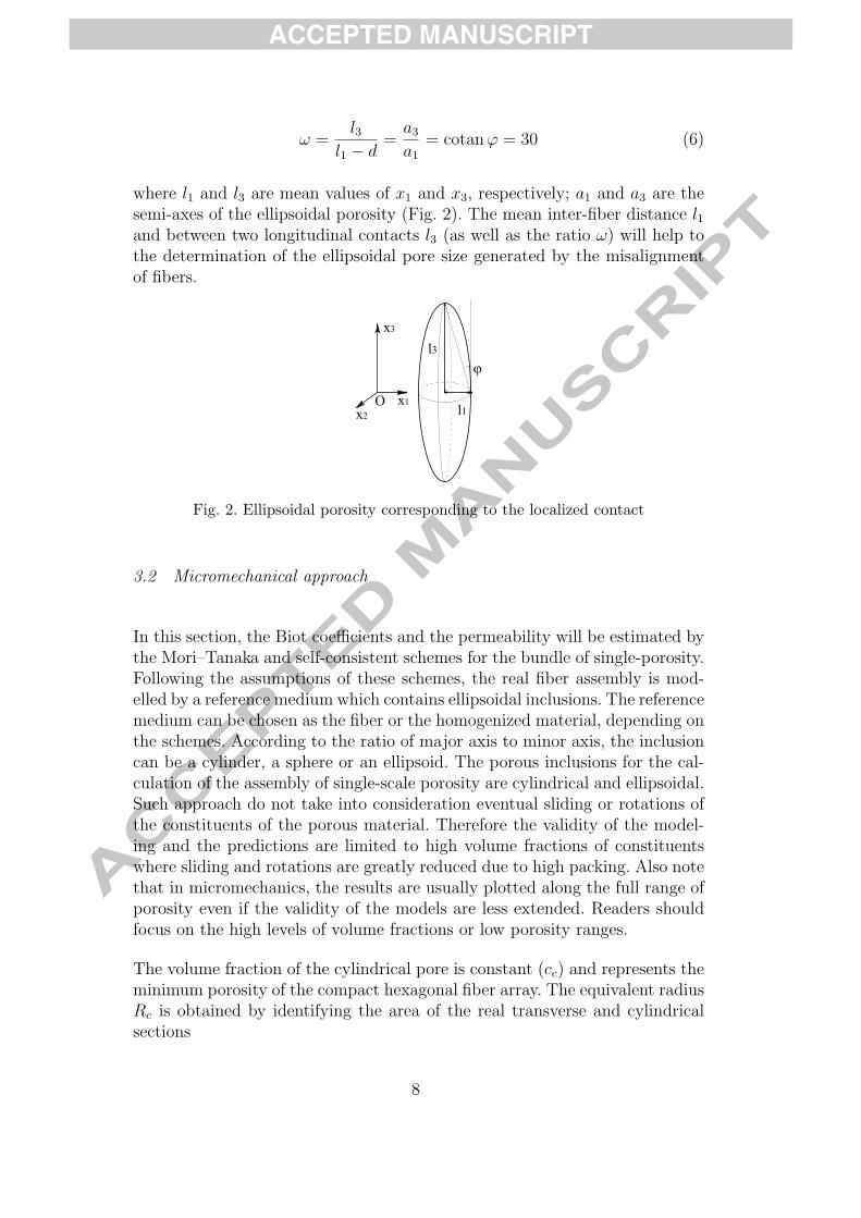
ω =l3
l1 − d=a3
a1
= cotanϕ = 30 (6)
where l1 and l3 are mean values of x1 and x3, respectively; a1 and a3 are thesemi-axes of the ellipsoidal porosity (Fig. 2). The mean inter-fiber distance l1and between two longitudinal contacts l3 (as well as the ratio ω) will help tothe determination of the ellipsoidal pore size generated by the misalignmentof fibers.
Fig. 2. Ellipsoidal porosity corresponding to the localized contact
3.2 Micromechanical approach
In this section, the Biot coefficients and the permeability will be estimated bythe Mori–Tanaka and self-consistent schemes for the bundle of single-porosity.Following the assumptions of these schemes, the real fiber assembly is mod-elled by a reference medium which contains ellipsoidal inclusions. The referencemedium can be chosen as the fiber or the homogenized material, depending onthe schemes. According to the ratio of major axis to minor axis, the inclusioncan be a cylinder, a sphere or an ellipsoid. The porous inclusions for the cal-culation of the assembly of single-scale porosity are cylindrical and ellipsoidal.Such approach do not take into consideration eventual sliding or rotations ofthe constituents of the porous material. Therefore the validity of the model-ing and the predictions are limited to high volume fractions of constituentswhere sliding and rotations are greatly reduced due to high packing. Also notethat in micromechanics, the results are usually plotted along the full range ofporosity even if the validity of the models are less extended. Readers shouldfocus on the high levels of volume fractions or low porosity ranges.
The volume fraction of the cylindrical pore is constant (cc) and represents theminimum porosity of the compact hexagonal fiber array. The equivalent radiusRc is obtained by identifying the area of the real transverse and cylindricalsections
8

ACCEPTED MANUSCRIPT
Rc = R
√2√
3− π2π
(7)
where R is the radius of an equi-diameter fiber.
The volume fraction of the ellipsoidal pore ce is the remaining porosity
ce = c− cc (8)
where c is the total porosity of the assembly.
The minor semi-axis of the ellipsoid a1 is a1 = (l1− d)/2, the major semi-axisis a3 = l3/2. The semi-axes a1 and a3 are used to compute the Biot coefficientsand permeability estimates of unidirectional assemblies of single-scale porosity.
3.2.1 Biot coefficients estimate
The Biot coefficients will be estimated by the Mori–Tanaka scheme, which hasproved more advantages compared to the dilute and Ponte Castaneda–Willisschemes for the calculation of fiber assembly [1]. The calculation assumptionsfor the unidirectional fiber assembly in localized contacts are:
• the fiber and the fiber assembly are both linear elastic;• the real fiber assembly (Fig. 3) is modelled by a reference medium, the fiber,
which contains the cylindrical and ellipsoidal pores (Fig. 4).
The ellipsoidal pore is illustrated as a “closed” pore in Fig. 4, but it implicitlycharacterizes an “opened” pore because its rigidity is null.
Fig. 3. Real unidirectional fiber assembly with misalignment
The Biot coefficients are determined by the following formulae [43]
9

ACCEPTED MANUSCRIPT
Fig. 4. Modelled unidirectional fiber assembly with misalignment
B = δ(I− Sf : Chom
MT
)(9)
where δ is the second-order unit tensor; I is the fourth-order unit tensor; Sfis the compliance tensor of the fiber and Chom is the homogeneous stiffnesstensor. The latter is calculated by the Mori–Tanaka scheme
ChomMT = (1− c)Cf :
((1− c)I +
∑i
ci(I− SEi )−1
)−1
(10)
where Cf is the stiffness tensor of the fiber; SE is the Eshelby tensor. Theindex i refers to c (cylindrical pore) or e (ellipsoidal pore).
Because of the presence of ellipsoidal pores, the Eshelby tensor cannot bedetermined analytically [44], thus the homogeneous stiffness tensor Chom
MT iscalculated numerically within the Walpole basis [45].
Figure 5 shows the Biot coefficient curves of the assembly of fibers of Kevlar 29and carbon at ratios of major to minor axes of the ellipsoidal pore ω = 30. Notethat both fibers are transversely isotropic. The curves of fibers of Kevlar 29are compared to those of perfectly straight unidirectional fiber assembly ones(ω = +∞). The Biot coefficients of perfectly straight assembly of transverselyisotropic fibers can be calculated analytically because there are only cylindricalpores.
b1 = b2 = c2c(E3 − E1ν
231)
E3[c(1 + ν12) + (1− ν12)]− 2E1ν231
(11)
b3 =E3 {(1 + ν12)[2ν31(1− c) + c] + (1− ν12)} − 2E1ν
231
E3[c(1 + ν12) + (1− ν12)]− 2E1ν231
(12)
10

ACCEPTED MANUSCRIPT
where Ei are the elastic moduli according to the direction i; νij are the Poissonratios in the plane ij. Here the direction Ox3 is oriented along the fiber axisand the (Ox1;Ox2) plane is the transverse one.
0 0.094 0.2 0.4 0.6 0.8 10
0.2
0.4
0.6
0.8
1
Porosity c
Bio
t coe
ffici
ent b
b1K
ω=30
b3K
ω=30
b1K
ω=+∞
b3K
ω=+∞
b1C
ω=30
b3C
ω=30
Fig. 5. Biot coefficients for unidirectional fiber assembly in localized (ω = 30) andin perfect (ω = +∞) contacts. The mechanical characteristics of the fiber of Kevlar29 (subscript “K”) are: E3 = 72 GPa; E1 = 5.5 GPa; µ31 = 2 GPa (axial shearmodulus); ν31 = 0.36; ν12 = 0.3 [46]; of the fiber of carbon (subscript “C”) are:E3 = 220 GPa; E1 = 14 GPa; µ31 = 9 GPa; ν31 = 0.2; ν12 = 0.25 [47]
The comparison of the Biot coefficient curves in Fig. 5 leads to the followingconclusions:
• the ellipsoidal form of pore (via ω ratio) seems to less influence the Biotcoefficients. The Biot coefficients for unidirectional fiber assembly in local-ized and in perfect contacts coincide. More precisely, b1(ω=+∞) > b1(ω=30)
and b3(ω=+∞) < b3(ω=30) for a very small value. That means, the rigidity ac-cording to the axis direction of the cylindrical pore is highest, and smallestfor the transverse directions. These rigidities reduce in the longitudinal andincrease in the transverse directions if the pore is ellipsoidal, and equal if thepore is spherical. The difference between the Biot coefficients for unidirec-tional fiber assembly in localized and in perfect contacts becomes significantwhen ω < 5;• the Biot coefficients for a perfectly straight unidirectional fiber assembly is
independent of the axial shear modulus of the fiber µ31 (Eqs. 11 and 12),but it is not the case of unidirectional fiber assembly in localized contact be-cause the presence of ellipsoidal pore causes the sliding during the isotropiccompression. However the axial shear modulus slightly influences the Biotcoefficients;• the Biot coefficient curves of unidirectional fiber assembly in localized con-
tact start at a porosity of 0.094 because it represents the minimal porosityof a unidirectional equi-diameter fiber assembly;• the Biot coefficients are lower than one because of the low Poisson ratios of
aramid fiber (same trend for carbon fiber).
11

ACCEPTED MANUSCRIPT
3.2.2 Permeability tensor estimate
The homogenization method is the calculation of macroscopic characteristicof material as function of constituent characteristics and microstructure. Forthe case of assembly of compact fiber, the macroscopic permeability cannot becalculated as function of the fiber permeability because the latter is null andtherefore does not allow any flow. For this reason, the reference medium cannotbe chosen as the fiber, thus the Mori–Tanaka scheme is no longer applicable.The only scheme that can be used in this case is the self-consistent where thereference medium is the homogenized one.
The unidirectional fiber assembly in localized contact (Fig. 3) is modelled bya homogeneous medium which contains three types of inclusions: cylindricalpore, ellipsoidal pore and cylindrical fiber (Fig. 6).
Fig. 6. Modelled material for the permeability determination by the self-consistentscheme
The homogeneous permeability tensor of the self-consistent scheme KhomSC
writes [43]
KhomSC =
⟨Ki
[I + P hom
iSC (Ki −KhomSC )
]−1⟩⟨[
I + P homiSC (Ki −Khom
SC )]−1
⟩−1
(13)
where Ki is the permeability tensor of the inclusion i; I is there second-orderunit tensor and P hom
iSC is a tensor calculated by
P homiSC = SEi (Khom
SC )−1 (14)
where SEi is the Eshelby tensor for the permeability calculation [44].
As already mentioned, the permeability of the fiber is null. The permeabilitytensor of the cylindrical pore is calculated from the Poiseuille flow solution in
12

ACCEPTED MANUSCRIPT
a tube of radius Rc
Kc =
0 0 0
0 0 0
0 0 R2c
8
(15)
The permeability tensor of the ellipsoidal pore is
Ke =
Ke1 0 0
0 Ke2 0
0 0 Ke3
(16)
where Kei is the permeability according to the direction i, they are calculatedfrom the flow solution in a tube of elliptical section (whose semi-axes are aej,aek). For example, the permeability according to the direction Ox1 is [48]
Ke1 =a2e2a
2e3
4(a2e2 + a2
e3)(17)
The flow through the ellipsoidal pore is assimilated to the flow in a tube ofellipsoidal section. The relative contribution of the permeabilities in Eq. 13 isdictated by the Eshelby tensor SEi .
Equation 13 is calculated numerically and iteratively by giving an initial guessof the homogeneous permeability tensor Kt
SC (t is the iteration counter)
Kt+1SC =
⟨Ki
[I + P t
SC(Ki −KtSC)
]−1⟩⟨[
I + P tSC(Ki −Kt
SC)]−1
⟩−1
(18)
The iterative resolution (Eq. 18) is stopped when
∣∣∣∣∣Kt+1pq,SC −Kt
pq,SC
Ktpq,SC
∣∣∣∣∣ < εer (19)
where the subscript pq are the components of the permeability tensor; εer isthe maximum allowed relative error.
13

ACCEPTED MANUSCRIPT
The calculation of the permeability tensor KhomSC is stopped when εer = 10−6.
The predictions of KhomSC (m2) are presented in Fig. 7 as a function of the
bundle porosity c. They are compared to the Gebart’s model (Eqs. 20 and21) [49], which are used for the unidirectional fiber assembly in non compacthexagonal array
KG1 = KG2 =16
9π√
2
√1− cc1− c
− 1
5/2
R2 (20)
KG3 =8
57
c3
(1− c)2R2 (21)
0 0.2 0.4 0.6 0.8 110
−20
10−15
10−10
Porosity c
Kho
mS
C (
m2 )
K1hom K
2hom − SC
K3hom − SC
K1 K
2 − Gebart
K3 − Gebart
c*
Fig. 7. The permeability of unidirectional fiber assembly calculated by the self-con-sistent (SC) scheme and Gebart formulae [49]. The diameter of the fiber is 15 µm(corresponding to glass fibers)
The permeability Khom3SC exists above cc (porosity of the cylindrical pore, which
corresponds to the porosity of the compact hexagonal fiber array) becausethere is always a minimum (non zero) porosity according to this direction.On the other hand, the permeabilities in the transverse directions of assem-bly Khom
1SC and Khom2SC are null for a porosity smaller than c∗ ≈ 0.6. Beyond
this threshold, the existence of the macroscopic permeability is interpreted asthe result of the pore connectivity, especially of ellipsoidal pores. The self-consistent scheme thus takes into account the notion of percolation threshold[50]. The connectivity of pores results from the porosity increase in the mod-eled material.
In comparison to the permeability curves of a unidirectional fiber assemblyin non compact hexagonal array predicted by the Gebart’s model [49], thepermeabilities calculated by the self-consistent scheme are lower. This wasexpected because Gebart’s model assumes perfectly aligned fibers, which is notthe case when misalignment is introduced in the bundle. Moreover, according
14

ACCEPTED MANUSCRIPT
to the Gebart’s model, the longitudinal permeability is always higher thanthe transverse ones, while for the self-consistent scheme, this is only true fora porosity lower than c ≈ 0.7.
The calculation by the self-consistent scheme allows to establish the follow-ing conclusions for the permeability tensor calculation of unidirectional fiberassembly of single-scale porosity by micromechanical approach:
• the self-consistent scheme can be used for the permeability tensor calculationof unidirectional fiber assembly of single-scale porosity. This is due to arepresentation of the reference medium which is homogeneous (because anycomponent of material can be chosen as the reference medium);• the application of the self-consistent scheme is very limited because the per-
meability is null for a porosity smaller than a critical one c∗ (the thresholdof pore connectivity). The threshold depends on the shape of the consideredpore. For the assumption of the cylindrical and ellipsoidal pores correspond-ing to the considered case, c∗ is high (≈ 0.6), thus the existing interval ofthe permeability tensor is not interesting because it corresponds to the com-posites processing at the end of the consolidation;• the self-consistent scheme equation is solved iteratively and numerically
(except for some particular cases of inclusions);• for high porosity, the model can be questionable since the flow is not dom-
inated anymore by flow in channels (Eq. 17).
Thus, these remarks suggest that the micromechanical approach does not welladapt to the permeability tensor calculation of the unidirectional fiber assem-bly of single-scale porosity. Therefore for the the single-scale porosity medium,models based on the lubrication approaches are used instead of the microme-chanical ones in the following.
4 Microporomechanical approach for unidirectional reinforcementof double-scale porosity
In reality, most of fiber reinforcements contain double-scale porosities (e.g.multiaxial non-crimp fabric, woven fabric. . . ) For these reinforcements, micro-pores and macropores exist. The micropores are located in the bundle (intra-bundle pores) which have already been studied in section 3. The macroporesare surrounding the bundles (inter-bundle or inter-layer pores) and are causedby the bundles arrangement within a ply and by ply lay-up.
This section studies the compression modulus and the permeability of the uni-directional non-crimp fabric. It consists of unidirectional fiber bundles, whichare assembled by small transverse and longitudinal threads. The bundle itself
15

ACCEPTED MANUSCRIPT
consists of unidirectional fibers in localized contact.
4.1 Transverse compression modulus
The compression modulus is calculated for a non-crimp unidirectional rein-forcement made of high strength carbon fiber (Fig. 8). For this reinforcement,there are two types of pores: micropore (intra-bundle) and macropore (inter-bundle and inter-layer). Very fine longitudinal and transverse threads holdthe bundle (Fig. 9). The thickness of these threads (according to the directionOx2) is very small. Moreover, the compression modulus is calculated only at ahigh compressive force leading to a small porosity in the reinforcement, whichis a condition of validity for the estimated schemes. That is why the inter-layermacropore a© is neglected and only the inter-bundle (ellipsoidal) pore b© isconsidered. The properties of the inter-bundle pore are given in Tab. 1. Theseproperties are obtained by image analysis where a1, a2 and a3 are the threesemi-axes of the modelled ellipsoidal pore according to the corresponding di-rections. During the compression, the thickness of reinforcement reduces, butit is assumed that the distances between the bundles and between the trans-verse threads remain unchanged. Therefore, values of a1 and a3 are supposedconstant.
X3
X2
OX1
Fig. 8. Non-crimp unidirectional fabric
Fig. 9. Bundle with very fine longitudinal and transverse threads
Since the non-crimp UD reinforcement is a double-scale porosity medium, adouble homogenization is required to assess macroscopic properties. The firsthomogenization is calculated similarly to that of the compression modulus of
16

ACCEPTED MANUSCRIPT
Table 1Ellipsoidal macropore properties
Ellipsoidal macropore
Volume fraction 0.12
Semi-axis a1 (mm) 0.5
Semi-axis a2 (mm) h/2 (Eq. 23)
Semi-axis a3 (mm) 6
the bundle as function of the fiber properties and the bundle microstructure(fiber volume fraction caused by the fiber misalignment). This homogenizationstep has already been carried out in section 3.2.1. The second homogeniza-tion consists in the calculation of the compression modulus of the non-crimpUD reinforcement as function of the bundle modulus and the reinforcementmicrostructure (caused by the bundle arrangement). The real reinforcementis modelled by a reference medium (the bundle) which contains ellipsoidalmacropores. The Mori–Tanaka formula is used for the double-scale porosity(Eq. 10).
Owing to the presence of ellipsoidal macropore of three different semi-axes,the non-crimp UD fabric is no longer transversely isotropic but orthotropic,thus the homogeneous stiffness tensor is composed of 9 independent com-ponents. The micromechanical calculation is carried out within the Walpolebasis for orthotropic material [45]. For example, the compliance tensor S ofthe orthotropic material writes in the Walpole basis
S =
1
E1
−ν21
E2
−ν31
E3
−ν21
E2
1
E2
−ν32
E3
−ν31
E3
−ν32
E3
1
E3
,
1
2µ12
,1
2µ23
,1
2µ13
(22)
The compression modulus E2 according to the direction Ox2 is estimatednumerically in the fiber content interval [0.65 ; 0.75] because this is an in-teresting interval of porosity of the material during composite manufacturingand it complies with the values given in Tab. 1 and the assumption that thepore a© (Fig. 9) does not exist. The thickness of the layer (axis a2) is deducedfrom the fiber volume fraction Vf
h =ρsVfρv
(23)
17

ACCEPTED MANUSCRIPT
where ρs is the areal weight of the non-crimp UD reinforcement and ρv is thedensity of the fiber. This extrapolation is valid only for a small interval of Vf .
The estimated modulus Ehom2MT of the non-crimp UD reinforcement is presented
in Fig. 10. The compression modulus is smaller than the one of the bundlebecause of the presence of macropores. Compression modulus can be foundin the literature or experimentally. For this study, uniaxial compression testshave been performed on dry carbon NCF and the tangent compression mod-ulus was around 0.9GPa at the fiber volume fraction of 65%. The differencebetween that experimental value and the estimated values are due to themicromechanical assumptions (no sliding and no rotations) which stiffen themodeled material. Also, concerns remain regarding the way to measure andcalculte the compression modulus from an experimental curve.
0 0,2 0,4 0,6 0.7 0,80.906 10
5
10
15
Fiber volume fraction Vf
Com
pres
sion
mod
ulus
(G
Pa)
E1MThom E
2MThom bundle
E1MThom HR
Fig. 10. Calculated compression modulus of the non-crimp UD reinforcement of(high strength) carbon fiber. The transverse Young’s modulus of (high strength)carbon fiber is 15 GPa
4.2 Permeability estimate
As seen previously (section 3.2.2), the estimation schemes are not well adaptedto the permeability calculation of the unidirectional assemblies of single-scaleporosity because of the difficulty to choose a reference medium that allows toperform calculations. But for the reinforcement of double-scale porosity, thereference medium can be chosen as the bundle of single-scale porosity, whosepermeability is calculated by the Gebart’s model [49].
The permeabilities will be estimated by the Mori–Tanaka scheme for anothernon-crimp UD reinforcement made of glass fibers (Fig. 11). It is also a rein-forcement containing double-scale porosity, identically to the previous fabricstudied, i.e. there are intra-bundle micropores and inter-bundle and inter-layer
18

ACCEPTED MANUSCRIPT
macropores (Fig. 12). The longitudinal and transverse threads somehow hin-der the resin flow, thus the pores are assumed ellipsoidal and not cylindrical.
Fig. 11. Glass non-crimp unidirectional reinforcement
5 mm
macroporosityzone
microporosityzone
X2
X3
OX1
Fig. 12. Transverse micrography of the stacking of 6 layers of glass non-crimp uni-directional reinforcement
The Mori–Tanaka scheme is applied by considering that there are two ellip-soidal macropore families: ellipsoidal inter-bundle macropore and penny-shapeinter-layer macropore, which are present in a reference medium, the bundle(Fig. 13).
Fig. 13. Modelled glass UD NCF for the Mori–Tanaka scheme
The properties of the ellipsoidal macropore are determined from micrographiesand presented in Tab. 2. Some values of ellipsoidal macropores are extrapo-lated by modifying the semi-axis a2 by Eq. 23 for more values of the estimated
19

ACCEPTED MANUSCRIPT
permeability curves. The other semi-axes are unchanged for the different thick-nesses of the glass non-crimp reinforcement.
Table 2Properties of the macropores
Ellipsoidal macropore Penny-shape macropore
Volume fraction 0.140 0.031
Semi-axis a1 (mm) 0.175 1.077
Semi-axis a2 (mm) 0.379 0.013
Semi-axis a3 (mm) 1.650 1.650
The homogeneous permeability tensor KhomMT of the glass non-crimp reinforce-
ment is calculated for the material of n pore families [43]
KhomMT = KB +
[n∑i=1
fi(Ki −KB)Di
] [I +
n∑i=1
fi(Di − I)
]−1
(24)
where:
Di = [I + P i(Ki −KB)]−1 (25)
where KB is the permeability tensor of the bundle (the reference medium)whose diagonal components are determined by the Gebart’s model (Eqs. 20and 21), Ki are the macropore permeabilities, they are calculated as the flowin a tube of elliptical section (the section of the penny-shape and ellipsoidalmacropore, Eq. 17), fi is the volume fraction of the i pore family and Pi is de-fined as in Eq. 14. Connectivity is provided by the reference media (permeablebundle) and the presence of macro ellipsoidal pores.
The permeability curves estimated by the Mori–Tanaka scheme for the uni-directional glass non-crimp reinforcement are presented in Fig. 14. The per-meability according to the longitudinal direction is compared to experimentalvalues, which have been measured by compression and injection methods [23].The estimated and experimental results are in good agreement. The perme-abilities are lower than the experimental ones. This is probably due to the factthat only ellipsoidal pores have been used in the calculations. Such choice hasbeen made because a small weaving thread in present along the main bundlesand hinders the flow. In reality there must be a stronger pore connectivitythat should be represented by cylindrical pores which would give a higher es-timated permeability. Since the determination of the size and the amount ofsuch cylindrical pore was not possible from micrographs, it has been decidedto only consider ellipsoidal pores. Such results emphasize the interest in such
20

ACCEPTED MANUSCRIPT
48 50 52 54 56 58 60 62
10−12
10−11
10−10
Fiber volume fraction Vf
K (
m2 )
K1MThom
K2MThom
K3MThom
K3 Compression
K3 Injection
Fig. 14. Estimated permeabilities by the Mori–Tanaka scheme compared to theexperimental values for the glass UD NCF
unified method allowing to get hydromechanical, flow and mechanical prop-erties of fiber reinforcement and also because the permeability is difficult todetermine experimentally.
5 Conclusion
The microporomechanical theory has been applied to unidirectional reinforce-ments to calculate Biot coefficients, compression modulus and permeability.This is a development based on the previous study of perfectly straight unidi-rectional fiber assembly [1], while the fiber in the present work is transverselyisotropic, in localized contact and the fibrous material consists of double-scaleporosity. This development widens the solution to transversely isotropic fibers(carbon or aramid). Furthermore, the calculation is carried out for the double-scale porosity, orthotropic reinforcement, which is closer to industrial materialsin the composites processing.
The present results prove that the Biot coefficients of bundles made of trans-versely isotropic fibers like carbon or aramid are always lower than one, and forthe same porosity, the Biot coefficients of the perfectly straight unidirectionalfiber assembly are not much different to that in localized contact.
The micromechanical approach stiffens the fibrous material because it hin-ders the possible sliding and rotations that can occur in such non-cohesivematerials. The result validity is therefore limited to high fiber volume frac-tions. However, using consecutive homogenizations allow to obtain mechanicalproperties at lower fiber volume fractions.
The permeability tensor is also calculated by the microporomechanical ap-
21

ACCEPTED MANUSCRIPT
proach, but it is not well adapted to the misaligned unidirectional fiber as-sembly of single-scale porosity because of the difficulty to choose a referencemedium. The permeability of an array of solid fiber should be determined withregular fluid mechanics methods. However, permeabilities of the reinforcementof double-scale porosity can be predicted by this continuum approach, andthey have showed good agreement with experimental results.
The obtained results prove that the microporomechanical approach could beapplied to the fiber reinforcement in the processing of composites and offersan unified consistent framework to model fluid-related and fiber-related phe-nomena involved in the composites manufacturing processes.
References
[1] Tran T, Binetruy C, Comas-Cardona S, Abriak NE. Microporomechanicalbehaviour of perfectly straight unidirectional fiber material: theoretical andexperimental. Compos Sci Technol 2009;69:199-206.
[2] Mazumdar SK. Composites manufacturing: materials, product and processengineering. CRC Press, 2001.
[3] Binetruy C, Krawczak P. Compression des renforts dans les procedes LCM. 2:Modelisation de la permeabilite. Rev Compos Mater Av 2002;12:265-84.
[4] Gauvin R, Chibani M. The modeling of mold filling in resin transfer molding.Int Polym Proc 1986;1:42-46.
[5] Kardos JL, Lam RC. The permeability and compressibility of aligned andcross-plied carbon fiber beds during processing of composites. Polym Eng Sci1991;31:1064-70.
[6] Kenny JM, Molina G, Trivisano A. Mathematical modelling of resin transfermolding of composites for automotive applications. In: ICCM proceedings,Madrid, Spain, July 12-16th, 1993; p. 513-20.
[7] Bruno A, Mazzola M, Molina G. Modelisation de l’ecoulement et validationexperimentale du procede RTM. Composites 1992;3:397-404.
[8] Adams KL, Miller B, Rebenfeld L. Forced in-plane flow of an epoxy resin infibrous networks. Polym Eng Sci 1986;26:1434-41.
[9] Advani SG, Bruschke MV. A finite element/control volume approach to moldfilling in anisotropic porous media. Polym Compos 1990;11:398-405.
[10] Lee LJ, Perry MJ, Wang TJ. Analysis of permeability and void formation inresin transfer molding. In: ANTEC proceedings, Detroit, USA, May 3-7th, 1992;p. 756-60.
22

ACCEPTED MANUSCRIPT
[11] Endruweit A, Luthy T, Ermanni P. Investigation of the influence of textilecompression on the out of plane permeability of a bidirectional glass fiber fabric.Polym Compos 2002;23:538-54.
[12] Bauer S, Boucher D, Gutowski TG. Consolidation experiments for laminatecomposites. J Compos Mater 1987;21:650-69.
[13] Han KK, Lee CW, Rice BP. Measurements of the permeability of fibre preformsand applications. Compos Sci Technol 2000;60:2435-41.
[14] Ahn SH, Lee WI, Springer GS. Measurement of the three-dimensionalpermeability of fiber preforms using embedded fiber optic sensors. J ComposMater 1995;29:714-33.
[15] Weitzenbock JR, Shenoi RA, Wilson PA. Measurements of three-dimensionalpermeability. Composites Part A 1998;29:159-69.
[16] Woerdeman DL, Phelan FR, Parnas RS. Interpretation of 3D permeabilitymeasurements for RTM modelling. Polym Compos 1995;16:470-80.
[17] Lundstrom TS, Stenberg R, Bergstrom R, Partanen H, Birkeland PA. In-planepermeability measurements: a nordic round-robin study. Composites Part A2000;31:29-43.
[18] Parnas RS, Flynn KM, Dal-Favero ME. A permeability database for compositesmanufacturing. Polym Compos 1997;18:623-33.
[19] Feser JP, Prasad AK, Advani SG. Experimental characterization of in-planepermeability of gas diffusion layers. J Power Sources 2006;162:1226-31.
[20] Pomeroy R, Grove S, Summerscales J, Wang Y, Harper A. Measurement ofpermeability of continuous filament mat glass-fibre reinforcements by saturatedradial airflow. Composites Part A 2007;38:1439-43.
[21] Ait Si Ahmad M, Fasi-Ferhi O, Poitou A, Bojji C. Model for determining thepermeability variation of fiber mat reinforcement submitted to compression.Mec Ind 2002;3:27-34.
[22] Buntain MJ, Bickerton S. Compression flow permeability measurement: acontinuous technique. Composites Part A 2003;34:445-57.
[23] Comas-Cardona S, Binetruy C, Krawczak P. Unidirectional compression of fibrereinforcements. Part 2: A continuous permeability tensor measurement. ComposSci Technol 2007;67:638-45.
[24] Lundstrom TS. The permeability of non-crimp stitched fabrics. CompositesPart A 2000;31:1345-53.
[25] Simacek P, Karbhari VM. Notes on the modeling of preform compaction. I:Micromechanics at the fiber bundle level. J Reinf Plast Compos 1996;15:86-122.
23

ACCEPTED MANUSCRIPT
[26] Song YS, Chung K, Kang TJ, Youn JR. Prediction of permeability tensor forthree dimensional circular braided preform by applying a finite volume methodto a unit cell. Compos Sci Technol 2004;64:1629-36.
[27] Fournier R, Coupez T, Vincent M. Numerical determination of the permeabilityof fibre reinforcement for the RTM process. Revue Europeenne des ElementsFinis 2005;14:803-18.
[28] Belov EB, Lomov SV, Verpoest I, Peters T, Roose D, Parnas RS, Hoes K, Sol H.Modelling of permeability of textile reinforcements: lattice Boltzmann method.Compos Sci Technol 2004;64:1069-80.
[29] Comas-Cardona S, Groenenboom PHL, Binetruy C, Krawczak P. Simulationof liquid molding processes using a generic mixed FE-SPH method. RevueEuropeenne des Elements Finis 2005;14:867-83.
[30] Nedanov PB, Advani SG. Numerical computation of the fiber preformpermeability tensor by the homogenization method. Polym Compos2002;23:758-70.
[31] Chen B, Cheng AHD, Chou TW. A nonlinear compaction model for fibrouspreforms. Composites Part A 2001;32:701-07.
[32] Toll S, Manson JAE. An analysis of the compressibility of fiber assemblies.6th International Conference on Fiber Reinforced Composites, Institute ofMaterials. Newcastle-upon-Tyne, UK, 1994; p. 25/1-25/10.
[33] Lekakou C, Johari MAKB, Bader MG. Compressibility and flow permeability oftow-dimensional woven reinforcements in the processing of composites. PolymCompos 1996;17:666-72.
[34] Melro AR, Camanho PP, Pinho ST. Generation of random distribution of fibresin long-fibre reinforced composites. Compos Sci Technol 2008;68:2092-102.
[35] Pyrz R. Quantitative description of the microstructure of composites. PartI: Morphology of unidirectional composite systems. Compos Sci Technol1994;50:197-208.
[36] Pyrz R. The application of morphological methods to composite materials.Comprehensive Composite Materials 2003;2:553-76.
[37] Chiu SN. Aboav-Weaire’s and Lewis’s laws: a review. Mater Charact1995;34:149-65.
[38] Soille P. On the validity of fractal dimension measurements in image analysis.J Vis Commun Image R 1996;7:217-29.
[39] Gusev AA, Hine PJ, Ward IM. Fiber packing and elastic properties of atransversely random unidirectional glass/epoxy composite. Compos Sci Technol2000;60:535-41.
[40] Torquato S, Lu B. Chord-length distribution for 2-phase random-media. PhysicsReview E 1993;47:2950-53.
24

ACCEPTED MANUSCRIPT
[41] Yurgartis SW. Measurement of small angle fiber misalignments in continuousfiber composites. Compos Sci Technol 1987;30:279-93.
[42] Lee J, Soutis C. Thickness effect on the compressive strength of T800/924Ccarbon fiber-epoxy laminates. Composites Part A 2005;36:213-27.
[43] Dormieux L, Kondo D, Ulm FJ. Microporomechanics. John Wiley & Sons Inc.;2006.
[44] Eshelby JD. The determination of the elastic field of an ellipsoidal inclusion,and related problems. Proc Roy Soc Lond A 1957;241:376-96.
[45] Walpole LJ. Fourth-rank tensors of the thirty-two crystal classes: multiplicationtables. Proc R Soc Lond A 1984;391:149-79.
[46] Camacho CW, Tucker CL, Yalvac S, Mcgee RL. Stiffness and thermal expansionpredictions for hybrid short fiber composites. Polym Composite 1990;11:229-39.
[47] Chamis CC. Simplified composite micromechanics for predicting microstresses.J Reinf Plast Compos 1987;6:268-89.
[48] Comolet R. Mecanique experimentale des fluides. Tome 2: Dynamique desfluides reels, turbomachines. Masson; 1994.
[49] Gebart BR. Permeability of unidirectional reinforcements for RTM. J ComposMater 1992;26:1100-33.
[50] Dormieux L, Kondo D. Approche micromecanique du couplage permeabilite-endommagement. Compte Rendu Mecanique 2004;332:135-40.
25