Dynamic analysis of unidirectional pressure infiltration of porous preforms by pure metals
10
Cleveland State University EngagedScholarship@CSU Chemical & Biomedical Engineering Faculty Publications Chemical & Biomedical Engineering Department 1-1-1998 Dynamic Analysis of Unidirectional Pressure Infiltration of Porous Preforms by Pure Metals Dhiman K. Biswas Comsys Jorge E. Gatica Cleveland State University, [email protected] Surendra N. Tewari Cleveland State University, [email protected] Follow this and additional works at: hp://engagedscholarship.csuohio.edu/encbe_facpub Part of the Materials Science and Engineering Commons , and the Transport Phenomena Commons Publisher's Statement Copyright 1998 ASM International. is paper was published in Metallurgical and Materials Transactions A: Physical Metallurgy and Materials Science, Vol. 29, Issue 1, pp. 377-385 and is made available as an electronic reprint with the permission of ASM International. One print or electronic copy may be made for personal use only. Systematic or multiple reproduction, distribution to multiple locations via electronic or other means, duplications of any material in this paper for a fee or for commercial purposes, or modification of the content of this paper are prohibited. Available on publisher's site at: hp://www.asminternational.org/portal/site/www/AsmStore/ProductDetails/ ?vgnextoid=0d921774ef326210VgnVCM100000621e010aRCRD. Repository Citation Biswas, Dhiman K.; Gatica, Jorge E.; and Tewari, Surendra N., "Dynamic Analysis of Unidirectional Pressure Infiltration of Porous Preforms by Pure Metals" (1998). Chemical & Biomedical Engineering Faculty Publications. Paper 11. hp://engagedscholarship.csuohio.edu/encbe_facpub/11 is Article is brought to you for free and open access by the Chemical & Biomedical Engineering Department at EngagedScholarship@CSU. It has been accepted for inclusion in Chemical & Biomedical Engineering Faculty Publications by an authorized administrator of EngagedScholarship@CSU. For more information, please contact [email protected]. Original Citation Biswas, D.K., Gatica, J.E., & Tewari, S.N. (1998). Dynamic Analysis of Unidirectional Pressure Infiltration of Porous Preforms by Pure Metals. Metallurgical and Materials Transactions A: Physical Metallurgy and Materials Science 29, 377-385.
Transcript of Dynamic analysis of unidirectional pressure infiltration of porous preforms by pure metals

Cleveland State UniversityEngagedScholarship@CSUChemical & Biomedical Engineering FacultyPublications Chemical & Biomedical Engineering Department
1-1-1998
Dynamic Analysis of Unidirectional PressureInfiltration of Porous Preforms by Pure MetalsDhiman K. BiswasComsys
Jorge E. GaticaCleveland State University, [email protected]
Surendra N. TewariCleveland State University, [email protected]
Follow this and additional works at: http://engagedscholarship.csuohio.edu/encbe_facpubPart of the Materials Science and Engineering Commons, and the Transport Phenomena
CommonsPublisher's StatementCopyright 1998 ASM International. This paper was published in Metallurgical and Materials Transactions A: PhysicalMetallurgy and Materials Science, Vol. 29, Issue 1, pp. 377-385 and is made available as an electronic reprint with thepermission of ASM International. One print or electronic copy may be made for personal use only. Systematic ormultiple reproduction, distribution to multiple locations via electronic or other means, duplications of any material inthis paper for a fee or for commercial purposes, or modification of the content of this paper are prohibited.Available on publisher's site at: http://www.asminternational.org/portal/site/www/AsmStore/ProductDetails/?vgnextoid=0d921774ef326210VgnVCM100000621e010aRCRD.
Repository CitationBiswas, Dhiman K.; Gatica, Jorge E.; and Tewari, Surendra N., "Dynamic Analysis of Unidirectional Pressure Infiltration of Porous Preforms by PureMetals" (1998). Chemical & Biomedical Engineering Faculty Publications. Paper 11.http://engagedscholarship.csuohio.edu/encbe_facpub/11
This Article is brought to you for free and open access by the Chemical & Biomedical Engineering Department at EngagedScholarship@CSU. It hasbeen accepted for inclusion in Chemical & Biomedical Engineering Faculty Publications by an authorized administrator of [email protected] more information, please contact [email protected].
Original CitationBiswas, D.K., Gatica, J.E., & Tewari, S.N. (1998). Dynamic Analysis of Unidirectional Pressure Infiltration of Porous Preforms by PureMetals. Metallurgical and Materials Transactions A: Physical Metallurgy and Materials Science 29, 377-385.
METALLURGICAL AND MATERIALS TRANSACTIONS A VOLUME 29A, JANUARY 1998—377
Dynamic Analysis of Unidirectional Pressure Infiltrationof Porous Preforms by Pure Metals
DHIMAN K. BISWAS, JORGE E. GATICA, and SURENDRA N. TEWARI
Unidirectional pressure infiltration of porous preforms by molten metals is investigated numer-ically. A phenomenological model to describe fluid flow and transport phenomena during infil-tration of fibrous preforms by a metal is formulated. The model describes the dynamics of theinfiltration process, the temperature distribution, and solid fraction distribution. The numericalresults are compared against classical asymptotic analyses and experimental results. This com-parison shows that end effects may become important and render asymptotic results unreliablefor realistic samples. Fiber volume fraction and initial temperature appear as the factors moststrongly influencing infiltration. Metal superheating affects not only the length of the two-phasezone but also the solid fraction distribution in the two-phase zone. The effect of constant appliedpressure, although significant on the infiltration velocity, is almost negligible on the two-phasezone length and on solid fraction distribution. When the initial preform temperature is below themetal melting point, and constant pressure is applied under adiabatic conditions, the flow ceaseswhen sufficient solidification occurs to obstruct it. A comparison with literature experimentsproves the model to be an efficient predictive tool in the analysis of infiltration processes fordifferent preform/melt systems.
I. INTRODUCTION
OVER the past 2 decades, advanced composite materi-als have progressed from a laboratory curiosity to a pro-duction reality. In principle, composites can be constructedof any combination of two or more materials. Metallic com-posites or metal-matrix composites (MMCs) reinforcedwith fibers are currently of significant interest. They offerthe opportunity to tailor a material with a combination ofproperties unavailable in any single material, e.g., combin-ing the very high tensile strength and modulus of elasticityof various types of fibers with the low density of a metalsuch as aluminum, titanium, or magnesium to obtain a com-posite material with a higher strength-to-density or modu-lus-to-density ratio than any single known alloy.
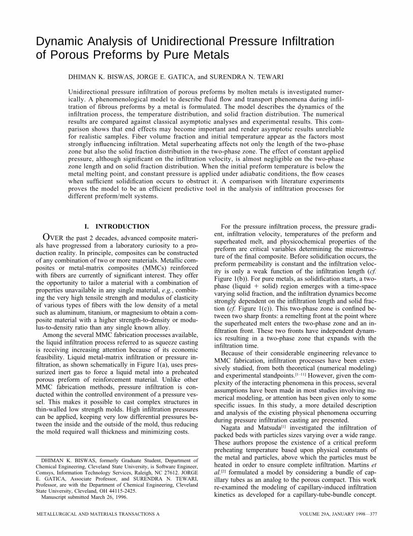
Among the several MMC fabrication processes available,the liquid infiltration process referred to as squeeze castingis receiving increasing attention because of its economicfeasibility. Liquid metal-matrix infiltration or pressure in-filtration, as shown schematically in Figure 1(a), uses pres-surized inert gas to force a liquid metal into a preheatedporous preform of reinforcement material. Unlike otherMMC fabrication methods, pressure infiltration is con-ducted within the controlled environment of a pressure ves-sel. This makes it possible to cast complex structures inthin-walled low strength molds. High infiltration pressurescan be applied, keeping very low differential pressures be-tween the inside and the outside of the mold, thus reducingthe mold required wall thickness and minimizing costs.
DHIMAN K. BISWAS, formerly Graduate Student, Department ofChemical Engineering, Cleveland State University, is Software Engineer,Comsys, Information Technology Services, Raleigh, NC 27612. JORGEE. GATICA, Associate Professor, and SURENDRA N. TEWARI,Professor, are with the Department of Chemical Engineering, ClevelandState University, Cleveland, OH 44115-2425.
Manuscript submitted March 26, 1996.
For the pressure infiltration process, the pressure gradi-ent, infiltration velocity, temperatures of the preform andsuperheated melt, and physicochemical properties of thepreform are critical variables determining the microstruc-ture of the final composite. Before solidification occurs, thepreform permeability is constant and the infiltration veloc-ity is only a weak function of the infiltration length (cf.Figure 1(b)). For pure metals, as solidification starts, a two-phase (liquid 1 solid) region emerges with a time-spacevarying solid fraction, and the infiltration dynamics becomestrongly dependent on the infiltration length and solid frac-tion (cf. Figure 1(c)). This two-phase zone is confined be-tween two sharp fronts: a remelting front at the point wherethe superheated melt enters the two-phase zone and an in-filtration front. These two fronts have independent dynam-ics resulting in a two-phase zone that expands with theinfiltration time.
Because of their considerable engineering relevance toMMC fabrication, infiltration processes have been exten-sively studied, from both theoretical (numerical modeling)and experimental standpoints.[1–11] However, given the com-plexity of the interacting phenomena in this process, severalassumptions have been made in most studies involving nu-merical modeling, or attention has been given only to somespecific issues. In this study, a more detailed descriptionand analysis of the existing physical phenomena occurringduring pressure infiltration casting are presented.
Nagata and Matsuda[1] investigated the infiltration ofpacked beds with particles sizes varying over a wide range.These authors propose the existence of a critical preformpreheating temperature based upon physical constants ofthe metal and particles, above which the particles must beheated in order to ensure complete infiltration. Martins etal.[2] formulated a model by considering a bundle of cap-illary tubes as an analog to the porous compact. This workre-examined the modeling of capillary-induced infiltrationkinetics as developed for a capillary-tube-bundle concept.
378—VOLUME 29A, JANUARY 1998 METALLURGICAL AND MATERIALS TRANSACTIONS A
(a)
(b) (c)
Fig. 1—(a) Schematic of the pressure infiltration process (b) without and (c) with partial solidification.
Girot et al.[3] presented a numerical analysis of the infiltra-tion of liquid alloys into fibrous preforms. These authorsproposed that flow would cease when the metal cools to itsliquidus temperature and, therefore, did not account for therelease of latent heat of solidification by the metal in theircalculations. Mortensen et al.[4] derived general expressionsto describe fluid flow and heat transfer during infiltrationof fibrous preforms by a pure metal. Under the conditionsof unidirectional infiltration and constant pressure differ-ence, the governing equations were significantly simplifiedand a solution by a similarity transformation was possible.The same authors also presented experimental results[5] forpure aluminum flowing into fibrous alumina preforms tocompare with their theory. Mortensen and co-workers alsoinvestigated the critical pressure necessary for melt infiltra-tion and the effect of infiltration pressure on the fiber pre-form deformation. Mortensen and Michaud[6] extended theanalysis for a binary hypoeutectic alloy. Solidification andmass transport considerations were added. In this model,however, a constant pattern of propagation with flat infil-tration and remelting fronts was assumed. Later, Calhounand Mortensen[7] analyzed the morphological stability of theremelting front of a simplified infiltration system (steady-state, unidirectional, adiabatic infiltration with a pure metal)using linear stability analysis. Lacoste et al.[8] presented a
model for the infiltration of aluminum into a SAFFIL* pre-
*SAFFIL is a nominally 3-mm-diameter d-Al2O3 fiber that is choppedand pressed into disk-shaped preforms. SAFFIL is a trademark of ICIAmericas, Inc., Wilmington, DE.
form. A one-dimensional (1-D) model was compared withexisting analytical solutions. A two-dimensional (2-D)model was formulated and solved as well. The solutions,however, show that 2-D patterns would be restricted to thevicinity of the solidification front for the operating condi-tions analyzed.
A comprehensive modeling in one and two dimensionswas reported recently by Shin[9] for the infiltration of puremetals and alloys. This author formulated a detailed modelof the process; the commercial computational fluid dynam-ics package PHOENICS[12] was used for the numerical cal-culations. A very comprehensive analysis was carried outfor a typical case study. Comparison with asymptotic ana-lytical results[5] revealed minor differences, which the au-thor attributed to the numerical treatment of the sourceterms. Despite the complexity, the model did not accountfor remelting phenomena occurring upstream from the in-filtration front when superheated melt enters in contact withpartially solidified metal. The analysis thus did not inves-tigate the effect of metal superheating on the process. The
METALLURGICAL AND MATERIALS TRANSACTIONS A VOLUME 29A, JANUARY 1998—379
study was extended to the infiltration of alloys in one andtwo dimensions. The results successfully identified some ofthe phenomena responsible for macrosegregation in com-posites prepared by alloy infiltration.
Only in very recent works have the dynamics of the in-filtration process been addressed. However, emphasis hasbeen given to more specific issues related to the propertiesof the resulting composite rather than to the infiltration pro-cess itself. Thus, for instance, Long et al.[10] analyzed theformation of noninfiltration defects during liquid metal in-filtration of unidirectional continuous fiber arrays. Theseauthors focused on the description of the microscale hydro-dynamic phenomena to predict the formation of macro andmicro noninfiltration defects in composites. Yamauchi andNishida,[11] on the other hand, concentrated their efforts onvery high-pressure (10 to 100 MPa) infiltration experi-ments, focusing their attention on preform deformation phe-nomena due to the large pressure gradients.
II. MODEL EQUATIONS AND ASSUMPTIONS
The analysis of fluid flow and transport phenomena inmanufacturing processes is usually based on the transportequations resulting from differential balance laws. The so-lution to these equations, subject to the pertinent boundaryand initial conditions, yields detailed temperature and phasedistributions. A detailed knowledge of these fields, togetherwith information about the velocity fields, allows the pre-diction of global trends and/or effects. When complexstructures such as porous media or randomly packed bedsare involved, these equations are valid even inside thepores. The geometric complexity of a randomly intercon-nected porous network prevents any general solution of de-tailed temperature, solid fraction, and flow fields. Someform of macroscopic balance based on the average over asmall volumetric element must be employed.
Even with such a simplification, the description remainsof heterogeneous nature (fluid and solid phases). It has beenshown,[13] however, that a reliable representation of a het-erogeneous medium can be achieved via a homogeneousmodel, provided the transport coefficients are suitably cho-sen. This model, known as pseudohomogeneous, treats thesystem as a quasicontinuum medium by introducing theconcept of effective transport properties. The dimensionlessenergy balances for the composite (melt and fibers) andpreform (inert gas and fibers) are
]Fc 25 2= z n F 1 r = 1 Sm c u c [1]]t]Fp 25 2= z n F 1 r = 1 Sg p u p]t
where r is density, u is the dimensionless temperature, Fis the dimensionless enthalpy, and n is the velocity vector.The subscripts c, p, m, and g signify composite, preform,melt, and gas, respectively.
The flow distribution in unbounded porous media is usu-ally well represented by a linear correlation between thepressure drop and the fluid velocity. This relation is thewell-known Darcy’s law. The use of such an approximationhas been the subject of several analyses and modifications;the details can be found elsewhere.[14] For a fluid that obeys
Boussinesq’s approximations, and for low infiltration ve-locities, the momentum equation becomes
1 1 ]v g5 2=p 2 n 1 Ra u [2]Ts Pr* ]t |g|
where Pr* is the Darcy number (or Prandtl for porous me-dia), RaT is the thermal Rayleigh number, g is the gravita-tional vector, and s is the fluid to fiber heat capacity ratio.For most situations of interest,[15] the Darcy number is muchlarger than unity (Pr* .. 1) and the time dependency canbe neglected in the momentum equation. Then, the flowfield can be accurately represented by
g0 5 2=p 2 n 1 Ra uT |g| [3]0 5 = z n
In developing Eq. [3], solid and fiber phases were assumedstationary, and the difference between solid and liquidmetal densities was assumed negligible; i.e., the momentumtransfer due to phase change was neglected. The pressuredrop was assumed independent of the infiltration front ve-locity, and the applied pressure was considered high enoughfor the flow to be slug type.
A. Initial and Boundary Conditions
To solve the governing equations, Eqs. [1] and [3], oneinitial condition and four boundary conditions are neces-sary. In this model for unidirectional infiltration with a con-stant applied pressure, there is always a period at thebeginning of the infiltration process during which high flowvelocities are observed. The use of Darcy’s law requires aflow with a Reynolds number to be below a critical value.Since the flow is characterized by an initial period of veryhigh flow velocity, which is slowed down as the infiltrationtakes place, there would be a length the metal must travelbefore the Reynolds number reaches its critical value. Thislength, often negligible when compared with the total pre-form length, is a function of system physical parameters.For instance, Masur et al.[5] found this length to be approx-imately 0.3 mm for their experimental conditions. There-fore, the equations will only be applicable after a smallsection of the preform, Lc, has been infiltrated. The initialtemperature in the melt and preform zones will then be acontinuous function, which can be approximated as the an-alytical solution to the energy balance equation in the pre-form zone; i.e.,
u for x,Lo cxu (0, x) 5 [4]$ (u 2 u ) erfc 1 u for x≥Lo p ~ ! p c2=a tp c
where tc is the time needed for the melt to travel the criticaldistance, Lc, and ap is the preform thermal diffusivity. Thevariables up and uo represent the initial preform and meltdimensionless temperatures, respectively.
Two of the boundary conditions can be formulated at the‘‘infiltration front interface,’’ which separates uninfiltratedpreform from infiltrated two-phase zone. Since the infiltra-tion front is tracked via a moving grid, no flow will occurthrough this boundary. Thermal equilibrium at the infiltra-tion front interface establishes
380—VOLUME 29A, JANUARY 1998 METALLURGICAL AND MATERIALS TRANSACTIONS A
12u 5 uL Lf f
and at x5L [5]f
12k nz=u 5 k nz=u %c L p Lf f
where Lf is the axial location of the infiltration front, nstands for the unitary vector normal to the surface, and kc
and kp are the composite and preform effective thermal con-ductivities, respectively.
The remaining two boundary conditions, inlet and exitconditions, are assumed as suggested by Danckwerts[16] forflow systems; i.e.,
2 +n zn (F 2 F ) 5 n z=u at x50o c
and [6]2n z=u 5 0 at x51
where F0 and Fc stand for the superheated metal and com-posite enthalpies, respectively.
B. Permeability and Capillary Pressure
For flow perpendicular to the fiber axes, the permeabilitycan be based on the numerical calculations of Sangani andAcrivos,[17] as
2 5/2=2 2 Rf 1 2 εk 5 1 2 2 [7]=~ !9(1 2 ε) p
where Rf is the radius of the fibers and ε is the void fraction.This equation is valid for void fractions 1 2 m/4 ≤ ε ≤ 0.8.
For flow parallel to the fiber axes, the permeability canbe based on the calculations presented by Drummond andTahir,[18]
420.427 R 2 (1 2 ε)fk 5 1 2 =@ #1 2 ε p
p 2 2(1 2 ε)1 1 0.473 [8]=@ #2(1 2 ε)
for void fractions 1 2 m/4 ≤ ε ≤ 0.5.For infiltration conditions without solidification, the void
fraction remains constant and so does the preform perme-ability. As partial solidification takes place, a void fractiondistribution will develop throughout the two-phase zone.Therefore, for solidification conditions, the preform per-meability will be a function of space and time, and theinfiltration velocity will need to be recalculated. The infil-tration velocity can be easily recalculated using the follow-ing approach:[19]
,k. DPV 5 2
m Lm f
where [9]
,k. Lf5 Lfmm µ/mmm * dxm k0
Pressure is the only driving force for infiltration to occur.This driving force can be applied externally or by capillarypressure. For wetting systems where capillary pressure isnegative, external pressure is not required to initiate infil-
tration. Liquid metals usually do not wet the fibers; there-fore, impregnation requires external pressure. Because ofthe poor wettability and small diameter of modern fibers,the pressure must be large enough to ensure an optimumcontact between matrix and fiber. However, very high pres-sures to avoid inside void can cause fiber breakup. Morten-sen and Jin[20] showed that the lowest pressure necessary todrive the molten metal into the reinforcement preform canbe formulated as a product of the surface area of interfaceper unit volume of metal matrix and the difference betweenthe interfacial energy of fiber liquid and fiber atmosphere.In other words, this threshold pressure is a physical prop-erty that depends on the preform materials, its configura-tion, and on the infiltrating melt; and it is usually measuredexperimentally. This critical pressure, nevertheless, is oftenlow enough to enable the assumption of constant surfacepressure. For instance, a 1 MPa threshold pressure wasfound for the infiltration of SAFFIL (alumina) fibers withaluminum.[6]
The relation among the total applied pressure PT, the cap-illary pressure, DPg, the gas pressure in the preform Pg, andthe pressure differential that drives the flow of the metalinto the preform, DP, can be formulated as
DP 5 P 2 P 2 DP [10]T g g
Finally, it is worth mentioning here that fabrication ofMMCs involves high pressure melt infiltration of a fibrousor porous preform at temperatures higher than the meltingpoint of the metal/alloy. During infiltration, chemical re-actions between the preform and the melt may occur, re-sulting in the formation of a compound layer on thefiber-metal interface. This reaction may or may not be de-sirable, depending on the properties of the reaction product.The reaction product, i.e., the compound layer, can play akey role in determining mechanical properties of the com-posites and infiltration dynamics. This subject, although be-yond the scope of this article, might be of preponderantrelevance for the process under analysis, and the reader isreferred to the literature for its analysis.[25]
III. SOLUTION PROCEDURE
The occurrence of solidification during infiltration, i.e., aphase change, can be classified as a moving boundary prob-lem. For this kind of problem, the solution of a differentialequation has to satisfy a number of boundary conditionswithin a prescribed domain, but the boundary has to bedetermined as a part of the solution because it is not knownin advance. Moreover, the position of the boundary is afunction of time and space.
Depending on the choice of the dependent variable, twoapproaches are available for the solution of solid/liquid con-vection/diffusion phase-change problems.[9] In the moregeneral classical method, the temperature is the sole depen-dent variable, and the energy conservation equations arewritten separately for the two regions. This is referred toas the temperature-based method. In the second formula-tion, the enthalpy is used as a dependent variable along withthe temperature. This method is called the enthalpymethod.[21–24]
The differences, as well as advantages and disadvan-tages, of the temperature- and enthalpy-based formulations

METALLURGICAL AND MATERIALS TRANSACTIONS A VOLUME 29A, JANUARY 1998—381
(a)
(b)
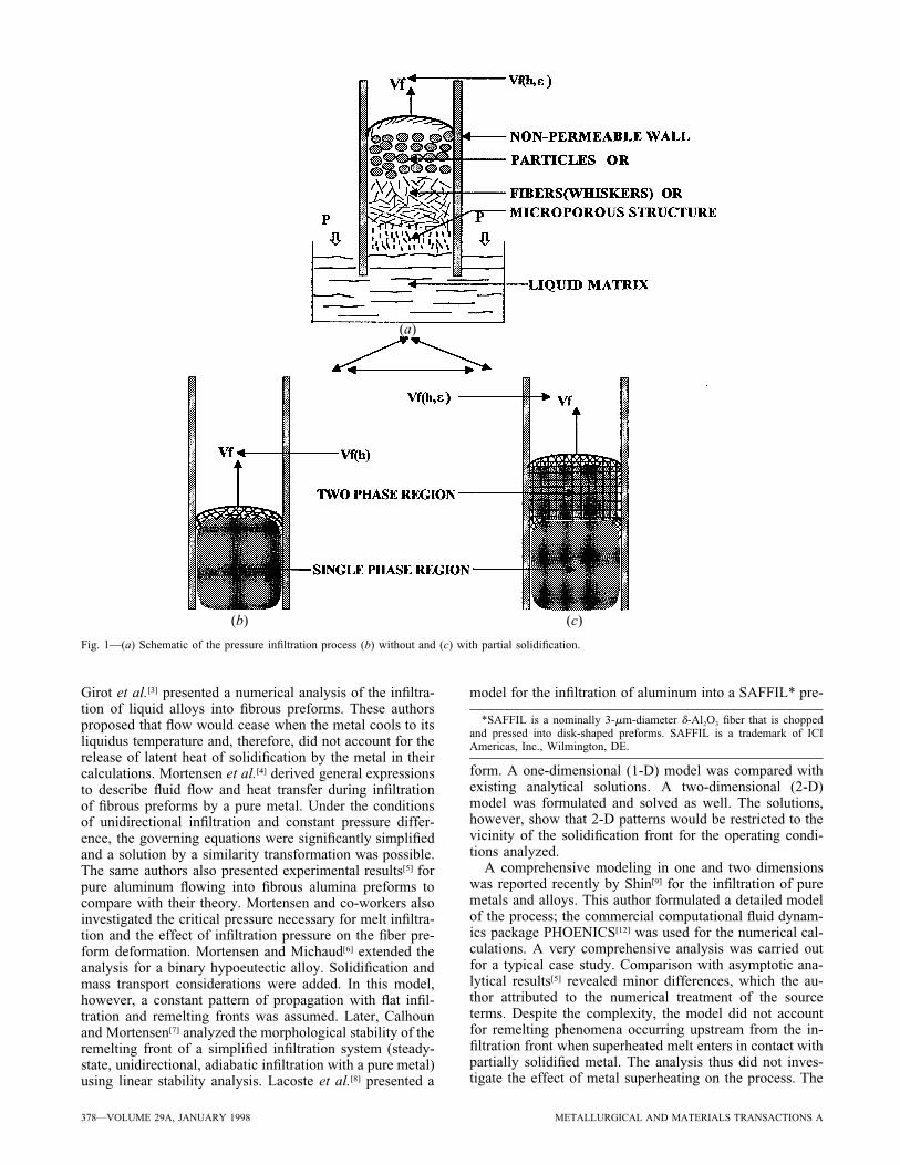
Fig. 2—Infiltration of pure Al into a SAFFIL fiber packed preform,without (solid line) and with (dashed line) solidification: (a) temperatureprofiles and (b) infiltration dynamics.
are as follows. The temperature-based formulation of theenergy equation requires conditions on temperature, veloc-ity, and heat transfer be specified in the vicinity of thesolid/liquid phase-change boundary. This causes a difficultyin the application of a fixed-grid numerical solution, as de-forming grids or transformed coordinate systems are re-quired to account for the position of the phase-change front.Thus, careful development of software including ad hocfeatures is often necessary. The enthalpy-based formulation,on the other hand, removes the need to satisfy the condi-tions at the phase-change front. This approach has threeadvantages: first, fixed-grid numerical solution schemes canbe employed; second, physical discontinuities encounteredin pure systems and eutectics can be avoided numerically;and third, the enthalpy method can be easily modified toaccommodate systems that solidify over a range of tem-perature and do not exhibit a well-defined solid/liquid in-terface. The main disadvantage of the enthalpy-basedformulation is that the location of the phase-change frontcannot be determined exactly. In systems with complicatedtransport processes close to the solid/liquid interface, thiscan represent a major problem.[24] For 1-D propagationproblems, however, the steep temperature profiles devel-oping at solidifying fronts can be efficiently resolved by
using a mapping transformation in a Lagrange formulation,with the front propagation being tracked by an additionalequation.[25]
Numerical solutions give detailed information, useful inunderstanding the effect of processing conditions on themicrostructure of infiltrated composites. In contrast to thesimilarity solutions, the numerical analyses are particularlyamenable to treating multidimensional (2-D) situations andsegregation dynamics (alloys).
To solve the governing equations, Eqs. [1] through [3],the system is discretized, with the maximum number ofcells limited by the hypothesis of continuum. The govern-ing equations are applied for each cell; the equations indifferences are derived by following a control volume for-mulation using upstream formulation for the convectiveterms and central differences for the conduction terms.Three different sets of equations result: the preform side(fibers and inert gas), the composite (preform and melt),and the cell where the infiltration front is located. The in-coming and outgoing fluids for the convection term for thecell where the front is located are melt and gas, respec-tively. The heat conduction takes place on one side of thiscell through the composite (fiber and melt) and on the otherside through the preform (fiber and gas). Therefore, the rateof energy exchange by conduction at the ‘‘front’’ cell isobtained by one-sided differences, which are used to obtainthe thermal gradient for each side. Different thermal con-ductivities are used for each side. A moving grid line isused to monitor the ‘‘filling’’ of the computational cellwhere the front is located. The results for temperature andenthalpy are updated after each iteration, while the solidfraction and infiltration velocity are updated only after fill-ing each computational cell. The numerical stability is en-sured by selecting the proper number of steps to ‘‘fill’’ acell (i.e., integration time-step).
IV. RESULTS AND DISCUSSION
Figures 2(a) and (b) show typical infiltration results forthe infiltration of superheated aluminum into a SAFFIL fi-ber-packed preform. As the superheated metal (1073 K)infiltrates the preform, it comes in contact with the packing(fibers) at a lower temperature, and therefore, the melt tem-perature decreases along the preform. As the infiltrationprocess continues, depending on the initial preform tem-perature, two significantly different behaviors are possible.For the preform preheated above the metal melting point(933 K, for aluminum), heat conduction progressivelysmoothes the temperature gradient to a point that the tran-sition between composite (metal and fibers) and preform(fibers and inert gas) becomes indistinguishable (it has beenindicated by an arrow in Figure 2(a)). When the preformpreheating temperature is below the metal melting point, onthe other hand, the temperature of the melt decreases untilit reaches its melting temperature, at which point partialsolidification characterized by a constant-temperature two-phase zone (cf. Figure 2(a)) can be observed. Two regionsare clearly distinguishable upstream and downstream fromthe infiltration front, which now can be clearly identifiedby a steep temperature gradient separating the metal infil-trated composite from the preform. As the infiltration pro-gresses through the preform, the two-phase zone expands,

382—VOLUME 29A, JANUARY 1998 METALLURGICAL AND MATERIALS TRANSACTIONS A
(a)
(b)
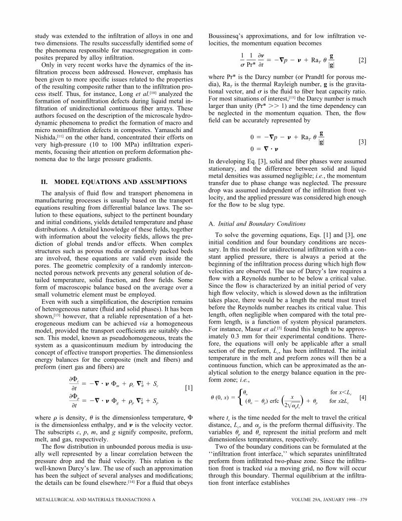
Fig. 3—Comparison of infiltration dynamics predicted analytically (solidline) and numerically (dashed line) in the (a) absence of solidification and(b) with partial solidification.
with its two boundaries, from here on referred to as the‘‘remelting’’ and ‘‘infiltration’’ fronts, exhibiting their owndynamics (cf. Figure 2(b)).
A comprehensive analysis of the process has been carriedout by Mortensen et al.[4] Their approach was to simplifythe governing equations for limiting conditions. The equa-tions thus simplified were solved in an analogous mannerto similarity solutions of moving fronts. The similarity var-iable was defined by Mortensen as
xx 5 [11]
=c t
where x and t represent the space and time variables, andR is a scaling factor. The scaling factor is chosen such asthe similarity variable is unitary at the infiltration front (i.e.,x 5 1 for x 5 Lf , where Lf is the axial location of theinfiltration front). Using this transformation, a closed formsolution of the governing equations, which showed satis-factory agreement with experimental results, was ob-tained.[5] The infiltration dynamics could then be describedby the scaling factor, c, as
2kDPin the absence of solidification=
mε[12]c 5
2DPin the presence of solidification=$
x 12xs smε 1~ !k k'
where DP is the pressure drop across the liquid column, kis the permeability of the uninfiltrated preform, m is thedynamic viscosity of the melt, and ε is the void fraction inthe uninfiltrated preform. Two additional variables are in-troduced for the case of solidification: k', the permeabilityof the two-phase zone; and xs, the location of the remeltingfront relative to the infiltration length (i.e., the two-phasezone length relative to the infiltration length would be 1 2xs). These equations, together with the flow description, Eq.[3], and the analytical expressions for the temperature pro-file, the length of the two-phase zone, and the solid fractionin the two-phase zone, describe the dynamics of the infil-tration process. The approach, however, relies on the hy-pothesis that the infiltration process can be described as aconstant-pattern process with a two-phase zone with con-stant solid fraction and length relative to the infiltrationlength (i.e., εs and xs are assumed to depend only on phys-ical properties and remain constant throughout the process).The comparison between the analytical predictions outlinedpreviously and the numerical results, presented next, showsthat εs and xs do not remain constant during infiltration.
A. Unidirectional Infiltration in the Absence ofSolidification
When the initial preform temperature is sufficiently high(or when the infiltration velocity is high), no solidificationof the matrix will occur. The permeability in the compositewill then remain constant. This simple case is consideredfirst in order to compare the present results with the ana-lytical model presented by Mortensen et al.[4] The infiltra-
tion dynamics are shown in Figure 3(a). The satisfactoryagreement existing between the numerical and analyticalpredictions validates the numerical model. This agreementcan be easily anticipated: the only hypothesis of the sin-gularity solution that is not verified in this situation is theconstant pressure drop across the infiltrated preform. In-deed, the hydrostatic correction will decrease the drivingforce and, therefore, the infiltration velocity. This effect, aswell as end effects, appears negligible, nevertheless.
B. Unidirectional Infiltration in the Presence ofSolidification
Numerical predictions can also be compared with the ex-perimental and analytical results for unidirectional adiabaticinfiltration with solidification. When the initial fiber pre-form temperature and the initial metal temperature (or theinfiltration velocity) are not sufficiently high as to avoidsolidification, solid metal will form upstream from the in-filtration front as a coating surrounding the packing fibers.The remaining liquid will flow further downstream, en-countering a new set of cold fibers, where additional solid-ification will take place in an analogous manner. Upstreamfrom the infiltration front, wherever solid and liquid metalcoexist, the temperature remains uniform at the metal melt-
METALLURGICAL AND MATERIALS TRANSACTIONS A VOLUME 29A, JANUARY 1998—383
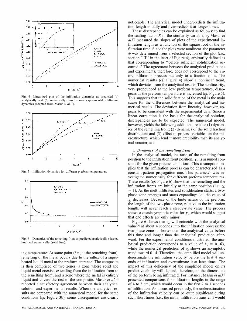
Fig. 4—Linearized plot of the infiltration dynamics as predicted (a)analytically and (b) numerically. Inset shows experimental infiltrationdynamics (adapted from Masur et al.[5]).
Fig. 5—Infiltration dynamics for different preform temperatures.
Fig. 6—Dynamics of the remelting front as predicted analytically (dashedline) and numerically (solid line).
ing temperature. At some point (i.e., at the remelting front),remelting of the metal occurs due to the influx of a super-heated liquid metal at the preform entrance. The compositeis then comprised of two zones: a zone where solid andliquid metal coexist, extending from the infiltration front tothe remelting front; and a zone where the metal is entirelyliquid and covers the rest of the composite. Masur et al.[5]
reported a satisfactory agreement between their analyticalsolution and experimental results. When the analytical re-sults are compared with the numerical model for the sameconditions (cf. Figure 3b), some discrepancies are clearly
noticeable. The analytical model underpredicts the infiltra-tion length initially and overpredicts it at longer times.
These discrepancies can be explained as follows: to findthe scaling factor R in the similarity variable, x, Masur etal.[5] measured the slopes of plots of the experimental in-filtration length as a function of the square root of the in-filtration time. Since the plots were nonlinear, the parameterc was determined from a selected section of the plot (i.e.,section ‘‘II’’ in the inset of Figure 4), arbitrarily defined asthat corresponding to ‘‘before sufficient solidification oc-curred.’’ The agreement between the analytical predictionsand experiments, therefore, does not correspond to the en-tire infiltration process but only to a fraction of it. Thenumerical results (cf. Figure 4) show a nonlinear trend,which deviates from the analytical results. The nonlinearity,very pronounced at the low preform temperatures, disap-pears as the preform temperature is increased (cf. Figure 5).This suggests that the solidification of the metal is the maincause for the differences between the analytical and nu-merical results. The deviation from linearity, however, ap-pears to be consistent with the experimental data. Since alinear correlation is the basis for the analytical solution,discrepancies are to be expected. The numerical model,however, yields the following additional results: (1) dynam-ics of the remelting front; (2) dynamics of the solid fractiondistribution; and (3) effect of process variables on the mi-crostructure, which lend it more credibility than its analyt-ical counterpart.
1. Dynamics of the remelting frontIn the analytical model, the ratio of the remelting front
position to the infiltration front position, xs, is assumed con-stant for the given process conditions. This assumption im-plies that the infiltration process can be characterized as aconstant-pattern propagation one. This parameter was in-vestigated numerically for different preform temperatures.These results (cf. Figure 6) show that the remelting and theinfiltration fronts are initially at the same position (i.e., xs
5 1). As the melt infiltrates and solidification starts, a two-phase zone emerges and starts expanding: i.e., the value ofxs decreases. Because of the finite nature of the preform,the length of the two-phase zone, relative to the infiltrationlength, will never reach a steady-state value. The processshows a quasiasymptotic value for xs, which would suggestthat end effects are only minor.
Figure 6 shows that xs will coincide with the analyticalvalue[4] at about 4 seconds into the infiltration process: thetwo-phase zone is shorter than the analytical value beforethis time and longer than the analytical prediction after-ward. For the experimental conditions illustrated, the ana-lytical prediction corresponds to a value of xs 5 0.163,while the numerical prediction of xs shows an asymptotictrend toward 0.14. Therefore, the simplified model will un-derestimate the infiltration velocity before the first 4 sec-onds of infiltration and overestimate it at later times. Theimpact of this deficiency of the simplified model on itspredictive ability will depend, therefore, on the dimensionsof the preform being infiltrated. For instance, Masur et al.[5]
presented comparisons for infiltration lengths in the rangeof 4 to 5 cm, which would occur in the first 2 to 3 secondsof infiltration. As discussed previously, the underestimationof the infiltration velocity can be quite significant duringsuch short times (i.e., the initial infiltration transients would

384—VOLUME 29A, JANUARY 1998 METALLURGICAL AND MATERIALS TRANSACTIONS A
Fig. 7—Dynamics of the solid fraction at the infiltration front.
Fig. 8—Solid fraction distribution as predicted analytically (dashed line)and numerically.
Fig. 9—Effect of the superheating on the solid fraction distribution.
Fig. 10—Effect of the applied pressure on the solid fraction distribution.
not have disappeared during the first few seconds of infil-tration).
2. Dynamics of the solid fraction distributionWhile the solid fraction at the infiltration front (cf. Fig-
ure 7) reaches a constant value very rapidly, it is not con-stant in the two-phase zone, as shown in Figure 8 for twotypical infiltration times. The analytical model, on theother hand, assumes a constant solid fraction value for thetwo-phase zone. For the process conditions illustrated, thenumerical result is approximately a solid fraction of 14pct at the infiltration front against an analytically predictedconstant solid fraction of 19.2 pct. If the dynamics of thesolid fraction are investigated in more detail, one can ob-serve that during the early stages (; 3 seconds) of infil-tration, the maximum solid fraction is lower than the
analytical prediction. As infiltration continues, the maxi-mum solid fraction exceeds the analytical prediction. Dur-ing this second stage, the average solid fraction willapproximately correspond with the constant value pre-dicted by the simplified model. However, because of theinitial lower solid fraction, the permeability of the preformwill be underestimated during the infiltration of the first 6cm. This will, in turn, result in an underestimation of theinfiltration rate. Similarly, at the later stages of the infil-tration process, when sufficient solid has formed, and themaximum and the average solid fractions are higher thanthose predicted analytically, the analytical model willoverestimate the overall permeability of the preform, aswell as the infiltration rate.
3. Effect of process parameters on the solid fractiondistribution
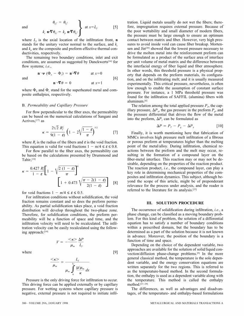
The effect of the degree of melt superheating on the solidfraction distribution along the specimen length is illustratedin Figure 9. This figure shows the solid fraction distribu-tion, for identical infiltration lengths, for different degreesof superheating. The initial preform temperature, total ap-plied pressure, and fiber volume fraction were kept constantfor two melt temperatures: 1073 and 948 K. This figureshows that the length of the two-phase zone and the averagesolid fraction in this zone decrease with increasing super-heating. In other words, the extent of superheating will af-fect not only the remelting front position but also the solidfraction distribution in the two-phase zone.
A similar investigation was carried out on the effect ofthe applied pressure on the solid fraction distribution. Theinitial preform and melt temperatures, as well as the fibervolume fraction, were kept constant for the comparisonshown in Figure 10. This figure presents the solid fractiondistribution for different applied pressures, for the same in-filtration length. The results show that the applied pressuredoes not significantly influence the remelting front position,but it considerably affects the solid fraction distribution. Athigher pressure, because of the faster superficial velocity,the solid fraction in the two-phase zone is significantlylower than that observed at the lower pressure. However,only a minor increase in the length of the two-phase zoneoccurs. The analytical model, on the other hand, does notaccount for the effects of the degree of superheating or theapplied pressure on the solid fraction distribution. The solidfraction distribution is a very important parameter, which

METALLURGICAL AND MATERIALS TRANSACTIONS A VOLUME 29A, JANUARY 1998—385
will influence the microstructure and the micro/macro-segregation of solutes during pressure infiltration casting ofmetallic alloys.
V. CONCLUSIONS
A mathematical model for the dynamics of pressure in-filtration processes has been formulated and solved numer-ically. The numerical solution is reliable and robust and canaccount for end effects and structural dynamics. The nu-merical solution is compared against a classical similaritysolution. Both models are in agreement for the homoge-neous infiltration in the absence of phase-change effects,where end effects appeared negligible and the assumptionof constant-pattern propagation was valid. For conditionsthat result in partial solidification (and, eventually, subse-quent plugging), the numerical and analytical solutions dif-fer substantially. Most of the discrepancies are caused bythe assumption of a constant-pattern propagation made inthe similarity solution. Actual infiltration processes nevershow constant pattern propagation. The numerical solutionshows the presence of significant end effects and an un-steady mode of propagation, in contrast to the uniform solidfraction and constant ratio between the infiltration and re-melting fronts, as assumed by the analytical solution. Al-though the overall infiltration dynamics are not significantlyaffected by these differences, the related issues such as 2-D effects, segregation, and alloy infiltration can be expectedto be markedly influenced.
Summarizing, the numerical analysis, presented previ-ously, leads to the following conclusions.1. End effects might become preponderant during the ini-
tial and final stages of the infiltration, diminishing thevalue of asymptotic analyses as reliable design tools andrendering them only useful indicative tools.
2. Although heat conduction in the preform might be neg-ligible in estimating the temperature profile, it cannot beneglected when the matrix and the preform have similarconductivities. The steep thermal gradients existingdownstream from the solidifying front may combinewith low thermal conductivities to significantly influencethe infiltration dynamics.
3. The two-phase zone dynamics are very sensitive to theoccurrence of partial solidification.
4. The effect of the degree of superheating on the infiltra-tion dynamics is not as significant as that of the preformtemperature. The degree of superheating, however, af-fects the length of the two-phase zone and the solid frac-tion distribution.
5. The applied pressure has a negligible effect on the lengthof the two-phase zone, but it influences the solid fractiondistribution substantially.
ACKNOWLEDGMENTS
Support provided by the Processing Science and Tech-nology Branch, NASA–Lewis Research Center (Cleveland,OH), is gratefully acknowledged. The authors are alsothankful to the reviewers for their careful reading and val-uable suggestions.
REFERENCES
1. S. Nagata and K. Matsuda: Trans. Jpn. Foundrymen’s Soc., 1982,vol. 2, pp. 616-20.
2. G.P. Martins, D.L. Olson, and G.R. Edwards: Metall. Trans. B, 1988,vol. 19B, pp. 95-101.
3. F.A. Girot, R. Fedon, J.M. Quenisset, and R. Naslain: J. ReinforcedPlastics Composites, 1990, vol. 9, pp. 456-69.
4. A. Mortensen, L.J. Masur, J.A. Cornie, and M.C. Flemings: Metall.Trans. A, 1989, vol. 20A, pp. 2535-47.
5. L.J. Masur, A. Mortensen, J.A. Cornie, and M.C. Flemings: Metall.Trans. A, 1989, vol. 20A, pp. 2549-57.
6. A. Mortensen and V. Michaud: Metall. Trans. A, 1990, vol. 21A, pp.2059-72.
7. R.B. Calhoun and A. Mortensen: Metall. Trans. A, 1992, vol. 23A,pp. 2291-99.
8. E. Lacoste, M. Aboulfatah, M. Danis, and F. Girot: Metall. Trans. A,1993, vol. 24A, pp. 2667-78.
9. Kwan-Hong Shin: Ph.D. Thesis, The University of Iowa, Iowa City,IA, 1993.
10. S. Long, Z. Zhang, and H.M. Flower: Acta Metall. Mater., 1994, vol.42 (4), pp. 1389-97.
11. T. Yamauchi and Y. Nishida: Acta Metall. Mater., 1995, vol. 43 (4),pp. 1313-21.
12. D.B. Spalding: in Computer Simulation for Fluid, Heat and MassTransfer in Reciprocation Engines, Hemisphere Publishing Corp.,New York, NY, 1989, [pp. 383-455.]
13. D. Vortmeyer, K.J. Dietrich, and K.O. Ring: Adv. Chem. Ser., 1974,vol. 133, pp. 588-99.
14. J.E. Gatica, H.J. Viljoen, and V. Hlavacek: Chem. Eng. Sci., 1989,vol. 44 (9), pp. 1853-70.
15. J.M. Straus: J. Fluid Mech., 1974, vol. 64 (1), pp. 51-63.16. P.V. Danckwerts: Chem. Eng. Sci., 1953, vol. 2 (1), pp. 1-18.17. A.S. Sangani and A. Acrivos: Int. J. Multiphase Flow, 1982, vol. 8,
pp. 193-206.18. J.E. Drummond and M.I. Tahir: Int. J. Multiphase Flow, 1984, vol.
10, pp. 515-40.19. S.K. Datta, N. Simhai, S.N. Tewari, J.E. Gatica, and M. Singh: Metall.
Mater. Trans. A, 1996, vol. 27A, pp. 3669-74.20. A. Mortensen and I. Jin: Int. Mater. Rev., 1992, vol. 37 (3), pp.
101-28.21. D. Longworth: in Moving Boundary Problems in Heat Flow and
Diffusion, J.R. Ockendon and W.R. Hodkin, eds., Clarendon Press,Oxford, United Kingdom, 1975.
22. V.R. Voller and M. Cross: Int. J. Heat Transfer, 1981, vol. 24, pp.5454-56.
23. V.R. Voller, M. Cross, and N.C. Markatas: Int. J. Num. Methods Eng.,1987, vol. 24, pp. 271-84.
24. J.E. Gatica, P.A. Dimitriou, J.A. Puszynski, and V. Hlavacek: Int. J.SHS, 1995, vol. 4 (2), pp. 123-36.
25. G.R. Cappleman, J.F. Watts, and T.W. Clyne: J. Mater. Sci., 1985,vol. 20, pp. 2159-68.