Breakdown pressures due to infiltration and exclusion in finite length boreholes
8
1. INTRODUCTION The breakdown pressure is the critical pressure where failure occurs during borehole pressurization. Numerous attempts have been made to forecast the magnitude of breakdown pressure by analytical, semi-analytical and numerical approaches [1, 2, 3]. Initial attempts focused on an analytical formula to predict the breakdown pressure in impermeable rocks [4]. Subsequent analyses extended this formula for fluid pressurization in permeable rocks [5]. In this solution thermoelastic stressing was used as an analog to represent fluid pressurization[6]. The results from these two approaches and for these two conditions – impermeable versus permeable borehole walls- show two different bounding values: The breakdown pressure in permeable rock is always lower than that in impermeable rock. This approach provides a pathway to explore pressurization rate effect on the breakdown process. Experimental approaches have shown that that a higher pressurization rates, the breakdown pressure is also elevated. [7, 8, 9, 10]. This observation may be explained as the influence of a pressure diffusion mechanism [11, 12], that requires a critical diffusive pressure to envelop a critical flaw length in the borehole wall. All these approaches rely on Terzaghi's theory of effective stress [13], which predicts that failure will ARMA 13-700 Breakdown pressures due to infiltration and exclusion in finite length boreholes Gan Q. Energy and Mineral Engineering, G3 center and EMS Energy Institute, The Pennsylvania State University, University Park, PA 16802 Alpern, J.S., Marone, C. Geosciences, G3 center and EMS Energy, Institute, The Pennsylvania State University, University Park, PA 16802 Connolly, P. Chevron Energy Technology Company, Houston, TX 77002 Elsworth, D. Energy and Mineral Engineering, G3 center and EMS Energy Institute, The Pennsylvania State University, University Park, PA 16802 Copyright 2013 ARMA, American Rock Mechanics Association This paper was prepared for presentation at the 47 th US Rock Mechanics / Geomechanics Symposium held in San Francisco, CA, USA, 23-26 June 2013. This paper was selected for presentation at the symposium by an ARMA Technical Program Committee based on a technical and critical review of the paper by a minimum of two technical reviewers. The material, as presented, does not necessarily reflect any position of ARMA, its officers, or members. Electronic reproduction, distribution, or storage of any part of this paper for commercial purposes without the written consent of ARMA is prohibited. Permission to reproduce in print is restricted to an abstract of not more than 200 words; illustrations may not be copied. The abstract must contain conspicuous acknowledgement of where and by whom the paper was presented. ABSTRACT: The theory of effective stress suggests that the breakdown pressure of a borehole should be a function of ambient stress and strength of the rock, alone. However, our experiments on finite boreholes indicate that the breakdown pressure is a strong function of fracturing fluid type/state as well. We explain reasons for this behavior including the roles of different fluid types and state in controlling the breakdown process. We propose that the fluid interfacial tension controls whether fluid invades pore space at the borehole wall and this in turn changes the local stress regime hence breakdown pressure. Interfacial tension is modulated by fluid state, as sub- or supercritical, and thus gas type and state influence the breakdown pressure. We develop expressions for the breakdown pressure in circular section boreholes of both infinite and finite length to validate our hypothesis. Importantly, the analysis accommodates the influence of fluid infiltration or exclusion into the borehole wall. For the development of a radial hydraulic fracture (longitudinal failure) the solutions are those of Detournay and Cheng (1992) and show a higher breakdown pressure for impermeable (Hubbert and Willis, 1957) relative to permeable (Haimson and Fairhurst, 1967). A similar difference in breakdown pressure exists for failure on a transverse fracture that is perpendicular to the borehole axis, in this case modulated by a parameter / (1 ) ν η α ν = - , where ν is Poisson ratio and α the Biot coefficient. A numerical solution is obtained for this finite length borehole to define tensile stresses at the borehole wall due to a decomposed loading from an external confining stress and interior pressurization. Numerical results agree with the breakdown pressure records recovered for experiments for pressurization by CO 2 and argon:
Transcript of Breakdown pressures due to infiltration and exclusion in finite length boreholes
1. INTRODUCTION
The breakdown pressure is the critical pressure where
failure occurs during borehole pressurization. Numerous
attempts have been made to forecast the magnitude of breakdown pressure by analytical, semi-analytical and
numerical approaches [1, 2, 3].
Initial attempts focused on an analytical formula to predict the breakdown pressure in impermeable rocks
[4]. Subsequent analyses extended this formula for fluid
pressurization in permeable rocks [5]. In this solution thermoelastic stressing was used as an analog to
represent fluid pressurization[6]. The results from these
two approaches and for these two conditions –impermeable versus permeable borehole walls- show
two different bounding values: The breakdown pressure
in permeable rock is always lower than that in impermeable rock.
This approach provides a pathway to explore
pressurization rate effect on the breakdown process. Experimental approaches have shown that that a higher
pressurization rates, the breakdown pressure is also
elevated. [7, 8, 9, 10]. This observation may be explained as the influence of a pressure diffusion
mechanism [11, 12], that requires a critical diffusive
pressure to envelop a critical flaw length in the borehole wall.
All these approaches rely on Terzaghi's theory of
effective stress [13], which predicts that failure will
ARMA 13-700
Breakdown pressures due to infiltration and exclusion in
finite length boreholes
Gan Q.
Energy and Mineral Engineering, G3 center and EMS Energy Institute, The Pennsylvania State University, University
Park, PA 16802
Alpern, J.S., Marone, C.
Geosciences, G3 center and EMS Energy, Institute, The Pennsylvania State University, University Park, PA 16802
Connolly, P.
Chevron Energy Technology Company, Houston, TX 77002
Elsworth, D.
Energy and Mineral Engineering, G3 center and EMS Energy Institute, The Pennsylvania State University, University
Park, PA 16802
Copyright 2013 ARMA, American Rock Mechanics Association
This paper was prepared for presentation at the 47th US Rock Mechanics / Geomechanics Symposium held in San Francisco, CA, USA, 23-26
June 2013.
This paper was selected for presentation at the symposium by an ARMA Technical Program Committee based on a technical and critical review of the paper by a minimum of two technical reviewers. The material, as presented, does not necessarily reflect any position of ARMA, its officers, or members. Electronic reproduction, distribution, or storage of any part of this paper for commercial purposes without the written consent of ARMA is prohibited. Permission to reproduce in print is restricted to an abstract of not more than 200 words; illustrations may not be copied. The abstract must contain conspicuous acknowledgement of where and by whom the paper was presented.
ABSTRACT: The theory of effective stress suggests that the breakdown pressure of a borehole should be a function of ambient
stress and strength of the rock, alone. However, our experiments on finite boreholes indicate that the breakdown pressure is a strong function of fracturing fluid type/state as well. We explain reasons for this behavior including the roles of different fluid types and
state in controlling the breakdown process. We propose that the fluid interfacial tension controls whether fluid invades pore space
at the borehole wall and this in turn changes the local stress regime hence breakdown pressure. Interfacial tension is modulated by
fluid state, as sub- or supercritical, and thus gas type and state influence the breakdown pressure. We develop expressions for the
breakdown pressure in circular section boreholes of both infinite and finite length to validate our hypothesis. Importantly, the
analysis accommodates the influence of fluid infiltration or exclusion into the borehole wall. For the development of a radial
hydraulic fracture (longitudinal failure) the solutions are those of Detournay and Cheng (1992) and show a higher breakdown
pressure for impermeable (Hubbert and Willis, 1957) relative to permeable (Haimson and Fairhurst, 1967). A similar difference in breakdown pressure exists for failure on a transverse fracture that is perpendicular to the borehole axis, in this case modulated by a
parameter / (1 )νη αν= − , where ν is Poisson ratio and α the Biot coefficient. A numerical solution is obtained for this finite
length borehole to define tensile stresses at the borehole wall due to a decomposed loading from an external confining stress and
interior pressurization. Numerical results agree with the breakdown pressure records recovered for experiments for pressurization
by CO2 and argon:
occur when the effective stress is equal to the tensile
strength. Furthermore, this suggests that breakdown pressures should be invariant of fluid type (composition)
or state (gas or liquid) since failure is mediated by
effective stress, alone. However recent results [18] suggest that fluid composition and/or state may
influence breakdown pressure in an important manner.
In this work, we develop an approach to explain the role of fluid composition/state on breakdown pressure based
on prior observations of permeable versus impermeable
borehole walls. In this approach the physical characteristics of the borehole remain the same for all
fluid compositions, but the feasibility of the fluid either
invading the borehole wall or being excluded from it changes with fluid state (subcritical or supercritical). We
develop an approach based on Biot effective stress, to
define breakdown pressure for supercritical/subcritical gas fracturing. The critical entry-pore pressure is
governed by fluid interfacial tension [14, 15, 16, 17],
and the subcritical fluid breakdown pressure is shown to scales with critical pressure. These breakdown pressures
agree with experimental observations.
2. EXPERIMENTAL OBSERVATIONS
Fracturing experiments have been conducted on a
homogeneous cube of Polymethyl methacralate (PMMA) [18]. The pressurized fracturing fluid is
injected through a drilled channel, which is analog to the
borehole. The borehole's diameter was 3.66 mm; the cubes were under biaxial and triaxial stress load. The
borehole is typically parallel to the minimum principal
stress.
Six different fracturing fluids are injected in separate
experiments under same room temperature, and the
borehole is pressurized to fail. These fluids include helium (He), nitrogen (N2), carbon dioxide (CO2), argon
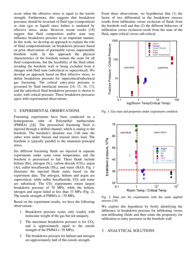
(Ar), sulfur hexafluoride (SF6), and water (H2O). Fig. 1
illustrates the injected fluids states based on the experiment data. The nitrogen, helium and argon are
supercritical, while sulfur hexafluoride, CO2 and water
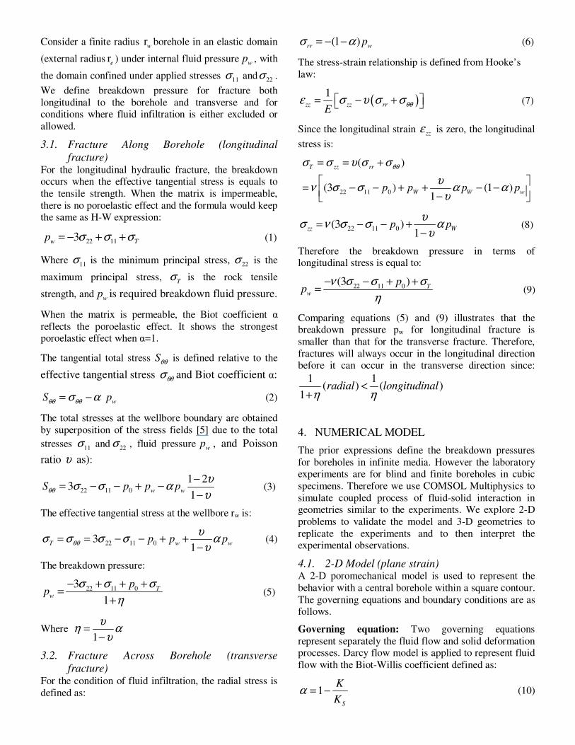
are subcritical. The CO2 experiments return largest breakdown pressure of 70 MPa, while the helium,
nitrogen and argon failed at less than 33 MPa (Fig. 2).
The tensile strength of PMMA is ~70 MPa.
Based on the experiment results, we have the following
observations:
1. Breakdown pressure scales only weakly with molecular weight of the gas but not uniquely.
2. The maximum breakdown pressure is for CO2,
and is approximately equal to the tensile strength of the PMMA (~70 MPa).
3. The breakdown pressure for helium and nitrogen
are approximately half of this tensile strength.
From these observations, we hypothesize that (1) the
factor of two differential in the breakdown stresses results from infiltration versus exclusion of fluids from
the borehole wall and that (2) the different behaviors of
infiltration versus exclusion result from the state of the fluid, super-critical versus sub-critical.
1
10
100
1000
0.1 1 10 100
HeliumNitrogenCarbon DioxideArgonWaterSulfer Hexafluoride
Fra
ctu
re P
ressure
/ C
ritical P
ressure
log(Room Temp/Critical Temp)
subcritical superticial
Fig. 1. Gas state and properties under experiment condition
Fig. 2. Data sets for experiments with the same applied stresses [18]
We explore this hypothesis by firstly identifying the
difference in breakdown pressure for infiltrating versus
non-infiltrating fluids and then relate the propensity for infiltration to entry pressures in the borehole wall.
3. ANALYTICAL SOLUTIONS
Consider a finite radius rw
borehole in an elastic domain
(external radius re) under internal fluid pressure
wp , with
the domain confined under applied stresses 11σ and 22σ .
We define breakdown pressure for fracture both
longitudinal to the borehole and transverse and for conditions where fluid infiltration is either excluded or
allowed.
3.1. Fracture Along Borehole (longitudinal
fracture) For the longitudinal hydraulic fracture, the breakdown occurs when the effective tangential stress is equals to
the tensile strength. When the matrix is impermeable,
there is no poroelastic effect and the formula would keep the same as H-W expression:
22 113w Tp σ σ σ= − + + (1)
Where 11σ is the minimum principal stress, 22σ is the
maximum principal stress, T
σ is the rock tensile
strength, andw
p is required breakdown fluid pressure.
When the matrix is permeable, the Biot coefficient α
reflects the poroelastic effect. It shows the strongest poroelastic effect when α=1.
The tangential total stress Sθθ is defined relative to the
effective tangential stress θθσ and Biot coefficient α:
wS pθθ θθσ α= − � (2)
The total stresses at the wellbore boundary are obtained
by superposition of the stress fields [5] due to the total
stresses 11σ and 22σ , fluid pressurew
p , and Poisson
ratio υ as):
22 11 0
1 23
1w wS p p pθθ
υσ σ α
υ
−= − − + −
− (3)
The effective tangential stress at the wellbore rw is:
22 11 031
T w wp p pθθ
υσ σ σ σ α
υ= = − − + +
− (4)
The breakdown pressure:
22 11 03
1
Tw
pp
σ σ σ
η
− + + +=
+ (5)
Where 1
υη α
υ=
−
3.2. Fracture Across Borehole (transverse
fracture) For the condition of fluid infiltration, the radial stress is
defined as:
(1 )rr w
pσ α= − − (6)
The stress-strain relationship is defined from Hooke’s
law:
( )1
zz zz rrE
θθε σ υ σ σ= − + (7)
Since the longitudinal strain zz
ε is zero, the longitudinal
stress is:
22 11 0
( )
(3 ) (1 )1
T zz rr
W W wp p p p
θθσ σ υ σ σ
υν σ σ α α
υ
= = +
= − − + + − − −
22 11 0(3 )1
zz Wp pυ
σ ν σ σ αυ
= − − +−
(8)
Therefore the breakdown pressure in terms of longitudinal stress is equal to:
22 11 0(3 )
Tw
pp
ν σ σ σ
η
− − + += (9)
Comparing equations (5) and (9) illustrates that the breakdown pressure pw for longitudinal fracture is
smaller than that for the transverse fracture. Therefore,
fractures will always occur in the longitudinal direction before it can occur in the transverse direction since:
1 1( ) ( )
1radial longitudinal
η η<
+
4. NUMERICAL MODEL
The prior expressions define the breakdown pressures
for boreholes in infinite media. However the laboratory experiments are for blind and finite boreholes in cubic
specimens. Therefore we use COMSOL Multiphysics to
simulate coupled process of fluid-solid interaction in geometries similar to the experiments. We explore 2-D
problems to validate the model and 3-D geometries to
replicate the experiments and to then interpret the experimental observations.
4.1. 2-D Model (plane strain) A 2-D poromechanical model is used to represent the
behavior with a central borehole within a square contour.
The governing equations and boundary conditions are as follows.
Governing equation: Two governing equations
represent separately the fluid flow and solid deformation processes. Darcy flow model is applied to represent fluid
flow with the Biot-Willis coefficient defined as:
1S
K
Kα = − (10)
where S
K and K are identified as the grain and solid
bulk modulus.
The flow equation is:
ss
kHS H Q
tα
µ
∂+ ∇ − ∇ = − ∂
� (11)
Where s
Q defines the time rate of change of volumetric
strain from the equation for solid displacements:
s *( ( , ) ( , ))x yQ d u t d v tα= + (12)
where the volume fraction of liquid changes with
deformationsx
u andy
v . Sα is specific storage defined
by coefficients of Young’s modulus E, and the
Poisson ratio υ [19].
The solid deformation equation is:
2 ( )2(1 ) 2(1 )(1 2 )
b f
E Eu u g Hα ρ
υ υ υ∇ + ∇ ∇ = ∇
+ + −�
where E is Young’s modulus, u is the displacement
vector composed of orthogonal displacements u
and v (m). The right hand side term b f
gα ρ
represents the fluid-to-structure coupling term.
Boundary Conditions:
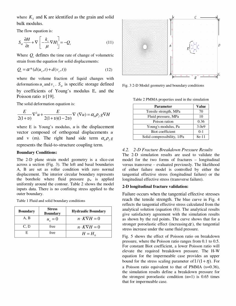
The 2-D plane strain model geometry is a slice-cut across a section (Fig. 3). The left and basal boundaries
A, B are set as roller condition with zero normal
displacement. The interior circular boundary represents the borehole where fluid pressure pw is applied
uniformly around the contour. Table 2 shows the model
inputs data. There is no confining stress applied to the outer boundary.
Table 1 Fluid and solid boundary conditions
Fig. 3 2-D Model geometry and boundary conditions
Table 2 PMMA properties used in the simulation
Parameter Value
Tensile strength, MPa 70
Fluid pressure, MPa 10
Poison ration 0.36
Young's modulus, Pa 3.0e9
Biot coefficient 0-1
Solid compressibility, 1/Pa 8e-11
4.2. 2-D Fracture Breakdown Pressure Results The 2-D simulation results are used to validate the
model for the two forms of fractures – longitudinal
versus transverse – evaluated previously. The likelihood of either failure model is controlled by either the
tangential effective stress (longitudinal failure) or the
longitudinal effective stress (transverse failure).
2-D longitudinal fracture validation:
Failure occurs when the tangential effective stresses
reach the tensile strength. The blue curve in Fig. 4
reflects the tangential effective stress calculated from the
analytical solution (equation (8)). The analytical results
give satisfactory agreement with the simulation results as shown by the red points. The curve shows that for a
stronger poroelastic effect (increasingα ), the tangential
stress increase under the same fluid pressure.
Fig. 5 shows the effect of Poisson ratio on breakdown
pressure, where the Poisson ratio ranges from 0.1 to 0.5. For constant Biot coefficient, a lower Poisson ratio will
elevate the required breakdown pressure. The H-W
equation for the impermeable case provides an upper
bound for the stress scaling parameter of1/ (1+η) . For
a Poisson ratio equivalent to that of PMMA (υ=0.36),
the simulation results define a breakdown pressure for the strongest poroelastic condition (α=1) is 0.65 times
that for impermeable case.
Boundary Stress
Boundary Hydraulic Boundary
A, B 0n
u =
0n K H⋅ ∇ =
C, D free 0n K H⋅ ∇ = E free
0H H=
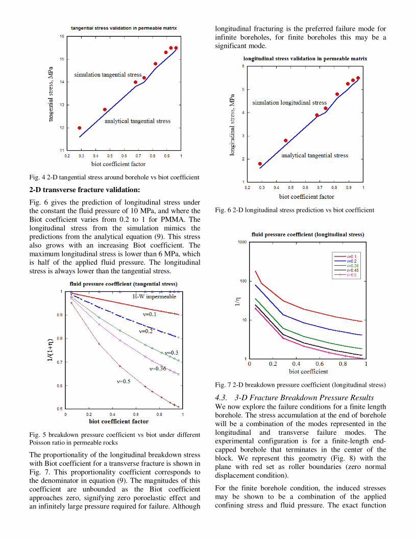
Fig. 4 2-D tangential stress around borehole vs biot coefficient
2-D transverse fracture validation:
Fig. 6 gives the prediction of longitudinal stress under the constant the fluid pressure of 10 MPa, and where the
Biot coefficient varies from 0.2 to 1 for PMMA. The
longitudinal stress from the simulation mimics the predictions from the analytical equation (9). This stress
also grows with an increasing Biot coefficient. The
maximum longitudinal stress is lower than 6 MPa, which is half of the applied fluid pressure. The longitudinal
stress is always lower than the tangential stress.
Fig. 5 breakdown pressure coefficient vs biot under different
Poisson ratio in permeable rocks
The proportionality of the longitudinal breakdown stress
with Biot coefficient for a transverse fracture is shown in
Fig. 7. This proportionality coefficient corresponds to the denominator in equation (9). The magnitudes of this
coefficient are unbounded as the Biot coefficient
approaches zero, signifying zero poroelastic effect and an infinitely large pressure required for failure. Although
longitudinal fracturing is the preferred failure mode for
infinite boreholes, for finite boreholes this may be a significant mode.
Fig. 6 2-D longitudinal stress prediction vs biot coefficient
Fig. 7 2-D breakdown pressure coefficient (longitudinal stress)
4.3. 3-D Fracture Breakdown Pressure Results We now explore the failure conditions for a finite length borehole. The stress accumulation at the end of borehole
will be a combination of the modes represented in the
longitudinal and transverse failure modes. The experimental configuration is for a finite-length end-
capped borehole that terminates in the center of the
block. We represent this geometry (Fig. 8) with the plane with red set as roller boundaries (zero normal
displacement condition).
For the finite borehole condition, the induced stresses may be shown to be a combination of the applied
confining stress and fluid pressure. The exact function
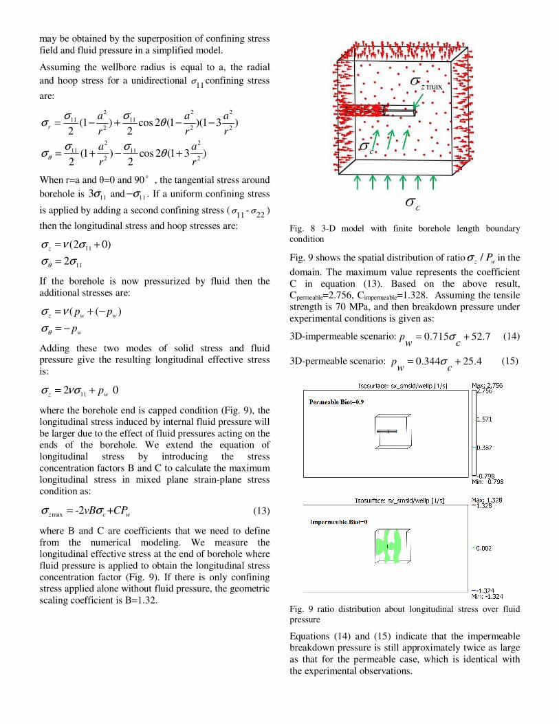
may be obtained by the superposition of confining stress
field and fluid pressure in a simplified model.
Assuming the wellbore radius is equal to a, the radial
and hoop stress for a unidirectional 11
σ confining stress
are:
2 2 2
11 11
2 2 2
2 2
11 11
2 2
(1 ) cos 2 (1 )(1 3 )2 2
(1 ) cos 2 (1 3 )2 2
r
a a a
r r r
a a
r rθ
σ σσ θ
σ σσ θ
= − + − −
= + − +
When r=a and θ=0 and 90°, the tangential stress around
borehole is 11
3σ and11
σ− . If a uniform confining stress
is applied by adding a second confining stress (11
σ -22
σ )
then the longitudinal stress and hoop stresses are:
11
11
(2 0)
2
z
θ
σ ν σ
σ σ
= +
=
If the borehole is now pressurized by fluid then the
additional stresses are:
( ( )z w w
w
p p
pθ
σ ν
σ
= + −
= −
Adding these two modes of solid stress and fluid pressure give the resulting longitudinal effective stress
is:
112 0
z wpσ νσ= + �
where the borehole end is capped condition (Fig. 9), the longitudinal stress induced by internal fluid pressure will
be larger due to the effect of fluid pressures acting on the ends of the borehole. We extend the equation of
longitudinal stress by introducing the stress
concentration factors B and C to calculate the maximum longitudinal stress in mixed plane strain-plane stress
condition as:
max -2 +z c wvB CPσ σ= (13)
where B and C are coefficients that we need to define
from the numerical modeling. We measure the longitudinal effective stress at the end of borehole where
fluid pressure is applied to obtain the longitudinal stress
concentration factor (Fig. 9). If there is only confining stress applied alone without fluid pressure, the geometric
scaling coefficient is B=1.32.
Fig. 8 3-D model with finite borehole length boundary
condition
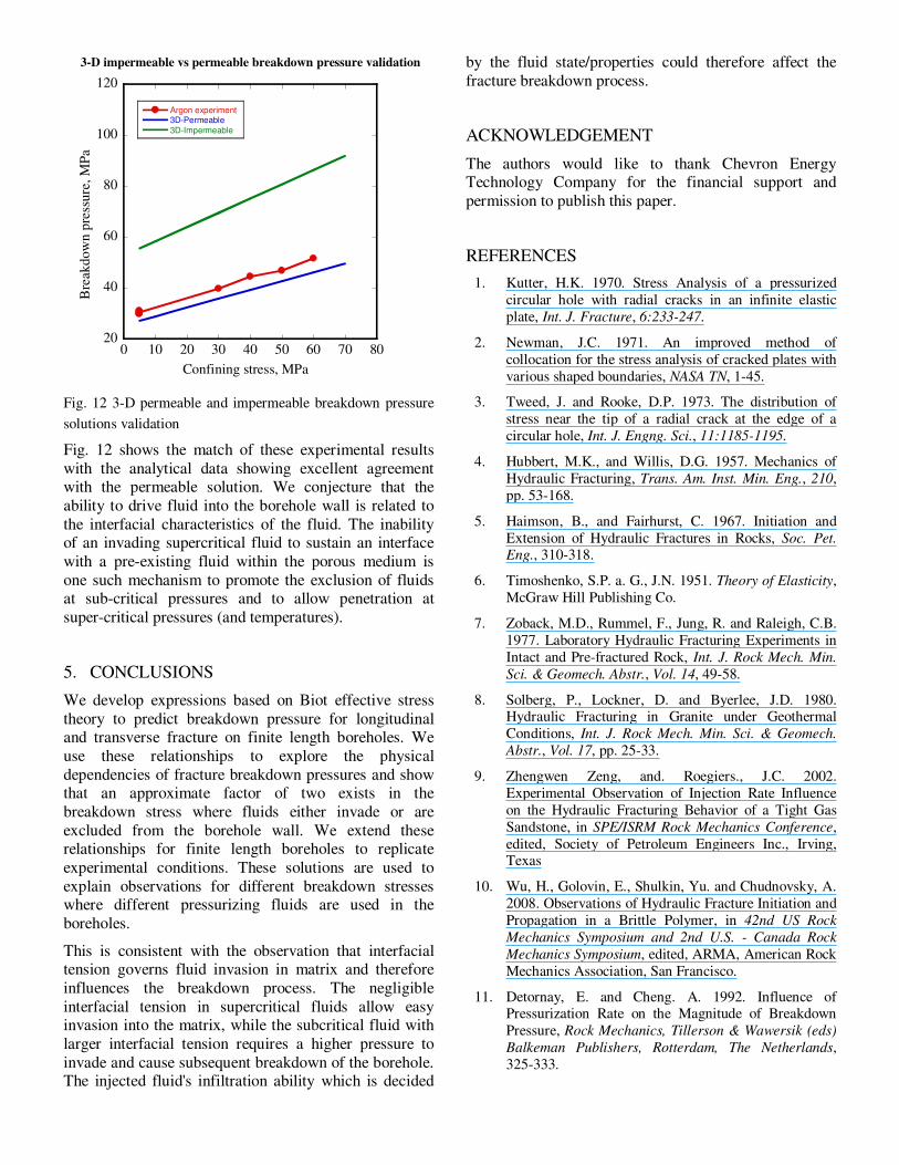
Fig. 9 shows the spatial distribution of ratio /z w
Pσ in the
domain. The maximum value represents the coefficient
C in equation (13). Based on the above result, Cpermeable=2.756, Cimpermeable=1.328. Assuming the tensile
strength is 70 MPa, and then breakdown pressure under
experimental conditions is given as:
3D-impermeable scenario: 0.715 52.7pw c
σ= + (14)
3D-permeable scenario: 0.344 25.4pw c
σ= + (15)
Fig. 9 ratio distribution about longitudinal stress over fluid
pressure
Equations (14) and (15) indicate that the impermeable breakdown pressure is still approximately twice as large
as that for the permeable case, which is identical with
the experimental observations.
20
40
60
80
100
120
0 10 20 30 40 50 60 70 80
3-D impermeable vs permeable breakdown pressure validation
Argon experiment 3D-Permeable
3D-Impermeable
Bre
akdow
n p
ress
ure
, M
Pa
Confining stress, MPa
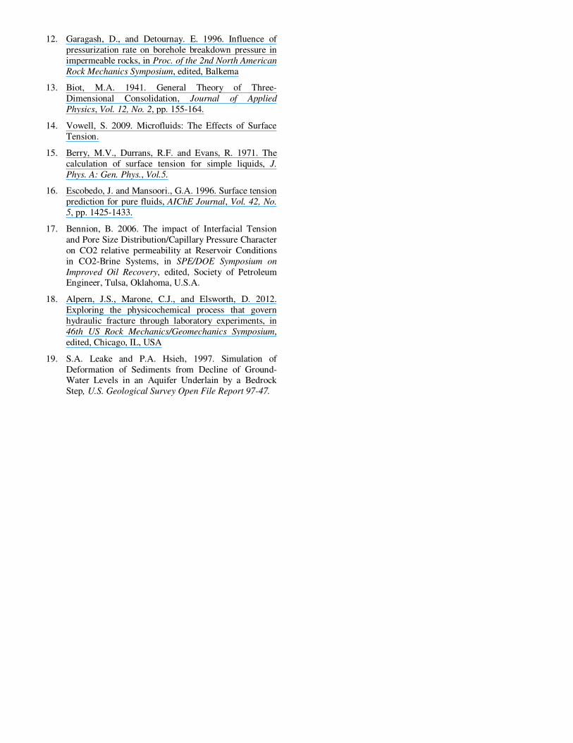
Fig. 12 3-D permeable and impermeable breakdown pressure
solutions validation
Fig. 12 shows the match of these experimental results
with the analytical data showing excellent agreement with the permeable solution. We conjecture that the
ability to drive fluid into the borehole wall is related to
the interfacial characteristics of the fluid. The inability of an invading supercritical fluid to sustain an interface
with a pre-existing fluid within the porous medium is
one such mechanism to promote the exclusion of fluids at sub-critical pressures and to allow penetration at
super-critical pressures (and temperatures).
5. CONCLUSIONS
We develop expressions based on Biot effective stress
theory to predict breakdown pressure for longitudinal and transverse fracture on finite length boreholes. We
use these relationships to explore the physical
dependencies of fracture breakdown pressures and show that an approximate factor of two exists in the
breakdown stress where fluids either invade or are
excluded from the borehole wall. We extend these relationships for finite length boreholes to replicate
experimental conditions. These solutions are used to
explain observations for different breakdown stresses where different pressurizing fluids are used in the
boreholes.
This is consistent with the observation that interfacial tension governs fluid invasion in matrix and therefore
influences the breakdown process. The negligible
interfacial tension in supercritical fluids allow easy invasion into the matrix, while the subcritical fluid with
larger interfacial tension requires a higher pressure to
invade and cause subsequent breakdown of the borehole. The injected fluid's infiltration ability which is decided
by the fluid state/properties could therefore affect the
fracture breakdown process.
ACKNOWLEDGEMENT
The authors would like to thank Chevron Energy Technology Company for the financial support and
permission to publish this paper.
REFERENCES
1. Kutter, H.K. 1970. Stress Analysis of a pressurized
circular hole with radial cracks in an infinite elastic
plate, Int. J. Fracture, 6:233-247.
2. Newman, J.C. 1971. An improved method of
collocation for the stress analysis of cracked plates with
various shaped boundaries, NASA TN, 1-45.
3. Tweed, J. and Rooke, D.P. 1973. The distribution of
stress near the tip of a radial crack at the edge of a
circular hole, Int. J. Engng. Sci., 11:1185-1195.
4. Hubbert, M.K., and Willis, D.G. 1957. Mechanics of
Hydraulic Fracturing, Trans. Am. Inst. Min. Eng., 210,
pp. 53-168.
5. Haimson, B., and Fairhurst, C. 1967. Initiation and
Extension of Hydraulic Fractures in Rocks, Soc. Pet.
Eng., 310-318.
6. Timoshenko, S.P. a. G., J.N. 1951. Theory of Elasticity,
McGraw Hill Publishing Co.
7. Zoback, M.D., Rummel, F., Jung, R. and Raleigh, C.B.
1977. Laboratory Hydraulic Fracturing Experiments in
Intact and Pre-fractured Rock, Int. J. Rock Mech. Min.
Sci. & Geomech. Abstr., Vol. 14, 49-58.
8. Solberg, P., Lockner, D. and Byerlee, J.D. 1980. Hydraulic Fracturing in Granite under Geothermal
Conditions, Int. J. Rock Mech. Min. Sci. & Geomech.
Abstr., Vol. 17, pp. 25-33.
9. Zhengwen Zeng, and. Roegiers., J.C. 2002.
Experimental Observation of Injection Rate Influence
on the Hydraulic Fracturing Behavior of a Tight Gas
Sandstone, in SPE/ISRM Rock Mechanics Conference,
edited, Society of Petroleum Engineers Inc., Irving, Texas
10. Wu, H., Golovin, E., Shulkin, Yu. and Chudnovsky, A.
2008. Observations of Hydraulic Fracture Initiation and
Propagation in a Brittle Polymer, in 42nd US Rock
Mechanics Symposium and 2nd U.S. - Canada Rock
Mechanics Symposium, edited, ARMA, American Rock
Mechanics Association, San Francisco.
11. Detornay, E. and Cheng. A. 1992. Influence of Pressurization Rate on the Magnitude of Breakdown
Pressure, Rock Mechanics, Tillerson & Wawersik (eds)
Balkeman Publishers, Rotterdam, The Netherlands,
325-333.
12. Garagash, D., and Detournay. E. 1996. Influence of
pressurization rate on borehole breakdown pressure in
impermeable rocks, in Proc. of the 2nd North American
Rock Mechanics Symposium, edited, Balkema
13. Biot, M.A. 1941. General Theory of Three-
Dimensional Consolidation, Journal of Applied
Physics, Vol. 12, No. 2, pp. 155-164.
14. Vowell, S. 2009. Microfluids: The Effects of Surface
Tension.
15. Berry, M.V., Durrans, R.F. and Evans, R. 1971. The
calculation of surface tension for simple liquids, J.
Phys. A: Gen. Phys., Vol.5.
16. Escobedo, J. and Mansoori., G.A. 1996. Surface tension
prediction for pure fluids, AIChE Journal, Vol. 42, No.
5, pp. 1425-1433.
17. Bennion, B. 2006. The impact of Interfacial Tension
and Pore Size Distribution/Capillary Pressure Character
on CO2 relative permeability at Reservoir Conditions
in CO2-Brine Systems, in SPE/DOE Symposium on
Improved Oil Recovery, edited, Society of Petroleum Engineer, Tulsa, Oklahoma, U.S.A.
18. Alpern, J.S., Marone, C.J., and Elsworth, D. 2012.
Exploring the physicochemical process that govern
hydraulic fracture through laboratory experiments, in
46th US Rock Mechanics/Geomechanics Symposium,
edited, Chicago, IL, USA
19. S.A. Leake and P.A. Hsieh, 1997. Simulation of
Deformation of Sediments from Decline of Ground-Water Levels in an Aquifer Underlain by a Bedrock
Step, U.S. Geological Survey Open File Report 97-47.