Pressure pulsation in roller pumps: A validated lumped parameter model
Upload
independentCategory
view
1download
0
International Journal of Thermal Sciences 47 (2008) 282–292www.elsevier.com/locate/ijts
On the validity of lumped capacitance approaches for the numericalprediction of heat and mass transfer in desiccant airflow systems
C.R. Ruivo 1, J.J. Costa ∗, A.R. Figueiredo
ADAI, Department of Mechanical Engineering, University of Coimbra, P 3030 788 Coimbra, Portugal
Received 28 October 2005; accepted 28 January 2007
Available online 3 April 2007
Abstract
In the present work, a detailed model of simultaneous heat and mass transfer through a desiccant micro-porous medium of a channel wallof compact heat and mass exchangers, such as desiccant wheels, was developed. The relevant phenomena considered by this model within theporous medium are surface diffusion of the adsorbed water, Knudsen diffusion of water vapour, heat conduction and the sorption process. A one-dimensional formulation of this model is used to investigate the validity of two simplifying approaches based on the lumped-capacitance method.One consists of neglecting the transversal heat and mass transfer resistances within the porous medium, the other of cancelling only the thermalresistance.
Results are presented for a wide range of values of the layer thickness of the porous medium. It is concluded that the hypothesis of null-resistances in the cross direction is valid only for layer thicknesses lower than 0.1 mm, approximately, while the approach based on the thermallumped capacitance model is valid for layer thicknesses lower than 5 mm. Finally, a dimensional analysis of interfacial balances leads to theconclusion that the Biot number for surface diffusion is several orders of magnitude higher than the corresponding thermal Biot number.© 2007 Elsevier Masson SAS. All rights reserved.
Keywords: Adsorption; Desiccant layer; Lumped capacitance models; Heat and mass exchangers
1. Introduction
The study of the transport phenomena in desiccant airflowsystems has been addressed in numerous research works, manyof them concerning combined desiccant cooling and dehumid-ification, air filtering, air dehumidification and energy recoveryprocesses (e.g., [1–16]).
A significant number of studies was carried out to predict thebehaviour of air dehumidifying systems using simplified math-ematical models (e.g., [17–27]). In most of them, the heat andmass transport phenomena occurring inside the porous desic-cant medium are not described in a very detailed way, simplifiedapproaches being adopted instead. Pseudo-gas-side controlled
* Corresponding author. Tel.: +351 239 790732; fax: +351 239 790771.E-mail addresses: [email protected] (C.R. Ruivo), [email protected]
(J.J. Costa).1 Present address: Área Departamental de Engenharia Mecânica, Escola Su-
perior de Tecnologia, Universidade do Algarve, Campus da Penha, 8005-139Faro, Portugal.
1290-0729/$ – see front matter © 2007 Elsevier Masson SAS. All rights reserved.doi:10.1016/j.ijthermalsci.2007.01.032
models have been the most used models (e.g., [21]) based onfictitious overall heat and mass transfer coefficients when it isimportant to take into account the internal resistances in thedesiccant. A single-blow test procedure for compact heat andmass transfer exchangers to evaluate those overall transfer co-efficients is presented in [28]. An alternative to this approachconsists in using the parabolic profile assumption, which valid-ity was investigated in [29] and supports the rotary desiccantdehumidifier model used in [23].
The range of validity of such models can be investigatedby using experimental techniques and by detailed numericalmodelling. The adsorbate surface diffusion inside microporousmedia like silica gel is known to be a dominant mechanism [6].Some studies concerning the use of correlations for solid-sidemass diffusivity estimation are important references [30–33],but large discrepancies between experimental and theoreticalvalues are observed [33].
The air stream behaviour and its interaction with the desic-cant medium are also often treated in a simplified way, namelyby assuming a fictitious bulk flow pattern, as well as fictitious
C.R. Ruivo et al. / International Journal of Thermal Sciences 47 (2008) 282–292 283
Nomenclature
Bih Biot number for heat transferBiK Biot number for Knudsen diffusionBim Biot number for mass transferBis Biot number for surface diffusionC� mass concentration of adsorbed water . . . . kg m−3
C+� dimensionless mass concentration of adsorbed wa-
terCv vapour mass concentration of the gas mixture
inside the porous medium . . . . . . . . . . . . . . . kg m−3
C+v dimensionless vapour mass concentration of the gas
mixture inside the porous mediumCv,f vapour mass concentration in the
airflow . . . . . . . . . . . . . . . . . . . . . . . . . . . . . . . . kg m−3
Cv,i vapour mass concentration in the gas mixture at theinterface . . . . . . . . . . . . . . . . . . . . . . . . . . . . . . kg m−3
cp,f specific heat of the air flow . . . . . . . . . J kg−1 ◦C−1
cp,p specific heat of porous medium . . . . . J kg−1 ◦C−1
cp,v specific heat of water vapour . . . . . . . . J kg−1 ◦C−1
Df diffusion coefficient of water vapour in theairflow . . . . . . . . . . . . . . . . . . . . . . . . . . . . . . . . m2 s−1
DK,eff effective coefficient of Knudsendiffusion . . . . . . . . . . . . . . . . . . . . . . . . . . . . . . . m2 s−1
Dp coefficient of water (mass) diffusion inside theporous medium. . . . . . . . . . . . . . . . . . . . . . . . . m2 s−1
Ds,eff effective coefficient of surface diffusion(of adsorbed water) . . . . . . . . . . . . . . . . . . . . . m2 s−1
dhyd hydraulic diameter . . . . . . . . . . . . . . . . . . . . . . . . . . mhads heat of adsorption . . . . . . . . . . . . . . . . . . . . . . . J kg−1
hh convection heat transfercoefficient . . . . . . . . . . . . . . . . . . . . . . . . W m−2 ◦C−1
hfg latent heat of vaporization . . . . . . . . . . . . . . . J kg−1
h� enthalpy of liquid water . . . . . . . . . . . . . . . . . J kg−1
h′� enthalpy of adsorbed water . . . . . . . . . . . . . . . J kg−1
hm convection mass transfer coefficient . . . . . . . m s−1
hv enthalpy of vapour . . . . . . . . . . . . . . . . . . . . . . J kg−1
h′w heat of wetting . . . . . . . . . . . . . . . . . . . . . . . . . . J kg−1
jads adsorption rate per unit area of theinterface . . . . . . . . . . . . . . . . . . . . . . . . . . . kg s−1 m−2
japp heat or mass convective flux predicted by the sim-plified model
jh convective heat flux . . . . . . . . . . . . . . . . . . . . W m−2
j+h dimensionless heat conduction flux
j+h,ads dimensionless heat generation/consumption rate per
unit area of the interfacej+
K dimensionless Knudsen flux at the interfacejm convective mass flux . . . . . . . . . . . . . . . . kg s−1 m−2
jref heat or mass convective flux predicted by the de-tailed model
j+s dimensionless surface diffusion flux at the interface
Le Lewis numberMv molecular mass of water . . . . . . . . . . . . . kg kmol−1
Nu Nusselt numberp pressure of the air–vapour mixture . . . . . . . . . . . . Papv partial pressure of water vapour . . . . . . . . . . . . . . Pa
pv,sat saturation pressure of water vapour . . . . . . . . . . . PaRgv particular gas constant of the air–vapour
mixture . . . . . . . . . . . . . . . . . . . . . . . . . . . J kg−1 ◦C−1
Rv particular gas constant of watervapour . . . . . . . . . . . . . . . . . . . . . . . . . . . . J kg−1 ◦C−1
rgv average radius of pore volume occupied by thegaseous phase . . . . . . . . . . . . . . . . . . . . . . . . . . . . . . m
Sads source-term in the energy conservationequation (3) . . . . . . . . . . . . . . . . . . . . . . . . . . . W m−3
Sh Sherwood numberSv-� source-term in the mass conservation equations (1)
and (2) . . . . . . . . . . . . . . . . . . . . . . . . . . . . kg s−1 m−3
s thickness of the desiccant layer . . . . . . . . . . . . . . . mT temperature . . . . . . . . . . . . . . . . . . . . . . . . . . . . . . . . ◦CT average temperature of the porous medium. . . . ◦CTi temperature of the interface . . . . . . . . . . . . . . . . . ◦CTf temperature of the airflow . . . . . . . . . . . . . . . . . . . ◦CT0 initial temperature in the porous medium . . . . . ◦Ct time coordinate . . . . . . . . . . . . . . . . . . . . . . . . . . . . . . st1 time to the variable X� predicted by the detailed
model attain 90% of the maximum variation . . . . swv water-vapour content of the gas mixture inside the
porous medium (d.b.) . . . . . . . . . . . . . . . . . . kg kg−1
wv average water-vapour content of the gas mixture inthe porous medium (d.b.) . . . . . . . . . . . . . . . kg kg−1
X� adsorbed water content (d.b.) . . . . . . . . . . . kg kg−1
X� average adsorbed water content in the porousmedium (d.b.) . . . . . . . . . . . . . . . . . . . . . . . . . kg kg−1
X�,0 initial adsorbed water content in the porousmedium . . . . . . . . . . . . . . . . . . . . . . . . . . . . . . kg kg−1
X+� dimensionless average adsorbed water content in
the porous mediumy spatial coordinate . . . . . . . . . . . . . . . . . . . . . . . . . . . m
Greek symbols
�ε deviation between the evolutions of the convectiveheat or mass fluxes, with respect to the detailedmodel (Eq. (19))
εgv volume fraction of the gaseous mixture within theporous medium
φ generic variable, i.e., temperature, adsorbed watercontent or water-vapour content
Φ+h,ads ratio between the heat released in the phase change
of the vapour flux convected to the interface, if thephase change were completely achieved, and theconvection heat flux (Eq. (26a))
ϕv vapour mass fraction of the gas mixture inside theporous medium . . . . . . . . . . . . . . . . . . . . . . . . kg kg−1
ϕv,eq vapour mass fraction of the gas mixture within theporous medium at equilibrium . . . . . . . . . . kg kg−1
ϕv,f vapour mass fraction in the airflow . . . . . . kg kg−1
ϕv,i vapour mass fraction of the gas mixture at theinterface . . . . . . . . . . . . . . . . . . . . . . . . . . . . . . kg kg−1
284 C.R. Ruivo et al. / International Journal of Thermal Sciences 47 (2008) 282–292
λf thermal conductivity of the airflow . . W m−1 ◦C−1
λp thermal conductivity of the porousmedium . . . . . . . . . . . . . . . . . . . . . . . . . . W m−1 ◦C−1
ρ∗d apparent density of the dry desiccant . . . . . kg m−3
ρf density of the airflow . . . . . . . . . . . . . . . . . . . kg m−3
ρgv density of the fluid inside the porousmedium . . . . . . . . . . . . . . . . . . . . . . . . . . . . . . . kg m−3
ρ∗gv apparent density of the gas mixture inside the
porous medium . . . . . . . . . . . . . . . . . . . . . . . . kg m−3
τ� tortuosity of the adsorbed water path within theporous medium
τgv tortuosity of the water vapour pathψ relative pressure, i.e., ratio of the partial vapour
pressure to the saturation vapour pressure
Superscripts
* apparent density′ adsorbed water
+ dimensionless variable
Subscripts
0 initial conditionads relative to the adsorption phenomenond dry desiccanteff effective quantityeq equilibrium conditionsf airflowgv gaseous mixture (air–vapour)h heati solid-airflow interfacem massp porous mediumsat saturation conditionst steady-state conditionv water vapour� free liquid water or adsorbed water
heat and mass convection coefficients for the gas side. Con-cerning convection heat transfer, work was carried out to obtainvalues of the Nusselt number in corrugated ducts of compactdesiccant matrixes by holographic interferometry [34] and bydetailed numerical modelling of the airflow field [35,36]. Theconvection mass transfer can be estimated through the Sher-wood number, this one being given by the analogy between heatand mass transfer characterized by Le ≈ 1.
The experimental work on desiccant devices such as des-iccant wheels has been focused on the validation of physicalprediction models [8,37–40], the development of simplifiedmodels based on experimental data correlations [40–42] and theperformance characterization by carrying out numerous exper-iments under various operating conditions [43,44].
Several studies of partial or complete solid desiccant systemsfor air conditioning have been conducted, mainly supported onexperimental results [45,46] or using mathematical modellingwith the behaviour of the desiccant device taken from properlaboratory experiments [47], manufacturer’s performance data[48] or specific modelling software [49–51].
When advanced numerical methods are used, solving thecomplete set of differential transport equations, a number ofcritical issues still remains, such as the lack of suitable func-tions to describe the variation of the porous medium proper-ties [8,42,52,53] and the complexity of numerically solving theintrinsically coupled phenomena within the porous desiccantsolid and the great time consumption of computational calcu-lations [23]. An additional delicate question consists of accu-rately representing the solid-fluid interface phenomena [11,15].Nevertheless, advanced mathematical models—including sur-face diffusion of the adsorbed phase, Knudsen diffusion of thegaseous phase, thermal diffusion and sorption as local processesin the porous desiccant layer—have been adopted to support nu-merical simulations of the behaviour of desiccant and enthalpywheels [53–56]. Some of the adopted assumptions [56] were:
(i) the channel wall was made of a composite material, whichis assumed to be an uniform mixture of substratum anddesiccant materials;
(ii) the mass fraction of desiccant in the porous medium wastaken as thrice the mass fraction of substratum;
(iii) the adsorption heat and the volume fraction of the gaseousphase inside the porous medium were both constant anduniform.
It is recognized the importance of validating the numericalresults by comparison with experimental data. The extensivebibliographic research referred above shows a lack of infor-mation for the complete characterization of the desiccant me-dia as required for the validation of detailed models. In somecases, the degree of accuracy of the measured results is notincluded and, in other works, a poor degree of accuracy is re-ported. A difference of about 10% was obtained in [9] betweennumerical and experimental results for the behaviour of a des-iccant granular bed, which is attributed to inaccuracies in themeasurements and in the adopted correlations. Moreover, theexperimental exhaustive research of [40] on the behaviour ofa desiccant wheel showed significant mass and energy imbal-ances between the regeneration and the process air streams.
In the present work, the numerical modelling of the physi-cal behaviour of a layer of a desiccant composite is addressed,considering the complete set of governing equations for the lo-cal adsorption, heat conduction and mass diffusion within theporous medium. The dependence of the thermodynamic prop-erties, of the diffusion coefficients and of the volume fractionof the gaseous phase on the local primary variables (tempera-ture, adsorbed water content and vapour content) is also con-sidered. It is also supposed that the desiccant layer belongs tothe channel wall of a compact exchanger, which is crossed bya moist air–vapour flow. The hypothesis of one-dimensionalityassumed in this study—a plane and short element of the desic-cant layer—is mainly intended to better identify the effects to
C.R. Ruivo et al. / International Journal of Thermal Sciences 47 (2008) 282–292 285
be analysed, namely the importance of neglecting the internaldiffusive resistances.
2. Mathematical modelling
2.1. Physical model and simplifications
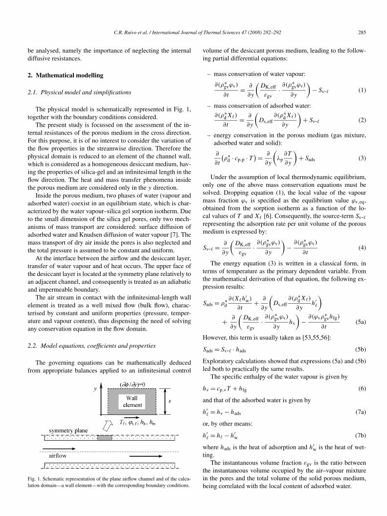
The physical model is schematically represented in Fig. 1,together with the boundary conditions considered.
The present study is focussed on the assessment of the in-ternal resistances of the porous medium in the cross direction.For this purpose, it is of no interest to consider the variation ofthe flow properties in the streamwise direction. Therefore thephysical domain is reduced to an element of the channel wall,which is considered as a homogeneous desiccant medium, hav-ing the properties of silica-gel and an infinitesimal length in theflow direction. The heat and mass transfer phenomena insidethe porous medium are considered only in the y direction.
Inside the porous medium, two phases of water (vapour andadsorbed water) coexist in an equilibrium state, which is char-acterized by the water vapour–silica gel sorption isotherm. Dueto the small dimension of the silica gel pores, only two mech-anisms of mass transport are considered: surface diffusion ofadsorbed water and Knudsen diffusion of water vapour [7]. Themass transport of dry air inside the pores is also neglected andthe total pressure is assumed to be constant and uniform.
At the interface between the airflow and the desiccant layer,transfer of water vapour and of heat occurs. The upper face ofthe desiccant layer is located at the symmetry plane relatively toan adjacent channel, and consequently is treated as an adiabaticand impermeable boundary.
The air stream in contact with the infinitesimal-length wallelement is treated as a well mixed flow (bulk flow), charac-terised by constant and uniform properties (pressure, temper-ature and vapour content), thus dispensing the need of solvingany conservation equation in the flow domain.
2.2. Model equations, coefficients and properties
The governing equations can be mathematically deducedfrom appropriate balances applied to an infinitesimal control
Fig. 1. Schematic representation of the plane airflow channel and of the calcu-lation domain—a wall element—with the corresponding boundary conditions.
volume of the desiccant porous medium, leading to the follow-ing partial differential equations:
– mass conservation of water vapour:
∂(ρ∗gvϕv)
∂t= ∂
∂y
(DK,eff
εgv· ∂(ρ∗
gvϕv)
∂y
)− Sv-� (1)
– mass conservation of adsorbed water:
∂(ρ∗dX�)
∂t= ∂
∂y
(Ds,eff
∂(ρ∗dX�)
∂y
)+ Sv-� (2)
– energy conservation in the porous medium (gas mixture,adsorbed water and solid):
∂
∂t
(ρ∗
d · cp,p · T ) = ∂
∂y
(λp
∂T
∂y
)+ Sads (3)
Under the assumption of local thermodynamic equilibrium,only one of the above mass conservation equations must besolved. Dropping equation (1), the local value of the vapourmass fraction ϕv is specified as the equilibrium value ϕv,eq,obtained from the sorption isotherm as a function of the lo-cal values of T and X� [6]. Consequently, the source-term Sv-�representing the adsorption rate per unit volume of the porousmedium is expressed by:
Sv-� = ∂
∂y
(DK,eff
εgv· ∂(ρ∗
gvϕv)
∂y
)− ∂(ρ∗
gvϕv)
∂t(4)
The energy equation (3) is written in a classical form, interms of temperature as the primary dependent variable. Fromthe mathematical derivation of that equation, the following ex-pression results:
Sads = ρ∗d∂(X�h
′w)
∂t+ ∂
∂y
(Ds,eff
∂(ρ∗dX�)
∂yh′
�
)+ ∂
∂y
(DK,eff
εgv· ∂(ρ∗
gvϕv)
∂yhv
)− ∂(ϕvρ
∗gvhfg)
∂t(5a)
However, this term is usually taken as [53,55,56]:
Sads = Sv-� · hads (5b)
Exploratory calculations showed that expressions (5a) and (5b)led both to practically the same results.
The specific enthalpy of the water vapour is given by
hv = cp,vT + hfg (6)
and that of the adsorbed water is given by
h′� = hv − hads (7a)
or, by other means:
h′� = h� − h′
w (7b)
where hads is the heat of adsorption and h′w is the heat of wet-
ting.The instantaneous volume fraction εgv is the ratio between
the instantaneous volume occupied by the air–vapour mixturein the pores and the total volume of the solid porous medium,being correlated with the local content of adsorbed water.
286 C.R. Ruivo et al. / International Journal of Thermal Sciences 47 (2008) 282–292
The effective diffusivity associated with Knudsen diffusionin a porous desiccant medium may be written as [6]:
DK,eff = 97rgv
√T + 273.15
Rv
εgv
τgv(8)
The effective diffusivity associated to the surface diffusionof adsorbed water Ds,eff in a porous desiccant medium is di-rectly influenced by the path tortuosity τ� and depends on thepair adsorbate–adsorbent. In the present work, the following ex-pression was used [6]:
Ds,eff = Ds0
τ�
· exp
( −4.5 × 10⁻⁴hads
bRv(T + 273.15)
)(9)
where b depends on the type of adsorption bond and Ds0 is aconstant that depends on the adsorbent.
The effective thermal conductivity of the porous medium λpis difficult to predict accurately due to the coupled transfer phe-nomena. An average value is used according to the conductivityand mass fraction of each component phase. A similar proce-dure is used regarding the specific heat of the porous medium.
Finally, for the graphical representation of the results, themoisture content of the air–vapour mixture wv (mass fraction ofvapour on dry basis) is calculated from the vapour mass fractionϕv through
wv = ϕv/(1 − ϕv) (10)
2.3. Boundary conditions
The upper and the two lateral faces of the wall elementare considered adiabatic, as well as impermeable to both wa-ter phases (cf. Fig. 1). According to the low-mass-transfer ratetheory [57], the mass and heat fluxes evaluated on the gas sideof the interface are
jm = hm · ρf(ϕv,f − ϕv,i) (11)
and
jh = hh(Tf − Ti) (12)
respectively, where ϕv,i and Ti are instantaneous values at theinterface and ϕv,f and Tf are instantaneous bulk flow values.The convection heat and mass transfer coefficients are takenfrom the values of the Nusselt and the Sherwood numbers forthe fully developed laminar regime of an internal channel flow,which are related by the well-known Chilton–Colburn analogy:
Sh = Nu · Le−1/3 (13)
the Lewis number being estimated from its definition:
Le = λf/(ρfcp,fDf) (14)
The convection coefficients are then obtained by the expres-sions:
hh = Nu · λf/dhyd (15)
and
hm = Sh · Df/dhyd (16)
In a real channel the convection coefficients depend on the flowregime, the channel geometry and on the distance from thechannel inlet. The interface fluxes calculated through Eqs. (11)and (12) are positive in the y direction, i.e., when entering thewall element (cf. Fig. 1).
At the interface with the airflow, the following surface bal-ances can be written:[−DK,eff
εgv· ∂(ρ∗
gvϕv)
∂y− Ds,eff
∂(ρ∗dX�)
∂y
]y=0+
= hm · ρf(ϕv,f − ϕv,i) (17)
and[−DK,eff
εgv· ∂(ρ∗
gvϕv)
∂yhv − Ds,eff
∂(ρ∗dX�)
∂yh′
� − λp∂T
∂y
]y=0+
= hh(Tf − Ti) + hm · ρf(ϕv,f − ϕv,i) · hv,i (18)
2.4. Numerical modelling
The detailed model described above will be hereafter takenas the reference or standard model. The partial differentialequations (1)–(3) are discretized using the finite volume method[58] and solved through the tri-diagonal matrix algorithm(TDMA). An iterative procedure is performed in each timestep, in order to handle the strong coupling between the govern-ing equations and the non-linearities implied by the changingproperties. With appropriate control parameters, the resultingnumerical model showed a rather stable and robust behaviouralong the calculation procedure.
The calculation domain is divided into control-volumes,forming a Cartesian and non-uniform grid, which is gradu-ally expanded from the solid-flow interface towards the adia-batic/impermeable upper surface. A very short distance fromthe first inner grid point to the interface is imposed (0.5–1 µm), thus ensuring an accurate numerical representationof the boundary conditions expressed by Eqs. (11) and (12).These boundary conditions are introduced via the correspond-ing source-terms in the discretization equations [58]. Sincethe present study is focused on the assessment of the cross-direction resistances of the porous medium, the model is as-sumed one-dimensional and only one column of nodes issolved.
The time discretization consists of a step-by-step evolu-tion, each time interval being automatically generated alongthe numerical simulation of the transient process. Basically, thesharper is the time evolution of the dependent variables, theshorter are the time steps imposed, and conversely. This gener-ation algorithm guarantees a suitable representation of the tran-sient evolutions, while minimizing the computing time neededto simulate a complete adsorption/desorption process until thesteady-state.
Two simplifying approaches based on the lumped-capaci-tance method are numerically investigated. One corresponds tothe theoretical analysis of the system neglecting the internal re-sistances to the heat and mass diffusion (approach A—“NullRes.”). This global lumped-capacitance approach is achievedby specifying great enough values to all diffusion coefficients
C.R. Ruivo et al. / International Journal of Thermal Sciences 47 (2008) 282–292 287
(DK,eff,Ds,eff, and λp). The other approach (B—“Null ThermalRes.”) corresponds to the thermal lumped-capacitance methodand it is implemented by specifying a great enough value to thethermal conductivity λp of the medium.
3. Results and discussion
The use of dimensional analysis in the present situation isdifficult, due to the strong variations of some parameters alongthe transient process and, on the other hand, to the complexityinherent to the coupled phenomena involved.
Starting from a given initial state, the response of the desic-cant wall to a step change of the airflow conditions is simulateduntil global equilibrium is achieved. Table 1 summarizes the in-put data for the calculations, namely the state of the airflow andthe initial conditions of the desiccant wall.
The value 2.45 was assigned to the Nusselt number corre-sponding to heat convection between a uniform temperaturewall and a fully-developed laminar flow inside a corrugatesinusoidal-type channel of a compact exchanger [25]. The chan-nel cross-section area was 4.5 mm2, with an internal perimeterof 10.6 mm and a hydraulic diameter of 1.69 mm, approxi-mately.
Runs were conducted covering a wide range of values of thelayer thickness (0.01 mm to 5 mm) in order to study the validityof neglecting internal thermal and mass resistances (approach A—“Null Res.”) and only the thermal resistance (approach B—“Null Thermal Res.”).
The fluid properties of the binary air–vapour mixture dependon the primary variables T and ϕv. Appropriate ϕv-weightedfunctions were developed that take into account the individualdry-air and water–vapour properties available from thermody-namic tables [59]. The properties of the desiccant medium arereferred to silica gel RD [6].
3.1. Tests for grid and time-step dependence
Exploratory calculations were made for the adsorption casereferred in Table 1 and a wall-thickness of 5 mm, in order toanalyse the dependence of the results on the space and timediscretization. It was concluded that no more that 10 nodes inthe y direction were needed to guarantee grid-independent so-lutions. All subsequent calculations were then performed witha single column of 10 control-volumes. On the other hand, withthe procedure described in Section 2.4, the transient solutionsshowed very little dependence on the size and variation of the
Table 1Airflow and initial conditions of the desiccant wall for both the adsorption anddesorption processes simulated
Adsorption Desorption
Tf (◦C) 30 100wv,f (kg kg−1) 0.01 0.01p (Pa) 101 325 101 325T0 (◦C) 100 30X�,0 (kg kg−1) 0.0126 0.2363
time-interval, provided that a sufficiently short period (0.5 s,typically) is taken for the first 2 or 3 time-steps.
3.2. Significance of the internal resistances
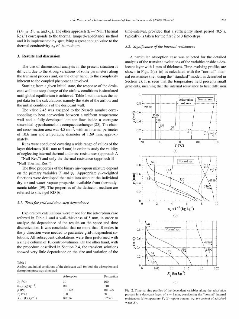
A particular adsorption case was selected for the detailedanalysis of the transient evolutions of the variables inside a des-iccant layer with 1 mm of thickness. Time-evolving profiles areshown in Figs. 2(a)–(c) as calculated with the “normal” inter-nal resistances (i.e., using the “standard” model, as described inSection 2). It is seen that the temperature field presents smallgradients, meaning that the internal resistance to heat diffusion
Fig. 2. Time-varying profiles of the dependent variables along the adsorptionprocess in a desiccant layer of s = 1 mm, considering the “normal” internalresistances: (a) temperature T ; (b) vapour content wv; (c) content of adsorbed
water X�.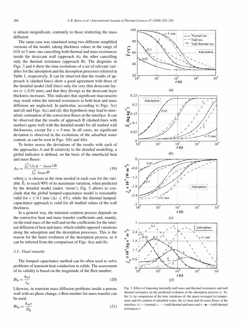
288 C.R. Ruivo et al. / International Journal of Thermal Sciences 47 (2008) 282–292
is almost insignificant, contrarily to those restricting the massdiffusion.
The same case was simulated using two different simplifiedversions of the model, taking thickness values in the range of0.01 to 5 mm: one cancelling both thermal and mass resistancesinside the desiccant wall (approach A), the other cancellingonly the thermal resistance (approach B). The diagrams inFigs. 3 and 4 show the time evolutions of a set of relevant vari-ables for the adsorption and the desorption processes referred inTable 1, respectively. It can be observed that the results of ap-proach A (dashed lines) show a good agreement with those ofthe detailed model (full lines) only for very thin desiccant lay-ers (s � 0.01 mm), and that they diverge as the desiccant layerthickness increases. This indicates that significant inaccuraciesmay result when the internal resistances to both heat and massdiffusion are neglected. In particular, according to Figs. 3(c)and (d) and Figs. 4(c) and (d), this hypothesis may lead to unre-alistic estimation of the convection fluxes at the interface. It canbe observed that the results of approach B (dashed-lines withmarker) agree well with the detailed model for all studied wallthicknesses, except for s = 5 mm. In all cases, no significantdeviation is observed in the evolutions of the adsorbed watercontent, as can be seen in Figs. 3(b) and 4(b).
To better assess the deviations of the results with each ofthe approaches A and B relatively to the detailed modelling, aglobal indicator is defined, on the basis of the interfacial heatand mass fluxes:
�ε =∫ t1
0 (jA,B − jnorm)dt∫ t10 jnorm dt
(19)
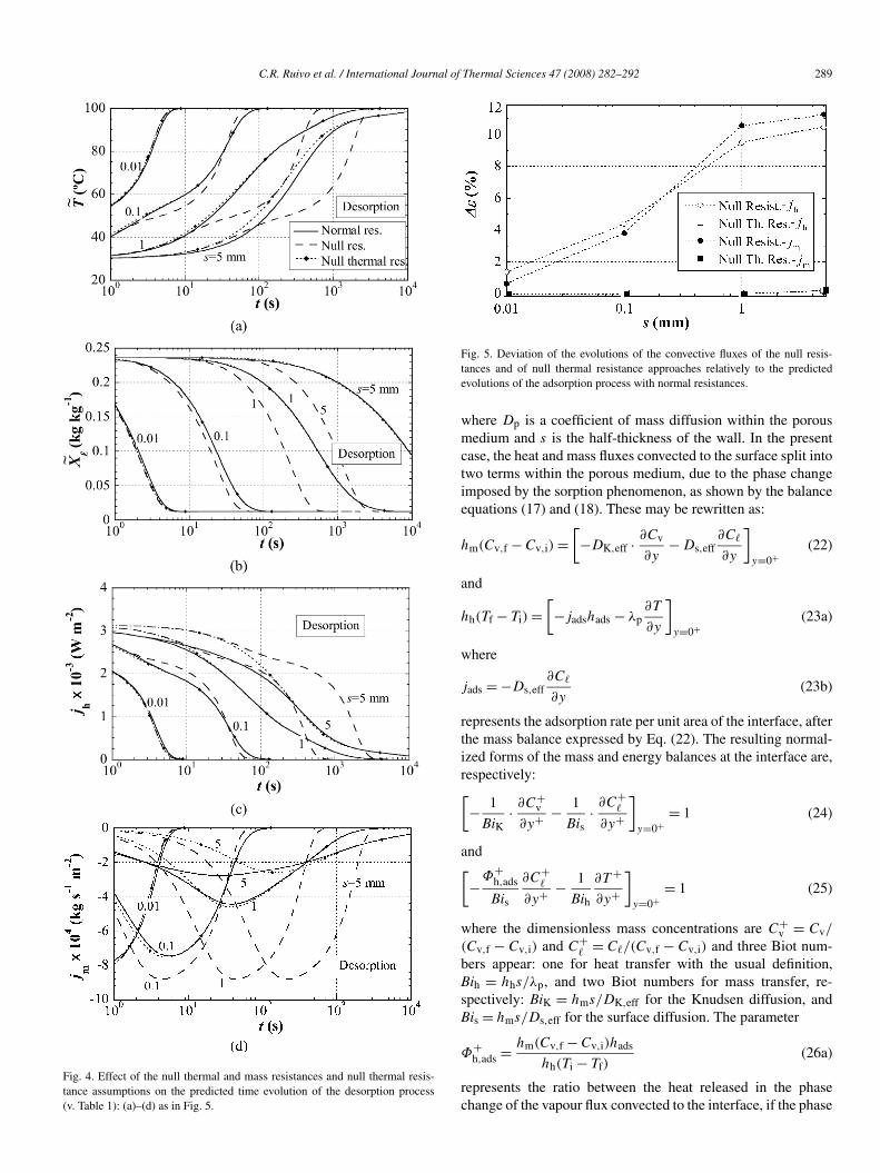
where t1 is chosen as the time needed in each case for the vari-able X� to reach 90% of its maximum variation, when predictedby the detailed model (index ‘norm’). Fig. 5 allows to con-clude that the global lumped-capacitance model is reasonablyvalid for s � 0.1 mm (�ε � 4%), while the thermal lumped-capacitance approach is valid for all studied values of the wallthickness.
In a general way, the transient sorption process depends onthe convective heat and mass transfer coefficients and, mainly,on the total mass of the wall and on the coefficients for the inter-nal diffusion of heat and mass, which exhibit opposed variationsalong the adsorption and the desorption processes. This is thereason for the faster evolution of the desorption process, as itcan be inferred from the comparison of Figs. 4(a) and (b).
3.3. Final remarks
The lumped capacitance method can be often used to solveproblems of transient heat conduction in solids. The assessmentof its validity is based on the magnitude of the Biot number:
Bih = hhs
λp(20)
Likewise, in transient mass diffusion problems inside a porouswall with no phase change, a Biot number for mass transfer canbe used:
Bim = hms
D(21)
p
Fig. 3. Effect of imposing internally null mass and thermal resistances and nullthermal resistance on the predicted evolution of the adsorption process (v. Ta-ble 1), by comparison of the time variations of: the space-averaged (a) temper-ature and (b) content of adsorbed water; the (c) heat and (d) mass fluxes at theinterface. ((—–) normal, (– – –) null thermal and mass and (—�—) null thermalresistances.)
C.R. Ruivo et al. / International Journal of Thermal Sciences 47 (2008) 282–292 289
Fig. 4. Effect of the null thermal and mass resistances and null thermal resis-tance assumptions on the predicted time evolution of the desorption process(v. Table 1): (a)–(d) as in Fig. 5.
Fig. 5. Deviation of the evolutions of the convective fluxes of the null resis-tances and of null thermal resistance approaches relatively to the predictedevolutions of the adsorption process with normal resistances.
where Dp is a coefficient of mass diffusion within the porousmedium and s is the half-thickness of the wall. In the presentcase, the heat and mass fluxes convected to the surface split intotwo terms within the porous medium, due to the phase changeimposed by the sorption phenomenon, as shown by the balanceequations (17) and (18). These may be rewritten as:
hm(Cv,f − Cv,i) =[−DK,eff · ∂Cv
∂y− Ds,eff
∂C�
∂y
]y=0+
(22)
and
hh(Tf − Ti) =[−jadshads − λp
∂T
∂y
]y=0+
(23a)
where
jads = −Ds,eff∂C�
∂y(23b)
represents the adsorption rate per unit area of the interface, afterthe mass balance expressed by Eq. (22). The resulting normal-ized forms of the mass and energy balances at the interface are,respectively:[− 1
BiK· ∂C+
v
∂y+ − 1
Bis· ∂C+
�
∂y+
]y=0+
= 1 (24)
and[−Φ+
h,ads
Bis
∂C+�
∂y+ − 1
Bih
∂T +
∂y+
]y=0+
= 1 (25)
where the dimensionless mass concentrations are C+v = Cv/
(Cv,f − Cv,i) and C+� = C�/(Cv,f − Cv,i) and three Biot num-
bers appear: one for heat transfer with the usual definition,Bih = hhs/λp, and two Biot numbers for mass transfer, re-spectively: BiK = hms/DK,eff for the Knudsen diffusion, andBis = hms/Ds,eff for the surface diffusion. The parameter
Φ+h,ads = hm(Cv,f − Cv,i)hads
hh(Ti − Tf)(26a)
represents the ratio between the heat released in the phasechange of the vapour flux convected to the interface, if the phase
290 C.R. Ruivo et al. / International Journal of Thermal Sciences 47 (2008) 282–292
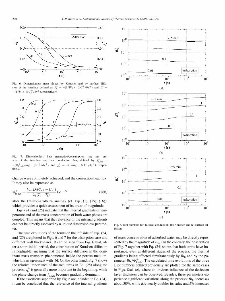
Fig. 6. Dimensionless mass fluxes by Knudsen and by surface diffu-sion at the interface defined as j+
K = −(1/BiK) · (∂C+v /∂y+) and j+
s =−(1/Bis) · (∂C+
�/∂y+), respectively.
Fig. 7. Dimensionless heat generation/consumption rate per unitarea of the interface and heat conduction flux, defined by j+
h,ads =−(Φ+
h,ads/Bis) · (∂C+�
/∂y+) and j+h = −(1/Bih) · (∂T +/∂y+), respec-
tively.
change were completely achieved, and the convection heat flux.It may also be expressed as:
Φ+h,ads = hadsDf(Cv,f − Cv,i)
λf(Ti − Tf)Le−1/3 (26b)
after the Chilton–Colburn analogy (cf. Eqs. (1), (15), (16)),which provides a quick assessment of its order of magnitude.
Eqs. (24) and (25) indicate that the internal gradients of tem-perature and of the mass concentration of both water phases arecoupled. This means that the relevance of the internal gradientscan not be directly assessed by a unique dimensionless parame-ter.
The time evolutions of the terms on the left side of Eqs. (24)and (25) are plotted in Figs. 6 and 7 for the adsorption case anddifferent wall thicknesses. It can be seen from Fig. 6 that, af-ter a short initial period, the contribution of Knudsen diffusionis negligible, meaning that the surface diffusion is the dom-inant mass transport phenomenon inside the porous medium,which is in agreement with [6]. On the other hand, Fig. 7 showsthe relative importance of the two terms in Eq. (25) along theprocess: j+
h is generally more important in the beginning, whilethe phase change term j+
h,ads becomes gradually dominant.If the assertions supported by Fig. 6 are included in Eq. (24),
it can be concluded that the relevance of the internal gradients
Fig. 8. Biot numbers for: (a) heat conduction, (b) Knudsen and (c) surface dif-fusion.
of mass concentration of adsorbed water may be directly repre-sented by the magnitude of Bis. On the contrary, the observationof Fig. 7 together with Eq. (24) shows that both terms have im-portance, even at different stages of the process, the thermalgradients being affected simultaneously by Bih and by the pa-rameter Bis/Φ
+h,ads. The calculated time evolutions of the three
Biot numbers defined previously are plotted for the same casesin Figs. 8(a)–(c), where an obvious influence of the desiccantlayer thickness can be observed. Besides, these parameters ex-perience significant variations along the process: Bih decreasesabout 30%, while BiK nearly doubles its value and BiS increases
C.R. Ruivo et al. / International Journal of Thermal Sciences 47 (2008) 282–292 291
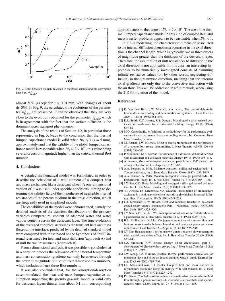
Fig. 9. Ratio between the heat released in the phase change and the convectionheat flux, Φ+
h,ads.
almost 50% (except for s � 0.01 mm, with changes of about±10%). In Fig. 9, the calculated time evolutions of the parame-ter Φ+
h,ads are presented. It can be observed that they are very
close to the evolutions obtained for the parameter j+h,ads, which
is in agreement with the fact that the surface diffusion is thedominant mass transport phenomenon.
The analysis of the results of Section 3.2, in particular thoserepresented in Fig. 5, leads to the conclusion that the thermallumped capacitance model is valid when Bih � 1 (s = 5 mm),approximately, and that the validity of the global lumped capac-itance model is reasonable when Bis � 2×10⁴, this value beingseveral orders of magnitude higher than the critical thermal Biotnumber.
4. Conclusions
A detailed mathematical model was formulated in order todescribe the behaviour of a wall element of a compact heatand mass exchanger, like a desiccant wheel. A one-dimensionalversion of it was used under specific conditions, aiming to de-termine the validity field of the hypotheses of negligible internalresistances of the porous medium in the cross direction, whichare frequently used in simplified models.
The capabilities of the model were demonstrated, namely thedetailed analysis of the transient distributions of the primaryvariables (temperature, content of adsorbed water and watervapour content) across the desiccant layer. The time evolutionsof the averaged variables, as well as the transient heat and massfluxes at the interface, predicted by the detailed standard modelwere compared with those based on the hypothesis of “null” in-ternal resistances for heat and mass diffusion (approach A) andof null thermal resistances (approach B).
From a dimensional analysis, it was possible to conclude thatin a sorption process the relevance of the internal temperatureand mass concentration gradients can only be assessed throughthe order of magnitude of a set of four dimensionless numbers,which includes at least three Biot numbers.
It was also concluded that, for the adsorption/desorptioncases simulated, the heat and mass lumped capacitance as-sumption supporting the pseudo gas-side model is valid onlyfor desiccant layers thinner than about 0.1 mm, corresponding
approximately to the range of Bis < 2×10⁴. The use of the ther-mal lumped capacitance model in this kind of coupled heat andmass transfer problems appears to be reasonable when Bih < 1.
In a 2-D modelling, the characteristic dimension associatedto the internal diffusion phenomena occurring in the axial direc-tion is the channel length, which is typically two or three ordersof magnitude greater than the thickness of the desiccant layer.Therefore, the assumption of null resistances to diffusion in theaxial direction is not applicable. In this case, an interesting hy-pothesis to be numerically investigated consists of assuminginfinite resistance values (or, by other words, neglecting dif-fusion) in the streamwise direction, meaning that the internalaxial gradients are only due to the convective interaction withthe air flow. This will be addressed in a future work, when usingthe 2-D formulation of the model.
References
[1] E. Van Den Bulk, J.W. Mitchell, S.A. Klein, The use of dehumidi-fiers in desiccant cooling and dehumidification systems, J. Heat TransferASME 108 (3) (1986) 684–692.
[2] R.R. Smith, C.C. Hwang, R.S. Dougall, Modeling of a solar-assisted des-iccant air conditioner for a residential building, Energy 19 (6) (1994)679–691.
[3] M.Ö. Çarpınlıoglu, M.Yıldırım, A methodology for the performance eval-uation of an experimental desiccant cooling system, Int. Commun. HeatMass Transfer, in press.
[4] J.J. Jurinak, J.W. Mitchell, Effect of matrix properties on the performanceof a counterflow rotary dehumidifier, J. Heat Transfer ASME 106 (4)(1984) 638–645.
[5] P. Majumdar, M.K. Sarwar, Performance of a desiccant dehumidifier bedwith mixed inert and desiccant materials, Energy 19 (1) (1994) 103–116.
[6] A. Pesaran, Moisture transport in silica gel particle beds, PhD thesis, Uni-versity of California, Los Angeles, USA, 1983.
[7] A.A. Pesaran, A. Mills, Moisture transport in silica gel packed beds—I.Theoretical study, Int. J. Heat Mass Transfer 30 (6) (1987) 1037–1049.
[8] A.A. Pesaran, A. Mills, Moisture transport in silica gel packed beds—II.Experimental study, Int. J. Heat Mass Transfer 30 (6) (1987) 1051–1060.
[9] J.Y. San, G.D. Jiang, Modeling and testing of a silica gel packed bed sys-tem, Int. J. Heat Mass Transfer 37 (8) (1994) 1173–1179.
[10] Y.I. Aristov, I.V. Mezentsev, V.A. Mukhin, Investigation of the moistureexchange in a stationary adsorbent layer through which air is passed, J. En-grg. Phys. Thermophys. 78 (2) (2005) 248–255.
[11] C.J. Simonson, R.W. Besant, Heat and moisture transfer in desiccantcoated rotary energy exchangers: Part I. Numerical model, HVAC&RRes. 3 (4) (1997) 325–350.
[12] J.Y. San, Y.C. Hsu, L.J. Wu, Adsorption of toluene on activated carbon ina packed bed, Int. J. Heat Mass Transfer 41 (21) (1998) 3229–3238.
[13] H.S. Al-Sharqawi, N. Lior, Conjugate computation of transient flow andheat and mass transfer between humid air and desiccant plates and chan-nels, Numer. Heat Transfer A—Appl. 46 (6) (2004) 525–548.
[14] J.Y. San, Heat and mass transfer in a two-dimension cross-flow regeneratorwith a solid conduction effect, Int. J. Heat Mass Transfer 36 (3) (1993)633–643.
[15] C.J. Simonson, R.W. Besant, Energy wheel effectiveness: part I—development of dimensionless groups, Int. J. Heat Mass Transfer 42 (12)(1999) 2161–2170.
[16] J.W. Jeong, S.A. Mumma, Practical thermal performance correlations formolecular sieve and silica gel loaded enthalpy wheels, Appl. Thermal En-grg. 25 (5–6) (2005) 719–740.
[17] I.L. Maclaine-Cross, P.J. Banks, Coupled heat and mass transfer inregenerators-prediction using an analogy with heat transfer, Int. J. HeatMass Transfer 15 (6) (1972) 1225–1242.
[18] P.J. Banks, Coupled equilibrium heat and single adsorbate transfer in fluidflow through a porous medium—I. Characteristic potentials and specificcapacity ratios, Chem. Engrg. Sci. 27 (5) (1972) 1143–1155.
292 C.R. Ruivo et al. / International Journal of Thermal Sciences 47 (2008) 282–292
[19] E. Van Den Bulk, J.W. Mitchell, S.A. Klein, Design theory for rotary heatand mass exchangers—I. Wave analysis of rotary heat and mass exchang-ers with infinite transfer coefficients, Int. J. Heat Mass Transfer 28 (8)(1985) 1575–1586.
[20] E. Van Den Bulk, J.W. Mitchell, S.A. Klein, Design theory for rotaryheat and mass exchangers—II. Effectiveness—number-of-transfer-unitsmethod for rotary heat and mass exchangers, Int. J. Heat Mass Trans-fer 28 (8) (1985) 1587–1595.
[21] W. Zheng, W.M. Worek, Numerical simulation of combined heat and masstransfer processes in a rotary dehumidifier, Numer. Heat Transfer A—Appl. 23 (2) (1993) 211–232.
[22] J.Y. San, S.C. Hsiau, Effect of axial solid heat conduction and mass diffu-sion in a rotary heat and mass regenerator, Int. J. Heat Mass Transfer 36 (8)(1993) 2051–2059.
[23] C.C. Ni, J.Y. San, Mass diffusion in a spherical microporous particle withthermal effect and gas-side mass transfer resistance, Int. J. Heat MassTransfer 43 (12) (2000) 2129–2139.
[24] Y.J. Dai, R.Z. Wang, H.F. Zhang, Parameter analysis to improve rotarydesiccant dehumidification using a mathematical model, Int. J. ThermalSci. 40 (4) (2001) 400–408.
[25] X.J. Zhang, Y.J. Dai, R.Z. Wang, A simulation study of heat and masstransfer in a honeycomb rotary desiccant dehumidifier, Appl. Thermal En-grg. 23 (8) (2003) 989–1003.
[26] M.N. Golubovic, W.M. Worek, Influence of elevated pressure on sorptionin desiccant wheels, Numer. Heat Transfer A—Appl. 45 (9) (2004) 869–886.
[27] Z. Gao, V.C. Mei, J.J. Tomlinson, Theoretical analysis of dehumidificationprocess in a desiccant wheel, Heat Mass Transfer 41 (11) (2005) 1033–1042.
[28] E. Van den Bulk, S.A. Klein, A single-blow test procedure for compactheat and mass exchangers, J. Heat Transfer ASME 112 (2) (1990) 317–322.
[29] D.D. Do, R.G. Rice, Validity of the parabolic profile assumption in ad-sorption, AIChE J. 32 (1) (1986) 149–154.
[30] E.R. Gilliland, R.F. Baddour, G.P. Perkinson, K.J. Sladek, Diffusion onsurfaces. I. Effect of concentration on the diffusivity of physically ad-sorbed gases, Indust. Engrg. Chem. Fundam. 13 (2) (1974) 95–99.
[31] K.J. Sladek, E.R. Gilliland, R.F. Baddour, Diffusion on surfaces. II. Cor-relation of diffusivities of physically and chemically adsorbed species,Indust. Engrg. Chem. Fundam. 13 (2) (1974) 100–105.
[32] C.C. Ni, J.Y. San, Measurement of apparent solid-side mass diffusivity ofa water vapour–silica gel system, Int. J. Heat Mass Transfer 45 (9) (2002)1839–1847.
[33] J.Y. San, C.C. Ni, S.H. Hsu, Validity of solid-side mass diffusivity in sim-ulation of water adsorbed by silica gel in packed beds, Int. J. ThermalSci. 41 (1) (2002) 41–49.
[34] R. Tauscher, U. Dinglreiter, B. Durst, F. Mayinger, Transport processes innarrow channels with application to rotary exchangers, Heat Mass Trans-fer 35 (2) (1999) 123–131.
[35] J.L. Niu, L.Z. Zhang, Heat transfer and friction coefficients in corrugatedducts confined by sinusoidal and arc curves, Int. J. Heat Mass Trans-fer 45 (3) (2002) 571–578.
[36] L.Z. Zhang, J.L. Niu, A numerical study of laminar forced convection insinusoidal ducts with arc lower boundaries under uniform wall tempera-ture, Numer. Heat Transfer A—Appl. 40 (1) (2001) 55–72.
[37] Y.K. Chuah, P. Norton, F. Kreith, Transient mass transfer in parallel pas-sage dehumidifiers with and without solid side resistance, J. Heat TransferASME 111 (4) (1989) 1038–1044.
[38] T. Kravchik, E. Korin, I. Borde, Influence of material properties and heatremoval on mass and heat transfer in a solid desiccant dehumidifier, Chem.Engrg. Process. 27 (1) (1990) 19–25.
[39] E. Van den Bulck, Transient heat and mass transfer in laminar flow forcedconvection in ducts, Int. J. Heat Mass Transfer 34 (4/5) (1991) 1249–1258.
[40] J.M. Cejudo, R. Moreno, A. Carrillo, Physical and neural network modelsof a silica-gel desiccant wheel, Energy Build. 34 (8) (2002) 837–844.
[41] A. Kodama, T. Hirayama, M. Goto, T. Hirose, R.E. Critoph, The use ofpsychrometric charts for the optimisation of a thermal swing desiccantwheel, Appl. Thermal Engrg. 21 (16) (2001) 1657–1674.
[42] M. Beccali, F. Butera, R. Guanella, R.S. Adhikari, Simplified models forthe performance evaluation of desiccant wheel dehumidification, Int. J.Energy Res. 27 (1) (2003) 17–29.
[43] S. Murali Krishna, S. Srinivasa Murthy, Experiments on silica gel rotarydehumidifier, Heat Recovery Systems & CHP 9 (5) (1989) 467–473.
[44] A. Kodama, M. Goto, T. Hirose, T. Kuma, Experimental study of opti-mal operation for a honeycomb adsorber operated with thermal swing,J. Chem. Engrg. Jpn. 26 (5) (1993) 530–535.
[45] E.A. Vineyard, J.R. Sand, D.J. Durfee, Parametric analysis of vari-ables that affect the performance of a desiccant dehumidification system,ASHRAE Trans. 106 (1) (2000).
[46] M.Ö. Çarpınlıoglu, M. Yıldırım, M. Kanoglu, Experimental study on anopen cycle desiccant cooling system, Int. J. Exergy 1 (2) (2004) 268–288.
[47] A. Kodama, W. Jin, M. Goto, T. Hirose, M. Pons, Entropic analysis ofadsorption open cycles for air conditioning. Part 2: interpretation of ex-perimental data, Int. J. Energy Res. 24 (3) (2000) 263–278.
[48] J.R. Camargo, C.D. Ebinuma, J.L. Silveira, Thermoeconomic analysis ofan evaporative desiccant air conditioning system. Part 2: interpretation ofexperimental data, Appl. Thermal Engrg. 23 (12) (2003) 1537–1549.
[49] M. Czachorski, J. Wurm, W.M. Worek, J. Mierke, P. Brillhart, Dynamictesting of desiccant matrices and computerized evaluation of performancemaps, ASHRAE Trans. 103 (Part 1) (1997) 833–840.
[50] P. Mazzei, F. Minichiello, D. Palma, Desiccant HVAC systems for com-mercial buildings, Appl. Thermal Engrg. 22 (5) (2002) 545–560.
[51] C.B. Beggs, S. Halliday, A theoretical evaluation of solar-powered desic-cant cooling in the United, Build. Serv. Engrg. Res. Technol. 20 (3) (1999)113–117.
[52] H.I. Henderson, J.R. Sand, An hourly building simulation tool to evaluatehybrid desiccant system configuration options, ASHRAE Trans. 109 (2)(2003) 551–564.
[53] L.A. Sphaier, W.M. Worek, Analysis of heat and mass transfer in poroussorbents used in rotary regenerators, Int. J. Heat Mass Transfer 47 (14–16)(2004) 3415–3430.
[54] P. Majumdar, Heat and mass transfer in composite pore structures for de-humidification, Sol. Energy 62 (1) (1998) 1–10.
[55] J.L. Niu, L.Z. Zhang, Effects of wall thickness on the heat and moisturetransfer in desiccant wheels for air dehumidification and enthalpy recov-ery, Int. Commun. Heat Mass Transfer 29 (2) (2002) 255–268.
[56] L.Z. Zhang, J.L. Niu, A pre-cooling Munters environmental control des-iccant cooling cycle in combination with chilled-ceiling panels, En-ergy 28 (3) (2003) 275–292.
[57] A.F. Mills, Heat and Mass Transfer, Irwin, 1995.[58] S.V. Patankar, Numerical Heat Transfer and Fluid Flow, Hemisphere,
McGraw-Hill, Washington, DC, 1980.[59] Y. Çengel, Heat Transfer—A Practical Approach, McGraw-Hill, New
York, 1998.
Copyright © 2022 FDOKUMEN