Nissan Cefiro Wiring Ecu Airflow - baixardoc
10
1 WIRING DIAGRAM BY MODEL This document describes car models to which the AFC neo (Product code: 401-A917) is applicable, and ECU terminal arrangement drawings. For the operating method and precautions for the AFC neo, refer to the Instruction Manual. When installing the AFC neo, both this document and the Instruction Manual are required. Even if the car model and manufacturing year coincide with the contents described in this document, this product may not be installed in certain specification vehicles or remodeled vehicles. The manufacturing years of applicable vehicles are as of May, 2008. For the latest vehicles applications, Please contact your local Apex Office or dealer for more information.
-
Upload
khangminh22 -
Category
Documents
-
view
0 -
download
0
Transcript of Nissan Cefiro Wiring Ecu Airflow - baixardoc

1
WIRING DIAGRAM BY MODEL
This document describes car models to which the AFC neo (Product code: 401-A917) is applicable, and ECU terminal arrangement drawings. For the operating method and precautions for the AFC neo, refer to the Instruction Manual. When installing the AFC neo, both this document and the Instruction Manual are required. Even if the car model and manufacturing year coincide with the contents described in this document, this product may not be installed in certain specification vehicles or remodeled vehicles. The manufacturing years of applicable vehicles are as of May, 2008. For the latest vehicles applications, Please contact your local Apex Office or dealer for more information.

2
!
!
Safety Precautions Safety messages and their meanings ________________________________ 3 WARNING __________________________________________________ 3 CAUTION __________________________________________________ 4 REQUEST___________________________________________________ 4 Installation Connection _______________________________________________________ 5 Connection diagram _______________________________________________ 6 ECU layout _______________________________________________________ 8 Viewing ECU pin layout ____________________________________________ 9 TOYOTA Table of Applicable Models......................................................................... 10 ECU Terminal Arrangement Table.............................................................. 18 NISSAN Table of Applicable Models......................................................................... 23 ECU Terminal Arrangement Table ............................................................. 28 HONDA Table of Applicable Models......................................................................... 31 ECU Terminal Arrangement Table.............................................................. 36 MITSUBISHI Table of Applicable Models......................................................................... 41 ECU Terminal Arrangement Table.............................................................. 43 MAZDA Table of Applicable Models......................................................................... 44 ECU Terminal Arrangement Table.............................................................. 46 SUBARU Table of Applicable Models......................................................................... 48 ECU Terminal Arrangement Table.............................................................. 50 SUZUKI Table of Applicable Models......................................................................... 52 ECU Terminal Arrangement Table.............................................................. 54 DAIHATSU Table of Applicable Models......................................................................... 56 ECU Terminal Arrangement Table.............................................................. 57
Contents

3
Safety Precaut ions Please read "Safety Precautions" carefully to operate the product with safety.
WARNING ! This indicates the existence of potential hazard that may result in death or serious injury of the operator or third persons if the product is wrongly operated in disregard of this indication.
Safety messages and their meanings
CAUTION ! This indicates the existence of potential hazard that may result in injury to the operator or third persons, and that will result in only physical damage if the product is wrongly operated in disregard of this indication.
REQUEST
WARNING ! □ Be sure to remove the negative terminal of the battery before working on wiring Do not work on wiring with the battery connected. This may cause a fire, electric shock, or other failures. In this case, we shall disclaim all responsibility for any damage or loss to the customer and third persons. □ Do not use this product for any application other than applicable vehicles or applicable goods. We will not guarantee any operation in vehicles other than indicated in this manual. Such an operation may cause an accident, fire or other failures. □ Do not install this product in an unstable place that may interfere with driving This may interfere with driving, resulting in a traffic accident. □ Do not tamper, disassemble, or modify this product.
This may cause an accident, fire, electric shock, or damage.
This indicates the contents of a failure in obtaining the full performance of the product or a product failure or faulty function item if the product is wrongly operated in disregard of this indication.
Safety Precautions

4
CAUTION ! □ Do not use an Electro-Tap
This may cause a malfunction or failure. Be sure to secure a connection with the accessory plug and splicer. □ Insulate connections and unused harnesses
If a connection or unused harness touches your body, a fire, electric shock, or other failures may occur. □ Do not run a harness around hot, humid, and movable areas of a vehicle
This may cause a malfunction, fire, or other failures. □ If you feel that the product is abnormal, stop operating it immediately
If this product gives out smoke or offensive smell, stop operating the product immediately and notify the office that is indicated on the back cover of this manual.
REQUEST Regarding the installation of this product, be sure that it is installed by an experienced professional. After the product is installed, hand this manual, instruction manual, and warranty to the customer (user). To remove the connector, hold it without pulling on its harness. Also use the connector without exposing its harness to excessive force. This product may cause noise interference with radio, TV, etc. depending on the mounting location and the routing of the signal harness.

5
□ Connecting the plug
Installat ion
Before installing this product, be sure to remove the negative terminal of the battery.
Connection
□ Insulating a splice
1, Peel off the coating of
the wires about 5 [mm] 2, Cover with a sleeve
3, Fold the wires 4, Caulk securely
Caulk the coating by these portions
Caulk the conductors by these portions
Make the caulking thrust into the wire
5, be sure to cover the connection with electrical tape
1, Remove 5 [mm] of the wire cover from the connecting wire
2, Strip 10 [mm] from the other connection wire
3, Wrap the two wires together
4, Securely fasten together other connection wire
Make the caulking thrust into the wire
Please move the sleeve to the caulked position when finished the caulking.
6
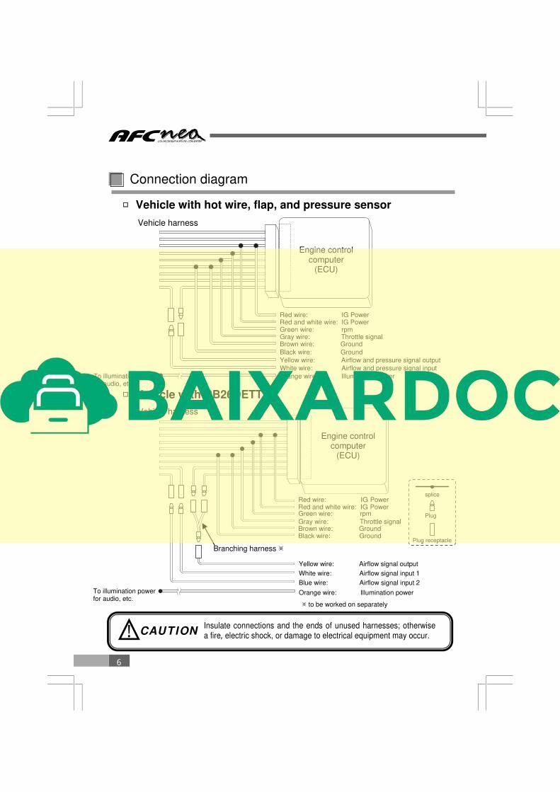
□ Vehicle with hot wire, flap, and pressure sensor
Connection diagram
Vehicle harness
Red wire: IG Power
Green wire: rpm Red and white wire: IG Power
Gray wire: Throttle signal Brown wire: Ground Black wire: Ground Yellow wire: Airflow and pressure signal output White wire: Airflow and pressure signal input
Engine control computer
(ECU)
Vehicle harness
Yellow wire: Airflow signal output White wire: Airflow signal input 1 Blue wire: Airflow signal input 2
Branching harness ※
□ Vehicle with RB26DETT
Orange wire: Illumination power
Orange wire: Illumination power
CAUTION !
To illumination power for audio, etc.
To illumination power for audio, etc.
splice
Plug
Plug receptacle
Engine control computer
(ECU)
Insulate connections and the ends of unused harnesses; otherwise a fire, electric shock, or damage to electrical equipment may occur.
※ to be worked on separately
Red wire: IG Power
Green wire: rpm Red and white wire: IG Power
Gray wire: Throttle signal Brown wire: Ground Black wire: Ground

7
□ Vehicle with Karman sensor
Connection diagram
□ Vehicle with VTEC
Vehicle harness
Vehicle harness
※②Some vehicles do not have VTM signals. To illumination power for audio, etc.
Engine control computer
(ECU)
Engine control computer
(ECU)
CAUTION ! Insulate connections and the ends of unused harnesses; otherwise a fire, electric shock, or damage to electrical equipment may occur.
Brown and white wire: Karman signal output Black and white wire: Karman signal input Orange wire: Illumination power To illumination power
for audio, etc.
Yellow wire: Airflow and pressure signal output White wire: Airflow and pressure signal input
Pink wire: VTEC signal output
Orange wire: Illumination power
Light green wire: VTM signal (※ ②) Purple wire: VTEC signal input
splice
Plug
Plug receptacle
Red wire: IG Power
Green wire: rpm Red and white wire: IG Power
Gray wire: Throttle signal Brown wire: Ground Black wire: Groundi
Red wire: IG Power
Green wire: rpm Red and white wire: IG Power
Gray wire: Throttle signal Brown wire: Ground Black wire: Ground
※ ①
※ ①Unconnection, Insulate

8
A
B C
D
E F
G
H I
J K
P L
M N
O
□ For details on working on the ECU, see symbols in the location column of
the applicable vehicle list from page 10.
ECU layout
A : Lower part of the passenger seat dash side B : Right side of the glove box C : Foot position of the passenger seat D : Inner part of the glove box E : Inner part of the center console F : Under the driver’s seat G : Under the passenger seat H : Near the steering column I : Left side of the meter panel J : Lower part of the driver’s seat dash side K : Left side of the center console L : Engine room M : Before the rear trunk N : Behind the driver’s seat O : Behind the passenger seat P : Upper inner part of the center console
9
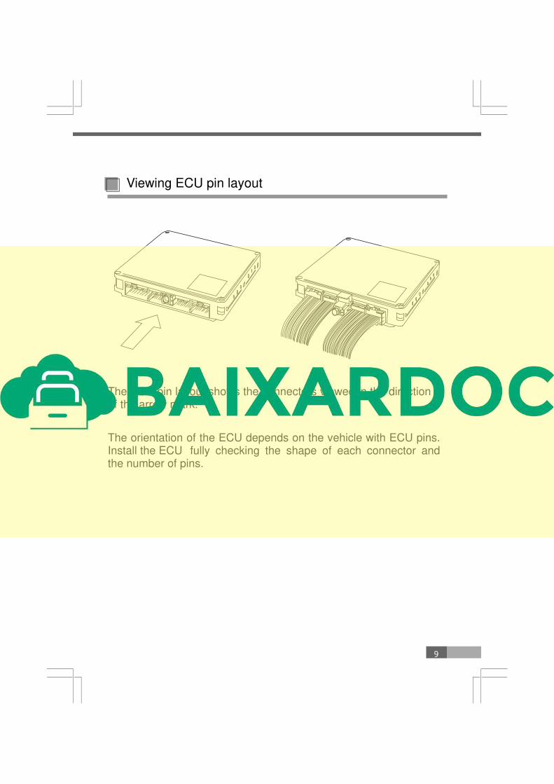
The ECU pin layout shows the connectors viewed in the direction of the arrow mark.
The orientation of the ECU depends on the vehicle with ECU pins. Install the ECU fully checking the shape of each connector and the number of pins.
Viewing ECU pin layout

10
HW- HotWire FL- Flap PR- Pressure KR- Karman
Table of Applicable Models ( TOYOTA)
Car Name Car Model Engine Model
Manufacturing year ECU Position
Terminal Drawing
Sensor Type
Remarks
CELSIOR
UCF2#
1UZ- FE
’97.7~‘00.7 L T10- e HW- 13
‘94.10~‘97.6
D T8- a
HW- 12
UCF1# ‘92.9~‘94.9
KR ‘89.10~‘92.8 T5- e
CROWN ROYAL JZS173 1JZ- GE ‘99.9~‘01.7 L T10- a PR- 16
CROWN ATHLETE
JZS171 1JZ- GTE ‘99.9~‘01.7 L
T10- b HW- 23
JZS173 1JZ- GE T10- a PR- 16
CROWN MAJESTA
UZS141 1UZ- FE ‘91.10~‘95.7 D T7- a KR
CROWN ESTATE
JZS171W 1JZ- GTE ‘99.9~‘01.7 L
T10- b HW- 23
JZS173W 1JZ- GE T10- a PR- 16
CROWN JZS14# 2JZ- GE ‘91.10~‘95.7 D T8- b PR- 3
ARISTO
JZS161 2JZ- GTE ‘97.8~‘04.11 L T10- c HW- 13
JZS160 2JZ- GE ‘97.8~‘00.6
JZS147 2JZ- GTE
‘91.10~‘97.7 C
T7- b PR- 1
2JZ- GE PR- 3
UZS143 1UZ- FE ‘92.10~‘97.7 T7- a KR
SOARER
UZZ40 3UZ- FE ‘01.4~‘05.7 L T11- b HW- 25
JZZ30 1JZ- GTE ‘96.8~‘01.3
C
T8- c HW- 12
‘91.5~‘96.7 PR- 1
JZZ31 2JZ- GE ‘94.1~‘96.7 PR- 3
UZZ31 1UZ- FE ‘94.1~‘95.4 T8- a
KR ‘91.5~‘93.12 T7- a
MZ20 7M- GTE ‘88.1~‘91.4
D
T5- a
‘86.1~‘87.12 T2- b
GZ20 1G- GTE ‘88.1~‘91.4 T5- a
FL- 1 ‘86.1~‘87.12 T2- d
T8- b
Explanation of sensor type indication Example PR-3
Sensor type Sensor number