
airflow through - AIVC
31
AIRFLOW THROUGH LARGE OPENINGS F. Allard* and Y. Utsumi# • Centre de Thermique, INSA de Lyon, Bat 307 F-69621 Cedex Villeurbanne (France) #Department of Architecture, Miyagi National College of Technology, Natori (Japan ),981-12 Summary The subject of airflow through large openings includes a large number of different problems, ranging from steady gravitational flows to fluctuating flows due to wind and including recirculating flows caused by boundary layer effects in a thermally d '. riven cavity. After a review describing the various physical phenomena, and the existing solu- tions available in the literature to solve this problem, we present in this paper a general solution to predict the behavior of large vertical openings. Tliis solution is able to take into account effects of density gradients and turbulence on gravita- tionnal flows, and is compatible with a. pressure network description for multizone modeling of airflow in buildings.
-
Upload
khangminh22 -
Category
Documents
-
view
1 -
download
0
Transcript of airflow through - AIVC
AIRFLOW THROUGH
LARGE OPENINGS
F. Allard* and Y. Utsumi#
• Centre de Thermique, INSA de Lyon, Bat 307
F-69621 Cedex Villeurbanne (France)
#Department of Architecture, Miyagi National
College of Technology, Natori (Japan ),981-12
Summary The subject of airflow through large openings includes a large number of different problems, ranging from steady gravitational flows to fluctuating flows due to wind t~rbulence, and including recirculating flows caused by boundary layer effects in a thermally d'.riven cavity.
After a review describing the various physical phenomena, and the existing solutions available in the literature to solve this problem, we present in this paper a general solution to predict the behavior of large vertical openings. Tliis solution is able to take into account effects of density gradients and turbulence on gravitationnal flows, and is compatible with a. pressure network description for multizone modeling of airflow in buildings.
CONTENTS
,.
. . 1. Introduction
. 2. Short Review of Literature
.!1 ,r
2.1 Gravitational flows through Vertical Openings
2.1.1 The Basic Problem
2.1.2 Coupling with a supply of air in one zone
., '- •
"l •
·.
2.1.3 Coupling with -vertical thermal gradients in ~a~}> zon~ 1.'. ~ 2.1.4 The Discharge Coefficient
2.2 Natural Convection Approach ''::! ,·,.
' , 1 ....
11 ~ \i ,t ' . .-,
2.3 Transient Flows and Turbulence Effects Through Vertica.l~Openings ~ ' '
2.3.1 Transient Flows . IJ;.
2.3.2 Unsteady Flows and Effects of Turbulence
2.4 Horizontal Opei:iings ., . '
3. Integrating Large Openings In a Multizone Air Flow Model
3.1 Existing Solutions
3.2 COl\flS Contribution
3.2.1 General numerical solution or the problem
3.2.2 Analytical solution of the problem without density gradients
3.2.3 Examples of solutions
3.2.3.l Influence of the turbulence effect
3.2.3.2 Influence or density gradients
4. Conclusion
-2-
\ .
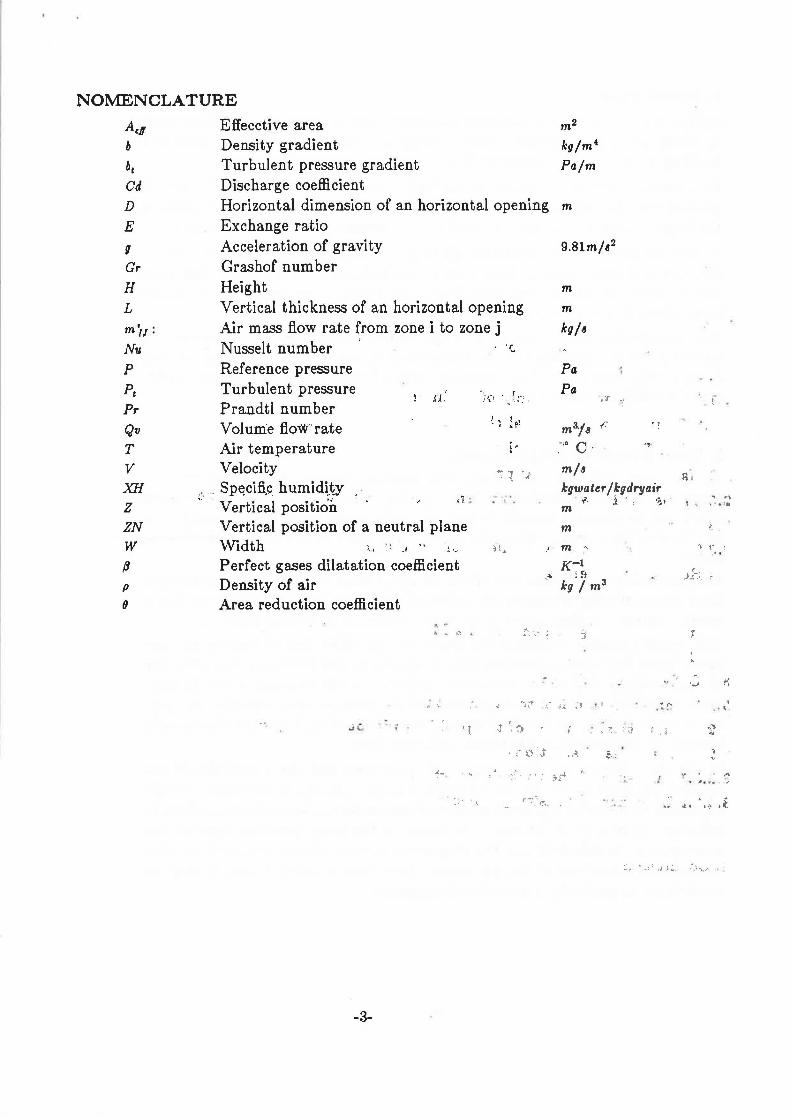
N01\1ENCLATURE A.11 Effecctive area m2
b Density gradient kg/m 4
be Turbulent pressure gradient Pa/m Cd Discharge coefficient D Horizontal dimension of an horizontal opening m
E Exchange ratio g Acceleration of gravity 9.8lm/a2
Gr Grashof number H Height m
L Vertical thickness of an horizontal opening m
m ii : Air mass flow rate from zone i to zone j kg/ B
Nu Nusselt number t
Reference pressure Turbulent pressure Prandtl number Vol um:e flow-· rate Air temperature Velocity
J_) .! f.
l'
Pa Pa
m3/a f'
.''0 c. m/a
.,
p
Pe Pr
Qv
T v XH
z ZN w
(J
, .. .. Sp~cifi,~ humid~~y · · Vertical position ;,_ ~
kgwater / ~gdryair
p (J
Vertical position of a neutral plane Width J., " :1 .. ,,,
Perfect gases dilatation coefficient Density of air Area reduction coefficient
-3-
. ' - .,_ .i . ' ·.;:, f m
m m ..
K-1 _,., i 9
kg I ma
,..-:-: ~ .. _ .
:::~
r 'J
•)
~ " .... ''"
.• t• ..
,_,. i-;
' '. ~'
··" '" ,, ....
'! . ,, ... ,
"' I~ .f.
... ' '~ .....
1. Introduction
Airflow through doorways, windows and other large openings ·are significant ways in which air, pollutants and thermal energy are transferred from one zone of a building to another or to from outside.
In a previous review of multizone infiltration models made in 1985, Feustel [1] pointed out that no code was able to solve this problem other than by· ·dividing the large opening into a series of small ones described by crack flow equations.
In fact the subject of air flows through large openings includes a large number of different problems, ranging from steady gravitational flows to fluctuating flows due to wind turbulence, and including recirculating flows caused by boundary layer effects in a thermally driven cavity.
Our contribution here is to describe the various physical problems, review the solutions already developed in the literature and, put forward a general proposal dealing with most of the large openings included in the pressure network modeling of a multizone building.
r~ ~l
2. Short Review of the Literature. ·\ •
"··' . j
Air may flow differently at the top of a doorway than at the bottom. This bi-directional flow, characteristic of large opening behavior, has a variety of causes which can be classified broadly in two categories, those which induce steady',flow by virtue of their mean value, and those whose"effect is due to their fluctuating nature.
The first category includes the effects of mean winci velocity, the gravitational flows due to density gradients, the effects of boundary layer flows developed in a cavity, and the coupling effects induced by ventilation or heating systems.
The second category represents the fluctuating air flows due to fluctuating pressures. These fluctuating pressures may be caused by the turbulent characteristics of approaching wind or by turbulence induced by the building itself. In some cases, especially when the average values of the pressure drop through the open..: ing is small in front of the fluctuations, these fluctuating flows can significantly increase the air exchanges due to the stationary flows.
In this case, due to the high number of parameters and the complexity of the physical phenorhena driving air through a large opening, it becomes virtually impossible to ar·rive at a general solution of this problem1 Nevert'heless, ·airflows in buildings are of a great· interest aS· is shown by the many previous experimental investigations in this field and the elementary models already proposed. So that the order of magnitude of the phenomena have been quantified even if they are too difficult to predict by a deterninistic approach.
-4-
.~
.: '
·'
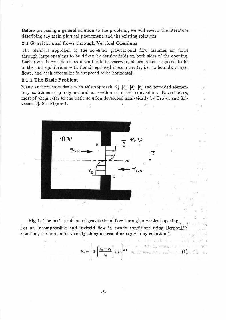
Before proposing a general solution to the problem, , we will review the literature describing th~ main physical phenomena and the existing solutions.
2.1 Gravitational flows through Vertical Openings
The classi.qal approach of the so-called gravitational flow assumes air flows . through large openings to be driven by density fields on both sides of the opening. Each room is considered as a; semi-infinite reservoir, all walls are supposed to be in thermal equilibrium ,with the air eµ,close,d in each cavity, i.e. no boundary layer flows, and e~ch streamline is supposed' to be horizontal..
2.1.1 The Basic Problem
Many authors have dealt with this approach [2] ,[3] ,[4}' ,[5] and provided elemen-. . , tary solutions of purelY. natural convection or mixed conyection. Nevertheless, most of the,!Il refer to the basic solution developed analytically by Brown and Sol-vason [2]. See Figure 1. ·' c ··
.1 ...
. oim,H ..•
• m' O,ZN
• 1 · . ·,
Fig 1: The basic problem of gravitational flow through. a vertical opening. . . .• :
For an incompressible and ·inviscid flow in steady conditions . using Bei:noulli's equation, the horizontal velocity along a streamline is given by equation I.
[ [Po - P·] l Vz = 2 Po ' g : ", o.q
. .!, ~ : .. '· • • t • ,
(1).
-.'.)-
. .
. • .
. l,
C>' " i
The mass flow below the neutral plan is obtained directly by integration (equation 2)
ZN
m'o,ZN =Cd J Po V, W dz 0
(2)
In equation 2, Cd is a phenomenological coefficient called discharge coefficient. It takes into account the local contraction of the flow due to the presence of opening.
The position of the neutral plan ZN is defined by writing the mass conservation through the opening which lead to equation 3.
ZN [ P; l .l H- ZN= Pa 3 (3)
At the end a direct integration delivers the value of the mass flow (equation 4 ). ·•
m' . = Cd W ( 8 g H3 P~ ~p ) o.6 0,ZN 3 I (4)
Where
(5)
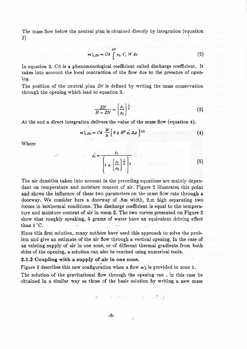
The air densities taken into account in the preceding equations are mainly dependant on temperature and moisture content of air. Figure 2 illustrates this point and shows the influence of these two parameters on the mass flow rate through a doorway. We consider here a doorway of .8m width, 2.m high separating two rooms in isothermal conditions. The discharge coefficient is equal to the temperature and moisture content of air in room 2. The two curves presented on Figure 2 show that roughly speaking, 5 grams of water have an equivalent driving effect than 1 ·c. Since this first solution, many authors have used this approach to solve the problem and give an estimate of the air flow through a vertical opening. In the case or an existing supply of air in one zone, or of different thermal gradients from both sides of the opening, a solution can also be reached using numerical tools.
2.1.2 Coupling with a supply of air in one zone . ... Figure 3 describes this new configu.ration when a flow m'.s is provided to zone 1.
The solution of the gravitational 'fl.'c>w through the opening can , , 1n this case be obtained in a similar way as those of the basic solution by writing a new mass
·' '. ,.

0.20 m' [Kg/s]
0.15
0.10
0.05
6. T [°C] 0.5 1.5 2 2.5 3
0.00 ....------'----+----'----+---------'---~ 0 5 10 15
6.HY x 103 [Kg/s] I •
Fig. 2: Gravitational flows due to temperature or moisture difference.
' ::;. I
..
. '•.
: r :..· •
• • • . .rt ~ ... l
' ·
Fig. 3 : Supply of air in one zone
-7-
balance equation through the opening .,
ms - m 112 + m 121 = 0 (5)
where m '12 represents the flow going from zone 1 to zone 2, and m '21 the flow from zone 2 to zone 1.
Then
ZN - Pi 2 ZN 2
[
3 .!. [ I.!] m'N ( H) 2 - ("Po) 1- H +ms= o (6)
With
' [ fl 3 2 a 2 -m N = - Cd Po W 2 g ~ H2
3 Po (7)
Equation 6 can be solved by using a Newton method in few iterations. The integration of the velocity field between the neutral plan and the limits of the opening then delivers the values of the air flow.
ZN [m] m· [Kg/s]
0.08 1.5
o.oe
o.s ZN == f(m' 5) _/ 0.02
o+-~~~~-.-~~~~-.-~~~~-.-~--,,....~
0 5 10 15 20 m· s x 102 O<g/s]
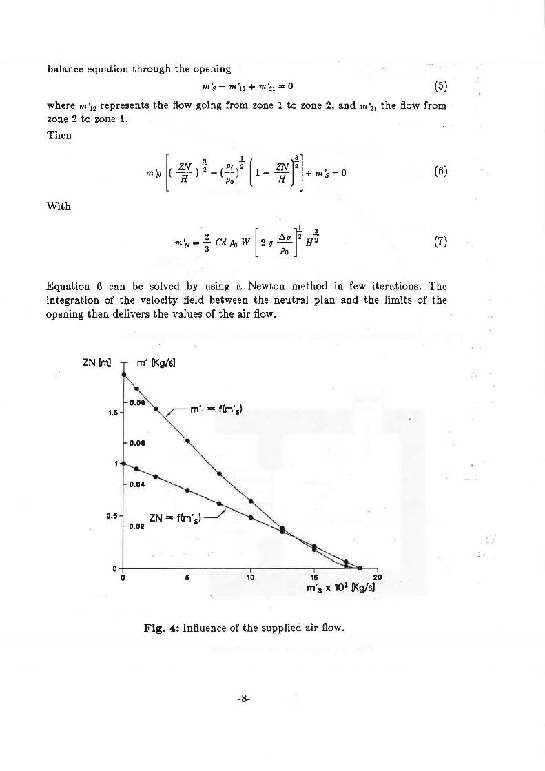
Fig. 4: Influence of the supplied air flow.
-8-
I '
. I
i:.•
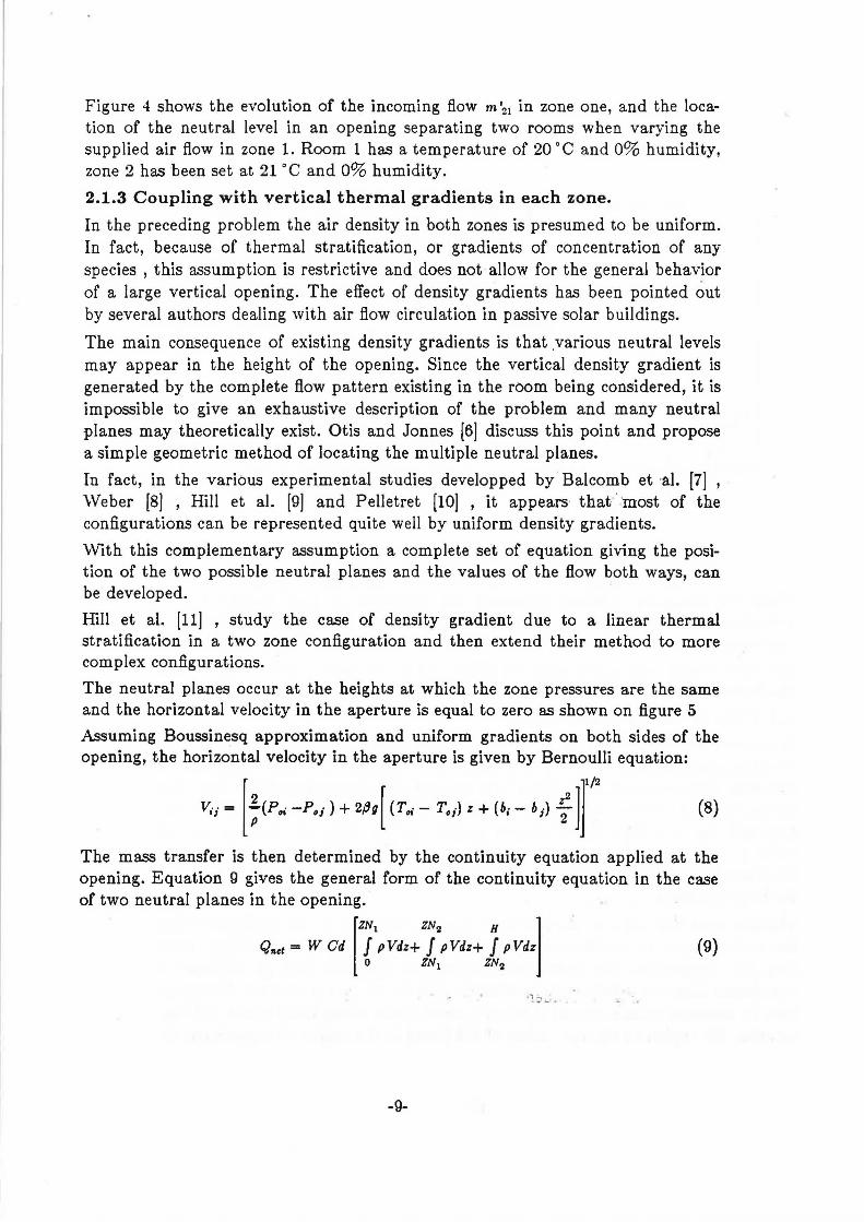
Figure 4 shows the evolution of the incoming flow m '21 in zone one, and the location of the neutral level in an opening separating two rooms when varying the supplied air flow in zone 1. Room 1 has a temperature of 20 °C and 0% humidity, zone 2 has been set at 21 °C and 0% humidity.
2.1.3 Coupling with vertical thermal gradients in each zone.
In the preceding problem the air density in both zones is presumed to be uniform. In fact, because of thermal stratification, or gradients of concentration of any species , this assumption is restrictive and does not allow for the general behavior of a large vertical opening. The effect of density gradients has been pointed out by several authors dealing with air fl.ow circulation in passive solar buildings.
The main consequence of existing density gradients is that ,various neutral levels may appear in the height of the opening. Since the vertical density gradient is generated by the complete fl.ow pattern existing in the room being considered, it is impossible to give an exhaustive description of the problem and many neutral planes may theoretically exist. Otis and Jonnes [6] discuss this point and propose a simple geometric method of locating the multiple neutral planes.
In fact, in the various experimental studies developped by · Balcomb et ·al. {7] , \Veber [8] , Hill et al. [9] and Pelletret [10] , it appears that · ·most of the configurations can be represented quite well by uniform density gradients.
vVith this complementary assumption a complete set of equation giving the position of the two possible neutral planes and the values of the flow both ways, can be developed.
Hill et al. [11] , study the case of density gradient due to a linear thermal stratification in a two zone configuration and then extend their method to more complex configurations.
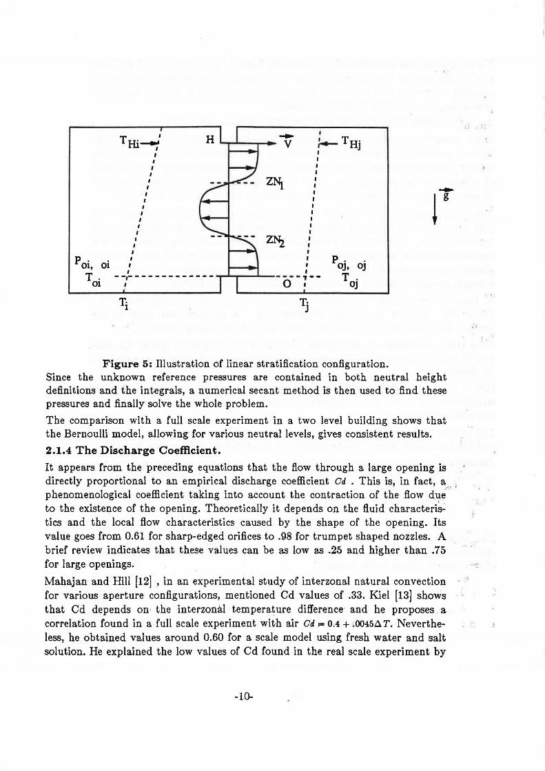
The neutral planes occur at the heights at which the zone pressures are the same and the horizontal velocity in the aperture is equal to zero as shown on figure 5
Assuming Boussinesq approximation and uniform gradients on both sides of the opening, the horizontal velocity in the aperture is given by Bernoulli equation:
[ ]1~
V.; = ;(P.,. -Po;)+ 2,8g[ (T.,.- To;) z + (6;- b;) ~2 l (8)
The mass transfer is then determined by the continuity equation applied at the opening. Equation 9 gives the general form of the continuity equation in the case of two neutral planes in the opening.
[
ZN1 ZN2 H l Qnet = W Cd J pVdz+ J pVdz+ J pVdz
0 ZN1 ZN2
(9)
-9-
poi, oi T.
01
I
T Hi_..' H ........ ---· V I
I I I
~TH· I j I I
I I I I
I I
ZNi_ I I
I I
I I I I
I I I I I I I I I
I I
I I I
I I I I --,- ------------...,...........,_ ....... __ ---~ --
I 0 I
T.· 1 T.· J
poj, oj T.
OJ
Figure 5: Illustration of linear stratification configuration. Since the unknown reference pressures are contained in both neutral height definitions and the integrals, a numerical secant method is then used to find these pressures and finally solve the whole problem.
The comparison with a full scale experiment in a two level building shows that the Bernoulli model, allowing for various neutral levels, gives consistent results.
2.1.4 The Discharge Coefficient.
It appears from the preceding equations that the flow through a large opening is directly proportional to an empirical discharge coefficient Cd • This is, in fact, a . , phenomenological coefficient taking into account the contraction of the flow du~ · · ' to the existence of the opening. Theoretically it depends on the fluid characteri~ tics and the local fl.ow characteristics caused by the shape of the opening. Its value goes from 0.61 for sharp-edged orifices to .98 for trumpet shaped nozzles. A brief review indicates that these values can be as low as .25 and higher than .75
.'I
for large openings. ·:
Mahajan and Hill [12] , in an experimental study of interzonal natural convection for various aperture configurations, mentioned Cd values of .33. Kiel [13] shows that Cd depends on · the interzonal temperature difference- and he proposes . a correlation found in a full scale experiment with air Cd ;:= 0.4 + >0045~ T. Nevertheless, he obtained values around 0.60 for a scale model using fresh water and salt solution. He explained the low values of Cd found in the real scale experiment by
-10-
!.
t.
pointing out an important interfacial mixing at low temperature differences. The higher values given by the model are due to a lower Reynolds number. This leads to a more stable flow and decreases the interfacial mixing effect. These conclusions contradict Riffat's results [14] discharge coefficient with interzonal temperature differences. Cd decreases from 0.6 for a temperature difference of lK, to 0.25 for lOK. It becomes clear that more precision is needed in the definition of the discharge coefficient, and in the experimental conditions of its determination. More recently, Vari Der ~-lass et al. [15] , reproducing the Lane-Serff et al. [16] experiments, concluded that the discharge coefficient corresponding to the Bernoulli model can reasonably be taken as being between _0.6 and 0.75. However a precise determination remains very difficult.
2.2 Natural Convection Approach
Since one of the main consequence of large opening behavior, pointed out in recent decades, was their influence on the thermal behavior of buildings, many authors have looked for empirical correlations giving the total heat transfer rate through the opening as a function of its geometry and of the thermal state of each zone.
Barakat [17] gives a wide review of existing correlations and remarks that heat transfer through a large opening of height H can be expressed by a correlation in the form of equation 10,
NuH -- = C Grfr
Pr (10)
where b is approximately 0.5, and C lies between .22 and .33 depending on the temperature difference taken into account as reference. The temperature difference used to define the Grashof number is taken as the difference between the average room temperatures.
Nevertheless, this result includes different problems, from Bernoulli's flow problems described by Brown and Solvason [2] , to flow patterns driven by boundary layer flows as described in the Nansteel and Greif [18] experiments.
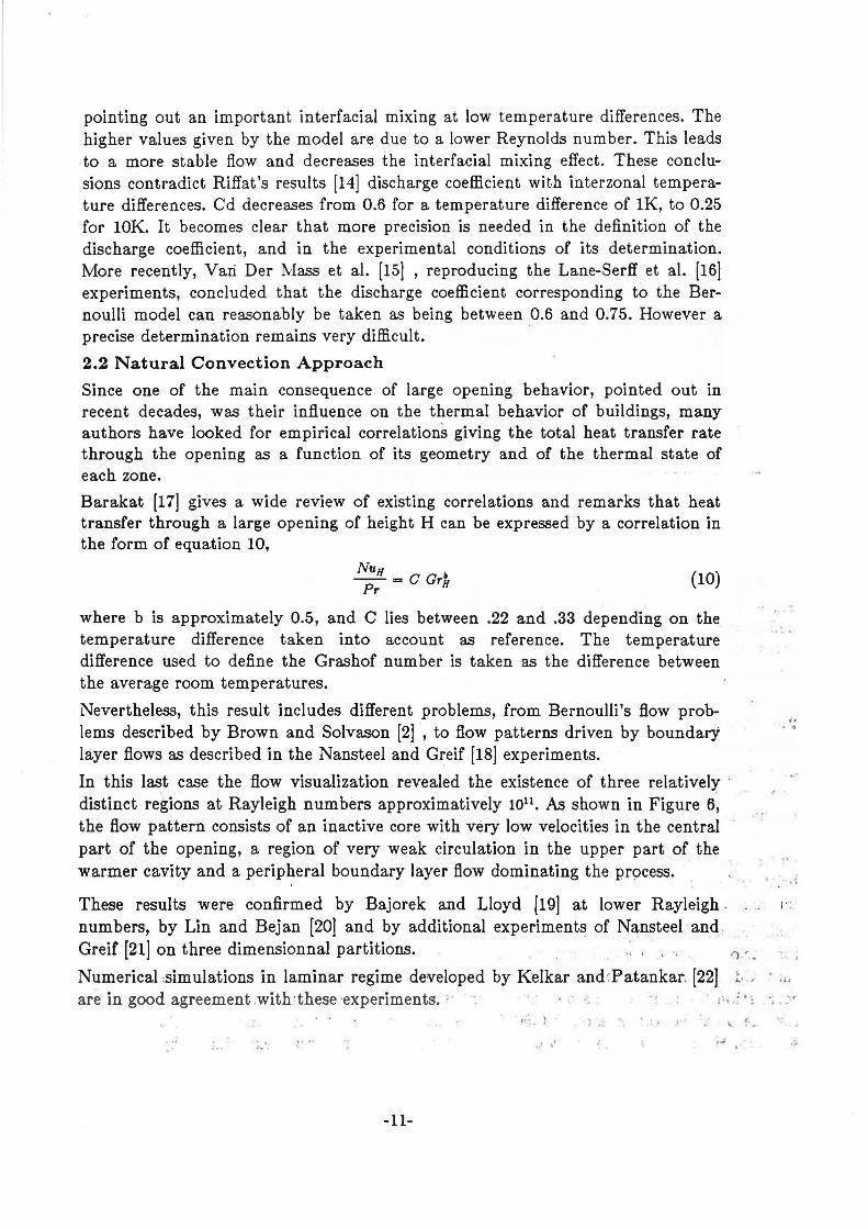
In this last case the flow visualization revealed the existence of three relatively · distinct regions at Rayleigh numbers approximatively 1011 • As shown in Figure 6, the fl.ow pattern consists of an inactive core with very low velocities in the central part of the opening, a region of very weak circulation in the upper part of the warmer cavity and a peripheral boundary layer flow dominating the process.
These results were confirmed by Bajorek and Lloyd [19] at lower Rayleigh , numbers, by Lin and Bejan [20] and by additional experiments of Nansteel and . Greif (21] on three dimensionnal partitions. ,, , , "
.. .
r. , . ,. -
,, ..
. • ,{
1· :
Numerical ,simulations in laminar regime developed by Kelkar and:Patankar. [22] . ,, d•
are in good agreement .with ·these ·experiments; ' " · · i:. ! ·:
i .": .. : I I \. !-- ••
~-.. \ .....
-11-
I
Woll bOwftCIOr r IOJI' Tc ...
Fig. 6: Flow pattern observed by Nansteel and Greif [18] for 1010::;RaL::;1011
Most of the results reported by Barakat [17] are generally in good agreement with a Bernoulli's flow description, but the author reported that the correlations are much affected by the definition of the characteristic temperature difference.
However, Scott et al. [23] study more particularly the boundary layer driven regime and they demonstrate that boundary layers can transport a significant amount of energy through a large opening without large bulk fluid temperature differences.
This survey of studies of inter-zone convective heat transfer through large openings shows that very few boundary conditions have been studied, that most of the experiments were performed in scale models using fluids other than air, and that very few studies examined inter-zone heat transfer under combined natural and · forced convection. The resulting correlations can however, be used in specific cases to give the exchange flow between two zones by converting the heat transfer to mass flow rate using calorimetry equations.
2.3 Transient Flows and Turbulence Effects Through Vertical Openings
This class of problems usually contains two very different kinds of configuration.
• The transient behavior of. fio?Ys due to a slow evolution in time of boundary conditions.
-12-
.·
' \ l
. I
• The effect of turbulence or fluctuating pressure fields.
2.3.1 Transient Flows.
The first class of problem is usually solved with a steady state description of the dynamical process. Bernoulli's flow theory or any other correlation is used to calculate the steady state flow corresponding to the boundary conditions of each time step. The main assumption in this case is that the flow will be fully developed instantaneously and will follow the imposition of new boundary conditions at each time step.
The variation of the boundary conditions can be given by hourly variation of average wind speed and direction, by a schedule of occupancy or of the working of mechanical ventilation systems, or by the evolution in tim.e of the thermal state of the building itself.
The more common way to solve the problem is to combine the airflow model with others dealing with thermal simulation or any other phenomena driving the air flow process and to give a complete description of the couph~d problems.
However in some cases it is better to use a simpler approach and to give an estimate of the evolution in time of the flow through an opening caused by a single perturbation.
In this way Kiel and Wilson [24] studied the unsteady buoyancy flow that occurs during the door opening or closing period. They investigate the decrease in flow rate that results from the effect of limited interior volume and finally consider the effect of door pumping.
They use full scale experiments and scale model with fresh water and a salt solution to show that the transient flow due to the opening or closing of doors can be predicted using quasi steady equations and gravity current theory as defined by Benjamin [25]
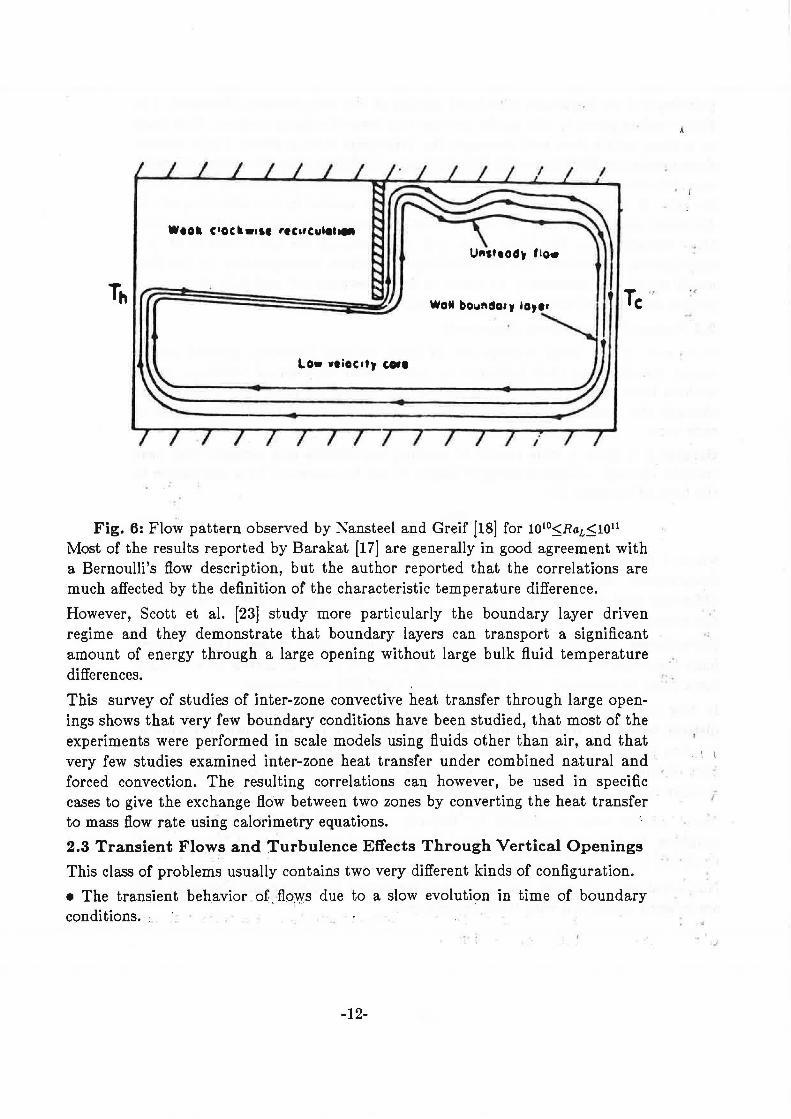
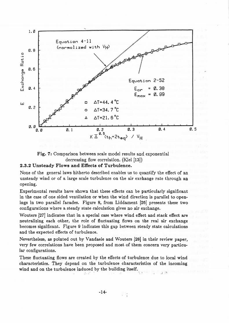
The decrease in flow rate due to a limited interior volume is well described by an exponential formulation of the exchange ratio (equation 11 ).
(11)
Where Ema.x represents the maximum exchange at infinite time, A and B are determined by the boundary conditions of equation 11. Figure 7 shows a comparison between this approach and the results obtained by Kiel [13] using his scale model.
Van Der Mass et al. [15] look at the same problem from a different aspect. They study the evolution of the airflow rate and temperature in a r90m wh~n op~ning a window. Assuming adiabatic walls and developing the ene_rgy balance ·of the inside air they show, by full scale experiments, that a reasonable agreement is obtained.
.. , . .. . ,. i •
The main advantage of such a solution is to avoid" the ' coupling-with .a, :real sim~ . ~ lation of the thermal behavior of the whole building and to give a quick estimate of the transient evolution of the airflow.
-13-
1. 0
0.8 0 ....
+> 0
Ck:
al 0. 6 01 c 0
..J:. 0 x 0. 4 w
w 0.2
Eguotion 4-11 (normalized with VH) .. .. .. . ··
.. .. .. .. .. .. . ·· ..
.... ·····"~. --... . .. · . .. ...
Eguotion
Ecr = Em ox =
D ~T=44.4°C
0 ~ T=34. 7 °C
6. ~T=21. 6°C
2-52
0.38 0. g·g
0. 3 0. 4 0.5 0.0 ~·L...i..--i.___...__..__'--._...1-...i.........L...~.....i..--i.---i~ ...... ._---------------"-------
0.0 0. 1 0.2 _ ra. s
(th+2t9 g) I VH K~
Fig. 7: Comparison between scale model results and exponential decreasing flow correlation. (Kiel [13])
2.3.2 Unsteady Flows and Effects of Turbulence.
None of the general laws hitherto described enables us to quantify the effect of an unsteady wind or of a large scale turbulence on the air exchange rate through an opening.
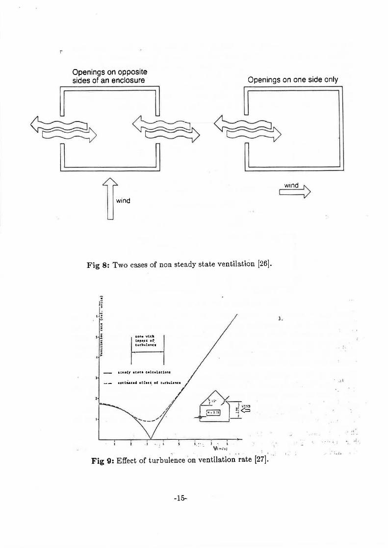
Experimental results have shown that these effects can be particularly significant in the case of one sided ventilation or when the wind direction is parallel to openings in two parallel facades. Figure 8, from Liddament [26) presents these two configurations where a steady state calculation gives no air exchange.
Wouters [27) indicates that in a special case where wind effect and stack effect are neutralizing each other, the role of fluctuating flows on the real air exchange becomes significant. Figure 9 indicates this gap between steady state calculations and the expected effects of turbulence.
Nevertheless, as pointed out by Vandaele and Wouters [28) in their review paper, very few correlations have been proposed and most of them concern very particular configurations.
These fluctuating flows are created by the effects of turbulence due to local wind characteristics. They depend on the turbulence characteristics of the incoming wind and on the turbulence induced by the building itself.
' ' I " ; . } ~ ~
-14-
r
Openings on opposite sides of an enclosure Openings on one side only
wind
Fig 8: Two cases of non steady state ventilation [26].
1one wt.ch
1 l•p•C. ot r ......... . 1e1.1~y ua.1:1 c•lculat1an1
11li~.u: 1d 1fhct. of tur!tuhnc1
. J • : ' I" , r , · . .
~ • - .. 4
Fig 9: Effect of turbulence on ventilation rate [27].
-15-
wind>
3.
. :I
. : .1 ..
.. ,. I •
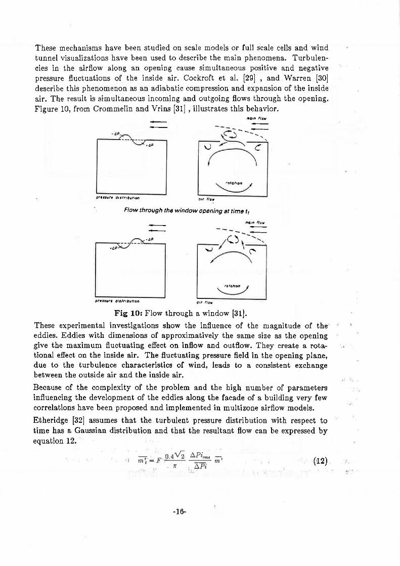
These mechanisms have been studied on scale models or full s'cale cells and wind tunnel visualizations have been used to describe the main phenomena. Turbulencies in the airflow along an opening cause simultaneous positive and negative pressure fluctuations of the inside air. Cockroft et al. [29] , and Warren [30] describe this phenomenon as an adiabatic compression and expansion of the inside air. The result is simultaneous incoming and outgoing flows through the opening. Figure 10, from Crommelin and Vrins [31] , illustrates this behavior.
•0111 flow
·4P
·~P
gr111ur1 d11fr1but1on a,,. flaw
Flow through the window opening at time t,
mom now
-~P .....----------------
pru1ur• di1lr10uhon air !tow
Fig 10: Flow through a window [31].
These experimental investigations show the influence of the magnitude of the eddies. Eddies with dimensions of approximatively the same size as the opening give the maximum fluctuating effect on inflow and outflow. They create a rotational effect on the inside air. The fluctuating pressure field in the opening plane, due to the turbulence characteristics of wind, leads to a consistent exchange between the outside air and the inside air.
Because of the complexity of the problem and the high number of parameters influencing the development of the eddies along the facade of a building very few correlations have been proposed and implemented in multizone airflow models.
Etheridge [32] assumes that the turbulent pressure distribution with respect to time has a Gaussian distrib1:1tion and that the resultant flow can be expressed by equation 12.
· J - 0 4\/2 ~Pi,..,., -m~=F· · m'
- 7r ~Pi :· :L
(12)
-16-
..
I, ...
~ ·
vVbere F is a linear function accounting for large mean pressure differences ~Pirm, is the root mean square pressure difference across the opening and Qma represents the steady state flow rate.
Cockroft and Robertson [29] show that assuming an isotropic turbulence and using Gaussian probability distributions for wind velocity and flow rate gives a good agreement with experimental results obtained in a simulated wind.
In order to integrate this turbulence effect in a more general air flow model, Phaff and De Gidds [33] propose an empirical correlation deduced from experimental work and give a general definition of the ventilation rate through an open window as a function of temperature difference, wind velocity and fluctuating terms. Since they found an existing flow without either wind or temperature difference a fix turbulent term was added to the volumic fiow. This turbulent term is presented as an additional pressure drop written as a function of the flow exponent,
Pt = .01 [ 1 ~ n r (13)
If the flow is fully turbulent ( n = 0.5) the alternating flow through one half of the opening can be defined by equation 13.
1
CdAel! ( )2 Qv,..c = 2
0.001 V2 + 0.0035H~ T + .01 (14)
These types of models, combining the effects of wind velocity, temperature difference and turbulence, should be able to predict the effect of fluctuating wind on the air flow exchange through an external opening in a multizone pressure network. However, much more work is now needed in order to give a precise description of the effects of the many parameters influencing the strncture of the local wind at the very location of the opening.
2.4 Horizontal Openings
To complete the description of the various problems found in defining large opening behavior, horizontal openings must be studied.
The most interesting aspect of horizontal openings is that in which the fluid above the opening has a greater density than the fluid below. In this case an unstable condition is reached and an exchange occurs between the lighter fluid flowing upward and the heavier flowing downward.
Figure 11 describes this configuration.
This problem was first studied by Brown [34] , but few authors have made a con-sistent contribution towards solving it. ·
' ·'
In a recent paper Epstein [35] discus5es the buoyancy exchange flow through small openings in horizontal partitions. He presents an experimental study using brine above the partition and fresh water below the , p·artition· and identifies four different regimes as the aspect ratio of the opening is increased.
-17-
·,
, . . .
_ t - '
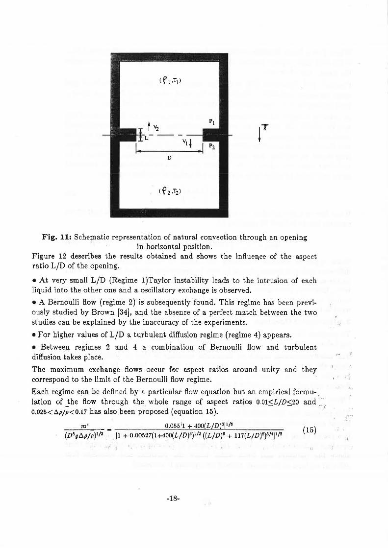
Fig. 11: Schematic representation of natural convection through an opening ' in horizontal position.
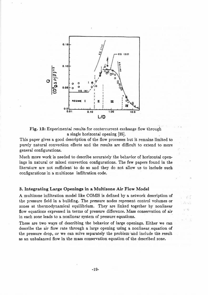
Figure 12 describes the results obtained and shows the influen,ce of the aspect ratio L/D of the opening.
• At very small L/D (Regime 1 )Taylor instability leads to the intrusion of each liquid into the other one and a oscillatory exchange is observed.
• A Bernoulli flow (regime 2) is subsequently found. This regime has been previously studied by Brown (34], and the absence of a perfect match between the two studies can be explained by the inaccuracy of the experiments.
•For higher values of L/D a turbulent diffusion regime (regime 4) appears.
• Between regimes 2 and 4 a combination of Bernoulli fl.ow and turbulent diffusion takes place.
The maximum exchange flows occur fe>r aspect ratios around unity and they correspond to the limit of the Bernoulli fl.ow regime.
Each regime can be defined by a particular flow equation but an empirical formu- <
lation of the flow through the whole range of aspect ratios O.Ol~L/D~20 and'.~·. 0.025<.6.p/p<0.17 has also been proposed (equation 15). · _,
m' = 0.055[1 + 400(L/D)3]1/e (D 6g.6.p/p)112 • [1 + 0.00527(1+400(L/D)3)1/2 ((L/D)e + 117(L/D)2)3/4]1/a (l
5)
,,
-18-
::.-·
.•
,_
0 . 11
N 0 . 10 .. --~ -0
Q,,.
<1 0 0
000 0 .05 0 0
c -AEOIME I
10.0
L/O
Fig. 12: Experimental results for contercurrent exchange flow through a single horizontal opening [35].
This paper gives a good description of the flow processes but it remains limited to purely natural convection effects and the results are difficult to extend to more general configurations.
Much more work is needed to describe accurately the behavior of horizontal openings in natural or mixed convection configurations. The few papers found in the literature are not sufficient · to do so and they do not allow us to include such con.figurations in a multizone infiltration code.
3. Integrating Large Openings in a Multizone Air Flow Model
A multizone in.filtration model like CO:MIS is defined by a network description of the pressure field in a building. The pressure nodes represent control volumes or zones at thermodynamical equilibrium. They are linked together by nonlinear flow equations expressed in terms of pressure difference. Mass conservation of air in each zone leads to a nonlinear system of pressure· equations.
These are two ways of describing the behavior of large openings. Either we can describe the air flow rate through a large opening using a nonlinea~ . equation of the pressure drop, or we can solve separately the problem.:and include the result as an unbalanced flow in the mass conservation equation of the described zone.
-19-
.·
i~
3.1 Existing Solutions
To represent the behavior of a large opening in an air flow model we can take an explicit definition of the flow given by a Bernoulli flow regime assumption or any other correlation. In the case of both methods the large opening is disconnected from the general pressure network it is solved separately and then represented by an unbalanced flow in the mass conservation equation of each zone. Since the flow is strongly dependent on the pressure field around and inside the building the first solution will lead to a high number of iterations and a direct approach appears more attractive.
To connect the large openings to the general pressure network, it is necessary to define their behavior in terms of nonlinear equations of the pressure drop. The first possibility is to describe the large opening as a conjunction of parallel small openings, properly located, and with only a one way flow allowed for each one. Each small opening is then described by a crack fl.ow equation taking into account the local pressure drop. The whole system of nonlinear equations can be introduced directly into the pressure network.
This solution was first proposed by Walton [36] and Roldan [37] and has been used in various multizone models developed since (Feustel [38] ). It leads to the definition of various flow elements in simulating one large opening.
A second way to solve this problem is to interpret the flow equations of large openings in terms of non linear pressure laws. This method leads to the definition of new flow equations in pressure characterizing the behavior of large openings.
Walton [39] proposed this solution in the case of a vertical opening between two isothermal zones i and j for steady state flow. Following the approximation of the Bernoullis' flow it is assumed that the velocity of the airflow at different heights is given by the orifice equation (equation 16)
[ . . ]1/2
Vij(z) = 2 Pi(z) ~ P1(z) (16)
where p represents the density of flowing air.
The hydrostatic equation is then used to relate the pressures in each room to the air densities at various height, and the v~locity equation becomes
[ ]I~
Vij(z)= 2 [(Pio-Pio)~gz(p;-P;) l (17)
The height of the neutral plane is given by Pi(z) = Pj(z) or by setting the interzonal velocity to zero.
In the case of a neutral plane being located in the opening and taking this point as origin for altitude, since Pi(zn) = Pj(zn), the mass flow through the doorway above and below the neutral level ZN are given by equations 18 and 19.
-20-
..
:•H-:1&
m~n.H =Cd I p Vij(z) W dz (18) z-0
:-0
m 'o,zro = Cd I p Vij(z) W dz (19) z-z•
Walton [39J reports that this model of doorways tends to be faster than the multiple opening approach. However it complicates the assembly process of the network since one or two flows may exist through the same link between two zones.
3.2 CO:MIS Contribution
The main objective in proposing a solution for large openings is to fit it easily into the network definition and to go as far as possible in the modeling of the various phenomena influencing the behavior of large openings.
The main ·assumptions of our model are:
•Steady flow, inviscid and incompressible fluid
•Linear density stratification on both sides of the opening
• Turbulence effects represented by an equivalent pressure differ.ence profile
• Effects of reduction of the effective area of the aperture represented by a single coefficient. -~ ; l· • " .
3.2.1 General numerical solution of the problem
Figure 13 gives a general description of the problem to solve.
On each side of the opening, we assume a linear density stratification
.'/ ; .
(20)
and we introduce a linear pressure difference simulating the effect of turbulence.
(21)
The reference pressures on each side are given at the bottom of the opening. Assuming Bernoulli hypothesis on both sides of the opening, we can define the pressure difference at any level z as
P 1(z)-P2(z) = (Po1-P02)-g[(Po1 z.+ b1 ~2 )-(p02 z + b2 ~2 ) r(P10+b1 z) (22) .
The velocity at any level z is then given by
V(•) = [ 2 [ P,(•) ~ P,(•) l r (23) .
where p represents the density transported. by the ·veloci~y. " > l
.. . , i .....
• l
-21-
.. .
I: ,,::..
·: . ..
Pi (z) = p tO +b cZ Z
f'1(z)= p\J ' I
I
' I
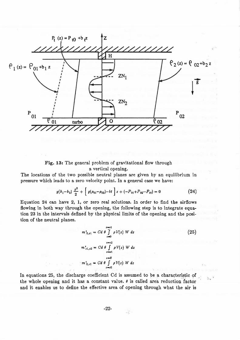
Fig. 13: The general problem of gravitational flow through a vertical opening.
The locations of the two possible neutral planes are given by an equilibrium in pressure which leads to a zero velocity point. In a general case we have:
(24)
Equation 24 can have 2, 1, or zero real solutions. In order to find the air.flows fl.owing in both way through the opening, the following step is to integrate equation 23 in the intervals defined by the physical limits of the opening and the position of the neutral planes.
z-zl
m'o,zi =Cd fJ J pV(z) W dz (25)
Z'•Z2
m~1.z2 =Cd fJ J pV(z) W dz
z-H
m'o,z1 =Cd fJ J pV(z) W dz Z•z2
In equations 25, the discharge coefficient Cd is assumed to ~e a charayteri~tic 9f , the whole opening and it has a constant value. 8 is called area reduction .. factor and it enables us to define the effective area of opening through what the air is
-22-
' . ..
flowing.
In the more general case, these integrals have no analytical solutions and they have to be computed by a numerical mean. In CO.MIS, we use a classic Simpson integration. This numerical solution is general, but it is also time consuming and we reserve it to the more general case. In fact as far as equation 24 remains a linear one (i.e. when no density gradients exist), an analytical solution does exist and we can use it to save computational time.
3.2.2 Analytical solution of the problem without density gradients
If we now assume that air density in each zone does not change with altitude, an analytical solution does exist. The pressure difference at any given level Z becomes
P,.(z)-P2(z) = (Po1-P02) - g (Poi z - P02 z) + (Pt0+b1 z)
The position of the possible neutral plane is then given by
(Po1-Po2+Pt0) ZN=-----
g (Po1-Po2) - b,
and the velocity at any location Z is given by 1/2
[ [
(Po1 - Po2+Pt0) - [u (Po1-P02) - b,] z l V(z) = 2
p
(26)
(27)
(28)
Taking the position of the neutral plane as origin for the Z axis, equation 28 becomes
1/2
V(z) = ~ [-[u (Po1-PP02) - b,] z l (29)
and the flows through the large opening are given by direct integration of equation 29 between 0 arid the limits of the opening. In a general case, we have
.!. 3
m'zN,H= ! WCdoYp(2g ~Po1-Po2-b1 1 )2
IH-zN/2 (30)
and
.!. 3
m'o,zN= ~ WCdoYp(2u IP01-P02-b11)2
IZN/2 (31)
In equations 30 and 31, p represents the density transported by the flow and 8
represents the _area reduction factor delivering the effective area of the, openin_g.
3.2.3 Examples of solutions . , · '· .. : ~ . • r- . r: ~ , ~ . .
-23-
. ' . ' '
·' I l "'
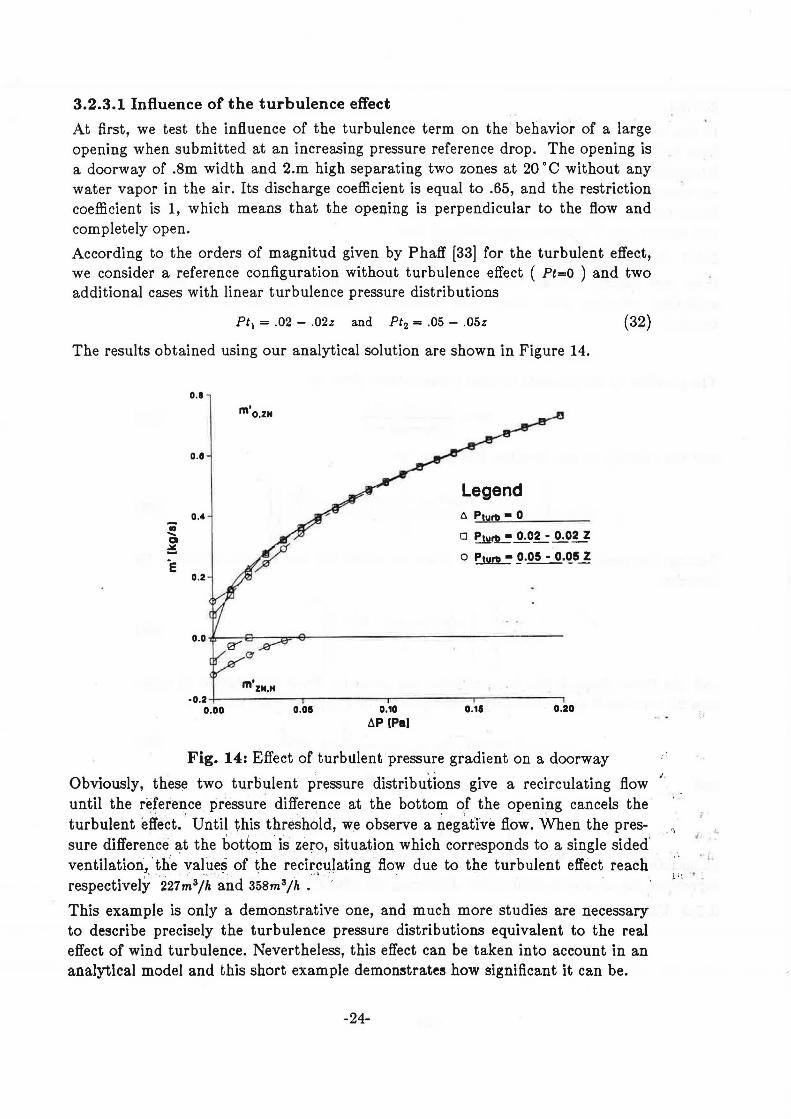
3.2.3.1 Influence of the turbulence effect
At first, we test the influence of the turbulence term on the behavior of a large opening when submitted at an increasing pressure reference drop. The opening is a doorway of .Sm width and 2.m high separating two zones at 20 ° C without any water vapor in the air. Its discharge coefficient is equal to .65, and the restriction coefficient is 1, which means that the opening is perpendicular to the flow and completely open.
According to the orders of magnitud given by Phaff [33) for the turbulent effec.t, we consider a reference configuration without turbulence effect ( Pt=O ) and two additional cases with linear turbulence pressure distributions
Pt1 = .02 - .02z and Pt2 = .05 - .05z
The results obtained using our analytical solution are shown in Figure 14.
0.1
m'o,zN
0.1
Legend 0.4 ~ Pturb • 0
o P1urt1 • ~O.!.: o.og o Pturb • !J.05 • 0.1!5 ~
0.2
m'zN,H •0.2 +-----....--------.--------...-------,
0.00 0.08 0.10
6P (Pal 0.18 0.20
(32)
Fig. 14: Effect of turbulent pressure gradient on a doorway
Obviously, these two turbulent pressure distributions give a recirculating flow until the reference pressure difference at the bottom of the opening cancels the turbulent effect . . Until this threshold, we observe a neg~trve flow. When the pressure difference at the bottom. is zero, situation which corresponds to a single sided' ventilation, 'the vafoes of the recirculating flow due to the turbulent effect reach respectively '221~3fh and 358m3/h .·i · ·
This example is only a demonstrative one, and much more studies are necessary to describe precisely the turbulence pressure distributions equivalent to the real effect of wind turbulence. Nevertheless, this effect can be taken into account in an analytical model and this short example demonstrates how significant it can be.
-24-
• 'i '-
• l.

3.2.3.2 lnfl~ence of density gradients
The second example we present is the behavior of the same doorway previously defined, but we put on one side a stratified environment. The temperature of zone 2 is set at 20 °C and in zone 1 the reference temperature at the bottom of the opening is 17.5 °C with a density gradient of - .lkg/m 4 which gives us a dry air temperature of 22.5 ·c at the top of the opening. On the same side we keep the effect of a turbulence effect Pt 1=.02 - .02z • Figure 15 represents the evolution of the flows c'alculated by our numerical solution when varying the reference pressure difference at the bottom of the opening.
0.1
0.4
• m ' 11
0 ~1--0.2
.. ..... a o.o ~ / ·e / /
·0.2 / /
/ /
·0.4 / /
/ ,,.,....,,.,.... ./ -·0.1
0.01 ·0.10 ·O.OI o.oo 0.10
6P11 [Pal
Fig. 15: Effect of density gradient on one side of a doorway
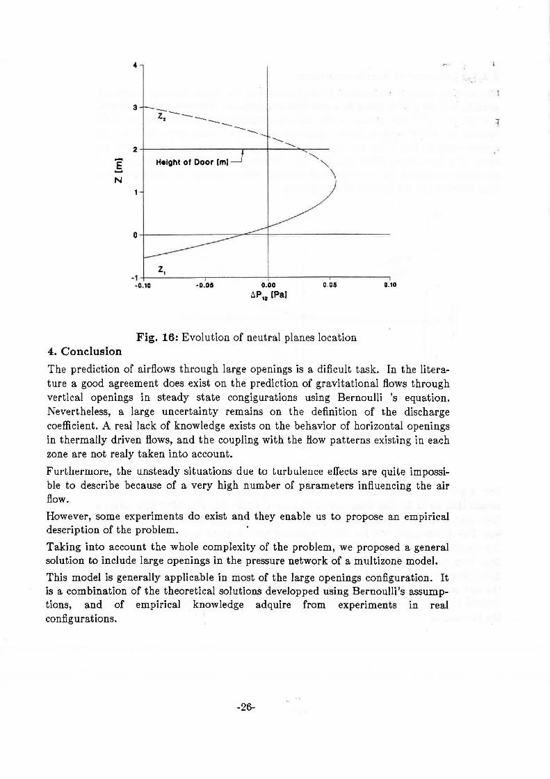
For negative pressure differences, we obtain a negative one way flow ( which means that air is flowing from zone 2 to zone 1) until -.015 Pa. After this value, a first neutral plane appears at the bo,ttom; of the opening. After -.015 Pa, a two way flow exists until .025 Pa where a second neutral plane appea~ , at the top of, .. the opening. The existence of the second neutral plane incr~ases . significantly , the (. ' flow from zone 1 to zone 2. Then, both neutral planes disap'ear and the negative flow ( from zone 2 to zone 1 ) too. Figure 16 ~how~ the evolution. of t:q.e' position of ·:
111
(
the two neutral planes in this configuration. This curve is .the horl,zontal parabola ~ ' ' r ~ ~ • . J " .. •
defined by Equation 24 when varying the reference pressure differenc~ be~ween ,, : ··' . ' \' the two zones. · · · - . J~. ·,
~ ,~ .. ( ;;.._ ·':I Jr :--._ ' •·: ~ "r: I I
·. '~ 'I r; o.
r ,• . .! 1 , (,'Ji
.t: :.' t ~ ' :.: ., ... J ; '.'. . .,
' . -25-
E' .... N
4. Conclusion
4
--z, -----------3
............ 2 -1-~~~~~~~-r-~-;--~-.......~....-~
Height of Door lml
z, - 1 4--~~~~-.--~~~~-1-~~~~"'T"""-*~~~----,
·0.10 ·0.05 0.00
t.P,2 [Pa) 0.05
Fig. 16: Evolution of neutral planes location
0.10
The prediction of airflows through large openings is a dificult task. In the literature a good agreement does exist on the prediction of gravitational flows through vertical openings in steady state congigurations using Bernoulli 's equation. Nevertheless, a large uncertainty remains on the definition of the discharge coefficient. A real lack of knowledge exists on the behavior of horizontal openings in thermally driven flows, and the coupling with the flow patterns existing in each zone are not realy taken into account.
FurL11ermore, the unsteady situations due to turbulence e[ecLs are quHe impossible to describe because of a very high number of parameters influencing the air flow.
However, some experiments do exist and they enable us to propose an empirical description of the problem.
Taking into account the whole complexity of the problem, we proposed a general solution to include large openings in the pressure network of a multizone model.
This model is generally applicable in most of the large openings configuration. It is a combination of the theoretical solutions developped using Bernoulli's assumptions, and of empirical knowledge adquire from experiments in real configurations.
-26-
1
However, much more work is needed to validate the assumptions we had to make. Parametric studies coupled with specific experiments are now necessary to check the validity of our solution and show the effect of the different parameters involved in the model.
Further studi·es should also include the effects of coupling between the large opening flow and other flow patterns caused by natural or mixed convection in buildings.
c
' ..
J· .• (. i .
' . "
l. <. j )
.:,1.:: .. 1.
I ' ' ; : ", J:. ·~ = ! "> ) l (
• I I ' I " .
• t ) I ,,
- , · I
-27-
References
1. Feustel, H. E. and Kendon, V. M., " Infiltration models for multicellular structures. A literature review. ", Energy and Buildings, Y,ol. 8, N 2, pp 123-136, 1985.
2. Brown vV. G. and Solvasson K. R., " Natural convection through rectangular openings in partitions. 1- Vertical Partitions", Int. J. Heat and Mass Transfer, Vol 5, pp 859-868, 1962.
3. Shaw B. H. and Whyte W., "Air movement through doorways The influence of temperature and its control by forced airflow", Building Services Engineers, Vol 42, N 12, pp 210-218, 1974.
4. Shaw B. H., " Heat an4 mass transfer by convection through large rectangular openings in vertical partitions", Ph. D. Thesis, University of Glasgow, UK, 1976.
5. Lidwell . 0. M;., " Air exchange through doorways. The effect of temperature. diffepen~e, tµrbulence and ventilation flow", J. Hyg. Camb., Vol 79, pp 141-154, 1977.
6. Otis1
D.R. 'and Jones G.F., " Neutral planes in stratified, thermally driven multiple room e~closures", Solar Energy, Vol 40, N 2, pp 135-137, 1988.
·.
7. Balcomb J.D. and Yamaguchi K., " Heat distribution by natural convection,", Proc. gth Passive Solar Conf. pp 289-294, Santa Fe (N.M), 1983. . .....
, , I •• ~· ~ ·:1-
8. Weber D.D., " Similitude modeling of natural convection heaj; transfer.> through an aperture in passive solar heated building", Ph. D. Thesis, Los Alamos Scientific Laboratory report LA8385-r, 114 p, 1980~
g_
10.
11.
12.
. '
Hill D., Kirkpatrick A. and Burns P ., " Analysis and measurements of in-terzonaJ natural convection heat· transfer in buildings ", Transactions o_L AS:ME, Vol 108, pp 178-184, August 1986. .-
Pelletret R., " Inter-zone air movement an.d heat t~ansfer ~odeling", P~oc . . J
User 1'1. Work. q<?nf. SCS Int. KIH, ~sten~ (Belgium),! S_eptember 19~8.
Hill D.b., "Ailaiysis and measurements of interzonal convection in a passive solar building", Master Thesis, Colorado State University, Fort Collins
(Colorado), ~985. r.: :; _, .. 1 «: _1 :~,,: :~. ;_ ;~.'-... _.
~,i .. , l • . ·r~ ,.._ r:~.. . !! ~:. ·~· 4 ~! ··i ' ·. . ; ;
Mahajan R.M. and Hill D.D., Interzonal n~tqr~l, .cony~ct!on for various, f • · I . • .' ,.... ~· ,
-28-
aperture configurations ", AS:ME \Vinter Annual Meeting, Anaheim (California), 1986.
"' '
13. Kiel D.E., ""1-foa.Suring and mddeling airflow through doorways ", Master Thesis, University of Alberta, Edmonton (Canada), 1985.
14. Riffat S.B., II A study of heat and mass transfer through a doorway in a conventional house ", Research m Building .Group, Polytechnic Central London, (UK), January 1988.
. '
15. Van Der Mass J., Reulet C.A. and Hertig J.A., " Some aspects of gravity driven airflow through large aperture.s m building", ASHRAE Transac-tions, Vol 95, part 2, Up, 1989. · ''
16. Lane Serff G.F ., Linden P .F. and Simpson-J.E., " Transient flow through doorways produced by temperature differences", Roomvent 87, session 22, 1987.
17. Barakat S.A., " Inter-zone convective heat transfer in buildings; A review ", Journal of Solar Energy Engineering, Vol 109, pp 71-78, May 198'7~·· · ·'
l ! .. .
18. Nansteel N.W. and Greif R., " Natural convection in undivided and partially divided rectangular enclosures ", Journal of Heat Transfer, Vol 103, pp 623-629, November 1981.
19. Bajorek S.M and tr,1yod J.R., II Experimental investigation of natural c~nvection in partitioned enclosures" Journal of Heat Transfer, Vol. 104, pp 527-532, August 1982. · ·· · ·
20. Lin N.M. and Bejan A., ... Natural convection in a partially divided enclosure", Int. J. Heat and Mass Transfer, Vol 26, N 12, pp 1867-1878, 1983.
21.
22.
23.
Nansteel M.W. and Greif R., " An' investigation of natural conve:ction in enclosures with two and three dimensfonn:al ·partitions'', Int. J. Heat and Mass Transfer, Vol 27, N 4, pp 561-571, 1984 .
. , ' .• " 1 I I . . • ·. '~; ~ f~ • • I •' - ~ ' • ' . *
Kelkar K.M. and Patankar s~v:, Numerical prediction of riatura'l convec.:.· tion in partitioned enclosures", AS:ME Winter Annual Meeting, pp 63-71, 1987. ' . . .. '·;i .c '' :' - :!'' !ti"· ..
-.,: : I , :I ' ' :~ • I I -- '
Scott D., Anderson R. and Figliola R., II Blockage of natur~t: conv~ctrO'ri' boundary layer flow in a multizone enclosure",Jnt. J..". l!eat and Fluid Fl<?w,
· "'" - • ~ ~ r- " -, ' •; ( i - ··- · ' ~ · t
Vol"9, N 2, pp 2os.::21a, June 1988. · · "'· .; ·· _, J- ·
-29-
..
!.'. .
. '
'·.
24. Kiel D.E. and Wilson D.J., II Gravity driven flows through open doors", 7111
AIC Conf., paper 15, 16 p, Statford upon Avon (U.K.), 1986.
25. Benjamin T.B., " Gravity currents and rehlted phenomena", J Fluid Mecha., Vol 31, pp 209-248, 1968,
26. Liddament M.W., " Air infiltration techniques. An application guide", Air Infiltration and Ventilation Center report AIC-AG-1-86, 1986.
27. Wouters P ., " De ventilatieproblematiek in gebouwen", (The problematics of ventilation in buildings),·, DPvVB, National programma RD energie, 1987. ' '"-
28. Vandaele L and Wouter5 P., "Air flows through large openings. An overview of existing approaches", IEA Annex XX, Subtask 2 report, 20 p, May 1989.
29. Cockroft J.P. and Robertson R., Ventilation of an enclosure through a single opening", Building and Environment, Vol 11, pp 29-35, 1976.
30. Warren P.R., " Ventilation through openings on one wall only" Proc. Int. Heat and Mass Transfer Seminar, pp 189-206, Hemispher Publishing corp. Washington, 1977.
31. Crommelin R.D. and Vrins E.M.H, "Ventilation through a single opening in a scale model", Air Infiltration Review, Vol 9 , N 3, pp 11-15, May 1988.
32. Etheridge D.W., "Air leakage characteristics of houses. A new approach" BSER & T, Vol. 5, pp. 32-36, 1984.
33. Phaff H. and De Gidds W., "Ventilatie van gebouwen. Onderzoek naar de gevolgen van het opene n van ea raam op het binnenklimat van een kamer", (Building ventilation. Investigation of the consequences of opening one window on the internal climate of a room) IMG-TNO report C448, Delft (The Netherlands), 1980.
34. Brown W.G., "Natural convection through rectangular openings in partitions. 2- Horizontal partitions", Int. J. Heat and Mass Transfer, Vol. 5, pp 869-878, 1962.
35. Epstein M., " Buoyancy-driven exchange flow through small openings in
-30-
horizontal partitions", Journal of Heat Transfer, Vol 110, pp 885-893, No-vem her 1988. . i.: ·
36. Walton G.N., 11,A ;computer algorithm for predicting infiltration and interroom airflows", AS.BRAE Transactions, Vol go, part 1, rn84.
37. Roldan A., " Etude thermique et aeraulique, pes enveloppes de batiment. Influence des couplages interieurs et du )l,~ultizonage", ( Thermal and airflow study of the envelopes of buildings. Influence of internal couplings and multizoning effect ) Doc. Thesis, INSA de Lyon (France), 310p., 1985.
38. Feus~l H.E., "Mathematical modeling of infiltration and ventilation", 1011
AIVC Conference, Session 2, Espoo (Finland), September rnsg.
3g, Walton G.N., "Airflow network models for element based building airflow modeling", ASHRAE Summer, ,Annual Meeting, Symposium on interroom airflows, Vancouver (Canada),.'June 198g. . '"· I .
H l.
-.. . l,t
(' I
I r
r .
·' ~ . 1 . · ..
i ~ 1
-31-
, •,
'· _ ....
' I•
. • I
. ,. ·, :.-l . \' .. '• , . ..
I