
Experiment study on the burning rates of ethanol square pool fires affected by wall insulation and...
29
Accepted Manuscript Experiment study on the burning rates of ethanol square pool fires affected by wall insulation and oblique airflow Pei Zhu, Xishi Wang, Changfa Tao PII: S0894-1777(14)00285-4 DOI: http://dx.doi.org/10.1016/j.expthermflusci.2014.11.006 Reference: ETF 8349 To appear in: Experimental Thermal and Fluid Science Received Date: 25 August 2014 Revised Date: 21 October 2014 Accepted Date: 7 November 2014 Please cite this article as: P. Zhu, X. Wang, C. Tao, Experiment study on the burning rates of ethanol square pool fires affected by wall insulation and oblique airflow, Experimental Thermal and Fluid Science (2014), doi: http:// dx.doi.org/10.1016/j.expthermflusci.2014.11.006 This is a PDF file of an unedited manuscript that has been accepted for publication. As a service to our customers we are providing this early version of the manuscript. The manuscript will undergo copyediting, typesetting, and review of the resulting proof before it is published in its final form. Please note that during the production process errors may be discovered which could affect the content, and all legal disclaimers that apply to the journal pertain.
-
Upload
howtogetridofacneproblem -
Category
Documents
-
view
3 -
download
0
Transcript of Experiment study on the burning rates of ethanol square pool fires affected by wall insulation and...

Accepted Manuscript
Experiment study on the burning rates of ethanol square pool fires affected by
wall insulation and oblique airflow
Pei Zhu, Xishi Wang, Changfa Tao
PII: S0894-1777(14)00285-4
DOI: http://dx.doi.org/10.1016/j.expthermflusci.2014.11.006
Reference: ETF 8349
To appear in: Experimental Thermal and Fluid Science
Received Date: 25 August 2014
Revised Date: 21 October 2014
Accepted Date: 7 November 2014
Please cite this article as: P. Zhu, X. Wang, C. Tao, Experiment study on the burning rates of ethanol square pool
fires affected by wall insulation and oblique airflow, Experimental Thermal and Fluid Science (2014), doi: http://
dx.doi.org/10.1016/j.expthermflusci.2014.11.006
This is a PDF file of an unedited manuscript that has been accepted for publication. As a service to our customers
we are providing this early version of the manuscript. The manuscript will undergo copyediting, typesetting, and
review of the resulting proof before it is published in its final form. Please note that during the production process
errors may be discovered which could affect the content, and all legal disclaimers that apply to the journal pertain.

1
Experiment study on the burning rates of ethanol square pool firesaffected by wall insulation and oblique airflow
Pei Zhu1, Xishi Wang1,2*and Changfa Tao1,3
1State Key Lab. of Fire Science, University of Science and Technology of China, Hefei, 230026, China2 Anhui Province Center of Collaborative Innovation for City Public Security, Hefei, 230026, China
3Hefei General Machinery Research Institute, Hefei, 230031, China
*Corresponding author: Tel.: 86-551-63606437, Fax: 86-551-63601669, Email: [email protected]
Abstract: The effects of pool wall insulation condition and oblique air flow on the
burning rates of ethanol square pool fires have been studied experimentally in a
small-scale wind tunnel, which focused on the heat transfer process of the fuel pool
system due to flame tilt and wall insulation. The results showed that the mass burning
rate of a pool fire decreased when the pool wall was insulated, especially in the cases
with larger airflow speeds. The maximum value of the mass burning rate without wall
insulation reached approximately 2.3 times of that with wall insulation at an air speed of
2.93 m/s and a tilt angle of 0°. For both cases with or without wall insulation, the mass
burning rates decreased with increase in pool sizes and increased with increase in airflow
tilt angles. However, for the cases with wall insulation, the differences in the mass
burning rates with different pool sizes are relatively small as the airflow speeds exceed
1.5 m/s, while the differences are relatively large for the cases without wall insulation. In
addition, the turbulence of the flame fluid would be weakened when the pool wall was
insulated.
Keywords: Pool fire; Burning rate; Wall insulation; Oblique airflow; Heat transfer

2
NomenclatureL pool edge length (cm)A fuel surface area (m2)
pC specific heat (kJ kg−1K−1)m fuel mass (g)
'm& mass burning rate (gs-1)''m& mass burning rate per unit area (gm-2s-1)m²D & difference between with and without wall insulation (gm-2s-1)tiltedm²& mass burning rate per unit area with oblique airflow (gm-2s-1)
levelm²& mass burning rate per unit area with horizontal airflow (gm-2s-1)k value of tiltedm²
& / levelm²&
q tilt angle (°)gH gasification heat of the fuel (kJ kg−1)
vH latent heat of evaporation (kJ kg−1)evpQ& net energy to evaporate the fuel (kW)evp withoutQ -& net energy to evaporate the fuel without wall insulation (kW)
evp withQ -& net energy to evaporate the fuel with wall insulation (kW)
inQ& total heat transfer from the flame and surroundings to the fuel (kW)outQ& energy loss from the fuel to the surroundings (kW)fradQ& radiative heat transfer from flame to the fuel surface (kW)
fconvQ& convective heat transfer from the flame to the fuel surface (kW)
w fuelQ -& total heat transfer from the pool wall to the fuel (kW)
wfQ& heat transfer from the flame to the pool wall through the top surface (kW)
radQ& radiative heat transfer from the tilt flame to the pool wall outside surface (kW)convQ& convective heat transfer from the tilt flame to the pool wall outside surface (kW)condQ& conductive heat transfer from the tilt flame to the pool wall outside surface (kW)
1lossQ& heat loss from the fuel to the surroundings through the pool wall (kW)2lossQ& heat loss from the fuel surface to the surroundings through reradiation (kW)
v airflow velocity(m/s)T wall temperature with wall insulation(℃)
'T wall temperature without wall insulation (℃)t time (s)
Subscriptswith with wall insulationwithout without wall insulationf flamew pool walll leeward rims streamside rimw windward rim

3
1. Introduction
The fire hazards of liquid hydrocarbon fuels have been a serious safety concern, which
is attributed to liquid hydrocarbons being ubiquitous throughout society, including in oil
tanks, etc. A considerable number of studies [1-7] on both the practical and the
fundamental aspects of pool fires have been conducted, which focused on the burning
rate, the flame height and pulsation, the thermal radiation, the total kinetic energy, and
the soot microstructure. However, the above studies mainly considered the cases of
burning in a quiescent ambient condition. In practical scenes, most pool fires may burn
under airflow environments, such as ambient wind in storage plants, etc.
Some reports had been focused on the effects of airflow on pool fires [8-12]. For a
large pool fire, the influence of wind speed on the burning rate was negligible up to 2 m/s,
but it had a certain effect at wind speeds higher than 2 m/s [8]. The results [9] of
methanol square pool fires with transverse air speeds from 0 to 5.5 m/s showed that the
burning rate of the smallest square pool (7.5×7.5 cm) monotonously increased with
increased wind speeds, while the burning rate of the largest square pool (30×30 cm) was
essentially invariant to this range of air speeds, and the intermediate-sized square pools
showed a non-monotonic increase. The experiment of a small pool fire in a 1/20
reduced-scale tunnel [10-12] showed that the burning rates of methanol square pool fires
decreased, while those of acetone and heptane square pool fires increased with increased
air speeds.
It should be noted that in most previous studies, the burning pools were embed into the
floor, so that the pool wall was not exposed to the surroundings and the tilted flame could

4
not touch the pool wall. But in most practical scenes, the burning pools may be placed
above the floor, such as the oil tanks in petrochemical enterprises, etc. In these scenarios,
the tilted flame can touch the pool wall and this will enhance the heat transfer from pool
to the fuel and then accelerate the fuel evaporation.
However, most of the above studies focused on horizontal cross airflow, but few
considered the effect of tilt wind on fire behaviour. Several studies [13-14] had been
investigated the effect of tilt wind on fire behaviors, but only focused on the flame spread
rate, flame shape of solid fuel fires. The studies [15-16] on the effects of oblique air flow
on burning rates of square ethanol pool fires showed that the mass burning rate increased
with the increase of tilt direction and the pool wall heat effect became more obvious
under oblique airflow, but they did not consider the effect of the pool wall insulation,
although it indicated that the insulation may mainly affect heat transfer [17, 18].
The current experimental study focuses on examining if the wall insulation conditions
would influence the burning characteristics of the pool fire under oblique airflow due to
flame tilt and the extent of these effects compared to that without wall insulation. Then
attempt to provide method on how to reduce the hazards of a liquid pool fire under such
conditions. However, there are few relevant reports on this topic. The results may be
helpful for estimating the mass loss and heat transfer of a pool fire under the coupling
effects of oblique airflow and pool wall insulation.
2. Experimental setup and methodology
2.1. Experimental facility and condition
Fig. 1 shows the schematic diagram of the experimental setup. The cross-section area

5
is 42×60 cm. The fuel used in the experiments was ethanol-C2H5OH, its properties are
shown in Table 1. An ethanol flame generally produces little soot when combusting under
normal atmospheric conditions; therefore, the flame emits relatively low levels of
thermal radiation compared to yellow soot-producing flames. The stainless steel square
pools with edge lengths, L, of 4, 6, 8, and 10 cm, a wall thickness of 1 mm and a depth of
1.5 cm were used based on the size in comparison with the cross-sectional area of the
model.
As shown in Fig. 1, airflow was produced using a 0.75 kW wind fan positioned at one
end of the wind tunnel, which generated downward wind with air speed up to 5 m/s. The
angle θ represents the wind tilt direction. A KA12 four-channel anemometer with
resolution of 0.01 m/s was used to measure the airflow speed inside the wind tunnel. In
this work, airflow speeds ranging from 0 to 3.0 m/s were considered to provide relatively
steady airflow. Turbulence intensity of the airflow was found to be less than ±6% at all
test points.
Table 1 The properties of the fuel
Fuel Density Boiling point Heat of combustion Specific heat at constant pressure
Ethanol 0.79 g/cm3 78.4℃ 1365.5 kJ/mol 2.4 kJ/(kg×℃)
The burning pool was placed on a horizontal support frame. An asbestos board with a
thickness of 1 cm between the pool and the support frame was used to avoid the pool
bottom heated by the flame and reduce heat loss from pool bottom. An electric balance
with sampling intervals of 0.1 s and resolution of 0.01 g was positioned below the
support frame to record the mass loss history of the fuel. Images of the flames were

6
recorded with a 3.3 Mega pixels SONY HDR-PJ10 digital camera.
Fig. 1. Schematic diagrams of the experimental apparatus
The experiments were carried out in a laboratory under the following ambient
conditions: the temperature was 18 ± 2 , the pressure was 101 ± 5 KPa, and the
humidity was 25±15%. All of the test cases are specified in Table 2. Each test case was
carried out at least three times. In each test, the door and the window were closed to
avoid the influence of ambient wind, and the fan was switched on after all of the
equipment and the fuel were set to the prescribed conditions. The fan and the data
acquisition system were activated at the same time, then after approximately 30 s, the
fuel was ignited. Each repeated test was conducted after the wind tunnel and fuel pan
returned to the initial ambient conditions.
Table 2 Experimental test cases
Test cases initial fuelmass(g)
Tilt angle of airflow(θ) Airflow speedv(m/s)
L(cm) Pool wallinsulation
Case1 17 0°10°20°30°
0/0.28/0.49/0.72/1.02/1.
25/1.74/2.31/2.93
4 With and without
Case2 35 0°10°
0/0.28/0.49/0.72/1.02/1.
6 With and without
7
20°30°
25/1.74/2.31/2.93
Case3 70 0°10°20°30°
0/0.28/0.49/0.72/1.02/1.
25/1.74/2.31/2.93
8 With and without
Case4 95 0°10°20°30°
0/0.28/0.49/0.72/1.02/1.
25/1.74/2.31/2.93
10 With and without
2.2. Heat balance of the fuel without pool wall insulation
Fig. 2 shows the schematic diagram of the heat balance in a liquid fuel pool fire
without wall insulation under oblique airflow. Three K-type thermocouples with bead
diameters of 1 mm and a resolution of 0.1 were soldered at the middle of the wall
surfaces to measure the wall temperatures, which are according to the leeward wall
temperature, 'lT , stream side wall temperature, '
sT , and windward wall temperature, 'wT ,
respectively. The fuel evaporating rate is determined by the net gain energy, evpQ& , of the
fuel from flame and surroundings, which is the difference between the total heat inQ&
into the fuel and the total heat loss outQ& from the fuel. The heat loss through the bottom of
the pool was ignored due to the asbestos board. Thus, the heat balance in the fuel can be
represented as:
win fconv fuelfradQ Q Q Q -= + +& & & & (1)
w wfuel f rad cond convQ Q Q Q Q- = + + +& & & & & (2)
1 2out loss lossQ Q Q= +& & & (3)
where fradQ& is radiative heat transfer from flame to fuel, fconvQ& is convective heat
transfer from flame to fuel, w fuelQ -& is the total heat transfer from pool wall to fuel, wfQ& is
the conductive heat transfer from flame to wall top surface, 1lossQ& is the heat loss from
fuel to the surroundings, 2lossQ& is the heat loss through pool wall to the surroundings.
radQ& , condQ& , convQ& are radiation, conductive, convective heat transfer from flame to the
8
pool walls, which include two stream side walls and the leeward wall due to flame tilt.
Therefore, the net gain energy can be expressed as:
w 1 2evp without in out fconv f rad cond conv loss lossfradQ Q Q Q Q Q Q Q Q Q Q- = - = + + + + + - -& & & & & & & & & & &
without gm HA· ·²= & (4)
gH is the effective heat of gasification, which is defined as:
pvg TH dH c= + ò (5)
where vH is the fuel latent evaporation heat and pdTcò is the sensible heat of fuel
warming up.
Fig. 2. Schematic of the pool structure and layout without wall insulation
In Eq. (4), the radiative heat transfer fradQ& from flame to fuel due to the flame tilt,
should be very small, which has been discussed by Hu et al. [20]. wfQ& , 1lossQ& , 2lossQ& are
also relative small comparing to other terms. The forced airflow may induce surface
circulation of the liquid, and thus improve the convective heat transfer fconvQ& at the
gas-liquid interface. In addition, the flame wrapping will lead to the pool walls heating
due to radQ& , condQ& , convQ& , where the most of the heat absorbed by the pool walls being
considered transfer to the liquid fuel through convective heat transfer at the solid-liquid
evpQ&

9
interface eventually. So all of these convective heat transfer will be the main factors that
affect the heat flux rate received by the fuel in the cases without wall insulation.
2.3. Heat balance of fuel with pool wall insulation
Fig. 3 shows the schematic diagram of the heat balance in a liquid fuel pool fire with
wall insulation under oblique airflow. The pool wall insulation was realized by wrapping
a layer of thermal insulation material with 5-mm thickness outside the pool. The thermal
insulation material being used here is Aerogel Blanket, which is non-flammable, and its
properties are shown in Table 3. Similarly, the three wall temperatures were also
measured, which are lT , sT and wT respectively. Due to the thermal insulation layer, the
heat transfer of radQ& , convQ& , condQ& and 1lossQ& will be ignored. Therefore, the heat balance for
the fuel can be represented as:
(6)
w wfuel fQ Q- =& & (7)
2out lossQ Q=& & (8)
Thus, the net gain energy can be represented as:
w 2fradevp with in out fconv f lossQ Q Q Q Q Q Q- = - = + + -& & & & & & &with gm HA· ·²= & (9)
Due to the wall insulation, the heat of radQ& , condQ& , convQ& transferred from flame to pool
wall were weakened obviously, while the convective heat transfer fconvQ& was still
important due to the forced airflow.
Therefore, the difference in the net gain energy of the fuel evpQD & between the cases
without and with wall insulation can be represented as:
2evp evp without evp with rad cond conv loss gQ Q Q Q Q HAQ Q m · ·²
- -= - = + +D - = D& & & & & & & & (10)
win fconv fuelfradQ Q Q Q -= + +& & & &
evpQ&

10
where m²D & = without withm m² ²-& & , and withoutm²& is the mass burning rate without wall insulation
and withm²& is the mass burning rate with wall insulation. Comparing to the heat of radQ& ,
condQ& , and convQ& transferred from the flame to the pool wall, the heat loss 2lossq& is small.
Fig. 3. Schematic of the pool structure and layout with wall insulation
Table 3 The properties of the pool and thermal insulation material
Material Density(g/cm3) Thermal conductivity (w/m×k)
Stainless steel 7.79 16(20 ) 23(600 )
Aerogel Blanket 0.22 0.018(25 ) 0.045(650 )
3. Experimental results and discussion
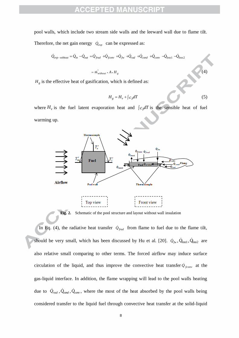
3.1. Flame behaviour of a pool fire
Fig. 4 and Fig. 5 show the typical flame images of a 10×10 cm pool fire with an
increase in airflow speeds and tilt angles without and with wall insulation, respectively.
In the quiescent condition, the flame shapes generally depend on the relative strength of
the buoyancy of the combustion products in drawing ambient air horizontally over the
pool’s base to participate in the combustion. As the airflow speeds increased, even by a
small amount, under the quiescent conditions (e.g., 0.49 m/s), the flame shapes were
distorted considerably, with the main part of the flame shifting to the downstream side,

11
which is because the buoyant force has not persisted in the flow for a long time, and the
horizontal air momentum dominates in the near field of the pool. In our experiments, the
fuel pan was only put on a support frame whose top was a 10×10 cm flat plate, and the
leeward edge of the fuel pan was aligned with the downstream edge of the flat plate.
It is found that with a tilt angle of 20° or 30°, the flame was tilted horizontally and
even downward, where the tip of the tilted flame was lower than the bottom of the pool at
high airflow speeds. This is a particular characteristic of the flame with the effect of
oblique airflow as shown in Fig. 4 and Fig. 5. It is also found that the turbulence intensity
and the volume of the flames with wall insulation weakened and reduced compared to
those without wall insulation. For the cases with pool wall insulation, the wrapping of the
flame around the fuel pan side rim was not obvious when the tilt angle was 0° and 10°,
but obvious for other cases.
Fig. 4. Flame images of pool fires under different airflow speeds and directions(L=10 cm, without pool wall insulation)
The detachment of the flames from the windward rim of the pools occurred at
relatively large air speeds and tilt angles, which was obvious at all tilt angles when the
airflow speed exceeded 1.74 m/s without wall insulation. In addition, the flame length
12
was also detected based on the flame images, which showed that the flame length first
increases and then decreases with increased airflow speeds. From these phenomenon, it
can be preliminary deduced that the fuel evaporation and fuel vapour diffusion rate from
the fuel surface decreased with wall insulation. Other explanations will be combined with
the measured mass loss and temperature data in the following sections.
Fig. 5. Flame images of pool fires under different airflow speeds and directions(L=10 cm, with pool wall insulation)
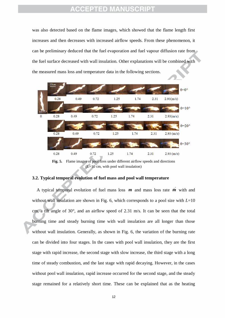
3.2. Typical temporal evolution of fuel mass and pool wall temperature
A typical temporal evolution of fuel mass loss m and mass loss rate &'m with and
without wall insulation are shown in Fig. 6, which corresponds to a pool size with L=10
cm, a tilt angle of 30°, and an airflow speed of 2.31 m/s. It can be seen that the total
burning time and steady burning time with wall insulation are all longer than those
without wall insulation. Generally, as shown in Fig. 6, the variation of the burning rate
can be divided into four stages. In the cases with pool wall insulation, they are the first
stage with rapid increase, the second stage with slow increase, the third stage with a long
time of steady combustion, and the last stage with rapid decaying. However, in the cases
without pool wall insulation, rapid increase occurred for the second stage, and the steady
stage remained for a relatively short time. These can be explained that as the heating

13
effect of the three rims of the pool by flame would decrease remarkably due to wall
insulation. However, in the cases without wall insulation, the pool wall will be heated
directly by the wrapping flame, which will enhance the fuel evaporation rate. Based on
the requirement of data analysis, only the steady burning stage was in a quasi-steady state
system. During this stage, the fuel liquid level will decrease with ongoing burning, but
the temperature readings were still steady at this stage in the current study for both of the
cases.
0 100 200 300 400 500 600
0
20
40
60
80
100without&'m
withoutmwithm
mas
s(g)
t(s)
with&'m
0.00
0.05
0.10
0.15
0.20
0.25
0.30
0.35
0.40
0.45
()
mas
sbu
rnin
gra
teg/
s
steady stage
Fig. 6. Typical temporal evolution of the mass loss and mass burning rate of pool fires with andwithout wall insulation (θ=30°, v=2.31 m/s, L=10 cm)
Figure 7 shows the typical temporal evolution of the wall temperature, which
corresponds to the cases in Fig. 6. In the steady burning stage, the wall temperature for
both cases basically remains a constant value. This will further account for the stability
of the mass burning rate at this stage.
In addition, it can be found that the windward rim temperature is lower than the other
rim temperature because the flame will be detached from the windward rim at an airflow
speed of approximately 2.31 m/s (as shown in Fig. 4 and Fig. 5), while the temperature of
the side and leeward rims are relative large due to the heating of the wrapping flame. In
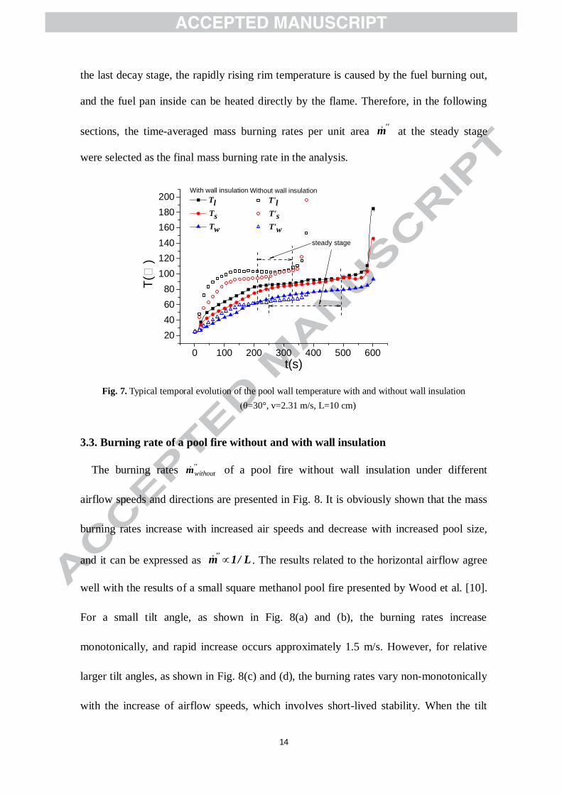
14
the last decay stage, the rapidly rising rim temperature is caused by the fuel burning out,
and the fuel pan inside can be heated directly by the flame. Therefore, in the following
sections, the time-averaged mass burning rates per unit area &''m at the steady stage
were selected as the final mass burning rate in the analysis.
0 100 200 300 400 500 600
20406080
100120140160180200
Without wall insulationT'lT'sT'w
T()
t(s)
With wall insulationTlTsTw
steady stage
Fig. 7. Typical temporal evolution of the pool wall temperature with and without wall insulation(θ=30°, v=2.31 m/s, L=10 cm)
3.3. Burning rate of a pool fire without and with wall insulation
The burning rates without&''m of a pool fire without wall insulation under different
airflow speeds and directions are presented in Fig. 8. It is obviously shown that the mass
burning rates increase with increased air speeds and decrease with increased pool size,
and it can be expressed as µ& ''m 1/ L . The results related to the horizontal airflow agree
well with the results of a small square methanol pool fire presented by Wood et al. [10].
For a small tilt angle, as shown in Fig. 8(a) and (b), the burning rates increase
monotonically, and rapid increase occurs approximately 1.5 m/s. However, for relative
larger tilt angles, as shown in Fig. 8(c) and (d), the burning rates vary non-monotonically
with the increase of airflow speeds, which involves short-lived stability. When the tilt

15
angle is relative large, the side and leeward rim of the pool will be heated by the tilt
flame, which cause initial sharp increases in the burning rate. The short-lived stability
may be caused by steady net energy gain from the flame and the surroundings of the
fuel.
0.0 0.5 1.0 1.5 2.0 2.5 3.010
20
30
40
50
m''(
g/m
-2s-1
)
v(m/s)
4cm 6cm 8cm 10cm
θ=0°
( )a
0.0 0.5 1.0 1.5 2.0 2.5 3.010
20
30
40
50
m''(
g/m
-2s-1
)
4cm 6cm 8cm 10cm
v(m/s)
θ=10°
( )b
0.0 0.5 1.0 1.5 2.0 2.5 3.0
10
20
30
40
50 θ=20°
v(m/s)
m''(
g/m
-2s-1
)
4cm 6cm 8cm 10cm
( )c
0.0 0.5 1.0 1.5 2.0 2.5 3.0
10
20
30
40
50 θ=30°
v(m/s)
m''(
g/m
-2s-1
)
4cm 6cm 8cm 10cm
( )d
Fig. 8. Burning rate of square pool fires without wall insulation for different airflow speeds and pool sizes
It is also found that as air speeds increase from 1.25 m/s to 1.74 m/s, the mass burning
rates increases rapidly at different wind directions and pool size. As shown in Fig. 4, the
flame detachment occurred at the air speed of 1.74 m/s, but it did not happen at the air
speed of 1.25 m/s. When the flame was detached, the turbulence of the flame was
obviously enhanced, and the convective heat transfer between the fuel and the flame at
the gas-liquid interface would be improved, therefore the combustion process would be
accelerated. When the air speed exceeds 1.74 m/s, the increase in the mass burning rates
is reduced. Overall, the various paths for heat transfer from the flame to the fuel lead to
evpQ&

16
the complex coupling effects on fuel evaporation and fuel combustion. The key point in
steady state is that the net rate of energy to the fuel by all of these mechanisms balances
the rate of energy consumed for fuel evaporation.

17
The burning rates with&''m of pool fires with wall insulation under different airflow
speeds and directions are presented in Fig. 9. Similar to Fig. 8, the burning rates decrease
with the increase of pool size, but the burning rates decrease obviously compared to the
cases without wall insulation. In addition, the differences in the burning rates with
different pool sizes are relatively small compared to the cases without wall insulation. In
which, the differences are relatively large when the airflow speeds exceed 1.5 m/s. For a
small tilt angle (θ=0° and θ=10°), as shown in Fig. 9(a) and (b), the burning rates with&''m
first decrease and then increase with increased air speeds, except for the cases of 4×4 cm
pool fires.
For small tilt angles and low air speeds, flame tilting would cause the view factor from
the flame to the fuel surface to decrease, which would reduce the radiative heat transfer
fradQ& . In addition, due to the small vertical components of the airflow speeds, the
convective heat transfer fconvQ& from the flame to the fuel is relative small. On the other
hand, due to wall insulation, the heating effect by flame wrapping is approximately
eliminated. Meanwhile, the flame is vertical in the quiescent condition, and the energy
from the flame to the fuel will be relatively large compared to the cases at low air speeds.
All of these lead to the first decrease in the burning rates. With the continued increase in
air speeds, the convective heat transfer will obviously increase, which will lead the
further increases in the burning rate.
fconvQ&

18
0.0 0.5 1.0 1.5 2.0 2.5 3.0
12
16
20
24
28m
″(gs
-1m
-2)
v(m/s)
4cm 6cm 8cm 10cm
θ=0°
( )a
0.0 0.5 1.0 1.5 2.0 2.5 3.0
12
16
20
24
28 θ=10°
m″(g
s-1m
-2)
4cm 6cm 8cm 10cm
v(m/s)
( )b
0.0 0.5 1.0 1.5 2.0 2.5 3.0
12
16
20
24
28 θ=20°4cm 6cm 8cm 10cm
m″(g
s-1m
-2 )
v(m/s)
( )c0.0 0.5 1.0 1.5 2.0 2.5 3.0
12
16
20
24
28 θ=30°
m″(g
s-1m
-2)
L=4cm L=6cm L=8cm L=10cm
v(m/s)
( )d
Fig. 9. Burning rate of square pool fires with wall insulation for different airflow speeds and pool sizes

19
When the tilt angle further increases up to 20° and 30°, the burning rates will
always increase with increased airflow speeds, except for the cases where the airflow
speeds are below 0.28 m/s. The understanding of this phenomenon is that the effects of
the oblique airflow on the flame shape and the fuel become more obvious due to the
increase in the vertical components of the airflow speeds. For instance, the convective
heat transfer was obviously enhanced compared to the one with small tilt angles
of airflow. For the cases with larger pool sizes, especially the 8×8 cm and 10×10 cm
pools, the lowest value of the burning rate occurred when the airflow speed was
approximately 0.28 m/s. The reasons are similar to the cases with small tilt angles, which
was discussed above.
However, for a small pool size of 4×4 cm with all of the tilt angles, the mass burning
rate increased with increased airflow speeds. It can be interpreted that the heat feedback
per unit area from the flame to the fuel is relatively large compared to the large pool size.
For all of the pool sizes, there is also a critical value of air speed leading to a relatively
fast increase in the burning rate, which corresponds to the flame detachment. In addition,
from Fig. 9, for all of the pool sizes and oblique airflow angles, a steady or very slow
state of increase in the mass burning rate with increased airflow speeds generally appears,
which can also be interpreted as the net rate of energy gain to the fuel by all of these
mechanisms and balances the rate of energy consumed for fuel evaporation.
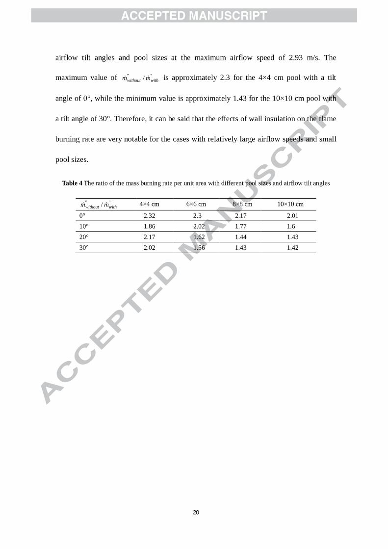
As shown in Table 4, a parameter /without withm m² ²& & is introduced to quantitatively indicate
the difference in the mass burning rate between the cases with and without wall
insulation. The values correspond to the ratio of the mass burning rates with different
with&''m
fconvQ&
20
airflow tilt angles and pool sizes at the maximum airflow speed of 2.93 m/s. The
maximum value of is approximately 2.3 for the 4×4 cm pool with a tilt
angle of 0°, while the minimum value is approximately 1.43 for the 10×10 cm pool with
a tilt angle of 30°. Therefore, it can be said that the effects of wall insulation on the flame
burning rate are very notable for the cases with relatively large airflow speeds and small
pool sizes.
Table 4 The ratio of the mass burning rate per unit area with different pool sizes and airflow tilt angles
4×4 cm 6×6 cm 8×8 cm 10×10 cm
0° 2.32 2.3 2.17 2.0110° 1.86 2.02 1.77 1.620° 2.17 1.62 1.44 1.4330° 2.02 1.56 1.43 1.42
/without withm m² ²& &
/without withm m² ²& &

21
3.4. Effects of airflow directions on mass burning rates
To indicate the influence of airflow directions on the burning rate of pool fire more
clearly, the burning rates with and without wall insulation for different airflow tilt angles
were plotted in Fig. 10 and Fig. 11. The data of burning rates for different pool sizes
under different tilt angles and airflow speeds are shown in Fig. 10. It can be seen that the
mass burning rates increase with increased tilt angles for all of the cases. However, the
differences in the mass burning rate with different tilt angles are relatively large in the
cases with wall insulation when airflow speed exceeds 1.5 m/s. In addition, the difference
of burning rate between the cases without and with wall insulation would decrease with
the increase of pool size. To describe the variation of HRR with ventilation velocity,
Carvel et al. [20] defined a coefficient, /vent natk Q Q= , where ventQ is the HRR with forced
ventilation and natQ is the HRR with natural ventilation. Similar to this, we define the mass
burning rate enhancement coefficient, k, as:
'' ''/tilted levelk m m= & & (11)
where ''tiltedm& is the mass burning rate with oblique airflow, ''
levelm& is the mass burning
rate with horizontal airflow.

22
0.0 0.5 1.0 1.5 2.0 2.5 3.010
20
30
40
50m
''(g/
m-2
s-1)
With wall insulation θ=0° θ=10° θ=20° θ=30°
Without wall insulation θ′=0° θ′=10° θ′=20° θ′=30°
v(m/s)
L=4cm
(a)
0.0 0.5 1.0 1.5 2.0 2.5 3.010
20
30
40
50
m''(
g/m
-2s-1
)
With wall insulation θ=0° θ=10° θ=20° θ=30°
Without wallinsulation θ′=0° θ′=10° θ′=20° θ′=30°
v(m/s)
L=6cm
(b)
0.0 0.5 1.0 1.5 2.0 2.5 3.010
20
30
40
50
m''(
gs-1m
-2)
With wall insulation θ=0° θ=10° θ=20° θ=30°
Without wall insulation θ′=0° θ′=10° θ′=20° θ′=30°
v(m/s)
L=8cm
(c)
0.0 0.5 1.0 1.5 2.0 2.5 3.010
20
30
40
50
m″(g
m2 s-
1 )
v(m/s)
With wall insulation θ=0° θ=10° θ=20° θ=30°
Without wall insulation θ′=0° θ′=10° θ′=20° θ′=30°
L=10cm
(d)
Fig. 10. Mass burning rate with and without wall insulation for different airflow speeds and directions
Fig. 11 and Fig. 12 show the results of k with and without wall insulation for different
airflow speeds and pool sizes, where withk and withoutk represent the data of the pool fire
with or without wall insulation, respectively. It can be seen that there are significant
differences in the effect of airflow directions on the mass burning rate between the two
cases. In addition, the values of k increase with an increase in the tilt angle for both cases.
For the cases without wall insulation, as shown in Fig. 11, the values of k first increase
until a peak value is reached and then decrease with an increase in airflow speed.
Combined with Fig. 10, it can be concluded that the effect of the airflow direction on the
mass burning rate is only prominent at relatively lower airflow speeds (e.g., 0.49-1.25
m/s). As shown in Fig. 4, at this range of airflow speeds, the variation of flame shape is
obvious with the increased airflow tilt angle. For instance, with an air speed of 0.72 m/s,
the flame tilt gradually increased with the airflow tilt angle increasing from 0° to 30°. At
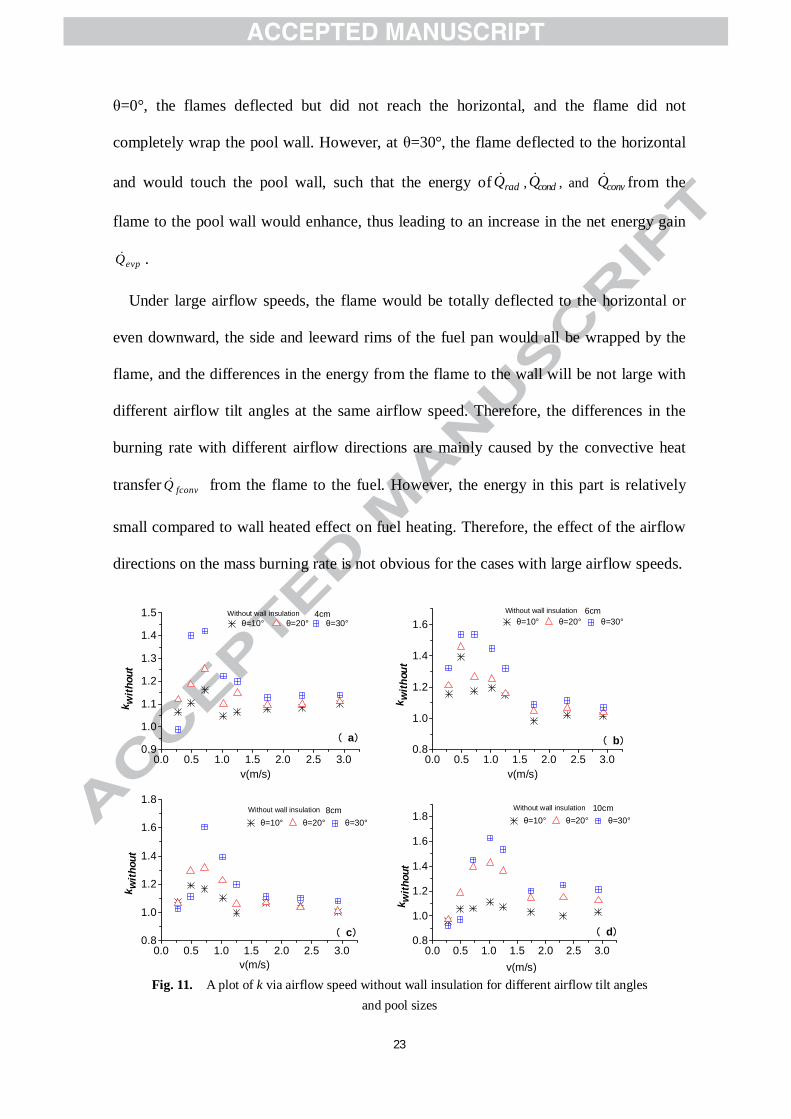
23
θ=0°, the flames deflected but did not reach the horizontal, and the flame did not
completely wrap the pool wall. However, at θ=30°, the flame deflected to the horizontal
and would touch the pool wall, such that the energy of radQ& , condQ& , and convQ& from the
flame to the pool wall would enhance, thus leading to an increase in the net energy gain
evpQ& .
Under large airflow speeds, the flame would be totally deflected to the horizontal or
even downward, the side and leeward rims of the fuel pan would all be wrapped by the
flame, and the differences in the energy from the flame to the wall will be not large with
different airflow tilt angles at the same airflow speed. Therefore, the differences in the
burning rate with different airflow directions are mainly caused by the convective heat
transfer fconvQ& from the flame to the fuel. However, the energy in this part is relatively
small compared to wall heated effect on fuel heating. Therefore, the effect of the airflow
directions on the mass burning rate is not obvious for the cases with large airflow speeds.
0.0 0.5 1.0 1.5 2.0 2.5 3.00.9
1.0
1.1
1.2
1.3
1.4
1.5 Without wall insulation
k with
out
v(m/s)
θ=10° θ=20° θ=30°4cm
( )a
0.0 0.5 1.0 1.5 2.0 2.5 3.00.8
1.0
1.2
1.4
1.6
k with
out
v(m/s)
θ=10° θ=20° θ=30°6cmWithout wall insulation
( )b
0.0 0.5 1.0 1.5 2.0 2.5 3.00.8
1.0
1.2
1.4
1.6
1.8
k with
out
v(m/s)
θ=10° θ=20° θ=30°8cmWithout wall insulation
( )c0.0 0.5 1.0 1.5 2.0 2.5 3.0
0.8
1.0
1.2
1.4
1.6
1.8
k with
out
v(m/s)
θ=10° θ=20° θ=30°10cmWithout wall insulation
( )d
Fig. 11. A plot of k via airflow speed without wall insulation for different airflow tilt anglesand pool sizes

24
0.0 0.5 1.0 1.5 2.0 2.5 3.0v(m/s)
θ=10° θ=20° θ=30°4cmWith wall insulation
( )a0.9
1.0
1.1
1.2
1.3
1.4
1.5k w
ith
0.0 0.5 1.0 1.5 2.0 2.5 3.00.8
1.0
1.2
1.4
1.6
k with
v(m/s)
θ=10° θ=20° θ=30°6cmWith wall insulation
( )b
0.0 0.5 1.0 1.5 2.0 2.5 3.00.8
1.0
1.2
1.4
1.6
1.8
k wit
h
v(m/s)
θ=10° θ=20° θ=30°
8cmWith wall insulation
( )c
0.0 0.5 1.0 1.5 2.0 2.5 3.00.8
1.0
1.2
1.4
1.6
1.8
k wit
h
v(m/s)
θ=10° θ=20° θ=30°
( )d
10cmWith wall insulation
Fig. 12. A plot of k via airflow speed with wall insulation for different airflow tilt anglesand pool sizes
For the cases with wall insulation, as shown in Fig. 12, the values of k first increase
and then remain steady at a certain value with an increase in airflow speeds. Due to the
insulation of the pool wall, the effect of the wall heating will not exist. The effects of the
oblique airflow on the convective heat transfer fconvQ& from the flame to the fuel would
be the main part that would lead to the change in the burning rates with different airflow
tilt angles. Therefore, the differences in the burning rates with different tilt angles are
relatively large with wall insulation, compared to that without wall insulation under large
airflow speeds.
4. Conclusions
The effects of oblique airflow on the burning rate of square ethanol pool fires with and
without wall insulation have been studied experimentally based on a small-scale wind
tunnel. The variation in the fuel mass loss and wall temperature were measured to
25
analyse the effect of wall insulation and oblique airflow on the pool fire burning rates.
The following conclusions can be drawn:
(1) The mass burning rates are obviously reduced due to the insulation of the pool wall,
especially in the cases with larger airflow speeds.
(2) The mass burning rates decrease with increased pool size. However, in the cases
with wall insulation, the differences in the mass burning rates are relatively small, while
for the cases without wall insulation, the differences are relatively large, especially when
the airflow speeds exceed 1.5 m/s.
(3) The burning rates increase with increased airflow tilt angles for both cases with or
without wall insulation. However, in the cases with wall insulation, the change in the
mass burning rates with different airflow tilt angles are relatively large when the airflow
speed exceeds 1.5 m/s.
Acknowledgments
The authors appreciate the support of the China National Key Basic Research Special
Funds Project (Grant No. 2012CB719704) and the Natural Science Foundation of China
(Grant No. 51323010).
References
[1] Nasr A, Suard S, El-Rabii H, Garo JP, Gay L, Rigollet L, Heat feedback to the fuel
surface of a pool fire in an enclosure, FireSafetyJ. 60(2013)56-63.
DOI: 10.1016/j.firesaf.2012.12.005
[2] Alireza V, David SN, Larry WK,Effects of altering the liquid phase boundary
conditions of methanol pool fires,Exp. Therm.Fluid Sci. 44 (2013) 786–791.
DOI: 10.1016/j.expthermflusci.2012.09.023
[3] Philippe Dagaut, Abderrahman El Bakali, Alain Ristoridoi, The combustion of
kerosene: Experimental results and kinetic modelling using 1- to 3-component

26
surrogate model fuels, Fuel 85(2006)944-956. DOI:10.1016/j.fuel.2005.10.008
[4] Benjamin DD, John L, Thomas KB, Marcos C, Robert GBJ, Sergey BD, Pool
fires-An empirical correlation. Combust. Flame160(2013)2964-2974.
DOI: 10.1016/j.combustflame.2013.06.020
[5] Novozhilov V, Koseki H, CFD prediction of pool fire burning rates and flame
feedback. Combust. Sci. Technol. 176(2004)1283-1307.
DOI: 10.1080/00102200490457484
[6] Sudheer S, Prabhu SV, Measurement of flame emissivity of gasoline pool
fires,Nucl.Eng. Des. 240 (2010) 3474–3480.DOI: 10.1016/j.nucengdes.2010.04.043
[7]Chen B, Lu SX, Li CH, Kang QS, Lecoustre V. Initial fuel temperature effects on
burning rate of pool fire. J. Hazard. Mater. 188(2011)369-74.
DOI: 10.1016/j.jhazmat.2011.01.122
[8] Chatris JM, Quintela J, Folch J, Planas E, Arnaldos J, Casal J, Experimental study of
burning rate in hydrocarbon pool fires. Combust. Flame 126(2001)1373-1383.
DOI: 10.1016/S0010-2180(01)00262-0
[9] Woods JAR, Fleck BA, Kostiuk LW, Effects of transverse air flow on burning rates of
rectangular methanol pool fires, Combust. Flame 146(2006)379-390.
DOI: 10.1016/j.combustflame.2006.02.007
[10] Roh JS, Ryou HS, Kim DH, Jung WS, Jang YJ, Critical velocity and burning rate in
pool fire during longitudinal ventilation, Tunn. Undergr. Sp. Technol. 22(2007)
262-271.DOI: 10.1016/j.tust.2006.08.003
[11] Roh JS, Yang SS, Ryou HS, Tunnel fires: experiments on critical velocity and
burning rate in pool fire during longitudinal ventilation, Journal Fire Sciences 2007;
25: 161-176.DOI: 10.1177/0734904107067300
[12] Roh JS, Yang SS, Ryou HS, Yoon MO, Jeong YT, An experimental study on the
effect of ventilation velocity on burning rate in tunnel fires-heptane pool fire case,
Build. Environ. 43(2008) 1225-1231.DOI:10.1016/j.buildenv.2007.03.007
[13] Boboulos M, Purvis MRI, Wind and slope effects on ROS during the fire
propagation in East-Mediterranean pine forest litter, Fire Safety J. 44(2009)
764-69.DOI: 10.1016/j.firesaf.2009.03.006

27
[14] Perez Y, Pastor E, Agueda A, Planas E, Effect of wind and slope when scaling the
forest fires rate of spread of laboratory experiments. Fire Technol.
47(2011)475-89.DOI: 10.1007/s10694-010-0168-7
[15] Tao CF, Wang XS, Zhang XN, Effects of transverse air flow on mass loss rate of
alcohol pool fires in an inclined wind tunnel, J. Civ. Eng. Manag. 2014 (In press).
[16] Tao CF, He YP, Li Y, Wang XS, Effects of oblique air flow on burning rates of
square ethanol pool fires, J. Hazard. Mater. 260(2013) 552-562.
DOI: 10.1016/j.jhazmat.2013.06.015
[17] Chou HM, Wong KL, Heat transfer characteristics of an insulated regular polygonal
pipe by using a wedge thermal resistance model, Energ. Convers. Manage. 44(2003)
629-645. DOI: 10.1016/S0196-8904(02)00064-X
[18] Wong KL, Chou HM, Li YH, Complete heat transfer solutions of an insulated
regular polygonal pipe by using a PWTR model, Energ. Convers. Manage.
45(2004)1705-1724. DOI: 10.1016/j.enconman.2003.09.025
[19] Carvel RO, Beard AN, Jowitt PW, Drysdale DD, Variation of heat release rate with
forced longitudinal ventilation for vehicle fires in tunnels, Fire Safety J.
36(2001)569-96.DOI: 10.1016/S0379-7112(01)00010-8
[20] Hu LH, Liu S, Wu L, Flame radiation feedback to fuel surface in medium ethanol
and heptane pool fires with cross air flow, Combust. Flame 160 (2013) 295–306.
DOI: 10.1016/j. combust flame.2012.10.016

28
Highlights
l Turbulence and volume of the flame reduce significantly as pool wall is
insulated.
l The mass burning rates obviously decrease as the pool wall is
insulated.
l The reduction of mass burning rate is sensitive to pool size and airflow
speeds.
l Mass burning rate with wall insulation is less sensitive to pool size as
v>1.5 m/s.
l Mass burning rate are quite different under different airflow directions.