Calcium Silicate Insulation Board Manufacturing Business ...
Upload
khangminh22Category
view
0download
0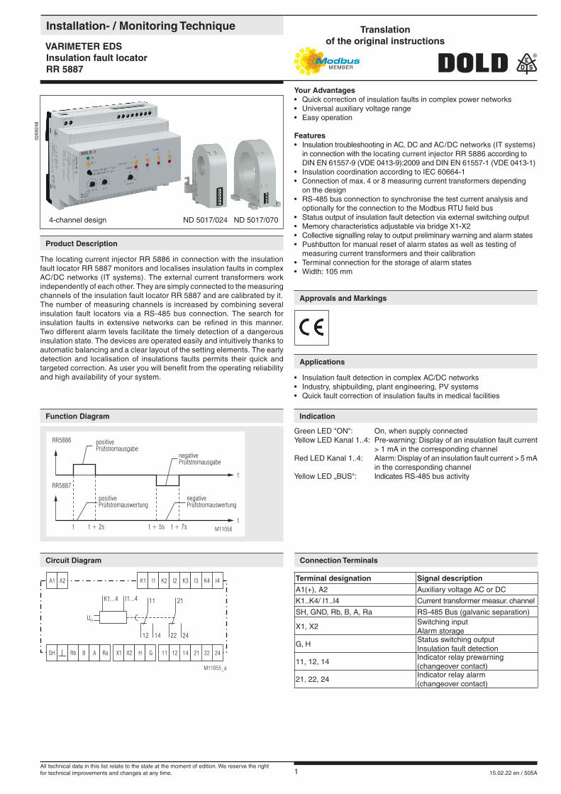
1 15.02.22 en / 505A
0269
248
The locating current injector RR 5886 in connection with the insulation fault locator RR 5887 monitors and localises insulation faults in complex AC/DC networks (IT systems). The external current transformers work independently of each other. They are simply connected to the measuring channels of the insulation fault locator RR 5887 and are calibrated by it.The number of measuring channels is increased by combining several insulation fault locators via a RS-485 bus connection. The search for insulation faults in extensive networks can be refined in this manner. Two different alarm levels facilitate the timely detection of a dangerous insulation state. The devices are operated easily and intuitively thanks to automatic balancing and a clear layout of the setting elements. The early detection and localisation of insulations faults permits their quick and targeted correction. As user you will benefit from the operating reliability and high availability of your system.
positivePrüfstromauswertung
negativePrüfstromauswertung
negativePrüfstromausgabe
positivePrüfstromausgabe
M11056
RR5886
RR5887
t t + 2s t + 5s t + 7s
t
t
Your Advantages• Quick correction of insulation faults in complex power networks• Universal auxiliary voltage range• Easy operation
Features• Insulation troubleshooting in AC, DC and AC/DC networks (IT systems) in connection with the locating current injector RR 5886 according to DIN EN 61557-9 (VDE 0413-9):2009 and DIN EN 61557-1 (VDE 0413-1)• Insulation coordination according to IEC 60664-1• Connection of max. 4 or 8 measuring current transformers depending on the design• RS-485 bus connection to synchronise the test current analysis and optionally for the connection to the Modbus RTU field bus• Status output of insulation fault detection via external switching output• Memory characteristics adjustable via bridge X1-X2• Collective signalling relay to output preliminary warning and alarm states• Pushbutton for manual reset of alarm states as well as testing of measuring current transformers and their calibration• Terminal connection for the storage of alarm states• Width: 105 mm
Green LED "ON": On, when supply connectedYellow LED Kanal 1..4: Pre-warning: Display of an insulation fault current > 1 mA in the corresponding channel Red LED Kanal 1..4: Alarm: Display of an insulation fault current > 5 mA in the corresponding channel Yellow LED „BUS“: Indicates RS-485 bus activity
• Insulation fault detection in complex AC/DC networks• Industry, shipbuilding, plant engineering, PV systems• Quick fault correction of insulation faults in medical facilities
Installation- / Monitoring Technique
VARIMETER EDSInsulation fault locatorRR 5887
Product Description
Function Diagram
Approvals and Markings
Circuit Diagram Connection Terminals
Terminal designation Signal descriptionA1(+), A2 Auxiliary voltage AC or DC
K1..K4/ I1..I4 Current transformer measur. channel
SH, GND, Rb, B, A, Ra RS-485 Bus (galvanic separation)
X1, X2Switching input Alarm storage
G, HStatus switching output Insulation fault detection
11, 12, 14Indicator relay prewarning (changeover contact)
21, 22, 24Indicator relay alarm (changeover contact)
Applications
Indication
Rb 14X1SH 11B 21X2 12A 22HRa 24G
K3 K4K1 K2A1 I3 I4I1 I2A2
M11055_a
K1...4
UH
I1...4 11 21
12 2214 24
4-channel design ND 5017/024 ND 5017/070
Translationof the original instructions
All technical data in this list relate to the state at the moment of edition. We reserve the rightfor technical improvements and changes at any time.
2 15.02.22 en / 505A
Switching inputThe device is equipped with a switching input (terminals X1, X2), which can be furnished either with a simple wire bridge or selected actively as digital control input from an external device with max. 24 V DC.
The input is low-active, i. e. when applying a low-level, the function "ALARM MEMORY" is active, otherwise it is inactive.
If the function is active, no prewarning/alarm states are reset following an insulation fault locating cycle. A reset takes place only after pushing the "Alarm reset / Test / Transformer calibration" button for at least 3 sec. Only the prewarning / alarm states are stored. The residual current values transmitted via Modbus are always up-to-date.
X1X2
ALARM MEMORY active- Alarm states are preserved - Manually resettable via pushbutton
X1X2
ALARM MEMORY inactive- Alarm states are updated after each measuring cycle
Switching outputThe device is equipped with a transistor switching output (terminals G, H), which is protected by a series-connected PTC (RN = 220 Ω).
In the idle state (no insulation fault detection active), the output is high-resistance. During insulation fault detection, the output is low-resistance (RN) and delivers a low-level in conjunction with a series pull-up resistor and an external voltage source.
RS-485 bus connectionThe insulation fault locator RR 5887 generally works in slave mode.It synchronises itself independently with the test current output by monitoring the RS485 telegram. All connected insulation fault locators RR 5887 work in parallel and independently from each other.
If the insulation fault location system is part of a Modbus RTU field bus system for every device a free bus address has to be selected via a 10-step rotary switch. In case of need a Modbus Master can read out insulation fault current values from the connected devices with a resolution of 0,5 mA.
If there is no external bus connection, the bus address has no special meaning and the position of the rotary switch is arbitrary. The rotary swit-ches for baudrate selection of all RR 5886 and RR 5887 devices have to be identical independent of the bus operation mode. The prefered baudrate is 9600 Baud (rotary switch position 4).
Notes
Influence of discharge capacitiesThe insulation fault locator is also able to perform reliable measurements under the influence of discharge capacities up to a certain size. The influence of discharge capacities depends on the insulation resistance and the mains voltage. Reliable detection of insulation resistance is ensured up to a discharge capacity of 1 µF.The lower the mains voltage, the greater the permissible discharge capacity may be. For example, with mains voltages of 50 V, 20µF and more can also be processed without problem.
Insulation fault detection is no longer possible if the influence of the discharge capacities becomes too great. The measuring result may become poorer, in addition, when the discharge capacities are distributed unevenly in the network.However, the symmetry relationships of the insulation fault resistances themselves do not affect the quality of the measurement.Attention:If insulation faults are present between several conductors and PE, mains compensation currents flow through the insulation fault resistances overlaying the actual insulation fault currents. The measured insulation fault current can be reduced by half here in the extreme case.
If several insulation faults occur simultaneously in a network, the test current is divided among the individual fault branches. Depending on the fault resistance, it may happen that the maximum test current is not sufficient to address all detectors. To prevent such insulation faults from remaining undetected, it is recommended to position a current transformer in the main branch of the monitored network, which reliably detects the overall insulation fault (see connection diagram page 9).
Common operation of insulation monitor and insulation fault location systemInsulation monitoring and insulation fault location are often used in addition (s. connection example). As a rule, an insulation monitor detects an insulation fault and then controls an insulation fault location system that locates the fault. During localization, the insulation monitor should temporarily stop his monitoring activity in order to avoid mutual interference between the insulationmonitoring device and the localization system.
Current transformer calibrationCurrent transformer calibration is performed after switching on the device or after pushing the "Alarm reset/ Test/ Transformer calibration" pushbutton to compensate tolerances of the magnetic material of the current transformers and the resulting differences of the magnetic amplification.
Insulation fault measurement in AC/DC networksIf an alternating current network, containing a downstream rectifier, is monitored, insulation fault detection can also be performed in the direct voltage circuit if the discharge capacities in this circuit are not too high.Because fault detection can be performed simultaneously in two different network forms – alternating current network and direct current network – the indications displayed for prewarning and alarm are quantitatively valid only for the network form set with the rotary switch. The network form not set will deliver results deviating by the factor 2. However, they can still be analysed in terms of their tendency, i. e. a potential insulation fault is still indicate.
Insulation fault current displayThe locating current injector takes the power for the test current from the monitored network itself. Insulation fault current measurements are nearly identical both for AC and DC networks. However, a difference in the level of the test current is obtained through the network form itself. With AC networks, the test current is only half the value as with DC networks.With 3AC networks, the factor is 0.67. These differences are taken into account when determining the level of the insulation fault current and with the display of the alarm values.
Function
3 15.02.22 en / 505A
Indication of alarm statesThe display of an alarm state as well as the response of the corresponding common alarm signalling relay act at least for the duration of a measuring cycle (12 sec). The alarm state is cancelled again when the respective threshold of the insulation fault current, under consideration of a defined hysteresis, is fallen below again.
The switching terminal "ALARM MEMORY" must be equipped if the alarm state shall persist permanently.
The response threshold for the insulation fault current does not depend on the network form chosen.
Prewarning
Response threshold: 1 mAIndication: Yellow LED continuously onCommon alarm relay: Collective signalling relay "Prewarning" respondsHysteresis for return: 0.1 mADuration of the alarm state: Until response threshold if fallen below
Alarm
Response threshold: 5 mAIndication: Rote LED leuchtet dauer-rotCommon alarm relay: Collective signalling relay "Alarm" respondsHysteresis for return: 0.5 mADuration of the alarm state: Until response threshold if fallen below
No insulation faults present
Indication: The yellow LED briefly (200 ms) lights after the measuring cycle has been completed
Display of current transformer faultsThe insulation fault locator does not feature any control elements for setting the completion of current transformers. For this reason, the device must detect the presence of transformers independently. This happens together with the transformer calibration after switching on the device or after pushing the "Alarm Rest/ Test/ Transformer calibration" button.
The device can detect both, a transformer short circuit and a broken supply line (open transformer contact) individually for each channel.
The check for transformer faults is cyclically repeated after an insulation fault measurement has been completed allowing a transformer fault to be detected also under ongoing operation.
Short circuit at current transformer
Indication: Red LED flashesDuration of indication: Until the short circuit is resolved
Indication detected/interrupted measuring current transformer
Indication: Yellow LED flashesDuration of indication: Until current transformer test is completed or open current transformer connection is closed again
Indication of invalid insulation fault measurements
If the value determined for the insulation fault current is invalid, e.g. be-cause of excessive discharge capacities, or the direction of line routing through the current transformer is wrong, this condition is also indicated.
Indication: Yellow LED flashesDuration of indication: Until a valid measured value is determined again or the line direction through the transformer was turned around
Indication of alarm and functional states
Function-Codes
At RR 5887 the following function codes are implemented:
Function-Code
Name Description
0x04 Read Input Register Device state / read current transformer state and insulation fault currents
Adress- / Baud rate setting
Pos. Potentiom.ADR 10x
0 1 2 3 4 5 6 7 8 9
Adress Modbus RTU
100 101 102 103 104 105 106 107 108 109
Pos. Potentiom.BAUD
1 2 3 4 5 6 7 8
Baud rateBaud
1200 2400 4800 9600 19200 38400 57600 115200
The device address and baudrate are only read once after application of the auxiliary voltage.
For communication between motor controller and a supervising control the Modbus RTU protocol according to Specification V 1.1b3 is used.
Modbus RTU
Bus Interface
Protocol Modbus Seriell RTUAdress 100 bis 109Baud rate 1200, 2400, 4800, 9600, 19200, 38400, 57600, 115200 BaudData bit 8Stop bit 2Parity None
More information about the interface, wiring rules, device identification and communication monitoring can be found in the Modbus user manual.
4 15.02.22 en / 505A
Auxiliary voltage
Measured nominal voltage UB: AC/DC 24 ... 80 V; AC/DC 85 ... 230 VOperating voltage Ue: AC/DC 21 ... 88 V; AC 77 ... 265 V, DC 77 ... 290 VFrequency range: DC or AC 45 ... 400 HzNominal consumption: DC max. 3 W AC max. 3.5 VA
Monitored network
Operating voltage UB: DC / AC / 3AC 21 ... 500 VMeasured nominal voltage Ue: DC / AC / 3AC 24 ... 455 VFrequency range: AC/ 3AC 40 ... 60 HzRated current range forinsulation test currents: 1 ... 5 mAMaximum test current output: 6.5 mAResponse sensitivity: 0.4 mAResponse time: 15 sMeasuring accuracy: ± 10%Bus (galvanic separation): RS-485
Measuring current transformer
Terminals: K1, I1 … K4, I4Measuring current transformer: ND 5017Burden: 180 ΩRated voltage: 500 VRated frequency: 40 … 60 HzResponse sensitivity: 0.2 mAMeasuring range: 0.5 … 10 mANumber of measuring channel: 4
Switching input
Terminals: X1, X2Configuration (passive)Low-level: Bridge set / input low resistance High-level: Input open / input high-resistanceConfiguration (active)Voltage range (low/high): 0V / 12 ... 24 VMax. switching current (24 V): 0.5 mA
Switching output
Terminals: H(+), G(-)Switching output (passive): Transistor outputsInsulat. fault detection active: Output low resistance (minimal 220 Ω via PTC) Insulat. fault detection inactive: Output high resistanceSwitching voltage max.: 24 VSwitching current max. (24 V): 10 mA
RS-485 Bus
Terminals: SH, ⊥, Rb, B, A, RaBus: Galvanic separationTransmission medium: Twisted, shielded two-wire line (SH)Network termination: Bus termination via bridges Rb, B and Ra, A
Technical Data
Summary: Indication of alarm- and function states
Operation State oftransducer
Insulation failure current Ifs
Indication
Measuringoperartion
Transducer connectionok
Prewarning:Ifs > 1 mA
Yellow LEDcontinuously on
Alarm:Ifs > 5 mA
Red LEDcontinuously on
NoInsulation failure: Ifs < 1 mA
Yellow LEDBriefly lights at the end of the measuring cycle
Measurement value invalid
Yellow LEDflashes
Short circuit attransducer
Red LEDflashes
Breaking attransducer
Yellow LEDflashes
Transducer not connected
No indication
TransducerTest/ calib-ration
Transducershort circuit
Red LEDflashes
Transducerdetected
Yellow LEDflashes
Indication of alarm- and function states

5 15.02.22 en / 505A
Connection alarm signalling relay Output: 2 changeover contactsContact material: AgNi + 0.3 µm AuMeasured nominal voltage: AC/DC 24 … 240 VLimiting continuous current(Ith max): 2 x 5 ASwitching capacityTo AC 15NO contact: 3 A / AC 230V IEC/EN 60947-5-1NC contact: 1 A / AC 230V IEC/EN 60947-5-1Elektrical lifeTo AC 15At 3 A, AC 230V: 2 x 10⁵ switching cycl. IEC/EN 60947-5-1Short circuit strengthMax. fuse rating: 6 A gG / gL IEC/EN 60947-5-1Mechanical life: > 20 x 106 switching cycles
Terminal designation relay:
Prewarning: Alarm:
M11062
11 21
12 2214 24
General Data Nominal operating mode: Continuous operationTemperature range:Operation: - 20 ... + 60 °CStorage: - 25 ... + 60 °CRelative air humidity: 93% at 40 °CAltitude: ≤ 2000 mClearance and creepage distance Rated impulse voltage/pollution degree: 4 kV / 2 IEC 60664-1EMCElectro static discharge (ESD): 8 kV (air) IEC/EN 61000-4-2HF irradiation 80 MHz ... 2,7 GHz: 10 V / m IEC/EN 61000-4-3Fast transients: 2 kV IEC/EN 61000-4-4Surge voltageBetween wires for power supply: 2 kV IEC/EN 61000-4-5 Between wire and ground: 4 kV IEC/EN 61000-4-5HF-wire guided: 10 V IEC/EN 61000-4-6Interference suppression: Limit value class B EN 55011Degree of protectionHousing: IP 40 IEC/EN 60529Terminals: IP 20 IEC/EN 60529Housing: Thermoplastic with VO behaviour acc. to UL subject 94Vibration resistance: Amplitude 0.35 mm Frequenz 10...55 Hz, IEC/EN 60068-2-6Climate resistance: 20 / 060 / 04Terminal designation: EN 50005Wire connection DIN 46228-1/-2/-3/-4Fixed screw terminalsCross section: 0.2 ... 1.5 mm² (AWG 24 - 16) solid or 0.2 ... 1.5 mm² (AWG 24 - 16) stranded wire with ferrulesStripping length: 7 mmFixing torque: 0.4 NmMounting: DIN-rail IEC/EN 60715Weight: Approx. 225 g
Dimensions Width x height x depth: 105 x 90 x 71 mm
Technical Data
RR 5887.12 AC/DC 85 ... 265 VArticle number: 0068221• Auxiliary voltage: AC/DC 85 ... 230 V• Rated current for insul. test: 5 mA• Maximum test current output: 6.5 mA• Response sensitivity: 0.4 mA• Prewarning Hysteresis: 0.1 mA): 1.0 mA• Alarm (Hysteresis: 0.5 mA): 5.0 mA• Width: 105 mm
Standard Type
Ordering example
RR 5887 .12 / 0 _ _ AC/DC 85 ... 230 V
Auxiliary voltage Number of measuring channels: 0: 4-channel 1: 8-channel
0: Industrial plants 1: Rooms for medical purposes
Contacts Type
RR 5887.12/010 AC/DC 85 ... 265 VArticle number: 0067691• Auxiliary voltage: AC/DC 85 ... 230 V• Rated current for insul. test: 1.0 mA• Maximum test current output: 1.0 mA• Response sensitivity: 0.3 mA• Prewarning Hysteresis: 0.1 mA): 0.5 mA• Alarm (Hysteresis: 0.1 mA): 1.0 mA• Width: 105 mm
Variant

6 15.02.22 en / 505A
Parameter table
Every slave owns an output- configuration- and actual value table. In these tables it is defined under which address the parameters can be found.
Input Register (Device state / prozes data):
Register-Adress
Protocol- Adresse
Name Value range Description Data type Access rights
30001 0StateInsulation fault detection
0 … 1
0: Insulation fault detect. inactive1: Insulation fault detect. done/ insulation fault currents valid
UINT16 Read
30002 1 No. of channels 4 … 80x0004: 4-channel variant0x0008: 8-channel variant
UINT16 Read
30003 2 Max. insulation fault 1 … 5 Max. insul. fault in mA UINT16 Read
30004 3 Network form 0 … 20x0000: DC0x0001: AC0x0002: 3AC
UINT16 Read
30005 …
30008
0x0004 … 0x0007
State Current transformer1 … 4
0x0000 … 0x20FF
MSB:0x00: Transformer not connected0x01: Transformer connected0x02: Prewarning0x04: Alarm0x10: Short circuit0x20: State of transform. unknown/faultyLSB:Insul. fault current x 0.1 mA(0xFF: invalid meas. value)
UINT16 Read
30009 …
30012
0x0008 … 0x000B
State Current transformer5 … 8
0x0000 … 0x20FF
MSB:0x00: Transformer not connected0x01: Transformer connected0x02: Prewarning0x04: Alarm0x10: Short circuit0x20: State of transform. unknown/faultyLSB:Insul. fault current x 0.1 mA(0xFF: invalid meas. value)
UINT16 Read
30013 0x000C Alarm memory0x0000...0xFFFF
MSB:
Bit 7 ... 0 *)
Alarm occured in currenttransformator 8 ... 1LSB:Bit 7 ... 0prewarning occured in current transformer 8 ... 1
UINT16 Read
*) The stored alarm states remain until reset by the alarm push button.

7 15.02.22 en / 505A
• Insulation fault detection in AC / DC / 3AC IT networks in connection with the locating current injector RR 5886• External selection via an insulation monitoring device possible
System overview
Connection to measuring bus /Profibus gateway
Sequence Diagram Modbus Control Insulation Fault Location Modbus Control Insulation Fault Detection Telegram Examples
Request test current output: 6Xh, 02h, 00h, 00h, 00h, 01h, XXh, XXh
Read insulation fault currents: (4-channel): 6Xh, 04h, 00h, 04h, 00h, 04h, XXh, XXh
Read insulation fault currents: (8-channel): 6Xh, 04h, 00h, 04h, 00h, 08h, XXh, XXh
M11931
Modbus
MasterRR5886
Locating currentoutput
Insulation faultlocation
Request locating current output
Locating current output startet
Output insulation fault currents
Read insulation fault currents
RR5887
Sequence diagram Modbus control insulation lault loacation
RR5887/1
ProfibusSlave
1
RR5886
ProfibusMaster
RR5887/n
ProfibusSlave
n
ProfibusSlave
ModbusMaster
M11983
Insulationmonitor
M12269
RR5886
RR5887/1 RR5887/2
RS-485
Insulationmonitor
M12272
RR5886
RR5887/1 RR5887/2
ModbusMaster
RS-485
Insulation fault without external Modbus-Master (stand-alone system) Insulation fault with external Modbus-Master
Example for Modbus setting:
Device Adress-Potentiometer
Potentiometerposition
Modbus Adress
RR 5886 ADR 101 – 109 Master -
RR 5887/1 ADR 100 – 109 0 (optional) -
RR 5887/2 ADR 100 – 109 0 (optional) -
… ADR 100 – 109 0 (optional) -
Example for Modbus setting:
Device Adress-Potentiometer
Potentiometerposition
Modbus Adress
RR 5886 ADR 101 – 109 1 101
RR 5887/1 ADR 100 – 109 0 100
RR 5887/2 ADR 100 – 109 2 102
… ADR 100 – 109 … …

8 15.02.22 en / 505A
Measuring current transformer ND 5017/024
• The Measuring current transformer ND 5017/024 is designed for DIN rail mounting or screw-type mounting • Mounting on the top-hat rail may be done horizontally or vertically
Technical Data Rated voltage: 500 VRated nominal voltage: 1 ARated transformation ratio: 1 : 3000Burden: 180 ΩRated frequency: 40 … 65 HzTemperature range: -20 ... + 60 °CRated impulse voltage/pollution degree: 4 kV / 3Housing: Thermoplastic with VO behaviour acc. to UL subject 94Vibration resistance: Amplitude 0.35 mm frequency 10...55 Hz, IEC/EN 60068-2-6Climate resistance: 20 / 060 / 04Wire connectionSingle wire≥ 0.75 mm² : Up to 1 m≥ 0.75 mm² twisted: Up to 10 mCable shield ≥ 0.5 mm² : Up to 25 m (Shield on one side on I-conductor and not to be earthed)DIN rail mounting: Integrated clips for vertical and horizontal mountingScrew fixing: M3 or M4Fixing torque: Max. 0.8 NmWeight: 97 g
Dimensions Width x height x depth: 105 x 90 x 71 mm
M11349
24
41,3
45,5
4,2
24
5
75
4
25
for DIN rail mounting or screw mounting
M10979_b
B
EF
k
D
H
L1
L
C
ND 5017/070 øD L H H1 B C F k E GDimensions/mm 70 111 110 115 32 37 55 4,2 50* 74*Weight / g approx. 220*) Drill tolerance for screw mounting: ± 0.5 mm
Measuring current transformer ND 5017/070 (on request)
Accessories
High forces when mounting may damage the current transformer fixtures.The fixing clips are designed to support the current transformer. Forces that are applied by the cable running through the current transformer can only be tolerated within limitations. During installation and afterwards please make sure that the wires are led through the current transformer without applying pressure and remain stable in that position.
Mounting instructions for screw mounting
9 15.02.22 en / 505A
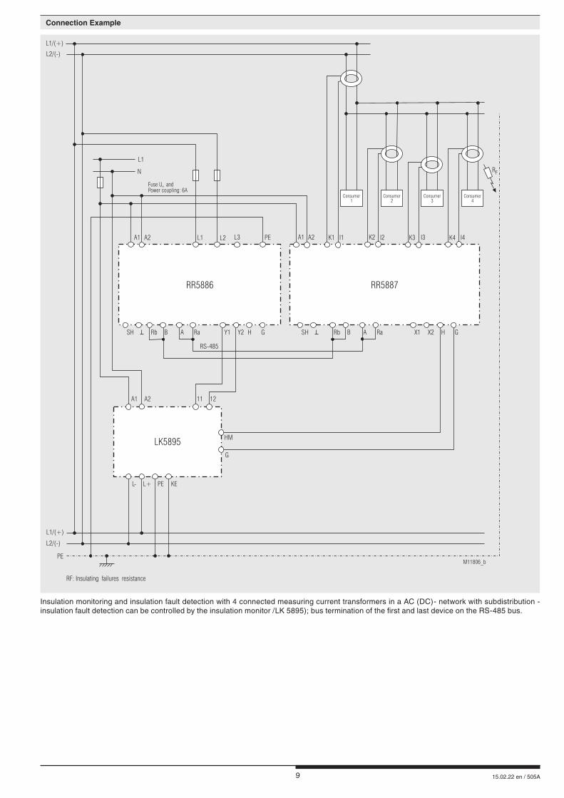
Insulation monitoring and insulation fault detection with 4 connected measuring current transformers in a AC (DC)- network with subdistribution - insulation fault detection can be controlled by the insulation monitor /LK 5895); bus termination of the first and last device on the RS-485 bus.
Connection Example
PE
L1
L1/(+)
N
Fuse U andPower coupling: 6A
H
L2/(-)
RbSHSH Rb BB A HH
PE KE
HM
X1Y1
RS-485
L-
A Ra GG
G
X2Y2
L+
Ra
RR5887RR5886
LK5895
M11806_b
RF: Insulating failures resistance
K4I3L3 K3K2K1 I2L2 I1
Consumer1
Consumer2
Consumer3
Consumer4
L1 A2A2
A2 12
A1A1
A1 11
I4PE
RF
L1/(+)
L2/(-)

10 15.02.22 en / 505A
Insulation monitoring and insulation fault detection with 4 connected measuring current transformers in a AC (DC)- network with subdistribution - insulation fault detection can be controlled by the insulation monitor /LK 5896); bus termination of the first and last device on the RS-485 bus.
Connection Example
PE
L1
L1/(+)
N
Fuse U andPower coupling: 6A
H
L2/(-)
RbSHSH Rb BB A HH
PE KE
HM
X1Y1
RS-485
L-
A Ra GG
G
X2Y2
L+
Ra
RR5887RR5886
M12216
IF: Insulating failures resistance
K4I3L3 K3K2K1 I2L2 I1
Consumer1
Consumer2
Consumer3
Consumer4
L1 A2A2
A2
A1A1
A1
I4PE
RF
L1/(+)
L2/(-)
LK5896
Y2Y1

11 15.02.22 en / 505A
Insulation monitoring and insulation fault detection with 4 connected current transformers in a DC/AC network with subdistribution - insulation fault detection can be controlled by the insulation monitor (RN 5897/010); bus termination of the first and last device on the RS-485 bus.
L1/(+)
L1
L1/(+)
L2/(-)
N
L2/(-)
RbSHSH Rb BB A HH
L(-)
L(-)
PE1VSG2
VSG2
PE2
X1Y1
RS-485
VSG1
VSG1
L1(+) L2(-)
A Ra GG X2Y2
L(+)
L(+)
Ra
RR5887RR5886
RP5898
RN5897/010
M11804
K4I3L3 K3K2K1 I2L2 I1
Consumer1
Consumer2
Consumer3
Consumer4
L1 A2A2
A2A1(+) Y2
A1A1
Y1
I4PE
RF
RF: Insulating failures resistance
PE
Fuse U andPower coupling: 6A
H
Connection Example

12 15.02.22 en / 505A
Modbus control insulation fault detection with external bus master
Connection Example
L1/(+)
L1
L1/(+)
L2/(-)
N
Fuse U andPower coupling:6A
H
L2/(-)
RbSHSH Rb BB A HH
PE KE
HM
RS-485
L-
A Ra GG
G
L+
Ra
RR5887RR5886
LK5896
M11940
RF: Insulation failures resistance
K4I3L3 K3K2K1 I2L2 I1
Consumer1
Consumer2
Consumer3
Consumer4
L1 A2A2
A2 Y2
A1A1
A1 Y1
I4PE
RF
Modbus RTU
Master
AB
PE
X1 X2
E. Dold & Söhne GmbH & Co. KG • D-78120 [email protected] • www.dold.com
• Bregstraße 18 • Phone +49 7723 654-0 • Fax +49 7723 654356
Copyright © 2022 FDOKUMEN