
Investigation of High Voltage Insulation Aspects
27
EUROFUSION WPMAG-REP(21) 31401 S Fink et al. Investigation of High Voltage Insulation Aspects REPORT This work has been carried out within the framework of the EUROfusion Con- sortium and has received funding from the Euratom research and training pro- gramme 2014-2018 and 2019-2020 under grant agreement No 633053. The views and opinions expressed herein do not necessarily reflect those of the Eu- ropean Commission.
-
Upload
khangminh22 -
Category
Documents
-
view
0 -
download
0
Transcript of Investigation of High Voltage Insulation Aspects

EUROFUSION WPMAG-REP(21) 31401
S Fink et al.
Investigation of High Voltage InsulationAspects
REPORT
This work has been carried out within the framework of the EUROfusion Con-
sortium and has received funding from the Euratom research and training pro-
gramme 2014-2018 and 2019-2020 under grant agreement No 633053. The
views and opinions expressed herein do not necessarily reflect those of the Eu-
ropean Commission.
This document is intended for publication in the open literature. It is made available on the clear under-standing that it may not be further circulated and extracts or references may not be published prior topublication of the original when applicable, or without the consent of the Publications Officer, EUROfu-sion Programme Management Unit, Culham Science Centre, Abingdon, Oxon, OX14 3DB, UK or [email protected]
Enquiries about Copyright and reproduction should be addressed to the Publications Officer, EUROfu-sion Programme Management Unit, Culham Science Centre, Abingdon, Oxon, OX14 3DB, UK or [email protected]
The contents of this preprint and all other EUROfusion Preprints, Reports and Conference Papers areavailable to view online free at http://www.euro-fusionscipub.org. This site has full search facilities ande-mail alert options. In the JET specific papers the diagrams contained within the PDFs on this site arehyperlinked

Page 1 of 25
IDM Reference EFDA_D_2PG8DP
Link: http://idm.euro-fusion.org/?uid=2PG8DP
Version/Dates: 1.0
Deliverable MAG-T.02.02-T001-D001
Investigation of High Voltage Insulation Aspects
Work Package MAG
WP Leader Corato, Valentina
References (IMS): Task Specifications (TS), Task Coordinator, Deliverable Owner
TS Title Investigation of High Voltage Insulation Aspects
TS Ref. No MAG-T.02.02-T001
Task Coordinator Wolf, Michael
Deliverable Owner (Benef.) Wolf, Michael (KIT)
Benef(s) involved in Del.
Deliverable Review & Approval (IDM Roles & Names)
IDM Role Scope of Review Name(s) [Format: Last Name(s), First Name(s)]
Author - Fink, Stefan
Co-Author(s) - [can be more than one; can be the PSO] [1]
Reviewer(s)
technical / scientific Bruzzone, Pierluigi
technical / scientific PMU Representative [e.g. Coordination Officer] [1]
formal aspects (PSO) Morici, Luigi
Approver - Corato, Valentina [1] – Optional. In case not applicable leave it blank or delete the cell.
WP specific metadata – if not required leave it blank or remove this table.
Metadata Value
Example: Beneficiary author Last Name(s), First Name(s)
Example: Beneficiary co-author Last Name(s), First Name(s)
Example: CAD files URL if applicable
Deliverable
Page 2 of 25
Executive Summary
Review of insulation material suitable for magnets, also outside of fusion environment. Identifications of technical specifications and possible tests on mock-ups to investigate robust insulation for discontinuities and joints
Comments (shortcomings, deviations, etc.)
This report is in an initial description related to the ongoing DEMO magnet design and will require to be updated in an iterative process. As an example, the transient voltage within the magnet system can be influenced by the high voltage component design (e.g. cable properties and length) which in turn may change the test voltage specification for the high voltage component and therefore may cause a subsequent design change for the component.

Deliverable
Page 3 of 25
Table of Contents
1 Short Introduction and Objectives of Work ........................................................................................ 5
2 Description of Work ............................................................................................................................ 5
3 Materials ............................................................................................................................................. 5
3.1 Vacuum ....................................................................................................................................... 5
3.2 Fluids ........................................................................................................................................... 7
3.2.1 Air ........................................................................................................................................ 7
3.2.2 Nitrogen gas ........................................................................................................................ 8
3.2.3 SF6 ....................................................................................................................................... 8
3.2.4 Helium gas at room temperature ....................................................................................... 8
3.2.5 Demineralized water ......................................................................................................... 10
3.2.6 Liquid nitrogen .................................................................................................................. 10
3.2.7 Liquid helium ..................................................................................................................... 11
3.3 Solids ......................................................................................................................................... 11
3.3.1 Polyimide ........................................................................................................................... 11
3.3.2 Fibre reinforce plastic ....................................................................................................... 12
3.3.3 Mica ................................................................................................................................... 12
3.3.4 Silicone .............................................................................................................................. 13
3.3.5 Teflon ................................................................................................................................ 13
4 Technical specifications .................................................................................................................... 15
4.1 Specification for a cryogenic high voltage instrumentation cable wire feedthrough .............. 16
5 High voltage testing .......................................................................................................................... 17
5.1 Principles for high voltage testing of coils ................................................................................ 17
5.1.1 Paschen tests .................................................................................................................... 19
5.2 Test procedure for initial high voltage testing of a cryogenic high voltage instrumentation
cable wire feedthrough mock-up at room temperature conditions .................................................... 20
6 Limitations of test facilities at KIT ..................................................................................................... 23
7 References ........................................................................................................................................ 23

Deliverable
Page 4 of 25
List of Tables [if needed]
List of Figures [if needed]
Abbreviations
frp fibre reinforced plastic
tbd to be defined
TFMC Toroidal Field Model Coil
Deliverable
Page 5 of 25
1 Short Introduction and Objectives of Work
High voltage problems can cause serious delay and cost impact on fusion magnet operation. Hence, it
is necessary to perform studies of the insulation in order to identify potential failures. In most cases
fusion magnet insulation defects occur not on the coil insulation but on transition areas and joint
locations. Therefore, it is important for the DEMO magnet system to develop robust insulation
concepts and techniques for these critical areas. This review should help to identify useful materials
and test strategies in order to develop sound designs for high voltage components.
2 Description of Work
The description of the insulation of fusion magnets in order to identify potential failures starts with a
review of the different materials suitable for magnets. In order to consider potential improvement with
existing technology outside fusion also other potential materials are shortly discussed.
Technical specifications are given in a general view and exemplarily for the cryogenic high voltage
instrumentation cable wire feedthrough. Based on proposed principles for high voltage testing of coils
a test procedure is listed for the initial room temperature test series on a cryogenic high voltage
instrumentation cable wire feedthrough mock-up. Special attention is given to the Paschen test.
3 Materials
Materials used or potentially may be used for the DEMO coil system are listed in the following chapters
according to the physical state. Examples of existing applications and potential problems will be
discussed.
3.1 Vacuum
Vacuum is often considered as a good insulator and numerous high voltage apparatus based on the
dielectric strength of vacuum are well operated outside and inside fusion technology. As an example,
vacuum breakers are well established in conventional power engineering and can also be used for
switching process of the magnet fast discharge unit (counter acting current switch with current zero
transition caused by discharge of a capacitor bank).
In principle vacuum can also be used for insulation purposes of large spaces on fusion magnets e.g. for
ground insulation purposes. Unfortunately, there are two main reasons which prevent such a use.
The first reason to avoid the use of vacuum for insulation purposes of large spaces is the possibility of
degradation of vacuum by appearance of gas leakage. For a certain combination of breakdown length,
temperature and pressure the breakdown mechanism changes from the vacuum breakdown to a gas
breakdown. Such a gas breakdown around the Paschen minimum can happen at voltages of only few
100 V, which is considerably lower than usual operation voltages of DEMO magnets.
The second reason to avoid the use of vacuum for insulation purposes of large fusion magnets is the
appearance or combination of numerous possible reasons that may cause local degradation of the
dielectric strength in case of not well defined conditions. Reasons may be flashovers instead of spark
over engraved with field enhancement on triple points, local gas release or permeation, sliding
discharges caused by impulse voltage waveform, the import of material with a low work function for

Deliverable
Page 6 of 25
electron release (vacuum breakdown is a surface related breakdown) etc. Consequently, the real
breakdown voltage of huge and not well-defined vacuum spaces is usually much lower than literature
values related to low size experiments with well-defined conditions (polished surface, conditioned,
baked out etc.). In principle it is possible to establish applications for spaces comparable in size to the
vacuum space around a single fusion magnet with voltages far above the magnet voltages (e.g.
MITICA). But it should be considered that this would require a large effort during the complete
operation time. An example for the appearance of a voltage breakdown on large fusion magnet even
under rated vacuum and temperature conditions was the impulse testing of ITER TF Model Coil (TFMC)
with a voltage of 5 kV (see Figure 3-1).
Figure 3-1: Voltage breakdown during impulse testing of ITER TFMC under cryogenic and vacuum condition.
A use of a vacuum space separated from the surrounding vacuum space and with well-defined high
voltage design can be a useful application of vacuum insulation for high voltage components of large
fusion magnets. For ITER TFMC a full size mock-up including cryogenic high voltage instrumentation
cable feedthrough, PTFE high voltage cable and room temperature feedthrough was successfully tested
with a separate vacuum design based on a corrugated and a flat tube (Figure 3-2).
0
1
2
3
4
5
-5 0 5 10 15 20 25 30 35
SC1116.QDA
Uplus terminal
U
kV
t
s

Deliverable
Page 7 of 25
Figure 3-2: Mock-up for a high voltage instrumentation cable path with separate vacuum within a corrugated and flat tube.
Solid insulation of fusion magnets should be controlled with a “Paschen Test”. For this test, the sample
is embedded in gas with pressure values that lead to a voltage breakdown due to reaching conditions
near the Paschen Minimum in case of existing gaps within the solid insulation.
3.2 Fluids
Fluids are frequently used for high voltage insulation purposes. The disadvantage of fluids are the
usually lower dielectric strength compared to solid dielectrics used in high voltage applications. The
advantage is that they perfectly surround all kind of shapes and they can easily be replaced or they are
even self-healing in case of a disruptive breakdown. Nevertheless too high currents must be prevented
in case of fluid breakdown in order to avoid damaging of adjacent solid conductors or insulators.
3.2.1 Air
The infrastructure on the room temperature side of a fusion reactor is mainly operated in air. High
voltage design in air can follow the traditional rules and standards of power engineering. Air is also an
important insulation material during room temperature high voltage tests of fusion magnets and
components. Room temperature tests must be performed during manufacturing and between several
assembly stages in order to find faults as early as possible. Air is always available and free of cost. Dry
and oil free air is necessary for some applications in order to avoid pollution with water or oil.
Depending on the possibility to clean the surface of objects and local pollution activity the
recommendation for creepage distances for external insulation may be considered [IEC 71-2]. For
pollution level I (light) it is 16 mm / kV. Paschen testing with air is an important method for insulation
diagnostic and fault case localization [Bal19] under room temperature condition. It avoids pollution
with helium which can disturb leak testing. For large scale testing a too fast refilling of the test vessel
with not dry air must be avoided because this can cause condensation.

Deliverable
Page 8 of 25
3.2.2 Nitrogen gas
Nitrogen gas is used in order to avoid pollution with water, oil etc. compared to ambient or oiled
pressurized air. For room temperature tests nitrogen gas may be selected for replacement of helium
gas because of its higher dielectric strength. This must be especially be considered if there is a risk of
flashovers within the cryogenic axial breaks under room temperature condition.
3.2.3 SF6
SF6 has the highest dielectric strength of all technical gases (in the high pressure side of the Paschen
curve) because of its strong electronegativity. It can therefore be used for room temperature tests
where high dielectric requirements occur (Figure 3-3Figure 3-3: Testing of room temperature high
voltage instrumentation cable feedthrough with cable ends located in a plastic box filled with SF6.).
Figure 3-3: Testing of room temperature high voltage instrumentation cable feedthrough with cable ends located in a plastic box filled with SF6.
In Europe, SF6 falls under a directive which bans or controls its use for several applications. Another
disadvantage is the high price.
3.2.4 Helium gas at room temperature
Helium paths with helium gas on room temperature conditions require special insulation breaks in case
of separation of the high voltage tube system from the grounded side. The dielectric strength of helium
gas is lower than for air at ambient conditions (at 0.1 MPa abs., 20 °C: Ekrit air = 24.5 kV / mm;
Ekrit helium = 3.7 kV / cm [Phi 82]). The design of the insulation break is therefore not trivial if
withstand voltages around 30 kV with an additional safety factor of 2 would be required for a total
component length around 70 cm. The Polo high voltage break is a simple version with an frp tube
screwed between two electrodes (Figure 3-4). According to [Irm 96] this break type had a breakdown
voltage with helium of 50 kVrms for a distance of the electrodes of 45 cm and a pressure of 0.3 MPa.
On the other hand, the high voltage design shall also cover a fault case with a pressure reduction of 0.1
MPa. In addition, the impurity of lab experiments may have been higher than a long duration fusion
reactor operation. Small amounts of electronegative gas (e.g. oxygen) may have strong impact on the
breakdown strength of helium. Furthermore, the flow rate may have an impact (Figure 3-9).
Example of other breaks used or intended for the use of fusion magnets are the polyimide break for
ITER TFMC testing (Figure 3-5, Figure 3-6), an frp type of Bilfinger Noell GmbH (Figure 3-6), an frp type

Deliverable
Page 9 of 25
from Efremov Institute with an elaborated spiral design (Figure 3-7), and a 3D printed design study
comprising a spiral with flow in up-down-up direction from KIT (Figure 3-8).
Figure 3-4: Room temperature insulation break: Polo type with reduced length.
Figure 3-5: Room temperature insulation breaks: industrial frp type from Bilfinger Noell GmbH (background) and ITER TFMC polyimide (Sintimid) type made by KIT (foreground)
Figure 3-6: Leak testing on room temperature insulation break during ITER TFMC testing
Figure 3-7: High voltage breaks from D.V. Efremov Scientific Research Institute of Electrophysical Apparatus [Bur 14]
Figure 3-8: Design study of 3D printed break from KIT. Only a very cheap printer was used. Hence the break failed leak testing as expected
Figure 3-9: Testing of influence of helium mass flow on breakdown voltages for room temperature insulation breaks. Mass flow was up to 4.6 g / s in Waheffca test facility of KIT.

Deliverable
Page 10 of 25
3.2.5 Demineralized water
Water-cooling of high voltage components (e.g. current lead terminations, busbars) requires
separation to the ground water piping system. Breakdown of water is regarded as starting with
vaporization of the liquid and Paschen curve for water vapor is available in [Sko 11]. Usually, the
breakdown or flashover voltage of water is not a serious problem in fusion facilities because the
separation can be performed by special breaks or simply by low conductive water hoses and such
hoses are often in the length range of 1 m for other practical reasons. An issue is the conductivity of
water even if it is demineralized because these values influence the resistance value measurement
during high voltage DC testing. Quick couplings for the water hoses for temporary disconnection is
therefore an option for more precise insulation resistance measurement of installed magnet systems.
3.2.6 Liquid nitrogen
Liquid nitrogen is the favourite coolant in power engineering applications (high voltage power
transmission cables, superconducting fault current limiters etc.) and hence it is frequently used for
electric insulation purposes. At the present stage of development, it can be considered as unlikely that
the superconductors of DEMO magnets will be operated at liquid nitrogen temperature. Nevertheless,
it should be mentioned that the dielectric strength of liquid nitrogen is higher than the one of liquid
helium under comparable conditions. It can therefore be concluded that designs suitable for liquid
helium are also usable under liquid nitrogen conditions. For design optimization at least of small to
medium scale volumes (up to 2 * 105 mm3) a literature survey and calculation is published by
Hayakawa (Figure 3-10).
Figure 3-10: Breakdown field strength of liquid nitrogen depending on the volume stressed with high electric field (e.g. for T = 77 K and p = 0.1 MPa it is the space where the field strength is higher than 81% of the maximum field strength value within the particular setup). “Intrinsic” revers to not strong boiling conditions of the liquid nitrogen. “Dynamic” refers to (transient) boiling caused by short duration heating of the liquid nitrogen. [Hay 19]
Deliverable
Page 11 of 25
Case related studies for flashover breakdown are also published but a development of e.g. a cryogenic
axial insulation break with minimum length for specified conditions requires further experimental
efforts.
3.2.7 Liquid helium
Liquid helium is the cooling medium for the large fusion magnets based on NbTi and Nb3Sn
superconductor material. Under operation conditions pure liquid or overcritical helium is used, which
has excellent dielectric properties in the range of transformer oil. Breakdown data for 0.1 MPa are
required for design of high voltage components if a pressure loss is defined as fault case which must be
handled safely. Such helium breakdown data can be found from an overview of different researchers in
[Har88].
3.3 Solids
Solid insulation can reach the highest breakdown field strength of all materials. The critical issues with
solid insulations are imperfections like structure damaging, containment of foreign material or cavities.
For large scale objects like fusion magnets it is not possible to produce solid insulation without
imperfections. For a suitable design such imperfections dominated the dielectric strength of the solid
insulation. Special care must be taken concerning material degradation by neutron and gamma
radiation because most solid insulation is not self-healing. Typical values for DEMO coils are given as
10 Gy for TF coil [Col 19].
3.3.1 Polyimide
Polyimide is a commonly used material for high voltage application also under cryogenic conditions.
Commercial versions with a long term service temperature of 280°C are available [Ens 19]. Mechanical
properties can also be sufficient for manufacturing based on solid parts of pure polyimide. An example
is one type of room temperature high voltage insulation break used for ITER TFMC testing (Figure 3-6).
Derived from the fact that polyimide is also used for seals it was possible to design this break with the
steel flanges directly assembled on the polyimide tube by adjusting the torque of special screws.
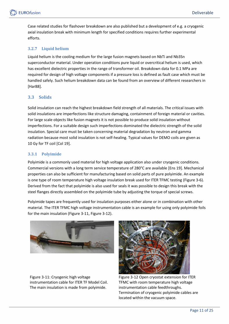
Polyimide tapes are frequently used for insulation purposes either alone or in combination with other
material. The ITER TFMC high voltage instrumentation cable is an example for using only polyimide foils
for the main insulation (Figure 3-11, Figure 3-12).
Figure 3-11: Cryogenic high voltage instrumentation cable for ITER TF Model Coil. The main insulation is made from polyimide.
Figure 3-12 Open cryostat extension for ITER TFMC with room temperature high voltage instrumentation cable feedthroughs. Termination of cryogenic polyimide cables are located within the vacuum space.

Deliverable
Page 12 of 25
It should be noticed that the resistance of polyimide against partial discharge is high. Hence from the
point of operation lifetime of the ITER TFMC a relatively small cable high voltage insulation thickness
would have been sufficient. However, the thickness was selected higher in order to achieve higher
partial discharge inception voltage by the cable. Otherwise, the high partial discharges from the
polyimide cable would have make it impossible to resolve partial discharges that are generated within
the coil body.
An important application of polyimide film in fusion magnet insulation is improvement of fibre
reinforced plastic for high voltage insulation purposes.
3.3.2 Fibre reinforce plastic
Epoxy resin impregnated glass fibre reinforced plastic is a commonly used solid material. The epoxy
resin is often based on bisphenol A diglycidyl ether (DGEBA). Such kind of insulation was selected for
ITER TFMC [Ulb 05]. The radial plates were wrapped by 1.3mm glass / polyimide insulation followed by
an impregnation with DGEBA epoxy resin at about 75 ◦C followed by a curing cycle at about 125 ◦C. The
resin could penetrate through holes in the covers into the turn insulation. An 8 mm thick insulation of
combined glass – polyimide was built up to form the ground insulation of ITER TFMC. This material
combination was also impregnated with DGEBA epoxy resin. It should be noticed that polyimide is not
able to withstand the temperatures of Nb3Sn reaction heat treatment (with e.g. 650 °C for a duration
of 200 h for ITER TFMC). This was the reason for reaction heat treatment in a special reaction mould
before installation of the turn insulation. A more detailed description for resin use on superconducting
magnets can be found in [Eva 20].
Breakdown voltage as a function of the thickness of Kapton, G-10 and stacked dry-glass fabric can be
seen in Figure 3-13.
Figure 3-13: Breakdown voltage as a function of the thickness of Kapton, G-10,G-11 and stacked dry-glass fabric [Mar 14]
3.3.3 Mica
Breakdown field strength values for mica crystals were reported higher than 400 kV / mm. Breakdown
values around 20 kV / mm [Seg] are reported for plates made of mica and resin. Mica tapes are
available for wrapped insulation. Winding of the inner cables of Nb3Sn dipole magnet MSUT was a
folded mica / glass sheet wrapped with a glass fibre tape [Oud 97]. At the beginning and the end of the
turns cable deformation occurred during winding and pressing. Nevertheless, this insulation did not
suffer from any turn-to-turn shorts.

Deliverable
Page 13 of 25
3.3.4 Silicone
Silicone composites are commonly used for high voltage insulation applications. One possible use is the
moulding of this hygroscope material for high voltage bushings used in not dry air. A more important
application can be the use for high voltage connectors (Figure 3-12) on room temperature side. In this
case the dielectric strength of silicone itself is not the critical issue. The important feature is a high
voltage compatible connection, i.e. absence of flashovers between plug and socket surface. For such an
application it is important that the developed device shows no degradation by specified assembly
related to the foreseen assembly and disassembly numbers.
Figure 3-14: Room temperature high voltage instrumentation cable feedthrough design for POLO and ITER TFMC. Silicon insulation of plug (blue) provided sufficient contact to frp insulation of socket (green) to avoid flashover along boundary surface.
3.3.5 Teflon
Teflon is an important insulation for conventional instrumentation cables. Disadvantage of the material
is the low adhesion for gluing without primer and the low resistance against radiation. This material
should be therefore avoided for DEMO at least in the cryogenic region.

Deliverable
Page 14 of 25
Table 3-1: Some materials with breakdown field strength. Operation field strengths are usually selected
much lower than breakdown or 1 min withstand field strengths.
Material Breakdown field strength or voltage (peak value)
Electrode arrangement
temperature and pressure
Reference
Vacuum Saturation around 100 kV
Tip (r = 1 mm) to plane for gaps larger than about 2 mm
at 77 K [Ger 98]
Air 24.5 kV / cm AC, peak uniform field 20 °C, 0.1 MPa [Phi 82]
Air 5 kV / cm AC peak, DC positiv
needle to plane
20 °C, 0.1 MPa [Phi 82]
SF6 89 kV / cm AC, peak uniform field 20 °C, 0.1 MPa [Phi 82]
He gas 3.7 kV / cm AC, peak uniform field 20 °C, 0.1 MPa [Phi 82]
Liquid nitrogen
6 kV / mm AC, peak Sphere (20 mm) to plane
77 K, 0.1 MPa [Hay 18]
Liquid helium ±22 kV DC Plane to plane, 1 mm gap
4.4 K, 0.1 MPa [Har 88]
Liquid helium -10 kV DC Plane to plane, 1 mm gap
4.4 K, 0.1 MPa, heater 5 W / cm
[Har 88]
Polyimide > 35 kV / mm DC ISO 60243-1 23 °C [Ens 19]
Polyimide tape Kapton® Type HN
12 µm: 303 kV / mm
60 Hz, 500 V/sec rise
ASTM D-149 1/4 inch electrodes
[DuP 21]
Mica (Phlogopit) resin plate
>20 kV / mm IEC 243 [Seg]

Deliverable
Page 15 of 25
4 Technical specifications
A large number of high voltage component types are necessary for fusion magnets. Number and kind
of types is depending on fusion magnet and fusion magnet system design. Even the high voltage
specifications may be different for the various high voltage components depending on expected
voltage stress during operation and faults.
Nevertheless, it makes sense to collect some typical values for DEMO magnets. With these values some
specifications for the high voltage components may be derived.
Table 4-1: Overview of some design parameters of POLO coil and DEMO
Polo [Bay 97]
ITER TF DEMO Example
Operation voltage 23 kV 6 kV Insulation breaks
Maximum operation pressure of coil
2.5 MPa Insulation break
Vacuum 10-10 MPa Cryogenic high voltage instrumentation cable
Minimum temperature 4 K Cryogenic instrumentation cable feedthrough
Maximum temperature 300 K Room temperature instrumentation cable feedthrough
Leak rate 10-8 hPa l / s
Axial cryogenic insulation break
Helium mass flow per current lead 0.5 g / s Axial insulation break
It must be considered that some specifications can preferably be used for mock-ups only and hardly
during tests on the coil, e.g. a Schering Bridge test on a completed coil with slightly changed dissipation
factor will hardly cause an intensive search for the origin by Schering Bridge due to a tight time
schedule. In contrast, for testing during component development phase the investigation with a
Schering Bridge can be an interesting issue. Partial discharge measurement is also an interesting
destruction free method of insulation diagnostic. On the other hand, an acceptance rejection of a
complete coil only based on partial discharge data may be replaced by comparison with results for
other coils and potentially more detailed insulation inspection for this coil. It will be difficult to specify
fixed values of partial discharge activity or dissipation factor as acceptance criterion in advance.
Specifications must be done with a view for the total system because some values make only sense
considering also the properties e.g. of the neighbouring component.
KIT proposes for the present DEMO work package the starting with two high voltage components for
further investigation, namely the cryogenic high voltage instrumentation cable feedthrough and the
axial room temperature insulation break. The cryogenic high voltage instrumentation cable wire
feedthrough is described more detailed in the next section.

Deliverable
Page 16 of 25
4.1 Specification for a cryogenic high voltage instrumentation cable wire
feedthrough
The routing of high voltage instrumentation wires through the coil solid insulation to the part of the
high voltage cable located within the vacuum space is often reported as source of insulation faults [JT
21], [Wu 10], [Sch 06]. Fiddling of the wires just through the solid insulation is not a technique which
can be considered as compatible for a reliable insulation design. Instead, a special feedthrough design
is one option which must satisfy the following requirements:
Lifetime 30 years
Dimensions tbd
Number of wires (per cable) tbd
Pitch value (if necessary) same as cable
Resistance per wire ≤ 0.3 Ohm
Screen connections available for high voltage and ground
screen of cable
Compressive stress 2 kN (like ITER breaks ITER_D_2NJ8NJ)
(protected or resistant against standing
on it)
Tensile stress 2 kN
Torsion stress 50 Nm (half like ITER breaks
ITER_D_2NJ8NJ)
Mechanical cycles 60000 cycles with 50% of load (see
ITER_D_2NJ8NJ)
Chemical adhesive for gluing with cable and coil
insulation, paintable with (semi-)
conductive varnish to form a Paschen
tight device with all neighbouring parts
Operation temperature 4 K – 300 K (also suitable for room
temperature high voltage tests)
Leak rate 10-8 hPa l / s
Outgassing rate < 1 x 10⁻⁹ Pa m3 s-1 m-2, after
conditioning in vacuum
Maximum magnetic field: 12 T
Radiation dose over 20 years 1 MGy
Operation voltage tbd
Voltage during most severe considered fault tbd

Deliverable
Page 17 of 25
Test voltage, DC tbd
Test voltage, AC, peak value tbd
Test voltage, standard lightning impulse tbd
(Test voltage, chopped tbd)
Test voltage wire to wire or pin to pin tbd
(Partial discharge (PD) inception voltage tbd)
(Maximum apparent charge during PD measurement tbd)
Maximum length on top of the unequipped coil body (without cables) 0.5 m
5 High voltage testing
5.1 Principles for high voltage testing of coils
High voltage testing on DEMO and DEMO components should be arranged according to basic principles
of insulation co-ordination. Principles and rules of insulation co-ordination can be derived from
standard [IEC 71-1] although DEMO is no three-phase AC system.
In a first step a system analysis must be started. This analysis shall deliver the voltages and
overvoltages in amplitude, shape and duration depending on location. Since the DEMO design is
presently (year 2021) under discussion, especially concerning the maximum terminal operation
voltages, no fixed data are presently available. Representative voltages and overvoltages for each class
of the calculated voltages and overvoltages shall be determined. For AC systems typical standard
voltage shapes are AC with sinus waveform, standard switching and standard lightning impulse. Since
the common high voltage equipment is intended for tests with such waveforms one possible strategy is
to divide the voltage waveform classes of DEMO (e.g. discharge with ms front and several seconds or
10th of seconds equivalent discharge time constant) in such a way that tests can also be performed
with already existing test equipment from power engineering. In this case the following waveforms
from power engineering test may be applicable:
DC: a voltage that is time-independent. In reality a test with DC comprises also a ramp up and ramp
down of the voltage. If this ramping is done similar to the equivalent discharge time such a test can be
considered as representative for the fall of a TF coil discharge. An advantage of this waveform is the
low power of the test equipment for high resistive test samples (e.g. no water hoses assembled). This
means that in case of an occurrence of an insulation fault only the capacitive energy of the test sample
is important for the potential material destruction. Hence the DC waveform is usually selected as a first
high voltage test and during Paschen tests. In addition, the (apparent) insulation resistance can be
derived by DC testing.
AC: The test voltage has the sinus waveform with a frequency of 50 Hz or 60 Hz. This voltage can be
used for testing fusion magnets related to waveforms with rise times of few ms (e.g. rise time during
fast discharge). It may be discussed if the usual bipolar voltage can and shall be replace with unipolar
sinus waveform by using a Villard circuit. Bipolar AC waveform can also be used for destruction free
insulation diagnostic with partial discharge measurement and Schering bridge because for this

Deliverable
Page 18 of 25
waveform the most knowledge exists based on the usual testing from power engineering (bushings,
transformers etc.).
Impulse testing: The test voltage has the waveform of an impulse. In power engineering the waveforms
for switching impulse (SI) and standard lightning impulse (LI) are specified. The LI with its rise time of
1.2 µs and time to half value of 50 µs can be considered as a useful waveform shape for transients
occurring after triggering the switch for discharging the capacitor bank in order to obtain a zero
transition in the vacuum breaker during counter acting current switching. In addition, the rise time of
the LI may be reprehensive for voltage transients generated by insulation faults. It is important that
such impulse tests are analysed in advance for application on large samples like completed fusion
magnets in order to avoid local overstress during high voltage testing.
Chopped voltage: No standard waveform is specified in [IEC 71-1] for fast transients with front times ≤
100 ns instead it is referenced to specifications of the relevant apparatus committees. For transformer
bushings and transformers chopped wave lightning impulse tests (LIC) where specified as lightning
impulses cut after a time to chopping between 3 μs and 6 μs. In power engineering the reason for fast
transients is different as for fusion magnets. Hence it may be preferable to chop other waveforms like
DC. It is very important that such impulse tests are analysed in advance for application on large
samples like completed fusion magnets in order to avoid too high local overvoltages during testing.
Rules for selection of testing of completed coils are described in [Fin 04]:
The proposed ideal test voltages derived from the following considerations:
The standard rule for voltage tests related to single fault events is proposed to be
2 * Ufault + 1 kV. The value is rounded up to integer values (e. g. 2*8.1 kV + 1 kV = 17.2 kV =>
18 kV).
The test voltage for values < 5 kV is taken as 5 kV if there is no special reason to select a lower
voltage.
In case of a radial plate design: For radial plate and conductor insulation the higher value is
taken for both.
The (terminal) test voltage for impulse voltages with rise times in the range of some µs may be
reduced to avoid too high stress of radial plate and conductor insulation.
According to the standard for power transformers ([IEC 76-3], chapter 9) repetition of tests on
new power transformers are to be performed with 100% and the level is reduced to 80% for
most voltage tests of refurbished or serviced transformers, unless otherwise agreed upon. (The
80% level may be DEMO relevant for e. g. PD testing after several years of operation.)
The test voltages for the first test series should be increased with a certain factor if the manufacturer
or the DEMO community prefers a higher safety margin for the first test compared to later tests. If the
manufacturer wants to have added a certain safety margin for the manufacturing tests the margin
must be added to the specified test levels.
In power engineering, the devices were commonly subjected to an initial standardized test series and
then operated for 30 years or longer without further test series. The situation is different for fusion
magnets. A large number of high voltage test series is useful before first full fusion reactor operation in
order to notice a potential problem as early as possible. In addition, a Paschen tight design generates
large size systems where parts cannot be tested separately from each other. Multiple testing for
manufacturing control, fault localization or after potential repair activities must be covered by the
dielectric design without starting of degradation. Hence for achieving a sufficient long-term high

Deliverable
Page 19 of 25
voltage reliability a voltage application for 30 years with the specified test voltages should be
predefined in order to avoid limitation in test time or number of tests. This does not mean that
individual tests take a long time or longer than needed or that all test are performed with full specified
test voltage but it is not necessary to care about potential limitation of test number and time or
voltage value (as long as it is equal or lower than the specified test voltage level). The cost impact of
this specification can be expected as relatively low for a reliable design. It is also in the hand of the
manufacturer to specify sufficient high test voltage levels when the insulation is incomplete, e.g., no
vacuum impregnation, to eliminate fabrication faults as early as possible and allow repair.
The increasing of the test voltage may be performed in defined steps related to the maximum test
voltage. A possible sequence is 10%, 30%, 50%, 70%, 90%, 100%. Especially before polarity reversal
with impulse tests it is not allowed to start with a 100% impulse. Instead at least one initial 30%
impulse is required before testing with full test voltage amplitude of reversed polarity.
Type and routine high voltage tests should follow the same level as the coil tests. Tests at higher levels
are to be performed on high voltage components during development on mock-ups and prototype
samples in order to analyse the safety factors.
5.1.1 Paschen tests
The proposal for Paschen testing is mainly derived from [Fin 09]. A reliable high voltage operation even
under vacuum breakdown in the cryostat requires an entire encapsulation with solid insulation and
covering of this insulation with conductive material (e.g. conductive paint). Such a “Paschen tight”
concept must be verified by a Paschen test where the sample is subjected to a transition of the
Paschen curve.
A vacuum vessel is necessary for such a test. Every test sample must be prepared to be Paschen tight.
For superconducting coils an appropriate time of a Paschen test is after connection of the high voltage
instrumentation path at the manufacturer site. But this makes only sense in case the fusion reactor
facility site allows to let have connected the cryogenic cable paths during coil installation in the
cryostat. Otherwise open ends must be either encapsulated in a Paschen tight manner or guided in a
Paschen tight manner to the ambient.
Because it is more time consuming to achieve a good vacuum in a large vessel which had been filled
with air than filling an “empty” vessel with air up to ambient pressure it is proposed to start Paschen
testing from vacuum.
One method is to apply permanently the DC test voltage while increasing the pressure continuously
from vacuum till ambient pressure. Another method is to increase the pressure in steps. The steps
should consider likely gap lengths of the fault location in the ground location. But even taking into
account a minimum thickness of a fusion magnet for the ground insulation of a certain length, shorter
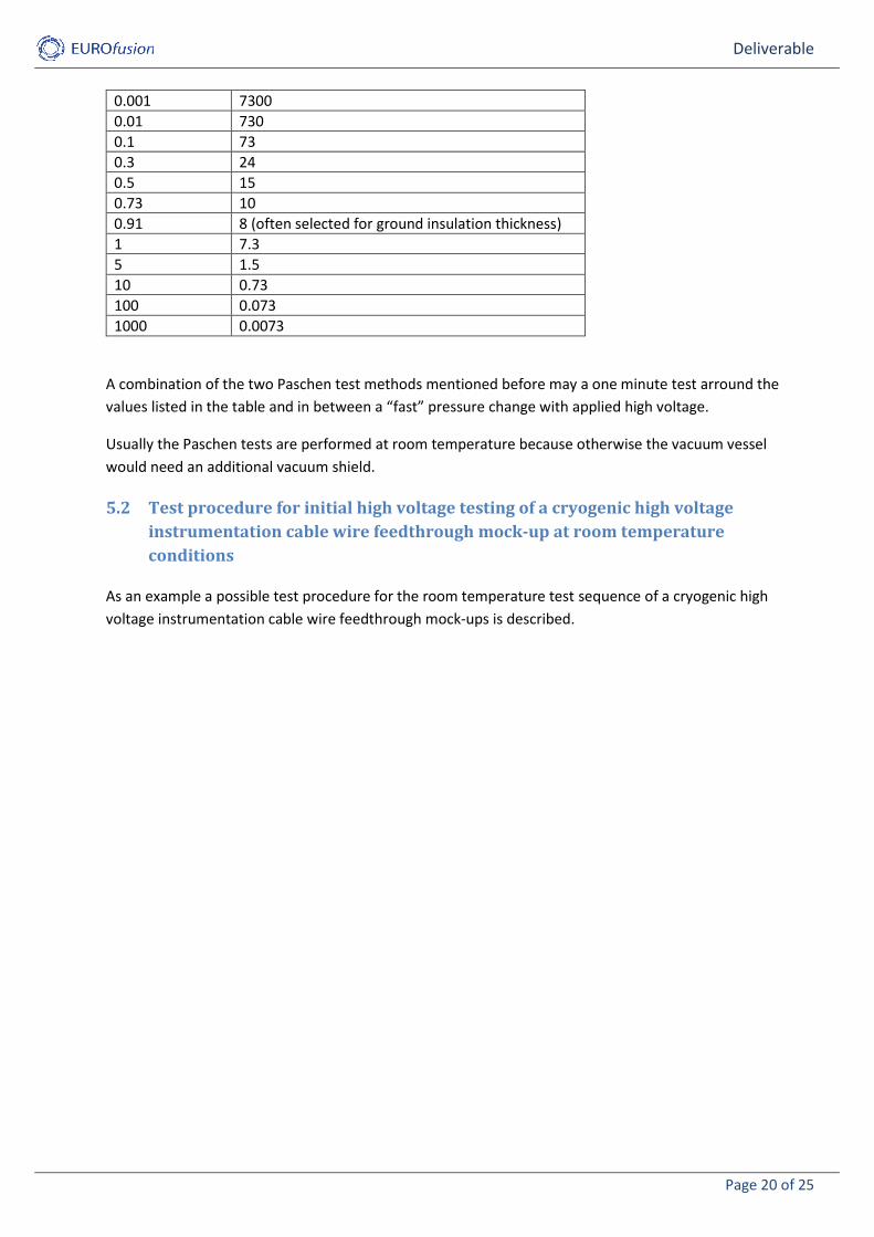
gap lengths are not impossible (e.g. by invasion of conductive paint in a gap). The following table shows
a set of interesting pressure values and the belonging gap length for Paschen Minimum conditions with
a Paschen Minimum value in air at room temperature of p * d = 7.3 bar µm:
Table 5-1: Pressure steps for Paschen test considering the belonging gap lengths in air for reaching
Paschen Minimum conditions.
p / hPa d / mm
Deliverable
Page 20 of 25
0.001 7300
0.01 730
0.1 73
0.3 24
0.5 15
0.73 10
0.91 8 (often selected for ground insulation thickness)
1 7.3
5 1.5
10 0.73
100 0.073
1000 0.0073
A combination of the two Paschen test methods mentioned before may a one minute test arround the
values listed in the table and in between a “fast” pressure change with applied high voltage.
Usually the Paschen tests are performed at room temperature because otherwise the vacuum vessel
would need an additional vacuum shield.
5.2 Test procedure for initial high voltage testing of a cryogenic high voltage
instrumentation cable wire feedthrough mock-up at room temperature
conditions
As an example a possible test procedure for the room temperature test sequence of a cryogenic high
voltage instrumentation cable wire feedthrough mock-ups is described.
Deliverable
Page 21 of 25
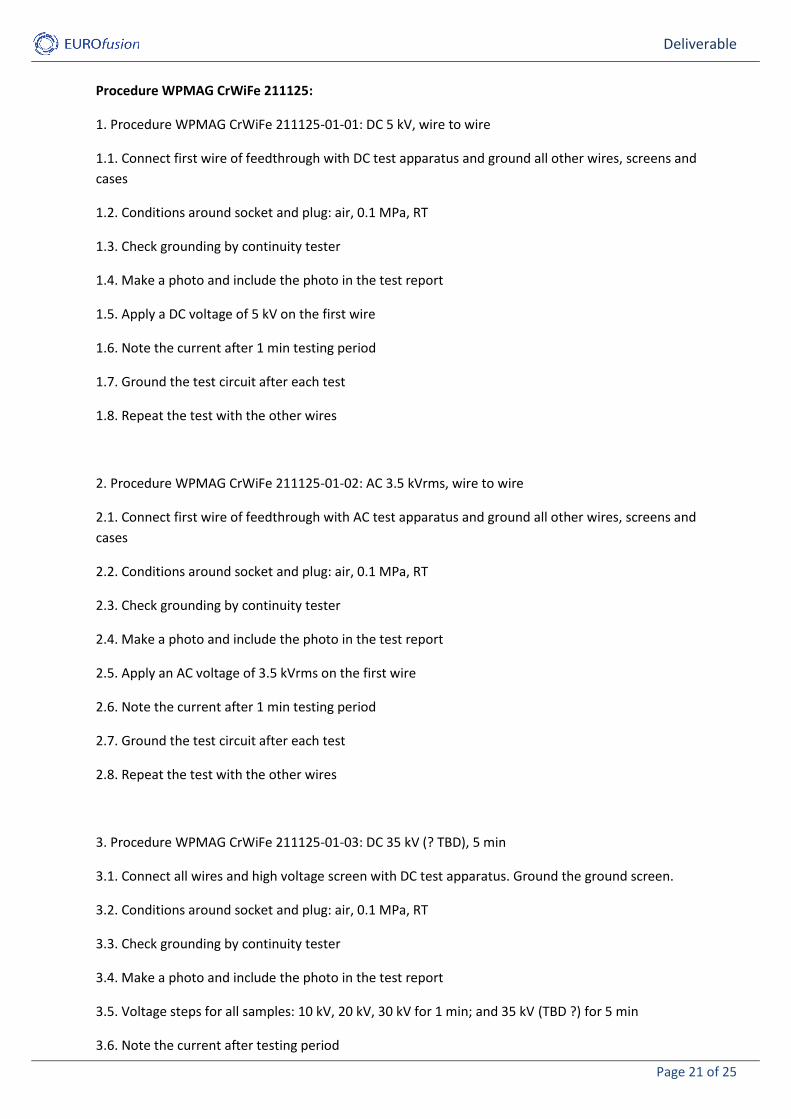
Procedure WPMAG CrWiFe 211125:
1. Procedure WPMAG CrWiFe 211125-01-01: DC 5 kV, wire to wire
1.1. Connect first wire of feedthrough with DC test apparatus and ground all other wires, screens and
cases
1.2. Conditions around socket and plug: air, 0.1 MPa, RT
1.3. Check grounding by continuity tester
1.4. Make a photo and include the photo in the test report
1.5. Apply a DC voltage of 5 kV on the first wire
1.6. Note the current after 1 min testing period
1.7. Ground the test circuit after each test
1.8. Repeat the test with the other wires
2. Procedure WPMAG CrWiFe 211125-01-02: AC 3.5 kVrms, wire to wire
2.1. Connect first wire of feedthrough with AC test apparatus and ground all other wires, screens and
cases
2.2. Conditions around socket and plug: air, 0.1 MPa, RT
2.3. Check grounding by continuity tester
2.4. Make a photo and include the photo in the test report
2.5. Apply an AC voltage of 3.5 kVrms on the first wire
2.6. Note the current after 1 min testing period
2.7. Ground the test circuit after each test
2.8. Repeat the test with the other wires
3. Procedure WPMAG CrWiFe 211125-01-03: DC 35 kV (? TBD), 5 min
3.1. Connect all wires and high voltage screen with DC test apparatus. Ground the ground screen.
3.2. Conditions around socket and plug: air, 0.1 MPa, RT
3.3. Check grounding by continuity tester
3.4. Make a photo and include the photo in the test report
3.5. Voltage steps for all samples: 10 kV, 20 kV, 30 kV for 1 min; and 35 kV (TBD ?) for 5 min
3.6. Note the current after testing period

Deliverable
Page 22 of 25
3.7. Ground the test circuit
4. Procedure WPMAG CrWiFe 211125-01-04: AC 24.7 kVrms (? TBD), 5 min, eventually with partial
discharge (PD) measurement
4.1. Connect all wires and high voltage screen with AC test circuit. Ground the ground screen
4.2. Conditions around socket and plug: air, 0.1 MPa, RT
4.3. Check grounding by continuity tester
4.4. Make a photo and include the photo in the test report
4.5. rms voltage steps for all samples: 3.54 kV, 7.1 kV, 14.1 kV, 21.2 kV for 1 min; and 24.7 kV for 5 min.
The step duration is 3 min instead of 1 min in case of partial discharge measurement in apparent
charge vs. high voltage phase angle mode.
4.6. Ground the test circuit
5. Procedure WPMAG CrWiFe 211125-01-05: Impulse test 35 kV
5.1. Connect all wires and high voltage screen with the impulse test circuit. Ground the ground screen.
5.2. Conditions around socket and plug: air, 0.1 MPa, RT
5.3. Check grounding by continuity tester
5.4. Make a photo and include the photo in the test report
5.5. Crest value is 35 kV, some impulses at lower voltages are necessary to adjust and confirm the
parameters of standard LI (1.2 μs virtual front time, 50 μs time to half value)
5.6. 10 impulses for both polarities without breakdown are necessary to fulfil the test, additionally one
impulse with lower crest value (about 30%) after polarity change
5.7. Ground the test circuit
6. Procedure WPMAG CrWiFe 211125-01-07: Paschen test 35 kV (? TBD)
6.1. Arrange a sample in a vacuum vessel and connect a DC test apparatus to all active wires and the
high voltage screen. Connect a vacuum and a pressure measurement.
6.2. Conditions around plug: air, 0.1 MPa, RT, Evacuate the area around the socket for at least 3 h
(preferably longer e.g. over night or week end)
6.3. Check grounding by continuity tester, control the vacuum with a target value of p ≤ 0.002 hPa
6.4. Adjust zero point of manometer scaling
6.5. Make a photo and include the photo in the test report

Deliverable
Page 23 of 25
6.6. Increase the voltage to 35 kV (? TBD)
6.7. Increase the pressure, at hold points keep the pressure for at least 1 min. It is not necessary to
ramp the voltage down and up between the steps if pressure adjustment duration if it can be done
electrically safely. Take at least the following hold points: ≤0.002 hPa, 0.01 hPa, 0.1 hPa, 0.5 hPa, 1 hPa,
10 hPa, 100 hPa, ambient pressure
6.8. Note the current at each hold point pressure at the end of the test minute
6.9. Ground the test circuit
It is indispensable that the sample is subjected to thermal cycling, too, and also afterwards tested of
the dielectric strength. A test series under cryogenic conditions is also recommended. The Paschen test
may be skipped for the test procedure under cryogenic conditions because it is a large effort to build-
up an appropriate test setup.
“Long duration” high voltage testing (10 h) should be added for the final test series after all (3 up to 5)
thermal cycles and mechanical stress tests. Then tests at higher voltages will be added to find the
dielectric limits of the mock-up.
6 Limitations of test facilities at KIT
KIT proposes the following maximum lengths for the mock-ups:
Cryogenic high voltage instrumentation cable feedthrough: maximum length in cryostat only: 0.7 m;
minimum cable length outside cryostat: eventually 4 m, or suitable bushing, tbd (also depending on
test voltage and used cable)
Room temperature insulation break for testing in Waheffca: 0.75 m (including steel pipes with KF-
flanges)
Longer mock-up lengths may be tested on request.
7 References
[Bal 19] J. Baldzuhn at al., “Spark Detection and Search for High-Voltage Paschen Leaks in a Large Superconducting Coil System”, transactions on plasma science, Vol. 47, No. 11, pp. 5125-5138, 2019
[Bay 97] M. Darweschsad, G. Friesinger, R. Heller, M. Irmisch, H. Kathol, P. Komarek, W. Maurer, G. Nöther, G. Schleinkofer, C. Schmidt, Ch. Sihler, M. Süsser, A. Ulbricht, F. Wtichner (1995), ”Development and test of the poloidal field prototype coil POLO at the Forschungszentrum Karlsruhe”, Fusion Engineering and Design 36, pp. 227-250, 1997
[Bur 14] A. S. Bursikov, N. M. Voronin, S. M. Gavrilov, V. A. Grinchenko, Yu. A. Klimchenko, V. A. Korsunskiy, O. A. Kovalchuk, A. A. Lancetov, E. L. Marushin, A. A. Mednikov, I. Yu. Rodin, and A. V. Safonov,“ Novel cryogenic high voltage insulation breaks with spiral channel” AIP Conference Proceedings 1573, pp. 1700-1706, 2014
[Col 19] M. Coleman, Y. Hörstensmeyer, F. Cismondi, “DEMO tritium fuel cycle: performance, parameter explorations, and design space constraints,” Fusion Engineering and Design, Vol. 141, pp. 79-90, 2019

Deliverable
Page 24 of 25
[DuP 21] DuPont, “DuPont Kapton summary of properties,” datasheet, p. 10, EI-10142 (5/21)
[Ens 19] Ensinger Sintimid GmbH, “TECASINT 1011 natural - Stock Shapes (rods, plates, tubes)”, datasheet, Version: AC, 2019
[Eva 20] D. Evans, “Resins for superconducting magnet construction – an overview of requirements, processing and properties”, IOP Conference Series.Materials Science and Engineering, 756(1), 2020
[Fin 04] A. Fink, W. H. Fietz, A. M. Miri, X. Quan, A. Ulbricht, “Study of the transient voltage behaviour of the present ITER TF coil design for determination of the test voltages and procedures,” Forschungszentrum Karlsruhe, Scientific Report FZKA 7053, 2004
[Ger 98] J. Gerhold, “Properties of cryogenic insulants,” Cryogenics, Volume 38, Issue 11, pp 1063-1081, 1998
[Har88] M. Hara, T. Kaneko, K. Honda, “Thermal-Bubble Initiated Breakdown Characteristics of Liquid Helium and Nitrogen at Atmospheric Pressure,” IEEE Transactions on Electrical Insul., Vol. 23, No. 4, 1988
[Hay 18] N. Hayakawa, K. Ishida, M. Mimbu, H. Kojima, S. Isojima, M. Kuwata, "Volume Effect of Dynamic Breakdown Strength in LN2 for Insulation Design of Resistive Superconducting Fault Current Limiters," Transactions on Applied Superconductivity, vol. 28, no. 4, pp. 1-4, 2018
[Hay 19] N. Hayakawa, M. Mimbu, H. Kojima, S. Isojima and M. Kuwata, "Dynamic Breakdown Characteristics of Pancake Coil Model for Resistive-Type Superconducting Fault Current Limiters," IEEE Transactions on Applied Superconductivity, vol. 29, no. 5, pp. 1-6, Aug. 2019
[IEC 71-1] IEC standard IEC 60071-1, “Insualtion co-ordination – Part 1: definitions, principles and rules”
[IEC 71-2] IEC standard 60071-2, “Insulation co-ordination - Part 2: application guidelines”
[IEC 76-3] Power Transformers - Part 3: Insulation levels, dielectric tests and external clearances in air
[Irm 96] M. Irmisch, A. Ulbricht, A. “Hochspannungskomponenten für die supraleitende Poloidalfeld-Modellspule POLO”, Wissenschaftliche Berichte, FZKA-5568, 1996
[JT 21] JT60 SA, “Integrated Commissioning Status on 09.07.2021”, Retrieved from: www.jt60sa.org/wp/category/news/
[Mar 14] R. P. Reeda, N. N. Martovetsky, “Electrical Insulation Systems for the ITER CS Modules,”AIP Conference Proceedings 1574, p. 357, 2014
[Pha 21] N. S. Phan, W. Wei, B. Beaumont, N. Bouman, S. M. Clayton, S. A. Currie, T. M. Ito, J. C. Ramsey, G. M. Seidel “A study of DC electrical breakdown in liquid helium through analysis of the empirical breakdown field distributions”, Journal of Applied Physics 129, 083301, 2021
[Phi 82] Eugen Philippow, Taschenbuch Elektrotechnik, Vol. 6, pp.279 ff and pp. 291
[Oud 97] A. den Ouden, W. Wessel, H. Krooshoop, ; H. ten Kate, “Application of Nb3Sn superconductors in high-field accelerator magnets”, transactions on applied superconductivity, vol. 7, no. 2. pp. 733-737, 1997
[Sch 06] H. Scheller et al., "Paschen Testing on W7-X Coils and Components in the BNN Test Facility," in IEEE Transactions on Applied Superconductivity, vol. 16, no. 2, pp. 759-762, 2006
[Seg] Segliwa GmbH, “Sewitherm P“, data sheet

Deliverable
Page 25 of 25
[Sim 94] N. J. “Cryogenic Properties of Inorganic Insulation Materials for ITER Magnets: A Review” (NISTIR--5030), United States, page 151, 1994
[Sko 11] N. Skoro, D. Maric, G. Malović, W. G. Graham, W. Z. Petrović, “Electrical breakdown in water vapor”. American Physical Society, Phys. Rev. E, volume 84, iss. 5, pages 055401, 2011
[ulb 05] A. Ulbricht at al., “The ITER toroidal field model coil project,” Fusion Engineering and Design, Vol. 73, Iss. 2–4, pp. 189-327, 2005
[Wu 10] Y. Wu, "Experience in Operating Safety of EAST Superconducting Magnets," Transactions on applied superconductivity, vol. 20, no. 3, pp. 431-437, 2010