PGR-3200 MANUAL INSULATION MONITOR - Littelfuse
12
Tel: +1-800-832-3873 E-mail: [email protected] www.littelfuse.com PGR-3200 MANUAL INSULATION MONITOR REVISION 3-F-032320 Copyright © 2020 Littelfuse. All rights reserved. Document Number: PM-1025-EN
-
Upload
khangminh22 -
Category
Documents
-
view
1 -
download
0
Transcript of PGR-3200 MANUAL INSULATION MONITOR - Littelfuse
Tel: +1-800-832-3873E-mail: [email protected]
www.littelfuse.com
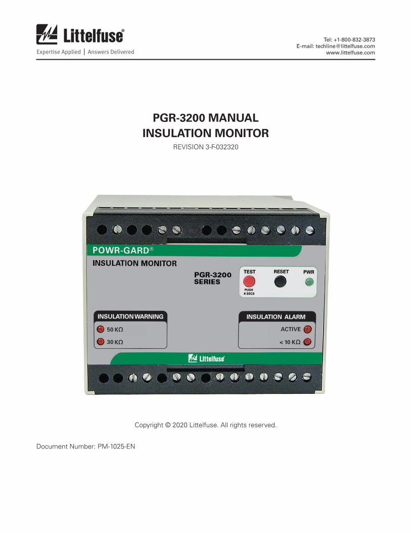
PGR-3200 MANUALINSULATION MONITOR
REVISION 3-F-032320
Copyright © 2020 Littelfuse. All rights reserved.
Document Number: PM-1025-EN

Page iREV. 3-F-032320 PGR-3200 Insulation Monitor
This page intentionally left blank.

Page iiREV. 3-F-032320 PGR-3200 Insulation Monitor
TABLE OF CONTENTSSECTION PAGE
1 General .......................................................................................12 Operation....................................................................................1
2.1 Relay Operating Mode .........................................................12.2 Front-Panel Controls .............................................................1
2.2.1 Reset ........................................................................12.2.2 Test ..........................................................................1
2.3 Front-Panel Indication ..........................................................12.3.1 Power .......................................................................12.3.2 Insulation Warning ..................................................12.3.3 Active .......................................................................12.3.4 Insulation Alarm ......................................................1
2.4 Analog Output ......................................................................12.5 Remote Reset .......................................................................12.6 Remote Test ..........................................................................1
3 Installation .................................................................................33.1 PGH-5000 and PGH-6000 .....................................................4
4 Technical Specifications ........................................................64.1 PGR-3200 ..............................................................................64.2 PGH High-Tension Couplers .................................................7
5 Ordering Information ..............................................................76 Performance Test.....................................................................7
6.1 Insulation Test ......................................................................7Appendix A PGR-3200 Revision History ..................................8
LIST OF FIGURES
FIGURE PAGE
1 PGR-3200 Outline and Mounting Details ...................................22 Connection Diagram for Ungrounded Systems Under 1.3 kV ................................................................................33 Connection Diagram for Ungrounded 5-kV Systems ..................34 PGH-5000 Outline and Mounting Details ...................................45 PGH-6000 Outline and Mounting Details ...................................56 PGA-0510 Analog Ohm Meter ....................................................5
DISCLAIMER
Specifications are subject to change without notice. Littelfuse, Inc. is not liable for contingent or consequential damages, or for expenses sustained as a result of incorrect application, incorrect adjustment, or a malfunction.

Page iiiREV. 3-F-032320 PGR-3200 Insulation Monitor
This page intentionally left blank.

Page 1REV. 3-F-032320 PGR-3200 Insulation Monitor
1. GENERAL The PGR-3200 Insulation Monitor measures phase-to-ground resistance to detect electrical-insulation failure in an ungrounded power utilization system. It provides three levels of detection with a 50-kΩ warning with an LED and output contact indication, a 30-kΩ warning with LED indication, and a 10-kΩ alarm with LED and output contact indication. An analog output is provided for predictive maintenance trending.
The PGR-3200 can be used to detect faults in ungrounded systems up to 6 kV. It can be directly connected to a system up to 1.3 kV, single or three phase, 50 or 60 Hz. A PGH-series high-tension coupler is required for 5- and 6-kV systems.
2. OPERATION
The PGR-3200 actively monitors insulation resistance when it is connected to the supply voltage. All conductors connected to the monitored circuit are included in the insulation measurement (see Figure 2).
2.1 Relay Operating Mode The PGR-3200 output relays operate in the non-fail-safe mode; they energize when an insulation warning or alarm occurs.
2.2 Front-Panel Controls2.2.1 Reset The front-panel RESET switch is used to reset latching trips. Cycling the supply voltage will also reset the PGR-3200. See Section 2.5.
2.2.2 Test All LEDs will light and output relays will energize when the TEST button is pressed for at least 8 s.
2.3 Front-Panel Indication2.3.1 Power The green LEDs labelled PWR indicates presence of supply voltage.
2.3.2 Insulation Warning The red LEDs labelled 50 kΩ and 30 kΩ will light when those respective insulation resistance values, or lower are measured.
2.3.3 Active The red LED labelled ACTIVE indicates the monitor is enabled.
2.3.4 Insulation Alarm When insulation resistance measures 10 kΩ or less, the red LED labelled <10 kΩ will light.
2.4 Analog Output A non-isolated, 0- to 1-mA output (terminals 25 and 26) indicates insulation resistance. The metering output relates to an insulation-resistance range of 0 to infinity using optional meter PGA-0510 (see Figures 2, 3 and 6).
2.5 Remote Reset When remote-reset terminals 18 and 19 (alarm) or 21 and 22 (warning) are not connected, a warning or alarm remains latched until the RESET switch is pressed or the remote-reset terminals are momentarily opened.
If the remote-reset terminals are connected, the PGR-3200 operates in non-latching mode; a warning or alarm will reset when the fault is removed.
2.6 Remote Test When terminal 29 is connected to ground the monitor will alarm (see Figures 2 and 3). Response to a test input can take several seconds.

Page 2REV. 3-F-032320 PGR-3200 Insulation Monitor
POWR-GARD
INSULATION MONITORPGR-3200SERIES
PWRTEST RESET
PUSH 8 s
INSULATION ALARMINSULATION WARNING
ACTIVE
<10 K
50 K
30 K
16 17 18 19 20 21 22 23 24 25 26 27 28 29 30ANALOGOUTPUT
ENABLE PGH>1.3 KV
50 kREMOTERESET
10 kREMOTERESET
1 2 3 4 5 6 7 8 9 10 11 12 13 14 15
L1L2/N10 k
INSULATION
PHASE<1.3 KV
50 kINSULATION
24 V
2 3 4 5 6 7 81
17 18 19 20 21 22 2316
M
SUPPLY
INSULATION MONITOR
PGR-3200SERIES
9 10 11 12 13 14
24 25 26 27 28 29
15
30
(Alarm) (Warning)
Optional links to enable non-latching mode
OptionalExternal
Test
Remote Resetor Latching Mode
ANALOGOUTPUT
L1L2/N
ENABLE
10 kINSULATION
PGH>1.3 KV
PHASE<1.3 KV
50 kINSULATION
50 kREMOTERESET
10 kREMOTERESET
PGA-0510OptionalRemoteReset
18
21
19
22
PGH-5000A
M E
24 Vac
NOTE: 120/24 OR 240 VAC, 50/60 HZ ARE ORDERING OPTIONS. USE SPECIFIED SUPPLY VOLTAGE
(SEE NOTE)
NOTES:
1. DIMENSIONS IN MILLIMETRES (INCHES).
2. MOUNTING SCREWS: M4 x 13 OR 8-32 x 0.50.
3. OVERALL DIMENSION WHEN MOUNTED ON DIN EN50022 35 mm x 7.5 mm TOP-HAT RAIL.
4. 24 V INPUT IS AVAILABLE ONLY FOR THE PGR-3200-120 ORDERING OPTION.
TOP99.80
(3.93)
75.0
(2.9
5)
113.0 (NOTE 3)
(4.45)
FRONT SIDE
BOTTOM
MOUNTING DETAIL
7.4
(0.29)
99.80(3.93)85.0
(3.35)
61.2
(2.4
1)75
.0(2
.95)
6.9
(0.2
7)
Figure 1. PGR-3200 Outline and Mounting Details.

Page 3REV. 3-F-032320 PGR-3200 Insulation Monitor
3. INSTALLATIONNOTE: Mounting, terminal-block connections, and wiring must conform to applicable local electrical codes. Check all applicable codes prior to installation.
The PGR-3200 can be surface or DIN-rail mounted (see Figure 1).
Use terminal 6 (L1) as the line terminal and terminal 5 (L2/N) as the neutral terminal. Connect terminal 30 to ground.
For systems up to 1.3 kV, connect terminal 2 to one phase on the load side of the starter.
Connect terminals for latching operation, remote reset, and remote test as required (see Sections 2.5 and 2.6 and Figures 2 and 3).
Connect an optional PGA-0510 Analog Ohm Meter to terminals 25 and 26. Meter outline, dimensions, and cutout size are shown in Figure 6.
SUPPLY (SEE NOTE)
24 Vac
1 2 53 4 6 7 8 9 10 11 15141312PHASE<1.3 KV
L2/N L1
INSULATIONMONITOR
10 kINSULATION
50 kINSULATION
(Alarm) (Warning)
PGR-3200SERIES
Remote Resetor Latching Mode
50 KREMOTERESET
10 KREMOTERESET
ANALOGOUTPUT
ENABLE
PGH>1.3 KV
16 17 21201918 2322 2524 2726 28 3029
Optional External
Test
OptionalRemote Reset
M
PGA-0510
NOTE: 120/24 OR 240 VAC 50/60 HZ ARE ORDERING OPTIONS. USE SPECIFIED SUPPLY VOLTAGE.
18
21
1922
Optional links to enable non-latching mode
Figure 2. Connection Diagram for Ungrounded Systems Under 1.3 kV.
SUPPLY (SEE NOTE)
24 Vac
1 2 53 4 6 7 8 9 10 11 15141312PHASE<1.3 KV
L2/N L1 24 V
INSULATIONMONITOR
10 kINSULATION
50 kINSULATION
(Alarm) (Warning)
PGR-3200SERIES
Remote Resetor Latching Mode
50 KREMOTERESET
10 KREMOTERESET
ANALOGOUTPUT
ENABLE
PGH>1.3 KV
16 17 21201918 2322 2524 2726 28 3029
Optional External
Test
OptionalRemote Reset
M
PGA-0510
NOTE: 120/24 OR 240 V AC 50/60 HZ ARE ORDERING OPTIONS. USE SPECIFIED SUPPLY VOLTAGE.
18
21
1922
PGH-5000
A
M E
Optional links to enable non-latching mode
Figure 3. Connection Diagram for Ungrounded 5-kV Systems.

Page 4REV. 3-F-032320 PGR-3200 Insulation Monitor
Revision:
Coupling Voltage:
PGH-50005 KV HIGH TENSION COUPLER
Serial No: 1-800-TEC-FUSE (1-800-832-3873)Made in Saskatoon, Canada
Impedance to Ground:
Current to Ground: 2.5 mA Max.
Formerly HTC 5000
E M
RELAY
E
HT
PGH-5000A
5,000 Vac Max.
> 2 M
MAXIMUMVOLTAGE
AC 5000V
PGH-50005kV HIGH TENSION COUPLER
POWR-GARD
HIGH VOLTAGE
ATTENTION!BOTH GROUND CONNECTIONS MUST BE MADE AND SECURED
BEFORE CONNECTIONS TO THE RELAY AND THE HIGH VOLTAGE LINE
DANGER
E E M
A
A
Æ
Æ
44.5(1.75)
165.
1(6
.50)
95.2(3.75) 9.5
(0.38)
NOTE 2
150.
0(5
.91)
FRONT SIDE MOUNTING DETAIL
NOTES:
1. DIMENSIONS IN MILLIMETRES (INCHES).
2. MOUNTING HOLES: 5.00 mm (0.20).
3. ALL GROUND CONNECTIONS MUST BE MADE AND SECURED BEFORE CONNECTION TO RELAY AND HIGH VOLTAGE LINE.
4. CORD PROVIDED IS APPROXIMATELY 915.0 (36.00) LONG.
915.0(36.00)
Figure 4. PGH-5000 Outline and Mounting Details.
3.1 PGH-5000 and PGH-6000 For 5-kV and 6-kV systems, connect the PGR-3200 to the monitored circuit with a PGH-5000 and PGH-6000 respectively. See Figure 4 for PGH-5000 outline and mounting details. See Figure 5 for PGH-6000 outline and mounting details.
Connect protective-ground terminal ( ) to ground. Connect terminal E to ground or to PGR-3200 terminal 30, which must be grounded. Connect terminal M to PGR-3200 terminal 29. PGR-3200 terminal 2 is not used. For PGR-3200 to PGH-5000/PGH-6000 distances greater than 10 m (30 ft), use shielded
cable, and connect the cable shield to the second PGH-5000/PGH-6000 terminal E. Connect terminal A to one phase on the load side of the motor starter (see Figure 3). The PGH-5000/PHG-6000 includes 915 mm (36 in.) of high-voltage conductor.

Page 5REV. 3-F-032320 PGR-3200 Insulation Monitor
MAXIMUMVOLTAGE
AC 6000V
DANGERHIGH VOLTAGE
ATTENTION!BOTH GROUND CONNECTIONS MUST BE MADE AND SECURED
BEFORE CONNECTIONS TO THE RELAY AND THE HIGH VOLTAGE LINE
PGH-60006kV HIGH TENSION COUPLER
POWR-GARD
A
MAXIMUMVOLTAGE
AC 6000V
PGH-60006kV HIGH TENSION COUPLER
POWR-GARD
HIGH VOLTAGE
ATTENTION!BOTH GROUND CONNECTIONS MUST BE MADE AND SECURED
BEFORE CONNECTIONS TO THE RELAY AND THE HIGH VOLTAGE LINE
DANGER
E E M
Revision:
Coupling Voltage:
PGH-60006 KV HIGH TENSION COUPLER
Serial No: 1-800-TEC-FUSE (1-800-832-3873)Made in Saskatoon, Canada
Impedance to Ground:
Current to Ground: 2.5 mA Max.
Formerly HTC 6000
E M
RELAY
E
HT
PGH-6000A
6,000 Vac Max.
> 2 M
Æ
Æ
145.0(5.71)120.0(4.72)
12.50
(0.49)
12.5
0
(0.4
9)
12.5
0
(0.4
9)
175.
0(6
.89)
200.
0(7
.87)
915 (36) LONG
98.5(3.88)
FRONT SIDENOTES:
1. DIMENSIONS IN MILLIMETRES (INCHES).
2. MOUNTING HOLES: 6.35 mm (0.25).
3. ALL GROUND CONNECTIONS MUST BE MADE AND SECURED BEFORE CONNECTION TO RELAY AND HIGH VOLTAGE LINE.
4. CORD PROVIDED IS APPROXIMATELY 915.0 (36.00) LONG.
MΩ00.10.2
0.40.6
1
236
0.05
0.3
0.5
0.8
1.5
4
10
PGA-0510ANALOG OHM METER
48.0
(1.8
9)
66.0
(2.6
0)
67.5
(2.6
6)
67.5(2.66)
TOP MOUNTING CUTOUTNOTES:1. DIMENSIONS IN MILLIMETRES (INCHES).
FRONT SIDE REAR
71.0
(2.8
0)
65.0
(2.5
6)
R1.25(0.049)MAXIMUM
Figure 5. PGH-6000 Outline and Mounting Details.
Figure 6. PGA-0510 Analog Ohm Meter.

Page 6REV. 3-F-032320 PGR-3200 Insulation Monitor
4. TECHNICAL SPECIFICATIONS
4.1 PGR-3200Supply 120 V option .......................5 VA, 120 V ac, 24 V ac (+10, -15%) 50/60 Hz 240 V option ....................... 5 VA, 240 V ac, (+10, -15%) 50/60 Hz
Maximum System Voltage: Direct Connection: UL Rating ........................ 600 V ac Maximum .......................1,300 V ac With PGH-5000 ..................5,000 V ac With PGH-6000 .................. 6,000 V acMeasuring Voltage .................12 V dcMeasuring Current .................20 μA maximumDC Resistance.........................600 kΩAC impedance at 50-60 Hz .....> 1 MΩFrequency Range ....................50 – 20,000 Hz
Response-Level Settings ....... 10, 30, and 50 kΩ (fixed)
Response Delay: Warning, 10 kΩ relay output: Insulation Resistance < 5 kΩ ............................ 4 s Insulation Resistance = 10 kΩ ........................... 5 s Alarm, 50 kΩ relay output: Insulation Resistance < 25 kΩ ........................... 2.5 s Insulation Resistance = 50 kΩ ........................... 4.5 s
Analog Output: Mode .................................. Self Powered Range ................................. 0 to 1 mA Impedance .......................... 6 kΩ maximum Parameter ........................... 0 to ∞ Ω Insulation Resistance
Output Relays; Warning and Alarm: Configuration ...................... N.O. and N.C. (Form C) Operating Mode ................. Non-Fail-Safe UL Contact Rating .............. 5 A, 240 V ac resistive, 0.28 A, 30 V dc resistive Switching Capacity ............ 1,200 VA Supplemental Contact Ratings: Carry Continuous ............ 5 A, maximum
Trip Mode .............................. Latching or Non-Latching
Reset ...................................... Front-Panel Button and Remote N.C. Contacts
Test ....................................... Front-Panel Button and Remote N.O. Contact
Terminals ................................ Wire Clamping, 22 to 12 AWG (0.3 to 3.3 mm2) conductors Tightening Torque............... 0.40 N∙m (3.54 lbf∙in) Conductor Type................... Copper, Solid or Stranded with Ferrules Conductor Rating ............... 60/75 °C
Dimensions: Height ................................. 75 mm (3.0 in.) Width ................................. 100 mm (3.9 in.) Depth .................................. 113 mm (4.4 in.) Including DIN rail ........... 115 mm (4.5 in.)
Shipping Weight ................... 0.45 kg (1 lb)
Environment: Operating Temperature ..... -10 to 60 °C (14 to 140 °F) Storage Temperature ......... -40 to 80 °C (-40 to 176 °F) Humidity ............................. 85 % Non-Condensing Enclosure Rating ................ lP20 Altitude .............................. 2,000 m (6,562 ft) maximum Overvoltage Category ........ II Pollution Degree ................ 2Certification ............................ UL Listed
UL508 Industrial Control Equipment FCC

Page 7REV. 3-F-032320 PGR-3200 Insulation Monitor
4.2 PGH High-Tension CouplersMaximum Line Voltage: PGH-5000 ........................... 5,000 V ac PGH-6000 ........................... 6,000 V ac
Current to Ground................... 2.5 mA maximum
Terminal M MaximumVoltage ................................... 50 V ac
Terminals: E, E, and M ......................... Wire Clamping, 26 to 12 AWG (0.13 to 3.3 mm2) conductors Tightening Torque .......... 0.50 N∙m (4.43 lbf∙in)
................................ Wire Clamping, 10 AWG (5.3 mm2) maximum
High Tension Lead A .............. 8 AWG (8.4 mm2), 40 kVdc, 915 mm (36 in.)
5. ORDERING INFORMATION
PGA-0510 ............................... Analog Ohm MeterPGH-5000 ............................... 5 kV High Tension CouplerPGH-6000 ............................... 6 kV High Tension Coupler
NOTES:(1) UL not available for this supply option.
6. PERFORMANCE TEST6.1 Insulation Test Perform this test with the starter open and appropriate lock-out procedures.
Connect a 20 kΩ resistor between one phase and ground at the line side of the starter or motor terminal box. Select a phase that is not connected to PGR-3200 terminal 2 (or the PGH-5000 or PGH-6000). The PGR-3200 will indicate a warning by lighting the 50 kΩ and 30 kΩ LEDs and energizing the 50 kΩ insulation relay.
Replace the 20 kΩ resistor with an 8 kΩ resistor.
The PGR-3200 will indicate an alarm by lighting the < 10 kΩ LED and energizing the 10 kΩ insulation relay.
SupplySupplyBlank – 240 V ac SupplyBlank – 240 V ac Supply(1)(1)
120 – 120- or 24- V ac Supply 120 – 120- or 24- V ac Supply

Page 8REV. 3-F-032320 PGR-3200 Insulation Monitor
MANUAL RELEASE DATE
MANUAL REVISION
PRODUCT REVISION(REVISION NUMBER ON PRODUCT LABEL)
March 23, 2020 3-F-032320
01April 9, 2018 3-E-040918
November 19, 2015 3-D-111915
August 4, 2015 3-C-080415
Manual Revision HistoryREVISION 3-F-032320 SECTION 2 Updated remote-reset operation. SECTION 3 Updated figures 1,2 and 3.REVISION 3-E-040918 SECTION 4 Specifications added.REVISION 3-D-111915 SECTION 4 Terminal torque specifications added. SECTION 5 Ordering information updated.REVISION 3-C-080415 Model name changed to Insulation Monitor. SECTION 3 Figures 4, 5, and 6 updated. SECTION 4 Output relay, dimension, and environment specifications updated. Certifications updated. Section 4.2 added. SECTION 5 Ordering information updated. APPENDIX A Revision history added.
Product Revision HistoryPRODUCT REVISION 01 UL Certification.
APPENDIX A PGR-3200 REVISION HISTORY