Comparison of video demonstrations and bedside tutorials for ...
Upload
khangminh22Category
view
3download
0
SERVICE MANUAL
BEDSIDE MONITOR
BSM-2300A/C/K
0634-001878G
BSM- 2301ABSM- 2301CBSM- 2301KBSM- 2303CBSM- 2303KBSM- 2304ABSM- 2351ABSM- 2351CBSM- 2351KBSM- 2353CBSM- 2353KBSM- 2354A
WS- 231PQI- 231PQI- 236P

CONTENTS
Service Manual BSM-2300 C.1
ContentsGENERAL HANDLING PRECAUTIONS ......................................................................... i
WARRANTY POLICY .................................................................................................... ii
EMC RELATED CAUTION............................................................................................ iii
Conventions Used in this Manual and Instrument ........................................................ vi
Warnings, Cautions and Notes ........................................................................... vi
Section 1 General .................................................................................. 1C.1Introduction ..........................................................................................................................1.1
General Information on Servicing .........................................................................................1.2
Service Policy, Service Parts and Patient Safety Checks ....................................................1.4
Service Policy ............................................................................................................1.4
Service Parts .............................................................................................................1.4
Patient Safety Checks ...............................................................................................1.5
Specifications ......................................................................................................................1.6
<BSM-2301/2303/2304/2351/2353> ...........................................................................1.6
Display .............................................................................................................1.6
Sound...............................................................................................................1.6
Alarm ...............................................................................................................1.6
ECG .................................................................................................................1.6
Respiration (Transthoracic impedance pneumography) .....................................1.7
SpO2 on BSM-2301A/C/K, BSM-2303C/K,
BSM-2351A/C/K and BSM-2353C/K ................................................................1.8
SpO2 on BSM-2304A........................................................................................1.8
Non Invasive Blood pressure, NIBP .................................................................1.8
Temperature .....................................................................................................1.9
Multi-parameter Amplifier .................................................................................1.9
Invasive Blood Pressure, IBP ..........................................................................1.9
Respiration (Thermistor method) .................................................................... 1.10
Expired Carbon Dioxide Tension, CO2
.......................................................................................................... 1.10
Trendgraph ..................................................................................................... 1.10
Vital Signs List ............................................................................................... 1.11
Recorder Module (optional, WS-231P) ............................................................ 1.11
Interface (optional, QI-231P) .......................................................................... 1.11
Interface (optional, QI-236P) .......................................................................... 1.11
External Output .............................................................................................. 1.12
Power Requirement ........................................................................................ 1.12
Clock Accuracy.............................................................................................. 1.12
Environment ................................................................................................... 1.12
Dimensions and Weight .................................................................................. 1.12
Electromagnetic Compatibility ........................................................................ 1.12
Safety Standard ............................................................................................. 1.12
<BSM-2354A> ......................................................................................................... 1.14
Display ........................................................................................................... 1.14
Sound............................................................................................................. 1.14
Alarm ............................................................................................................. 1.14

CONTENTS
C.2 Service Manual BSM-2300
ECG ............................................................................................................... 1.14
Respiration (Transthoracic impedance pneumography) ................................... 1.15
SpO2
.............................................................................................................. 1.16
Non Invasive Blood pressure, NIBP ............................................................... 1.16
Temperature ................................................................................................... 1.16
Multi-parameter Amplifier ............................................................................... 1.17
Invasive Blood Pressure, IBP ........................................................................ 1.17
Respiration (Thermistor method) .................................................................... 1.17
Expired Carbon Dioxide Tension, CO2
.......................................................................................................... 1.17
Trendgraph ..................................................................................................... 1.18
Vital Signs List ............................................................................................... 1.18
Recorder Module (optional, WS-231P) ............................................................ 1.18
External Output .............................................................................................. 1.19
Power Requirement ........................................................................................ 1.19
Clock Accuracy.............................................................................................. 1.19
Environment ................................................................................................... 1.19
Dimensions and Weight .................................................................................. 1.19
Electromagnetic Compatibility ........................................................................ 1.19
Safety Standard ............................................................................................. 1.19
Composition ....................................................................................................................... 1.22
Panel Descriptions.............................................................................................................. 1.24
Front Panel ............................................................................................................... 1.24
Left Side Panel ......................................................................................................... 1.26
BSM-2301A/C/K, BSM-2303C/K, BSM-2351A/C/K and BSM-2353C/K ......... 1.26
BSM-2304A/2354A ........................................................................................ 1.27
Right Side Panel ....................................................................................................... 1.28
Storage and Transport ........................................................................................................ 1.29
Storage..................................................................................................................... 1.29
Transport .................................................................................................................. 1.29
Hard Keys and Soft Keys ................................................................................................... 1.29
Hard Keys ................................................................................................................ 1.29
Soft Keys ................................................................................................................. 1.29
Upgrading the System Software and Changing Language on the Screen ........................... 1.30
Procedure ...................................................................................................... 1.30
Block Diagram .................................................................................................................... 1.31
BSM-2301/2303/2304 ............................................................................................... 1.31
BSM-2351/2353/2354 ............................................................................................... 1.32
WS-231P Recorder Module ...................................................................................... 1.33
QI-231P Interface ..................................................................................................... 1.34
QI-236P Interface ..................................................................................................... 1.35
Section 2 Troubleshooting ................................................................... 2C.1General .................................................................................................................................2.1
Power-Related Problems ......................................................................................................2.2
Display Problems .................................................................................................................2.3
Sound Problems ...................................................................................................................2.4
Key Operation Problems .......................................................................................................2.4
ECG and Respiration by Impedance Method Problems ........................................................2.5

CONTENTS
Service Manual BSM-2300 C.3
SpO2 Problems.....................................................................................................................2.6
Non-invasive Blood Pressure Problems ...............................................................................2.7
Temperature Problems ..........................................................................................................2.8
Other Vital Sign Input Problems ...........................................................................................2.9
Option Problems ................................................................................................................ 2.10
Recording Problems ........................................................................................................... 2.11
QI-231P Interface Problems ............................................................................................... 2.13
QI-236P Interface Problems ............................................................................................... 2.13
Section 3 Diagnostic Check................................................................. 3C.1Introduction ..........................................................................................................................3.1
Power On Self Check ...........................................................................................................3.2
Calling Up the DIAGNOSTIC CHECK Screen.......................................................................3.4
Calling Up the Error History ..................................................................................................3.5
Error Codes ................................................................................................................3.5
System Errors ............................................................................................................3.6
Initializing the System ..........................................................................................................3.7
Performing Manual Check and Other Checks .......................................................................3.8
Calling Up the MANUAL CHECK MENU Screen .........................................................3.9
CPU Check Menu Items........................................................................................... 3.10
ROM Check ................................................................................................... 3.10
RAM Check ................................................................................................... 3.11
Hard Key Check ............................................................................................. 3.12
Touch Key Check ........................................................................................... 3.13
Sound Check ................................................................................................. 3.14
ALARM INDICATOR Check ............................................................................ 3.15
OTHER Check ............................................................................................... 3.16
MEMORY CARD Check ................................................................................. 3.17
Backlight Check ............................................................................................. 3.18
CRTC Check Menu Items ........................................................................................ 3.19
GRAPHIC MEMORY Check and CHARACTER MEMORY Check ................. 3.19
GRAPHIC DRAW Check ................................................................................ 3.20
CHARACTER DRAW Check........................................................................... 3.22
IMAGE DRAW Check .................................................................................... 3.24
DPU Check Menu Items........................................................................................... 3.25
D/A ADJUST.................................................................................................. 3.25
AD TEST ........................................................................................................ 3.26
ZB I/F Check ................................................................................................. 3.27
NIBP Check ................................................................................................... 3.28
DPU ROM Check ........................................................................................... 3.38
DPU RAM Check ........................................................................................... 3.39
Power FREQ .................................................................................................. 3.40
APU Check Menu Items........................................................................................... 3.41
APU ROM Check ........................................................................................... 3.41
APU RAM Check ........................................................................................... 3.42
COM Check Menu Items .......................................................................................... 3.43
WS RECORDER Check ................................................................................. 3.43
SERIAL I/F Check ......................................................................................... 3.44

CONTENTS
C.4 Service Manual BSM-2300
NETWORK CARD Check ............................................................................... 3.45
BATTERY Check ............................................................................................ 3.47
MULTI PARAMETER UNIT Check ................................................................. 3.48
ECG Check .................................................................................................... 3.49
OUTPUT Check ............................................................................................. 3.49
Recorder and Control Block Checks ......................................................................... 3.50
SELF-TEST-PRO No.1 ................................................................................... 3.50
SELF-TEST-PRO No.2 ................................................................................... 3.51
SELF-TEST-PRO No.3 ................................................................................... 3.52
Calibration of Touch Screen ...................................................................................... 3.53
Section 4 Board/Unit Description ........................................................ 4C.1MAIN Board .........................................................................................................................4.1
Analog Board........................................................................................................................4.5
ECG/RESP Block ......................................................................................................4.5
SpO2 and MP Blocks .................................................................................................4.6
SpO2 Block.......................................................................................................4.6
MP Block .........................................................................................................4.7
IBP Board ............................................................................................................................4.8
NIBP Board ..........................................................................................................................4.9
Power Supply Block ........................................................................................................... 4.10
LCD Unit ............................................................................................................................. 4.11
Recorder Module (Option) ................................................................................................... 4.12
REC MAIN Board ..................................................................................................... 4.12
Recorder Unit ........................................................................................................... 4.13
Interface (Option, QI-231P) ................................................................................................ 4.14
ECG, QRS Synch or Alarm Trigger Signal Output Block ......................................... 4.15
Serial Data Communication Relay Block .................................................................. 4.15
RGB Relay Block ..................................................................................................... 4.15
Interface (Option, QI-236P) ................................................................................................ 4.16
ECG and QRS Synch Trigger Signal Output Block ................................................... 4.17
RGB Relay Block ..................................................................................................... 4.17
Section 5 Disassembly and Assembly ............................................... 5C.1Removing the Chassis Block ...............................................................................................5.1
Replacing the MAIN Board ...................................................................................................5.6
Replacing the Analog Board ............................................................................................... 5.10
Replacing the NIBP Board .................................................................................................. 5.12
Replacing the IBP Board .................................................................................................... 5.14
Replacing the Inverter Board (BSM-2301/2303/2304) ......................................................... 5.15
Replacing the Inverter Board and Inverter IF Board (BSM-2351/2353/2354) ...................... 5.17
Replacing the LCD Unit (BSM-2301/2303/2304) ................................................................. 5.19
Replacing the LCD Unit (BSM-2351/2353/2354) ................................................................. 5.21
Replacing the LCD IF Board (BSM-2351/2353/2354) .......................................................... 5.23
Replacing the Backlight Lamp Unit (BSM-2301/2303/2304) ................................................ 5.24
Replacing the Backlight Lamp (BSM-2351/2353/2354) ....................................................... 5.26
Replacing the Lithium Battery ............................................................................................ 5.28

CONTENTS
Service Manual BSM-2300 C.5
Replacing the Battery Pack ................................................................................................ 5.29
When the Recorder Module is Not Attached to the Instrument ................................. 5.29
When the Recorder Module is Attached to the Instrument ....................................... 5.31
Replacing the IO ANALOG OUT or IO CT OUT Board of the Optional Interface ................ 5.33
Section 6 Maintenance ......................................................................... 6C.1To Be Replaced Periodically .................................................................................................6.1
Required Tools ......................................................................................................................6.1
Measuring and Test Equipment ............................................................................................6.2
Maintenance Check Items and Schedule .............................................................................6.3
External ......................................................................................................................6.3
Input Conditions .........................................................................................................6.3
Operation ...................................................................................................................6.4
Display .......................................................................................................................6.4
Recorder .....................................................................................................................6.4
Interface .....................................................................................................................6.5
Vital Sign Parameters .................................................................................................6.5
Power .........................................................................................................................6.6
Data Backup ..............................................................................................................6.6
Safety ........................................................................................................................6.7
Others ........................................................................................................................6.7
Section 7 Adjustment............................................................................ 7C.1Sensors in the Recorder Unit ...............................................................................................7.1
Adjusting the Output Voltages with Digital or Analog Multimeter ................................7.1
Section 8 Replaceable Parts List......................................................... 8C.1Bedside Monitor BSM-2301/2303/2304 ................................................................................8.2
Bedside Monitor BSM-2351/2353/2354 ................................................................................8.8
Optional Recorder Module WS-231P .................................................................................. 8.14
RG-922P Recorder Unit ...................................................................................................... 8.16
QI-231P Interface ............................................................................................................... 8.18
QI-236P Interface ............................................................................................................... 8.19
Section 9 Connector Pin Assignment ................................................ 9C.1MAIN Board .........................................................................................................................9.1
CN0201 (for Alarm Indicator board) ..................................................................9.1
CN0202 (for CN101 on Operation board) ..........................................................9.1
CN0204 (for CN001 on REC MAIN board of optional recorder module).............9.2
CN0205 (for CN002 on REC MAIN board of optional recorder module).............9.3
CN401 (for power supply unit) ..........................................................................9.3
CN0601 (for program card or network card) ......................................................9.4
CN0701 (for touch screen) ...............................................................................9.5
CN0801 (AUX socket) ......................................................................................9.5
CN0802 (for Inverter board) ..............................................................................9.6

CONTENTS
C.6 Service Manual BSM-2300
CN1001 (for LCD unit) ......................................................................................9.7
CN1401 (for rechargeable battery pack) ...........................................................9.8
CN1501 (for CN901 on Analog board) ...............................................................9.8
CN1502 (for CN0101 on NIBP board) ...............................................................9.9
Alarm Indicator Board ......................................................................................................... 9.10
CN0101 (for CN0201 on MAIN board) ............................................................. 9.10
Analog Board...................................................................................................................... 9.11
CN502 ............................................................................................................ 9.11
CN601 (for CN001 on IBP board) ................................................................... 9.11
CN602 ............................................................................................................ 9.12
CN901 (for CN1501 on MAIN board) .............................................................. 9.12
CN902 (for ZB-900P transmitter) .................................................................... 9.12
NIBP Board ........................................................................................................................ 9.13
CN0101 (for CN1502 on MAIN board) ............................................................. 9.13
CN0102 (for Hall Sensor board) ...................................................................... 9.13
CN0103 (for line frequency detection coil wire) .............................................. 9.13
CN0104 (for pediatric valve) ........................................................................... 9.13
CN0105 (for safety circiut valve) .................................................................... 9.13
CN0106 (for pump) ......................................................................................... 9.14
CN0107 (for speaker) ..................................................................................... 9.14
CN0108 (for adult valve) ................................................................................. 9.14
IBP Board .......................................................................................................................... 9.14
CN001 (for CN601 on Analog board) .............................................................. 9.14
Operation Board ................................................................................................................. 9.15
CN101 (for CN0202 on MAIN board) .............................................................. 9.15
CN102 (for CN103 on Power SW board) ......................................................... 9.15
Power SW Board ................................................................................................................ 9.16
CN0103 (for CN102 on Operation board) ........................................................ 9.16
Inverter Board .................................................................................................................... 9.16
CN1 (for CN0802 on MAIN board) .................................................................. 9.16
CN2 (for backlight) ......................................................................................... 9.16
Inverter IF Board (for BSM-2351/2353/2354 only) .............................................................. 9.17
CN101 (for inverter board) .............................................................................. 9.17
CN102 and CN103 (for backlight lamp) .......................................................... 9.17
LCD IF Board (for BSM-2351/2353/2354 only) ................................................................... 9.18
CN101 (for MAIN board) ................................................................................. 9.18
CN102 (for LCD unit) ...................................................................................... 9.19
Hall Sensor Board .............................................................................................................. 9.20
CN101 (for CN102 on NIBP board) ................................................................. 9.20
REC MAIN Board ............................................................................................................... 9.20
CN001 (for CN0204 on MAIN board) .............................................................. 9.20
CN002 (for CN0205 on MAIN board) .............................................................. 9.20
CN003 (for CN103 on REC Power board) ........................................................ 9.20
REC Key Board .................................................................................................................. 9.21
CN201 (for CN104 on REC Power board) ........................................................ 9.21
REC Power Board ............................................................................................................... 9.21
CN101 (for recorder unit) ................................................................................ 9.21
CN102 (for recorder unit) ................................................................................ 9.22
CN103 (for CN003 on REC MAIN board) ........................................................ 9.22
CN104 (for CN201 on REC Key board) ........................................................... 9.22

CONTENTS
Service Manual BSM-2300 C.7
IO ANALOG OUT Board ..................................................................................................... 9.23
CN001 ............................................................................................................ 9.23
CN002 ............................................................................................................ 9.23
CN005 ............................................................................................................ 9.23
CN003 ............................................................................................................ 9.24
CN004 ............................................................................................................ 9.24
IO CT OUT Board ............................................................................................................... 9.25
CN002 ............................................................................................................ 9.25
CN003 ............................................................................................................ 9.25

Service Manual BSM-2300 i
GENERAL HANDLING PRECAUTIONS
This device is intended for use only by qualified medical personnel.Use only Nihon Kohden approved products with this device. Use of non-approved products or ina non-approved manner may affect the performance specifications of the device. This includes,but is not limited to, batteries, recording paper, pens, extension cables, electrode leads, inputboxes and AC power.
Please read these precautions thoroughly before attempting to operate the instrument.
1. To safely and effectively use the instrument, its operation must be fully understood.
2. When installing or storing the instrument, take the following precautions:
(1) Avoid moisture or contact with water, extreme atmospheric pressure, excessive humidity and temperatures, poorly
ventilated areas, and dust, saline or sulphuric air.
(2) Place the instrument on an even, level floor. Avoid vibration and mechanical shock, even during transport.
(3) Avoid placing in an area where chemicals are stored or where there is danger of gas leakage.
(4) The power line source to be applied to the instrument must correspond in frequency and voltage to product
specifications, and have sufficient current capacity.
(5) Choose a room where a proper grounding facility is available.
3. Before Operation
(1) Check that the instrument is in perfect operating order.
(2) Check that the instrument is grounded properly.
(3) Check that all cords are connected properly.
(4) Pay extra attention when the instrument is combined with other instruments to avoid misdiagnosis or other
problems.
(5) All circuitry used for direct patient connection must be doubly checked.
(6) Check that battery level is acceptable and battery condition is good when using battery-operated models.
4. During Operation
(1) Both the instrument and the patient must receive continual, careful attention.
(2) Turn power off or remove electrodes and/or transducers when necessary to assure the patient’s safety.
(3) Avoid direct contact between the instrument housing and the patient.
5. To Shutdown After Use
(1) Turn power off with all controls returned to their original positions.
(2) Remove the cords gently; do not use force to remove them.
(3) Clean the instrument together with all accessories for their next use.
6. The instrument must receive expert, professional attention for maintenance and repairs. When the instrument is not
functioning properly, it should be clearly marked to avoid operation while it is out of order.
7. The instrument must not be altered or modified in any way.
8. Maintenance and Inspection:
(1) The instrument and parts must undergo regular maintenance inspection at least every 6 months.
(2) If stored for extended periods without being used, make sure prior to operation that the instrument is in perfect
operating condition.

ii Service Manual BSM-2300
(3) Technical information such as parts list, descriptions, calibration instructions or other information is available for
qualified user technical personnel upon request from your Nihon Kohden distributor.
9. When the instrument is used with an electrosurgical instrument, pay careful attention to the application and/or
location of electrodes and/or transducers to avoid possible burn to the patient.
10. When the instrument is used with a defibrillator, make sure that the instrument is protected against defibrillator
discharge. If not, remove patient cables and/or transducers from the instrument to avoid possible damage.
WARRANTY POLICYNihon Kohden Corporation (NKC) shall warrant its products against all defects in materials and workmanship for one year
from the date of delivery. However, consumable materials such as recording paper, ink, stylus and battery are excluded from
the warranty.
NKC or its authorized agents will repair or replace any products which prove to be defective during the warranty period,
provided these products are used as prescribed by the operating instructions given in the operator’s and service manuals.
No other party is authorized to make any warranty or assume liability for NKC’s products. NKC will not recognize any other
warranty, either implied or in writing. In addition, service, technical modification or any other product change performed by
someone other than NKC or its authorized agents without prior consent of NKC may be cause for voiding this warranty.
Defective products or parts must be returned to NKC or its authorized agents, along with an explanation of the failure.
Shipping costs must be pre-paid.
This warranty does not apply to products that have been modified, disassembled, reinstalled or repaired without Nihon
Kohden approval or which have been subjected to neglect or accident, damage due to accident, fire, lightning, vandalism,
water or other casualty, improper installation or application, or on which the original identification marks have been
removed.
In the USA and Canada other warranty policies may apply.
CAUTIONUnited States law restricts this device to sale by or on the order of physician.

Service Manual BSM-2300 iii
EMC RELATED CAUTIONThis equipment and/or system complies with IEC 60601-2 International Standard for electromagnetic
compatibility for medical electrical equipment and/or system. However, an electromagnetic environment that
exceeds the limits or levels stipulated in IEC 60601-1-2, can cause harmful interference to the equipment
and/or system or cause the equipment and/or system to fail to perform its intended function or degrade its
intended performance. Therefore, during the operation of the equipment and/or system, if there is any
undesired deviation from its intended operational performance, you must avoid, identify and resolve the
adverse electromagnetic effect before continuing to use the equipment and/or system.
The following describes some common interference sources and remedial actions:
1. Strong electromagnetic interference from a nearby emitter source such as an authorized radio station or
cellular phone:
Install the equipment and/or system at another location. Keep the emitter source such as cellular phone
away from the equipment and/or system, or turn off the cellular phone.
2. Radio-frequency interference from other equipment through the AC power supply of the equipment and/
or system:
Identify the cause of this interference and if possible remove this interference source. If this is not
possible, use a different power supply.
3. Effect of direct or indirect electrostatic discharge:
Make sure all users and patients in contact with the equipment and/or system are free from direct or
indirect electrostatic energy before using it. A humid room can help lessen this problem.
4. Electromagnetic interference with any radio wave receiver such as radio or television:
If the equipment and/or system interferes with any radio wave receiver, locate the equipment and/or
system as far as possible from the radio wave receiver.
5. Interference of lightning
When lightning occurs near the location where the equipment and/or system is installed, it may induce
an excessive voltage in the equipment and/or system. In such a case, disconnect the AC power cord
from the equipment and/or system and operate the equipment and/or system by battery power, or use an
uninterruptible power supply.
6. Use with other equipment
When the equipment and/or system is adjacent to or stacked with other equipment, the equipment and/
or system may affect the other equipment. Before use, check that the equipment and/or system operates
normally with the other equipment.
7. Use of unspecified accessory, transducer and/or cable
When an unspecified accessory, transducer and/or cable is connected to this equipment and/or system,
it may cause increased electromagnetic emission or decreased electromagnetic immunity. The specified
configuration of this equipment and/or system complies with the electromagnetic requirements with the
specified configuration. Only use this equipment and/or system with the specified configuration.

iv Service Manual BSM-2300
Caution - continued
8. Use of unspecified configuration
When the equipment and/or system is used with the unspecified system configuration different than the
configuration of EMC testing, it may cause increased electromagnetic emission or decreased
electromagnetic immunity. Only use this equipment and/or system with the specified configuration.
9. Measurement with excessive sensitivity
The equipment and/or system is designed to measure bioelectrical signals with a specified sensitivity. If
the equipment and/or system is used with excessive sensitivity, artifact may appear by electromagnetic
interference and this may cause mis-diagnosis. When unexpected artifact appears, inspect the
surrounding electromagnetic conditions and remove this artifact source.
If the above suggested remedial actions do not solve the problem, consult your Nihon Kohden distributor or
representative for additional suggestions.
The CE mark is a protected conformity mark of the European Community. The products herewith comply
with the requirements of the Medical Device Directive 93/42/EEC.
The CE mark only applies to the BSM-2300K bedside monitor.
NOTE about Waste Electrical and Electronic Equipment (WEEE) directive 2002/96/EEC
For the member states of the European Union only:
The purpose of WEEE directive 2002/96/EEC is, as a first priority, the prevention of waste electrical and
electronic equipment (WEEE), and in addition, the reuse, recycling and other forms of recovery of such
wastes so as to reduce the disposal of waste.
Contact your Nihon Kohden representative for disposal at the end of its working life.

Service Manual BSM-2300 v
WARNINGInteraction Between Minute Ventilation Rate-Adaptive Pacemakers and Cardiac Monitoring and Diagnostic
Equipment*
The bioelectric impedance measurement sensor of a minute ventilation rate-adaptive implantable pacemaker
may be affected by cardiac monitoring and diagnostic equipment which is connected to the same patient. If
this occurs, the pacemaker may pace at its maximum rate and give incorrect data to the monitor or
diagnostic equipment. If this occurs, disconnect the monitor or diagnostic equipment from the patient or
change the setting on the pacemaker by referring to the pacemaker’s manual. For more details, contact your
pacemaker distributor or Nihon Kohden distributor.
* Minute ventilation is sensed in rate-adaptive pacemakers by a technology known as bioelectric impedance measurement
(BIM). Many medical devices in addition to pacemakers use this technology. When one of these devices is used on a
patient with an active, minute ventilation rate-adaptive pacemaker, the pacemaker may erroneously interpret the mixture
of BIM signals created in the patient, resulting in an elevated pacing rate.
For more information, see the FDA web site.
http://www.fda.gov/cdrh/safety.html
When measuring SpO2, various interference may produce false waveforms which look like pulse waveforms.
SpO2 value and pulse rate may be measured from these false waveforms, causing the alarm to function
improperly.
When installing the monitor, avoid locations where the monitor may receive strong electromagnetic
interference such as radio or TV stations, cellular phone or mobile two-way radios.

vi Service Manual BSM-2300
Conventions Used in this Manual and Instrument
Warnings, Cautions and Notes
Warnings, cautions and notes are used in this manual to alert or signal the reader to specific information.
WARNINGA warning alerts the user to the possible injury or death associated with the use or misuse of the
instrument.
CAUTIONA caution alerts the user to possible injury or problems with the instrument associated with its use or
misuse such as instrument malfunction, instrument failure, damage to the instrument, or damage to other
property.
NOTEA note provides specific information, in the form of recommendations, prerequirements, alternative methods
or supplemental information.

Service Manual BSM-2300 1C.1
Section 1 General
Introduction .........................................................................................................................1.1
General Information on Servicing ........................................................................................1.2
Service Policy, Service Parts and Patient Safety Checks ...................................................1.4
Service Policy ...........................................................................................................1.4
Service Parts ............................................................................................................1.4
Patient Safety Checks ..............................................................................................1.5
Specifications .....................................................................................................................1.6
<BSM-2301/2303/2304/2351/2353> ..........................................................................1.6
Display ............................................................................................................1.6
Sound..............................................................................................................1.6
Alarm ..............................................................................................................1.6
ECG ................................................................................................................1.6
Respiration (Transthoracic impedance pneumography) ....................................1.7
SpO2 on BSM-2301A/C/K, BSM-2303C/K,
BSM-2351A/C/K and BSM-2353C/K ...............................................................1.8
SpO2 on BSM-2304A.......................................................................................1.8
Non Invasive Blood pressure, NIBP ................................................................1.8
Temperature ....................................................................................................1.9
Multi-parameter Amplifier ................................................................................1.9
Invasive Blood Pressure, IBP .........................................................................1.9
Respiration (Thermistor method) ................................................................... 1.10
Expired Carbon Dioxide Tension, CO2
........................................................................................................ 1.10
Trendgraph .................................................................................................... 1.10
Vital Signs List .............................................................................................. 1.11
Recorder Module (optional, WS-231P) ........................................................... 1.11
Interface (optional, QI-231P) ......................................................................... 1.11
Interface (optional, QI-236P) ......................................................................... 1.11
External Output ............................................................................................. 1.12
Power Requirement ....................................................................................... 1.12
Clock Accuracy............................................................................................. 1.12
Environment .................................................................................................. 1.12
Dimensions and Weight ................................................................................. 1.12
Electromagnetic Compatibility ....................................................................... 1.12
Safety Standard ............................................................................................ 1.12

1C.2 Service Manual BSM-2300
<BSM-2354A> ........................................................................................................ 1.14
Display .......................................................................................................... 1.14
Sound............................................................................................................ 1.14
Alarm ............................................................................................................ 1.14
ECG .............................................................................................................. 1.14
Respiration (Transthoracic impedance pneumography) .................................. 1.15
SpO2
............................................................................................................. 1.16
Non Invasive Blood pressure, NIBP .............................................................. 1.16
Temperature .................................................................................................. 1.16
Multi-parameter Amplifier .............................................................................. 1.17
Invasive Blood Pressure, IBP ....................................................................... 1.17
Respiration (Thermistor method) ................................................................... 1.17
Expired Carbon Dioxide Tension, CO2
........................................................................................................ 1.17
Trendgraph .................................................................................................... 1.18
Vital Signs List .............................................................................................. 1.18
Recorder Module (optional, WS-231P) ........................................................... 1.18
External Output ............................................................................................. 1.19
Power Requirement ....................................................................................... 1.19
Clock Accuracy............................................................................................. 1.19
Environment .................................................................................................. 1.19
Dimensions and Weight ................................................................................. 1.19
Electromagnetic Compatibility ....................................................................... 1.19
Safety Standard ............................................................................................ 1.19
Composition ...................................................................................................................... 1.22
Panel Descriptions............................................................................................................. 1.24
Front Panel .............................................................................................................. 1.24
Left Side Panel ........................................................................................................ 1.26
BSM-2301A/C/K, BSM-2303C/K, BSM-2351A/C/K and BSM-2353C/K ........ 1.26
BSM-2304A/2354A ....................................................................................... 1.27
Right Side Panel ...................................................................................................... 1.28
Storage and Transport ....................................................................................................... 1.29
Storage.................................................................................................................... 1.29
Transport ................................................................................................................. 1.29
Hard Keys and Soft Keys .................................................................................................. 1.29
Hard Keys ............................................................................................................... 1.29
Soft Keys ................................................................................................................ 1.29
Upgrading the System Software and Changing Language on the Screen .......................... 1.30
Procedure ..................................................................................................... 1.30
Block Diagram ................................................................................................................... 1.31
BSM-2301/2303/2304 .............................................................................................. 1.31
BSM-2351/2353/2354 .............................................................................................. 1.32
WS-231P Recorder Module ..................................................................................... 1.33
QI-231P Interface .................................................................................................... 1.34
QI-236P Interface .................................................................................................... 1.35

1. GENERAL
Service Manual BSM-2300 1.1
Introduction
This service manual provides useful information to qualified personnel to
understand, troubleshoot, service, maintain and repair the BSM-2300 bedside
monitor (referred to as “the instrument” in this service manual).
All replaceable parts or units of this instrument are clearly listed with exploded
illustration to help you locate the parts quickly.
The “Maintenance” section in this service manual describes the maintenance that
should be performed by qualified service personnel. The “Maintenance” section in
the operator’s manual describes the maintenance that can be performed by the user.
The information in the operator’s manual is primarily for the user. However, it is
important for service personnel to thoroughly read the operator’s manual and
service manual before starting to troubleshoot, service, maintain or repair this
instrument. This is because service personnel need to understand the operation of
the instrument in order to effectively use the information in the service manual.

1. GENERAL
1.2 Service Manual BSM-2300
General Information on Servicing
Note the following information when servicing the instrument.
CAUTIONSafety
••••• There is the possibility that the outside surface of the instrument,
such as the operation keys, could be contaminated by contagious
germs, so disinfect and clean the instrument before servicing it.
When servicing the instrument, wear rubber gloves to protect
yourself from infection.
••••• There is the possibility that when the lithium battery is broken, a
solvent inside the lithium battery could flow out or a toxic substance
inside it could come out. If the solvent or toxic substance touches
your skin or gets into your eye or mouth, immediately wash it with a
lot of water and see a physician.
Liquid Ingress
The instrument is not drip-proof, so do not install the instrument where
water or liquid can get into or fall on the instrument. If liquid
accidentally gets into the instrument or the instrument accidentally
drops into liquid, disassemble the instrument, clean it with clean water
and dry it completely. After reassembling, verify that there is nothing
wrong with the patient safety checks and function/performance checks.
If there is something wrong with the instrument, contact your Nihon
Kohden representative to repair.
Environmental Safeguards
Depending on the local laws in your community, it may be illegal to
dispose of the lithium battery and CRT unit in the regular waste
collection. Check with your local officials for proper disposal
procedures.
Disinfection and Cleaning
To disinfect the outside surface of the instrument, wipe it with a non-
abrasive cloth moistened with any of the disinfectants listed below. Do
not use any other disinfectants or ultraviolet rays to disinfect the
instrument.
- Chlorohexidine gluconate solution: 0.5%
- Benzethonium chloride solution: 0.2%
- Glutaraldehyde solution: 2.0%
- Benzalkonium chloride: 0.2%
- Hydrochloric alkyldiaminoethylglycine: 0.5%

1. GENERAL
Service Manual BSM-2300 1.3
Transport
••••• Use the specified shipment container and packing material to
transport the instrument. If necessary, double pack the instrument.
Also, put the instrument into the shipment container after packing so
that the buffer material does not get into the inside of the instrument.
••••• When transporting the board or unit of the instrument, be sure to use
a conductive bag. Never use an aluminum bag when transporting the
power board, power unit or board on which a lithium battery is
mounted. Also, never use a styrene foam or plastic bag which
generates static electricity to wrap the board or unit of the
instrument.
Handling the Instrument
••••• Because the outside surface of the instrument is made of resin, the
outside surface of the instrument is easily damaged. So when
handling the instrument, remove clutter from around the instrument
and be careful to not damage the instrument or get it dirty.
••••• Because most of the boards in the instrument are multilayer boards
with surface mounted electrical devices (SMD), when removing and
soldering the electrical devices, a special tool is required. To avoid
damaging other electrical components, do not remove and solder
SMD components yourself.
Measuring and Test Equipment
Maintain the accuracy of the measuring and test equipment by
checking and calibrating it according to the check and calibration
procedures.

1. GENERAL
1.4 Service Manual BSM-2300
Service Policy, Service Parts and Patient Safety Checks
Service Policy
Service Parts
Our technical service policy for this instrument is to replace the faulty unit, board
or part or damaged mechanical part with a new one. Do not perform electrical
device or component level repair of the multilayer board or unit. We do not support
component level repair outside the factory for the following reasons:
• Most of the boards are multilayer boards with surface mounted electrical
devices, so the mounting density of the board is too high.
• A special tool or high degree of repair skill is required to repair the multilayer
boards with surface mounted electrical devices.
Disassemble the instrument or replace a board or unit in an environment where the
instrument is protected against static electricity.
As background knowledge for repair, pay special attention to the following:
• You can reduce the repair time by considering the problem before starting repair.
• You can clarify the source of most of the troubles using the information from the
diagnostic check function of the instrument. Refer to “Diagnostic Check “ of this
manual.
Refer to “Replaceable Parts List” of this manual for the service parts for technical
service that we provide.
NOTEWhen ordering parts or accessories from your Nihon Kohden
representative, please quote the NK code number and part name which
is listed in this service manual, and the name or model of the unit in
which the required part is located. This will help us to promptly attend
to your needs. Always use parts and accessories recommended or
supplied by Nihon Kohden Corporation to assure maximum
performance from your instrument.

1. GENERAL
Service Manual BSM-2300 1.5
Patient Safety Checks Periodic maintenance procedures and diagnostic check procedures are provided in
this manual to ensure that the instrument is operating in accordance with its design
and production specifications. To verify that the instrument is working in a safe
manner with regard to patient safety, patient safety checks should be performed on
the instrument before it is first installed, periodically after installation, and after any
repair is made on the instrument.
For patient safety checks, perform the following checks as described in the
International Electrotechnical Commission’s standard, IEC 60601-1:1988 :
• Protective earth resistance check
• Earth leakage current check
• Enclosure leakage current check
• Patient leakage current check
• Withstanding voltage check

1. GENERAL
1.6 Service Manual BSM-2300
Specifications
<BSM-2301/2303/2304/2351/2353>Display
Display size: BSM-2301/2303/2304: 8.4 inch, TFT type color LCD
BSM-2351/2353: 10.4 inch, TFT type color LCD
Waveform display mode: Non-fade moving or non-fade fixed
Viewing area: BSM-2301/2303/2304: 170.4 mm × 127.8 mm
BSM-2351/2353: 211.2 mm × 158.4 mm
Resolution: 800 × 600 dots
Maximum number of waveform trace: BSM-2301/2351: 5 traces
BSM-2303/2304/2353: 6 traces
Sweep speed: 25 mm/s, 50 mm/s (Respiration and CO2 low speed: 1.56 mm/s, 6.25 mm/s)
Sweep width: BSM-2301/2303/2304: about 124 mm at 25 mm/s sweep speed
BSM-2351/2353: about 154 mm at 25 mm/s sweep speed
Waveform display color: 12
Numeric display color: 12
Waveform freeze: Provided
Display waveforms: ECG, respiration, IBP, SpO2 pulse wave and CO2
Numerical data display: Heart rate, VPC rate, ST level, respiration rate, IBP (systolic, diastolic, mean), NIBP
(systolic, diastolic, mean), SpO2, pulse rate, temperature, ETCO2 and FiCO2
Synchronization mark: Heart rate sync mark, pulse rate sync mark, respiratory sync mark
Sound
Sound type: Alarm, synchronization, click
Alarm sound: 3 types
Synchronization sound: Pitch variable for IBP and SpO2
Alarm
Alarm items: Upper/lower limits alarm, apnea alarm, arrhythmia alarm, connector disconnection
alarm, noise alarm, electrode off alarm, pulse waveform detecting alarm, probe off
alarm, cuff/hose check alarm, sensor check alarm, battery weak alarm, operating
environment alarm
Alarm levels: Crisis (red blinking), Warning (yellow blinking), Advisory (yellow lighting)
Alarm indication: Alarm indicator, highlighted message, alarm sound
Alarm suspend: Provided (for 1 or 2 min)
ECG
Electrode offset potential tolerance: ±500 mV
Input dynamic range: ± 5 mV
Internal noise: ≤30 µVp-p (Refer to input)
Common mode rejection ratio: ≥95 dB
Input impedance ≥5 MΩ (at 10 Hz)
Input bias current: ≤100 nA
Heart rate count
Calculation method: Moving average/Instantaneous beat to beat (selectable)
Counting range: 0, 12 to 300 beats/min (±2 beats/min)

1. GENERAL
Service Manual BSM-2300 1.7
Arrhythmia analysis
Analysis method: Template matching method
Number of channels: 1 channel
VPC counting rate: 0 to 99 VPCs/min
Arrhythmia message: ASYSTOLE, VT, VF, VPC RUN, COUPLET, EARLY VPC, BIGEMINY, FREQ VPC,
TACHYCARDIA, BRADYCARDIA
Arrhythmia recall:
Number of recall files: 16
Storage time per file: 8 s
ST level measurement:
Number of measurement channels:1 ch
Measuring range: ±2.5 mV
Alarm limits: ±2.0 mV in 0.01 mV steps, OFF
Pacemaker pulse rejection capability: 0.1 to 2 ms, ±2 to 700 mV
ANSI/AAMI EC 13-1992 compatible
Pacing pulse detection ON/OFF
Defibrillation-proof: ECG input protected against 400 J
IEC 60601-2-27 17.101 compatible
ESU interference filter: Provided
Filters ON: Time constant 0.5 s, AC hum filter 0.3 to 23 Hz (> −3 dB), ≤ −16 dB (50 Hz or
60 Hz)
OFF: Time constant 3.2 s, 0.05 to 150 Hz (> −3 dB)
Lead:
3-electrode cable: I, II, III
6-electrode cable: I, II, III, aVR, aVL, aVF, V4, V5
Waveform display:
Display sensitivity: 10 mm/mV ±5% (at ×1 sensitivity)
Sensitivity control: ×1/4, ×1/2, ×1, ×2, ×4, or AUTO
Pacing spike display: Available
Heart rate display update cycle: Every 3 s or when alarm is generated
Alarm items:
Upper limit range: 20 to 300 beats/min in 5 beats/min steps, OFF
Lower limit range: OFF, 15 to 295 beats/min in 5 beats/min steps
Alarm items: TACHYCARDIA, BRADYCARDIA, ASYSTOLE
Respiration (Transthoracic impedance pneumography)
Measuring lead: R-F or R-L
Measuring impedance available range: 0 to 2 kΩInternal noise: ≤0.2 Ω (Refer to input)
Excitor current: 30 ±10 µArms at 40 kHz
Frequency response: 3.0 Hz ±1 Hz (−3 dB) (Hardware specification)
Time constant: 1.5 s ±0.5 s (Hardware specification)
Respiration counter counting range: 0 to 150 breaths/min
Respiration rate counting accuracy: ±2 breaths/min
Defibrillation proof: Respiration input protected against 400 J discharge
Waveform display:
Display sensitivity: 10 mm/Ω ±20% (at ×1 sensitivity, Zo=480 Ω)
Sensitivity control: ×1/4, ×1/2, ×1, ×2, ×4

1. GENERAL
1.8 Service Manual BSM-2300
Measurement On/Off: Available
Respiration rate display update cycle: Every 3 s or when alarm is generated
Alarm:
Upper limit range: 2 to 150 breaths/min in 2 breaths/min steps, OFF
Lower limit range: OFF, 0 to 148 breaths/min in 2 steps
Apnea time: OFF, 5 to 40 s in 5 s steps
SpO2 on BSM-2301A/C/K, BSM-2303C/K, BSM-2351A/C/K and BSM-2353C/K
Measuring range: 1 to 100%
Pulse rate counting range: 0, 30 to 300 beats/min
SpO2 accuracy: ±2 digits (80% ≤ SpO2 ≤ 100%)
±3 digits (70% ≤ SpO2 < 80%)
SpO2 display:
Pulse rate display update cycle: Every 3 s or when alarm is generated
Sync tone modulation: Change in 20 steps at 81 to 100% SpO2
Waveform sensitivity: ×1/8, ×1/4, ×1/2, ×1, ×2, ×4, ×8 or AUTO
Alarm:
Upper limit range: 51 to 100% SpO2 in 1% SpO2 steps, OFF
Lower limit range: OFF, 50 to 99% SpO2 in 1% SpO2 steps
SpO2 on BSM-2304A
Measuring range: 1 to 100%
Pulse rate counting range: 0, 20 to 250 beats/min
SpO2 accuracy: Adult: ±2 digits (70% ≤ SpO2 ≤ 100%)
Neonate: ±3 digits (70% ≤ SpO2 < 100%)
SpO2 display:
Pulse rate display update cycle: Every 3 s or when alarm is generated
Sync tone modulation: Change in 20 steps at 81 to 100% SpO2
Waveform sensitivity: ×1/8, ×1/4, ×1/2, ×1, ×2, ×4, ×8 or AUTO
Alarm:
Upper limit range: 51 to 100% SpO2 in 1% SpO2 steps, OFF
Lower limit range: OFF, 50 to 99% SpO2 in 1% SpO2 steps
Non Invasive Blood pressure, NIBP
Measuring method: Oscillometric
Measuring range: 0 to 300 mmHg
Accuracy: ±3 mmHg (0 mmHg ≤ NIBP ≤ 200 mmHg)
±4 mmHg (200 mmHg ≤ NIBP ≤ 300 mmHg)
Cuff inflation time: Adult: 7 s
Neonate: 5 s
Initial cuff inflation pressure: Adult: 180 mmHg
Neonate: 100 mmHg
Safety:
Cuff inflation maximum pressure: Adult 300 mmHg
Neonate 150 mmHg
Safety cuff inflation limiter: Adult 330 mmHg
Neonate 165 mmHg
Cuff inflation time limiter: Adult ≤180 s
Neonates ≤90 s

1. GENERAL
Service Manual BSM-2300 1.9
Measurement mode: Manual
STAT (Continuous)
Periodic: 2, 2.5, 5, 10, 15, 30 min, 1, 2, 4, 8 hr interval, PWTT (PWTT is not
available on the BSM-2304A monitor)
NIBP data display update cycle: Updated every measurement
Measurement completion sound: Generated at every measurement completion when set on the SYSTEM SETUP
screen
Alarm:
Upper limit range: 15 to 260 mmHg in 5 mmHg steps, OFF
Lower limit range: OFF, 10 to 255 mmHg in 5 mmHg steps
Temperature
Measuring range: 0 to 45°C
Measuring accuracy: ±0.1°C (25°C ≤ Temp ≤ 45°C)
±0.2°C ( 0°C ≤ Temp < 25°C)
Temperature drift: within ±0.005°C /°C
Temperature range:
Display range: 0°C to 45°C (32 to 113°F)
Display update cycle: Every 3 s or when alarm is generated
Alarm:
Upper limit range: 0.1 to 45°C (32 to 113°F) in 0.1°C (1°F) steps, OFF
Lower limit range: OFF, 0 to 44.9°C (31 to 112°F) in 0.1°C (1°F) steps
Multi-parameter Amplifier
Measuring parameters: IBP, respiration (thermistor method), and CO2 (mainstream)
Input impedance: 1 MΩ ±10%
Excitor output impedance: < 2 ΩExcitor current limiter: < 100 mA
Maximum current from +5 V DC connector: < 100 mA
Invasive Blood Pressure, IBP
Measuring range: −50 to 300 mmHg
Measuring accuracy: ±1 mmHg ±1 digit (−50 mmHg ≤ IBP < 100 mmHg)
±1% ±1 digit (100 mmHg ≤ IBP ≤ 300 mmHg)
Auto zero balancing range: ±200 mmHg
Auto zero balancing accuracy: ±1 mmHg
Transducer sensitivity: 50 µV/V/10 mmHg
Pulse rate counting range: 0, 12 to 300 beats/min
Pulse rate counting accuracy: ±2 beats/min
Noise: Within ±1 mmHg
Temperature zero drift: ±0.1 mmHg/°C
Frequency response: DC to 20 Hz ±3Hz
DC to 12 Hz ±3Hz
Display update cycle: Every 3 s or when alarm is generated
BP sync sound: Provided, systolic value 20 to 120 mmHg, changes in 20 steps every 5 mmHg
Alarm:
Upper limit range: 2 to 300 mmHg in 2 mmHg steps, OFF
Lower limit range: OFF, 0 to 298 mmHg steps in 2 mmHg steps

1. GENERAL
1.10 Service Manual BSM-2300
Respiration (Thermistor method)
Respiration rate counting range: 0 to 150 breaths/min
Apnea, 5 to 40 s
Accuracy: ±2 breaths/min
Noise: Within 20 Ω (Refer to input)
Frequency response: 3.0 Hz (−3 dB)
Time constant: ≥1.5 s
Waveform display
Display sensitivity: 10 mm/100 Ω ±20% (at ×1 sensitivity)
Sensitivity control: ×1/4, ×1/2, ×1, ×2, ×4
Respiration rate display update cycle: Every 3 s or when alarm is generated
Alarm:
Upper limit range: 2 to 150 breaths/min in 2 breaths/min steps, OFF
Lower limit range: OFF, 0 to 148 breaths/min in 2 breaths/min
Apnea time: OFF, 5 to 40 s in 5 s steps
Expired Carbon Dioxide Tension, CO2
For the TG-900P/TG-920P/TG-950P CO2 sensor kit specifications, refer to the kit manual.
Measuring method: Mainstream (TG-900P/TG-920P: semi-quantitative, TG-950P: quantitative)
Measuring range:
TG-900P/TG-920P: 0 to 76 mmHg
TG-950P: 0 to 99 mmHg
Warm-up time: 5 s (minimum)
Response time
TG-900P: 200 ms (typical) for steps from 10 to 90%
TG-920P: 120 ms (typical) for steps from 10 to 90%
TG-950P: 60 ms (typical) for steps from 10 to 90%, delay time 100 ms ±10 ms
Detectable respiration rate
TG-900P: 3 to 60 breaths/min
TG-920P: 3 to 150 breaths/min
TG-950P: 0 to 150 breaths/min
Respiration rate counting accuracy: ±2 breaths/min
Measuring accuracy:
TG-900P/TG-920P: ±4 mmHg (0 ≤ CO2 ≤ 40 mmHg)
±10% reading (40 < CO2 ≤ 76 mmHg)
(When 1 atmospheric pressure, N2O ≤ 70 %, no condensation)
TG-950P: ±2 mmHg (0 ≤ CO2 ≤ 40 mmHg)
±5% reading (40 < CO2 ≤ 70 mmHg)
±7% reading (70 < CO2 ≤ 100 mmHg)
(When no condensation, N2O ≤ 70 %)
CO2 value display update cycle: Every 3 s or when alarm is generated
Alarm:
Upper limit range: 2 to 99 mmHg in 1 mmHg in 1 steps, OFF
Lower limit range: OFF, 1 to 98 mmHg in 1 steps
Apnea time: OFF, 5 to 40 s
Trendgraph
Trend parameters: Heart rate (or pulse rate), respiration rate, VPC rate, ST level, EVENT (arrhythmia),
apnea (time), apnea (frequency), SpO2, NIBP (systolic, diastolic and mean), IBP
(systolic, diastolic and mean), temperature, ETCO2 and PWTT

1. GENERAL
Service Manual BSM-2300 1.11
Trend times: 1, 2, 4, 8, and 24 h
Data sampling time: 1 min for 1, 2, 4, 8 hours, 3 min for 24 hours
Vital Signs List
Parameters: Heart rate (or pulse rate), VPC rate, ST level, NIBP (systolic, diastolic and mean),
SpO2, IBP (systolic, diastolic and mean), respiration rate, temperature and ETCO2
Number of files in list: Periodic vital signs list: 120
Entries in vital signs list at NIBP measurement: 120
List interval: Periodic vital signs list: 1, 5, 15, 30 or 60 minutes
Vital signs list at NIBP measurement: at NIBP measurement
Recorder Module (optional, WS-231P)
Recording method: Thermal array recording
Number of channels: 3 traces (maximum)
Recording width: ≥46 mm
Paper speed: 25, 50 mm/s
Recording paper: FQW50-3-100
Resolution: Amplitude direction of waveforms: 8 dots/mm
Time direction of waveforms: 40 lines/mm
8 lines/mm (graphic recording)
Dimensions: 212 W × 90 H × 140 D (mm)
Weight: 1.5 kg
Interface (optional, QI-231P)
ECG analog output
Output voltage: within ±5 V
Sensitivity: 1 V/1 mV ±5%
Frequency: low 0.6 Hz ±0.1 Hz (−3 dB)
high 23 Hz ±3 Hz (−3 dB)
Delay time: within 20 ms
Trigger output
Output format: open collector
External application signal: voltage +5 to +15 V
current 500 µA to 100 mA
QRS sync delay time: within 100 ms
Interface (optional, QI-236P)
ECG analog output
Output voltage: within ±5 V
Sensitivity: 1 V/1 mV ±5%
Frequency: low 0.6 Hz ±0.1 Hz (−3 dB)
high 23 Hz ±3 Hz (−3 dB)
Delay time: within 20 ms
Trigger output
Output format: TTL compatible
QRS sync delay time: within 20 ms

1. GENERAL
1.12 Service Manual BSM-2300
External Output
ZB-900PK: Provided
External monitor: Provided
Power Requirement
Line voltage: BSM-2301A/2304A/2351A: 117 V ±10% AC
BSM-2301C/K, BSM-2303C/K
BSM-2351C/K, BSM-2353C/K: 100 to 240 V ±10% AC
Line frequency: 50 or 60 Hz ±2%
Battery pack (option): 10.8 to 15.0 V ±5%
Power consumption: AC operation: BSM-2301A/2304A: 70 VA maximum
BSM-2301C/K, BSM-2303C/K: 86 VA maximum
BSM-2351A: 80 VA maximum
BSM-2351C/K, BSM-2353C/K: 95 VA maximum
Battery operation: 40 W maximum
Clock Accuracy
At operating temperature 25°C: about ±2 min 40 s/month maximum
At storage temperature −20 to 60°C: about ±5 min/month maximum
Environment
Operating environment
Temperature: 10 to 40°C
Humidity: 30 to 90% RH (0 to 40°C, non-condensing)
Atmospheric pressure: 70 to 106 kPa
Storage environment
Temperature: −20 to +60°C
−15 to +55°C (Recording paper)
Humidity: 10 to 90% RH (0 to 40°C, non-condensing)
Atmospheric pressure: 70 to 106 kPa
Dimensions and Weight
Dimensions: BSM-2301/2303/2304: 253 W × 242 H ×145 D (mm)
BSM-2351/2353: 293 W × 272 Η × 149 D (mm)
Weight: BSM-2301/2303/2304: approx. 4.7 kg
BSM-2351/2353: approx. 5 kg
Electromagnetic Compatibility
IEC 60601-1-2:1993 – Collateral Standard: Electromagnetic compatibility – Requirement and tests
Emissions: CISPR11 Group 1, Class B

1. GENERAL
Service Manual BSM-2300 1.13
Safety Standard
Safety standard: IEC 60601-1:1988 Amendment 1:1991, Amendment 2:1995
IEC 60601-1-1 Amendment 1:1995
IEC 60601-2-27:1994 - Particular requirements for the safety of
electrocardiographic monitoring
IEC 60601-2-34:1994 - Particular requirements for the safety of direct blood
pressure monitoring equipment
IEC 60601-2-30:1995 - Particular requirements for the safety of automatic cycling
in in-direct blood pressure monitoring equipment
According to the type of protection against electrical shock:
CLASS I EQUIPMENT (AC Powered)
Internally Powered EQUIPMENT (BATTERY Powered)
According to the degree of protection against electrical shock
ECG, Respiration (impedance), Respiration (thermistor), IBP, Temperature, CO2:
Defibrillator-proof type CF applied part
SpO2, NIBP: Defibrillator-proof type BF applied part
For BSM-2301, depending on the serial number, the degree of protection against electrical shock for the specified
parameters may be as follows.
Temperature: CF applied part SpO2, Respiration (thermistor), CO2: BF applied part
According to the degree of protection against harmful ingress of water:
IPX0 (ordinary EQUIPMENT)
According to the degree of safety of application in the presence of FLAMMABLE ANAESTHETIC MIXTURE WITH AIR,
OR WITH OXYGEN OR NITROUS OXIDE:
Equipment not suitable for use in the presence of FLAMMABLE ANAESTHETIC
MIXTURE WITH AIR, OR WITH OXYGEN OR NITROUS OXIDE
According to the mode of operation: CONTINUOUS OPERATION

1. GENERAL
1.14 Service Manual BSM-2300
<BSM-2354A>Display
Display size: 10.4 inch, TFT type color LCD
Waveform display mode: Non-fade moving or non-fade fixed
Viewing area: 211.2 mm × 158.4 mm
Resolution: 800 × 600 dots
Maximum number of waveform trace: 6 traces
Sweep speed: 25 mm/s, 50 mm/s (Respiration and CO2 low speed: 1.56 mm/s, 6.25 mm/s)
Sweep width: about 154 mm at 25 mm/s sweep speed
Waveform display color: 12
Numeric display color: 12
Waveform freeze: Provided
Display waveforms: ECG, respiration, IBP, SpO2 pulse wave and CO2
Numerical data display: Heart rate, VPC rate, ST level, respiration rate, IBP (systolic, diastolic, mean), NIBP
(systolic, diastolic, mean), SpO2, pulse rate, temperature, EtCO2 and FiCO2
Synchronization mark: Heart rate sync mark, pulse rate sync mark, respiratory sync mark
Sound
Sound type: Alarm, synchronization, click
Alarm sound: 3 types
Synchronization sound: Pitch variable for IBP and SpO2
Alarm
Alarm items: Upper/lower limits alarm, apnea alarm, arrhythmia alarm, connector disconnection
alarm, noise alarm, electrode off alarm, pulse waveform detecting alarm, probe off
alarm, cuff/hose check alarm, sensor check alarm, battery weak alarm, operating
environment alarm
Alarm levels: Crisis (red blinking), Warning (yellow blinking), Advisory (yellow lighting)
Alarm indication: Alarm indicator, highlighted message, alarm sound
Alarm suspend: Provided
Alarm signal delay in CNS network ≤4 s
ECG
Electrode offset potential tolerance: ±500 mV
Input dynamic range: ± 5 mV
Internal noise: ≤30 µVp-p (Refer to input)
Common mode rejection ratio: ≥95 dB
Input impedance ≥5 MΩ (at 10 Hz)
Input bias current: ≤100 nA
Heart rate count
Calculation method: Moving average/Instantaneous beat to beat (selectable)
Counting range: 0, 12 to 300 beats/min (±2 beats/min)
Arrhythmia analysis
Analysis method: Template matching method
Number of channels: 1 channel
VPC counting rate: 0 to 99 VPCs/min
Arrhythmia message: ASYSTOLE, VT, VF, VPC RUN, COUPLET, EARLY VPC, BIGEMINY, FREQ VPC,
TACHYCARDIA, BRADYCARDIA

1. GENERAL
Service Manual BSM-2300 1.15
Arrhythmia recall:
Number of recall files: 16
Storage time per file: 8 s
ST level measurement:
Number of measurement channels:1 ch
Measuring range: ±2.5 mV
Alarm limits: ±2.0 mV in 0.01 mV steps, OFF
Pacemaker pulse rejection capability: 0.1 to 2 ms, ±2 to 700 mV
ANSI/AAMI EC 13-1992 compatible
Pacing pulse detection ON/OFF
Defibrillation-proof: ECG input protected against 400 J
IEC 60601-2-27 17.101 compatible
ESU interference filter: Provided
Filters ON: Time constant 0.5 s, AC hum filter 0.3 to 23 Hz (> –3 dB), ≤ –16 dB (50 Hz or
60 Hz)
OFF: Time constant 3.2 s, 0.05 to 150 Hz (> –3 dB)
Lead:
3-electrode cable: I, II, III
6-electrode cable: I, II, III, aVR, aVL, aVF, V4, V5
Waveform display:
Display sensitivity: 10 mm/mV ±5% (at ×1 sensitivity)
Sensitivity control: ×1/4, ×1/2, ×1, ×2, ×4, or AUTO
Pacing spike display: Available
Heart rate display update cycle: Every 3 s or when alarm is generated
Alarm items:
Upper limit range: 20 to 300 beats/min in 5 beats/min steps, OFF
Lower limit range: OFF, 15 to 295 beats/min in 5 beats/min steps
Alarm items: TACHYCARDIA, BRADYCARDIA, ASYSTOLE
Respiration (Transthoracic impedance pneumography)
Measuring lead: R-F or R-L
Measuring impedance available range: 0 to 2 kΩInternal noise: ≤0.2 Ω (Refer to input)
Excitor current: 30 ±10 µArms at 40 kHz
Frequency response: 3.0 Hz ±1 Hz (–3 dB) (Hardware specification)
Time constant: 1.5 s ±0.5 s (Hardware specification)
Respiration counter counting range: 0 to 150 breaths/min
Respiration rate counting accuracy: ±2 breaths/min
Defibrillation proof: Respiration input protected against 400 J discharge
Waveform display:
Display sensitivity: 10 mm/Ω ±20% (at ×1 sensitivity, Zo=480 Ω)
Sensitivity control: ×1/4, ×1/2, ×1, ×2, ×4
Measurement On/Off: Available
Respiration rate display update cycle: Every 3 s or when alarm is generated
Alarm:
Upper limit range: 2 to 150 breaths/min in 2 breaths/min steps, OFF
Lower limit range: OFF, 0 to 148 breaths/min in 2 steps
Apnea time: OFF, 5 to 40 s in 5 s steps

1. GENERAL
1.16 Service Manual BSM-2300
SpO2
Measuring range: 1 to 100%
Pulse rate counting range: 0, 20 to 250 beats/min
SpO2 accuracy: Adult: ±2 digits (70% ≤ SpO2 ≤100%)
Neonate: ±3 digits (70% ≤ SpO2 ≤100%)
SpO2 display:
Pulse rate display update cycle: Every 3 s or when alarm is generated
Sync tone modulation: Change in 20 steps at 81 to 100% SpO2
Waveform sensitivity: ×1/8, ×1/4, ×1/2, ×1, ×2, ×4, ×8 or AUTO
Alarm:
Upper limit range: 51 to 100% SpO2 in 1% SpO2 steps, OFF
Lower limit range: OFF, 50 to 99% SpO2 in 1% SpO2 steps
Non Invasive Blood pressure, NIBP
Measuring method: Oscillometric
Measuring range: 0 to 300 mmHg
Accuracy: ±3 mmHg (0 mmHg ≤ NIBP ≤ 200 mmHg)
±4 mmHg (200 mmHg ≤ NIBP ≤ 300 mmHg)
Cuff inflation time: Adult: 7 s
Neonate: 5 s
Initial cuff inflation pressure: Adult: 180 mmHg
Neonate: 100 mmHg
Safety:
Cuff inflation maximum pressure: Adult 300 mmHg
Neonate 150 mmHg
Safety cuff inflation limiter: Adult 330 mmHg
Neonate 165 mmHg
Cuff inflation time limiter: Adult ≤180 s
Neonates ≤90 s
Measurement mode: Manual
STAT (Continuous)
Periodic: 2, 2.5, 5, 10, 15, 30 min, 1, 2, 4, 8 hr interval
NIBP data display update cycle: Updated every measurement
Measurement completion sound: Generated at every measurement completion when set on the SYSTEM SETUP
screen
Alarm:
Upper limit range: 15 to 260 mmHg in 5 mmHg steps, OFF
Lower limit range: OFF, 10 to 255 mmHg in 5 mmHg steps
Temperature
Measuring range: 0 to 45°C
Measuring accuracy: ±0.1°C (25°C ≤ Temp ≤ 45°C)
±0.2°C ( 0°C ≤ Temp < 25°C)
Temperature drift: within ±0.005°C /°C
Temperature range:
Display range: 0°C to 45°C (32 to 113°F)
Display update cycle: Every 3 s
Alarm:
Upper limit range: 0.1 to 45°C (32 to 113°F) in 0.1°C (1°F) steps, OFF
Lower limit range: OFF, 0 to 44.9°C (31 to 112°F) in 0.1°C (1°F) steps

1. GENERAL
Service Manual BSM-2300 1.17
Multi-parameter Amplifier
Measuring parameters: IBP, respiration (thermistor method), and CO2 (mainstream)
Input impedance: 1 MΩ ±10%
Excitor output impedance: < 2 ΩExcitor current limiter: < 100 mA
Maximum current from +5 V DC connector: < 100 mA
Invasive Blood Pressure, IBP
Measuring range: –50 to 300 mmHg
Measuring accuracy: ±1 mmHg ±1 digit (–50 mmHg ≤ IBP < 100 mmHg)
±1% ±1 digit (100 mmHg ≤ IBP ≤ 300 mmHg)
Auto zero balancing range: ±200 mmHg
Auto zero balancing accuracy: ±1 mmHg
Transducer sensitivity: 50 µV/V/10 mmHg
Pulse rate counting range: 0, 12 to 300 beats/min
Pulse rate counting accuracy: ±2 beats/min
Noise: Within ±1 mmHg
Temperature zero drift: ±0.1 mmHg/°C
Frequency response: DC to 20 Hz ±3Hz
DC to 12 Hz ±3Hz
Display update cycle: Every 3 s or when alarm is generated
BP sync sound: Provided, systolic value 20 to 120 mmHg, changes in 20 steps every 5 mmHg
Alarm:
Upper limit range: 2 to 300 mmHg in 2 mmHg steps, OFF
Lower limit range: OFF, 0 to 298 mmHg steps in 2 mmHg steps
Respiration (Thermistor method)
Respiration rate counting range: 0 to 150 breaths/min
Apnea, 5 to 40 s
Accuracy: ±2 breaths/min
Noise: Within 20 Ω (Refer to input)
Frequency response: 3.0 Hz (–3 dB)
Time constant: ≥1.5 s
Waveform display
Display sensitivity: 10 mm/100 Ω ±20% (at ×1 sensitivity)
Sensitivity control: ×1/4, ×1/2, ×1, ×2, ×4
Respiration rate display update cycle: Every 3 s or when alarm is generated
Alarm:
Upper limit range: 2 to 150 breaths/min in 2 breaths/min steps, OFF
Lower limit range: OFF, 0 to 148 breaths/min in 2 breaths/min
Apnea time: OFF, 5 to 40 s in 5 s steps
Expired Carbon Dioxide Tension, CO2
For the TG-900P/TG-920P/TG-950P CO2 sensor kit specifications, refer to the kit manual.
Measuring method: Mainstream (TG-900P/TG-920P: semi-quantitative, TG-950P: quantitative)
Measuring range:
TG-900P/TG-920P: 0 to 76 mmHg
TG-950P: 0 to 99 mmHg
Warm-up time: 5 s (minimum)

1. GENERAL
1.18 Service Manual BSM-2300
Response time
TG-900P: 200 ms (typical) for steps from 10 to 90%
TG-920P: 120 ms (typical) for steps from 10 to 90%
TG-950P: 60 ms (typical) for steps from 10 to 90%, delay time 100 ms ±10 ms
Detectable respiration rate
TG-900P: 3 to 600 breaths/min
TG-920P: 3 to 150 breaths/min
TG-950P: 0 to 150 breaths/min
Respiration rate counting accuracy: ±2 breaths/min
Measuring accuracy:
TG-900P/TG-920P: ±4 mmHg (0 ≤ CO2 ≤ 40 mmHg)
±10% reading (40 < CO2 ≤ 76 mmHg)
(When 1 atmospheric pressure, N2O ≤ 70 %, no condensation)
TG-950P: ±2 mmHg (0 ≤ CO2 ≤ 40 mmHg)
±5% reading (40 < CO2 ≤ 70 mmHg)
±7% reading (70 < CO2 ≤ 100 mmHg)
(When no condensation, N2O ≤ 70 %)
CO2 value display update cycle: Every 3 s or when alarm is generated
Alarm:
Upper limit range: 2 to 99 mmHg in 1 mmHg in 1 steps, OFF
Lower limit range: OFF, 1 to 98 mmHg in 1 steps
Apnea time: OFF, 5 to 40 s
Trendgraph
Trend parameters: Heart rate (or pulse rate), respiration rate, VPC rate, ST level, EVENT (arrhythmia),
apnea (time), apnea (frequency), SpO2, NIBP (systolic, diastolic and mean), IBP
(systolic, diastolic and mean), temperature and EtCO2
Trend times: 1, 2, 4, 8, and 24 h
Data sampling time: 1 min for 1, 2, 4, 8 hours, 3 min for 24 hours
Vital Signs List
Parameters: Heart rate (or pulse rate), VPC rate, ST level, NIBP (systolic, diastolic and mean),
SpO2, IBP (systolic, diastolic and mean), respiration rate, temperature and EtCO2
Number of files in list: Periodic vital signs list: 120
Entries in vital signs list at NIBP measurement: 120
List interval: Periodic vital signs list: 1, 5, 15, 30 or 60 minutes
Vital signs list at NIBP measurement: at NIBP measurement
Recorder Module (optional, WS-231P)
Recording method: Thermal array recording
Number of channels: 3 traces (maximum)
Recording width: ≥46 mm
Paper speed: 25, 50 mm/s
Recording paper: FQW50-3-100
Resolution: Amplitude direction of waveforms: 8 dots/mm
Time direction of waveforms: 40 lines/mm
8 lines/mm (graphic recording)
Dimensions: 212 mm W × 90 mm H × 140 mm D
Weight: 1.5 kg

1. GENERAL
Service Manual BSM-2300 1.19
External Output
External monitor: Provided
Power Requirement
Line voltage: 117 V ± 10% AC
Line frequency: 50 or 60 Hz ±2%
Battery pack (option): 10.8 to 15.0 V ±5%
Power consumption: AC operation: 80 VA maximum
Battery operation: 40 W maximum
Clock Accuracy
At operating temperature 25°C: about ±2 min 40 s/month (maximum)
At storage temperature –20 to 60°C: about ±5 min/month (maximum)
Environment
Operating environment
Temperature: 10 to 40°C
Humidity: 30 to 90% RH (0 to 40°C, non-condensing)
Atmospheric pressure: 70 to 106 kPa
Storage environment
Temperature: –20 to +60°C
–15 to +55°C (Recording paper)
Humidity: 10 to 90% RH (0 to 40°C, non-condensing)
Atmospheric pressure: 70 to 106 kPa
Dimensions and Weight
Dimensions: 293 W × 272 H ×149 D (mm)
Weight: approx. 5 kg
Electromagnetic Compatibility
IEC 60601-1-2: 2001
Safety Standard
Safety standard: IEC 60601-1: 1988 Amendment 1: 1991, Amendment 2: 1995
IEC 60601-1-1: 2000
IEC 60601-2-27: 1994 - Particular requirements for the safety of
electrocardiographic monitoring
IEC 60601-2-34: 1994 - Particular requirements for the safety of direct blood
pressure monitoring equipment
IEC 60601-2-30: 1995 - Particular requirements for the safety of automatic cycling
in in-direct blood pressure monitoring equipment
IEC 60601-2-49: 2001
According to the type of protection against electrical shock:
CLASS I EQUIPMENT (AC Powered)
Internally Powered EQUIPMENT (BATTERY Powered)
According to the degree of protection against electrical shock
ECG, Respiration (impedance), Respiration (thermistor), IBP, CO2, Temperature:
Defibrillator-proof type CF applied part
SpO2, NIBP: Defibrillator-proof type BF applied part

1. GENERAL
1.20 Service Manual BSM-2300
According to the degree of protection against harmful ingress of water:
IPX0 (ordinary EQUIPMENT)
According to the degree of safety of application in the presence of FLAMMABLE ANAESTHETIC MIXTURE WITH AIR
OR WITH OXYGEN OR NITROUS OXIDE:
Equipment not suitable for use in the presence of FLAMMABLE ANAESTHETIC
MIXTURE WITH AIR OR WITH OXYGEN OR NITROUS OXIDE
According to the mode of operation: CONTINUOUS OPERATION

1. GENERAL
Service Manual BSM-2300 1.21
This page is intentionally left blank.

1. GENERAL
1.22 Service Manual BSM-2300
Composition
BSM-2301A CD-230P Chassis for BSM-2301A/C/K and BSM-2303C/K
BSM-2301C CD-232P Chassis for BSM-2304A
BSM-2301K CD-273P Chassis for BSM-2351A/C/K and BSM-2353C/K
BSM-2303C CD-279P Chassis for BSM-2354A
BSM-2303K
BSM-2304A SC-040R Power Supply Block for BSM-2301A/C/K, BSM-2303C/K,
BSM-2351A BSM-2351A/C/K and BSM-2353C/K
BSM-2351C SC-046R Power Supply Block for BSM-2304A and BSM-2354A
BSM-2351K
BSM-2353C (Power supply unit included)
BSM-2353K
BSM-2354A UR-3610 MAIN Board for BSM-2301A/C/K, BSM-2303C/K and BSM-2304A
UR-3840 MAIN Board for BSM-2351A/C/K, BSM-2353C/K and BSM-2354A
UR-3612 Analog Board for BSM-2301A/C/K and BSM-2303C/K
UR-36121 Analog Board for BSM-2351A/C/K and BSM-2353C/K
UR-3712 Analog Board for BSM-2304A
UR-3875 Analog Board for BSM-2354A
UR-3611 Alarm Indicator Board
UR-3643*1 NIBP & Hall Sensor Boards for all models except BSM-2354A
UR-3880*1 NIBP & Hall Sensor Boards for BSM-2354A
UR-3644*1 Operation & Power SW Boards for BSM-2301A/C/K,
BSM-2303C/K and BSM-2304A
UR-3841*1 Operation & Power SW Boards for BSM-2351A/C/K,
BSM-2353C/K and BSM-2354A
UR-3681*1*2 IBP Board for all models except BSM-2354A
UR-3876*1 IBP Board for BSM-2354A
UR-3838 LCD IF Board for BSM-2351A/C/K, BSM-2353C/K and BSM-2354A
UR-3839 Inverter IF Board for BSM-2351A/C/K, BSM-2353C/K and BSM-2354A
*1 Refer to “Replaceable Parts List” in Section 8.
*2 BSM-2301A/C/K and BSM-2351A/C/K have no IBP board.

1. GENERAL
Service Manual BSM-2300 1.23
WS-231P REC MAIN BoardUR-3615
REC Key & Power BoardsUR-3616*3
RG-922P Recorder Unit
Recorder Module (option)
*3 Refer to “Optional Recorder Module WS-231P” in Section 8.
IO ANALOG OUT BoardUR-3691
Interface (option)
IO CT OUT BoardUR-3731QI-236P
QI-231P

1. GENERAL
1.24 Service Manual BSM-2300
Panel Descriptions
Front Panel
SILENCE ALARMS
NIBP
INTERVAL
START/STOP
MENU
HOME
1
2
3
4
5
6
7
8
9 10 11 12
13
1
2
3
4
5
6
7
8
9 10 11 12
13
SILENCE ALARMS
NIBP
INTERVAL
START/STOP
MENU
HOME
1415 With optional WS-231P recorder module
Without optional WS-231P recorder module

1. GENERAL
Service Manual BSM-2300 1.25
No. Name Description
1 Alarm indicatorRed or orange lamp blinks according to the alarm settings. Green lamp blinksin synchronization with the patient’s QRS.
2 Handle For carrying the monitor.
3 SILENCE ALARMS key Silences the alarm sound.
4 NIBP INTERVAL key Selects NIBP measurement mode. Pressing this key changes the mode.
5 NIBP START/STOP keyStarts NIBP measurement in selected mode. Pressing the key duringmeasurement stops measurement.
6 MENU key Displays the MENU window.
7 HOME key Closes any opened window and displays the monitoring screen.
8 Power switch Press and hold for more than one second to turn the monitor power on or off.
9 Power lamp Lights when the monitor power is turned on.
10 AC power lampLights when the power cord is connected between the AC SOURCE socketand AC outlet.
11 Battery power lamp Lights when operating on the battery power.
12 Battery charging lamp Lights or slowly blinks when charging.
13 Touch screenDisplays monitoring data. Touching a key or data on the screen changesdisplaying screen and settings.
14 Record key Press to start or stop recording.
15 Out of paper lamp Blinks when out of paper. Lights when paper magazine is open.

1. GENERAL
1.26 Service Manual BSM-2300
TEMP socketConnects to the temperature probe cord.
Multi-parameter socketConnects to the connection cord of the parameter to be monitored (IBP (PRESS for BSM-2301/2351, PRESS 2 for BSM-2303/2353), CO2 or respiration by thermistor method). The type of parameter is automatically recognized.
SpO2 socketConnects to the SpO2 connection cord.
ECG/RESP socketConnects to the ECG connection cord.
NIBP socketConnects to the air hose.
Refer to Warning and Caution in the "General Safety Information" section.
Battery boxFor the optional battery pack.
PRESS 1 socketConnects to the IBP connection cord.Not available on BSM-2301/2351.
Left Side PanelBSM-2301A/C/K, BSM-2303C/K, BSM-2351A/C/K and BSM-2353C/K
TEMP socketConnects to the temperature probe cord.
Multi-parameter socketConnects to the connection cord of the parameter to be monitored (IBP (PRESS for BSM-2301/2351, PRESS 2 for BSM-2303/2353), CO2 or respiration by thermistor method). The type of parameter is automatically recognized.
SpO2 socketConnects to the SpO2 connection cord.
ECG/RESP socketConnects to the ECG connection cord.
NIBP socketConnects to the air hose.
Refer to Warning and Caution in the "General Safety Information" section.
Battery boxFor the optional battery pack.
PRESS 1 socketConnects to the IBP connection cord.Not available onBSM-2301/2351.
With optional WS-231P recorder module
Without optional WS-231P recorder module

1. GENERAL
Service Manual BSM-2300 1.27
BSM-2304A/2354A
TEMP socketConnects to the temperature probe cord.
Multi-parameter socketConnects to the connection cord of the parameter to be monitored (IBP (PRESS 2), CO2 or respiration by thermistor method). The type of parameter is automatically recognized.
SpO2 socketConnects to the SpO2 connection cord.
ECG/RESP socketConnects to the ECG connection cord.
NIBP socketConnects to the air hose.
Refer to Warning and Caution in the "General Safety Information" section.
Battery boxFor the optional battery pack.
PRESS 1 socketConnects to the IBP connection cord.
NELLCOROxiMaxTM
With optional WS-231P recorder module
Without optional WS-231P recorder module

1. GENERAL
1.28 Service Manual BSM-2300
Right Side Panel
PC card eject button
PC card slot
Equipotential grounding terminalFor an equipotential grounding lead.
AC SOURCE power cord socketFor the AC power cord.
AUX socketFor connecting a display monitoror QI-231P/236P interface or AG-400R.
ZB socketFor the ZB-900P transmitter.
Handle
Fuse holder
PC card eject button
PC card slot
Equipotential grounding terminalFor an equipotential grounding lead.
AC SOURCE power cord socketFor the AC power cord.
AUX socketFor connecting a display monitor or QI-231P/236P interfaceor AG-400R.
ZB socketFor the ZB-900P transmitter.
Handle
Fuse holder
WS-231P recorder module (option)
Paper windowFor checking the amount of recording paper.
Recorder door release leverPull up the lever to open the recorder door. With optional WS-231P recorder module
Without optional WS-231P recorder module

1. GENERAL
Service Manual BSM-2300 1.29
Storage and Transport
Follow these procedures when storing or transporting the instrument.
Before storing the instrument for a long time, perform the following steps:
1. Disconnect the power cord from the instrument.
2. Cover the instrument with a dust cover.
3. If possible, store the instrument in its original shipping container.
4. Make sure the storage place meets the following storage conditions for the
duration of the storage:
Storage temperature −20 to 60°C (−4 to 140°F)
Storage humidity 10 to 90% RH, non-condensing
To transport the instrument, perform the following steps:
1. Disconnect the power cord from the instrument.
2. Cover the instrument with a dust cover.
3. If possible, transport the instrument in its original shipping container.
Storage
Transport
Hard Keys and Soft Keys
The instrument has five hard keys: SILENCE ALARMS, NIBP interval, NIBP
START/STOP, MENU and HOME.
These keys always have the same functions, regardless of the screen display.
In this manual, hard keys are indicated by CAPITAL LETTERS.
When the MENU key is pressed or the screen is touched, the screen displays
several keys which have different functions depending on the screen display. For
example, when the HR numeric display is touched, the ECG setting screen appears
and several keys such as VITAL ALARM, ARRHYTH ALARM, OTHER SETTING,
etc are displayed.
In this manual, soft keys are indicated by quotation marks (for example, the
“PATIENT INFO” key).
Hard Keys
Soft Keys

1. GENERAL
1.30 Service Manual BSM-2300
Upgrading the System Software and Changing Language on the
Screen
CAUTIONUpgrading the system software and changing the language on screen
erases all system and individual bed settings. Write down these
settings so they can be re-entered after the software upgrade.
The instrument uses a program card for upgrading its system software and
changing the screen language. When the instrument detects that a program card is
inserted into its PCMCIA card slot during the booting stage after it is turned on, it
checks the program card for a system program or language. If the program card
contains a newer version of the system program or language, the instrument
automatically replaces its current system program or language information with the
new one. If the program card contains a system program whose version number is
the same or older than the current one in the instrument, you have the option to
replace or keep the current system program. If the program card does not contain a
system program, the instrument continues the boot-up process.
In the system software upgrading or language changing process, the instrument
first deletes the old system software or language stored in its system ROM. Then it
checks whether the data in the system ROM is completely deleted. When the data
is completely deleted, it copies the new version of the system program or language
information from the program card to the system ROM and then checks the copy
process. After the data is successfully copied, the self-check program starts to
check the instrument.
Procedure
1. Write down the System Setup settings and other monitoring settings of the
instrument.
2. Insert the program card into the PCMCIA card slot on the right side panel of
the instrument.
3. Turn on the instrument. The instrument performs the upgrading process and
self-check programs. The DIAGNOSTIC CHECK screen appears.
4. Touch and hold the “SYSTEM INITIALIZE” key for 2 seconds to initialize the
instrument until the “PUSH 3 SECONDS” message disappears from the screen.
When initializing is finished, the DIAGNOSTIC CHECK screen appears.
5. Confirm that the new system software version number appears.
6. Turn off the instrument.
7. Turn on the instrument again and check that the model number on the power
on self check screen is correct.

1. GENERAL
Service Manual BSM-2300 1.31
Block Diagram
BSM-2301/2303/2304
GB
R
MC
68S
EC
000
20 M
Hz
Boo
t RO
M64
k x
16
EP
RO
M
Sys
tem
RO
M1
M x
16
Flas
hS
yste
m R
AM
512
k x
16 S
RA
M
Sup
erC
apac
itor
Back
up R
AM32
k x
8 E
EPRO
M
Lith
ium
ba
ttery
Rea
l-tim
eC
lock
Mai
n S
yste
m B
us =
Add
ress
Bus
, Dat
a B
us, C
ontr
ol S
igna
l Bus
Chi
p se
lect
line
s
MA
IN B
oard
Bus
buffe
r
DP
U
Res
et
IC
+3.
3 V
/Res
et
WD
TIn
terr
upt
/DT
AC
K/R
eset
Mai
n A
SIC
AC
OR
N(C
PU
Per
iphe
ral)
/Res
et
snd
(7:0
)
FM
Sou
ndG
ener
ator
VB
US
/Res
et
Car
d S
lot
PC
MC
IA C
ard
Inte
rfac
e+
5 V
/Res
et
from
Ana
log
RG
B In
terfa
ce
RxD
TxD
+3.3
VR
eset
IC
/Res
et
WD
T
Gra
phic
AS
IC
IBIS
(LC
D C
ontro
l)
R (5
:0),
CLK
,G
(5:0
), H
_Syn
cB
(5:0
), V
_Syn
c
RG
B
Ana
log
RG
BIn
terfa
ce
to AUX
Soc
ket
Gra
phic
RA
M-2
2 M
x 3
2 S
DR
AM
Cha
ract
er R
AM
512
k x
8 S
RA
M
+5 V
Touc
h S
cree
nM
icro
cont
rolle
r
VB
US
Inve
rter
TFT
LCD
800
x 60
0
Touc
h sc
reen
Pow
er S
uppl
yM
icro
cont
rolle
r8
bit
DC
to D
CC
onve
rter R
eset
IC
+3.3
V
+5 V
Pow
er S
uppl
yU
nit
AC/B
atte
ryS
W
to LED
Driv
er
Buz
zer
Driv
er
Bat
tery
Inte
rface
Bat
tery
Pac
k(N
i-MH
)O
ptio
n
+15
V_P
S+
12V
_BT
Buz
zer
Res
etP
WR
Fai
l
3.3
V_P
S
Ope
ratio
n B
oard
(Fro
nt P
anel
)K
eypa
dP
ower
SW
Boa
rd
(Fro
nt P
anel
)
Ala
rmIn
dica
tor
Boa
rd
Two
Soc
kets
for
Rec
orde
r
AU
X S
ocke
t
from
Pow
er S
uppl
y M
icro
cont
rolle
r
Ala
rm In
dica
tor
Inte
rfac
eLE
DD
river
VB
US
VB
US
Res
etT
xDR
xD
DC
to D
CC
onve
rter
Dig
ital
Opt
-cou
pler
DC
to D
CC
onve
rter
Dig
ital
Opt
-cou
pler
VB
US
ER
C
AD
C
EC
G
RE
SP
AP
UA
DC
Mul
ti
SpO
2
AD
C
Tem
p
ZB
-900
PIn
terf
ace
VB
US
Ana
log
Boa
rd
Res
etT
xD
RxD
VB
US
VB
US
AD
CN
IBP
Mea
sure
Circ
uit
Pum
p
NIB
PS
afet
y C
ircui
t
Sen
sor
Val
ve
Sen
sor
Hal
l Sen
sor
Boa
rd
NIB
P B
oard
Spe
aker
Hos
t CP
U
IBP
IBP
Boa
rd*
* B
SM
-230
1 ha
s no
IBP
boa
rd
MP
-506
**
** In
BS
M-2
304A
, the
MP
-506
Nel
lcor
SpO
2 un
it re
plac
es th
e bl
ock
surr
ound
ed b
y a
dotte
d bo
rder
.

1. GENERAL
1.32 Service Manual BSM-2300
BSM-2351/2353/2354
GB
R
MC
68S
EC
000
20 M
Hz
Boo
t RO
M64
k x
16
EP
RO
M
Sys
tem
RO
M1
M x
16
Flas
hS
yste
m R
AM
512
k x
16 S
RA
M
Sup
erC
apac
itor
Back
up R
AM32
k x
8 E
EPRO
M
Lith
ium
ba
ttery
Rea
l-tim
eC
lock
Mai
n S
yste
m B
us =
Add
ress
Bus
, Dat
a B
us, C
ontr
ol S
igna
l Bus
Chi
p se
lect
line
s
MA
IN B
oard
Bus
buffe
r
DP
U
Res
et
IC
+3.
3 V
/Res
et
WD
TIn
terr
upt
/DT
AC
K/R
eset
Mai
n A
SIC
AC
OR
N(C
PU
Per
iphe
ral)
/Res
et
snd
(7:0
)
FM
Sou
ndG
ener
ator
VB
US
/Res
et
Car
d S
lot
PC
MC
IA C
ard
Inte
rfac
e+
5 V
/Res
et
from
Ana
log
RG
B In
terfa
ce
RxD
TxD
+3.3
VR
eset
IC
/Res
et
WD
T
Gra
phic
AS
IC
IBIS
(LC
D C
ontro
l)
R (5
:0),
CLK
,G
(5:0
), H
_Syn
cB
(5:0
), V
_Syn
c
RG
B
Ana
log
RG
BIn
terfa
ce
to AUX
Soc
ket
Gra
phic
RA
M-2
2 M
x 3
2 S
DR
AM
Cha
ract
er R
AM
512
k x
8 S
RA
M
+5 V
Touc
h S
cree
nM
icro
cont
rolle
r
VB
US
Inve
rter
Pow
er S
uppl
yM
icro
cont
rolle
r8
bit
DC
to D
CC
onve
rter R
eset
IC
+3.3
V
+5 V
Pow
er S
uppl
yU
nit
AC/B
atte
ryS
W
to LED
Driv
er
Buz
zer
Driv
er
Bat
tery
Inte
rface
Bat
tery
Pac
k(N
i-MH
)O
ptio
n
+15
V_P
S+
12V
_BT
Buz
zer
Res
etP
WR
Fai
l
3.3
V_P
S
Ope
ratio
n B
oard
(Fro
nt P
anel
)K
eypa
dP
ower
SW
Boa
rd
(Fro
nt P
anel
)
Ala
rmIn
dica
tor
Boa
rd
Two
Soc
kets
for
Rec
orde
r
AU
X S
ocke
t
from
Pow
er S
uppl
y M
icro
cont
rolle
r
Ala
rm In
dica
tor
Inte
rfac
eLE
DD
river
VB
US
VB
US
DC
to D
CC
onve
rter
Dig
ital
Opt
-cou
pler
DC
to D
CC
onve
rter
Dig
ital
Opt
-cou
pler
VB
US
ER
C
AD
C
EC
G
RE
SP
AP
UA
DC
Mul
ti
SpO
2
AD
C
Tem
p
VB
US
Ana
log
Boa
rd
VB
US
VB
US
AD
CN
IBP
Mea
sure
Circ
uit
Pum
p
NIB
PS
afet
y C
ircui
t
Sen
sor
Val
ve
Sen
sor
Hal
l Sen
sor
Boa
rd
NIB
P B
oard
Spe
aker
Hos
t CP
U
IBP
IBP
Boa
rd*
* B
SM
-235
1 ha
s no
IBP
boa
rd
Res
etT
xDR
xDZ
B-9
00P
Inte
rfac
e
Res
etT
xD
RxD
TFT
LCD
800
x 60
0
Touc
h sc
reen
LCD
IF
Inve
rter
IF
MP
-506
**
** In
BS
M-2
354A
, the
MP
-506
Nel
lcor
SpO
2 un
it re
plac
es th
e bl
ock
surr
ound
ed b
y a
dotte
d bo
rder
.

1. GENERAL
Service Manual BSM-2300 1.33
WS-231P Recorder Module
Bus
(A
ddre
ss, D
ata,
Con
trol
sig
nals
)
+5V +24
V
RE
C P
ower
Boa
rd
RE
C M
AIN
Boa
rd
SR
AM
256
k x
16F
lash
RO
M51
2 k
x 16
MC
68S
EC
000
20 M
Hz
Rec
orde
r A
SIC
RA
CO
ON
BS
M-2
300
(Hos
t uni
t)
RE
C K
ey B
oard
(Rec
ord
key
switc
h an
d ou
t of p
aper
lam
p in
clud
ed)
Rec
orde
rP
ower
Rec
orde
rIn
terf
ace
RG
-922
PR
ecor
der
Uni
t
CP
U

1. GENERAL
1.34 Service Manual BSM-2300
QI-231P Interface
Pho
to
coup
ler
Non
-flo
atin
g ar
ea
EC
G o
r tr
igge
r di
gita
l sig
nal
RG
BS
eria
l dat
a co
mm
unic
atio
n
+5
V s
uppl
y vo
ltage
20-p
in A
UX
soc
ket f
or
seria
l dat
a co
mm
unic
atio
n
15-p
in R
GB
out
put s
ocke
t
128
kHz
osci
llato
rT
rans
form
er5
VF s
uppl
y vo
ltage
Flo
atin
g ar
ea
To
the
AU
X s
ocke
t on
the
BSM
-230
0 se
ries
Mic
ro-
cont
rolle
r12
bit
D to
A
conv
erte
rF
ilter
Ana
log
switc
hE
xces
sive
vo
ltage
pr
otec
tion
circ
uit
EC
G o
r tr
igge
r ou
tput
TR
IG/E
CG
jack
4 M
Hz
osci
llato
rB
it se
tting
for
EC
G o
utpu
ts00
00: E
CG
HU
M1
0001
: EC
G1
0010
: EC
GH
UM
200
11: E
CG
2
Trig
ger
outp
utci
rcui
tE
CG
and
tr
igge
r ou
tput
LE
D in
dica
tors
4-bi
t sw
itch
ON
: 1O
FF
: 0

1. GENERAL
Service Manual BSM-2300 1.35
QI-236P InterfaceR
GB
M
icro
-
con
trol
ler
PIC
16C
63A
(PIC
1)
12-b
it D
to A
con
verte
r
M
icro
-
cont
rolle
r P
IC16
C63
A
(P
IC2)
4 M
Hz
osci
llato
r
EC
G
HT
RG
B
EC
G
Ded
icat
ed s
eria
l dat
aco
mm
unic
atio
n be
twee
n B
SM
-230
0 an
d Q
I-23
6P
+5 V
+
4 M
Hz
osci
llato
r
Sen
sitiv
ity s
elec
tor
Full-
wav
e r
ectif
ier
Filte
rC
ompa
rato
r
Am
pFi
lter
Tra
nsfo
rmer
5 V
F s
uppl
y vo
ltage
T
-wav
edi
scrim
inat
or
128
kHZ
osci
llato
r

1. GENERAL
1.36 Service Manual BSM-2300
This page is intentionally left blank.

Service Manual BSM-2300 2C.1
Section 2 Troubleshooting
General .............................................................................................................................. 2.1
Power-Related Problems ................................................................................................... 2.2
Display Problems .............................................................................................................. 2.3
Sound Problems ................................................................................................................ 2.4
Key Operation Problems ................................................................................................... 2.4
ECG and Respiration by Impedance Method Problems ................................................... 2.5
SpO2 Problems....................................................................................................................2.6
Non-invasive Blood Pressure Problems ..............................................................................2.7
Temperature Problems .........................................................................................................2.8
Other Vital Sign Input Problems ..........................................................................................2.9
Option Problems ............................................................................................................... 2.10
Recording Problems .......................................................................................................... 2.11
QI-231P Interface Problems .............................................................................................. 2.13
QI-236P Interface Problems .............................................................................................. 2.13

2. TROUBLESHOOTING
Service Manual BSM-2300 2.1
Use the troubleshooting tables to locate, identify and solve a problem in the
instrument. The problems are divided into general problem areas. Each category
has its own troubleshooting table for fast and easy troubleshooting.
• Power-related Problems
• Display Problems
• Sound Problems
• Key Operation Problems
• ECG and Respiration by Impedance Method Problems
• SpO2 Problems
• NIBP Problems
• Temperature Problems
• Other Vital Sign Input Problems
• Option Problems
• Recording Problems
If these sections do not solve the problem, contact your Nihon Kohden
representative.
NOTEBefore contacting your Nihon Kohden representative for technical
support, please provide additional detailed information on the problem.
This will allow your Nihon Kohden representative to provide you with
the best support.
How to use the troubleshooting table
1. Determine which troubleshooting table to use.
2. In the “Problem” column, find the trouble item that matches the problem.
3. Do the action recommended in the “Action” column.
4. If the problem is not solved, do the action for the next possible cause or
criteria.
5. If none of the actions solve the problem, contact your Nihon Kohden
representative.
General

2. TROUBLESHOOTING
2.2 Service Manual BSM-2300
Power-Related Problems
Problem Possible Cause/Criteria ActionNo AC power input. Check the AC power input.
One or both AC inlet fuses is blown. Remove the cause of the blown fuse, thenreplace the fuse with a new one.
Faulty connection between CN0401 on theMAIN board and power supply unit.
Check the connection.
Faulty power supply unit. Replace the power supply unit with a newone.
Faulty connection between CN0202 on theMAIN board and CN101 on the Operationboard or between CN102 on the Operationboard and CN103 on the Power SW board.
Check the connection.
Faulty MAIN board. Replace the MAIN board with a new one.
The instrument is notturned on and ACpower lamp does notlight in AC poweroperation.
Faulty Power SW board. Replace the Power SW board with a newone.
Faulty Power SW board. Replace the Power SW board with a newone.
The instrument is notturned on but ACpower lamp lights inAC power operation.
Faulty MAIN board. Replace the MAIN board with a new one.
The battery is discharged. Charge the battery before use.
The battery is damaged or near the end of itslife (about 1 year).
Replace the battery with a new one.
Faulty connection between CN0202 on theMAIN board and CN101 on the Operationboard or between CN102 on the Operationboard and CN103 on the Power SW board.
Check the connection.
The instrument is notturned on and thebattery power lampdoes not light in DCpower operation.
Faulty MAIN board. Replace the MAIN board with a new one.
The battery is near the end of its life (about 1year).
Replace the battery with a new one.
To clear this “memory effect”, fullydischarge the battery and then fully chargeit a few times.
The battery has had “memory effect” in whichits charge capacity is decreased by frequentincomplete discharging and charging.
Replace the battery with a new one.
DC power operationtime is shorter thanexpected.
Faulty battery charger circuit. Replace the MAIN board with a new one.
Faulty Power SW board. Replace the Power SW board.Power switch is notoperational. Faulty MAIN board. Replace the MAIN board.

2. TROUBLESHOOTING
Service Manual BSM-2300 2.3
Display Problems
Problem Possible Cause/Criteria ActionFaulty connection between CN0802on the MAIN board and inverter.
Check the connections.
Faulty connection between inverterand LCD unit.
Check the connections.
Faulty inverter board. Replace the inverter board.
No display and the backlight does not light.
Faulty backlight lamps. Replace the backlight lamps.
Faulty connection between CN1001on the MAIN board and LCD unit.
Check the connection.
Faulty LCD unit. Replace the LCD unit.
No display, but the backlight lights.
Faulty MAIN board. Replace the MAIN board.
The characters or waveforms are distorted. Faulty MAIN board. Replace the MAIN board.
Battery operation. Set the POWER SAVE MODEto OFF on the SYSTEM SETUPscreen.
Dirt on the touch screen (inside oroutside).
Clean the surface of touchscreen.
The backlight lamps are near the endof its useful life (50,000 hours ofoperation).
Replace the backlight lamps.
The display is dim and the brightness controldoes not make it brighter.
Faulty connection between CN0802on the MAIN board and inverterboard.
Check the connection.
Faulty Operation board. Replace the Operation board.The Diagnostic Check screen appears in themonitor mode and “OK” is displayed at thePOWER ON CHECK RESULT. Faulty MAIN board. Replace the MAIN board.
Faulty MAIN board. Replace the MAIN board.The Diagnostic Check screen appears in themonitor mode and an error message isdisplayed at the POWER ON CHECKRESULT. Refer to “Power On Self Check” inSection 3.
Faulty Analog board. Replace the Analog board.
Interference such as electrostaticdischarge temporarily breaks theprogram data.
Perform the system initialization.
Faulty MAIN board. Replace the MAIN board.
The screen with a “Check Program Running”message does not change to the next screenafter the power is turned on.
Faulty Analog board. Replace the Analog board.
System error information appears at the upperleft corner on the screen in the monitor modeand the instrument restarts.
Faulty MAIN board. Replace the MAIN board.
More than 6 pixels on the screen do not lightor have abnormal color. Note that up to 6pixels with such a problem is considerednormal.
Faulty LCD unit. Replace the LCD unit.
No waveform is displayed but the connectioncord for each vital sign is recognized.
Faulty MAIN board. Replace the MAIN board.
No waveform is displayed and the connectioncord for each vital sign is not recognized.
Refer to each vital signtroubleshooting section.
Refer to each vital signtroubleshooting section.

2. TROUBLESHOOTING
2.4 Service Manual BSM-2300
Sound Problems
Key Operation Problems
Problem Possible Cause/Criteria ActionFaulty connection between CN0107 on theNIBP board and the speaker.
Check the connection.
Faulty speaker. Replace the speaker.
No sound.
Faulty audio circuit on the MAIN board. Replace the MAIN board.
Faulty audio circuit on the MAIN board. Replace the MAIN board.No sound, except for ahissing sound. Faulty speaker. Replace the speaker.
Something foreign blocks the speakervents or touches the speaker.
Remove the foreign matter.The sound is muffled ordistorted.
The speaker is wrongly attached. Attach the speaker correctly.
Problem Possible Cause/Criteria ActionFaulty connection between CN101 on theOperation board and CN0202 on the MAINboard.
Check the connection.
Faulty MAIN board. Replace the MAIN board.
No key on the front panelworks.
Faulty Operation board. Replace the Operation board.
Faulty connection between CN101 on theOperation board and CN0202 on the MAINboard.
Replace the connection cable.
Faulty Operation board. Replace the Operation board.
A specified key on theoperation panel does notwork.
Faulty MAIN board. Replace the MAIN board.
Incorrect calibration of the touch screen. Calibrate the touch screen positioning.
Faulty MAIN board. Check the MAIN board.
The workable key areadoes not match the keydisplay on the screen.
Faulty touch screen. Check the touch screen.
Faulty connectionbetween the touchscreen and CN0701on the Connectionboard.
Check the connection.
Faulty MAIN board. Replace the MAIN board.
The key function onthe entire screen doesnot work.
Faulty touch screen. Replace the touch screen.
Touch screen does notwork.
The key function on apartial screen such asupper half screen doesnot work
Faulty touch screen. Replace the touch screen.

2. TROUBLESHOOTING
Service Manual BSM-2300 2.5
ECG and Respiration by Impedance Method Problems
Problem Possible Cause/Criteria ActionThe setting, Number of electrodes, is set to ahigher number than the actual number of theelectrodes.
Set the number of electrodes correctly.
The electrode lead, ECG connection cord orpatient cable is faulty.
Replace the accessory with a new one.
ATTACH ELECTRODESmessage is displayed evenafter each electrode contactpart of the electrode lead isshort-circuited.
Faulty Analog board. Replace the Analog board with a newone.
The contact between the patient’s skin andelectrode is poor or gel of the electrode is dry.
Replace all the electrodes with newones.
An electric blanket is used on or near thepatient.
Cover the blanket with a shieldingsheet.
The instrument uses the AC outlet connectedto a equipment which has noise source.
Use a different AC outlet.
The ground wire of the power cord has a poorcontact between the instrument and groundfacility or the ground facility is poor.
Check which part is not grounded andremove the cause.
FILTERS on the ECG window is set to OFF. Set the FILTERS to on.
Hum (line frequency noise)is on the ECG waveform.
Faulty Analog board. Replace the Analog board.
Faulty connection between the MAIN boardand Analog board.
Check the connection.The time constant settingcannot be changed.
Faulty Analog board Replace the Analog board.
PACING DETECTION on the ECG windowis set to OFF.
Set the DETECTION to ON.Pacing spike is notdetected.
Faulty Analog board. Replace the Analog board.
Faulty connection between the MAIN boardand Analog board.
Check the connection.The ECG waveform isdisplayed with a differentECG sensitivity from thesensitivity setting.
Faulty Analog board. Replace the Analog board.
Faulty connection between the MAIN boardand Analog board.
Check the connection.Monitoring lead settingcannot be changed.
Faulty Analog board. Replace the Analog board.
Electrode, electrode lead, ECG connectioncord or patient cable is faulty if the ECGwaveform on the screen has somethingwrong.
Replace the accessory with a new one.
When “RESP OFF” message is displayed onthe screen, IMP RESP MEASURE on theRESP window is set to OFF.
Set the IMP RESP MEASURE to ON.
Respiration waveform isnot displayed.
Faulty Analog board. Replace the Analog board.
The respiration waveform amplitude is toosmall to count the respiration rate.
Change the sensitivity so that theamplitude is larger than 10 mm on thescreen.
Respiration rate is wrong.
Faulty Analog board. Replace the Analog board.
ECG waveform andrespiration waveform aremixed.
Faulty Analog board. Replace the Analog board.
Respiration waveform issaturated and does notreturn to the baselineposition but the sensitivityis not too high.
Faulty Analog board. Replace the Analog board.

2. TROUBLESHOOTING
2.6 Service Manual BSM-2300
SpO2 Problems
Problem Possible Cause/Criteria ActionThe probe is expired, damaged or defective. Replace the probe with a new
one.CHANGE PROBEmessage is displayed.
Faulty SpO2 connection cord. Replace the connection cord witha new one.
Temperature and IBP canbe measured.
Faulty Analog board Replace the Analog board with anew one.
There is no change on thescreen when you connectthe SpO2 connection cordto the SpO2 socket on theinstrument.
Temperature and IBPcannot be measured.
Faulty Analog board orMAIN board.
Replace the faulty board with anew one.
The probe attachment site is not changed or theprobe is not replaced with a new one.
Change the probe site or replacethe probe with a new one.
DETECTING PULSEmessage is displayed.
The probe attachment siteis changed or replacedwith a new one.
Faulty Analog board. Replace the Analog board with anew one.
The probe attachment site is not changed or theprobe is not replaced with a new one.
Change the probe site or replacethe probe with a new one.
CANNOT DETECTmessage is displayed.
The probe attachment siteis changed or replacedwith a new one.
Faulty Analog board. Replace the Analog board with anew one.

2. TROUBLESHOOTING
Service Manual BSM-2300 2.7
Non-invasive Blood Pressure Problems
Problem Possible Cause/Criteria ActionNIBP MODULEERROR message isdisplayed.
Faulty NIBP board. Replace the NIBP board with a new one.
Air hose is bent. Check the air hose.
One of the internal air tubes between theNIBP board and NIBP socket is pinched.
Check the internal air tube connection.
NIBP SAFETYCIRCUIT RUNNINGmessage is displayed.
Faulty NIBP board. Replace the NIBP board with a new one.
Cuff or air hose has an air leak. Replace the cuff or air hose with a newone.
One of the internal air tubes between theNIBP board and NIBP socket is loose ordisconnected if the cuff is not inflatedwhen the NIBP pump sounds like it’smoving.
Check the internal air tube connection.Replace the faulty component with a newone if damaged.
AIR LEAK message isdisplayed.
Faulty NIBP board. Replace the NIBP board with a new one.
The air hose connector is faulty. Replace the air hose with a new one.
The connection cable between the HallSensor board and NIBP board isdisconnected or faulty.
Tightly connect the cable between theboards. Replace the cable with a new one iffaulty.
The connection cable between the NIBPboard and MAIN board is disconnected orfaulty.
Tightly connect the cable between theboards. Replace the cable with a new one iffaulty.
There is no change on thescreen when you connectthe air hose to the NIBPsocket on the instrument.
Faulty Hall Sensor board, NIBP board orMAIN board.
Replace the faulty board with a new one.
A wrong cuff size is used or the conditionof the cuff wrapped around the patient’sarm is not correct.
Check the cuff size and the wrappingcondition. Replace the cuff with a new oneI f necessary.
NIBP measurement dataon the screen is wrong.
Faulty NIBP board. Replace the NIBP board with a new one.
If a message is displayed on the screen,follow the message to solve the problem.
Refer to ERROR MESSAGES ANDTROUBLESHOOTING section in theoperator’s manual.
The Operation board or MAIN board isfaulty or the cable between the Operationand MAIN boards or between the MAINand NIBP boards is disconnected or faulty.
Replace the faulty board or cable with anew one. Tightly connect the cablebetween the two boards.
The cuff does not inflatewhen you press the NIBPSTART/STOP key.
Faulty NIBP board Replace the NIBP board with a new one.

2. TROUBLESHOOTING
2.8 Service Manual BSM-2300
Temperature Problems
Problem Possible Cause/Criteria ActionFaulty temperature probe. Replace the probe with a new one.The temperature value is
not displayed. Faulty Analog board. Replace the Analog board with a new one.
Faulty temperature probe. Replace the probe with a new one.The temperature value iswrong. Faulty Analog board. Replace the Analog board with a new one.

2. TROUBLESHOOTING
Service Manual BSM-2300 2.9
Other Vital Sign Input Problems
Problem Possible Cause/Criteria ActionFaulty connection cord. Replace the connection cord with a new
one.There is no change on thescreen when you connectthe connection cord tothe multi-parametersocket on the instrument.
Faulty Analog board. Replace the Analog board with a new one.
The connection between the MAIN boardand Analog board is disconnected or faultyif this message always appears even afterthe instrument is turned off and on again.
Check the connection. Replace the faultyboard with a new one if the connection isfaulty.
MPU MODULE ERRORmessage is displayed.
The Analog board is faulty if this messagesometimes appears after the instrument isturned off and on again.
Replace the Analog board with a new one.
MPU FAILURE messageis displayed.
Faulty Analog board. Replace the Analog board with a new one.
Faulty blood pressure transducer. Replace the blood pressure transducer witha new one.
Faulty connection cord. Replace the connection cord with a newone.
Invasive blood pressurecannot be measured.
Faulty Analog board or IBP board*. Replace the Analog board or IBP board*with a new one.
Faulty blood pressure transducer. Replace the blood pressure transducer witha new one.
Faulty connection cord. Replace the connection cord with a newone.
CHECK SENSORmessage is displayedduring the invasive bloodpressure measurement.
Faulty Analog board. Replace the Analog board with a new one.
Faulty blood pressure transducer. Replace the blood pressure transducer witha new one.
Faulty connection cord. Replace the connection cord with a newone.
Invasive blood pressurevalues are wrong.
Faulty Analog board or IBP board*. Replace the Analog board or IBP board*with a new one.
Faulty respiration pickup (thermistorprobe).
Replace the pickup with a new one.Respiration by thermistormethod cannot bemeasured. Faulty Analog board. Replace the Analog board with a new one.
Faulty respiration pickup (thermistorprobe).
Replace the pickup with a new one.Thermistor methodrespiration waveform hassomething wrong on thescreen.
Faulty Analog board. Replace the Analog board with a new one.
Faulty CO2 sensor. Replace the CO2 sensor with a new one.
Faulty CO2 adapter. Replace the CO2 adapter with a new one.
CO2 cannot be measured.
Faulty Analog board. Replace the Analog board.
Faulty CO2 sensor. Replace the CO2 sensor with a new one.CO2 measurement dataon the screen is wrong. Faulty CO2 adapter. Replace the CO2 adapter with a new one.
* BSM-2301and BSM-2351 have no IBP board.

2. TROUBLESHOOTING
2.10 Service Manual BSM-2300
Option Problems
Problem Possible Cause/Criteria ActionThe transmitter cable is disconnected from theinstrument.
Tightly connect the transmitter to theinstrument.
ZB-800P transmitter is erroneously connected tothe instrument.
Use ZB-900P transmitter.
The channel for the transmitter is not set at thecentral monitor or telemetry system.
Set the channel correctly at the centralmonitor or telemetry system.
The instrumentdoes not transmitthe patient’s data atall with theoptional transmitterZB-900P.
Faulty transmitter, Analog board or MAIN board. Replace the faulty transmitter or boardwith a new one.
The optional QI-101P network card is notinstalled into the instrument.
Insert the network card into the slot of theinstrument completely.
The network card is poorlyinserted into the slot of theinstrument.
Tightly insert the network card into theslot.
The network cable such as10Base-T cable is poorlyconnected between the networkcard and hub.
Tightly connect the network cable betweenthe network card and hub.
The hub connected to theinstrument is not turned on oris faulty.
Turn on the hub. Replace the hub with anew one if the problem still exists after thepower is turned on.
The instrument is connected tothe hub with 10Base-T crosswiring cable.The instrument is directlyconnected to the centralmonitor with 10Base-T straightwiring cable.
Use the correct wiring 10Base-T cable.
The network cable is faulty. Replace the network cable with a new one.
The instrument hasno communicationwith the otherbedside monitorsand centralmonitors.
The networkcommunicatingsymbol doesnot appear onthe screen.
The network card or MAINboard is faulty.
Replace the faulty network card or MAINboard with a new one.

2. TROUBLESHOOTING
Service Manual BSM-2300 2.11
Recording Problems
Problem Possible Cause/Criteria ActionFaulty connection between CN104on the REC Power board and RECKey board or between the RECPower and REC MAIN boards.
Check the connection and replacethe connection cable with a newone if necessary.
Faulty REC Key board. Replace the REC Key board.
Faulty REC MAIN board. Replace the REC MAIN board.
Recording markdoes not appearon the screenwhen the recordkey is pressed.
Faulty connection between themonitor and recorder module.
Check the connection.
Faulty connection between theREC Power board and recorderunit.
Check the connection and replacethe connection cable with a newone if necessary.
Faulty magazine position sensingmicro switch of the recorder unit.
Replace the micro switch. Referto Section 8 “Replaceable PartsList”.
Faulty REC Power board. Replace the REC Power board.
Paper magazineopen markappears on thescreen.
Faulty REC MAIN board. Replace the REC MAIN board.
Faulty connection between theREC Power board and recorderunit.
Check the connection and replacethe connection cable with a newone if necessary.
Faulty paper detector (LED andphototransistor assy) of the reorderunit.
Replace the paper detector. Referto Section 8 “Replaceable PartsList”.
Faulty REC Power board. Replace the REC Power board.
Out of paper markappears on thescreen.
Faulty REC MAIN board. Replace the REC MAIN board.
Faulty connection between theREC Power board and recorderunit.
Check the connection and replacethe connection cable with a newone if necessary.
Faulty paper drive motor of therecorder unit.
Replace the motor. Refer toSection 8 “Replaceable PartsList”.
Faulty REC Power board. Replace the REC Power board.
Recording paperdoes not feedproperly.
Recording can beperformed whenthe paper ismanually pulledout after therecord key ispressed.
Faulty REC MAIN board. Replace the REC MAIN board.
Wrong position of the recording paper in the magazine. Load the paper into the magazinecorrectly.
Paper other than Nihon Kohden is used. Use the Nihon Kohden paper.
For page-dependentrecording such astrendgraph and vitalsign list, therecording does notstart at the top of thepage
Detector for the black square on the paper is dirty. Clean the detector.
Work-up is adhered to the thermal array head. Clean the head.
Paper other than Nihon Kohden is used. Use the Nihon Kohden paper.
Platen roller has a damage or is deformed. Replace the roller.
The recorded datasuch as waveformand grid has a faintpart on the paper.
The supply voltage for thermal array head (+24 V DC)becomes a lower voltage.
Replace the REC Power board.
There is missing dotson the recorded data.
Faulty thermal array head if the dots are missed at thesame position on the paper after the head is cleaned.
Replace the head.
Straight line isrecorded at the sameposition on the paper.
Faulty thermal array head. Replace the head.
There is differentcontrast between theupper half and lowerhalf of the paper.
The thermal array head is incompletely attached to therecorder unit.
Attach the head correctly.

2. TROUBLESHOOTING
2.12 Service Manual BSM-2300
Problem Possible Cause/Criteria ActionDirty gear or platen roller. Clean the gear and platen roller.
Faulty gear or platen roller. Replace the faulty one.
Faulty REC Power board. Replace the REC Power board.
The paper speed isunstable and waveformis compressed orextended on time scale. Unstable turn of the
paper drive motor Faulty motor or recorderunit.
Replace the motor or recorderunit.
Abnormally loudrotating sound of thepaper drive motor
Faulty gear or platen roller Replace the faulty one.
The heat-sensitive side of the paper is not faced tothe thermal array head.
Load the paper into the magazinecorrectly.
Paper other than Nihon Kohden is used. Use the Nihon Kohden paper.
Faulty connection between the REC Power boardand recorder unit.
Check the connection and replacethe connection cable with a newone if necessary.
The supply voltage for thermal array head (+24 VDC) becomes a lower voltage.
Replace the REC Power board.
No recording on thepaper
Faulty thermal array head. Replace the head.

2. TROUBLESHOOTING
Service Manual BSM-2300 2.13
QI-231P Interface Problems
Problem Possible Cause/Criteria ActionQRS synchronous signalHT is not output but theECG lamp is lit.
The output setting is wrong. Select the QRS SYNC SIGNAL at theEXTERNAL OUTPUT of the OTHERSETUP items in the SYSTEM SETUPsettings.
Alarm trigger signal isnot output but the ECGlamp is lit.
The output setting is wrong. Select the ALARM CRISIS or ALARMCRISIS & WARNING at the EXTERNALOUTPUT of the OTHER SETUP items in theSYSTEM SETUP settings.
ECG analog signal is notoutput but the TRIGlamp is lit.
The output setting is wrong. Select the ECG ANALOG OUT at theEXTERNAL OUTPUT of the OTHERSETUP items in the SYSTEM SETUPsettings.
The cable of the QI-231P interface has apoor contact to the bedside monitor.
Check the connection between the bedsidemonitor and interface.
The ECG lamp and TRIGlamp are not lit
The QI-231P has a malfunction. Replace the IO ANALOG OUT board with anew one.
The cable of the QI-231P interface has apoor contact between the bedsidemonitor and external display.
Check the connection from the bedsidemonitor to the external display through theinterface.
The display requires the differentspecification from the RGB signals ofthe bedside monitor.
Select an external display which matches theRGB signal specification of the bedsidemonitor.
An external displayconnected to the QI-231Pinterface does not displayany screen.
The QI-231P has a malfunction. Replace the IO ANALOG OUT board with anew one.
When the QI-231P isattached to the bedsidemonitor, its operation iswrong.
The QI-231P has a malfunction. Replace the IO ANALOG OUT board with anew one.
QI-236P Interface Problems
Problem Possible Cause/Criteria ActionNo QRS wave is detected at thisinterface.
Adjust the ECG sensitivity at the bedsidemonitor.
QRS synchronous signalHT is not output.
The connection between the bedsidemonitor and interface is poor.
Firmly connect the cable of this interface tothe AUX socket of the bedside monitor.
ECG analog signal is notoutput.
The connection between the bedsidemonitor and interface is poor.
Firmly connect the cable of this interface tothe AUX socket of the bedside monitor.
This interface has a poor contactbetween the bedside monitor andexternal display.
Check the connection from the bedsidemonitor to the external display through thisinterface.
The RGB signal requirement of theexternal display does not match the RGBsignal specification of the bedsidemonitor.
Select an external display which matches theRGB signal specification of the bedsidemonitor.
An external displayconnected to the bedsidemonitor through thisinterface does not displayany screen.
This interface has a malfunction. Replace the IO CT OUT board with a newone.
When this interface isattached to the bedsidemonitor, the bedsidemonitor's operationbecomes wrong.
This interface has a malfunction. Replace the IO CT OUT board with a newone.

2. TROUBLESHOOTING
2.14 Service Manual BSM-2300
This page is intentionally left blank.

Service Manual BSM-2300 3C.1
Section 3 Diagnostic Check
Introduction .........................................................................................................................3.1
Power On Self Check ..........................................................................................................3.2
Calling Up the DIAGNOSTIC CHECK Screen......................................................................3.4
Calling Up the Error History .................................................................................................3.5
Error Codes ...............................................................................................................3.5
System Errors ...........................................................................................................3.6
Initializing the System .........................................................................................................3.7
Performing Manual Check and Other Checks ......................................................................3.8
Calling Up the MANUAL CHECK MENU Screen ........................................................3.9
CPU Check Menu Items.......................................................................................... 3.10
ROM Check .................................................................................................. 3.10
RAM Check .................................................................................................. 3.11
Hard Key Check ............................................................................................ 3.12
Touch Key Check .......................................................................................... 3.13
Sound Check ................................................................................................ 3.14
ALARM INDICATOR Check ........................................................................... 3.15
OTHER Check .............................................................................................. 3.16
MEMORY CARD Check ................................................................................ 3.17
Backlight Check ............................................................................................ 3.18
CRTC Check Menu Items ....................................................................................... 3.19
GRAPHIC MEMORY Check and CHARACTER MEMORY Check ................ 3.19
GRAPHIC DRAW Check ............................................................................... 3.20
CHARACTER DRAW Check.......................................................................... 3.22
IMAGE DRAW Check ................................................................................... 3.24
DPU Check Menu Items.......................................................................................... 3.25
D/A ADJUST................................................................................................. 3.25
AD TEST ....................................................................................................... 3.26
ZB I/F Check ................................................................................................ 3.27
NIBP Check ..................................................................................................3.28
DPU ROM Check .......................................................................................... 3.38
DPU RAM Check .......................................................................................... 3.39
Power FREQ ................................................................................................. 3.40
APU Check Menu Items.......................................................................................... 3.41
APU ROM Check .......................................................................................... 3.41

3C.2 Service Manual BSM-2300
APU RAM Check .......................................................................................... 3.42
COM Check Menu Items ......................................................................................... 3.43
WS RECORDER Check ................................................................................ 3.43
SERIAL I/F Check ........................................................................................ 3.44
NETWORK CARD Check .............................................................................. 3.45
BATTERY Check ........................................................................................... 3.47
MULTI PARAMETER UNIT Check ................................................................ 3.48
ECG Check ................................................................................................... 3.49
OUTPUT Check ............................................................................................ 3.49
Recorder and Control Block Checks ........................................................................ 3.50
SELF-TEST-PRO No.1 .................................................................................. 3.50
SELF-TEST-PRO No.2 .................................................................................. 3.51
SELF-TEST-PRO No.3 .................................................................................. 3.52
Calibration of Touch Screen ..................................................................................... 3.53

3. DIAGNOSTIC CHECK
Service Manual BSM-2300 3.1
Introduction
The instrument has two check programs which automatically or manually diagnose
the instrument. The automatic check program (power on self check) is executed
whenever the instrument is turned on. The manual check program can be executed
at any time.
All errors detected during the power on self check, manual check, and any time in
monitor mode are stored in an error history table that you can view.
The manual check, error history, system setup and initialization are accessed from
the DIAGNOSTIC CHECK screen.

3. DIAGNOSTIC CHECK
3.2 Service Manual BSM-2300
Power On Self Check
The following icon appears during the power on self check.
If no error is detected, the monitor mode begins and the patient monitoring display
appears. If a serious error which does not allow the host CPU to execute the system
program any more is detected, the screen changes to the following DIAGNOSTIC
CHECK screen and the error mesage is displayed.
If a minor error such as “Backup data is damaged” is detected, the monitor mode
begins and the patient monitoring display appears after the power on self check.
The detected error is stored in the error history table. Refer to “Calling Up the
Error History” section.

3. DIAGNOSTIC CHECK
Service Manual BSM-2300 3.3
The MAIN board and Analog board are checked as follows:
• CPU ROM CHECK: Checks the system ROM for the host CPU on the MAIN
board. The MAIN board will be faulty if an error which causes a screen problem
is found.
• CPU RAM CHECK: Checks the system RAM for the host CPU and patient data
storage. The MAIN board will be faulty if an error which causes a screen
problem is found.
• DPU ROM CHECK: Checks the ROM for the CPU of the DPU on the MAIN
board. The MAIN board will be faulty if an error which causes a screen problem
or data/waveform display problem is found.
• DPU RAM CHECK: Checks the RAM for the CPU of the DPU on the MAIN
board. The MAIN board will be faulty if an error which causes a screen problem
or data/waveform display problem is found.
• APU ROM CHECK: Checks the ROM for the CPU of the APU on the Analog
board. The analog board will be faulty if an error which causes a screen problem
or data/waveform display problem is found.
• APU RAM CHECK: Checks the RAM for the CPU of the APU on the Analog
board. The analog board will be faulty if an error which causes a screen problem
or data/waveform display problem is found.
• CLOCK IC CHECK: Checks the real-time clock IC on the MAIN board. If the
date or time is wrong, the clock IC is initialized. The MAIN board will be faulty
if an error is found.
• E2PROM CHECK: Checks the backup memory for the system setup data storage.
If the data is wrong, the memory is initialized. The MAIN board will be faulty if
an error is found.
If a serious error is found in the abovementioned checks, the instrument displays
the DIAGNOSTIC CHECK screen without displaying the patient monitoring
screen.
The following data checks are also done. The data is corrected if necessary.
• BACK UP CHECK: Checks the backed up data. If the backed up data has
something wrong, the data is initialized.
• TIME CHECK: Checks correctness of the time.
• GET TIME CHECK: Checks the period during the power off and adjusts the time
data if it is wrong.

3. DIAGNOSTIC CHECK
3.4 Service Manual BSM-2300
Calling Up the DIAGNOSTIC CHECK Screen
Use this screen to view the error history or perform manual check or system setup
and initialization.
1. With the power off, press the Power switch while pressing the SILENCE
ALARMS key. Continue pressing the SILENCE ALARMS key until the
DIAGNOSTIC CHECK screen appears.
2. To exit the DIAGNOSTIC CHECK screen and return to the patient monitoring
mode, touch the “MONITOR MODE” key.
NOTEAfter upgrading the instrument or adding the option to the instrument,
check that the software version is changed to the new one or a model
number of the option is displayed on the DIAGNOSTIC CHECK screen.

3. DIAGNOSTIC CHECK
Service Manual BSM-2300 3.5
Calling Up the Error History
The ERROR HISTORY screen shows the error history of the instrument. The error
code, board name, time, and date the error occurred are listed on this screen. For an
explanation of error codes, see the “Error Codes” section. The error history data is
deleted whenever system initialization is performed.
1. From the DIAGNOSTIC CHECK screen, touch the “HISTORY” key. The
HISTORY screen appears. Then, touch the “ERROR HISTORY” key to display
the error history.
2. Touch the “PRINT” key to print the screen with the recorder.
3. To return to the MANUAL CHECK MENU screen, touch the “RETURN” key.
When a fault is detected during operation or during the power on self check, the
error is stored in the error history table. The error codes stored in the error history
are only deleted when system initialization is performed. If the memory space for
the error history is filled up, however, the oldest error code is deleted when a new
error code is added.
The message and description of each error code are described in the following
table:
Error Code Message Description
0110 WATCH DOG ERROR Interrupt from the watch dog timer
0210 BUS ERROR Bus error occurred when an address
which is not used in the program was
selected
0220 ADDRESS ERROR Address error when a word with an odd
address is accessed
Error Codes

3. DIAGNOSTIC CHECK
3.6 Service Manual BSM-2300
System Errors
0230 ILLEGAL INSTRUCTION Illegal command (not used in the
program) is executed
0240 ZERO DIVIDE Zero division error
0250 CHK INSTRUCTION Check command error when the CHK
command is executed
0260 TRAP INSTRUCTION Trap command error when the TRAPV
command is executed
0270 PRIVILEGE VIOLATION Privilege error when the CPU is in the
user mode and executes a supervisor
command
0280 SPRIOUS INTERRUPT Undefined interrupt error when the CPU
receives an undefined interrupt request
0290 UNDEFINED AUTO VECTOR Not used
02A0 UNDEFINED TRAP Not used
02B0 UNDEFINED USER INT Not used
02C0 OTHER ERROR Errors other than the above mentioned
errors
0310 OS ERROR Error detected under the OS management
0400 OTHER Error from faults other than those
described above
0410 CPU (ROM) Error detected by CPU ROM check
0411 WS (ROM) Error detected by WS ROM check
0420 CPU (RAM) Error detected by CPU RAM check
0440 A/D, D/A Error detected by A/D and D/A check
0470 CLOCK Error detected by the real time clock IC
0472 CLK DATA Clock data error detected by CLOCK
DATA check
0480 E2PROM Error detected by EEPROM check
A410 DPU (ROM) Error detected by DPU ROM check
A420 DPU (RAM) Error detected by DPU RAM check
B410 APU (ROM) Error detected by ROM check in the APU
check.
B420 APU (RAM) Error detected by RAM check in the APU
check.
A system error occurs when a fatal fault is detected during operation. All operation
of the instrument is halted and the CPU operation status data at the system error
appear on the left top of the screen. The system error is mostly stored in the error
history table. In a few seconds after the status data is displayed, the instrument
restarts. If the instrument repeats the restart, the MAIN board will be faulty.

3. DIAGNOSTIC CHECK
Service Manual BSM-2300 3.7
Initializing the System
You can delete all stored waveforms and data and the error history and return all
settings to the factory defaults.
CAUTIONInitializing the system deletes all the patient data and error history, and
returns the setting conditions to their default settings.
1. From the DIAGNOSTIC CHECK screen, touch the “SYSTEM INITIALIZE” key
until a SYSTEM INITIALIZE confirmation message appears. (Approximately 3
seconds)
All data and user settings are deleted.
2. To exit the DIAGNOSTIC CHECK screen and return to the patient monitoring
mode, touch the “MONITOR MODE” key.

3. DIAGNOSTIC CHECK
3.8 Service Manual BSM-2300
Performing Manual Check and Other Checks
The following checks are available.
Power ON
CPU CHECK CRTC CHECK DPU CHECK COM CHECK
ROM Check
RAM Check
Hard Key
Check
Touch Key
Check
Sound Check
Alarm
Indicator
Check
Other Check
Memory Card
Check
Back Light
Check
Graphic Memory
Check
Character
Memory Check
Graphic Draw
Check
Character Draw
Check
Image Draw
Check
D/A adjust
AD test
ZB I/F Check
NIBP Check
ROM Check
RAM Check
Power FREQ*
WS Recorder
Check
Serial I/F Check
Network Card
Check
Battery Check
Multi Parameter
Unit Check
ECG Check
Output Check
In most of these checks, if a fatal error is detected during the check, the operating system hangs. When the system hangs, turn
off the instrument and remove the cause.
MANUAL CHECK
DIAGNOSTIC CHECK
SYSTEM SETUP SYSTEM INITIALIZE ERROR HISTORY
TOUCH PANEL CALIBRATION
Recorder and
Control Block
Checks
SELF-TEST
PRO No. 1
SELF-TEST
PRO No. 2
SELF-TEST
PRO No.3
With the SILENCE ALARMS key pressed
Press the MENU key
With the record key and NIBP
INTERVAL key pressed until the
patient monitoring screen appears
APU CHECK
APU ROM Check
APU RAM Check
* Not used on the BSM-2304A/2354A

3. DIAGNOSTIC CHECK
Service Manual BSM-2300 3.9
Calling Up the MANUALCHECK MENU Screen
1. From the DIAGNOSTIC CHECK screen, touch the “MANUAL CHECK” key.
The MANUAL CHECK MENU screen appears.
2. To test each item from the MANUAL CHECK MENU screen, touch a menu
item key.
3. To return to the DIAGNOSTIC CHECK screen, touch the “RETURN” key.
4. To exit the DIAGNOSTIC CHECK screen and return to the patient monitoring
mode, touch the “MONITOR MODE” key.
* POWER FREQ is not used on the BSM-2304A/2354A.

3. DIAGNOSTIC CHECK
3.10 Service Manual BSM-2300
CPU Check Menu Items The CPU check menu items check the function of the CPU peripherals such as
ROMs, RAMs, switches, touch screen, sound generator, alarm indicator and
external memory card.
ROM Check
This item checks the ROMs on the MAIN board by the CRC (cyclic redundancy
check) technique. This check assigns a count number when one set of checks is
successfully completed. A set of checks takes about 2 minute and 20 seconds.
If an error message appears, the MAIN board will be faulty.
Procedure to Start and Exit the ROM Check Program
1. To select the ROM Check, touch the “ROM CHECK” key. The instrument
automatically starts the ROM check.
2. The instrument repeats the check and increments the pass count until you
touch the “RETURN” key.
3. If the check program finds an error, it displays the type of ROM (PROGRAM or
IMAGE) in the above area.
4. To return to the MANUAL CHECK MENU screen at any time, touch the
“RETURN” key.

3. DIAGNOSTIC CHECK
Service Manual BSM-2300 3.11
RAM Check
This item checks the RAM on the MAIN board by comparing the test patterns (first
written to the RAM) with the test patterns (later read from the RAM). This test uses
15 test patterns and assigns a count number when a comparison of the 15 test
patterns is successfully completed. The comparison of all the test patterns in this
check takes about 4 minutes.
This check deletes the patient data. If an error message appears, the MAIN board
will be faulty.
Procedure to Start, Stop, and Exit the RAM Check Program
1. To select the RAM Check, touch the “RAM CHECK” key. The instrument
automatically starts the RAM check.
2. The instrument repeats the check and increments the pass count until the
operator touches the “RETURN” key.
3. If the check program finds an error, it displays the address, write data and read
data as shown in the above table.
4. To stop the check temporarily, touch the “STOP” key. The “START” key name
changes to normal and the “STOP” key is highlighted.
To continue the check, touch the “START” key again.
5. To return to the MANUAL CHECK MENU screen at any time, touch the
“RETURN” key.

3. DIAGNOSTIC CHECK
3.12 Service Manual BSM-2300
Hard Key Check
This item checks the operation of the hard keys on the front panel. The hard key
layout appear. Pressing the hard key usually highlights the corresponding hard
key on the screen.
If the pressed hard key is not highlighted, the key switch may be faulty. If more
than one hard key has this symptom, the operation board or MAIN board will be
faulty.
NOTEThe key does not give a key click sound when it is pressed in this
check.
Procedure to Start the Check Keys or to Exit the Key Check Program
1. To check the hard keys, touch the “HARD KEY CHECK” key.
2. In the above screen, confirm that the corresponding pressed key is highlighted
on the screen.
3. To return to the MANUAL CHECK MENU screen, touch the “RETURN” key.

3. DIAGNOSTIC CHECK
Service Manual BSM-2300 3.13
Touch Key Check
This item checks the touch key operation and positioning. When you start the
check, the screen changes to the touch key check screen, and indicates the position
where you touched. When you touch the screen and move your finger or touch
pen, the target mark traces your position.
If the position of the target mark and the touched position do not match, calibrate
the touch screen.
If you execute the touch key calibration and the position is still incorrect, the
MAIN board or touch screen will be faulty.
Procedure to Start the Touch Key Check or to Exit the Touch Key Check Program
1. To check the touch key, touch the “TOUCH KEY CHECK” key.
2. On the above screen, confirm that the touched position matches the target
mark on the screen.
3. To return to the DIAGNOSTIC CHECK screen, press the HOME key.

3. DIAGNOSTIC CHECK
3.14 Service Manual BSM-2300
Sound Check
This item checks the 7 types of sounds generated by the instrument. This check
can also be used to check the alarm circuit and the QRS beep circuit. Check the
quality of sound, loudness, noise, incorrect sound, etc.
If there is no sound or distorted sound, the speaker or MAIN board will be faulty.
Procedure to Check the Sound
1. To check the sound, touch the “SOUND CHECK” key.
2. Touch a sound key, such as “ALARM SOUND1”, “ALARM SOUND2”,
“ALARM SOUND3”, “QRS BEEP (HIGH TONE)”, “QRS BEEP (LOW TONE)”,
“QRS BEEP (VARIABLE)”, “KEY CLICK” to start the check for that sound.
3. To stop the check, touch the “SOUND STOP” key.
4. To change the sound volume, touch the “↑” or “↓” key.
5. To return to the MANUAL CHECK MENU screen, touch the “RETURN” key.

3. DIAGNOSTIC CHECK
Service Manual BSM-2300 3.15
ALARM INDICATOR Check
This item checks the function of the alarm indicator located on the top of the
instrument. Check the light of indicator lamp according to the screen indication.
If the color does not light, the connection cable is loose or disconnected or the
MAIN board or indicator board will be faulty. If the indicator lights partially, the
indicator board is faulty.
Procedure to Start the ALARM INDICATOR Check Program
1. To select the Alarm Indicator Check, touch the “ALARM INDICATOR
CHECK” key. The lighting color is highlighted on the screen sequentially.
2. To return to the MANUAL CHECK MENU screen, touch the “RETURN” key.

3. DIAGNOSTIC CHECK
3.16 Service Manual BSM-2300
OTHER Check
This item checks the clock IC and backup NVRAM (EEPROM). The NVRAM
contains the system setup data. The check program checks that there is no
difference between the data read from EEPROM and written data into EEPROM.
Therefore, this check does not damage the system setup data. If the clock IC and
NVRAM have no error, the “OK” message appears on the screen and current date
and time appear at the top of the screen. If an error message appears, the MAIN
board will be faulty.
Procedure to Execute the OTHER Check Program
1. To select the OTHER Check, touch the “OTHER CHECK” key.
The program starts the checking automatically and several minutes later, the
program displays the result of checking.
2. To return to the MANUAL CHECK MENU screen, touch the “RETURN” key.

3. DIAGNOSTIC CHECK
Service Manual BSM-2300 3.17
MEMORY CARD Check
This item checks the inserted PCMCIA card and its interface. There are two
checks. The ATTRIBUTE CHECK displays the dump list of attribute area which is
in the PCMCIA card. The COMMON CHECK is the write/read check for common
area. This check continues until you touch the “STOP” key or “RETURN” key.
The check method is the same as the system RAM check.
If the PCMCIA card is not inserted, the program displays the CARD NOT
INSERTED message on the screen.
If an error is detected, the PCMCIA card or MAIN board will be faulty.
Procedure to Start MEMORY CARD Check Program
1. To select the MEMORY CARD Check, touch the “MEMORY CARD CHECK”
key.
2. To display the dump list of attribute area which is in the memory card, touch
the “ATTRIBUTE CHECK” key.
3. To start the common check, touch the “COMMON CHECK” key.
If the check program finds an error, it displays the address, write data and read
data as shown in the above table.
4. To stop the check temporarily, touch the “STOP” key. The “START” key name
changes to normal and the “STOP” key is highlighted.
To continue the check, touch the “START” key again.
5. To return to the MANAUL CHECK MENU screen, touch the “RETURN” key.

3. DIAGNOSTIC CHECK
3.18 Service Manual BSM-2300
Backlight Check
This item checks the brightness control of the LCD backlight. While the
brightness is manually changed, check that it changes smoothly with no twinkling.
Check that the backlight goes off or has no twinkling when the brightness is set to
minimum.
If the brightness does not change smoothly or the light goes off in the middle of
the brightness bar on the screen, it indicates the end of life of the backlight or
faulty inverter board.
In that case, replace the inverter board or fluorescent tube (backlight lamp) with a
new one. Refer to Section 5 “Disassembly and Assembly”.
Procedure to Check the Brightness of the LCD Backlight
1. To select the Backlight Check, touch the “BACK LIGHT CHECK” key.
To control the brightness, touch the bargraph or the “↑” or “↓” key to increase
or decrease the brightness.
2. To return to the MANUAL CHECK MENU screen at any time, touch the
“RETURN” key.

3. DIAGNOSTIC CHECK
Service Manual BSM-2300 3.19
CRTC Check Menu Items The CRTC check menu items check the function of the display control block,
including the LCD unit. These check results cannot be recognized by the host
CPU, so you must judge the result.
If an error is found, the MAIN board will be faulty.
GRAPHIC MEMORY Check and CHARACTER MEMORY Check
These items check the Graphic RAM and Character RAM on the MAIN board for
the waveform display or character display by the write/read check technique. If an
error is detected, the error bank, address and data are displayed as a table.
Procedure to Start the GRAPHIC MEMORY Check and CHARACTER
MEMORY Check Program
1. To select the GRAPHIC MEMORY Check or CHARACTER MEMORY
Check, touch the “GRAPHIC MEMORY CHECK” or “CHARACTER
MEMORY CHECK” key.
The “START” key is highlighted to indicate the process of checking.
If the check program finds an error, it displays the address (and block bank),
write data and read data as shown in the above table.
2. To stop the check temporarily, touch the “STOP” key. The “START” key name
changes to normal and the “STOP” key is highlighted.
To continue the check, touch the “START” key again.
3. To return to the MANUAL CHECK MENU screen, touch the “RETURN” key.

3. DIAGNOSTIC CHECK
3.20 Service Manual BSM-2300
GRAPHIC DRAW Check
This item checks the function of the graphic draw plane. Check the figure of
display and colors. The solid color screen allows you to find wrong LCD pixels.
10 planes for wave/graphic screen are available and the check program displays 2
planes at a time.
If the screen has a wrong display, the MAIN board or LCD unit will be faulty.
Procedure to Execute the GRAPHIC DRAW Check Program
1. To select the Check, touch the “GRAPHIC DRAW CHECK” key.
Touch the “PLANE 1 - PLANE 3” to “PLANE 17 - PLANE 19” key on the
screen to display the plane combination.
When the program starts, it draws the grid line first.
2. To change the pattern to the triangular waveform, touch the screen.
After touching the screen again, the screen shows you a solid color. The
patterns are changed every time you touch the screen.
3. To change the plane combination, such as 2 planes or ALL, press the NIBP
INTERVAL key.
To change graphic color, press the SILENCE ALARMS key.
4. To scroll the waveform in the triangular waveform display mode, press the
MENU key.
Press the RECORD key to change the amplitude of each waveform.
5. To return to the GRAPHIC DRAW CHECK screen, press the HOME key.
6. To return to the MANUAL CHECK MENU screen, touch the “RETURN” key.

3. DIAGNOSTIC CHECK
Service Manual BSM-2300 3.21
For the TFT LCD screen, it is considered normal if some pixels have randomly
abnormal color or do not light. (Up to 6 wrong pixels are considered normal at the
maximum brightness.)
Screen Flow of GRAPHIC DRAW Check Program
Touch Key
Touch Key
MENU key

3. DIAGNOSTIC CHECK
3.22 Service Manual BSM-2300
CHARACTER DRAW Check
This item checks the function of the character draw plane and ASCII font display.
Check the character display and colors. 2 planes for character screen are available
and the check program displays one plane at a time.
If the screen has a wrong display, the MAIN board or LCD unit will be faulty.
Procedure to Execute the CHARACTER DRAW Check Program
1. To select the CHARACTER DRAW Check, touch the “CHARACTER DRAW
CHECK” key and select a plane.
When the program starts, it draws the green characters on the black plane.
2. To reverse the plane color, touch the “CHANGE BACK COLOR” key.
If you press the MENU key, you can change the display mode in order of
normal → blink → reverse → reverse and blink → normal.
3. To change the color of the character, press the SILENCE ALARMS key.
The NIBP INTERVAL key selects another plane.
4. To return to the CHARACTER DRAW CHECK screen, press the HOME key.
5. To return to the MANUAL CHECK MENU screen, touch the “RETURN” key.

3. DIAGNOSTIC CHECK
Service Manual BSM-2300 3.23
Screen Flow of CHARACTER DRAW Check Program
MENU

3. DIAGNOSTIC CHECK
3.24 Service Manual BSM-2300
IMAGE DRAW Check
This item checks the function of the image draw plane and bit map character
display. All the icons messages and bitmap images are displayed one by one.
Check the image display and background colors.
If the screen has a wrong display, the MAIN board or LCD unit will be faulty.
Procedure to Start the IMAGE DRAW Check Program
1. To select the IMAGE DRAW Check, touch the “IMAGE DRAW CHECK” key.
When the program starts, it draws the white image on the black plane.
2. To reverse the plane color, touch the “CHANGE BACK COLOR” key.
3. To change the images by ten, press the NIBP INTERVAL key.
To change the image one by one, touch the “UP” or “DOWN” key on the
screen.
4. To return to the MANUAL CHECK MENU screen, touch the “RETURN” key.

3. DIAGNOSTIC CHECK
Service Manual BSM-2300 3.25
The DPU check items check the communication between the Analog board and
DPU or between the NIBP board and DPU.
D/A ADJUST
This item is used to check the output voltage level of the D to A converter.
Connect a digital multimeter or oscilloscope to the ZB-900P socket (Pin 1: Analog
output, Pin 2: Ground) and check the following output signals.
DPU Check Menu Items
D to A output
DC 2.5 V 2.500 V ±5%
DC 0 V CHECK 0 V ±100 mV
DC +5 V CHECK +5.000 V ±5%
AC 30 Hz 30 Hz ±5%
Procedure to Start the D/A Adjust Check
1. To select the D/A Adjust Check, touch the “D/A ADJUST” key at the DPU
CHECK column. The program outputs 2.5 V DC.
The “DC 2.5 V” key is highlighted to indicate the status of output.
2. To change the output voltage or waveform, touch each name of the other keys.
3. To return to the MANUAL CHECK MENU screen, touch the “RETURN” key.

3. DIAGNOSTIC CHECK
3.26 Service Manual BSM-2300
AD TEST
This is not a check. The AD Test table shows the A to D converted values of all the
analog parameters such as ECG, SpO2 and NIBP.
Each vital sign data are read from the A to D converter every 2 ms. The maximum
and minimum data of each vital sign data are displayed every 512 ms.
CH1 (ECG1): ECG1 waveform data with the hum filter set to off
CH2 (ECG1 HUM): ECG1 waveform data with the hum filter set to on
CH3 (ECG2): ECG2 waveform data with the hum filter set to off
CH4 (ECG2 HUM): ECG2 waveform data with the hum filter set to on
CH5 (RESP): Respiration waveform data
CH6 (PIC): Not used
CH7 (NIBP): NIBP measurement data
CH8 (SpO2): Plethysmographic pulse wave data
CH9 (MP1): Multi-parameter 1 socket input data
CH10 (MP2): Not used
CH11 (MP3): Not used
Procedure to start the AD Test
1. To select the AD Test, touch the “AD TEST” key at the DPU CHECK column.
The program shows above table automatically.
2. To return to the MANUAL CHECK MENU screen, touch the “RETURN” key.

3. DIAGNOSTIC CHECK
Service Manual BSM-2300 3.27
ZB I/F Check
This check is used to check the signal lines when the ZB-900PG/K transmitter is
connected to the instrument or the pins 2, 3 and 6 of the ZB socket short and pins 7
and 8 short for loop back test. If the signal lines have no problem, a “ZB
CONNECTION” message appears. If there is a problem, a “ZB NO CONNECTION”
message appears.
Procedure to start the ZB I/F Check
1. To select the ZB I/F Check, touch the “ZB I/F CHECK” key at the DPU
CHECK column.
2. To return to the MANUAL CHECK MENU screen, touch the “RETURN” key.

3. DIAGNOSTIC CHECK
3.28 Service Manual BSM-2300
NIBP Check
This NIBP check program checks the two pressure sensors, safety opreation, pump,
valves, air leakage and block. The check program consists of the following check
items:
1. Calibration Sensor 1:Checks the pressure sensor for NIBP measurement circuit.
Calibration Sensor 2:Checks the pressure sensor for NIBP safety circuit.
2. Zero Calibration: Checks the zeroing.
3. Safety Check: Checks the safety circuit operation.
3-1 OVER PRESS1:Checks the pressure lmitter.
3-2 OVER PRESS2:Checks the pressure continuous time.
4. Inflation Speed: Checks the time that the inflation pressure reaches to the
specified pressure.
4-1 Adult: Checks the inflation speed with 700
mL dummy cuff.
4-2 Neonate: Check the inflation speed with 72
mL dummy cuff.
5. Pressure Hold: Checks that the inflation pressure is held for a specified
time.
6. Step Deflation: Checks the valve operation.
7. Air leak: Not used.
8. Air Circuit: Checks that there is no air block.
To perform the check items, prepare the following tools:
Hand bulb pump
Mercury manometer
Y-branch connector (The Y-branch connector connects one tube of the dummy
cuff to the hand bulb pump and manometer.)
700 mL dummy cuff YS-077P1 (A 700 ml dummy cuff is a solid container that
withstands high pressure. The inner volume of this container must be 700 ml.)
250 mL dummy cuff YS-077P2
72 mL dummy cuff 6443-000022B
Two 3.5 m air hoses (YN-901P for adult/child and YN-921P for neonate)

3. DIAGNOSTIC CHECK
Service Manual BSM-2300 3.29
Procedure to select the item and start the NIBP Check
1. To select the NIBP Check, touch the “NIBP CHECK” key at the DPU CHECK
column. The program changes the screen to the NIBP CHECK.
2. Touch the “SELECT” key to select the check item number.
3. Touch the “START” key to start the check for the selected check item.
NOTEMake sure there is no pressure applied on the cuff connector before
pressing the “START” key. The program considers the pressure of the
cuff connector as 0 mmHg at the start of the check.
4. To return to the MANUAL CHECK MENU screen, touch the “RETURN” key.
1. Calibration
The Calibration Check program is not used for calibration but is used to display
the accuracy of the two pressure sensors (Sensor 1 and Sensor 2). The accuracy of
each sensor changes with the measuring pressure. The following table shows the
acceptable accuracy range of the two pressure sensors at different pressure ranges.
<Acceptable Accuracy Range of Sensor 1>
Pressure Range Acceptable Accuracy Range
0 - 300 mmHg ±3 mmHg
<Acceptable Accuracy Range of Sensor 2 at Different Pressure Ranges>
Pressure Range Acceptable Accuracy Range
0 - 15 mmHg −2 mmHg to +3 mmHg
16 - 200 mmHg ±8 mmHg
201 - 300 mmHg ±12 mmHg
Checking the Pressure Sensor Accuracy
NOTEBefore performing the following check, perform “2. ZERO
CALIBRATION” first and check that “OK” appears on the screen.
1. Connect the manometer and hand bulb pump to the dummy cuff using the Y-
branch connector and connect the dummy cuff to the instrument with the air
hose as shown on the next page.

3. DIAGNOSTIC CHECK
3.30 Service Manual BSM-2300
2. Touch the “SELECT ↑” or “SELECT ↓” key to select the “1. CALIBRATION”
item.
3. Touch the “START” key to start the check.
4. Immediately start pumping the hand bulb pump. Stop pumping the hand bulb
pump when the pressure reading displayed on the NIBP Check display of the
instrument is within one of the above mentioned pressure ranges (0 to 300
mmHg at SENSOR1 or 0 to 15 mmHg, 16 to 200 mmHg or 201 to 300 mmHg
at SENSOR 2).
5. Compare the pressure reading displayed on the NIBP Check display with the
pressure reading on the manometer and check that the difference between the
two pressure readings is within the acceptable accuracy range.
6. Repeat steps 4 and 5 for a reading in the other pressure range.
If the accuracy of the pressure sensor for any of the two pressure ranges is out
of the acceptable accuracy range, replace the NIBP board or pneumatic
component such as air tube or valve with a new one.
2. Zero Calibration
This program is not used for calibration but is used for pressure zeroing.
Checking the Pressure Zeroing
NOTEDo not connect any air hose to the NIBP socket on the instrument.
1. Touch the “SELECT ↑” or “SELECT ↓” key to select the “2. ZERO
CALIBRATION” item.
2. Touch the “START” key to start the check.
Y-branch connector

3. DIAGNOSTIC CHECK
Service Manual BSM-2300 3.31
2. Touch the “SELECT↑” key or “SELECT↓” key to select the “3-1. OVER
PRESS1” item.
3. Touch the “START” key to start the check program.
4. Immediately increase the pressure inside the dummy cuff and manometer with
the hand bulb pump until the pressure reaches to 300 mmHg (for adult) or 150
mmHg (for neonate).
5. After getting the specified pressure, slowly increase the pressure with the hand
bulb pump and check that the pressure is released within the range of 300 to
330 mmHg (for adult) or 150 to 165 mmHg (for neonate) by the safety valve.
3. Safety Check
This check program has the following two check items.
3-1. OVER PRESS1
Checking the Safety Operation
1. Connect the manometer and hand bulb pump to the 700 mL or 72 mL dummy
cuff using a Y-branch connector and connect the dummy cuff to the instrument
with the 3.5 m long adult or neonatal air hose as shown below. The adult air
hose must be used with the 700 mL dummy cuff and neonatal air hose must be
used with the 72 mL dummy cuff.
Y-branch connector
3. Check that “OK” appears on the screen.
If an error message apeears, replcae the NIBP board or pnuematic component
such as pump or valve with a new one.

3. DIAGNOSTIC CHECK
3.32 Service Manual BSM-2300
3-2. OVER PRESS2
Checking the Safety Operation
1. Connect the manometer and hand bulb pump to the 700 mL or 72 mL dummy
cuff using a Y-branch connector and connect the dummy cuff to the instrument
with the 3.5 m long adult or neonatal air hose as shown below. The adult air
hose must be used with the 700 mL dummy cuff and neonatal air hose must be
used with the 72 mL dummy cuff.
Y-branch connector
2. Touch the “SELECT↑” key or “SELECT↓” key to select the “3-2. OVER
PRESS2” item.
3. Touch the “START” key to start the check program.
4. Immediately increase the pressure inside the dummy cuff and manometer with
the hand bulb pump until the pressure reaches to 300 mmHg (for adult) or 150
mmHg (for neonate).
5. After getting the specified pressure, stop pumping the hand bulb pump and
check that the pressure is released within the range of 10 to 15 seconds by the
time limiter and safety valve.
If the abovementioned checks show an error, replace the NIBP board or
pneumatic component such as valve and tube with a new one.

3. DIAGNOSTIC CHECK
Service Manual BSM-2300 3.33
4. Inflation Speed
This check program has the following two check items.
4-1. ADULT
Checking the Inflation Speed
1. Connect the 700 mL dummy cuff to the instrument with the 3.5 m long adult/
child air hose as shown below.
2. Touch the “SELECT↑” key or “SELECT↓” key to select the “4-1. ADULT”
item.
3. Touch the “START” key to start the check program. The instrument increases
the pressure in the dummy cuff up to 200 mmHg.
4. Check that it takes 7 seconds or less to changes from zero pressure to 200
mmHg. If it takes more than 7 seconds, “ERROR” appears on the screen. In
this case, replace the NIBP board or pneumatic component such as pump,
valve or tube with a new one.
4-2. NEONATAL
Checking the Inflation Speed
1. Connect the 72 mL dummy cuff to the instrument with the 3.5 m long neonatal
air hose as shown below.
72

3. DIAGNOSTIC CHECK
3.34 Service Manual BSM-2300
2. Touch the “SELECT↑” key or “SELECT↓” key to select the “4-2.
NEONATAL” item.
3. Touch the “START” key to start the check program. The instrument increases
the pressure in the dummy cuff up to 200 mmHg.
4. Check that it takes 7 seconds or less to changes from zero pressure to 200
mmHg. If it takes more than 7 seconds, “ERROR” appears on the screen. In
this case, replace the NIBP board or pneumatic component such as pump,
valve or tube with a new one.
5. Pressure Hold
Checking the Pressure Hold
1. Connect the 250 mL dummy cuff and hand bulb pump to the instrument with
the 3.5 m long adult/child air hose as shown below.
pinch the hose in step 4
2. Touch the “SELECT↑” key or “SELECT↓” key to select the “5. PRESSURE
HOLD” item.
3. Touch the “START” key to start the check program. The “START” key
changes to “MEASURE START” key and blinks.
4. Immediately increase the pressure inside the dummy cuff with the hand bulb
pump up to about 250 mmHg and pinch the hose of the hand bulb pump.
5. When the pressure becomes stable, touch the blinking “MEASURE START”
key to measure the pressure. The blinking stops. The instrument displays the
values of the pressure 10 seconds after and pressure 20 seconds after the
“MEASURE START” key is pressed. Check that the pressure difference
between the two pressures is within 5 mmHg. If it is more than 5 mmHg, an
“ERROR” message appears and the NIBP board or pneumatic component such
as pump, valve or tube is faulty.

3. DIAGNOSTIC CHECK
Service Manual BSM-2300 3.35
pinch the hose in step 4
6. Step Deflation
6-1. V1 250 mmHg
Checking the Valve 1 at the High Pressure
1. Connect the 250 mL dummy cuff and hand bulb pump to the instrument with
the 3.5 m long adult/child air hose as shown below.
2. Touch the “SELECT↑” key or “SELECT↓” key to select the “6-1. V1
250mmHg” item.
3. Touch the “START” key to start the check program. The “START” key
changes to “MEASURE START” key and blinks.
4. Immediately increase the pressure inside the dummy cuff with the hand bulb
pump up to about 250 mmHg and pinch the hose of the hand bulb pump.
5. When the pressure becomes stable, touch the blinking “MEASURE START”
key to measure the pressure. The blinking stops. The instrument displays the
pressure value after the valve 1 opens for 50 milliseconds. Check that the
pressure difference between the two pressures is within the range of 7 to 23
mmHg. If the pressure difference is out of the range, and “ERROR” message
appears and the NIBP board or pneumatic component such as pump, valve or
tube is faulty.
6-2. V2 250 mmHg
Checking the Valve 2 at the High Pressure
1. Connect the 72 mL dummy cuff and hand bulb pump to the instrument with
the 3.5 m long adult/child air hose as shown below.
72pinch the hose in step 4

3. DIAGNOSTIC CHECK
3.36 Service Manual BSM-2300
2. Touch the “SELECT↑” key or “SELECT↓” key to select the “6-2. V2
250mmHg” item.
3. Touch the “START” key to start the check program. The “START” key
changes to “MEASURE START” key and blinks.
4. Immediately increase the pressure inside the dummy cuff with the hand bulb
pump up to about 250 mmHg and pinch the hose of the hand bulb pump.
5. When the pressure becomes stable, touch the blinking “MEASURE START”
key to measure the pressure. The blinking stops. The instrument displays the
pressure value after the valve 2 opens for 50 milliseconds. Check that the
pressure difference between the two pressures is within the range of 5 to 15
mmHg. If the pressure difference is out of the range, an “ERROR” message
appears and the NIBP board or pneumatic component such as pump, valve or
tube is faulty.
6-3. V1 20 mmHg
Checking the Valve 1 at the Low Pressure
1. Connect the 250 mL dummy cuff and hand bulb pump to the instrument with
the 3.5 m long adult/child air hose as shown below.
pinch the hose in step 4
2. Touch the “SELECT↑” key or “SELECT↓” key to select the “6-3. V1
20mmHg” item.
3. Touch the “START” key to start the check program. The “START” key
changes to “MEASURE START” key and blinks.
4. Immediately increase the pressure inside the dummy cuff with the hand bulb
pump up to about 20 mmHg and pinch the hose of the hand bulb pump.
5. When the pressure becomes stable, touch the blinking “MEASURE START”
key to measure the pressure. The blinking stops. The instrument displays the
pressure value after the valve 1 opens for 120 milliseconds. Check that the
pressure difference between the two pressures is within the range of 2 to 8
mmHg. If the pressure difference is out of the range, an “ERROR” message
appears and the NIBP board or pneumatic component such as pump, valve or
tube is faulty.

3. DIAGNOSTIC CHECK
Service Manual BSM-2300 3.37
6-4. V2 20 mmHg
Checking the Valve 2 at the Low Pressure
1. Connect the 72 mL dummy cuff and hand bulb pump to the instrument with
the 3.5 m long adult/child air hose as shown below.
72pinch the hose in step 4
2. Touch the “SELECT↑” key or “SELECT↓” key to select the “6-4. V2
20mmHg” item.
3. Touch the “START” key to start the check program. The “START” key
changes to “MEASURE START” key and blinks.
4. Immediately increase the pressure inside the dummy cuff with the hand bulb
pump up to about 20 mmHg and pinch the hose of the hand bulb pump.
5. When the pressure becomes stable, touch the blinking “MEASURE START”
key to measure the pressure. The blinking stops. The instrument displays the
pressure value after the valve 2 opens for 100 milliseconds. Check that the
pressure difference between the two pressures is within the range of 2 to 8
mmHg. If the pressure difference is out of the range, an “ERROR” message
appears and the NIBP board or pneumatic component such as pump, valve or
tube is faulty.
7. Air Leak
Since “5. Pressure Hold” check covers this check which requires the special tool
(not available locally), this check is not necessary for you.
8. Air Circuit
1. Disconnect any air hose from the NIBP socket on the instrument.
2. Touch the “SELECT↑” key or “SELECT↓” key to select the “8. AIR
CIRCUIT” item.
3. Touch the “START” key to start the check program. The pump works.
4. Check that “OK” message appears on the screen after about 5 seconds.
If “ERROR” message appears, the pneumatic component such as pump, valve
or tube will be faulty.

3. DIAGNOSTIC CHECK
3.38 Service Manual BSM-2300
DPU ROM Check
This item checks the ROM in the DPU on the MAIN board by the CRC (cyclic
redundancy check) technique. This check assigns a count number when one set of
checks is successfully completed.
If an error message appears, the MAIN board will be faulty.
Procedure to Start and Exit the DPU ROM Check Program
1. To select the DPU ROM Check, touch the “ROM CHECK” key at the DPU
CHECK column.
The instrument repeats the check and increments the pass count until you
touch the “RETURN” key.
If the check program finds an error, it displays the “ERROR” message on the
screen.
2. To return to the MANUAL CHECK MENU screen at any time, touch the
“RETURN” key.

3. DIAGNOSTIC CHECK
Service Manual BSM-2300 3.39
DPU RAM Check
This item checks the RAM in the DPU on the MAIN board by comparing the test
patterns (first written to the RAM) with the test patterns (later read from the RAM).
If an error message appears, the DPU board will be faulty.
Procedure to Start, Stop, and Exit the DPU RAM Check Program
1. To select the DPU RAM Check, touch the “RAM CHECK” key at the DPU
CHECK column. The check program automatically starts.
The “START” key is highlighted to indicate the process of checking.
If the check program finds an error, it displays the address, written data and
read data on the screen.
2. To stop the check temporarily, touch the “STOP” key. The highlighted
“START” key changes to normal and the “STOP” key is highlighted.
To resume the check, touch the “START” key again.
3. To return to the MANUAL CHECK MENU screen, touch the “RETURN” key.

3. DIAGNOSTIC CHECK
3.40 Service Manual BSM-2300
This check program detects the line frequency and shows it.
Not used on the BSM-2304A/2354A.
Power FREQ

3. DIAGNOSTIC CHECK
Service Manual BSM-2300 3.41
APU Check Menu Items
This item checks the ROM in the APU on the Analog board by the CRC (cyclic
redundancy check) technique. This check assigns a count number when one set of
checks is successfully completed.
If an error message appears on the screen, the Analog board will be faulty.
Procedure to Start and Exit the APU ROM Check Program
1. To select the APU ROM Check, touch the “ROM CHECK” key at the APU
CHECK column.
The instrument repeats the check and increments the pass count until you
touch the “RETURN” key.
If the check program finds an error, it displays the “ERROR” message on the
screen.
2. To return to the MANUAL CHECK MENU screen at any time, touch the
“RETURN” key.
The APU check items check the APU on the Analog board.
APU ROM Check

3. DIAGNOSTIC CHECK
3.42 Service Manual BSM-2300
APU RAM Check
This item checks the RAM in the APU on the Analog board by comparing the test
patterns (first written to the RAM) with the test patterns (later read from the RAM).
If an error message appears on the screen, the Analog board will be faulty.
Procedure to Start, Stop and Exit the APU RAM Check Program
1. To select the APU RAM Check, touch the “RAM CHECK” key at the APU
CHECK column. The check program automatically starts. The “START” key
is highlighted to indicate the process of checking.
If the check program finds an error, it displays the address, written data and
read data on the screen.
2. To stop the check temporarily, touch the “STOP” key on the screen. The
highlighted “START” key changes to normal and the “STOP” key is
highlighted.
To resume the check, touch the “START” key again.
3. To return to the MANUAL CHECK MENU screen, touch the “RETURN” key.

3. DIAGNOSTIC CHECK
Service Manual BSM-2300 3.43
COM Check Menu Items The COM check items check the communication between the host CPU and
recorder CPU and serial communication at the AUX socket.
WS RECORDER Check
This item checks the dual port RAM in the ASIC (RACOON) and recorder CPU
peripherals with the communication between the host CPU and recorder CPU. The
optional recorder is one of the peripherals for the host CPU.
If an error is found, the MAIN borad or REC MAIN board will be faulty.
Procedure to Start the WS RECORDER Check Program
1. To select the WS RECORDER Check, touch the “WS RECORDER CHECK”
key at the COM CHECK column.
2. Touch the PRINT TEST PATTERN “START” key. The host CPU
communicates with the recorder CPU so that the above test pattern is recorded
on the paper.
The “START” key is highlighted to indicate the process of checking.
Until you touch the “STOP” key, paper runs continuously.
If the magazine is open or there is no paper, these status are displayed on the
screen. If the status is not displayed in such condition, the MAIN board, REC
MAIN board or recorder unit will be faulty.

3. DIAGNOSTIC CHECK
3.44 Service Manual BSM-2300
SERIAL I/F Check
This item checks the serial communication interface for external equipment such
as a personal computer.
To perform this check without a personal computer, you must make the following
short circuits at the AUX socket.
Pins 8 and 18
Pins 9 and 19
Pins 10 and 20
Procedure to Start the SERIAL I/F Check Program
To select the SERIAL I/F Check, touch the “SERIAL I/F CHECK” key at the COM
CHECK column. The check program automatically starts.
To check the serial communication interface, the check program changes the baud
rate, data bit length and parity check condition.
If an error message appears, the MAIN board will be faulty.

3. DIAGNOSTIC CHECK
Service Manual BSM-2300 3.45
NETWORK CARD Check
This item checks the QI-101P network card and its interface. To perform this
check, the optional QI-101P network card is required.
Procedure to Start the NETWORK CARD Check Program
1. To select the NETWORK CARD Check, touch the “NETWORK CARD
CHECK” key at the COM CHECK column.
The check program recognizes the type of card and displays the attribute data
which is memorized in the card.
If the QI-101P network card is not inserted, the “INSERT NETWORK CARD”
message appears on the screen instead of the above screen example. At that
time, when you insert the network card, a few seconds later, the above screen
appears automatically.
If the check program can read the attribute data at the CARD ATTRIBUTE
correctly and there is no error at the attribute data at COMMON RAM CHECK
BY HOST but the instrument has no communication with the network, the
network cable or hub will be faulty. If an error message appears at one of the
five checks, the network card or MAIN board will be faulty.
2. Touch the “ROM CHECK” key on the screen. The CPU of the network card
checks the program data of the ROM in the CPU using the check sum method
and displays the check result on the following screen.

3. DIAGNOSTIC CHECK
3.46 Service Manual BSM-2300
• CHECK: Displays the check result, i.e. “OK” or “ERROR”. When the
CALCULATED SUM data is same as the SUM data, “OK” appears.
• SUM: The sum data of the program data stored in the ROM
• CALCULATED SUM: The sum data calculated from the program data in the
ROM
3. Touch the “SYSTEM RAM CHECK” key on the screen. The CPU of the
network card checks the system RAM in the CPU by writing the check data as
a pattern and reading the stored check data and comparing the written data
with the read data. If an error is found, the host CPU on the MAIN board
displays the address at the error occurrence, written data and read data on the
following screen.
4. Touch the “COMMON RAM CHECK BY CARD” key on the screen. The CPU
of the network card checks the common memory of the network card. The host
CPU on the MAIN board receives the check result and displays it on the
screen. If an error is found, the host CPU displays the address at the error
occurrence, written data and read data on the following screen.

3. DIAGNOSTIC CHECK
Service Manual BSM-2300 3.47
5. Touch the “COMMON RAM CHECK BY HOST” key on the screen. The host
CPU on the MAIN board checks the common memory of the network card and
displays the check result on the screen. If an error is found, the host CPU
displays the address at the error occurrence, written data and read data on the
following screen.
6. To return to the MANUAL CHECK MENU screen, touch the “RETURN” key.
BATTERY Check
This check program checks the temperature of the optional battery pack and
thermistor for the battery temperature detection. If “DISCONNECTION” appears at
the “THERMISTOR” check item but the battery pack is firmly connected, the
battery pack or MAIN board will be faulty.
Procedure to Start and Exit the BATTERY Check Program
1. To select the BATTERY Check, touch the “BATTERY CHECK” key at the
COM CHECK column. The program automatically starts and check results
appear on the screen.
2. To return to the MANUAL CHECK MENU screen, touch the “RETURN” key.

3. DIAGNOSTIC CHECK
3.48 Service Manual BSM-2300
MULTI PARAMETER UNIT Check
This item checks the communication between the DPU and APU and function of
the multi-parameter input and IBP board*. The APU sends the check result and
multi-parameter socket status data to the DPU on the MAIN board.
* BSM-2301 and BSM-2351 have no IBP board.
Procedure to Start and Exit the MULTI PARAMETER UNIT Check Program
1. To select the MULTI PARAMETER UNIT Check, touch the “MULTI
PARAMETER UNIT CHECK” key at the COM CHECK column.
• STATUS: Factory use
• MP PARAMETER: Shows the vital sign parameter, i.e. PRESS, TEMP, CO2,
RESP, CO or FiO2 when the corresponding connection
cord is connected to the multi-parameter socket or IBP
connection cord is connected to the PRESS1 socket. When
the connection cord is disconnected from the socket,
“NONE” message appears.
• LOOP CHECK: Shows “OK” message when the pins 6 and 7 of the multi-
parameter socket short-circuits. Without this short circuit,
“ERROR” message appears.
• LABEL: Shows the hexadecimal codes of the memorized BP site
label when the IBP connection cord is connected to the
multi-parameter socket.
• CAL: Shows the hexadecimal codes of the calibration value
memorized on the EEPROM in the connection cord
connector.
• CAL TIME: Shows the time that the latest calibration is done.
• SENSOR STATUS: Shows the status of the transducer or sensor connected to
the multi-parameter socket through the connection cord.
When a wire from the sensor or transducer is cut,
“ERROR” message appears.

3. DIAGNOSTIC CHECK
Service Manual BSM-2300 3.49
ECG Check
This check is for factory use.
NOTEThese ECG monitoring settings do not affect the monitor mode.
When the optional QI-231P interface is connected to the bedside monitor, this
check program shows that the interface LED lamp selected on this screen is lit.
When the “ANALOG” is selected on the screen, the ECG lamp on the interface is
lit. When the “TRIGGER” is selected on the screen, the TRIG lamp on the
interface is lit.
OUTPUT Check

3. DIAGNOSTIC CHECK
3.50 Service Manual BSM-2300
Recorder and ControlBlock Checks
2. To select one of the three check programs for the recorder and control block
checks, press the record key. Each time the record key is pressed, the check
program changes as follows:
SELF-TEST-PRO No. 1 → SELF-TEST-PRO No. 2 → SELF-TEST-PRO No. 3 →SELF-TEST-PRO No. 1
3. To start the selected check program, press the NIBP INTERVAL key.
4. To exit these checks, turn off the instrument.
SELF-TEST-PRO No.1
This check program checks the peripheral circuits of the recorder CPU, e.g. ROM,
RAM and DIP switch setting status. The check result and recorder software version
number are recorded on the paper as shown below approx. 30 seconds after the
NIBP INTERVAL key is pressed. The recording starts soon after the black square
on the paper is detected.
This check program checks the thermal array recorder and recorder control block
(recorder CPU peripherals) without communication with the host CPU. Therefore,
this check is independent from the manual check menu.
This check allows you to inspect the quality of print, paper speed and feed, etc.
Procedure to start and exit the Recorder and Control Block Check Program
1. To start the check program, press and hold the record key on the recorder
module and NIBP INTERVAL key until the monitoring screen appears when
you turn on the power. The SELF-TEST-PRO No.1 check program is ready for
the execution.

3. DIAGNOSTIC CHECK
Service Manual BSM-2300 3.51
To move to the SELF-TEST-PRO No.2, press the record key.
SELF-TEST-PRO No.2
This check program checks the paper speed, slip and snaking. A 0.5 Hz rectangular
waveform and bar graph are recorded on the paper at 25 mm/s paper speed by
pressing the NIBP INTERVAL key.
To stop the recording, press the NIBP INTERVAL key again.
To move to the SELF-TEST-PRO No. 3, press the record key.
25 mm/sec
0.5 Hz rectangular waveform
10 mm
25 mm/s +5%−(47.5 to 52.5 mm)
If an error is found, one of the following error codes appears on the paper.
Error Code Description ActionROM The ROM on the REC MAIN
board is faulty.Replace the REC MAINboard with a new one.
RAM The RAM on the REC MAINboard is faulty.
Replace the REC MAINboard with a new one.
A/D The common memory in theRACOON (ASIC) on the RECMAIN board is faulty.
Replace the REC MAINboard with a new one.

3. DIAGNOSTIC CHECK
3.52 Service Manual BSM-2300
SELF-TEST-PRO No.3
This check program checks the recording quality. There are the following three
recording patterns for scale, character and thermal array head checks.
The recording pattern changes automatically after the NIBP INTERVAL key is
pressed for the recording start. The recording starts soon after the black square on
the paper is detected.
To stop the recording, press the NIBP INTERVAL key again.
• Scale Check: Checks the circuit related to the scale recording in the recorder
control block on the REC MAIN board. If the recording has something wrong,
the REC MAIN board will be faulty.
• Character Check: Checks the circuit related to the character recording in the
recorder control block on the REC MAIN board. If the recording has something
wrong, the REC MAIN board will be faulty.
• Thermal Array Head Check: Checks the thermal array head condition and RAM
for the storage of the data for the heat elements of the head. If there is a dot
missing, faint dot or dark and faint dots mixed on the paper, check that the
thermal array head is firmly attached and is not dirty. Replace the thermal array
head with a new one if the head is cleaned but the problem still occurs. If the
recording pattern has something wrong, the REC MAIN board will be faulty.
Scale Check
Character Check
Thermal Array Head Check

3. DIAGNOSTIC CHECK
Service Manual BSM-2300 3.53
Calibration of TouchScreen
When you replace the touch screen or MAIN board with a new one, the touch
screen must be calibrated. Or, depending on the setting position, the effective
point may slightly shift due to viewing angle. In that case, re-calibrate after the
instrument is set up.
Procedure to Start the Calibration of TOUCH PANEL
1. To start the calibration of the TOUCH PANEL, call up the DIAGNOSTIC
CHECK screen.
2. Press the MENU key in this mode to display the TOUCH PANEL
CALIBRATION screen.
3. A target mark will be displayed from upper left corner to lower right corner
(total of 9 points). Touch the center of the target mark for more than 2 seconds
until it moves to the next location.
4. After the calibration, you can confirm the recognized position. Touch
anywhere on the screen and the target mark tracks your touching position.
5. To return to the DIAGNOSTIC CHECK screen, press the HOME key.

3. DIAGNOSTIC CHECK
3.54 Service Manual BSM-2300
This page is intentionally left blank.

Service Manual BSM-2300 4C.1
Section 4 Board/Unit Description
MAIN Board ....................................................................................................................... 4.1
Analog Board ..................................................................................................................... 4.5
ECG/RESP Block .................................................................................................... 4.5
SpO2 and MP Blocks ................................................................................................4.6
SpO2 Block......................................................................................................4.6
MP Block ........................................................................................................4.7
IBP Board ...........................................................................................................................4.8
NIBP Board .........................................................................................................................4.9
Power Supply Block .......................................................................................................... 4.10
LCD Unit ............................................................................................................................ 4.11
Recorder Module (Option) .................................................................................................. 4.12
REC MAIN Board .................................................................................................... 4.12
Recorder Unit .......................................................................................................... 4.13
Interface (Option, QI-231P) ............................................................................................... 4.14
ECG, QRS Synch or Alarm Trigger Signal Output Block ........................................ 4.15
Serial Data Communication Relay Block ................................................................. 4.15
RGB Relay Block .................................................................................................... 4.15
Interface (Option, QI-236P) ............................................................................................... 4.16
ECG and QRS Synch Trigger Signal Output Block .................................................. 4.17
RGB Relay Block .................................................................................................... 4.17

4. BOARD/UNIT DESCRIPTION
Service Manual BSM-2300 4.1
The MAIN board consists of system control block, display control block, DPU
block and power control block.
The system control block has the host CPU which controls the peripherals to
receive the operation key status and display the waveforms and numeric data. The
program is stored in the 2 MB system ROM (flash EEPROM) for host CPU, 128 KB
Boot ROM in the system control block and 1 MB system ROM (flash EEPROM) for
CPU on the REC MAIN board of the optional recorder module.
When the instrument is turned on, the host CPU executes the program in the Boot
ROM. According to the program, the host CPU checks if the program card is
inserted into the slot on the MAIN board. When the host CPU recognizes that the
correct program card is inserted, the host CPU writes the program from the card to
each system ROM. This is called Boot. Therefore, this Boot system allows you to
upgrade the instrument without opening it. On the other hand, when the program
card is not inserted into the slot, the host CPU switches from the Boot ROM to the
system ROM on the MAIN board and executes the system program.
MAIN Board
Host CPU
Boot ROMSystem ROM
Program card
<When the program card is inserted>
To the other system ROMs
Host CPU
Boot ROMSystem ROM
Program card
<When the program card is not inserted>
a) System control block
The system control block consists of the host CPU, Boot ROM, system ROM,
system RAM, backup RAM, real-time clock, PCMCIA card interface, touch screen
controller, audio circuit and main gate array.
An MC68SEC000 is used as the host CPU. The clock frequency is 20 MHz. The
host CPU controls the dedicated gate array, ASIC (Application Specific Integrated
Circuit) ACORN, which controls the hard keys, touch screen, alarm indicator, QRS
synchronous sound, alarm sound, real time clock, PCMCIA card interface, DPU
communication and RS-232C communication.
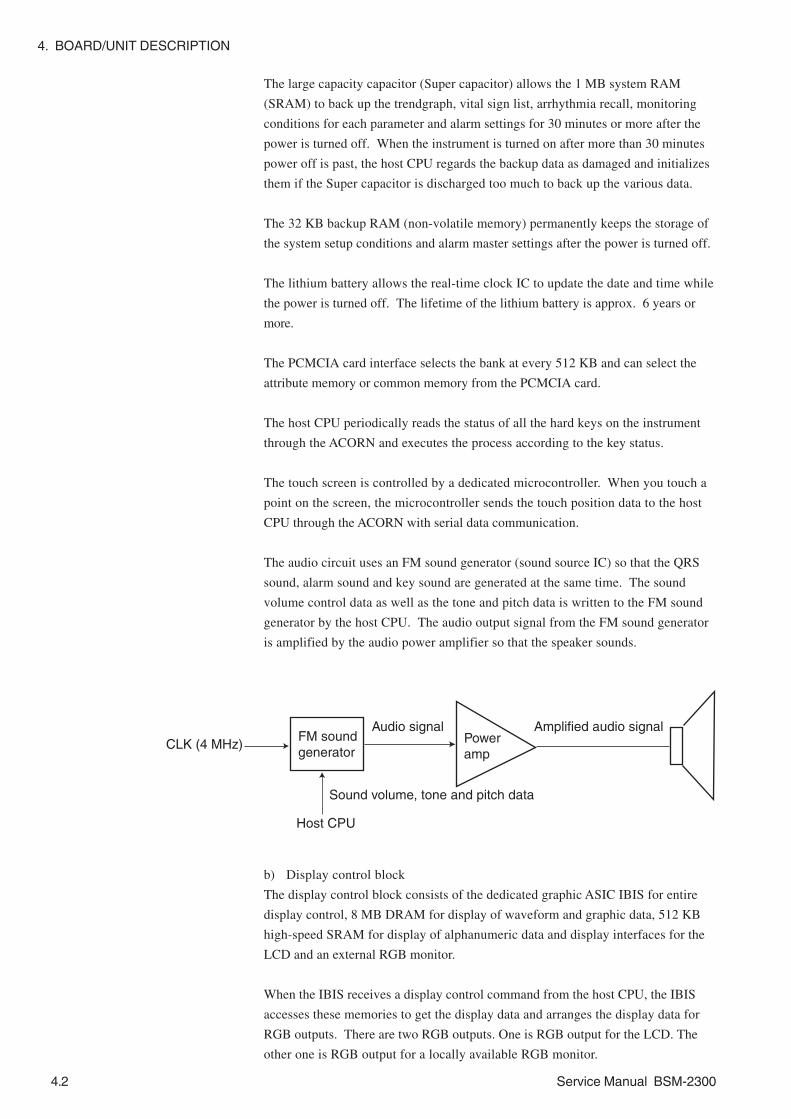
4. BOARD/UNIT DESCRIPTION
4.2 Service Manual BSM-2300
The large capacity capacitor (Super capacitor) allows the 1 MB system RAM
(SRAM) to back up the trendgraph, vital sign list, arrhythmia recall, monitoring
conditions for each parameter and alarm settings for 30 minutes or more after the
power is turned off. When the instrument is turned on after more than 30 minutes
power off is past, the host CPU regards the backup data as damaged and initializes
them if the Super capacitor is discharged too much to back up the various data.
The 32 KB backup RAM (non-volatile memory) permanently keeps the storage of
the system setup conditions and alarm master settings after the power is turned off.
The lithium battery allows the real-time clock IC to update the date and time while
the power is turned off. The lifetime of the lithium battery is approx. 6 years or
more.
The PCMCIA card interface selects the bank at every 512 KB and can select the
attribute memory or common memory from the PCMCIA card.
The host CPU periodically reads the status of all the hard keys on the instrument
through the ACORN and executes the process according to the key status.
The touch screen is controlled by a dedicated microcontroller. When you touch a
point on the screen, the microcontroller sends the touch position data to the host
CPU through the ACORN with serial data communication.
The audio circuit uses an FM sound generator (sound source IC) so that the QRS
sound, alarm sound and key sound are generated at the same time. The sound
volume control data as well as the tone and pitch data is written to the FM sound
generator by the host CPU. The audio output signal from the FM sound generator
is amplified by the audio power amplifier so that the speaker sounds.
CLK (4 MHz)FM soundgenerator
Audio signalPower amp
Amplified audio signal
Sound volume, tone and pitch data
Host CPU
b) Display control block
The display control block consists of the dedicated graphic ASIC IBIS for entire
display control, 8 MB DRAM for display of waveform and graphic data, 512 KB
high-speed SRAM for display of alphanumeric data and display interfaces for the
LCD and an external RGB monitor.
When the IBIS receives a display control command from the host CPU, the IBIS
accesses these memories to get the display data and arranges the display data for
RGB outputs. There are two RGB outputs. One is RGB output for the LCD. The
other one is RGB output for a locally available RGB monitor.

4. BOARD/UNIT DESCRIPTION
Service Manual BSM-2300 4.3
Host CPU IBIS LCD
Graphic DRAM8 MB
Character SRAM512 KB
c) DPU block
The DPU block has the DPU (H8S/2633 microcontroller) which works with 20
MHz clock. The DPU (Data Processing Unit) communicates with the floating
amplifiers and ZB-900P transmitter interface on the Analog board and with the
NIBP board. The DPU acquires the various data from these communications and
processes the data to communicate with the host CPU. The DPU periodically
writes the processed data into the system RAM on the main bus so that the data
communication between the DPU and host CPU is done through the system RAM.
There are 256 KB flash EEPROM and 16 KB SRAM in the DPU. When the
software is upgraded, the host CPU replaces the current program in the flash
EEPROM with the new one in serial data communication.
System Control Block
Host CPU
DPUSystemRAM
Buffer
Data flow in normal operation
Program data flow in upgrade(Serial data communication)
DPU Block
Main bus Local bus
Bus request signal

4. BOARD/UNIT DESCRIPTION
4.4 Service Manual BSM-2300
d) Power control block
The power control block consists of the power supply microcontroller, DC to DC
converters, buzzer and its driver and battery interface.
+15 V from the power supply unit or +12 V from the rechargeable battery is
converted to +3.3 V and +5 V supply voltages by the DC to DC converters and
power supply microcontroller.
When the line voltage is supplied to the instrument and the battery is inserted into
the instrument, the power supply microcontroller charges the battery with approx.
370 mA (normal charge) for 16 hours (maximum). After the normal charging, the
controller uses trickle charging to charges the battery with approx. 370 mA for 1.2
seconds at interval of 1 minute so that the fully charged battery condition is
maintained.
If the normal or trickle charging is interrupted for five hours or less by power
failure or disconnection of the power cord and the battery is not removed from the
instrument, the controller memorizes how many hours the battery is charged before
the interruption. After it is removed, the controller charges the battery under the
memorized condition to protect the battery against excessive charge.
+15 V (AC operation) or+12 V (Battery operation)
Power Control Block
+3.3 V for Host CPU
+5 V for Peripherals
to BatteryPower Switch

4. BOARD/UNIT DESCRIPTION
Service Manual BSM-2300 4.5
The Analog board consists of the ECG/RESP block, SpO2 block, MP block and ZB-
900P interface block. The ECG/RESP block, SpO2 block and MP block are
electrically isolated from the ground, so these blocks are in the floating area. The
ZB-900P interface block is not electrically isolated from the ground so this block
is in the non-floating area. The vital sign input signals are digitized with the A to
D converters in the floating area as shown below. Especially, the process such as
calculation for the SpO2 data is done in the floating area and the SpO2 data goes to
the DPU on the MAIN board through the non-floating area.
Analog Board
TEMP
MP
SpO2
A to D converterA to D
converteror MP-506*
APU
PowerSupply
Trans-former
Optical isolation
ECG
RESP
A to D converter ERC
PowerSupply
Trans-former ZB-900P
DPU
* BSM-2304A/2354A use MP-506 Nellcor SpO2 unit.
ECG/RESP Block There is a dedicated microcontroller ERC (PIC16C63A) in the ECG/RESP block.
This ERC (ECG/Resp Controller) communicates with the DPU and controls the A
to D converter and selects the time constant and filter settings.
The ECG circuit has two individual amplifiers, time constant setting circuits and
hum and low pass filter setting circuits so that two lead ECG waveforms selected
from the eight ECG leads (I, II, III, aVR, aVL, aVF and 2 chest leads) are
simultaneously displayed on the screen when 6-wire type disposable electrode
lead is used.
The impedance method respiration circuit also is in this block. The constant
current generator (exciter) and impedance change detection circuits are included.
The voltage proportional to the impedance change (including the electrode
contact impedance) between the two electrodes for the pickup is multiplexed and
digitized in this block.

4. BOARD/UNIT DESCRIPTION
4.6 Service Manual BSM-2300
Buffer&
MPX
Filter
Time constant
Pacing pulse detection circuit
MPX A to DConverter
ERCTime constant
Filter
Filter
Filter
In these blocks including the temperature block, there is a dedicated
microcontroller APU (H8S/2633) which works with 20 MHz clock. The APU
(Analog-block Processing Unit) communicates with the DPU and controls the
respective A to D converters and executes each data processing for SpO2,
temperature and the other vital sign such as blood pressure connected to the multi-
parameter socket.
There is a flash EEPROM in the APU. When the software is upgraded, the host
CPU replaces the current program in the flash EEPROM with the new one.
SpO2 Block
This block has the following circuits.
• Differential amplifier: Amplifies the electrical signals detected by the
photodiode when the red LED and infrared LED in the SpO2 probe alternatively
transmits the lights to the subject.
• R-IR separator: Separates the electrical signals caused by the red LED and
infrared LED transmissions to the subject.
• Pulse wave amplifier: Amplifies the red LED and infrared LED pulse waves.
• Multiplexer: Multiplexes the analog signals such as pulse waves.
• LED drive current control: Controls the drive currents for the red LED and
infrared LED.
• Probe ID recognition: Detects the probe ID and sends the status data to the APU.
• Probe failure detector: Detects the short circuit in the probe and sends the status
data to the APU.
The APU controls the SpO2 block totally and calculates the SpO2 data from the
various data digitized by the A to D converter (in BSM-2301A/C/K, BSM-2303C/
K, BSM-2351A/C/K and BSM-2353C/K) or receives the SpO2 data from the MP-
506 Nellcor SpO2 unit (in BSM-2304A/2354A).
SpO2 and MP Blocks

4. BOARD/UNIT DESCRIPTION
Service Manual BSM-2300 4.7
SpO2 probe
Differential amp
Pulse wave amp
LED driver
Probe ID recognition
Probe failure detector
R-IR separator
Time division multiplexer
LED controlLight intensity controlGain control
SpO2 status signal
A to D converter
APU(H8S/2633)
MP-506*
* In BSM-2304A/2354A, the MP-506 Nellcor SpO2 unit replaces the block surrounded by a dotted border.
MP Block
The MP block consists of the blood pressure amplifier circuit, thermistor method
respiration circuit and temperature block. The APU recognizes which sensor/
transducer is connected to the multi-parameter socket and selects the exciter
voltage. When the CO2 sensor is connected to the socket, the APU communicates
with the CO2 sensor
The APU receives the digital data from the A to D converter every 2 ms and sends
the data to the DPU.
Temperaturejack
Multi-parameter
socket
Body temperatureamp
Blood pressureamp
Thermistor method respiration amp
Exciter voltage selector
MPX A to D converter APU(H8S/2633)

4. BOARD/UNIT DESCRIPTION
4.8 Service Manual BSM-2300
BSM-2301 and BSM-2351 have no IBP Board.
The IBP board has the input block for invasive blood pressure measurement. This
board consists of the exciter voltage generator and input amplifier. The amplified
blood pressure signal is sent to the multiplexer and A to D converter of the MP
block in the floating area on the Analog board. The digitized data of the blood
pressure signal is sent to the microcontroller APU on the Analog board.
IBP Board
PRESS1 socket
Low-pass filter
Amp
x 195.3 (Gain)
Wire beaking detector
Exciter voltage generatorEXT_2
Connects to CN601 on the Analog board
IBP2_CHK
IBP2

4. BOARD/UNIT DESCRIPTION
Service Manual BSM-2300 4.9
The NIBP board has the pressure sensor for NIBP measurement to detect the cuff
pressure and convert it to an electrical signal. There is no adjustment which can be
done locally.
A microcontroller for safety control, pressure sensor for safety, solenoid valve,
pump and power supply cut-off circuit for the valve and pump are on the NIBP
board. The cuff pressure is individually monitored by this safety circuit and the
DPU on the MAIN board. If a wrong operation such as excessive cuff inflation
caused by the faulty MAIN board or the faulty measurement circuit on the NIBP
board occurs, the safety circuit on the NIBP board provides the multi safety
functions so that the patient is protected from the wrong operation.
If the microcontroller works for the safety, the drive voltage is not supplied to the
pump and valve for 30 sec. This prevents the cuff from inflating during this
period.
Since the measurement data from the measurement circuit and safety circuit are
compared and the operation of the safety circuit is always monitored, the “Safety
Circuit Error” status message immediately appears on the screen if the NIBP
measurement has something wrong.
NIBP Board
HallIC
NIBPsocket
Hall sensorboard
Exciter
Pressure sensor
Ampoffsetadj.
Pulse complex detector
DC amp
Gain controlMPX
Microcontroller
Pump and valve power supply
Pump drive circuit
Valve drive circuit
Pump
Valve
Exciter
Pressure sensor
Ampoffsetadj.
A to D
+15 V
+6 V
To MAIN baord

4. BOARD/UNIT DESCRIPTION
4.10 Service Manual BSM-2300
The power supply block consists of the power supply unit (+15 V DC output), rear
chassis, fuse holder built-in type AC inlet socket, ground terminal and line
frequency detection coil. Refer to Section 8 “REPLACEABLE PARTS LIST”.
This power supply unit same as in the BSM-1101/1102, BSM-4100 series and
WEP-4204/4208 is used.
Power Supply Block

4. BOARD/UNIT DESCRIPTION
Service Manual BSM-2300 4.11
8.4/10.4 inch TFT color LCD which has 800 dots × 600 dots (SVGA) is used as the
display. This LCD unit can display maximum 512 colors. 12 colors can be
assigned for waveforms and each vital sign parameter by the user.
Since the LCD unit is covered with a polarization filter which is weak against an
impact and pressure, it requires your attention during service.
The LCD unit has two cold cathode tubes to backlight the LCD. The high voltage
for the two tubes is supplied from the inverter board.
It takes approx. 50,000 hours (about 5 years and 9 months) for the brightness to
decrease from maximum to half brightness (lifetime of the backlight) if the two
tubes at the maximum brightness work in continuous operation. Therefore, the
tube may need to be replaced after 50,000 hours of use.
LCD Unit

4. BOARD/UNIT DESCRIPTION
4.12 Service Manual BSM-2300
The recorder module has the REC MAIN board and recorder unit as shown below.
The REC MAIN board has the CPU (20 MHz MC68SEC000), 1 MB system ROM
for program storage, 512 KB system RAM for the CPU working area and a
dedicated recorder control ASIC RACOON.
The CPU on this board communicates with the host CPU on the MAIN board
through the RACOON. The RACOON controlled by the CPU on this board
controls all the recording functions such as the paper drive motor control and
thermal array head control.
When the instrument is upgraded, the bus on this board is directly connected to the
main bus on the MAIN board and the 1 MB system ROM takes a part of the
memory for the upgrade program. The host CPU replaces the previous program in
the 1 MB system ROM with the new one.
Recorder Module (Option)
REC MAIN Board
MAIN Board REC MAIN Board
Host CPU CPU
ROM RAM
RACOON I/O
Data flow in normal operation
RACOON
Program data flow in upgrade
Main bus Local bus

4. BOARD/UNIT DESCRIPTION
Service Manual BSM-2300 4.13
The recorder unit consists of thermal array head, paper drive motor, gears, recorder
chassis, sensor board (paper and mark detectors included) and sensor control board.
The RACOON (ASIC) on the REC MAIN board allows the recorder unit to record
the 3 channel waveforms, vital sign list and trendgraph.
Since the thick membrane type thermal array head is used, it does not require the
adjustment of the supply voltage to the head. The lifetime of the heating elements
on the head is 100 million heating times.
A stepping pulse motor is used as the paper drive motor. The lifetime of the motor
is approx. 3,000 hours continuous operation.
When the paper detector or mark detector (LED and phototransistor assembly) on
the sensor board is replaced with a new one, the gain control VR on the sensor
control board must be adjusted. See Section 7 “ADJUSTMENT”.
Recorder Unit

4. BOARD/UNIT DESCRIPTION
4.14 Service Manual BSM-2300
The interface has the IO ANALOG OUT board inside. This board consists of the
following three blocks.
Interface (Option, QI-231P)
Pho
to
coup
ler
Non
-flo
atin
g ar
ea
EC
G o
r tr
igge
r di
gita
l sig
nal
RG
BS
eria
l dat
a co
mm
unic
atio
n
+5
V s
uppl
y vo
ltage
20-p
in A
UX
soc
ket f
or
seria
l dat
a co
mm
unic
atio
n
15-p
in R
GB
out
put s
ocke
t
128
kHz
osci
llato
rT
rans
form
er5
VF s
uppl
y vo
ltage
Flo
atin
g ar
ea
To
the
AU
X s
ocke
t on
the
BSM
-230
0 se
ries
Mic
ro-
cont
rolle
r12
bit
D to
A
conv
erte
rF
ilter
Ana
log
switc
hE
xces
sive
vo
ltage
pr
otec
tion
circ
uit
EC
G o
r tr
igge
r ou
tput
TR
IG/E
CG
jack
4 M
Hz
osci
llato
rB
it se
tting
for
EC
G o
utpu
ts00
00: E
CG
HU
M1
0001
: EC
G1
0010
: EC
GH
UM
200
11: E
CG
2
Trig
ger
outp
utci
rcui
tE
CG
and
tr
igge
r ou
tput
LE
D in
dica
tors
4-bi
t sw
itch
ON
: 1O
FF
: 0

4. BOARD/UNIT DESCRIPTION
Service Manual BSM-2300 4.15
Data of the ECG, QRS synch or alarm trigger signal from the AUX socket of the
bedside monitor are sent to the floating area of the board through the photo
coupler. In the floating area, the data are sent to the microcontroller
(PIC16C63A) which communicates with the bedside monitor, selects the output
signal with the analog switch, controls the D to A converter, selects the ECG1
or ECG2 with or without hum filter according to the 4-bit switch setting and
lights the ECG or TRIG LED. When the ECGHUM1 is selected, the hum filtered
ECG1 analog signal from the D to A converter goes to the output jack.
The current software does not support this communication.
When an external device which has an RS232C port is connected to the
RS232C socket on this board, the serial data will be communicated between the
external device and bedside monitor through this board if the same
communication protocol is used between the external device and bedside
monitor.
The RGB analog signals are sent to the RGB output socket on this board
through the AUX socket of the bedside monitor.
ECG, QRS Synch or AlarmTrigger Signal OutputBlock
Serial Data CommunicationRelay Block
RGB Relay Block

4. BOARD/UNIT DESCRIPTION
4.16 Service Manual BSM-2300
Interface (Option, QI-236P)
The interface has the IO CT OUT board inside. This board consists of the following
two blocks.
RG
B
M
icro
-
con
trol
ler
PIC
16C
63A
(PIC
1)
12-b
it D
to A
con
verte
r
M
icro
-
cont
rolle
r P
IC16
C63
A
(P
IC2)
4 M
Hz
osci
llato
r
EC
G
HT
RG
B
EC
G
Ded
icat
ed s
eria
l dat
aco
mm
unic
atio
n be
twee
n B
SM
-230
0 an
d Q
I-23
6P
+5 V
+
4 M
Hz
osci
llato
r
Sen
sitiv
ity s
elec
tor
Full-
wav
e r
ectif
ier
Filte
rC
ompa
rato
r
Am
pFi
lter
Tra
nsfo
rmer
5 V
F s
uppl
y vo
ltage
T
-wav
edi
scrim
inat
or
128
kHZ
osci
llato
r

4. BOARD/UNIT DESCRIPTION
Service Manual BSM-2300 4.17
Data of the ECG signal from the AUX socket of the bedside monitor are sent to
the microcontroller (PIC16C63A:PIC1) which controls the D to A converter.
The data from the D to A converter goes to two circuits. One is the QRS detection
circuit. This signal is output as the QRS synch trigger signal “HT”. The “HT”
signal is sent to the microcontroller (PIC16C63A:PIC2) which communicates with
the bedside monitor. The other is a filtered ECG analog signal which goes to the
output connector as “ECG”.
The RGB analog signals are sent to the RGB output socket on this board
through the AUX socket of the bedside monitor.
ECG and QRS SynchTrigger Signal OutputBlock
RGB Relay Block

4. BOARD/UNIT DESCRIPTION
4.18 Service Manual BSM-2300
This page is intentionally left blank.

Service Manual BSM-2300 5C.1
Section 5 Disassembly andAssembly
Removing the Chassis Block ..............................................................................................5.1
Replacing the MAIN Board ..................................................................................................5.6
Replacing the Analog Board .............................................................................................. 5.10
Replacing the NIBP Board ................................................................................................. 5.12
Replacing the IBP Board ................................................................................................... 5.14
Replacing the Inverter Board (BSM-2301/2303/2304) ........................................................ 5.15
Replacing the Inverter Board and Inverter IF Board (BSM-2351/2353/2354) ..................... 5.17
Replacing the LCD Unit (BSM-2301/2303/2304) ................................................................ 5.19
Replacing the LCD Unit (BSM-2351/2353/2354) ................................................................ 5.21
Replacing the LCD IF Board (BSM-2351/2353/2354) ......................................................... 5.23
Replacing the Backlight Lamp Unit (BSM-2301/2303/2304) ............................................... 5.24
Replacing the Backlight Lamp (BSM-2351/2353/2354) ...................................................... 5.26
Replacing the Lithium Battery ........................................................................................... 5.28
Replacing the Battery Pack ............................................................................................... 5.29
When the Recorder Module is Not Attached to the Instrument ................................ 5.29
When the Recorder Module is Attached to the Instrument ...................................... 5.31
Replacing the IO ANALOG OUT or IO CT OUT Board of the Optional Interface ............... 5.33

5. DISASSEMBLY AND ASSEMBLY
Service Manual BSM-2300 5.1
CAUTION••••• Turn off the instrument and disconnect the power cord from the
instrument before beginning the disassembly procedure.
••••• Before placing the instrument on a table, if its surface is dirty, hard or
rough, cover the table with a clean, soft and smooth material to avoid
making the screen dirty and damaging the screen.
1. Place the instrument face down on the table as shown below.
Removing the Chassis Block
<When the recorder module is not attached to the instrument>
2-1a. Remove the 3 screws from the bottom of the instrument with a long Phillips
screwdriver. Separate the battery box (enclosure) from the instrument and
put the battery box close to the instrument because the battery cable is
connected to the battery pack in the battery box.
2-1b. Disconnect the battery pack from the battery cable and remove the battery
box from the instrument.
<When the recorder module is attached to the instrument>
2-2a. Remove the 3 screws from the bottom of the recorder module with a long
Phillips screwdriver. Refer to the figure in step 2. Separate the recorder
module from the instrument and put the recorder module close to the
instrument because the battery cable and two flat cables are connected
between the recorder module and instrument.

5. DISASSEMBLY AND ASSEMBLY
5.2 Service Manual BSM-2300
2-2b. Gently pull the battery cable until the connectors come out from the
recorder module.
2-2c. Disconnect the battery cable from the battery pack of the recorder module.
2-2d. Press the latches at both ends of the upper flat cable connector to release the
lock and disconnect the upper flat cable from the instrument. Press the
latches at both ends of the lower flat cable connector to release the lock and
disconnect the lower flat cable from the instrument. Remove the recorder
module from the instrument.
NOTE in Assembling the InstrumentWhen connecting the two flat cables to the instrument, check the
direction of the connector and insert it into the socket of the instrument
until the connector clicks. Check that the longer flat cable is connected
to the upper socket of the instrument.
3. Remove the 5 screws from the rear enclosure and remove the rear enclosure
from the instrument as shown below. The rear chassis appears.
NOTE in Assembling the InstrumentWhen attaching the rear enclosure to the instrument, be careful not to
pinch or strain the internal wires or cables and tubes.
Latches

5. DISASSEMBLY AND ASSEMBLY
Service Manual BSM-2300 5.3
4. Remove the 2 screws from the left and right side panels and remove them from
the chassis block.
<Right side> <Left side>
5. Disconnect the 4 cables as shown below.
CAUTION••••• To disconnect the touch screen cable (film cable), pull up the black
flange of the socket on the MAIN board so that the cable is set free.
••••• Before disconnecting the touch screen cable (film cable), wear gloves
to protect the film cable from fingerprints and any damage.
••••• When connecting the touch screen cable (film cable) to the socket,
check that the flange is set to the original position after the cable is
properly inserted into the socket.
BSM-2301 and BSM-2351 have no PRESS1 socket.
BSM-2304A and BSM-2354A have Nellcor SpO2
socket instead of NK SpO2 socket.
Touch Screen Cable
Photo shows BSM-2351/2353/2354
Filament tape

5. DISASSEMBLY AND ASSEMBLY
5.4 Service Manual BSM-2300
6. Remove the 10 screws from the chassis block as shown below.
<Top side> <Bottom side>
<Right side> <Left side>
7. Slightly lift the chassis block and disconnect the inverter board cable from the
chassis block.
Screw with washer

5. DISASSEMBLY AND ASSEMBLY
Service Manual BSM-2300 5.5
8. Separate the front enclosure from the chassis block.
9. Remove the speaker holder from the rear chassis by gradually swinging the
speaker holder rightward and leftward.
NOTE in Assembling the InstrumentCheck that the speaker wires come out at the top of the speaker holder.
Speaker wires

5. DISASSEMBLY AND ASSEMBLY
5.6 Service Manual BSM-2300
Perform the following procedure after the “Removing the chassis block”
procedure.
1. Remove the 5 screws (two M2 screws included) which secure the MAIN board
as shown below.
Replacing the MAIN Board
2. Slightly lift the MAIN board as shown below and separate the connector on
the MAIN board from the connector on the Analog board.
Two M2 screws

5. DISASSEMBLY AND ASSEMBLY
Service Manual BSM-2300 5.7
3. Pull the MAIN board holder outward as shown below and pull the tab of the
MAIN board upward to remove the tab from the slot.
4. Put the MAIN board beside the chassis block and disconnect the power cable
and NIBP cable from the MAIN board.
Power cable
NIBP cable

5. DISASSEMBLY AND ASSEMBLY
5.8 Service Manual BSM-2300
5. Remove the 7 screws (marked with circles in the following picture) from the
MAIN board and remove the shield cover from the MAIN board.
NOTEDo not remove the 4 screws marked with X which secure the PCMCIA
card slot socket.

5. DISASSEMBLY AND ASSEMBLY
Service Manual BSM-2300 5.9
CAUTION in Assembling the Instrument••••• Hold the battery cable with the cable clamp of the MAIN board holder
and pass the battery cable through the MAIN board holder as shown
below.
••••• Before fitting the MAIN board into the chassis block, insert the tab of
the MAIN board into the slot of the MAIN board holder.
••••• To fit the MAIN board into the chassis block, align the connector on
the MAIN board with the connector on the Analog board and press the
MAIN board around the connector onto the Analog board. Check that
the connection between the boards is complete.
Cable clamp
MAIN board holder
Cable clamp
Slot

5. DISASSEMBLY AND ASSEMBLY
5.10 Service Manual BSM-2300
Perform the following procedure after the “Replacing the MAIN Board” procedure
step 4.
1. Remove the 3 screws (marked with circles in the following picture) which
secure the Analog board to the chassis block.
NOTEIf the 3 screws are left in the holes, it may be difficult to slide the Analog
board.
Replacing the Analog Board
ZB socket
2. Slide the Analog board in the direction of the arrow in the picture below to
avoid obstruction of the ZB socket and remove the Analog board from the
chassis block.
In case of BSM-2303/2304/2353/2354, Disconnect the connection cable
which connects between the Analog board and IBP board.

5. DISASSEMBLY AND ASSEMBLY
Service Manual BSM-2300 5.11
The BSM-2304A and BSM-2354A monitor have the MP506 Oximax pulse
oximetry module which is attached to the Analog board. When replacing this
module with a new one, check that the settings of the DIP switch SW1 on the new
module are correct and that the pin protector is removed from the new module.
Refer to Section 8 “Replaceable Parts List”.
Since a pin protector is attached to this socket, remove the pin protector
from the socket. Otherwise, the module cannot be attached to the Analog
board.
A wrong setting disables SpO2 measurement and an “SpO2 Module Error”
message will be displayed on the screen.
DIP switch SW1
No. 1 2 3 4Setting OFF ON ON OFF

5. DISASSEMBLY AND ASSEMBLY
5.12 Service Manual BSM-2300
Perform the following procedure after the “Replacing the Analog Board”
procedure.
1. Disconnect the NIBP cable and line frequency detection wire from the NIBP
board.
2. Remove the 4 screws (marked with circles in the following picture) which
secure the NIBP board to the chassis block.
Replacing the NIBP Board
NIBP cable
Line frequency
detection wire
3. Remove the spacer bolt from the NIBP board and remove the NIBP board from
the chassis block. Spacer bolt

5. DISASSEMBLY AND ASSEMBLY
Service Manual BSM-2300 5.13
To prevent the pump holder from coming off, there is a rubber lock inserted into
the one-side feet of the NIBP pump holder on the underside of the NIBP board as
shown below.
When replacing the NIBP board with a new one, check that the rubber locks are
inserted into the same position on the new NIBP board as the old one. Since the
rubber locks are not included in NIBP board, the rubber locks are separately
available if new rubber locks are necessary.
NK parts code: 6114-131066

5. DISASSEMBLY AND ASSEMBLY
5.14 Service Manual BSM-2300
Replacing the IBP Board
BSM-2301 and BSM-2351 have no IBP board.
Perform the following procedure after the “Replacing the NIBP Board” procedure.
1. Remove the 2 screws (marked with circles in the following figure) which
secure the IBP board to the NIBP board. Remove the IBP board from the NIBP
board.
2. Remove the 2 screws which secure the holder to the IBP board. Remove the
IBP board from the holder.

5. DISASSEMBLY AND ASSEMBLY
Service Manual BSM-2300 5.15
Perform the following procedure after the “Removing the Chassis Block”
procedure.
1. Disconnect the backlight lamp cable from the cable of the inverter board.
CAUTIONSince the pin terminals of the connector may be removed if you pull the
backlight lamp cable, you must pull the connector housing for the cable
disconnection. If a pin terminal is removed from the connector, you
must replace the cable with a new one.
Replacing the Inverter Board (BSM-2301/2303/2304)
2. Remove the 3 screws which secure the inverter board with the top chassis to
the front enclosure and remove the inveter board and the top chassis from the
front enclosure.

5. DISASSEMBLY AND ASSEMBLY
5.16 Service Manual BSM-2300
3. Remove the 2 screws which secure the inverter board to the top chassis and
remove the inverter board from the top chassis.

5. DISASSEMBLY AND ASSEMBLY
Service Manual BSM-2300 5.17
Replacing the Inverter Board and Inverter IF Board
(BSM-2351/2353/2354)
1. Disconnect the 2 cables of the backlight lamp at the inverter IF board.
NOTE in Assembling the InstrumentYou can connect the two cables to either sockets on the inverter IF
board.
2. Remove the 4 screws marked with circles in the following picture. Remove the
inverter board, inverter IF board and board holder from the front enclosure.
Perform the follwing procedure after the “Removing the Chassis Block” procedure.

5. DISASSEMBLY AND ASSEMBLY
5.18 Service Manual BSM-2300
3. Remove the 2 screws marked with circles in the following picture and remove
the inverter board from the board holder.
4. Remove the spacer bolt and screw marked with circles in the following picture.
Remove the inverter IF board from the board holder.

5. DISASSEMBLY AND ASSEMBLY
Service Manual BSM-2300 5.19
Perform the following procedure after the “Replacing the Inverter Board (BSM-
2301/2303/2304)” procedure step 2.
1. Remove the 6 screws which secure the LCD unit with the holder to the front
enclosure and remove the LCD unit and the holder from the front enclosure.
Replacing the LCD Unit (BSM-2301/2303/2304)
CAUTION••••• If the LCD unit is adhered to the touch screen of the front enclosure,
carefully peel the touch screen off from the edges to the center.
••••• Since the touch screen is covered with glass, do not apply excessive
mechanical shock such as dropping or pressure to the touch screen.
••••• Pay attention to the sharp glass parts such as the touch screen edges.
It can cause cuts and injuries.
Front enclosure
Touch screen

5. DISASSEMBLY AND ASSEMBLY
5.20 Service Manual BSM-2300
2. Remove the 4 screws which secure the LCD unit to the holder and remove the
LCD unit from the holder.

5. DISASSEMBLY AND ASSEMBLY
Service Manual BSM-2300 5.21
Replacing the LCD Unit (BSM-2351/2353/2354)
Perform the following procedure after the “Replacing the Inverter Board and
Inverter IF board (BSM-2351/2353/2354) procedure step 2.
1. Remove the filament tape which covers the touch screen cable.Remove the 10
screws marked with circles in the following picture. Remove the metal fitting
for the ferrite core of the cable between the MAIN board and LCD IF board.
CAUTION in Assembling the InstrumentTo prevent the cable between the Operation and MAIN boards from
being damaged at the metal edge of the new LCD unit, attach a vinyl
tape such as filament tape around the edge of the LCD unit. For the
proper tape position, see the old LCD unit. Before taping, clean the tape
position with alcohol.
Filament tape and
metal fitting for ferrite core
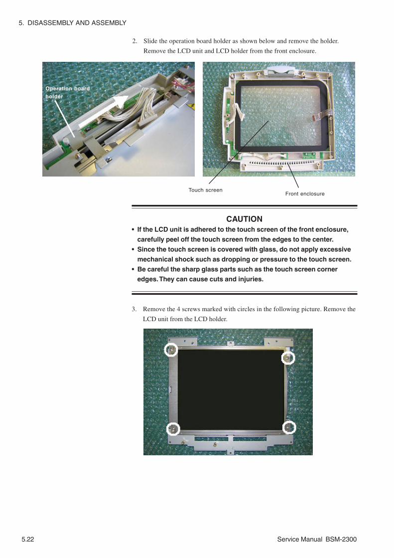
5. DISASSEMBLY AND ASSEMBLY
5.22 Service Manual BSM-2300
2. Slide the operation board holder as shown below and remove the holder.
Remove the LCD unit and LCD holder from the front enclosure.
CAUTION• If the LCD unit is adhered to the touch screen of the front enclosure,
carefully peel off the touch screen from the edges to the center.
• Since the touch screen is covered with glass, do not apply excessive
mechanical shock such as dropping or pressure to the touch screen.
• Be careful the sharp glass parts such as the touch screen corner
edges. They can cause cuts and injuries.
3. Remove the 4 screws marked with circles in the following picture. Remove the
LCD unit from the LCD holder.
Operation board
holder
Touch screenFront enclosure

5. DISASSEMBLY AND ASSEMBLY
Service Manual BSM-2300 5.23
Replacing the LCD IF Board (BSM-2351/2353/2354)
Remove the LCD IF board from the LCD unit after the “Replacing the LCD Unit”
procedure.
LCD IF board
CAUTION in Assembling the InstrumentTo connect the LCD IF board to the LCD unit, align the connectors of the
LCD unit and LCD IF board and firmly press the LCD IF board until it
clicks.

5. DISASSEMBLY AND ASSEMBLY
5.24 Service Manual BSM-2300
Perform the following procedure after the “Replacing the LCD Unit (BSM-2301/
2303/2304)” procedure.
1. Place the LCD unit face down on the table covered with a clean, soft and
smooth material.
2. Remove the screw marked with arrow 1 in the following picture.
3. Peel off the conductive tape marked with arrow 2 in the following picture.
CAUTION••••• Since the LCD unit and lamps in the backlight lamp unit are covered
with glass, do not apply a mechanical shock such as dropping or
pressure to them.
••••• If a lamp in the backlight lamp unit has a small crack, the gas
composition in the lamp will gradually change and the characteristics
may deteriorate too much in a short period.
••••• Do not strain the cable of the backlight lamp unit.
••••• Check that the cables between the inverter board and backlight lamp
unit are not damaged. If a cable has even slight damage, it may break
the vinyl of the wire and short circuit may occur because a high
voltage is output for the lamps through the cable.
••••• Carefully handle the edges of the backlight lamp unit and holding
plate because their edges are sharp and can cause cuts and injuries.
Replacing the Backlight Lamp Unit (BSM-2301/2303/2304)
1 2

5. DISASSEMBLY AND ASSEMBLY
Service Manual BSM-2300 5.25
4. Lift the backlight lamp unit at the cable side as shown below and pull the
lamp unit in the direction of the arrow in the picture.
5. Replace the lamp unit with a new one and insert the tab of the lamp unit into
the groove marked with the circle in the following picture.
6. Fasten the lamp unit with the screw. It requires approximately 1.5 kgf torque
with a torque controllable screwdriver.

5. DISASSEMBLY AND ASSEMBLY
5.26 Service Manual BSM-2300
Replacing the Backlight Lamp (BSM-2351/2353/2354)
Perform the following procedure after the “Replacing the LCD Unit (BSM-2351/2353/
2354)” procedure.
1. Put the LCD unit face down on a table covered with a clean, soft and smooth
material.
CAUTION• Since the LCD unit and backlight lamp are glass, do not apply a
mechanical shock such as dropping or pressure to them. If the
backlight lamp gets even a small crack, the gas composition in the
lamp will gradually change and the characteristics may deteriorate too
much in a short period.
• Do not strain the cable of the backlight lamp.
• Check that the cables of the backlight lamp are not damaged. If a
cable has even slight damage, it may break the vinyl of the wire and
short circuit may occur because a high voltage is output to the lamps
through the cable.
• Dispose of used backlight lamps according to your local laws because
fluorescent material is used.
2. Remove the connector marked with a circle in the following picture by using a
flat-blade screwdriver.

5. DISASSEMBLY AND ASSEMBLY
Service Manual BSM-2300 5.27
3. Remove the backlight lamp from the LCD unit as shown with the arrow.

5. DISASSEMBLY AND ASSEMBLY
5.28 Service Manual BSM-2300
Perform the following procedure after the “Replacing the MAIN Board” procedure.
1. Replace the lithium battery on the MAIN board with a new one as shown
below.
After the battery replacement, check the continuity between the battery
terminal and receptacle terminal with a multimeter.
CAUTION••••• Use a glove to handle the new lithium battery. If you touch it with your
bare hand, it may cause an increase of resistance at the battery
terminals and shorten the lifetime.
••••• Never charge, short-circuit, disassemble, deform, heat, or throw the
battery into fire. This may cause overheating, explosion, or fire.
••••• Before disposing of the battery, cover it with insulation tape to prevent
short circuit between the positive and negative terminals. Otherwise,
the battery may heat, explode or burn if the battery is disposed of with
other batteries or electrically conductive materials.
••••• Discard used batteries according to your local laws.
Replacing the Lithium Battery

5. DISASSEMBLY AND ASSEMBLY
Service Manual BSM-2300 5.29
CAUTION••••• Turn off the instrument and disconnect the power cord from the
instrument before beginning the procedure.
••••• Before placing the instrument on a table, if its surface is dirty, hard or
rough, cover the table with a clean, soft and smooth material to avoid
making the screen dirty and damaging the screen.
1. Place the instrument face down on the table as shown to the left.
2. Remove the 3 screws from the bottom of the instrument with a long Phillips
screwdriver. Separate the battery box from the instrument and put the battery
box close to the instrument because the battery cable is connected to the
battery pack in the battery box.
3. Disconnect the battery pack from the battery cable and remove the battery
pack from the battery box.
Replacing the Battery Pack
When the Recorder Moduleis Not Attached to theInstrument
Screws
Battery box
Battery cable
Battery pack

5. DISASSEMBLY AND ASSEMBLY
5.30 Service Manual BSM-2300
4. Connect a new battery pack to the battery cable.
5. Install the new battery pack into the original position.
CAUTIONIf the battery pack is incorrectly placed in the space for the battery pack,
the battery pack does not fit the space. To check the position of the
battery pack, check that the direction of the label on the battery pack is
correct.
6. Arrange the cable in the space at the right side of the battery pack as shown
below so that it does not come out.
7. Fasten the battery box to the instrument with the 3 screws.

5. DISASSEMBLY AND ASSEMBLY
Service Manual BSM-2300 5.31
CAUTION••••• Turn off the instrument and disconnect the power cord from the
instrument before beginning the procedure.
••••• Before placing the instrument on a table, if its surface is dirty, hard or
rough, cover the table with a clean, soft and smooth material to avoid
making the screen dirty and damaging the screen.
1. Place the instrument face down on the table as shown below.
When the Recorder Moduleis Attached to theInstrument
Binding head screws
Pan head screws with washer
2. Remove the 2 pan head screws with washer and 2 binding head screws from
the rear and bottom of the recorder module. Remove the bottom plate from the
recorder module.
Bottom plate
Insulation sheet
3. Remove the half transparent insulation sheet from the recorder module.
4. Gently pull the battery pack outward until the cable of the battery pack can be
disconnected from the battery cable.
Battery pack

5. DISASSEMBLY AND ASSEMBLY
5.32 Service Manual BSM-2300
5. Disconnect the battery pack from the battery cable and remove the battery
pack from the recorder module.
6. Connect a new battery pack to the battery cable and arrange the cable as
shown below so that it does not come out.
7. Install the new battery pack into the original position as shown below.
CAUTIONIf the battery pack is incorrectly placed in the space for the battery pack,
the battery pack does not fit the space. To check the position of the
battery pack, check that the direction of the label on the battery pack is
correct.
8. Put the insulation sheet back to the original position as shown below.
9. Fasten the bottom plate to the recorder module with the 4 screws.
Battery cable
Label
Insulation sheet Battery pack
Binding head screws
Pan head screws with washer

5. DISASSEMBLY AND ASSEMBLY
Service Manual BSM-2300 5.33
1. Remove the 6 black screws (QI-231P) or 4 black screws (QI-236P) and
corrugated washers which secure the top cover to the bottom case and side
panel (QI-236P has no side panel). Remove the top cover and side panel
from the bottom case.
2. Remove the screw which secures the earth wire of the AUX connection
cable. Disconnect the 2 connectors of the AUX connection cable from the
board. Loosen the nut which fastens the AUX connection cable to the
bottom case. Remove the AUX connection cable from the bottom case.
Replacing the IO ANALOG OUT or IO CT OUT Board of the
Optional Interface
Nut
Earth wire
Screw

5. DISASSEMBLY AND ASSEMBLY
5.34 Service Manual BSM-2300
3. Remove the 2 pan head screws (QI-231P) or 2 hexagonal head screws (QI-
236P) and the 2 hexagonal head screws which secure the sockets on the
board to the bottom case. Remove the screw which secures the board to
the bottom case.
4. Remove the board from the bottom case.
Pan-head screws (QI-231P)
or Hexagonal head screws (QI-236P) Hexagonal head screws
Screw

Service Manual BSM-2300 6C.1
Section 6 Maintenance
To Be Replaced Periodically ................................................................................................6.1
Required Tools .....................................................................................................................6.1
Measuring and Test Equipment ...........................................................................................6.2
Maintenance Check Items and Schedule ............................................................................6.3
External .....................................................................................................................6.3
Input Conditions ........................................................................................................6.3
Operation ..................................................................................................................6.4
Display ......................................................................................................................6.4
Recorder ....................................................................................................................6.4
Interface ....................................................................................................................6.5
Vital Sign Parameters ................................................................................................6.5
Power ........................................................................................................................6.6
Data Backup .............................................................................................................6.6
Safety .......................................................................................................................6.7
Others .......................................................................................................................6.7

6. MAINTENANCE
Service Manual BSM-2300 6.1
Required Tools
• Long-bladed Phillips screwdriver (insulated) with magnetized tip
• Long-bladed flat screwdriver (insulated) with magnetized tip
• Anti-static bench mat connected to appropriate ground
• Anti-static wrist strap connected to appropriate ground
• 3 mm hex socket driver
• Tweezers
• Nippers
• Cable ties
We recommend the periodic replacement of the following components according
to the expected life span.
To Be Replaced Periodically
NK Code No. Description Expected Life Span616193 Backlight assembly for
LCD unit of BSM-2301/2303/2304
677955 Backlight assembly forLCD unit of BSM-2351/2353/2354
Approx. 50,000 hours or 5years and 9 months or moreof continuous operation
481809(Supply code: X208)
Lithium battery forclock operation backup
Approx. 6 years or more
611893 Battery cushion sponge Approx. 3 years or more6114-120416 Battery cushion sponge Approx. 3 years or more6114-053114C Platen roller Approx. 6 years or more107002 Retainer ring Must be replaced with a new
one when the platen roller isreplaced.
445074 Thermal array head Approx. 250 stacks or moreof the recording paper
445109C Paper drive motor Approx. 6,000 stacks or moreof the recording paper

6. MAINTENANCE
6.2 Service Manual BSM-2300
Measuring and Test Equipment
To repair, check, or adjust the instrument, the following measuring and test
equipment or equipment with similar function and performance is required.
Digital Voltmeter
A digital tester with at least 3-1/2 digits LCD display that can measure voltage,
current, and resistance.
Cathode-ray Oscilloscope
An oscilloscope with a bandwidth of more than 1 MHz and a sensitivity of more
than 10 mV/cm.
Function Generator
A function generator with a range of 1 Hz to at least 1 kHz with 1% or better
frequency accuracy.
AX-800P Vital Sign Simulator
The simulator outputs simulated waveforms, i.e. ECG waveform, respiration curve,
4 blood pressure waveforms, 2 temperature fixed values, and cardiac output curve.
548631A Adapter Cable
Although the simulator has the connection cable for previous bedside monitors
such as BSM-2100/3101/7000/8300/8502/8800, the new bedside monitors such as
BSM-1100/2301/4100/9510 and BSS-9800 require this adapter cable instead of
the previous bedside monitor connection cable.
YS-077P1 NIBP Dummy Cuff
A 700 mL container that is needed for some NIBP check items in the diagnostic
check mode.
YS-077P2 NIBP Dummy Cuff
A 250 mL container that is needed for some NIBP check items in the diagnostic
check mode.
6443-000022B NIBP Dummy Cuff
A 72 mL container that is needed for some NIBP check items in the diagnostic
check mode.
Extension Board
Designed for the maintenance of the boards. The MAIN board and Analog board
can be connected through the extension board.
The extension board consists of the following components.
Printed circuit board: 6190-022193
Connector: 611082
Connector: 611073
These components must be assembled locally.

6. MAINTENANCE
Service Manual BSM-2300 6.3
Maintenance Check Items and Schedule
Perform this maintenance check once every six months.
A maintenance check sheet is provided at the end of this section. Make a copy of
this check sheet before using it. The check items are grouped as follows:
• External
• Input conditions
• Operation
• Display
• Recorder
• Interface
• Vital sign parameters
• Power
• Data backup
• Safety
• Others
Following are the procedures for each check item.
External
Item Check Procedure ActionDirt, stain or crack Check that there is no dirt, stain and
crack on the instrument.If the instrument is dirty, clean it with a clothmoistened with water, neutral soap or alcohol. Ifthe instrument has stain or crack, remove it orreplace the stained or cracked part with a new one.
Damaged switch or keytop cover
Check that there are no physicallydamaged switches and key topcovers.
If any switch or key top cover is damaged, replaceit with a new one.
Input Conditions
Item Check Procedure ActionContact between input socketon the instrument andconnector of connection cord
Check that there is good contactbetween the input socket andconnector of the connection cord.
Remove the cause if there is a poor contactbetween them.
Input socket on theinstrument or connector ofconnection cord
Visually check that there is nodamaged input socket and connector.
If the input socket or connector isdamaged, replace it with a new one.
Electrode lead wire orconnection cord
Visually check that there is no damageof the lead wire and connection cord.
If the electrode lead wire or connectioncord has a damage, replace it with a newone.

6. MAINTENANCE
6.4 Service Manual BSM-2300
Operation
Item Check Procedure ActionKey function on theoperation panel
Check that the function of each key on thecontrol panel works correctly.
Remove the cause if the key function iswrong.
Touch screen keyfunction
Check that the function of each key on thescreen works correctly.
Remove the cause if the key function iswrong.
Display
Item Check Procedure ActionCrack, scratch or dirt Check that there is no crack, scratch or dirt
on the touch screen.If there is a crack or scratch on the screen,replace it with a new one. If the screen is dirty,clean it with a soft cloth moistened with water.
Display controlsettings
Check that the control settings such asbrightness work smoothly.
If one of the control settings has no function,remove the cause.
Minimum brightnesscontrol
Check that the waveforms and data do notdisappear when the brightness is set tominimum on the screen.
Remove the cause if the waveforms or datadisappear from the screen.
CRTC check Check that there is no error on the screenwhen performing the CRTC checks on theManual Check Menu screen.
Remove the cause if an error occurs.
RecorderItem Check Procedure Action
Waveform and characterdata on paper
Check that the waveform and characterdata on the paper are clear.
If the waveform or character data is notclear, clean the thermal array head. Referto the operator’s manual.
Recording paper Check that Nihon Kohden recording paperis used.
If unspecified paper is used, replace it withNihon Kohden specified paper.
Paper drive check Check that the paper moves at a presetpaper speed without snaking.
Remove the cause if the paper movesabnormally.
Abnormal sound Check that the motor and gears do notgenerate abnormal sound.
Remove the cause if there is abnormalsound.
Mark detection Check that the mark detection workscorrectly.
Remove the cause if the mark detectiondoes not work.
Recorder check in WSCheck mode
Check that there is no error on the paperwhen performing the recorder check in theWS Check mode. Refer to Section 3.
Replace the MAIN board or othercomponent with a new one according tothe WS Check Mode section.
Printed date and timecheck
Check that the correct date and time areprinted on the paper.
Remove the cause if the date and time iswrong or not printed.

6. MAINTENANCE
Service Manual BSM-2300 6.5
Vital Sign Parameters
Item Check Procedure ActionWaveform and numericdata
Check that ECG, respiration, bloodpressure waveforms, their parameters andtemperature data are displayed correctlyand QRS synchronous sound is generatedwhen connecting AX-800P vital signsimulator to the instrument.
If there is anything wrong, check theconnection between the AX-800P andinstrument and remove the cause.
SpO2 and NIBP Check that the displays of SpO2 and NIBPparameters are acceptable when applyingthe SpO2 probe and NIBP cuff to a healthyperson or yourself.
If there is a big difference, check theconnection between the healthy person andinstrument and remove the cause.
NIBP check Check that there is no error on the screenwhen performing the NIBP checks on theManual Check Menu screen.
Remove the cause if an error occurs.
Multi-parameter socketfunction
Check that the connection cord isrecognized and the related parameter isdisplayed when connecting the connectioncord to the socket.
If the socket has no function, plug theconnection cord into the other multi-parameter sockets and check which one iswrong, connection cord or instrument.
Zero balance of IBP Check that the blood pressure transducer iszero balanced when connecting thetransducer to the instrument through theIBP connection cord and pressing “ALLZERO” key or multi-parameter key on thescreen.
If the transducer is still imbalanced afterzeroing, connect the transducer to the othermulti-parameter sockets and check whichone is wrong, transducer or instrument.
Alarm function Check that the alarm mark appears on thescreen, the alarm indicator works, and thealarm sounds when an alarm occurs.
If there is anything wrong, check thecorresponding part.
Transducer Check that the specified sensor andtransducer are used.
If the unspecified sensor or transducer isused, replace it with the specified one.
Interface
Item Check Procedure ActionMonitoring screen Check that the same screen is displayed on the
screen of the external display connected to thebedside monitor through this interface.
Remove the cause if the monitoring screenis wrong at the external display.
ECG or triggeroutput
Check that the signal selected at the EXTERNALOUTPUT of the OTHER SETUP items in theSYSTEM SETUP settings is output.
Remove the cause if the selected signal isnot output.
ECG and TRIGlamps
Check that the ECG or TRIG lamp is litaccording to the selection on the OUTPUTCheck screen of the COM Check Menu items inthe MANUAL CHECK MENU.
Remove the cause if no lamp is lit.

6. MAINTENANCE
6.6 Service Manual BSM-2300
Data Backup
Item Check Procedure ActionSystem Setup databackup
Check that the System Setup data isstored for a long time after the power isturned off.
The EEPROM* which stores the System Setupdata is faulty if the data is not stored so longtime.
Alarm setting databackup
Check that the setting data is correctlystored after turning off the instrumentfor 30 minutes or less and turning on.
If the setting data disappears within 30 minutesafter the power off, replace the super capacitoron the MAIN board with a new one.
Clock function backup Check that the date and time is updatedwhen the power is turned on.
If the clock stops while the instrument is turnedoff, replace the lithium battery on the MAINboard with a new one.
*Since the minimum backup period of the data stored at the EEPROM and system ROM is 10 years, the data can be
damaged over 10 years after the last setup or upgrade. Every 10 years, perform the upgrade and setup again.
Power
Item Check Procedure ActionPower cord Check that the power cord does not have any
damage, poor continuity, heat, sound or smellwhile bending each part of the power cord.
If the power cord has a malfunction,replace it with a new one.
Ground lead Check that the ground lead has no damage andno poor continuity while bending each part ofthe ground lead.
If the ground lead has a malfunction,replace it with a new one.
Fuse Check that the specified fuses are used and notblown.
If the fuse is blown, replace it with a newone after removing the cause.
Power indicator andsupply voltage check
Check that the power indicators such as thepower lamp, AC power lamp and battery powerlamp works properly and the correct voltagesare output from the power supply unit.
Remove the cause if there is anythingwrong.

6. MAINTENANCE
Service Manual BSM-2300 6.7
Others
Item Check Procedure ActionLine voltage Check that the line voltage is within the range of
nominal voltage ±10%.Use only the line voltage within thecorrect range.
Connection to otherequipment
Check that the instrument is correctly connectedto other equipment according to the operator’smanual.
If there is a wrong connection, connectthe equipment to the instrument correctlyaccording to the operator’s manual.
Vibration orresonant sound
Check that the instrument has no abnormalvibration or resonant sound.
Remove the cause of abnormal vibrationor resonant sound.
Screws Check that there are no loose screws. If any screw is loose, tighten it.
Option check Check that there is no error on the screen whenperforming the optional card checks such as ATACard Check and Network Card Check on theManual Check Menu screen.
Remove the cause if an error occurs.
Installationcondition check
Check that the instrument is installed in a suitablelocation according to the operator’s manual.
If the conditions are not suitable, improvethem.
Safety
Item Check Procedure ActionProtective earth impedance(refer to IEC 60601-1-18.(f))
Check that the impedance between the protectiveearth contact and any accessible metal part doesnot exceed 0.1 Ω.
Remove the cause if theimpedance exceeds 0.1 Ω
Earth leakage current (refer toIEC 60601-1 19)
Check that the earth leakage current does notexceed 0.5 mArms under normal condition and1.0 mArms under each single fault condition.
Remove the cause if the earthleakage current exceeds one ofthe maximum values.
Enclosure leakage current(refer to IEC 60601-1 19)
Check that the enclosure leakage current does notexceed 0.1 mArms under normal condition and0.5 mArms under each single fault condition.
Remove the cause if theenclosure leakage currentexceeds one of the maximumvalues.
Check that the patient leakage current to type CFor defibrillation-proof type CF applied part doesnot exceed 0.01 mArms under normal conditionand 0.05 mArms under each single faultcondition.
Patientleakagecurrent
Check that the patient leakage current to type BFor defibrillation-proof type BF applied part doesnot exceed 0.1 mArms under normal conditionand 0.5 mArms under each single fault condition.Check that the patient leakage current to type CFor defibrillation-proof type CF applied part doesnot exceed 0.05 mArms under each single faultcondition.
Patientleakagecurrent (referto IEC60601-1 19)
Patientleakagecurrent (mainsvoltage on theapplied part) Check that the patient leakage current to type BF
or defibrillation-proof type BF applied part doesnot exceed 5 mArms under each single faultcondition.
Remove the cause if the patientleakage current exceeds one ofthe maximum values.
Dielectric strength (refer toIEC 60601-1 20)
Check that the instrument has the followingwithstand voltages.• A-a1: 1500 V AC for one minute• A-f: 1500 V AC for one minute• B-a: 4000 V AC for one minute• B-d: 1500 V AC for one minute
Remove the cause if theinstrument does not have all thewithstand voltages.
Perform the following patient safety check after repairing the instrument.

6. MAINTENANCE
6.8 Service Manual BSM-2300
Maintenance Check Sheet(Refer to the Maintenance section of the service manual for details.)
Customer: ____________________________________ Customer Address: _________________________________
Service Personnel: _____________________________ Service Company: _________________________________
Instrument Name: ______________________________ Instrument Model: _________________________________
Instrument Serial Number: _______________________ Hardware Revision: ________________________________
Software Revision: _________________________________
External
There is no dirt, stain, and crack on the instrument. Yes No
There are no damaged switches and key top covers. Yes No
The warning and caution labels are clearly readable. Yes No
Input Conditions
There is good contact between the input socket on the instrument and connector of the connection cord. Yes No
There is no damage on the input socket and connection cord connector. Yes No
There is no damage and internal cut on the lead wire and connection cord. Yes No
Operation Keys
The function of each key on the operation panel works correctly. Yes No
The function of each key on the screen works correctly. Yes No
Display
The brightness is correctly adjusted. Yes No
There is no distortion on the screen. Yes No
Alarm indicator works properly. Yes No
Vital Sign Parameters
ECG waveform, heart rate, and QRS synchronous mark are properly displayed with QRS synchronous
sound generated. Yes No
Respiration waveform and respiration rate are properly displayed. Yes No
Plethysmographic pulse waveform and SpO2 data are properly displayed. Yes No
NIBP data (systolic, diastolic and mean blood pressures) are acceptable. Yes No
Multi-parameter sockets recognize the respective connection cords and the waveforms and data are
properly displayed. Yes No
“ALL ZERO” key and multi-parameter key on the screen allow zero balance of the blood pressure transducer. Yes No
Alarm functions properly. Yes No
Alarm sound works properly. Yes No
Specified sensor and transducers are used. Yes No
Recorder
Waveforms are clearly recorded on the paper. Yes No
Alphanumeric data is clearly recorded on the paper. Yes No
Date and time is recorded on the paper. Yes No
Specified recording paper is used. Yes No
Data Backup
System setup data is saved. Yes No
Clock function works properly while the instrument is turned off. Yes No

6. MAINTENANCE
Service Manual BSM-2300 6.9
Power
Power cord (and ground lead) are not damaged. Yes No
Instrument is firmly grounded to a dedicated grounding terminal. Yes No
Fuse is the correct rating. Yes No
Safety
Protective earth impedance is less than prescribed limit. Yes No
Earth leakage current is less than prescribed limits. Yes No
Enclosure leakage current is less than prescribed limits. Yes No
Patient leakage current is less than prescribed limits. Yes No
Withstand voltages of instrument are prescribed voltage and time limits or more. Yes No
Others
Line voltage is within the range of nominal voltage ±10%. Yes No
Instrument is correctly connected to other equipment. Yes No
All screws are tight. Yes No

Service Manual BSM-2300 7C.1
Section 7 Adjustment
Sensors in the Recorder Unit ..............................................................................................7.1
Adjusting the Output Voltages with Digital or Analog Multimeter ...............................7.1

7. ADJUSTMENT
Service Manual BSM-2300 7.1
After you replace the sensor board of the recorder unit with a new one, adjust the
paper and mark detection output voltages on the sensor control board as shown
below.
1. Connect 150 Ω resistors to pins 9 and 11 of the 12-pin connector cable from
the sensor control board as shown below.
2. Connect +5 V DC of a +5 V DC power supply to the two resistors and pin 7 of
the 12-pin connector as shown below.
3. Connect the ground terminal of the +5 V DC power supply to pin 8 of the 12-
pin connector.
4. Set the recording paper inside the paper magazine according to the operator’s
manual “Loading the Recording Paper” in Section 2 PREPARATIONS.
5. Draw out one page of the recording paper so that the small black square on the
corner of the paper is not over the mark detection sensor.
6. Adjust the PAPER VR and MARK VR so that pins 10 (PAPER output) and 12
(MARK output) of the 12-pin connector output a voltage within the range of
3.5 V DC to 4.0 V DC, respectively when the two sensors detect the white part
of the paper.
Sensors in the Recorder Unit
Adjusting the OutputVoltages with Digital orAnalog Multimeter
1
6 12
1
+5 V
GND
150
150
CN101
PAPER VR
MARK VR
Sensor Control Board
Ω
Ω
12-pin Connector
9
11
8
7
10

7. ADJUSTMENT
7.2 Service Manual BSM-2300
This page is intentionally left blank.

Service Manual BSM-2300 8C.1
Section 8 Replaceable Parts List
Bedside Monitor BSM-2301/2303/2304 ...............................................................................8.2
Bedside Monitor BSM-2351/2353/2354 ...............................................................................8.8
Optional Recorder Module WS-231P ................................................................................. 8.14
RG-922P Recorder Unit ..................................................................................................... 8.16
QI-231P Interface .............................................................................................................. 8.18
QI-236P Interface .............................................................................................................. 8.19

8. REPLACEABLE PARTS LIST
Service Manual BSM-2300 8.1
When ordering parts or accessories from your nearest Nihon Kohden Corporation
distributor, please quote the NK code number and part name which are listed in
this service manual, and the name or model of the unit in which the required part
is located. This will help us to promptly attend to your needs. Always use Nihon
Kohden parts and accessories to assure maximum performance from your
instrument.

8. REPLACEABLE PARTS LIST
8.2 Service Manual BSM-2300
Bedside Monitor BSM-2301/2303/2304
Index NK Code No. Qty Description
1 6122-004982A 1 Operation panel sheet
2 6123-012721B 1 Power indication sheet
3 6124-034205 1 Model number label for BSM-2301A BSM-2301A
3 6124-041322 1 Model number label for BSM-2301C BSM-2301C
3 6124-034223 1 Model number label for BSM-2301K BSM-2301K
3 6124-041331 1 Model number label for BSM-2303C BSM-2303C
3 6124-035249 1 Model number label for BSM-2303K BSM-2303K
3 6124-036792 1 Model number label for BSM-2304A BSM-2304A
4 6124-026508 1 Nihon Kohden logo sheet NIHON KOHDEN
5 6111-006279C 1 Front enclosure
6 6113-040157C 1 Alarm indicator
7 6114-107877 2 Alarm indicator packing
8 6114-114922B 1 Reflector
9 6112-018709 1 Touch screen packing
10 6114-114664B 1 Operation board holder
11 6111-006216C 1 LCD holder LCD
12 6114-117001A 1 Insulation sheet between inverter board
LCD holder LCD
13 128318 4 Spacer bolt for LCD unit LCD
14 6114-112274 1 EMC spring between LCD and LCD holder LCD-LCD
15 6114-125991 4 Conductive gasket between LCD and LCD-LCD
LCD holder
16 128345 2 Spacer bolt for Power SW board
17 6113-039943B 1 MAIN board holder
18 6112-014669A 1 MAIN board shield cover
19 6114-107208 1 EMC spring between MAIN board and PC card PCMCIA
20 6111-006314C 1 Plastic cover
21 6113-041129B 1 Insulation sheet for Analog board
22 6190-023094 1 ECG shield sheet
23 6113-042182 1 SpO2 shield sheet (small) for UR-3612
23’ 6114-128836A 1 SpO2 shield sheet (small) for UR-3712
24 6190-023111 1 SpO2 shield sheet (large) for UR-3612
25 6112-014785B 1 Power supply unit insulation cover
26 458612 1 Edge cover of chassis
27 6142-002705B 1 Rear chassis
28 551734 1 Equipotential grounding terminal
29 6113-023844D 1 Pump holder
30 6114-073618*1 1 Sponge
31 6114-114637C 1 Valve holder 1
32 6114-114566 1 NIBP main tube M
33 6114-117777 3 Silicon tube 4 L22
34 531337 2 Plastic elbow tube L F-3144-85
35 515542B 1 NIBP input socket NIBP N-NIBP-R ( )
*1 Should be replaced with a new one when NIBP pump is replaced.

8. REPLACEABLE PARTS LIST
Service Manual BSM-2300 8.3
AH
BS
M-2
303/
2304
onl
y
a b
a c
b
c
1
43
5
CE
2
AB
8
AA
6
7
9
A
F
G
1311
1415
13
1259
46
L
17
18
K19
B10
D
20AD
22
24
23
21
M
3633
32
Q
31
O37
383339
3034 33
40
RQ
41
N 29P
25
V26
4444 J
51
43I
27
H
47 48
49
50
42Y
28W
T
S
53
54
58
57
52
56
55
52
34
AC
45
35
AG
AF
60
1615
20
AD
22
21
73
72
70
71
69
BS
M-2
301/
2303
/230
4
BS
M-2
304
only
23'
M'
BC
AE
XU
63
64
61
62
Z
AG

8. REPLACEABLE PARTS LIST
8.4 Service Manual BSM-2300
Index NK Code No. Qty Description
36 6114-114655A 1 NIBP input socket holder
37 6114-115137 1 Plastic tee tube
38 531346 1 Air filter
39 531355 1 Check valve
40 6113-039854A 1 NIBP main tube S
41 6114-114646C 1 Valve holder 2
42 6113-037125 1 Speaker holder
43 6113-039925B 1 Top chassis
44 292015 2 Spacer bolt for Inverter board
45 6112-014776C 1 Left side input panel for BSM-2301/2303
45 6112-016925A 1 Left side input panel for BSM-2304
46 6123-014523 1 Input panel sheet for BSM-2301 NK 1CH
46 6123-012971 1 Input panel sheet for BSM-2303 NK 2CH
46 6123-014559 1 Input panel sheet for BSM-2304 NL
47 6111-006305C 1 Handle
48 315357A 2 O-ring O P10
49 6111-006332C 1 Rear enclosure
50 6114-118054 1 Screwed plate
51 6114-115663A 2 Washer for handle
52 518272 4 Square rubber foot
53 6112-014767C 1 Right side panel
54 611893 3 Battery cushion sponge
55 6111-006297C 1 Battery enclosure
56 6113-039916B 1 Bottom plate
57 6114-117795A 1 Ground plate
58 6114-120915 1 Conductive gasket
59 1124-037173B 1 High voltage warning label
60 6113-044144*1 1 IBP board holder
61 442095A 1 Ferrite core between MAIN board and
power supply unit
62 619983 1 Ferrite core fitting
63 128345 1 Spacer bolt
64 488508A 1 Ferrite core between NIBP and MAIN boards NIBP
69 6114-131066 2 Rubber lock
70 634814 1 MP506 Oximax pulse oximetry module
71 6190-014148 1 Nellcor shield
72 6114-128845 1 Nellcor insulation sheet
73 127925 3 Spacer bolt for UR-3712
A 601716A 1 Touch screen
AA UR-3611 1 Alarm indicator board
AB 613231A 1 Alarm indicator board cable
AC 613249A 1 Cable between NIBP and MAIN boards NIBP
AD 515756C 1 ECG input socket ECG
AE ------ 1 IBP board
AF 628777*1 1 Cable between Analog and IBP boards ANALOG IBP
*1 For BSM-2303/2304

8. REPLACEABLE PARTS LIST
Service Manual BSM-2300 8.5
AH
BS
M-2
303/
2304
onl
y
a b
a c
b
c
1
43
5
CE
2
AB
8
AA
6
7
9
A
F
G
1311
1415
13
1259
46
L
17
18
K19
B10
D
20AD
22
24
23
21
M
3633
32
Q
31
O37
383339
3034 33
40
RQ
41
N 29P
25
V26
4444 J
51
43I
27
H
47 48
49
50
42Y
28W
T
S
53
54
58
57
52
56
55
52
34
AC
45
35
AG
AF
60
1615
20
AD
22
21
73
72
70
71
69
BS
M-2
301/
2303
/230
4
BS
M-2
304
only
23'
M'
BC
AE
XU
63
64
61
62
Z
AG

8. REPLACEABLE PARTS LIST
8.6 Service Manual BSM-2300
Index NK Code No. Qty Description
AG 613187A 1 15 V DC supply harness
AH UR-3681*1 1 IBP board (holder included)
B ------ 1 Operation board
BC UR-3644 1 Operation & Power SW boards
C ------ 1 Power SW board
D 613213A 1 Cable between Operation and MAIN boards
E 613222A 1 Cable between Operation and Power SW boards
F 601707 1 LCD unit LCD
G 613196A 1 Cable between LCD unit and LCD
MAIN boards (Ferrite core included)
H 539463 1 Inverter board
I 613151A 1 Cable between MAIN and Inverter boards
J 613258A 1 Cable between Inverter board and LCD unit
K UR-3610 1 MAIN board (The shield cover and
battery cable are included)
L 613828A 1 Rechargeable battery connection cable
M UR-3612 1 Analog board for BSM-2301/2303
(The plastic cover, insulation sheet
and three shield sheets are included.)
M’ UR-3712 1 Analog board for BSM-2304
(The plastic cover, insulation sheet
and three shield sheets are included.)
N ------ 1 NIBP board NIBP
O ------ 1 Hall sensor board
P 532149 1 NIBP pump
Q 611385A 2 Solenoid valve
R 611394A 1 Solenoid valve
S 104522 2 2A fuse
T 580676 1 AC inlet socket with fuse drawer AC
or the following combination
550067 1 AC inlet socket AC
550076 1 Fuse drawer
U 550013C 1 Power supply unit
V 613169B 1 Ground wire
W 613169A 1 Wires between AC inlet socket and
power supply unit
X 613178A 1 AC power harness AC
X 628919A 1 AC power harness for BSM-2304 only AC
Y 613267B 1 Speaker
Z UR-3643 1 NIBP & Hall Sensor boards (The
components such as pump, valves and
tubes are included.)
*1 For BSM-2303/2304

8. REPLACEABLE PARTS LIST
Service Manual BSM-2300 8.7
AH
BS
M-2
303/
2304
onl
y
a b
a c
b
c
1
43
5
CE
2
AB
8
AA
6
7
9
A
F
G
1311
1415
13
1259
46
L
17
18
K19
B10
D
20AD
22
24
23
21
M
3633
32
Q
31
O37
383339
3034 33
40
RQ
41
N 29P
25
V26
4444 J
51
43I
27
H
47 48
49
50
42Y
28W
T
S
53
54
58
57
52
56
55
52
34
AC
45
35
AG
AF
60
1615
20
AD
22
21
73
72
70
71
69
BS
M-2
301/
2303
/230
4
BS
M-2
304
only
23'
M'
BC
AE
XU
63
64
61
62
Z
AG

8. REPLACEABLE PARTS LIST
8.8 Service Manual BSM-2300
Bedside Monitor BSM-2351/2353/2354
Index NK Code No. Qty Description1 6122-04982A 1 Operation panel sheet
2 6123-012721B 1 Power indication sheet
3 6124-040181 1 Model number label for BSM-2351A BSM-2351A
3 6124-041349 1 Model number label for BSM-2351C BSM-2351C
3 6124-040199 1 Model number label for BSM-2351K BSM-2351K
3 6124-041358 1 Model number label for BSM-2353C BSM-2353C
3 6124-040216 1 Model number label for BSM-2353K BSM-2353K
3 6124-040225 1 Model number label for BSM-2354A BSM-2354A
4 6124-026508 1 Nihon Kohden logo sheet NIHON KOHDEN
5 6111-08125A 1 Front enclosure
6 6113-040157C 1 Alarm indictor
7 6114-107877 2 Alarm indicator packing
8 6114-004922B 1 Reflector
9 6111-008107B 1 Touch screen packing
10 6113-051341B 1 Operation board holder
11 6111-008152A 1 LCD holder LCD
12 6114-117001A 1 Insulation sheet between inverter board and
LCD holder LCD
13 128318 4 Spacer bolt for LCD unit LCD
14 6114-112274 1 EMC spring between LCD and LCD holder LCD-LCD
15 6114-125991 4 Conductive gasket between LCD and LCD-LCD
LCD holder
16 1279252 2 Spacer bolt for Power SW board
17 6113-039943B 1 MAIN board holder
18 6112-014669A 1 MAIN board shield cover
19 6114-107208 1 EMC spring between MAIN board and PC card PCMCIA
20 6111-006314C 1 Plastic cover
21 6113-041129B 1 Insulation sheet for Analog board
21’ 6113-052643*1 1 Insulation sheet for Analog board
22 6190-023094 1 ECG shield sheet
23 6113-042182 1 SpO2 shield cover
24 6190-023111 1 SpO2 shield sheet
25 6112-14785B 1 Power supply unit insulation cover
26 458612 1 Edge cover of chassis
27 6142-02705B 1 Rear chassis
28 551734 1 Equipotential grounding terminal
29 6113-023844D 1 Pump holder
30 6114-073618*2 1 Sponge
31 6114-114637C 1 Valve holder 1
32 6114-114566 1 NIBP main tube M
33 6114-117777 3 Silicon tube 4 L22
34 531337 2 Plastic elbow tube L F-3144-85
35 515542B 1 NIBP input socket NIBP N-NIBP-R ( )
36 6114-114655A 1 NIBP input socket holder
*1 For BSM-2354A
*2 Should be replaced with a new one when NIBP pump is replaced.

8. REPLACEABLE PARTS LIST
Service Manual BSM-2300 8.9
69 a b
a c
b
c
14
35
CE
2
AB
8
AA
6
7
9
A
FG
1311
15
14
16
13
1259
46
L
17
18
K19
B
10D
20AD
22
24
23
21
M
45
3633
32Q
31
35
O
37
383339
3034 33
40
RQ
41
N 29P
XU
25
V26
44
68
J
51
43
I
27
H
47 48
49
50
42Y
28W
T
S
53
54
58
57
52
56
55
52
34
AC
Z
15
AG
AF
63
6461
62
60
6767
AJ
AI
66
AH
BS
M-2
351/
2353
/235
4
BS
M-2
353/
2354
onl
y
20
AD
22
73
72
70
71
BS
M-2
354
only
23'
M' 21
'
BC
AE

8. REPLACEABLE PARTS LIST
8.10 Service Manual BSM-2300
Index NK Code No. Qty Description
37 6114-115137 1 Plastic tee tube
38 531346 1 Air filter
39 531355 1 Check valve
40 6113-039854A 1 NIBP main tube S
41 6114-114646C 1 Valve holder 2
42 6113-037125 1 Speaker holder
43 6113-051332A 1 Inverter and Inverter IF board holder
44 128381 1 Spacer bolt for Inverter board
45 6112-16925A 1 Left side input panel for BSM-2351/2353
45 6112-016925A 1 Left side input panel for BSM-2354
46 6123-014523 1 Input panel sheet for BSM-2351 BSM-2351
46 6123-012971 1 Input panel sheet for BSM-2353 BSM-2353
46 6123-014559 1 Input panel sheet for BSM-2354 BSM-2354
47 6111-06305C 1 Handle
48 315357A 2 O-ring O P10
49 6111-08134A 1 Rear enclosure
50 6114-118054 1 Screwed plate
51 6114-15663A 2 Washer for handle
52 518272 4 Square rubber foot
53 6112-014767C 1 Right side panel
54 611893 3 Battery cushion sponge
55 6111-006297C 1 Battery enclosure
56 6113-039916C 1 Bottom plate
57 6114-117795A 1 Ground plate
58 6114-120915 1 Conductive gasket
59 1124-037173B 1 High voltage warning label
60 6113-044144*1*2 1 IBP board holder
61 442095A 1 Ferrite core between MAIN board and
power supply unit
62 619983 1 Ferrite core fitting
63 128345 1 Spacer bolt for ferrite core fitting
64 488508A 1 Ferrite core between NIBP and MAIN boards NIBP
66 6114-136738 1 Ferrite core holder LCD
67 127952 2 Spacer bolt for Inverter IF board
68 127925 1 Spacer bolt for Inverter board
69 6114-131066 2 Rubber lock
70 634814 1 MP506 Oximax pulse oximetry module
71 6190-014148 1 Nellcor shield
72 6114-128845 1 Nellcor insulation sheet
73 127925 3 Spacer bolt for UR-3712
A 674922 1 Touch screen
AA UR-3611 1 Alarm indicator board
AB 613231A 1 Alarm indicator board cable
AC 613249A 1 Cable between NIBP and MAIN boards NIBP
AD 515756C 1 ECG input socket ECG
AE ------ 1 IBP board
*1 For BSM-2353 *2 For BSM-2354A

8. REPLACEABLE PARTS LIST
Service Manual BSM-2300 8.11
69 a b
a c
b
c
14
35
CE
2
AB
8
AA
6
7
9
A
FG
1311
15
14
16
13
1259
46
L
17
18
K19
B
10D
20AD
22
24
23
21
M
45
3633
32Q
31
35
O
37
383339
3034 33
40
RQ
41
N 29P
XU
25
V26
44
68
J
51
43
I
27
H
47 48
49
50
42Y
28W
T
S
53
54
58
57
52
56
55
52
34
AC
Z
15
AG
AF
63
6461
62
60
6767
AJ
AI
66
AH
BS
M-2
351/
2353
/235
4
BS
M-2
353/
2354
onl
y
20
AD
22
73
72
70
71
BS
M-2
354
only
23'
M' 21
'
BC
AE

8. REPLACEABLE PARTS LIST
8.12 Service Manual BSM-2300
Index NK Code No. Qty Description
AF 628777*1 1 Cable between Analog and IBP boards ANALOG IBP
AF 692181A*2 1 Cable between Analog and IBP boards ANALOG IBP
AG 613187A 1 15 V DC supply harness
AH UR-3681*1 1 IBP board (holder included)
AH UR-3876*2 1 IBP board (holder included)
AI UR-3838 1 LCD IF board LCD
AJ UR-3839 1 Inverter IF board
B ------ 1 Operation board
BC UR-3841 1 Operation & Power SW boards
C ------ 1 Power SW board
D 613213A 1 Cable between Operation and MAIN boards
E 613222A 1 Cable between Operation and Power SW boards
F 671506 1 LCD unit LCD
G 674717 1 Cable between LCD IF and LCD
MAIN boards (Ferrite core included)
H 539463 1 Inverter board
I 613151A 1 Cable between MAIN and Inverter boards
J 674726 1 Cable between Inverter and Inverter IF boards
K UR-3840 1 MAIN board (This shield cover and battery
cable are included.)
L 613828A 1 Rechargeable battery connection cable
M UR-36121 1 Analog board for BSM-2351/2353
(The plastic cover, insulation sheet
and three shield sheets are included.)
M’ UR-3875 1 Analog board for BSM-2354A
(The plastic cover, insulation sheet
and three shield sheets are included.)
N ------ 1 NIBP board NIBP
O ------ 1 Hall Sensor board
P 532149 1 NIBP pump
Q 622364 2 Solenoid valve
R 611394A 1 Solenoid valve
S 104522 2 2A fuse
T 580676 1 AC inlet socket with fuse drawer AC
or the following combination
550067 1 AC inlet socket AC
550076 1 Fuse drawer
U 550013B 1 Power supply unit
V 613169B 1 Ground wire
W 613169A 1 Wires between AC inlet socket and power supply unit
X 628919A 1 AC power harness AC
Y 613267B 1 Speaker
Z UR-3643 1 NIBP & Hall Sensor boards (The components
such as pump, valves and tubes are included.)
Z UR-3880*2 1 NIBP & Hall Sensor boards (The components
such as pump, valves and tubes are included.)
*1 For BSM-2353 *2 For BSM-2354A

8. REPLACEABLE PARTS LIST
Service Manual BSM-2300 8.13
69 a b
a c
b
c
14
35
CE
2
AB
8
AA
6
7
9
A
FG
1311
15
14
16
13
1259
46
L
17
18
K19
B
10D
20AD
22
24
23
21
M
45
3633
32Q
31
35
O
37
383339
3034 33
40
RQ
41
N 29P
XU
25
V26
44
68
J
51
43
I
27
H
47 48
49
50
42Y
28W
T
S
53
54
58
57
52
56
55
52
34
AC
Z
15
AG
AF
63
6461
62
60
6767
AJ
AI
66
AH
BS
M-2
351/
2353
/235
4
BS
M-2
353/
2354
onl
y
20
AD
22
73
72
70
71
BS
M-2
354
only
23'
M' 21
'
BC
AE

8. REPLACEABLE PARTS LIST
8.14 Service Manual BSM-2300
Index NK Code No. Qty Description
1 6111-006288C 1 Recorder enclosure
2 6124-033492A 1 Model number label WS-231P
3 6112-014731C 1 Recorder bottom plate
4 518272 4 Square rubber foot TM166-8
5 6114-120336 1 Key top cover 10.5 (K-721)
6 6114-120416 1 Battery cushion sponge
7 6114-120425 1 Triangle mark label
8 6142-002714C 1 Recorder chassis
9 6114-117795A 1 Ground plate
10 6114-120915 2 Gasket L16
11 6114-225654B 1 Switch insulation sheet
12 6113-040166C 1 Recorder insulation sheet
13 6114-104096 1 Board edge cover 27
14 6114-115877B 1 LED filter
15 RG-922P 1 Recorder unit
A UR-3615 1 REC MAIN board
B ------ 1 REC Power board
BC UR-3616 1 REC Key & Power Boards
C ------ 1 REC Key board
D 526931 1 Cable between the REC Power and 51021-0500 L=55MM
Key boards
E 613204A 2 Flat cable
8925E-040-179-018-GG
Optional Recorder Module WS-231P
BC
15
A
8
B
C
13

8. REPLACEABLE PARTS LIST
Service Manual BSM-2300 8.15
9
E 1
10
2
514
11
6
D
12
3
4
7

8. REPLACEABLE PARTS LIST
8.16 Service Manual BSM-2300
RG-922P Recorder Unit
Index NK Code No. Qty Description
1 6111-002327E 1 Recorder drive unit chassis
2 6113-017726C 1 Head holder
3 6114-067901A 1 Spring for head K280
4 6114-053132A 1 Shaft for head
5 515284 1 Bearing for head B-F3-27
6 6114-053141B 1 Spring for magazine door (left)
7 6114-053177C 2 Idle gear
8 515506A 1 Stopper ring CA-5
9 6114-053168C 1 Driving gear
10 6114-053159B 1 Spring for magazine door (right)
11 6112-008444C 1 Magazine door
12 6114-053114C 1 Platen roller
13 492503 2 Bearing for magazine door R-BRF0404
14 6114-059474B 1 Gear for platen roller
15 6114-053186A 1 Shaft for magazine door
16 6113-023951A 1 Magazine tray
17 107002 3 Retainer ring E-32
A 445074 1 Thermal array head RJ048-8S81
B 445109B 1 Paper drive motor PFC25-48T1 G (1/
20)-01
C 448053 1 Micro switch AV404461
D UR-3570 1 Sensor board
578447 2 LED and photo transistor assembly
E 614328 1 Thermal array head grounding lead
F 449132 1 Thermal array head connection cable PHR-15
G UR-3571 1 Sensor control board

8. REPLACEABLE PARTS LIST
Service Manual BSM-2300 8.17

8. REPLACEABLE PARTS LIST
8.18 Service Manual BSM-2300
QI-231P Interface
Index NK Code No. Qty Description
1 6113-045214 1 Bottom case
2 6114-125875A 1 Side panel
3 6113-045205A 1 Top cover XI
4 6123-014006 1 WARNING label QI-231P
5 123225 6 Black screw φ3x8
6 6124-035614 1 Protective earth symbol label
7 094497 1 TRIG/ECG output jack TRIG/ECG
8 6114-126776 1 Protective earth screw EARTH
A UR-3691 1 IO ANALOG OUT board
B 625904A 1 AUX connection cable

8. REPLACEABLE PARTS LIST
Service Manual BSM-2300 8.19
QI-236P Interface
Index NK Code No. Qty Description
1 6113-047417 1 Bottom case BOTTOM PLATE
2 6113-047408 1 Top cover TOP COVER
3 6123-015415 1 Warning label QI-236P WARNING PANEL
4 6114-126776 4 Protective earth screw EARTH
5 6124-035614 1 Protective earth symbol label
A UR-3731 1 IO CT OUT board IO_CT_OUT BOARD
B 643724 1 AUX connection cable DX30AM/PHR10,9(W440)

8. REPLACEABLE PARTS LIST
8.20 Service Manual BSM-2300
This page is intentionally left blank.

Service Manual BSM-2300 9C.1
Section 9 Connector PinAssignment
MAIN Board ....................................................................................................................... 9.1
CN0201 (for Alarm Indicator board) .............................................................. 9.1
CN0202 (for CN101 on Operation board) ...................................................... 9.1
CN0204 (for CN001 on REC MAIN board of optional recorder module) ...... 9.2
CN0205 (for CN002 on REC MAIN board of optional recorder module) ...... 9.3
CN401 (for power supply unit) ...................................................................... 9.3
CN0601 (for program card or network card) ................................................. 9.4
CN0701 (for touch screen) ............................................................................ 9.5
CN0801 (AUX socket) ................................................................................... 9.5
CN0802 (for Inverter board) .......................................................................... 9.6
CN1001 (for LCD unit) .................................................................................. 9.7
CN1401 (for rechargeable battery pack) ...................................................... 9.8
CN1501 (for CN901 on Analog board) .......................................................... 9.8
CN1502 (for CN0101 on NIBP board) ........................................................... 9.9
Alarm Indicator Board ......................................................................................................9.10
CN0101 (for CN0201 on MAIN board) .........................................................9.10
Analog Board ....................................................................................................................9.11
CN502...........................................................................................................9.11
CN601 (for CN001 on IBP board) .................................................................9.11
CN602...........................................................................................................9.12
CN901 (for CN1501 on MAIN board) ...........................................................9.12
CN902 (for ZB-900P transmitter) .................................................................9.12
NIBP Board .......................................................................................................................9.13
CN0101 (for CN1502 on MAIN board) .........................................................9.13
CN0102 (for Hall Sensor board) ...................................................................9.13
CN0103 (for line frequency detection coil wire) ..........................................9.13
CN0104 (for pediatric valve) ........................................................................9.13
CN0105 (for safety circiut valve) .................................................................9.13
CN0106 (for pump) .......................................................................................9.14
CN0107 (for speaker) ...................................................................................9.14
CN0108 (for adult valve) ..............................................................................9.14
IBP Board .........................................................................................................................9.14
CN001 (for CN601 on Analog board) ...........................................................9.14

9C.2 Service Manual BSM-2300
Operation Board ...............................................................................................................9.15
CN101 (for CN0202 on MAIN board) ...........................................................9.15
CN102 (for CN103 on Power SW board) .....................................................9.15
Power SW Board ..............................................................................................................9.16
CN0103 (for CN102 on Operation board) .....................................................9.16
Inverter Board ..................................................................................................................9.16
CN1 (for CN0802 on MAIN board) ...............................................................9.16
CN2 (for backlight) ........................................................................................ 9.16
Inverter IF Board (for BSM-2351/2353/2354 only) ............................................................. 9.17
CN101 (for inverter board) ............................................................................. 9.17
CN102 and CN103 (for backlight lamp) ......................................................... 9.17
LCD IF Board (for BSM-2351/2353/2354 only) .................................................................. 9.18
CN101 (for MAIN board) ................................................................................ 9.18
CN102 (for LCD unit) ..................................................................................... 9.19
Hall Sensor Board ............................................................................................................. 9.20
CN101 (for CN102 on NIBP board) ................................................................ 9.20
REC MAIN Board .............................................................................................................. 9.20
CN001 (for CN0204 on MAIN board) ............................................................. 9.20
CN002 (for CN0205 on MAIN board) ............................................................. 9.20
CN003 (for CN103 on REC Power board) ....................................................... 9.20
REC Key Board ................................................................................................................. 9.21
CN201 (for CN104 on REC Power board) ....................................................... 9.21
REC Power Board .............................................................................................................. 9.21
CN101 (for recorder unit) ............................................................................... 9.21
CN102 (for recorder unit) ............................................................................... 9.22
CN103 (for CN003 on REC MAIN board) ....................................................... 9.22
CN104 (for CN201 on REC Key board) .......................................................... 9.22
IO ANALOG OUT Board .................................................................................................... 9.23
CN001 ........................................................................................................... 9.23
CN002 ........................................................................................................... 9.23
CN005 ........................................................................................................... 9.23
CN003 ........................................................................................................... 9.24
CN004 ........................................................................................................... 9.24
IO CT OUT Board .............................................................................................................. 9.25
CN002 ........................................................................................................... 9.25
CN003 ........................................................................................................... 9.25

9. CONNECTOR PIN ASSIGNMENT
Service Manual BSM-2300 9.1
MAIN Board
CN0201 (for Alarm Indicator board)
Pin Number Signal Name Signal Description
1
2
3
4
+15V
RED
YELLOW
GREEN
+15 V supply voltage
Red LED cluster control
Yellow LED cluster control
Green LED cluster control
CN0202 (for CN101 on Operation board)
Pin Number Signal Name Signal Description
1
2
3
4
5
6
7
8
9
10
11
12
13
14
15
ALM_SS
MENU
HOME
NBP_SS
NBP_IT
E2
E2
E2
E2
POWER_KEY
LED_BATCHG
LED_BATOP
LED_STBY
+5V
+15V
SILENCE ALARMS key
MENU key
HOME key
NIBP START/STOP key
NIBP INTERVAL key
Digital ground
Digital ground
Digital ground
Digital ground
Power switch
Battery charging lamp
Battery power lamp
AC power lamp
+5 V supply voltage
+15 V supply voltage

9. CONNECTOR PIN ASSIGNMENT
9.2 Service Manual BSM-2300
CN0204 (for CN001 on REC MAIN board of optional recorder module)
Signal Description Signal Name Pin Number Signal Name Signal Description
Digital ground
Address bit 2
Address bit 4
Digital ground
Address bit 7
Address bit 9
Data bit 0
Data bit 2
Digital ground
Data bit 5
Data bit 7
Digital ground
Out of paper lamp
+5 V supply voltage
+15 V supply voltage
Digital ground
Chip select signal
Digital ground
System reset
Recorder interrupt request
E2
A2
A4
E2
A7
A9
D0
D2
E2
D5
D7
E2
PAP_LED
+5V
+15V
E2
X80SL
E2
XSYSRST
INTREC
1
3
5
7
9
11
13
15
17
19
21
23
25
27
29
31
33
35
37
39
2
4
6
8
10
12
14
16
18
20
22
24
26
28
30
32
34
36
38
40
A1
A3
A5
A6
A8
E2
D1
D3
D4
D6
E2
MOP_5
+3.3V
+15V
KEY8
ACCD0
XPWRRST
RXW
XDTACK
E2
Address bit 1
Address bit 3
Address bit 5
Address bit 6
Address bit 8
Digital ground
Data bit 1
Data bit 3
Data bit 4
Data bit 6
Digital ground
Paper magazine status signal
+3.3 V supply voltage
+15 V supply voltage
Interval key
Option status 0 signal
Power reset
Read/Write control signal
Data acknowledge
Digital ground

9. CONNECTOR PIN ASSIGNMENT
Service Manual BSM-2300 9.3
CN0205 (for CN002 on REC MAIN board of optional recorder module)
Signal Description Signal Name Pin Number Signal Name Signal Description
Digital ground
Address bit 11
Address bit 13
Digital ground
Address bit 16
Address bit 18
Data bit 8
Data bit 10
Digital ground
Data bit 13
Data bit 15
Digital ground
Not connected
+5 V supply voltage
+15 V supply voltage
Digital ground
Recorder reset
Digital ground
Paper/mark detection signal
Recorder module connection signal
E2
A11
A13
E2
A16
A18
D8
D10
E2
D13
D15
E2
NC
+5V
+15V
E2
XRESWS
E2
SNSON
EXTWS
1
3
5
7
9
11
13
15
17
19
21
23
25
27
29
31
33
35
37
39
2
4
6
8
10
12
14
16
18
20
22
24
26
28
30
32
34
36
38
40
A10
A12
A14
A15
A17
E2
D9
D11
D12
D14
E2
PEMP_5
+3.3V
+15V
K3
ACCD1
XRSTPRO
PRTREQ
24VOK
E2
Address bit 10
Address bit 12
Address bit 14
Address bit 15
Address bit 17
Digital ground
Data bit 9
Data bit 11
Data bit 12
Data bit 14
Digital ground
Paper status signal
+3.3 V supply voltage
+15 V supply voltage
Record key
Option status 1 signal
Program reset
Record request
+24 V status signal
Digital ground
CN401 (for power supply unit)
Pin Number Signal Name Signal Description
1
2
3
4
5
6
VOTS
VOTS
VOTS
E2
E2
E2
+15 V supply voltage
+15 V supply voltage
+15 V supply voltage
Digital ground
Digital ground
Digital ground

9. CONNECTOR PIN ASSIGNMENT
9.4 Service Manual BSM-2300
CN0601 (for program card or network card)
Signal Description Signal Name Pin Number Signal Name Signal Description
Digital ground
Memory card data bit 4
Memory card data bit 6
Memory card chip enable 1
Memory card output enable
Memory card address bit 9
Memory card address bit 13
Memory card write enable
+5 V supply voltage
Memory card address bit 16
Memory card address bit 12
Memory card address bit 6
Memory card address bit 4
Memory card address bit 2
Digital ground
Memory card data bit 1
Memory card write protect
Digital ground
Memory card data bit 11
Memory card data bit 13
Memory card data bit 15
Not connected
Not connected
Memory card address bit 18
Memory bank select bit 1
+5 V supply voltage
Memory bank select bit 3
Memory bank select bit 5
Not connected
Not connected
Attribute/common memory select
Memory card battery status bit 1
Memory card data bit 9
Memory card detect bit 2
E2
MEMD4
MEMD6
XMEMCE1
XMOE
MEMA9
MEMA13
XMWE
+5V
MEMA16
MEMA12
MEMA6
MEMA4
MEMA2
E2
MEMD1
MCWP
E2
MEMD11
MEMD13
MEMD15
NC
NC
MEMA18
BANK1
+5V
BANK3
BANK5
NC
NC
XREG
XMCBAT1
MEMD9
XMCD2
1
3
5
7
9
11
13
15
17
19
21
23
25
27
29
31
33
35
37
39
41
43
45
47
49
51
53
55
57
59
61
63
65
67
2
4
6
8
10
12
14
16
18
20
22
24
26
28
30
32
34
36
38
40
42
44
46
48
50
52
54
56
58
60
62
64
66
68
MEMD3
MEMD5
MEMD7
MEMA10
MEMA11
MEMA8
MEMA14
XMCBSY
+5V
MEMA15
MEMA7
MEMA5
MEMA3
MEMA1
MEMD0
MEMD2
E2
XMCD1
MEMD12
MEMD14
XMEMCE2
NC
MEMA17
BANK0
BANK2
+5V
BANK4
BANK6
XMRST
NC
XMCBAT2
MEMD8
MEMD10
E2
Memory card data bit 3
Memory card data bit 5
Memory card data bit 7
Memory card address bit 10
Memory card address bit 11
Memory card address bit 8
Memory card address bit 14
Memory card busy
+5 V supply voltage
Memory card address bit 15
Memory card address bit 7
Memory card address bit 5
Memory card address bit 3
Memory card address bit 1
Memory card data bit 0
Memory card data bit 2
Digital ground
Memory card detect bit 1
Memory card data bit 12
Memory card data bit 14
Memory card chip enable 2
Not connected
Memory card address bit 17
Memory bank select bit 0
Memory bank select bit 2
+5 V supply voltage
Memory bank select bit 4
Memory bank select bit 6
Memory card reset
Not connected
Memory card battery status bit 2
Memory card data bit 8
Memory card data bit 10
Digital ground

9. CONNECTOR PIN ASSIGNMENT
Service Manual BSM-2300 9.5
CN0701 (for touch screen)
Pin Number Signal Name Signal Description
1
2
3
4
5
6
7
8
9
10
11
12
13
14
15
NC
TOUCH_U
NC
TOUCH_R
NC
TOUCH_A
NC
TOUCH_L
NC
TOUCH_B
NC
TOUCH_D
NC
TOUCH_C
NC
Not connected
Touch screen U signal
Not connected
Touch screen R signal
Not connected
Touch screen A signal
Not connected
Touch screen L signal
Not connected
Touch screen B signal
Not connected
Touch screen D signal
Not connected
Touch screen C signal
Not connected
CN0801 (AUX socket)
Signal Description Signal Name Pin Number Signal Name Signal Description
Red output
Green output
Blue output
Vertical synchronous signal
Horizontal synchronous signal
Inhibit (Reserve 01)
Inhibit (Reserve 02)
Data Transmit (RS232C)
Request to Send (RS232C)
Data Set Ready (RS232C)
RED
GREEN
BLUE
VSYNC
HSYNC
RESV01
RESV02
RSTXD
XRSRTS
XRSCD
1
2
3
4
5
6
7
8
9
10
11
12
13
14
15
16
17
18
19
20
RRET
GRET
BRET
E2
E2
+5V
E2
RSRXD
XRSCTS
XRSDTR
Red output return
Green output return
Blue output return
Digital ground
Digital ground
+5 V supply voltage
Digital ground
Data Receive (RS232C)
Clear to Send (RS232C)
Data Termination Ready (RS232C)

9. CONNECTOR PIN ASSIGNMENT
9.6 Service Manual BSM-2300
CN0802 (for Inverter board)
Pin Number Signal Name Signal Description
1
2
3
4
5
6
7
8
9
10
+15V
+15V
E2
E2
BCNT
BCNT_PWM
NC
NC
NC
NC
+15 V supply voltage for backlight
+15 V supply voltage for backlight
Digital ground
Digital ground
Backlight ON/OFF control
Brightness control
Not connected
Not connected
Not connected
Not connected

9. CONNECTOR PIN ASSIGNMENT
Service Manual BSM-2300 9.7
CN1001 (for LCD unit)
Pin Number Signal Name Signal Description
1
2
3
4
5
6
7
8
9
10
11
12
13
14
15
16
17
18
19
20
21
22
23
24
25
26
27
28
29
30
E2
+3.3V
+3.3V
E2
LCDENB
LCD_B2
LCD_B1
LCD_B0
LCD_B2
LCD_B1
LCD_B0
E2
LCD_G2
LCD_G1
LCD_G0
LCD_G2
LCD_G1
LCD_G0
E2
LCD_R2
LCD_R1
LCD_R0
LCD_R2
LCD_R1
LCD_R0
E2
N.C.
N.C.
DCLK
E2
Digital ground
+3.3 V supply voltage
+3.3 V supply voltage
Digital ground
LCD enable signal
LCD blue 5
LCD blue 4
LCD blue 3
LCD blue 2
LCD blue 1
LCD blue 0
Digital ground
LCD green 5
LCD green 4
LCD green 3
LCD green 2
LCD green 1
LCD green 0
Digital ground
LCD red 5
LCD red 4
LCD red 3
LCD red 2
LCD red 1
LCD red 0
Digital ground
Not connected
Not connected
LCD dot clock
Digital ground

9. CONNECTOR PIN ASSIGNMENT
9.8 Service Manual BSM-2300
CN1401 (for rechargeable battery pack)
Pin Number Signal Name Signal Description
1
2
3
4
VBAT
E2
EDET
Th
Battery output voltage
Ground
Battery pack detection signal
Thermistor output signal
CN1501 (for CN901 on Analog board)
Signal Description Signal Name Pin Number Signal Name Signal Description
ERC reset
ECG serial communication
(Receive)
+15 V supply voltage
+15 V supply voltage
+5 V supply voltage
Digital ground
Digital ground
Digital ground
Digital ground
APU mode select signal
SpO2 serial communication
(Receive)
Board status 0
ZB respiration signal
ZB initialize signal
ZB serial communication
(Receive)
XRST_ECG
RXD_ECG
+15V
+15V
+5V
E2
E2
E2
E2
MODE_H8A
RXD_SPO2
DPUSEL0
ZB_RESP
ZB_INIT
RXD_ZB
1
3
5
7
9
11
13
15
17
19
21
23
25
27
29
2
4
6
8
10
12
14
16
18
20
22
24
26
28
30
TXD_ECG
FCLK
+15V
+5V
+5V
E2
E2
E2
XRST_H8A
TXD_SPO2
RXD_MP
DPUSEL1
ZB_CNFM
ZB_RST
TXD_ZB
ECG serial communication
(Transmit)
Clock for floating power
+15 V supply voltage
+5 V supply voltage
+5 V supply voltage
Digital ground
Digital ground
Digital ground
APU reset
SpO2 serial communication
(Transmit)
MP serial communication
(Receive)
Board status 1
ZB recognition signal
ZB reset
ZB serial communication
(Transmit)

9. CONNECTOR PIN ASSIGNMENT
Service Manual BSM-2300 9.9
CN1502 (for CN0101 on NIBP board)
Signal Description Signal Name Pin Number Signal Name Signal Description
CUFF 0 return
Over pressure error
Inflation interval error
Zeroing signal
Instantaneous recovery 2
Periodic measurement interval
Measurement mode 1
Pump control
Valve 2 control
A to D control
A to D control clock
A to D channel select 1
Digital ground
Digital ground
Digital ground
Line frequency detection (+)
Speaker sound (+)
CUFF0_RET
OVER_PRES
SHORT_REST
ZERO
INST2
INTERVAL
CUFF1
PUMP
VALVE2
AD_TXD
AD_SCK
XADMP1
E2
E2
E2
FREQ+
SND+
1
3
5
7
9
11
13
15
17
19
21
23
25
27
29
31
33
2
4
6
8
10
12
14
16
18
20
22
24
26
28
30
32
34
CUFF1_RET
TIME_OUT
INT_RET
INST1
GAIN
CUFF0
BRAKE
VALVE3
VALVE1
AD_RXD
XADMP0
+15V
+15V
E2
E2
FREQ−
SND−
CUFF 1 return
Time out error
INTERVAL return
Instantaneous recovery 1
Gain select
Measurement mode 0
Pump brake
Valve 3 control
Valve 1 control
A to D data receive
A to D channel select 0
+15 V supply voltage
+15 V supply voltage
Digital ground
Digital ground
Line frequency detection (−)
Speaker sound (−)

9. CONNECTOR PIN ASSIGNMENT
9.10 Service Manual BSM-2300
Alarm Indicator Board
CN0101 (for CN0201 on MAIN board)
Refer to “CN0201 (for Alarm Indicator board)” in the “MAIN Board” section.

9. CONNECTOR PIN ASSIGNMENT
Service Manual BSM-2300 9.11
CN601 (for CN001 on IBP board)
Pin Number Signal Name Signal Description
1
2
3
4
5
6
7
8
9
10
XIO2
IBP2
AEF
−5VAF
IBP2_CHK
ROM_CLK2
ROM_DATA2
SW_2
+6VF
AEF
IBP board identification
Blood pressure waveform
Analog ground
−5 V supply voltage
Detection of transducer wire break
Clock for ROM in connector of connection cord
Data for ROM in connector of connection cord
Zero balance switch
+6 V supply voltage
Analog ground
Analog Board
CN502
Pin Number Signal Name Signal Description
1
2
3
4
5
6
7
8
9
10
DETECTOR (+)
DIGITAL GND
DIGITAL SIGNAL
DETECTOR (−)
INNER SHIELD
N.C.
LED (−)
N.C.
LED (+)
OUTER SHIELD

9. CONNECTOR PIN ASSIGNMENT
9.12 Service Manual BSM-2300
Pin Number Signal Name Signal Description
1
2
3
4
5
6
7
8
ZB_RESP
DGND
ZB_CNFM
+5V
ZB_XRST
ZB_XINIT
ZB_XTXD
ZB_XRXD
ZB respiration signal
Digital ground
ZB recognition signal
+5 V supply voltage
ZB reset signal
ZB initialize signal
ZB serial communication (Transmit)
ZB serial communication (Receive)
CN902 (for ZB-900P transmitter)
CN602
Pin Number Signal Name Signal Description
1
2
3
4
5
6
7
8
9
10
11
12
13
14
N.C.
AEF
AEF
XNELL_RST
AEF
N.C.
−5VAF
Rx_4
Tx_4
+5VSPO
AEF
AEF
+5VDF
AEF
CN901 (for CN1501 on MAIN board)
Refer to “CN1501 (for CN901 on Analog board)” in the “MAIN Board” section.

9. CONNECTOR PIN ASSIGNMENT
Service Manual BSM-2300 9.13
NIBP Board
Pin Number Signal Name Signal Description
1
2
3
4
5
6
+5V
+5V
CUFF0
CUFF1
E2
E2
+5 V supply voltage
+5 V supply voltage
Measurement mode 0
Measurement mode 1
Digital ground
Digital ground
CN0103 (for line frequency detection coil wire)
CN0101 (for CN1502 on MAIN board)
Refer to “CN1502 (for CN0101 on NIBP board)” in the “MAIN Board” section.
CN0102 (for Hall Sensor board)
Pin Number Signal Name Signal Description
1
2
FREQ+
FREQ−
Line frequency detection (+)
Line frequency detection (−)
CN0104 (for pediatric valve)
Pin Number Signal Name Signal Description
1
2
3
N.C.
+6V
VALVE2
Not connected
+6 V supply voltage
Valve 2 control
CN0105 (for safety circiut valve)
Pin Number Signal Name Signal Description
1
2
+6V
VALVE3
+6 V supply voltage
Valve 3 control

9. CONNECTOR PIN ASSIGNMENT
9.14 Service Manual BSM-2300
CN0106 (for pump)
Pin Number Signal Name Signal Description
1
2
+6V
PUMP
+6 V supply voltage
Pump control
CN0108 (for adult valve)
Pin Number Signal Name Signal Description
1
2
+6V
VALVE1
+6 V supply voltage
Valve 1 control
CN0107 (for speaker)
Pin Number Signal Name Signal Description
1
2
3
4
SND+
SND−
N.C.
N.C.
Speaker sound (+)
Speaker sound (−)
Not connected
Not connected
IBP Board
BSM-2301 and BSM-2351 have no IBP board.
CN001 (for CN601 on Analog board)
Pin Number Signal Name Signal Description
1
2
3
4
5
6
7
8
9
10
XIO2
IBP2
AEF
−5VAF
IBP2_CHK
ROM_CLK2
ROM_DATA2
SW_2
+6VF
AEF
IBP board identification
Blood pressure waveform
Analog ground
−5 V supply voltage
Detection of transducer wire break
Clock for ROM in connector of connection cord
Data for ROM in connector of connection cord
Zero balance switch
+6 V supply voltage
Analog ground

9. CONNECTOR PIN ASSIGNMENT
Service Manual BSM-2300 9.15
CN101 (for CN0202 on MAIN board)
Signal Description Signal Name Pin Number Signal Name Signal Description
SILENCE ALARMS key
MENU key
HOME key
NIBP START/STOP key
NIBP INTERVAL key
Digital ground
Digital ground
Digital ground
Digital ground
Power switch
XKEY1
XKEY4
XKEY5
XKEY3
XKEY2
E2
E2
E2
E2
POWER_KEY
1
2
3
4
5
6
7
8
9
10
11
12
13
14
15
16
17
18
19
20
LED_BATCHG
LED_BATOP
LED_STBY
+5V
+15V
Battery charging LED
Battery power LED
AC power LED
+5 V supply voltage
+15 V supply voltage
Not connected
Not connected
Not connected
Not connected
Not connected
CN102 (for CN103 on Power SW board)
Pin Number Signal Name Signal Description
1
2
3
4
5
6
7
8
9
10
+15V
+5V
POWER_KEY
LED_STBY
LED_BATOP
LED_BATCHG
E2
E2
E2
E2
+15 V supply voltage
+5 V supply voltage
Power switch
AC power LED
Battery power LED
Battery charging LED
Digital ground
Digital ground
Digital ground
Digital ground
Operation Board

9. CONNECTOR PIN ASSIGNMENT
9.16 Service Manual BSM-2300
CN1 (for CN0802 on MAIN board)
Pin Number Signal Name Signal Description
1
2
3
4
5
6
7
8
+15V
+15V
E2
E2
CNT
VR
NC
NC
+15 V supply voltage for backlight
+15 V supply voltage for backlight
Digital ground
Digital ground
Backlight ON/OFF control
Brightness control
Not connected
Not connected
Power SW Board
CN0103 (for CN102 on Operation board)
Refer to “CN102 (for CN0103 on Power SW board)” in the “Operation Board” section.
Inverter Board
CN2 (for backlight)
Pin Number Signal Name Signal Description
1
2
3
4
5
6
7
Vout-Lo
NC
NC
NC
Vout-Hi
NC
Vout-Hi
Low voltage output for backlight (cold cathode tube)
Not connected
Not connected
Not connected
High voltage output for backlight (cold cathode tube)
Not connected
High voltage output for backlight (cold cathode tube)

9. CONNECTOR PIN ASSIGNMENT
Service Manual BSM-2300 9.17
Inverter IF Board (for BSM-2351/2353/2354 only)
Pin No. Signal Name Signal Description
1
2
3
4
5
6
7
Vout-Lo
NC
NC
NC
Vout-Hi
NC
Vout-Hi
Low voltage output for backlight (cold cathode tube)
Not connected
Not connected
Not connected
High voltage output for backlight (cold cathode tube)
Not connected
High voltage output for backlight (cold cathode tube)
Pin No. Signal Name Signal Description
1
2
Vout-Hi
Vout-Lo
High voltage output for backlight (cold cathode tube)
Low voltage output for backlight (cold cathode tube)
CN101 (for inverter board)
CN102 and CN103 (for backlight lamp)

9. CONNECTOR PIN ASSIGNMENT
9.18 Service Manual BSM-2300
LCD IF Board (for BSM-2351/2353/2354 only)
Pin No. Signal Name Signal Description
1
2
3
4
5
6
7
8
9
10
11
12
13
14
15
16
17
18
19
20
21
22
23
24
25
26
27
28
29
30
E2
+3.3V
+3.3V
E2
LCDENB
LCD_B2
LCD_B1
LCD_B0
LCD_B2
LCD_B1
LCD_B0
E2
LCD_G2
LCD_G1
LCD_G0
LCD_G2
LCD_G1
LCD_G0
E2
LCD_R2
LCD_R1
LCD_R0
LCD_R2
LCD_R1
LCD_R0
E2
HSYNC
VSYNC
DCLK
E2
Digital ground
+3.3 V supply voltage
+3.3 V supply voltage
Digital ground
LCD enable signal
LCD blue 5
LCD blue 4
LCD blue 3
LCD blue 2
LCD blue 1
LCD blue 0
Digital ground
LCD green 5
LCD green 4
LCD green 3
LCD green 2
LCD green 1
LCD green 0
Digital ground
LCD red 5
LCD red 4
LCD red 3
LCD red 2
LCD red 1
LCD red 0
Digital ground
Horizontal synchronization signal
Vertical synchronization signal
LCD dot clock
Digital ground
CN101 (for MAIN board)

9. CONNECTOR PIN ASSIGNMENT
Service Manual BSM-2300 9.19
Signal Description Signal Name Pin No. Signal Name Signal Description
Digital ground
Digital ground
Vertical synchronization signal
Digital ground
LCD red 0
LCD red 2
LCD red 3
LCD red 5
Digital ground
LCD green 0
LCD green 2
LCD green 3
LCD green 5
Digital ground
LCD blue 0
LCD blue 2
LCD blue 4
LCD blue 5
LCD enable signal
+3.3 V supply voltage
Vertical display mode
E2
E2
VSYNC
E2
LCD_R0
LCD_R2
LCD_R0
LCD_R2
E2
LCD_G0
LCD_G2
LCD_G0
LCD_G2
E2
LCD_B0
LCD_B2
LCD_B0
LCD_B2
LCDENB
+3.3V
U/D
1
3
5
7
9
11
13
15
17
19
21
23
25
27
29
31
33
35
37
39
41
2
4
6
8
10
12
14
16
18
20
22
24
26
28
30
32
34
36
38
40
—
DCLK
HSYNC
E2
E2
LCD_R1
E2
LCD_R1
E2
E2
LCD_G1
E2
LCD_G1
E2
E2
LCD_B1
E2
LCD_B1
E2
R/L
+3.3V
—
LCD dot clock
Horizontal synchronization signal
Digital ground
Digital ground
LCD red 1
Digital ground
LCD red 4
Digital ground
Digital ground
LCD green 1
Digital ground
LCD green 4
Digital ground
Digital ground
LCD blue 1
Digital ground
LCD blue 4
Digital ground
Horizontal display mode
+3.3 V supply voltage
CN102 (for LCD unit)

9. CONNECTOR PIN ASSIGNMENT
9.20 Service Manual BSM-2300
Hall Sensor Board
CN101 (for CN102 on NIBP board)
Refer to “CN102 (for CN101 on Hall Sensor board)” in the “NIBP board” section.
REC MAIN Board
CN001 (for CN0204 on MAIN board)
Refer to “CN0204 (for CN001 on REC MAIN board)” in the “MAIN Board” section.
CN002 (for CN0205 on MAIN board)
Refer to “CN0205 (for CN002 on REC MAIN board)” in the “MAIN Board” section.
CN003 (for CN103 on REC Power board)
Signal Description Signal Name Pin Number Signal Name Signal Description
Motor control
Motor control
Paper/mark sensor enable
signal
Mark detected signal
Record request signal
Digital ground
+3.3 V supply voltage
+15 V supply voltage
+15 V supply voltage
Digital ground
Digital ground
Thermal array head data
enable signal
Thermal array head serial
data transfer clock
Record key status
Out of paper LED indicator
VR 0
VR 1
SNSON
XPMARK
PRTREQ
E2
+3.3V
+15V
+15V
E2
E2
XTHEN
THCLK
KEY3
PAP LED
1A
2A
3A
4A
5A
6A
7A
8A
9A
10A
11A
12A
13A
14A
15A
1B
2B
3B
4B
5B
6B
7B
8B
9B
10B
11B
12B
13B
14B
15B
Phase 1
Phase 0
XPEMP
XMOPEN
24VOK
E2
+5V
+15V
+15V
E2
E2
XTHSTB
THDAT
E2
THRM
Motor phase control
Motor phase control
Paper detected signal
Magazine condition detected signal
+24 V status
Digital ground
+5 V supply voltage
+15 V supply voltage
+15 V supply voltage
Digital ground
Digital ground
Thermal array head data strobe
signal
Thermal array head serial data
Digital ground
Thermistor data

9. CONNECTOR PIN ASSIGNMENT
Service Manual BSM-2300 9.21
REC Power Board
CN101 (for recorder unit)
Pin Number Signal Name Signal Description
1
2
3
4
5
6
7
8
9
10
11
12
MA1
MB1
MA2
MB2
+3.3V
MOP_5
+5V
E2
SNSON1
PEMP_5
SNSON2
MK_5
Motor control signal
Motor control signal
Motor control signal
Motor control signal
+3.3 V supply voltage
Magazine open status
+5 V supply voltage
Digital ground
Paper detection control
Out of paper status
Mark detection control
Mark detection status
REC Key Board
CN201 (for CN104 on REC Power board)
Pin Number Signal Name Signal Description
1
2
3
4
5
+5V
PAP_LED
KEY_3
E2
E2
+5 V supply voltage
Out of paper LED
Record key
Digital ground
Digital ground

9. CONNECTOR PIN ASSIGNMENT
9.22 Service Manual BSM-2300
CN102 (for recorder unit)
Pin Number Signal Name Signal Description
1
2
3
4
5
6
7
8
9
10
11
12
13
14
15
+24V
+24V
E24
E24
+5V
THM_5
NTHENB
NTHENB
THCLK
NTHSTB
THDAT
E24
E24
+24V
+24V
+24 V supply voltage for thermal array head
+24 V supply voltage for thermal array head
+24 V ground return
+24 V ground return
+5 V supply voltage
Thermistor data
Thermal array head enable signal
Thermal array head enable signal
Serial data transfer clock
Thermal array head data strobe signal
Thermal array head serial data
24 V ground return
24 V ground return
+24 V supply voltage for thermal array head
+24 V supply voltage for thermal array head
CN103 (for CN003 on REC MAIN board)
Refer to “CN003 (for CN103 on REC Power board)” in the “REC MAIN Board” section.
CN104 (for CN201 on REC Key board)
Refer to “CN201 (for CN104 on REC Power board)” in the “REC Key Board” section.

9. CONNECTOR PIN ASSIGNMENT
Service Manual BSM-2300 9.23
IO ANALOG OUT Board
CN001
Pin Number Signal Name Signal Description
1
2
3
4
5
6
7
8
9
RSTXD
RSRXD
XRSRTS
XRSCTS
XRSCD
RSDTR
+5 V
GND
SIG
Data receive
Data transmit
Request to send
Clear to send
Data set ready
Data termination ready
+5 V supply voltage
Digital ground
Data of ECG or trigger signal
CN002
Pin Number Signal Name Signal Description
1
2
EF
OUTPUT
Floating ground
ECG or trigger output
CN005
Pin Number Signal Name Signal Description
1
2
3
4
5
6
7
8
9
10
11
12
13
14
15
R
G
B
NC
VSYNC GND
RGND
GGND
BGND
NC
HSYNC GND
NC
NC
HSYNC
VSYNC
NC
Red output
Green output
Blue output
Vertical synchronous signal return
Red output return
Green output return
Blue output return
Horizontal synchronous signal return
Horizontal synchronous signal
Vertical synchronous signal

9. CONNECTOR PIN ASSIGNMENT
9.24 Service Manual BSM-2300
CN003
Pin Number Signal Name Signal Description
1
2
3
4
5
6
7
8
9
10
11
12
13
14
15
16
17
18
19
20
NC
NC
NC
NC
NC
NC
SIG
RSTXD
XRSRTS
XRSCD
NC
NC
NC
NC
NC
+5 V
GND
RSRXD
XRSCTS
RSDTR
Data of ECG or trigger signal
Data receive
Request to send
Data set ready
+5 V supply voltage
Digital ground
Data transmit
Clear to send
Data termination ready
CN004
Pin Number Signal Name Signal Description
1
2
3
4
5
6
7
8
9
10
R
RGND
G
GGND
B
BGND
VSYNC
VSYNC GND
HSYNC
HSYNC GND
Red output
Red output return
Green output
Green output return
Blue output
Blue output return
Vertical synchronous signal
Vertical synchronous signal return
Horizontal synchronous signal
Horizontal synchronous signal return

9. CONNECTOR PIN ASSIGNMENT
Service Manual BSM-2300 9.25
IO CT OUT Board
CN002
Pin Number Signal Name Signal Description
1
2
3
4
5
6
7
8
9
10
11
12
13
14
15
ECG
—
EF
EF
HT
—
—
—
—
EF
EF
—
—
—
—
ECG analog signal
—
Ground
Ground
QRS synch trigger signal
—
—
—
—
Ground
Ground
—
—
—
—
CN003
Pin Number Signal Name Signal Description
1
2
3
4
5
6
7
8
9
10
11
12
13
14
15
R
G
B
NC
VSYNC GND
RGND
GGND
BGND
NC
HSYNC GND
NC
NC
HSYNC
VSYNC
NC
Red output
Green output
Blue output
Vertical synchronous signal return
Red output return
Green output return
Blue output return
Horizontal synchronous signal return
Horizontal synchronous signal
Vertical synchronous signal

9. CONNECTOR PIN ASSIGNMENT
9.26 Service Manual BSM-2300
This page is intentionally left blank.

Copyright © 2022 FDOKUMEN