Fiberglas SCR Insulation Board - Summary Brochure - BuildSite
36
PIPE & MECHANICAL INSULATION SSL II ® with ASJ Max & No Wrap Fiberglas ™ Pipe Insulation FOAMULAR ® XPS Pipe Insulation Fiberglas ™ Pipe & Tank Insulation Flexwrap ® Fiberglas ™ Insulation UtiliCore ® Fiberglas ™ Insulation 700 Series Fiberglas ™ Insulation Insul-Quick ® Fiberglas ™ Insulation Fiberglas ™ SCR Insulation Fiberglas ™ TIW Insulation SoftR ® Duct Wrap
-
Upload
khangminh22 -
Category
Documents
-
view
3 -
download
0
Transcript of Fiberglas SCR Insulation Board - Summary Brochure - BuildSite

PIPE & MECHANICAL INSULATION
SSL II®
with ASJ Max & No Wrap Fiberglas™ Pipe Insulation
FOAMULAR®
XPS Pipe Insulation
Fiberglas™ Pipe & Tank Insulation
Flexwrap®
Fiberglas™ Insulation
UtiliCore®
Fiberglas™ Insulation
700 Series Fiberglas™ Insulation
Insul-Quick®
Fiberglas™ Insulation
Fiberglas™ SCR Insulation
Fiberglas™ TIW Insulation
SoftR®
Duct Wrap

2
No matter your pipe and mechanical insulation needs, we've got you covered
SSL II®
with ASJ Max Fiberglas™ Pipe Insulation
• Durable, cleanable ASJ Max jacket
• SSL II® positive closure system
• Maximum operating temperature 1,000° F
SoftR®
Duct Wrap
• Condensation control
• Enhanced comfort control
• Flexible and easy to install
700 Series Fiberglas™ Insulation
• Flexible, semi-rigid or rigid boards for acoustic and thermal insulation
• Variety of density, thickness and facing options to match your job needs
• Easy to handle, fabricate and install
UtiliCore®
Fiberglas™ Insulation
• Lightweight core insulation for removable/reusable covers
• Flexibility to conform to unconventional surfaces and shapes
• Easy fabrication, assembly and installation
3
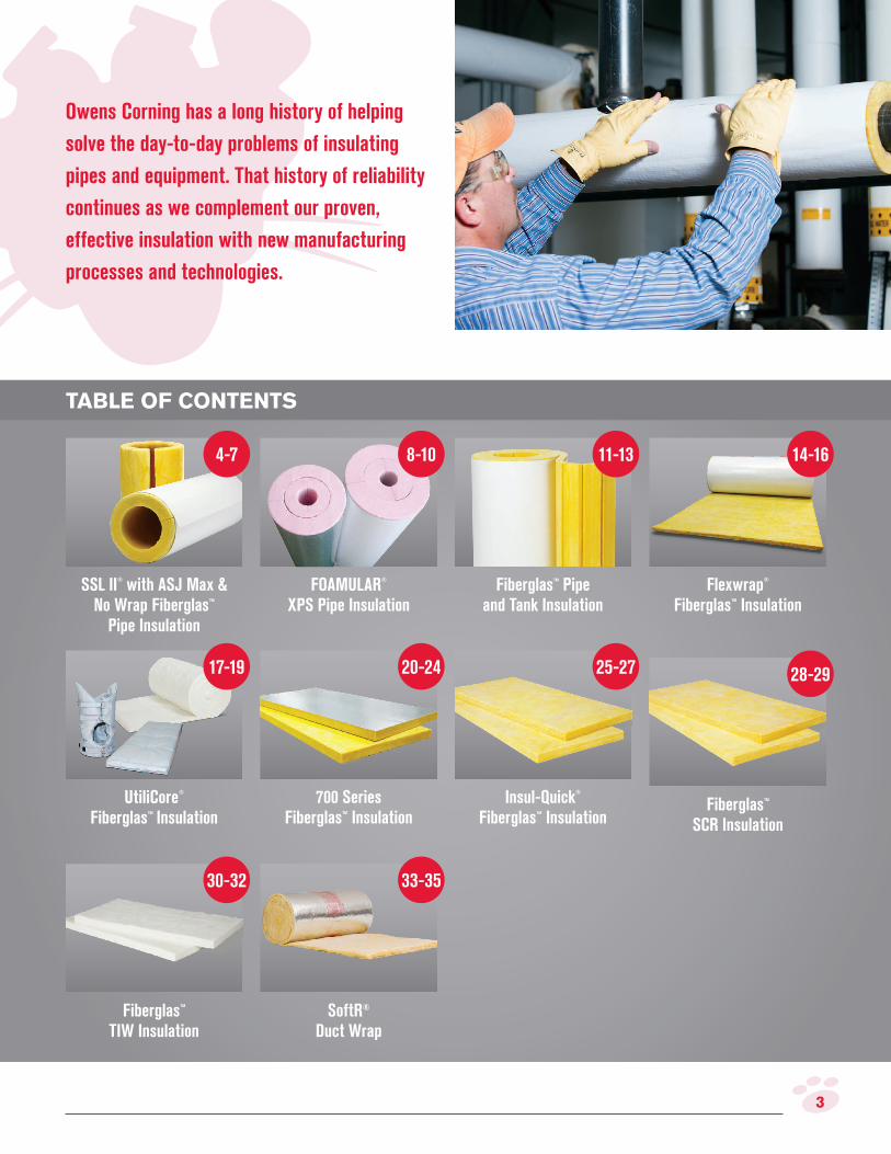
TABLE OF CONTENTS
Owens Corning has a long history of helping
solve the day-to-day problems of insulating
pipes and equipment. That history of reliability
continues as we complement our proven,
effective insulation with new manufacturing
processes and technologies.
FOAMULAR®
XPS Pipe Insulation
SSL II®
with ASJ Max & No Wrap Fiberglas™
Pipe Insulation
8-10
Fiberglas™ Pipe and Tank Insulation
4-7 11-13
700 Series Fiberglas™ Insulation
UtiliCore®
Fiberglas™ Insulation
Flexwrap®
Fiberglas™ Insulation
20-24
Insul-Quick®
Fiberglas™ Insulation
25-27
SoftR® Duct Wrap
Fiberglas™ TIW Insulation
Fiberglas™ SCR Insulation
28-29
30-32 33-35
17-19
14-16

4 SSL II®
with ASJ Max and No Wrap Fiberglas™ Pipe Insulation
Fiberglas™ Pipe Insulation is a cost-effective
solution for hot, cold, concealed and exposed
piping in commercial and industrial buildings.
DESCRIPTION
SSL II® with ASJ Max and No Wrap Pipe Insulation products are one-piece, 36" (914mm) long hinged sections of Fiberglas™ Pipe Insulation that are opened, placed over the pipe and secured in place. They are molded from heavy-density, resin-bonded, inorganic glass ibers.
APPLICATION/USE
Use to insulate pipes with operating temperatures between 0°F (-18°C) and 1,000°F (538°C) (with heat-up schedule).
• Commercial buildings
• Industrial facilities
SSL II® with ASJ Max & No Wrap Fiberglas™ Pipe Insulation
FEATURES & BENEFITS
SSL II® positive closure system
• Developed speciically to work with the ASJ Max jacket to provide a tight, reliable seal without glue or staples
• Finger Lift Edge (FLE) allows for easy removal of the release liner
• Matching butt strips
ASJ Max jacket
• Durable, cleanable ASJ Max jacket
• Resists/sheds water when exposed to intermittent, short-duration precipitation during construction
• Less wicking and curling than standard ASJ
• Accepts paint and mastic as well as standard ASJ
• Higher puncture resistance than standard ASJ
• Has a inished appearance that is compatible with standard ASJ
Most sizes 3" and smaller fit over press
fittings without filleting
Maximum operating
temperature 1,000°F
ASJ Max polymer film exterior surface
Doesn’t support mold or mildew
growth1
SSL II®
positive closure system seals
without glue or staples
• Process or power plants
• Hi-rise residential buildings
1. ASJ Max jacket does not support mold growth when tested in accordance with ASTM C1338
* SSL II® positive closure system available on most pipe sizes

5SSL II®
with ASJ Max and No Wrap Fiberglas™ Pipe Insulation
SSL II® with ASJ Max installation instructions
1. Ambient application temperatures are from 25°F (-4°C) to 110°F (43°C).
2. To open the hinged insulation section, pull the lap with the release strip from the jacket.
3. Open the hinged sections and place the insulation over the pipe, taking care not to get dirt, dust or moisture on the overlap area. While preparing to close the insulation, take care not to allow the adhesive on the jacket to contact anything until the insulation is properly lined up and closed over the pipe.
4. Pull the release strip from the jacket lap. Start by pulling the lap down at the middle until the adhesive touches the adhesive strip on the jacket. Press together. Rub irmly with nylon sealing tool or squeegee from the middle of the section towards the end until the lap is securely adhered to the jacket.
5. Apply the matching butt strip centered over the adjoining pipe sections, and rub with irm pressure to complete the positive closure.
6. If the operating temperature of the system is above 100°F (37°C), it is recommend that if the pipe insulation terminates with an exposed end, apply mastic over the exposed end, per the mastic manufacturer’s instructions.
Physical property data
Property Value Test Method
Density (size dependent) 3.5 to 5.5 pcf ASTM C302
Operating Temperature Range2 0° to 1,000°F3 (–18°C to 538°C) ASTM C411
Jacket Temperature Limitation –20°F to 150°F (–29°C to 66°C) ASTM C1136
Jacket Permeance 0.02 perm ASTM E96, Proc. A
Minimum Burst Strength 100 psi ASTM D774/D774M
Fungi Resistance Meets requirements ASTM C1338
Composite Surface Burning Characteristics4Flame Spread: 25
Smoke Developed: 50UL 723, ASTM E84 or CAN/ULC-S102
2. Limited to single-layer applications above 650°F (343°C), but not greater than 6" (152mm) thickness.
3. With heat-up schedule.
4. The surface burning characteristics of these products have been determined in accordance with UL 723, ASTM E84 or CAN/ULC-S102. These standards should be used to measure and describe the properties of materials, products or assemblies in response to heat and lame under controlled laboratory conditions and should not be used to describe or appraise the ire hazard or ire risk of materials, products or assemblies under actual ire conditions. However, results of this test may be used as elements of a ire risk assessment which takes into account all of the factors which are pertinent to an assessment of the ire hazard of a particular end use. Values are reported to the nearest 5 rating.
7. If the operating temperature of the system is below 100°F (37°C), the pipe insulation terminated exposed end shall be sealed with a vapor barrier mastic applied over the exposed end per the mastic manufacturer’s instructions.
8. Apply systems identiication labels by pressure-sensitive labels, or by stencil with spray paint.
No Wrap installation instructions
1. Open the hinged sections and place over the pipe, carefully aligned and secured by wires or bands.
2. Jacket and vapor seal as required by the application.
Additional installation instructions for both
1. Outdoor applications must be protected from weather.
2. If painting is required, use only water based latex paint.
Heat-up schedule
• Pipe insulation may be installed while the system is in operation at temperatures up to 1,000°F (538°C) at a maximum thickness of 6".
• For insulation thicknesses greater than 6" (152 mm), the temperature must be increased from 500°F (260°C) to maximum temperature at a rate not exceeding 100°F (56°C) per hour.
SPECIFICATIONS

6 SSL II®
with ASJ Max and No Wrap Fiberglas™ Pipe Insulation
No Wrap availability
Pipe Size
1/2
"
1"
1-1
/2"
2"
2-1
/2"
3"
3-1
/2"
4"
4-1
/2"
5/8 CT X
7/8 CT 1/2 X X X
1-1/8 CT 3/4 X X X X
1-3/8 CT 1 X X X
1-5/8 CT 1-1/4 X X X
1-1/2 X X X
2-1/8 CT X X
2 X X X X X
2-5/8 CT X
2-1/2 X X X
3-1/8 CT X
3 X X X X X
3-5/8 CT X
3-1/2 X X X
4-1/8 CT
4 X X X X X
4-1/2 X X X
5-1/8 CT
5 X X X
6-1/8 CT
6 X X X X X X X
7 X X X
8 X X X X X X
9 X X X X
10 X X X X X X
11 X X X
12 X X X X X
14 X X X
15
16 X X X X
17 X X
18 X X X X X X X
19
20 X X X X
21
22 X X
23
24 X X X X X
25
26 X X
27
28 X X
29
30 X X X X
31
32 X
33 MTO (Made to Order). Product availability subject to change. View product
guide for details.
No Wrap Vaccum Pack is also available in select sizes. However, the No Wrap Vacuum packaging process may cause some breakdown of the mechanical properties, such as the hinge, or cause additional dust in the package. It also may impact the outside diameter of the insulation pertaining to ASTM C585. The user assumes all responsibility for meeting project insulation requirements.
SSL II®
with ASJ Max availability
Pipe Size
1/2
"
1"
1-1
/2"
2"
2-1
/2"
3"
3-1
/2"
4"
4-1
/2"
5"
5/8 CT X X X
7/8 CT 1/2 X X X X
1-1/8 CT 3/4 X X X X
1-3/8 CT 1 X X X X
1-5/8 CT 1-1/4 X X X X
1-1/2 X X X X
2-1/8 CT X X X X
2 X X X X X
2-5/8 CT X X X X
2-1/2 X X X X X
3-1/8 CT X X X
3 X X X X X
3-5/8 CT X X X
3-1/2 X X X X X
4-1/8 CT X X X X X
4 X X X X X
4-1/2 X X X X X X
5-1/8 CT X X X
5 X X X X X X X
6-1/8 CT X X X X
6 X X X X X X X X X
7 X X X X X X X
8 X X X X X X X X X
9 X X X X X X X X
10 X X X X X X X X X
11 X X X X X X X
12 X X X X X X X X X
14 X X X X X X X X X
15 X X X X X X X
16 X X X X X X X X X
17 X X X X X X
18 X X X X X X X X
19 X X X X X X
20 X X X X X X X
21 X X X X X
22 X X X X X
23 X X
24 X X X X X X X
25 X X X X X
26 X X X X X
27 X X
28 X X X X X X
29 X
30 X X X X X
31 X
32 X X X X
33 X X
MTO (Made to Order). Product availability subject to change. View product guide for details.
SSL II® with ASJ Max is available in select metric sizes for use with Aquatherm® piping systems.

7
STANDARDS & CODES COMPLIANCE
• ASTM C547, Mineral Fiber Pipe Insulation, Type I to 850°F (454°C) (no heat-up schedule needed), and Type IV to 1,000°F (538°C) (with heat-up schedule)
• ASTM C585, Inner and Outer Diameters of Thermal Insulation for Nominal Sizes of Pipe and Tubing
• ASTM C1136, Flexible Low Permeance Vapor Retarders for Thermal Insulation, Type I, II, III, IV
• ASTM C1338, Fungi Resistance of Insulation Materials and Facings
• ASTM C795, Thermal Insulation for Use in Contact with Austenitic Stainless Steel1
• MIL-PRF-22344E, Insulation, Pipe, Thermal, Fibrous Glass
• Nuclear Regulatory Commission Guide 1.36, Non-Metallic Thermal Insulation1
• MIL-DTL-24244D (Ships) Insulation Material with Special Corrosion, Chloride, and Fluoride Requirements1
• US Coast Guard 164.109/70/0 Non-Combustible
• NFPA 90A, 90B
• FHC 25/50
• Does not contain the ire retardant decabrominated diphenyl ether (decaBDE)
• New York City MEA No. 344-83, 408-07-M
Thermal conductivity
Mean Temperature
°F k*
Mean Temperature
°C λ*50 0.22 10 0.032
75 0.23 25 0.034
100 0.24 50 0.037
150 0.27 100 0.043
200 0.29 125 0.047
250 0.32 150 0.051
300 0.35 175 0.056
350 0.39 200 0.062
400 0.43 225 0.068
450 0.48 250 0.075
500 0.54 275 0.082
SSL II®
with ASJ Max and No Wrap Fiberglas™ Pipe Insulation
* k = Btu•in/hr•ft2•°F; λ = W/m•°C
Apparent thermal conductivity values determined in accordance with ASTM practice C1045 with data obtained by ASTM Test Method C335. Values are nominal, subject to normal testing and manufacturing tolerances.
Understanding k-value and R-value
k-value is the rate of heat low through a homogeneous material. A simpliied equation to determine approximate R-value, is your insulation thickness divided by your k-value (at 75°F Mean Temperature). So, the lower the k-value, the greater the insulating value for a given set of conditions. Pipe and mechanical insulation usually communicates in terms of k-value. However, R-values for pipe insulation can be found on the Fiberglas™ Pipe Insulation Dimensional Data and Nesting Chart (Pub. No. 10018078) or you can visit www.owenscorning.com and use the 3E Plus® program to get more information based on your speciic project parameters.
CERTIFICATIONS & SUSTAINABILITY
• Certiied by SCS Global Services to contain a minimum of 53% recycled glass content, 31% pre-consumer and 22% post-consumer.
• Jacketed pipe insulation is certiied to meet indoor air quality standards under the GREENGUARD Certiication Program and the GREENGUARD Gold Certiication.
• This product’s Environmental Product Declaration (EPD) has been certiied by UL Environment.
• Fiberglas™ Pipe Insulation has received the Cradle to Cradle Products Innovation Institute’s Bronze Level Material Health Certiicate
1. Preproduction qualiication testing complete and on ile. Chemical analysis of each production lot required for total conformance. Certiication needs to be speciied at time of order.
AVERAGE 53% RECYCLED CONTENT
31% PRE-CONSUMER
22% POST-CONSUMER

8
FOAMULAR®
XPS Pipe Insulation can be cut to fit many types of pipe installations.
FOAMULAR®
XPS Pipe Insulation
Extruded Polystyrene (XPS) fabrication billets have a unique closed-cell structure that resists water absorption and maintains R-value in low-temperature systems and conditions of high humidity and moisture.
DESCRIPTION
FOAMULAR® XPS Pipe Insulation is a raw block of insulation which can be cut to it a variety of applications. They are manufactured using Owens Corning’s patented Hydrovac® process, and factory-laminated using a specially formulated polyurethane-based adhesive.
APPLICATION/USE
Commercial pipe fabricators can cut FOAMULAR® XPS Pipe Insulation to it a variety of applications and individual pipe insulation parts.
• Ammonia/refrigeration lines
• Chilled water piping
• Refrigeration and cold storage systems
• Freezer rooms
• Pharmaceutical plants
• Transport pipelines
• Direct burial applications
• Saddle supports in iberglass pipe insulation systems
FEATURES & BENEFITS
• Highly resistant to moisture
• Low water absorption
• High insulating capabilities
• Long service life with consistent R-values
• Durable compressive strength of 25 PSI
• Manufactured in the USA
• Limited lifetime warranty** Warranted that the insulation will maintain 90% of its R-value for the lifetime of
the building and covers all ASTM C578 properties. See actual warranty for details, limitations and requirements.
FOAMULAR®
XPS Pipe Insulation
Pipe
Thin coat of Vapor Retarder Joint Sealant
PVC jacket
Pipe support saddle
Vapor Retarder
Vapor Retarder Joint Sealant “Buttered”
Pipe support hanger

9
Samples modiied as required to meet applicable test methods.
1. XPS foam core value
2. k = Btu•in./hr•ft2•°F; λ = W/m•°C. The lower the value, the greater the insulation power.
3. Values at yield or 10% delection, whichever occurs irst.
4. Water vapor permeance decreases as thickness increases.
5. Burning characteristics laboratory tests are not intended to describe the hazard presented by this material under actual ire conditions.
6. Test results are for FOAMULAR 4" thick product only. Thicker products may have different ire performance characteristics. Due to limits on the equipment used to test per ASTM E84, Owens Corning FOAMULAR XPS Pipe Insulation have not been tested.
7. Fire performance of products fabricated using FOAMULAR XPS Pipe Insulation may vary in the ield depending on facings and adhesives used in the fabrication process. Fabricators should be consulted if composite ire performance is required.
Physical property data
Property Value Test Method
Density 1.55 lb./ft3 (25 kg/m3) ASTM D1622
Maximum Thermal Conductivity1,2
180 days at 75°F mean temperaturek = 0.200 (λ = 0.029) ASTM C518
Maximum Compressive Strength1,3 25 psi (173 kPa) ASTM D1621
Maximum Water Absorption1 0.00–0.15% by volume ASTM E96
Maximum Water Vapor Permeance1,4 1.5 perm (86 ng/Pa × s × m2) ASTM E96
Dimensional Stability1 1.0% linear change ASTM D2126
Composite Surface Burning Characteristics1,5,6,7
Flame Spread: 5
Smoke Developed: 175ASTM E84
Maximum Service Temperature –100°F to 165°F (–73°C to 74°C)
Linear Coeficient of Thermal Expansionin/in × °F: 3.5 × 10⁻⁵
(mm/mm × °C: 6.3 × 10⁻⁵)ASTM E228
SPECIFICATIONS
Availability
FOAMULAR® XPS Pipe Insulation is available in several sizes:
• Thicknesses: - 8", 16", 20", 24"
• Width: - 24", 48"
• Length: - 37" - 120"
• Standard stock: - 24" x 48" x 74"
FOAMULAR®
XPS Pipe Insulation
Thermal conductivity
Mean Temperature
°F k*
Mean Temperature
°C λ*100 .214 37.7 .031
75 .200 23.9 .029
50 .188 10.0 .027
25 .179 -5.9 .026
0 .173 -17.8 .025
-25 .169 -31.7 .025
-50 .166 -45.6 .024
-75 .164 -59.4 .024
-100 .160 -73.3 .023
* k = Btu•in/hr•ft2•°F; λ = W/m•°C
Apparent thermal conductivity data determined in accordance with ASTM Practice C1045 with data obtained by ASTM Test Method C335. Values are nominal, subject to normal testing and manufacturing tolerances.
10
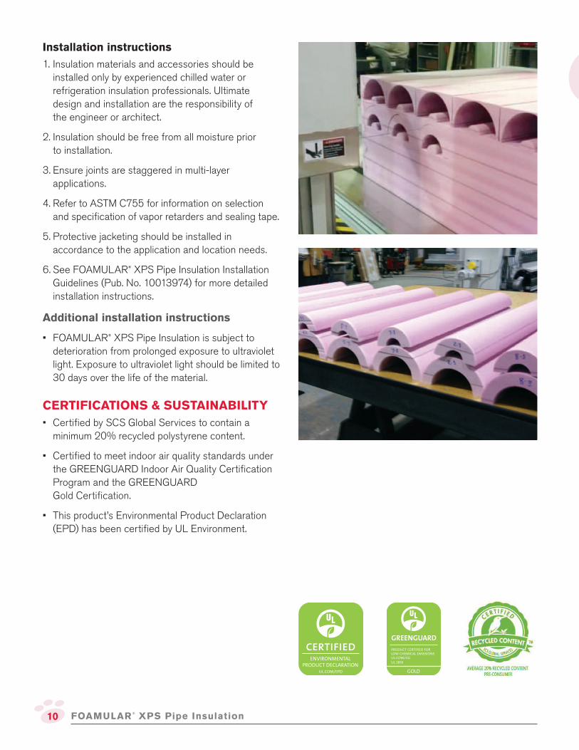
Installation instructions
1. Insulation materials and accessories should be installed only by experienced chilled water or refrigeration insulation professionals. Ultimate design and installation are the responsibility of the engineer or architect.
2. Insulation should be free from all moisture prior to installation.
3. Ensure joints are staggered in multi-layer applications.
4. Refer to ASTM C755 for information on selection and speciication of vapor retarders and sealing tape.
5. Protective jacketing should be installed in accordance to the application and location needs.
6. See FOAMULAR® XPS Pipe Insulation Installation Guidelines (Pub. No. 10013974) for more detailed installation instructions.
Additional installation instructions
• FOAMULAR® XPS Pipe Insulation is subject to deterioration from prolonged exposure to ultraviolet light. Exposure to ultraviolet light should be limited to 30 days over the life of the material.
CERTIFICATIONS & SUSTAINABILITY
• Certiied by SCS Global Services to contain a minimum 20% recycled polystyrene content.
• Certiied to meet indoor air quality standards under the GREENGUARD Indoor Air Quality Certiication Program and the GREENGUARD Gold Certiication.
• This product’s Environmental Product Declaration (EPD) has been certiied by UL Environment.
FOAMULAR®
XPS Pipe Insulation

11
Availability
Thickness Facing Recommended Pipe Size Roll Length
in. (mm) NPS in. (DN, mm) ft. (m)
1 (25) ASJ Max 10 (250) + 42 (12.8)
1-½ (38) ASJ Max 10 (250) + 27 (8.2)
2 (51) ASJ Max 10 (250) + 20 (6.1)
2 (51) FRK 10 (250) + 20 (6.1)
2-½ (64) ASJ Max 14 (350) + 26 (7.9)
2-½ (64) FRK 14 (350) + 26 (7.9)
3 (76) ASJ Max 17 (425) + 21 (6.4)
3-½ (89) ASJ Max 20 (500) + 18 (5.5)
4 (102) ASJ Max 23 (575) + 16 (4.9)
DESCRIPTION
Owens Corning’s versatile Fiberglas™ pipe and tank insulation is a semi-rigid insulation with a factory-jacketed FRK or ASJ Max encapsulated-paper jacket. It’s lexible enough to be used in many different applications while providing the rigidity and thermal performance you need for a well-insulated system.
APPLICATION/USE
Fiberglas™ Pipe and Tank insulation provides thermal protection for a variety of objects and shapes. Fits pipes and equipment of 10" NPS and larger.
• Pipes
• Tanks
• Pipe langes
Fiberglas™ Pipe and Tank Insulation provides a lexible insulation product for wrapping pipes, tanks, or irregularly shaped objects while providing excellent rigidity and abuse resistance.
Fiberglas™ Pipe & Tank Insulation
FEATURES & BENEFITS
• May be applied over existing insulation to increase thickness and conserve energy
• Vertical iber orientation with a durable, high-compressive strength makes it strong and abuse resistant
ASJ Max Jacket
• Durable, cleanable poly-encapsulate paper jacket that doesn’t support mold or mildew growth
• Resists/sheds water when exposed to intermittent, short-duration precipitation during construction
• Less wicking and curling than standard ASJ
• Accepts paint and mastic as well as standard ASJ
• Higher puncture resistance than standard ASJ
• Has a inished appearance that is compatible with standard ASJ
• Valves
• Groups of parallel pipes
• Pipes with heat tracing lines
SPECIFICATIONS
Fiberglas ™ Pipe and Tank Insulation
MTO (Made to Order). Product availability subject to change. View product guide for details. All rolls are 36" wide.

12
Thermal conductivity
Mean Temperature
°F k*
Mean Temperature
°C λ*50 0.26 10 0.037
75 0.27 25 0.040
100 0.29 50 0.045
150 0.33 75 0.050
200 0.38 100 0.056
250 0.43 125 0.063
300 0.49 150 0.070
350 0.55 175 0.078
Conductiv
ity
Btu•in
/hr•
ft.2•ºF
50 100 150 20075 250 300 350
Mean Temperature, ºF
0.2
0.3
0.4
0.5
0.6
* k = Btu•in/hr•ft2•°F; λ = W/m•°C
Apparent thermal conductivity data determined in accordance with ASTM Practice C1045 with data obtained by ASTM Test Method C335. Values are nominal, subject to normal testing and manufacturing tolerances.
Installation instructions
1. Measure the length of insulation required according to the fabrication guide located on the carton.
2. Cut completely through the insulation and jacket. Use a lap tool to illet a stapling lange on one end of the insulation.
3. Each section of insulation may be secured around the pipe using either outward-clenching staples and mastic or outward-clenching staples and pressure-sensitive, vapor-retarder tape.
4. Adjacent sections must be tightly butted together and then sealed with vapor-retarder tape.
Additional installation instructions
• Special care must be taken to vapor-seal systems operating below ambient temperatures.
• If indoor applications will be painted, use only a water-based latex paint.
• Outdoor applications require protection from weather.
1. The standard used to determine surface burning characteristics measures and describes the properties of materials, products or assemblies in response to heat and lame under controlled laboratory conditions and should not be used to describe or appraise the ire hazard or ire risk of materials, products or assemblies under actual ire conditions. However, results of this test may be used as elements of a ire risk assessment, which takes into account all of the factors that are pertinent to an assessment of the ire hazard of a particular end use. Values are reported to the nearest 5 rating.
Physical property data
Property Value Test Method
Pipe/equipment Operating Temperature
(single-layer application)0°F to 650°F (–18°C to 343°C) ASTM C411
Insulation Jacket Temperature Limitation –20°F to 150°F (–29°C to 66°C) ASTM C1136
Jacket Permeance 0.02 perm ASTM E96, Proc. A
Minimum Burst Strength 100 psi ASTM D774/D774M
Compressive Strength at 10% Deformation 125 lb./ft2 (5985 Pa) min. ASTM C165
Surface Burning Characteristics1Flame Spread: 25
Smoke Developed: 50ASTM E84
Fiberglas ™ Pipe and Tank Insulation

13
STANDARDS & CODES COMPLIANCE
• ASTM C1393, Standard Speciication for Perpendicularly Oriented Mineral Fiber Roll and Sheet Thermal Insulation for Pipes and Tanks, Types I, II, IIIA, IIIB and Category 2
• ASTM C795, Thermal Insulation for Use in Contact with Austenitic Stainless Steel2
• ASTM C1136, Flexible Low Permeance Vapor Retarders for Thermal Insulation, Types I, II, III, IV
• Mil. Spec. MIL-1-24244C, Insulation Materials, Special Requirements, Type XVlh2
• Nuclear Regulatory Commission Guide 1.36, Non-Metallic Thermal Insulation2
• Does not contain the ire retardant decabrominated diphenyl ether (decaBDE)
Thermal performance
Insulation
NPS x Thk. In. (DN x Thk. mm) Heat Loss Btu/hr x ft (W/m) Surface Temperature °F (°C)
300°F (149°C) Pipe Operating Temperature
12 × 1 (300 × 25) 251 (241) 121 (49)
18 × 1 (450 × 25) 345 (332) 122 (50)
24 × 1 (600 × 25) 453 (436) 123 (51)
30 × 1 (750 × 25) 561 (539) 123 (51)
450°F (232°C) Pipe Operating Temperature
12 × 2 (300 × 51) 292 (281) 122 (50)
18 × 2 (400 × 51) 414 (398) 126 (52)
24 × 2 (600 × 51) 539 (518) 127 (53)
30 × 2 (750 × 51) 663 (637) 127 (53)
600°F (316°C) Pipe Operating Temperature
12 × 3 (300 × 76) 370 (356) 127 (53)
18 × 3-½ (450 × 89) 449 (432) 124 (51)
24 × 3-½ (600 × 89) 576 (554) 125 (52)
30 × 3-½ (750 × 89) 702 (675) 126 (52)
Data determined in accordance with ASTM C680. Design conditions: horizontal piping, 80°F (27°C) average ambient temperature, 0 mph wind speed, ASJ Max jacket.
2. Preproduction qualiication testing complete and on ile. Chemical analysis of each production lot required for total conformance.
CERTIFICATIONS & SUSTAINABILITY
• Certiied by SCS Global Services to contain a minimum of 53% recycled glass content, 31% pre-consumer and 22% post-consumer.
AVERAGE 53% RECYCLED CONTENT
31% PRE-CONSUMER
22% POST-CONSUMER
Fiberglas ™ Pipe and Tank Insulation

14
DESCRIPTION
Flexwrap® Fiberglas™ insulation is a lexible pipe and tank wrap made from Fiberglas™ blanket bonded together with a thermosetting resin and backed with an ASJ, FRK, or PSK facing. It is a cost-effective alternative to larger-sized, preformed pipe insulation.
APPLICATION/USE
It provides a continuous blanket for round or irregularly shaped surfaces in indoor settings.
• Pipes
• Tanks
• Pipe langes
• Valves
• Groups of parallel pipes
FEATURES & BENEFITS
Flexwrap® Fiberglas™ Insulation provides lexibility for insulating pipes, tanks or irregularly shaped objects and features a low thermal conductivity.
Flexwrap®
Fiberglas™ Insulation
• Low thermal conductivity compared with segmented products, which means less thickness is required
• It its pipes and equipment of 10" NPS or larger, reducing the need to stock insulation to it pipes in multiple diameters
• Delivers good compressive strength while providing lexibility during installation
• May be applied over existing insulation to increase thickness and conserve energy
Flexwrap® Fiberglas™ Insulation is an economic and versatile choice for insulating pipes, tanks and irregularly shaped surfaces.
Flexwrap ® Fiberglas™ Insulation

15
Physical property data
Property Value Test Method
Maximum Use Temperature 850°F (454°C) ASTM C411
Density 2.5 pcf (40 kg/m3) ASTM C303
Compressive Resistance 25 psf (1200 Pa) ASTM C165
Corrosiveness Meets requirements ASTM C665
Fungi Resistance Meets requirements ASTM C1338
Facing Temperature Limit 150°F (66°C) ASTM C1136
Water Vapor Permeance (Facing) 0.02 perm ASTM E96
Surface Burning Characteristics1Flame Spread: 25
Smoke Developed: 50ASTM E84
1. The standard used to determine surface burning characteristics measures and describes the properties of materials, products or assemblies in response to heat and lame under controlled laboratory conditions and should not be used to describe or appraise the ire hazard or ire risk of materials, products or assemblies under actual ire conditions. However, results of this test may be used as elements of a ire risk assessment, which takes into account all of the factors that are pertinent to an assessment of the ire hazard of a particular end use. Values are reported to the nearest 5 rating.
MTO (Made to Order). Product availability subject to change. View product guide for details.
All rolls are 48" (1,219 mm) wide.
Installation instructions
1. When determining length requirements, remember to add twice the thickness of Flexwrap® insulation to the diameter when calculating the circumference of the piece being insulated.
2. If a lap is desired, add 3" to 4" of length and remove the additional insulation, taking care not to cut the facing, to form the lap.
3. Flexwrap® insulation is installed around the surface to be insulated, secured and either taped or stapled with outward-clenching staples. If necessary, apply a vapor-retarder mastic.
Additional installation instructions
• Adjacent sections should be butted together and sealed with tape.
• Use of bands or impalement pins for securement purposes is permitted but should be sealed as necessary with mastic.
• When the application requires a vapor seal, all joints and facing penetrations must be sealed with appropriate pressure-sensitive tape or vapor-retarder mastic.
SPECIFICATIONS
Flexwrap ® Fiberglas™ Insulation
Availability
Thickness Facing Length
Minimum Wrap
Diameter (NPS)
in. (mm) ft. (m) in. (mm)
1.5 (38) FRK 30 (9.14) 8 (203)
1.5 (38) ASJ 30 (9.14) 8 (203)
1.5 (38) PSK 30 (9.14) 8 (203)
2 (51) FRK 26 (7.92) 10 (254)
2 (51) ASJ 26 (7.92) 10 (254)
2.5 (64) FRK 20 (6.1) 12 (305)
2.5 (64) ASJ 20 (6.1) 12 (305)
2.5 (64) PSK 20 (6.1) 12 (305)
3 (76) FRK 18 (5.48) 16 (406)
3 (76) ASJ 18 (5.48) 16 (406)
16
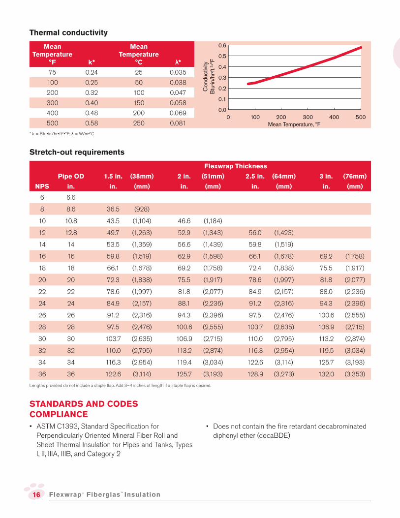
Thermal conductivity
Mean Temperature
°F k*
Mean Temperature
°C λ*75 0.24 25 0.035
100 0.25 50 0.038
200 0.32 100 0.047
300 0.40 150 0.058
400 0.48 200 0.069
500 0.58 250 0.0810 200100 300 400 500
Mean Temperature, ºF
0.0
0.1
0.2
0.3
0.4
0.5
0.6
Conductiv
ity
Btu•in
/hr•
ft.2•ºF
Stretch-out requirements
Flexwrap Thickness
Pipe OD 1.5 in. (38mm) 2 in. (51mm) 2.5 in. (64mm) 3 in. (76mm)
NPS in. in. (mm) in. (mm) in. (mm) in. (mm)
6 6.6
8 8.6 36.5 (928)
10 10.8 43.5 (1,104) 46.6 (1,184)
12 12.8 49.7 (1,263) 52.9 (1,343) 56.0 (1,423)
14 14 53.5 (1,359) 56.6 (1,439) 59.8 (1,519)
16 16 59.8 (1,519) 62.9 (1,598) 66.1 (1,678) 69.2 (1,758)
18 18 66.1 (1,678) 69.2 (1,758) 72.4 (1,838) 75.5 (1,917)
20 20 72.3 (1,838) 75.5 (1,917) 78.6 (1,997) 81.8 (2,077)
22 22 78.6 (1,997) 81.8 (2,077) 84.9 (2,157) 88.0 (2,236)
24 24 84.9 (2,157) 88.1 (2,236) 91.2 (2,316) 94.3 (2,396)
26 26 91.2 (2,316) 94.3 (2,396) 97.5 (2,476) 100.6 (2,555)
28 28 97.5 (2,476) 100.6 (2,555) 103.7 (2,635) 106.9 (2,715)
30 30 103.7 (2,635) 106.9 (2,715) 110.0 (2,795) 113.2 (2,874)
32 32 110.0 (2,795) 113.2 (2,874) 116.3 (2,954) 119.5 (3,034)
34 34 116.3 (2,954) 119.4 (3,034) 122.6 (3,114) 125.7 (3,193)
36 36 122.6 (3,114) 125.7 (3,193) 128.9 (3,273) 132.0 (3,353)
Lengths provided do not include a staple lap. Add 3–4 inches of length if a staple lap is desired.
STANDARDS AND CODES COMPLIANCE
• ASTM C1393, Standard Speciication for Perpendicularly Oriented Mineral Fiber Roll and Sheet Thermal Insulation for Pipes and Tanks, Types I, II, IIIA, IIIB, and Category 2
* k = Btu•in/hr•ft2•°F; λ = W/m•°C
• Does not contain the ire retardant decabrominated diphenyl ether (decaBDE)
Flexwrap ® Fiberglas™ Insulation
17
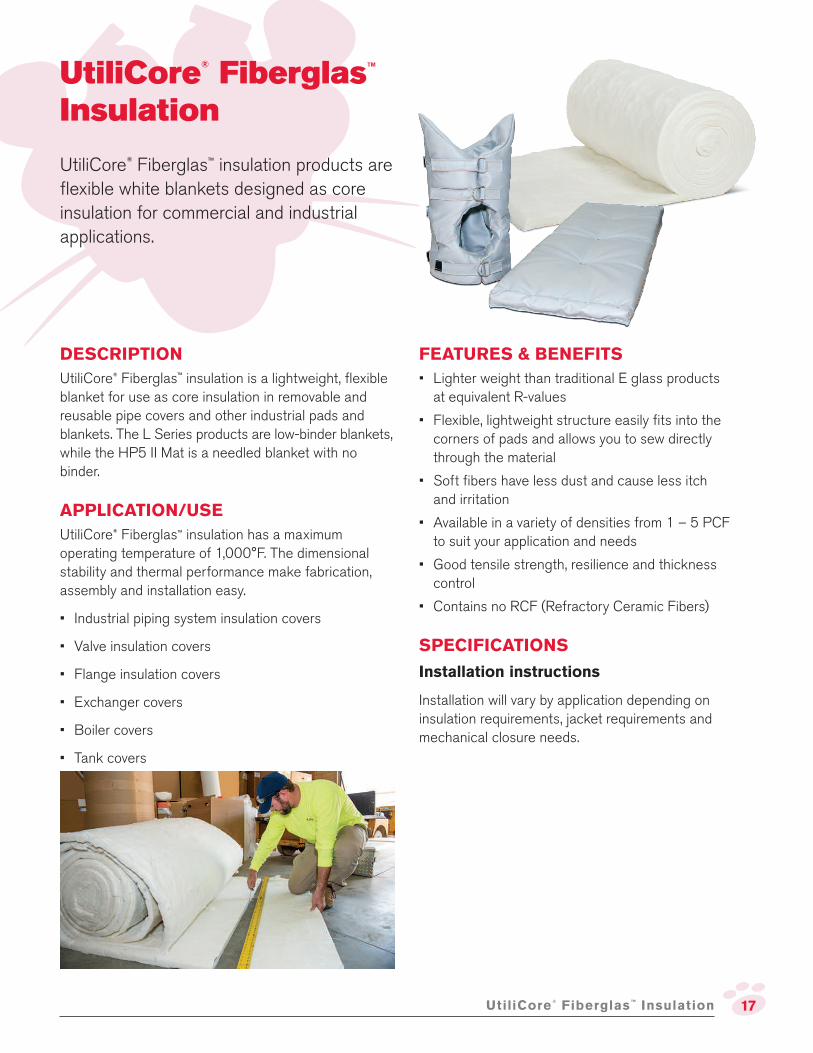
DESCRIPTION
UtiliCore® Fiberglas™ insulation is a lightweight, lexible blanket for use as core insulation in removable and reusable pipe covers and other industrial pads and blankets. The L Series products are low-binder blankets, while the HP5 II Mat is a needled blanket with no binder.
APPLICATION/USE
UtiliCore® Fiberglas™ insulation has a maximum operating temperature of 1,000°F. The dimensional stability and thermal performance make fabrication, assembly and installation easy.
• Industrial piping system insulation covers
• Valve insulation covers
• Flange insulation covers
• Exchanger covers
• Boiler covers
• Tank covers
UtiliCore® Fiberglas™ insulation products are lexible white blankets designed as core insulation for commercial and industrial applications.
UtiliCore®
Fiberglas™ Insulation
FEATURES & BENEFITS
• Lighter weight than traditional E glass products at equivalent R-values
• Flexible, lightweight structure easily its into the corners of pads and allows you to sew directly through the material
• Soft ibers have less dust and cause less itch and irritation
• Available in a variety of densities from 1 – 5 PCF to suit your application and needs
• Good tensile strength, resilience and thickness control
• Contains no RCF (Refractory Ceramic Fibers)
SPECIFICATIONS
Installation instructions
Installation will vary by application depending on insulation requirements, jacket requirements and mechanical closure needs.
UtiliCore®
Fiberglas™ Insulation

18
Physical property data
Property Value Test Method
Operating Temperature Range up to 1,000°F (538°C) ASTM C411
Corrosion Resistance Meets requirements ASTM C665
Fungi Resistance Meets requirements ASTM C1338
Odor No objectionable odor ASTM C1304
Moisture Sorption <3% by weight ASTM C1104
Composite Surface Burning Characteristics1Flame Spread: <25
Smoke Developed: <50ASTM E84, UL 723
and CAN/ULC-S102
UtiliCore®
Fiberglas™ Insulation
1. The standards used to determine surface burning characteristics measure and describe the properties of materials, products or assemblies in response to heat and lame under controlled laboratory conditions and should not be used to describe or appraise the ire hazard or ire risk of materials, products or assemblies under actual ire conditions. However, results of these tests may be used as elements of a ire risk assessment, which takes into account all of the factors that are pertinent to an assessment of the ire hazard of a particular end use. Values are reported to the nearest 5 rating.
Thermal conductivity (Core insulation only)
UtiliCore Insulation
L1 L1.3 L1.8 L2.5 L3.7 HP5 II Mat
Thickness2 (in.) 1.0 1.0 1.0 1.0 1.0 1.0
Density (pcf) 1.0 1.3 1.8 2.5 3.7 5.0
Nominal k3
75°F 0.26 0.24 0.23 0.22 0.21 0.21
300°F 0.51 0.46 0.39 0.35 0.31 0.30
500°F 0.85 0.75 0.62 0.52 0.44 0.42
Nominal λ4
23°C 0.037 0.035 0.033 0.032 0.031 0.031
149°C 0.074 0.066 0.056 0.050 0.045 0.044
260°C 0.123 0.108 0.089 0.075 0.063 0.060
2. Thickness value is nominal. Product control is on thermal conductivity.
3. k = Btu•in./hr•ft.2•°F (R-value = thickness/K)
4. λ = W/mK
Availability
ProductSingle Roll/ Double Roll
Thickness Width Length
L1 Single Roll 1” 60” 87’
L1 Double Roll 1” 60” 87’
L1.3 Single Roll 1” 60” 87’
L1.3 Double Roll 1” 60” 87’
L1.8 Single Roll 1” 60” 54’
L1.8 Double Roll 1” 60” 54’
L2.5 Single Roll 1” 60” 43’
L2.5 Double Roll 1” 60” 43’
L2.5 Single Roll 1.5” 60” 58’
MTO (Made to Order). Product availability subject to change. View product guide for details.
ProductSingle Roll/ Double Roll
Thickness Width Length
L2.5 Single Roll 2” 24” 28’
L2.5 Single Roll 2” 60” 43’
L3.7 Single Roll 1” 60” 28’
L3.7 Double Roll 1” 60” 28’
L3.7 Single Roll 2” 24” 28’
L3.7 Single Roll 2” 60” 28’
HP5 Mat Single Roll .5” 30” 100’
HP5 Mat Single Roll 1” 60” 45’
HP5 Mat Single Roll 1” 60” 50’

19UtiliCore®
Fiberglas™ Insulation
Density Variance for MIL-I-22023D
UtiliCore® insulation complies with MIL-I-22023D, with the exception of Section 1.2 Classiication; Table I Nominal Density; Type I and Type II, for Class 4 and Class 6, which are slightly below the -10% allowance, but complies to all properties required for these classes. The table below aligns the UtiliCore® insulation product for Type I and Type II Classes.
Density Required pcf (lb/ft3) UtiliCore Product Product Product Density (lb/ft3)
Class 3 1.0 L1 1.0
Class 4 1.5 L1.3 1.3
Class 5 2.0 L1.8 1.8
Class 6 3.0 L2.5 2.5
Sound absorption coeficient
Octave Band Center Frequencies, Hz
ProductThickness
(in.) 125 250 500 1000 2000 4000 NRC SAA
L1 1.0 0.09 0.31 0.65 0.85 0.90 0.90 0.70 0.68
L1.3 1.0 0.17 0.45 0.84 0.94 0.96 0.93 0.80 0.80
L1.8 1.0 0.13 0.39 0.77 0.94 1.01 0.99 0.80 0.78
L2.5 1.0 0.08 0.34 0.81 0.98 1.03 1.03 0.80 0.79
L3.7 1.0 0.10 0.57 1.09 1.17 1.12 1.17 1.00 0.99
HP5 Mat 1.0 0.13 0.43 0.84 1.05 1.02 0.94 0.85 0.83
Nominal samples were measured in accordance with ASTM C423 with Type A mounting. These measured absorption coeficients were adjusted to values representative of the product with mean speciication properties. While these values are an accurate representation of our product, they are for design approximation only. Production, testing and application variabilities will alter results. Speciic designs should be evaluated in end-use conigurations.
STANDARDS & CODES COMPLIANCE
• ASTM C553, Mineral Fiber Blanket Thermal Insulation, Type V - All UtiliCore
• ASTM C1086, Glass Fiber Mechanically Bonded Felt Thermal Insulation (HP5 Mat)
• ASTM C1139 Fibrous Glass Thermal Insulation and Sound Absorbing Blanket and Board for Military Applications
• MIL-I-16411E, Insulation Felt, Thermal, Glass Fiber
• MIL-I-22023D, Insulation Felt, Thermal and Sound Absorbing Felt, Fibrous Glass, Flexible
• ASTM C795, Thermal Insulation for Use in Contact with Austenitic Stainless Steel5
• Nuclear Regulatory Commission Guide 1.36, Non-Metallic Thermal Insulation5
• MIL-I-24244D (Ships) Insulation Material with Special Corrosion, Chloride, and Fluoride Requirements5
• U.S. Coast Guard Approval No. 164.109, Noncombustible Materials
CERTIFICATIONS & SUSTAINABILITY6
• Certiied by SCS Global Services to contain a minimum of 53% recycled glass content, 31% pre-consumer and 22% post-consumer.
• Certiied to meet indoor air quality standards under the GREENGUARD Indoor Air Quality Certiication Program and the GREENGUARD Gold Certiication.
5. Preproduction qualiication testing complete and on ile. Chemical analysis of each production lot required for total conformance.
6. Results representative of core insulation only.
• ASTM E136, Behavior of Materials in a Vertical Tube Furnace at 750°C (Noncombustible rating)
• Does not contain the ire retardant decabrominated diphenyl ether (decaBDE)
UtiliCore offers no Class 2 product.
AVERAGE 53% RECYCLED CONTENT
31% PRE-CONSUMER
22% POST-CONSUMER

20
DESCRIPTION
700 Series Fiberglas™ Insulation is made of inorganic glass ibers with a thermosetting resin binder and formed into lexible, semi-rigid or rigid rectangular boards in a variety of densities, thicknesses and facing options.
APPLICATION/USE
The range of options available for 700 Series Fiberglas™ Insulation, make it incredibly versatile and a great choice for a wide range of acoustic and thermal insulating needs.
Type 703
• Semi-rigid boards for use on mechanical equipment and HVAC ductwork
Type 705
• High strength, rigid board for use on chillers, other mechanical equipment and HVAC ductwork where high abuse resistance and good inished appearance are important
Types 706 & 707
• Smooth surface, high density, rigid boards used for acoustical wall panels and specialized ceiling applications
700 Series Fiberglas™ Insulation
FEATURES & BENEFITS
• Lightweight and resilient
• Easy to handle, fabricate and install
• Wide variety of options allows you to match your job requirements
• Types 703 and 705 are available with a factory-applied FRK or ASJ Max vapor retarder facing
ASJ Max Facing
• Durable, cleanable, poly-encapsulated paper facing that doesn’t support mold or mildew growth
• Resists/sheds water when exposed to intermittent, short-duration precipitation during construction
• Accepts paint and mastic as well as standard ASJ.
• Higher puncture resistance than standard ASJ
• Has a inished appearance that is compatible with standard ASJ
This versatile line of Fiberglas™ insulation
is great for acoustic and thermal insulation.
It helps reduce sound transmission, heat
transfer and helps save energy which can
lead to lower operating costs.*
700 Series Fiberglas™
Insulation
*Savings vary.
21
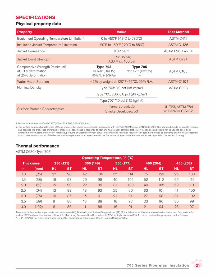
Physical property data
Property Value Test Method
Equipment Operating Temperature Limitation1 0 to 450˚F (-18˚C to 232˚C) ASTM C411
Insulation Jacket Temperature Limitation -20˚F to 150˚F (-29˚C to 66˚C) ASTM C1136
Jacket Permeance 0.02 perm ASTM E96, Proc. A
Jacket Burst StrengthFRK: 35 psi;
ASJ Max: 100 psiASTM D774
Compressive Strength (minimum) at 10% deformation at 25% deformation
Type 70325 lb/ft2 (1197 Pa)
90 lb/ft2 (4309 Pa)
Type 705200 lb/ft2 (9576 Pa)
—
ASTM C165
Water Vapor Sorption <2% by weight at 120°F (49°C), 95% R.H. ASTM C1104
Nominal Density Type 703: 3.0 pcf (48 kg/m3) ASTM C303
Type 705, 706: 6.0 pcf (96 kg/m3)
Type 707: 7.0 pcf (112 kg/m3)
Surface Burning Characteristics2Flame Spread: 25
Smoke Developed: 50UL 723, ASTM E84 or CAN/ULC-S102
1. Maximum thickness at 450˚F (232˚C): Type 703, 705, 706: 4" (102mm).
2. The surface burning characteristics of these products have been determined in accordance with UL 723, ASTM E84 or CAN/ULC-S102. This standard should be used to measure and describe the properties of materials, products or assemblies in response to heat and lame under controlled laboratory conditions and should not be used to describe or appraise the ire hazard or ire risk of materials, products or assemblies under actual ire conditions. However, results of this test may be used as elements of a ire risk assessment which takes into account all of the factors which are pertinent to an assessment of the ire hazard of a particular end use. Values are reported to the nearest 5 rating.
SPECIFICATIONS
Thermal performance
ASTM C680 (Type 703)
Operating Temperature, ˚F (˚C)
Thickness 250 (121) 300 (149) 350 (177) 400 (204) 450 (232)
in. (mm) HL ST HL ST HL ST HL ST HL ST
1.0 (25) 27 98 42 106 57 114 75 123 95 133
1.5 (38) 19 93 29 99 40 105 52 112 66 119
2.0 (5l) 15 90 22 95 31 100 40 105 50 111
2.5 (64) 12 88 18 92 25 96 32 101 41 106
3.0 (76) 10 87 15 91 21 94 27 98 34 102
3.5 (89) 9 86 13 89 18 92 23 96 30 99
4.0 (102) 8 86 11 88 16 91 21 94 26 97
The above table provides approximate heat loss values (HL), Btu/hr•ft2, and Surface Temperatures (ST), °F, for lat surfaces. Values are based on horizontal heat low, vertical lat surface, 80°F ambient temperature, still air, ASJ Max facing. To convert heat loss values to W/m2, multiply values by 3.15. To convert surface temperatures, use the formula: °C = (°F-32)/1.8. For similar information using other assumptions, contact your Owens Corning Representative.
700 Series Fiberglas™
Insulation

22
Availability
Type Facing Thickness Size Pieces/Pack
703 UF 1” 24”x48” 24
703 UF 1” 24”x48” 72
703 UF 1” 48”x96” 12
703 UF 1” 48”x96” 40
703 UF 1” 48”x96” 42
703 UF 1” 48”x96” 48
703 UF 1” 48”x120” 44
703 UF 1” 49”x72” 44
703 UF 1.5” 24”x48” 16
703 UF 1.5” 24”x48” 48
703 UF 1.5” 48”x60” 12
703 UF 1.5” 48”x96” 8
703 UF 2” 24”x48” 12
703 UF 2” 24”x48” 36
703 UF 2” 24”x48” 96
703 UF 2” 48”x96” 6
703 UF 2” 48”x96” 24
703 UF 2.5” 24x48” 8
703 UF 3” 24x48” 8
703 UF 3” 24x48” 60
703 UF 3” 36x49” 28
703 UF 3” 39x48” 7
703 UF 3” 48x96” 4
703 UF 4” 24x48” 6
703 UF 4” 24x48” 48
703 UF 4” 48x96” 12
703 UF 4” 37x48” 5
703 FRK (Foil Faced) 1” 24x48” 12
703 FRK 1” 24x48” 72
703 FRK 1” 48x96” 4
703 FRK 1.5” 24x48” 8
703 FRK 1.5” 24x48” 48
703 FRK 1.5” 48x96” 4
703 FRK 2” 24x48” 6
703 FRK 2” 24x48” 6
703 FRK 2” 24x48” 36
703 FRK 2” 48x96” 2
703 FRK 2.5” 24x48” 5
703 FRK 3” 24x48” 4
703 FRK 3.5” 24x48” 3
703 FRK 4” 24x48” 3
703 ASJ Max 1” 24x48” 12
703 ASJ Max 1.5” 24x48” 8
703 ASJ Max 2” 24x48” 6
703 ASJ Max 2” 48x96” 2
703 ASJ Max 3” 24x48” 4
703 ASJ Max 4” 48x96” 2
Type Facing Thickness Size Pieces/Pack
705 UF 0.5” 48x96” 80
705 UF 0.75” 24x48” 16
705 UF 1” 24x48” 10
705 UF 1” 48x96” 42
705 UF 1.5” 24x48” 7
705 UF 2” 24x48” 5
705 UF 2” 36x48” 6
705 UF 2” 48x96” 24
705 UF 2.5” 48x96” 18
705 UF 3” 24x48” 4
705 UF 3” 48x96” 15
705 FRK 1” 24x48” 12
705 FRK 1” 24x48” 12
705 FRK 1.5” 24x48” 8
705 FRK 1.5” 24x48” 8
705 FRK 2” 24x48” 6
705 FRK 2” 48x96” 3
705 FRK 2.5” 48x96” 18
705 FRK 3” 48x96” 15
705 ASJ Max 1” 24x48” 12
705 ASJ Max 1.5” 24x48” 8
705 ASJ Max 2” 24x48” 6
705 ASJ Max 3” 48x96” 15
706
SS (Smooth Surface)
UF (Unfaced)
1” 48x96.625” 44
706 SS UF 1” 49x73” 42
706 SS UF 1” 49x97” 42
706 SS UF 1” 49x121” 42
706 SS UF 1.5” 48x96.625” 30
706 SS UF 1.5” 48x120” 30
706 SS UF 1.5” 49x97” 30
706 SS UF 1.5” 49x121” 30
706 SS UF 2” 48x96.625” 22
706 SS UF 2” 49x73” 22
706 SS UF 2” 49x97” 22
706 SS UF 2” 49x121” 22
706 SS UF 2.5” 48x96.625” 18
707 SS UF 1” 49x73” 42
707 SS UF 1” 49x97” 42
707 SS UF 1” 49x121” 42
707 SS UF 1.5” 49x97” 30
707 SS UF 1.5” 49x121” 30
707 SS UF 2” 49x73” 22
707 SS UF 2” 49x97” 22
707 SS UF 2” 49x121” 22
MTO (Made to Order). Product availability subject to change. View product guide for details.
700 Series Fiberglas™
Insulation

23
Sound absorption coeficients
ASTM C423; Mounting: Type A–Material placed against a solid backing.
Thickness Octave Band Center Frequencies, Hz
Product Type in. (mm) 125 250 500 1000 2000 4000 NRC
703, unfaced 1 (25) 0.11 0.28 0.68 0.90 0.93 0.96 0.70
2 (51) 0.17 0.86 1.14 1.07 1.02 0.98 1.00
705, unfaced and 706 smooth surface
1 (25) 0.02 0.27 0.63 0.85 0.93 0.95 0.65
2 (51) 0.16 0.71 1.02 1.01 0.99 0.99 0.95
703, FRK 1 (25) 0.18 0.75 0.58 0.72 0.62 0.35 0.65
2 (51) 0.63 0.56 0.95 0.79 0.60 0.35 0.75
705, FRK 1 (25) 0.27 0.66 0.33 0.66 0.51 0.41 0.55
2 (51) 0.60 0.50 0.63 0.82 0.45 0.34 0.60
703, ASJ Max 1 (25) 0.17 0.71 0.59 0.68 0.54 0.30 0.65
2 (51) 0.47 0.62 1.01 0.81 0.51 0.32 0.75
705, ASJ Max 1 (25) 0.20 0.64 0.33 0.56 0.54 0.33 0.50
2 (51) 0.58 0.49 0.73 0.76 0.55 0.35 0.65
Values given are for design approximations only; production and test variabilities will alter results. Speciic designs should be evaluated in end-use conigurations.
Thermal conductivity
k, Btu•in/hr•ft2•°F λ, W/m•C
Mean Temperature ˚F 703 705, 706 Mean Temperature ˚C 703 705, 706
50 0.21 0.22 10 0.030 0.032
75 0.23 0.23 25 0.033 0.034
100 0.24 0.25 50 0.036 0.037
150 0.27 0.27 75 0.040 0.041
200 0.30 0.30 100 0.045 0.045
250 0.34 0.33 125 0.050 0.049
300 0.38 0.37 150 0.055 0.053
700 Series Fiberglas™
Insulation
Up to 48”
Up to 96”
Up to 48”
Up to 96”
Ceilings: 703 and 705 Series insulationInstallation instructions
703 and 705 Series recommended impaling
pin patterns
Pins should be located 3-8" from the edges of the board.
Walls: 703 and 705 Series insulationUp to 48”
Up to 24”

24
STANDARDS & CODES COMPLIANCE
• ASTM C553, Mineral Fiber Blanket Thermal Insulation, Type III – Type 701
• ASTM C612, Mineral Fiber Block and Board Thermal Insulation, Types IA, IB – Types 703, 705, 706, 707
• ASTM C795, Thermal Insulation For Use Over Austenitic Stainless Steel1 (except 701)
• ASTM C1136, Flexible Low Permeance Vapor Retarders for Thermal Insulation, Type I: ASJ Max; Type II: FRK
• Nuclear Regulatory Commission Guide 1.36, Non-Metallic Thermal Insulation1 (except 701)
• Doesn't contain the ire retardant decabrominated diphenyl ether (decaBDE)
• CAN/CGSB-51.10 – Type I, Class I – Types 703
• NFPA 90A and 90B
• California Insulation Quality Standards CA-T052
CERTIFICATIONS & SUSTAINABILITY
• Certiied by SCS Global Services to contain a minimum of 53% recycled glass content, 31% pre-consumer and 22% post-consumer.
• This product’s Environmental Product Declaration (EPD) has been certiied by UL Environment.
• 700 Series Fiberglas™ Insulation has received the Cradle to Cradle Products Innovation Institute’s Bronze Level Material Health Certiicate
1. Preproduction qualiication testing complete and on ile. Chemical analysis of each production lot required for total conformance. Certiication needs to be speciied at time of order.
1. Boards with ASJ Max or FRK facings shall be applied with mechanical fasteners.
2. Fasteners shall not be located less than 3” (75mm) from each edge or corner and pin spacing should be no greater than 12” (300mm) on centers.
3. Pin lengths must be selected for tight it, but avoid “oil-canning”.
4. In multi-layer applications, use faced material on the outer layer only.
5. Where a vapor retarder is required, cover pins and clips, and repair any facing tears/punctures with matching vapor sealing, pressure-sensitive patches/tape.
6. All joints should be sealed with matching pressure-sensitive tape, or glass fabric and mastic. 3” (76mm) tape for lat surfaces, or edges that are shiplapped and stapled; 5” in lieu of shiplapping.
7. For all tape and patches, seal irmly with squeegee or nylon sealing tool.
8. If applying to sheet metal duct work, all sheet metal joints must be sealed prior to insulating.
9. For vertical applications, install between furring strips, hat channels and Z-shaped furring when a inish will be applied. Exposed applications can use impaling pins or adhesive.
10. Horizontal applications should be installed using impaling pins.
11. On curtain walls, mount on impaling pins or use support clips. (Follow curtain wall manufacturer’s instructions for clearance.)
12. Masonry applications can be installed between withes, on the interior face with stick pins, or adhesive.
13. For precast concrete, use impaling pins or adhesive.
14. When using adhesive or impaling pins, follow manufacturers’ recommendations for surface preparation and use.
15. Product should be kept dry during shipping, storage and installation.
700 Series Fiberglas™
Insulation
AVERAGE 53% RECYCLED CONTENT
31% PRE-CONSUMER
22% POST-CONSUMER
25Insul-Quick®
Fiberglas™
Insulation
DESCRIPTION
Lightweight, semi-rigid Fiberglas™ board insulation that is easy to handle and install. It can be used with operating temperatures up to 850°F.
APPLICATION/USE
It’s a great option where an outside facing of metal or metal mesh with a inishing cement, is required. It can also be used as insulation in a metal panel system.
• Breechings
• Ducts
• Power and process boilers
Insul-Quick®
Fiberglas™ Insulation
Insul-Quick® Fiberglas™ Insulation
provides a low thermal conductivity and
high compressive strength.
FEATURES & BENEFITS
• Resists crumbling and breaking during installation
• Large boards help reduce the number of joints and speed installation
Physical property data
Property Value Test Method
Hot Surface Performance Up to 850°F (454°C)
Maximum thickness 6" (152mm)
Up to 650°F (343°C)
Maximum thickness 8" (203mm)
ASTM C411
Compressive Strength at 10% Deformation at 20% Deformation
90 lb/ft2 (4309 Pa)
130 lb/ft2 (6225 Pa)ASTM C165
Nominal Density 3.0 pcf (48 kg/m3) ASTM C303
Water Vapor Sorption < 2.0% by weight, at 120°F (49°C), 95% R.H. ASTM C1104
Shot Content Negligible ASTM C1335
Composite Surface Burning Characteristics1Flame Spread: 25
Smoke Developed: 50
UL 723, ASTM E84
or CAN/ULC-S1021. The surface burning characteristics of these products have been determined in accordance with UL 723, ASTM E84 or CAN/ULC-S102. This standard should be used to measure
and describe the properties of materials, products or assemblies in response to heat and lame under controlled laboratory conditions and should not be used to describe or appraise the ire hazard or ire risk of materials, products or assemblies under actual ire conditions. However, results of this test may be used as elements of a ire risk assessment which takes into account all of the factors which are pertinent to an assessment of the ire hazard of a particular end use. Values are reported to the nearest 5 rating.
SPECIFICATIONS
• Precipitators
• Chimney liners

26
Thermal Performance, ASTM C680
Operating Temperature, ˚F (˚C)
Thickness 450 (232) 550 (288) 650 (343) 750 (399) 850 (454)
in. (mm) HL ST HL ST HL ST HL ST HL ST
1 (25) 106 179 154 213 213 251 285 294 372 341
2 (51) 58 141 84 162 117 187 156 214 203 245
3 (76) 40 125 58 141 80 159 107 180 140 203
4 (102) 31 116 44 129 61 144 82 160 107 179
5 (127) 25 110 36 121 50 134 66 148 86 164
6 (152) 21 106 30 116 42 126 56 139 72 153
7 (178) 18 103 26 112 36 121 48 132
8 (203) 16 101 23 108 32 117 42 127
The above table provides approximate heat loss values (HL), Btu/hr•ft2, and Surface Temperatures (ST), ˚F, for lat surfaces. Values are based on horizontal heat low, vertical lat surface, 80˚F ambient temperature, still air, weathered aluminum jacket. To convert heat loss values to W/m2, multiply values by 3.15. To convert surface temperatures, use the formula: °C=(°F-32) 1.8.
Insul-Quick®
Fiberglas™
Insulation
Thermal conductivity
Mean Temperature
°F k*
Mean Temperature
°C λ*75 0.23 25 0.033
100 0.24 50 0.037
200 0.30 100 0.045
300 0.37 150 0.054
400 0.46 200 0.066
500 0.58 250 0.081
* k = Btu•in/hr•ft2•°F; λ = W/m•°C
Apparent thermal conductivity curve determined in accordance with ASTM Practice C1045 with data obtained by ASTM Test Method C177. Values are nominal, subject to normal testing and manufacturing tolerances.
0 200100 300 400 500
Mean Temperature, ºF
0.2
0.3
0.4
0.5
0.6
Conductiv
ity
Btu•in
/hr•
ft.2•ºF
Installation instructions
1. Can be installed directly on hot lat or curved surfaces.
2. Attach using welding pins or studs.
3. Pins with speed washers or studs and nuts should be installed on 12”x18” (300mmx450mm) centers.
4. The sheet metal or metal mesh is secured to the same fasteners.
5. Joints of sheet metal should be offset from the joints of the insulation.
6. Panels can be erected lush to heated surfaces or away from them and secured to buckstays or breeching and ductwork angle iron stiffeners.
7. Double-layer construction with staggered joints is recommended for temeratures over 400º F.
8. Install to a maximum of 6” (152mm) at all temperatures up to 850°F, or 8” (203mm) at temperatures not over 650°F
27Insul-Quick®
Fiberglas™
Insulation
Availability
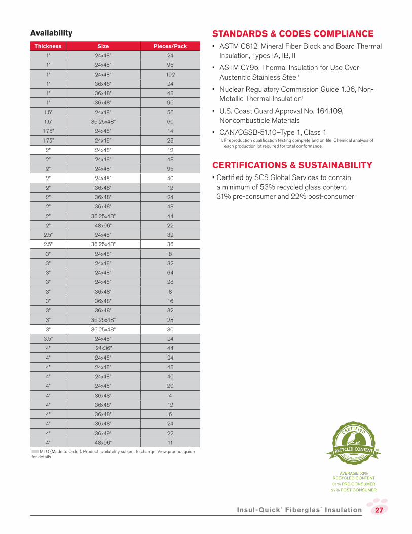
Thickness Size Pieces/Pack
1” 24x48” 24
1” 24x48” 96
1” 24x48” 192
1” 36x48” 24
1” 36x48” 48
1” 36x48” 96
1.5” 24x48” 56
1.5” 36.25x48” 60
1.75” 24x48” 14
1.75” 24x48” 28
2” 24x48” 12
2” 24x48” 48
2” 24x48” 96
2” 24x48” 40
2” 36x48” 12
2” 36x48” 24
2” 36x48” 48
2” 36.25x48” 44
2” 48x96” 22
2.5” 24x48” 32
2.5” 36.25x48” 36
3” 24x48” 8
3” 24x48” 32
3” 24x48” 64
3” 24x48” 28
3” 36x48” 8
3” 36x48” 16
3” 36x48” 32
3” 36.25x48” 28
3” 36.25x48” 30
3.5” 24x48” 24
4” 24x36” 44
4” 24x48” 24
4” 24x48” 48
4” 24x48” 40
4” 24x48” 20
4” 36x48” 4
4” 36x48” 12
4” 36x48” 6
4” 36x48” 24
4” 36x49” 22
4” 48x96” 11
MTO (Made to Order). Product availability subject to change. View product guide for details.
STANDARDS & CODES COMPLIANCE
• ASTM C612, Mineral Fiber Block and Board Thermal Insulation, Types IA, IB, II
• ASTM C795, Thermal Insulation for Use Over Austenitic Stainless Steel1
• Nuclear Regulatory Commission Guide 1.36, Non-Metallic Thermal Insulation1
• U.S. Coast Guard Approval No. 164.109, Noncombustible Materials
• CAN/CGSB-51.10–Type 1, Class 1
CERTIFICATIONS & SUSTAINABILITY
• Certiied by SCS Global Services to contain a minimum of 53% recycled glass content, 31% pre-consumer and 22% post-consumer
1. Preproduction qualiication testing complete and on ile. Chemical analysis of each production lot required for total conformance.
AVERAGE 53% RECYCLED CONTENT
31% PRE-CONSUMER
22% POST-CONSUMER
28 Fiberglas™
SCR Insulation
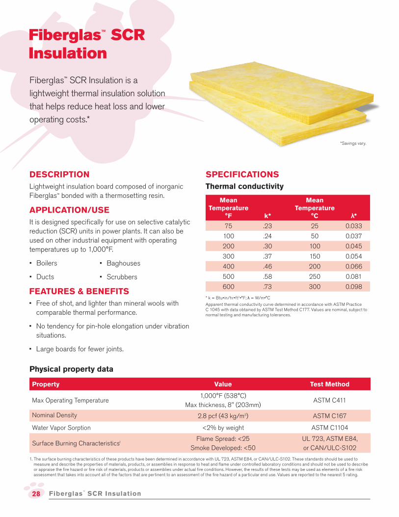
DESCRIPTION
Lightweight insulation board composed of inorganic Fiberglas™ bonded with a thermosetting resin.
APPLICATION/USE
It is designed speciically for use on selective catalytic reduction (SCR) units in power plants. It can also be used on other industrial equipment with operating temperatures up to 1,000°F.
• Boilers
• Ducts
Fiberglas™ SCR Insulation
Fiberglas™ SCR Insulation is a
lightweight thermal insulation solution
that helps reduce heat loss and lower
operating costs.*
FEATURES & BENEFITS
• Free of shot, and lighter than mineral wools with comparable thermal performance.
• No tendency for pin-hole elongation under vibration situations.
• Large boards for fewer joints.
Physical property data
Property Value Test Method
Max Operating Temperature1,000°F (538°C)
Max thickness, 8" (203mm)ASTM C411
Nominal Density 2.8 pcf (43 kg/m3) ASTM C167
Water Vapor Sorption <2% by weight ASTM C1104
Surface Burning Characteristics1Flame Spread: <25
Smoke Developed: <50
UL 723, ASTM E84,
or CAN/ULC-S102
1. The surface burning characteristics of these products have been determined in accordance with UL 723, ASTM E84, or CAN/ULC-S102. These standards should be used to measure and describe the properties of materials, products, or assemblies in response to heat and lame under controlled laboratory conditions and should not be used to describe or appraise the ire hazard or ire risk of materials, products or assemblies under actual ire conditions. However, the results of these tests may be used as elements of a ire risk assessment that takes into account all of the factors that are pertinent to an assessment of the ire hazard of a particular end use. Values are reported to the nearest 5 rating.
SPECIFICATIONS
• Baghouses
• Scrubbers
Thermal conductivity
Mean Temperature
°F k*
Mean Temperature
°C λ*75 .23 25 0.033
100 .24 50 0.037
200 .30 100 0.045
300 .37 150 0.054
400 .46 200 0.066
500 .58 250 0.081
600 .73 300 0.098
* k = Btu•in/hr•ft2•°F; λ = W/m•°C
Apparent thermal conductivity curve determined in accordance with ASTM Practice C 1045 with data obtained by ASTM Test Method C177. Values are nominal, subject to normal testing and manufacturing tolerances.
*Savings vary.

29Fiberglas™
SCR Insulation
Thermal Performance, ATSM, C680
Operating Temperature, ˚F (˚C)
Thickness 450 (232) 550 (288) 650 (343) 750 (399) 850 (454)
in. (mm) HL ST HL ST HL ST HL ST HL ST
2 (51) 58 141 84 162
3 (76) 40 125 58 141 80 159
4 (102) 31 116 44 129 61 144 82 160 107 179
5 (127) 25 110 36 121 50 134 66 148 86 164
6 (152) 21 106 30 116 42 126 56 139 72 153
7 (178) 18 103 26 112 36 121 48 132 62 145
8 (203) 16 101 23 108 32 117 42 127 55 138The above table provides approximate heat loss values (HL) Btu/hr•ft2•°F, and Surface Temperatures (ST), °F, for lat surfaces. Values are based on horizontal heat low, vertical lat surface, 80°F ambient temperature, still air, weathered aluminum jacket with emmitance of 0.2. To convert heat loss values to W/m2, multiply values by 3.15. To convert surface temperatures, use the formula: °C=(°F-32) 1.8.
Installation instructions
1. Can be installed directly on hot lat or curved surfaces.
2. Attach using welding pins or studs and hold in place with wire ties, metal lath or lagging
3 Pins with speed washers or studs and nuts should be installed on 12”x18” (300mmx450mm) centers.
4. The sheet metal lagging is secured to the same fasteners.
5. Joints of sheet metal should be offset from the joints of the insulation.
6. Panels can be erected lush to heated surfaces or away from them and secured to buckstays or breeching and ductwork angle iron stiffeners.
7. Install to a maximum of 8” up to 1,000°F
8. Double-layer constructions with staggered joints is recommended.
9. During initial heat-up to operating temperatures above 400°F the organic binders decompose and an acrid odor and some smoke may be given off. Make sure area is properly ventilated.
Availability
Thickness Size Pieces/Pack
1” 24x48” 24
1.5” 24x48” 16
1.5” 24x48” 56
1.5” 36.125x48” 14
1.5” 36.125x48.25” 14
1.5” 36.25x48.25” 14
1.5” 48x96” 32
2” 24x48” 12
2” 24x48” 48
2” 24x48.25” 10
2” 36.125x48.25” 10
2” 40.25x48” 10
2” 44.125x48” 10
2” 48x96” 24
2.5” 24x48” 8
3” 24x48” 8
3” 24x48” 32
3” 36.125x48” 7
3” 36.125x48.25” 7
3” 44.125x48” 32
4” 24x48” 6
4” 48x96” 3
MTO (Made to Order). Product availability subject to change. View product guide for details.STANDARDS & CODES COMPLIANCE
• ASTM C612 Mineral Fiber Block and Board Thermal Insulation, (Types IA, IB, II and III, Category 1)
AVERAGE 53% RECYCLED CONTENT
31% PRE-CONSUMER
22% POST-CONSUMER
CERTIFICATIONS & SUSTAINABILITY
• Certiied by SCS Global Services to contain a minimum of 53% recycled glass content, 31% pre-consumer and 22% post-consumer.

30
DESCRIPTION
Noncombustible insulation made from Inorganic Fiberglas™ bonded with a thermosetting resin. Type I-HP is manufactured in roll form, while Type II-HP comes in batt form.
APPLICATION/USE
It is available in a variety of density and thickness combinations, making this incredibly versatile and well-suited for a variety of commercial and industrial uses with operating temperatures up to 1,000°F.
• Panel systems
• Industrial ovens
• Flexible wrap for irregular surfaces
• Metal mesh blankets (Type II-HP only)
Fiberglas™ TIW Insulation
Fiberglas™ TIW Insulation is
available in a batt or roll. It offers a
high operating temperature and the
lightweight, low-density construction
makes it easy to cover large areas to
lower equipment operating costs.
FEATURES & BENEFITS
• Easy to handle and install
• No tendency for pin-hole elongation under vibration situations
• Large batts/blankets cover areas quickly with no need to drill for studs
• Type II-HP has a higher density and is better suited for applications where more compressive resistance is needed
Physical property data
PropertyType I-HP
Value
Type II-HP
ValueTest Method
Equipment Operating Temperature Range1 Up to 1,000°F (538°C) ASTM C411
Nominal Density 1.0 pcf (16 kg/m3) 2.5 pcf (40 kg/m3) ASTM C167
Shot Content Negligible ASTM C1335
Water Vapor Sorption < 2.0% by weight at 120°F (49°C), 95% R.H. ASTM C1104
Surface Burning Characteristics2Flame Spread: 25
Smoke Developed:50
UL 723, ASTM E84
or CAN/ULC-S1021. Maximum allowable thickness at 1,000°F (538°C): Type I-HP - 8.5" (216mm); Type II-HP - 6" (152mm).
2. The surface burning characteristics of these products have been determined in accordance with UL 723, ASTM E84 or CAN/ULC-S102. This standard should be used to measure and describe the properties of materials, products or assemblies in response to heat and lame under controlled laboratory conditions and should not be used to describe or appraise the ire hazard or ire risk of materials, products or assemblies under actual ire conditions. However, results of this test may be used as elements of a ire risk assessment which takes into account all of the factors which are pertinent to an assessment of the ire hazard of a particular end use. Values are reported to the nearest 5 rating.
SPECIFICATIONS
Fiberglas™
TIW Insulation
• Boilers
• Precipitators

31
Thermal performance, ASTM C680
Operating Temperature, ˚F (˚C)
Thickness 400 (204) 600 (316) 800 (427) 1,000 (538)
in. (mm) HL ST HL ST HL ST HL ST
TIW
Typ
e I-
HP
1 (25) 109 182 241 275 435 394 699 533
2 (51) 61 143 136 201 249 281 409 379
3 (76) 43 126 95 171 174 230 287 305
4 (102) 32 116 73 153 133 201 221 262
5 (127) 27 110 59 141 108 182 179 233
6 (152) 22 106 49 133 91 168 151 213
7 (178) 19 102 43 126 79 157 130 198
8 (203) 17 99 38 121 69 150 114 186
TIW
Typ
e II-
HP
1 (25) 81 160 167 225 289 306 453 404
2 (51) 45 128 92 167 159 219 251 282
3 (76) 31 115 63 145 109 183 173 229
4 (102) 23 107 48 131 84 162 132 198
5 (127) 19 109 39 123 68 148 106 180
6 (152) 16 99 33 117 57 139 89 167The above table provides approximate heat loss values (HL), Btu/hr•ft2, and Surface Temperatures (ST), ˚F, for lat surfaces. Values are based on horizontal heat low, vertical lat surface, 80˚F ambient temperature, still air, weathered aluminum jacket. To convert heat loss values to W/m2, multiply values by 3.15. To convert surface temperatures, use the formula: °C = (°F-32)/1.8.
Fiberglas™
TIW Insulation
Thermal conductivity
Mean Temperature
°F k*
Mean Temperature
°C λ*
TIW
Typ
e I-
HP
75 0.26 25 0.037
100 0.28 50 0.040
200 0.38 100 0.055
300 0.52 150 0.075
400 0.68 200 0.098
500 0.86 250 0.124
600 1.06 300 0.156
TIW
Typ
e II-
HP
75 0.22 25 0.032
100 0.23 50 0.033
200 0.28 100 0.040
300 0.35 150 0.050
400 0.43 200 0.062
500 0.53 250 0.076
600 0.64 300 0.092
Installation instructions
1. Can be installed directly on hot lat or curved surfaces.
2. Attach using welding pins or studs and inish with sheet metal or metal mesh and insulating cement, then canvassed and painted.
3. Pins with speed washers or studs and nuts should be installed on 16” (400mm) maximum spacing, not more than 4” from the edge of the insulation.
4. The sheet metal lagging is secured to the same fasteners.
5. Joints of sheet metal should be offset from the joints of the insulation.
6. Install to a maximum of 8.5” (Type I-HP) and 6” (Type II-HP) up to 1,000°F
7. Double-layer constructions with staggered joints is recommended for temperatures over 400°F

32
AvailabilityProduct Style Thickness Width Length
Type I-HP Bisected Roll 1” 24” 87’
Type I-HP Bisected Roll 1” 48” 87’
Type I-HP Bisected Roll 1.5” 36” 58’
Type I-HP Bisected Roll 1.5” 48” 58’
Type I-HP Single Roll 2” 24” 87’
Type I-HP Single Roll 2” 36” 87’
Type I-HP Single Roll 2” 48” 87’
Type I-HP Single Roll 3” 48” 44’
Type I-HP Single Roll 3” 48” 50’
Type I-HP Single Roll 4” 48” 39’
Type I-HP Single Roll 4” 48” 40’
Type I-HP Single Roll 4” 48” 44’
TYPE II-HP Bisected Batt 1” 24” 48”
TYPE II-HP Bisected Batt 1.5” 24” 48”
TYPE II-HP Single Layer Loose 1.5” 48” 46.5”
TYPE II-HP Single Layer Batt 2” 24” 48”
TYPE II-HP Single Layer Roll 2.125” 72” 26’
TYPE II-HP Single Layer Roll 2.125” 72” 52’
TYPE II-HP Single Layer Batt 2.5” 24” 48”
TYPE II-HP Single Layer Batt 3” 24” 48”
TYPE II-HP Single Layer Roll 4” 24” 48”
MTO (Made to Order). Product availability subject to change. View product guide for details.
STANDARDS & CODES COMPLIANCE
• ASTM C553, Mineral Fiber Blanket Thermal Insulation, Types I, II, V – TIW Type I-HP; all types – TIW Type II-HP when speciication Type VII is limited to 1,000°F maximum use temperature.
• ASTM C612, Mineral Fiber Block & Board Thermal Insulation, Types IA, II, III – TIW Type II-HP
• ASTM C795, Thermal Insulation for Use Over Austenitic Stainless Steel1
• ASTM C1139, Fibrous Glass Thermal Insulation and Sound Absorbing Blanket and Board for Military Applications, Type 1, Grade 2 – TIW Type I-HP; Type 2, Grade 2 – TIW Type II-HP
• Mil. Spec. MIL-I-22023D (Ships), Insulation Felt, Thermal and Sound Absorbing Felt, Fibrous Glass, Flexible, Types 1 & 2, Class 3 – TIW Type I-HP
• Nuclear Regulatory Commission Guide 1.36, Non-Metallic Thermal Insulation1
• U.S. Coast Guard Approval No. 164.109, Noncombustible Materials
• CAN/CGSB-51.11 – Type 1, Class 4 – Fiberglas™ TIW Types I-HP & II-HP Insulation
CERTIFICATIONS & SUSTAINABILITY
• Certiied by SCS Global Services to contain a minimum of 53% recycled glass content, 31% pre-consumer and 22% post-consumer.
AVERAGE 53% RECYCLED CONTENT
31% PRE-CONSUMER
22% POST-CONSUMER
1. Preproduction qualiication testing complete and on ile. Chemical analysis of each production lot testing required for total conformance.
Fiberglas™
TIW Insulation
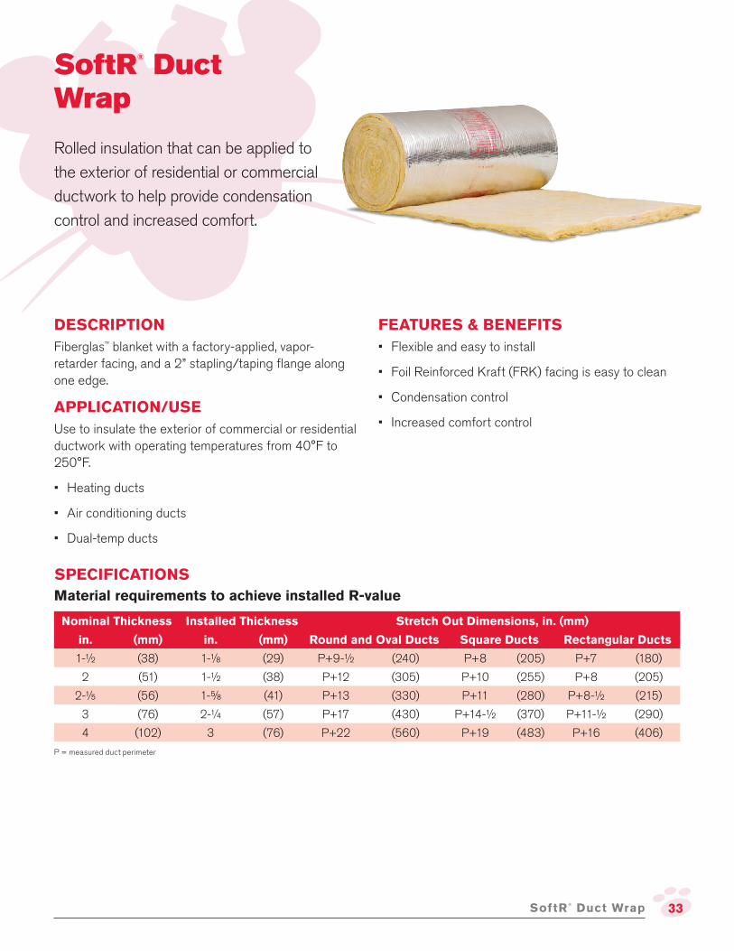
33SoftR®
Duct Wrap
DESCRIPTION
Fiberglas™ blanket with a factory-applied, vapor-retarder facing, and a 2” stapling/taping lange along one edge.
APPLICATION/USE
Use to insulate the exterior of commercial or residential ductwork with operating temperatures from 40°F to 250°F.
• Heating ducts
• Air conditioning ducts
• Dual-temp ducts
SoftR®
Duct Wrap
Rolled insulation that can be applied to
the exterior of residential or commercial
ductwork to help provide condensation
control and increased comfort.
FEATURES & BENEFITS
• Flexible and easy to install
• Foil Reinforced Kraft (FRK) facing is easy to clean
• Condensation control
• Increased comfort control
SPECIFICATIONS
Material requirements to achieve installed R-value
Nominal Thickness Installed Thickness Stretch Out Dimensions, in. (mm)
in. (mm) in. (mm) Round and Oval Ducts Square Ducts Rectangular Ducts
1-½ (38) 1-⅛ (29) P+9-½ (240) P+8 (205) P+7 (180)
2 (51) 1-½ (38) P+12 (305) P+10 (255) P+8 (205)
2-� (56) 1-⅝ (41) P+13 (330) P+11 (280) P+8-½ (215)
3 (76) 2-¼ (57) P+17 (430) P+14-½ (370) P+11-½ (290)
4 (102) 3 (76) P+22 (560) P+19 (483) P+16 (406)
P = measured duct perimeter

34
Physical property data
Property Value Test Method
Operating Temperature up to 250°F (121°C) ASTM C411
Insulation Jacket Temperature Limit up to 150°F (66°C) ASTM C1136
Jacket Puncture Resistance 25 units (0.7 joules) ASTM C1136
Water Vapor Permeance 0.02 perms ASTM E96
Water Vapor Sorption <3% by weight at 120°F (49°C), 95% R.H. ASTM C1104
Fungi Resistance Meets requirements ASTM C1338
Thermal ConductivityOut-of-Package k-Valuek Btu•in/hr•ft2•°F(λ at 24°C Mean, W/m•°C)
Installed (Compressed) k-Valuek Btu•in/hr•ft2•°F(λ at 24°C Mean, W/m•°C)
Type 750.30
(0.043)
Type 750.27
(0.039)
Type 1000.27
(0.039)
Type 1000.25
(0.036)
Type 1500.25
(0.036)
Type 1500.23
(0.033)
ASTM C518
Surface Burning Characteristics1Flame Spread: 25
Smoke Developed: 50ASTM E84
1. The surface burning characteristics of these products have been determined in accordance with ASTM E 84. This standard should be used to measure and describe the properties of materials, products or assemblies in response to heat and lame under controlled laboratory conditions and should not be used to describe or appraise the ire hazard or ire risk of materials, products or assemblies under actual ire conditions. However, results of this test may be used as elements of a ire risk assessment which takes into account all of the factors which are pertinent to an assessment of the ire hazard of a particular end use. Values are reported to the nearest 5 rating.
SoftR®
Duct Wrap
Availability & installed R-values
Standard roll width: 48” (1.2m)
Installed R (RSI) values: When installed in accordance with recommended installation procedures, SoftR® Duct Wrap will provide installed R (RSI) values as follows:
Nominal Thickness Out-of-Package
R (RSI) Value1
Installed Thickness2
Installed R (RSI) Value1,2
Roll Lengthin. mm in. mm
TYPE 75 – 0.75 pcf (12 kg/m3)
1.5 (38) 5.1 (0.90) 1-1/8 (29) 4.2 (0.74) 100’
2.0 (50) 6.8 (1.17) 1-1/2 (38) 5.6 (0.98) 75’
2.2 (56) 7.4 (1.30) 1-5/8 (42) 6.0 (1.06) 75’
3.0 (76) 10.0 (1.76) 2-1/4 (57) 8.3 (1.46) 50’
TYPE 100 – 1.00 pcf (16 kg/m3)
1.5 (38) 5.6 (0.99) 1-1/8 (29) 4.5 (0.79) 100’
2.0 (51) 7.4 (1.30) 1-1/2 (38) 6.0 (1.06) 75’
TYPE 150 – 1.50 pcf (24 kg/m3)
1.5 (38) 6.0 (1.06) 1-1/8 (29) 4.8 (0.85) 75’
2.0 (51) 8.0 (1.41) 1-1/2 (38) 6.4 (1.13) 50’
1. hr•ft2•°F/Btu (m2•°C/W) at 75°F (24°C) mean temperature.
2. Assumes 25% compression of insulation.

35
STANDARDS & CODES COMPLIANCE
• NFPA 90A and 90B
• ASTM C1290, Flexible Fibrous Glass Blanket Insulation Used to Externally Insulate HVAC Ducts, Type III
• ASTM C1136, Flexible Low Permeance Vapor Retarders for Thermal Insulation, Type II (facing only)
• ASTM C553* Mineral Fiber Thermal Insulation: Type I – Fiberglas™ Duct Wrap Type 75; Type II – SOFTR® Duct Wrap FRK Types 100 and 150. (Operating temperatures to 250°F (121°C) and thermal values to 150°F (66°C) mean.*Preferred speciication is ASTM C1290.
NOTE TO SPECIFIERS – Federal Speciication HH-I-558B (Amendment 3), Form B (covering the duct wrap), and Federal Speciication HH-B-100B (Covering the facing and CAN/CGSB-51.11), are obsolete. These are replaced by the above referenced ASTM speciications.
CERTIFICATIONS & SUSTAINABILITY
• Certiied by SCS Global Services to contain a minimum of 53% recycled glass content, 31% pre-consumer and 22% post-consumer.
• Certiied to meet indoor air quality standards under the GREENGUARD Indoor Air Quality Certiication Program, and the GREENGUARD Gold Certiication.
• SoftR® Duct Wrap has received the Cradle to Cradle Products Innovation Institute's Bronze Level Material Health Certiicate.
Nominal duct wrap thickness to prevent surface condensation
The above chart is based on indoor conditions so far as wind and other factors are concerned.
Thermal conductivity
Apparent thermal conductivity curve determined in accordance with ASTM Practice C1045 with data obtained by ASTM Test Method C177. Values are nominal, subject to normal testing and manufacturing tolerances.
SoftR®
Duct Wrap
Installation instructions
1. Ensure that ducts are clean, dry and tightly sealed at joints and seams.
2. Cut to stretch-out dimensions and remove 2" of insulation from facing.
3. Install duct wrap tightly butted with facing outside. (Make sure to not excessively compress at duct corners).
4. Adjacent sections should have the 2" tape lap overlapping
5. Seams should be stapled 6" on center with outward clinching staples.
6. Seal all seams and joints with matching pressure sensitive tape or with glass fabric and mastic.
7. On rectangular ducts 24" or wider, SoftR® Duct Wrap should be secured at the bottom of the duct with mechanical fasteners to prevent sagging of insulation.
8. Where a vapor retarder is required, cover and repair any facing tears/punctures with matching vapor sealing, pressure-sensitive patches/tape.
Product should be kept dry during shipping, storage and installation. It should not be used on the inside of ducts.
AVERAGE 53% RECYCLED CONTENT
31% PRE-CONSUMER
22% POST-CONSUMER
40 50 60 70 80 90
90
80
70
100
110 (43)
(38)
(32)
(27)
(21)
Ambient temperatureºF ºC
1½"(38mm)required
More than3" (75mm)required
Nonerequired
2"(51mm)required
3"(75mm)required
More than3" (75mm)required
2"(51mm)required
3"(75mm)required
25(-38)
50(10)
75(23.8)
100(37.7)
125(51.6)
150 (ºF)(65.5) (ºC)
0.45
0.40
0.35
0.30
0.25
0.20
k, Btu•in/hr•ft2•ºF
Type 750.30
(0.043)
Type 1000.27
(0.030)
Type 1500.25
(0.036)

Pub. No. 10020231-D. Printed in U.S.A. September 2018.THE PINK PANTHER™ & © 1964–2018 Metro-Goldwyn-Mayer Studios Inc.All Rights Reserved. The color PINK is a registered trademark of Owens Corning. © 2018 Owens Corning. All Rights Reserved.
OWENS CORNING INSULATING SYSTEMS, LLC ONE OWENS CORNING PARKWAY TOLEDO, OHIO, USA 43659
1-800-GET-PINK® www.owenscorning.com
Disclaimer of Liability
Technical information contained herein is furnished without charge or obligation and is given and accepted at recipient’s sole risk. Because conditions of use may vary and are beyond our control, Owens Corning makes no representation about, and is not responsible or liable for the accuracy or reliability of, data associated with particular uses of any product described herein.
SCS Global Services provides independent veriication of recycled content in building materials and veriies recycled content claims made by manufacturers. For more information, visit www.SCSglobalservices.com.
GREENGUARD Certiied products are certiied to GREENGUARD standards for low chemical emissions into indoor air during product usage. For more information, visit ul.com/gg.
Owens Corning delivers high-performance residential and commercial building and industrial insulation solutions through a full line of iberglass, foam and mineral wool products and systems. These products and system solutions help conserve energy, improve acoustics and ease installation and use.
Owens Corning applies the principles of building science to develop safe, sustainable, durable, eficient and affordable solutions that address thermal, air, and moisture performance for the entire building envelope.
• Owens Corning is the most recognized brand in the insulation industry thanks to our long history and proven reputation.
• Owens Corning has the building materials expertise to help you succeed. Whether leading building science initiatives or taking an active role in code and standard updates – we have the experience to help.
• Our belief in proven product performance quality and stewardship shows in our commitment to testing and doing the right thing.
• We are dedicated to the insulation market and the depth and breadth of our product portfolio shows that. You’ll ind iberglass, mineral wool, and XPS all under one roof.
• Our support extends to fast, reliable, transparent and lexible replenishment. From designing solutions that are channel/market speciic to portals, end-to-end supply chain visibility and more.
Learn more at www.owenscorning.com


![supreme court reports [2011] 6 scr](https://static.fdokumen.com/doc/165x107/63226297aa6c954bc707acc5/supreme-court-reports-2011-6-scr.jpg)