Sound Control - R-Pro Insulation Professionals
34
Sound Control ®
-
Upload
khangminh22 -
Category
Documents
-
view
0 -
download
0
Transcript of Sound Control - R-Pro Insulation Professionals

Sound Control
®


Sound Control
Table of Contents
Sound Control in Residential Construction ....................................................................................................................................................1
The Basics of Sound ......................................................................................................................................................................................................3
Construction Techniques for Sound Control ................................................................................................................................................5
A "System" Approach to sound Control ..........................................................................................................................................................7
Sound Control Terminology .................................................................................................................................................................................10
Noise Control Guide ...............................................................................................................................................................................................11More detailed discussion of:Technical Principles of SoundAcoustical Performance of Various Materials and Systems
Construction Designs for Acoustical Control
Wall System Selection Chart for Wood Stud Walls ..............................................................................................................................22
Wall System Selection Chart for Metal Stud Walls .................................................................................................................................24
Sound Control Questions
To Test Your Knowledge .......................................................................................................................................................................................27


Sound Control
1
Sound Control in
Residential Construction
Overview
Interior sound control construction practices have been an important consideration for both multi-family and commercial construction for many years. Traditionally, interior sound control for single family construction has been limited and generally reserved for high-end homes. However, things are changing, meaning new opportunities for increased insulation sales.
The growing trade-up market, fueled primarily by baby boomers, is fi nding a more demanding home buyer. Customers who have previously owned homes know what they want, and don’t want, in a new home. They are more interested in the detail and fi nishing touches that add quality, including sound control within the home. Those who are moving up from tract or production-built homes are especially aware of interior household noise.
In addition, recent lifestyle changes are moving the family and home back into the center of our lives.
Amenities, layout and well-planned spaces that can increase the quality of family life are key. Not only is there an increased focus on comfortable family living spaces, such as kitchens and family rooms, but on private spaces as well. Home buyers are looking for secluded retreats in bedrooms and baths, where individual family members can have privacy and quiet, away from other household activity.
With quality, comfort and quiet becoming top priorities for home buyers, there is an increased interest in sound control, substantiated by a recent con-sumer survey. Over 60% of the homeowners surveyed felt that reducing the noise level in a home is more important than it used to be, saying they would be interested in a new home that was designed to be quieter. Further, 35% said they would pay as much as an additional $500 to reduce that noise level in a new home.
The survey also identifi ed critical areas for sound control and privacy in a home. Respondents noted that they would be most
Agree
Completely
Agree
Somewhat
Disagree Don’t Know
50%
40%
30%
20%
10%
0%
22%
40%
23%
15%
Reducing the noise level in a home is more important than it used to be.
Agree
Completely
Agree
Somewhat
Disagree Don’t Know
50%
40%
30%
20%
10%
0%
43%
19%
4%
34%
Whenever I have looked at new homes, the salesperson almost never talked about sound control features.
Agree
Completely
Agree
Somewhat
Disagree Don’t Know
40%
35%
30%
25%
20%
15%
10%
5%
0%
26%
34%
21%19%
I would be very interested in a new home that was designed to be quieter.
Agree
Completely
Agree
Somewhat
Disagree Don’t Know
50%
40%
30%
20%
10%
0%
13%
22%
42%
23%
I would pay as much as $500 more to reduct the noise level in a new home.
Bedrooms
Bathrooms
Living/Dining Rooms
Family Rooms
Between Floors
Throughout
46%
23%
20%
28%
32%
23%
Whenever I have looked at new homes, the salesperson almost never talked about sound control features.

Sound Control
2
Sound Control in
Residential Construction
likely to spend extra money controlling sound in bedrooms, between fl oors and the family room.
Finally, the survey uncovered an opportunity to help builders promote the advantages of sound control to their prospective buyers. (Over 60% stated that the salesperson never mentioned sound control features.)
A Sound Opportunity
The focus of trade-up, family-centered home buyers on quality, comfort and quiet presents a variety of opportunities, including interior sound control. In fact, sound control offers the single largest opportunity for upgrading the levels of insulation within a home. A well-insulated interior envelope is a winning situation for everyone because it:
• Increases the quality image of your builders’ homes.
• Offers new home buyers comfort and quiet.
• Improves your sales by increasing the insulation used in a home.
This section of the binder gives you the information you need to take advantage of the sound con-trol opportunity. It includes:
• The basics of sound control to help you understand the role of insulation in controlling house-hold noise.
• Some construction techniques to show you various ways to provide sound control in wall and fl oor/ceiling assemblies.
• A review of various construc-tion methods that allow you to offer your builders a systems approach to sound control.
• Guidelines to help you promote the advantages of interior sound control to your builders, including samples of the Owens Corning literature available to help you with your selling efforts.
• A glossary that provides defi nitions for some of the more common sound control terms.

Sound Control
3
The Basics of Sound
This section addresses some of the basic technical questions concerning residential sound control.
What is sound?
Sound is defi ned as the pulsation of air pressure capable of being heard. Sound travels outward in all directions as sound waves at a speed of 1,130 feet per second.
What is noise?
What turns sound into noise is subjective. Noise is defi ned as unwanted sound. The most beautiful music, if unwanted, becomes annoying noise. There are two types of noise —airborne noise and impact noise.
Airborne noise is produced by a source which radiates sound directly into the air. Examples are people talking, a dog barking or a radio playing.
Impact noise is structure-borne sound caused by a direct mechan-ical impact. Examples include the noise made by a person walking, furniture being moved, or a dropped object. Another type of impact noise is caused by the vibration of mechanical equip-ment in contact with the struc-ture. The impact or vibration is transmitted through the structure and radiated from surfaces as airborne sound.
Another term used in describing noise is background noise. This term is used to describe the almost constant sounds present in a room. Background noise is created by a variety of sources including street traffi c, ventilating systems, appliances, etc.
However, unlike unwanted noise being transmitted into a room, background noise can be used as a noise control strategy. If the level of background noise is higher than that of the offending noise transmitted from other rooms, the background noise will mask or drown out the transmitted noise
How is sound measured?
The unit used to measure sound is a decibel (dB). The more intense the sound, the higher the dB level. The chart below lists the decibel level range of various everyday sounds.
How is sound control rated ?
A sound transmission class (STC) is a single number rating of the ability of a wall, fl oor or ceiling assembly to minimize sound transmission. The higher the STC rating of the assembly, the better its ability to limit sound. (See chart) An STC of 50 is generally considered to be an acceptable noise control rating. STCs above 50 are considered to provide excellent noise control.
In addition to STC ratings, fl oors and ceilings are also rated in terms of their Impact Insulation Class (IIC). This rates the ability of the fl oor/ceiling assembly to control sounds caused by impact (walking or moving furniture). As with STCs, the higher the IIC of a fl oor or ceiling assembly, the better its ability to control impact sound transmission. An acceptable IIC rating is typically 50 or above.
Decibel Levels
dB Level Loudness Examples
100 to 120 Deafening Thunder, boiler factory, jet
80 to 100 Very Loud Noisy factory, cocktail party, loud stereo
60 to 80 Loud Noisy offi ce, average television, loud conversation
40 to 60 Moderate Noisy home, average conversation, urban background noises
20 to 40 Faint Quiet home, quiet conversation, kitchen noise, rural background noise
0 to 20 Very Faint Whisper, Rustle of leaves
STC Ratings
STC Speech Audibility Noise Control Rating
15-25 Normal speech easily understood Poor
25-35 Loud speech easily understood. Normal speech 50% understood
Marginal
35-45 Loud speech 50% understood.Normal speech faintly heard, but not understood
Good
45-55 Loud speech faintly heard, but not understood.Normal speech usually inaudible
Very Good
55 and up Loud speech usually inaudible Excellent
Based on a typical background noise level of 30 dB on the "listening" side of the assembly.

Sound Control
4
What is the role of insulation in sound control?
Mineral insulation, specifi cally fi ber glass, signifi cantly reduces sound transmission by absorbing sound. It is economical and easy to install. It also offers the primary benefi t of thermal control.
Does the facing matter?
Faced and unfaced insulation are equally as effective in reducing sound transmission.
How do you control sound in a home?
There are three basic sound control strategies:
1. Block the path. This option involves blocking the path of the noise through walls, fl oors or ceilings by using heavier building materials (for example, adding one or two layers of gypsum to a wall construction). This can present a problem in lightweight construction be-cause the increased weight may not be structurally practical or aesthetically pleasing and would be more expensive.
2. Break the path of the vibration. Interior and exterior walls and fl oors/ceilings transmit sound by vibrations from one face to another. These vibrations travel through structural elements such as studs or fl oor joists. Interfering with these vibrations offers a practical method of re-ducing sound transmission by as much as 6 to 10 dBs. This can be accomplished in two ways. First you can add resilient metal channels between the gypsum wall board and the wooden stud or a ceiling joist to break
the vibration path. Or you can use staggered wood studs with ½ " gypsum board and 3½ " thick wood framing batt insulation.
3. Absorb the sound. This option uses mineral fi ber glass insula-tion to fi ll the spaces between walls, fl oors and ceilings. This can further improve the perfor-mance of discontinuous con-struction by 5 to 12 dBs. This method also offers the benefi t of thermal control.
The Basics of Sound

Sound Control
5
Construction Techniques
for Sound Control
Wall Assemblies
Fiber glass insulation used in wood stud, staggered stud or double stud construction can diminish sound transmission levels by up to 12 dBs. Faced and unfaced fi ber glass insulation provide the same acoustical performance. These illustrations depict a good-better-best ap-proach to acoustical control in wall construction.
Standard
Single wood studs, 16" o.c., single layer ½ " gypsum board each side, no insulation and no acoustical treatment.
Good
Single wood studs, 16" o.c., single layer ½ " gypsum board each side, 3 ½ " thick wood framing batt insulation.
Better
Single wood studs, 16" o.c., double layer ½ " gypsum board each side, 3 ½ " thick wood framing batt insulation.
Best
Single wood studs, resilient channel, single layer 5/8" gypsum board each side. 3 ½ " thick wood framing batt insulation.
Best
Staggered wood studs, 16" o.c., single or double layer ½ " gypsum board each side, 3 ½ " thick wood framing batt insulation.
Standard
STC 35
Better
STC 45
Best
STC 50
Best
STC 51
Good
STC 39

Sound Control
6
Construction Techniques
for Sound Control
Floor/Ceiling Assemblies
Sound between fl oors can be greatly reduced by adding fi ber glass insulation and resilient channels to the fl oor/ceiling assembly. The illustrations com-pare standard construction for wood and concrete with exam-ples of improved sound absorbing construction.
Standard/Wood System Standard carpet and pad, 3/8" particle board surface, 5/8" ply-wood subfl oor, single layer ½ " gypsum ceiling.
Excellent Wood System Standard carpet and pad, 3/8" particle board surface, 5/8" ply-wood subfl oor, single layer ½ " gypsum ceiling on resilient chan-nel, 3½ " thick wood framing batt insulation.
Excellent Concrete System for Multi-Family Applications1½ " lightweight concrete fl oor, 5/8" plywood subfl oor, 2" x 10" joist, standard carpet and pad, ½ " gypsum board, 3½ " thick wood framing batt insulation.
STC 42
Standard Wood Construction
STC tests performed on assembly without carpet/carpeting and pad.
STC 53
Excellent Wood Construction
3½ " thick wood framing batt insulation can be used.
STC 58
Excellent Concrete Construction
STC tests performed on assembly without carpet/carpeting and pad.

Sound Control
7
Attention to wall and fl oor/ceiling assemblies is the fi rst step in a comprehensive noise control system. The following construc-tion methods are recommended to help reduce sound transmission in new construction.
Walls
• Use an air seal around the perimeter of the wall for a proper acoustical seal.
• Apply a non-hardening permanent resilient caulking, such as butyl rubber-based compound, to the base of both sides of the wall.
• Install plates on sill sealers; run wall fi nish to fl oor where possible and caulk airtight on both sides.
• Install phones, doorbells, intercoms, etc. on interior walls only–never on walls separating living spaces or corridor walls.
• Install electrical distribution panels on interior walls within apartments and never on corridor or party walls.
• Penetrations through common walls should be eliminated whenever possible. Surface mount medicine cabinets; or install mirrors on party walls with medicine cabinets on interior partitions.
• Book shelves, wall hangings and paintings increase sound diffusion in a room and decrease reverberation.
Doors
• Stagger doors across hallways so they do not open across from each other.
• Avoid sliding doors in areas where sound control is desired.
• Solid core doors of wood or mineral content provide better sound control than hollow core doors.
• Use a soft-type weather gasket-ing (acoustical gasket) on all doors where privacy is an issue. This is especially important with tile or other non-carpeted fl oors. These gaskets also act as weather stripping on exterior doors.
• Install threshold closures at the bottom of doors to reduce sound transmission.
Windows
• Minimize the size of windows facing noisy areas.
• Separate windows to reduce crosstalk.
• Arrange casement windows so sound is not refl ected into adjoining units.
• Make sure movable windows close tightly and are weather-stripped.
• Use insulating glazing or store windows to help reduce sound transmission through windows.
• Draperies can further reduce sound transmission through windows.
Wiring
• For multi-family units, wire each apartment as a unit; avoid penetration of walls or fl oor between apartments.
• Caulk holes around wiring that penetrate connecting structures; use elastic, non-hardening caulk or dry packing.
• Connect vibrating equipment with fl exible wiring.
Electrical Outlets
• Cut holes neatly to reduce leaks.
• Make sure outlets are airtight by using elastic, non-hardening caulk before installing the plates.
A "System" Approach
to Sound Control
FIBERGLAS® Sill Sealer
Elastic
Caulk
Caulking Seal Applied to Outlet Box
Threshold closure
to reduce sound
transmission
Use of Threshold Closure

Sound Control
8
• Don’t install electrical outlets back to back.
• Place wall fi xtures a minimum of 24" apart, light switches a minimum of 36" apart.
• Install electrical panels, telephones, intercoms, door-bells or chimes only on non-critical interior walls between rooms.
Floors/Ceilings
• Seal all cracks in the subfl oor with airtight caulk; or install underlayment over entire surface.
• Install thick carpeting and padding to reduce impact sound.
• Openings for plumbing, gas and electrical lines should be properly sealed with caulk.
• Surface mount any ceiling fi xtures to resiliently-mounted gypsum ceilings.
• Make sure openings around boxes are sealed tight.
• Avoid or limit use of recessed or “hi-hat” type fi xtures. Use IC rated hi-hats.
Plumbing
• Design pipe to run with swing arms so expansion and contrac-tion can occur without binding, thus eliminating noise.
• Isolate piping from structures with resilient pads and sleeves, then seal for airtightness.
• Surround all plumbing in interior or walls with insulation.
• Develop a well-planned layout with minimal pipe runs to reduce the noise of fl owing water.
• In two-story homes, insulate pipes all the way down to the main fl oor to help eliminate noise.
• Avoid running pipes through studs to minimize stud vibration.
• Use oversized pipes and re-duced pressures to slow the speed of fl owing water and reduce noise.
• Provide air chambers to eliminate water hammer due to abrupt stopping of water fl ow.
• Use quiet-action water closets that are isolated from the struc-ture on a fl oating fl oor.
• Caulk all openings made in walls, fl oors and framing for supply and drain lines.
Appliances and Air Conditioners
• Select quiet, high-quality appliances.
• Use adequately sized water piping and valves to minimize whistling.
• Select air conditioners with balanced fans and quiet motors.
• Select quiet external ballasts on fl uorescent fi xtures.
A "System" Approach
to Sound Control
Cut neat openingGypsum Board
Elastic Caulk
Caulking Seal Applied to Outlet Box
Plugs or Switches
36”
Min.
24”
Min.Wall Fixtures
Minimum Spacing For Plugs or Switches
Elastic
Caulk
Gypsum Board
Piping Isolated from Structures

Sound Control
9
Equipment Noise
• Whenever possible, isolatefurnaces, air conditioners and other HVAC units to keep them far from areas where quiet is important, such as bedrooms or studies.
• To quiet fan noise and the sound of air rushing through ducts, use properly sized fi ber glass ducts, or fi ber glass duct liner (such as Owens Corning’s duct board and Aerofl ex® duct liner).
• Place return air vents in strategic locations, away from primary living space.
• Inquire about equipment noise levels before buying, and insist on quiet units.
• Isolate equipment in rooms (normally in the garage or basement) with a door to the outside, or use a solid-core door with a gasket when access is from the building interior.
• Mount equipment so as to keep vibrations from entering surrounding structures.
• In multi-family units, construct partitions with an STC rating of 50 or better to separate living units from equipment rooms.
A "System" Approach
to Sound Control
Isolated Equipment

Sound Control
10
Sound Control
Terminology
This glossary provides defi nitions for some of the more common sound control terms and abbreviations.
AbsorptionWhen a sound wave enters a porous material, part of its energy is converted into heat by friction. This process is called “sound absorp-tion.” Sound absorption materials are used: (1) as fi nished surfaces of rooms to reduce refl ections and lower noise levels within the room, and (2) in cavities of wall and fl oors to reduce transmission.
Airborne NoiseNoise produced by a source which radiates sound directly into the air, such as people talking, a dog barking or a radio playing.
AmplitudeThe height of the wave or half the difference between its maximum and minimum value. Sound pres-sure is the fl uctuation about the atmospheric pressure.
Background NoiseThere is almost always some noise in a room, called “background noise,” created by street traffi c, outdoor sounds, ventilating noise, appliances, etc. If the level of background noise is higher than that of offending noise transmitted from other rooms, the background noise will mask or drown out the trans-mitted noise.
Decibel (dB)A unit used to measure sound pressure or intensity. The greater the intensity, the higher the decibel level.
FrequencyThe number of cycles per second of the source of sound is measured in hertz (Hz). Frequency is per-ceived by the ear as the pitch of a sound. High-pitched sounds have
high frequencies. The audible frequency range is about 20 to 20,000 Hz. Music may cover most of this range, while speech extends from about 100 to 5,000 Hz. Most sounds consist of numerous fre-quencies at different, relative intensities.
Impact NoiseStructure-borne noise caused by a direct mechanical impact, such as a person walking, moving furniture or a dropped object. Another type of impact noise is caused by vibration of mechanical equipment coupled directly to the structure. The impact or vibration is transmitted through the structure and radiated from surfaces as airborne sound.
LevelBecause sound pressures range over a very large range, levels are used to describe their amplitude. Sound pressure level is 20 times the logarithm of the sound pressure divided by a reference pressure. The units of levels are dB. Levels also correlate better with human response to sound than pressure.
NoiseUnwanted sound. Attitude toward sound turns it into noise. The most beautiful music, if unwanted, becomes annoying noise.
SoundPulsation of air pressure capable of being heard. It is generated by vibrating objects or surfaces (or by turbulent air). It travels outward in all directions as sound waves at a speed of 1,130 feet per second.
Sound Attenuation, Sound Insulation, Sound IsolationThese are all descriptive terms which denote the sound isolating performance of walls or fl oor/ceiling assemblies as sound travels from one room to another. The measure of isolation is transmission loss in
the units of dB. Higher values denote better performance.
Sound Pressure Level (SPL)The intensity of a sound. It is measured in dBs. The greater the intensity of sound, the higher the dB level.
Sound Transmission Class (STC)Transmission loss is measured as a function of frequency. To give an assembly a single number rating. A protocol described by an American Society for Testing and Materials (ASTM) method is applied. (standard E413, titled, “Standard Classifi cation for Determination of Sound Transmission Class.” A detailed discussion of STC can be found in the Owens Corning Noise Control Design Guide, Publication No. 5-BL-11691.)
ToneA tone is a sound with a single frequency such as a sine wave. A wave like this is described by its frequency, and its amplitude.
TransmissionAirborne or impact sound is transmitted through most walls and fl oors by setting the assembly to vibrate. This vibration generates sound waves on the other side. Airborne sound may also pass through porous materials cracks or holes in walls or fl oor/ceiling assemblies.
Transmission Loss (TL)The ability of a material or system to block or attenuate the transmis-sion of sound from one area to another. The higher the transmis-sion loss, the more the material attenuates the sound. Transmission loss is measured at 1/3 octave band center frequencies from 125 Hz to 4000 Hz using broad band noise as described in ASTM E 90 and is reported in decibels (dB).

Sound Control
11
Noise Control Design Guide
Introduction
The need for a more effective means of controlling noise prob-lems has never been greater. Owens Corning, a world leader in acoustical products and related research, is committed to provid-ing architects, developers, owners and other specifi ers with authori-tative, useful data to aid them in planning acoustically-effi cient living and working environments.
For over 20 years, Owens Corning has been a major source of sound control research and related product solutions. The company has been acti vely involved in standards writing groups such as the ASTM and the American National Standards Institute (ANSI) – two groups whose test methods are nationally known and used by the majority of acousticians across the country.
Owens Corning’s acoustical products and applications have been laboratory-tested in facilities that meet the highest standards attainable— acoustical labs which were specifi cally designed and constructed to provide optimum conditions for acoustical testing and research.
Only the fi nest, state-of-the-art, computer-controlled data acquisi-tion systems have been utilized to generate and analyze the perfor-mance of Owens Corning acous-tical products and systems, assur-ing that even the most exacting criteria have been met.
This Noise Control Guide is intended to serve as a design tool by supplying an in-depth view of the noise “problem” in as concise
2½” Fiber Glass Sound
Attenuation Batt
5/8” Gypsum Board
Single Layer
80 125 200 320 500 800 1250 200063 100 160 250 400 630 1000 1600 2500
0
10
20
30
40
50
60
70
3200 50004000 6300
8000
½ Octave Band Center Frequency – Hz
Sound T
ransm
issi
on L
oss
– d
B
Figure 1
Wall contruction detail and STC Value for 2½ " steel stud partition with a single layer of 5/8" type "x" gypsum wallboard both sides, and 2½ " thick Sound Attenuation batts.
5/8” Gypsum Board
Single Layer
3½” Fiber Glass Sound
Attenuation Batt
80 125 200 320 500 800 1250 200063 100 160 250 400 630 1000 1600 2500
0
10
20
30
40
50
60
70
3200 50004000 6300
8000
Test No. RAL-TL89-157 Owens Corning
Fiber Glass 3½” Insulation
Test No. W02082 Rockwol 3” Insulation
Test No. W03182 Without Insulation
½ Octave Band Center Frequency – Hz
Sound T
ransm
issi
on L
oss
– d
B
Figure 2
Wall contruction detail and STC Value for 35/8" steel stud partition with a single layer of 5/8" type "x" gypsum wallboard both sides, and 3½ " thick Sound Attenuation batts.

Sound Control
12
a manner as possible. It is de-signed to provide a total view of sound – from its elemental physics, to the various means available for controlling its wanted or unwanted presence.
Basic Principles of Sound
What is Sound? Sound is produced by something vibrating. It travels in all directions from the source as a pressure wave in the air, much the same as waves travel through water in a pond when a pebble is dropped into it. These sound waves travel through the air in the form of very small changes in atmospheric air pressure, alternating above and below the normal or ambient air pressure. The root mean squared deviation in atmospheric pressure above or below the static pres-sure due to the sound waves is called sound pressure. This sound pressure, by vibrating the inner ear, produces the sensation of hearing and determines the loudness of the sound as judged by the listener.
Another attribute of sound is frequency, or the number of times per second that the sound pres-sure alternates above and below atmospheric pressure. Frequency is measured in cycles per second, or in units called Hertz (Hz). A frequency of 1,000Hz means 1,000 cycles per second.
Noise is unwanted sound, regardless of the source. Noise is subjective in that what is pleasing to one individual may be disturbing to another.
Sound Pressure Measurement The decibel (dB) is the measure
of sound pressure or intensity. It is a logarithmic scale of sound pressure and compacts the wide range of sound levels the ear can detect. As the sound wave moves outward, away from its source in all directions, the intensity of the wave decreases in proportion to the distance from the source. Therefore, the sound or decibel level decreases in loudness as one moves away from the source. In fact, for every doubling of the existing distance between the sound source and the listener, the sound level decreases by 6 decibels. Figure 4 depicts this loss.
Airborne and Structure-borne Sound Most noise is transmitted both as airborne and structure-borne sound. For example, speech is airborne sound until it strikes a structure, like a wall, and becomes structure-borne. Then, by way of vibration, it is reverberated, becoming airborne to the listener in an adjacent room or area, repeating this cycle until is dissi-pates completely.
Sound travels through air at a constant speed at a given tem-perature of air. The speed of sound is 1,125 ft. per second (on a standard temperature day), or a
little over one mile in 5 seconds. The speed at which it travels can be observed as the time lag between lightning and thunder, or as a delay in hearing an echo from a distant cliff or wall.
In an auditorium 100 ft. long, it takes about 1/10 second for the sound to reach the back row from the stage. This airborne sound may take either of two paths: a direct or refl ected path.
Direct and Refl ected Sound Direct sound travels in a direct path from its source to its receiv-er. It does not strike any surface in traveling from the source to the listener. Direct sound diminishes in intensity as the distance be-tween source and receiver in-creases.
Refl ected sound strikes a surface before reaching the receiver. When a sound wave strikes a surface, its direction changes in the same fashion as a ball bounc-ing off a wall. The loudness of refl ected sound is always less than that of direct sound. This is because every time sound strikes a surface, some of its energy is absorbed. Also, the refl ected sound travels a longer path than direct sound; thus, energy is lost due to the greater distance traveled.
Noise Control Design Guide
Figure 3
Sound waves travel through air, forming very small changes in atmospheric pressure.

Sound Control
13
Noise Control Design Guide
Choosing the Right Acoustical Materials The audible frequency is from 20 to 20,000 Hz., with the upper limit decreasing with age and the lower limit increasing with age. The ear is most sensitive to sound around 1,000 Hz., and is less sensitive to sounds above and below this frequency. Like the human ear, the acoustical perfor-mance of materials varies with frequency.
To control unwanted sound, acoustical materials perform one of two functions: Either they absorb sound, or they block (attenuate) its transmission. Sound absorbing materials are used to reduce the noise level and/or control the reverberation time within a room. Sound attenuating materials, or materials with a high sound transmission loss, are used to reduce noise as it passes from one space to another space.
Rarely do acoustical materials perform both functions of absorb-ing and attenuating sound. There-
fore, the choice of materials depends on what the designer is trying to accomplish in a given situation: controlling noise within a room, or reducing the transmis-sion of sound from one room or area to another. Many times, a designer needs to accomplish both objectives and must use two different products or systems to achieve this purpose.
Subsequent sections deal in greater depth with the principles involved in acoustical control: sound absorption, airborne sound transmission loss, ceiling sound transmission loss, impact sound transmission, environmental noise control, construction design for interior wall acoustical control, and specifi c wall constructions and their STC values.
Sound Absorption
What is Sound Absorption? All materials absorb sound energy to some degree. Whenever sound waves strike something, part of the acoustical energy in the wave is absorbed, and the remainder is refl ected. The refl ected energy in the wave is always less than the incident energy, and the acoustical energy absorbed is transformed into another form of energy, usually heat. The amount of energy
absorbed is expressed in terms of a sound absorption coeffi cient.
The Sound Absorption Coeffi cientThe sound absorption coeffi cient is the decimal fraction of the incident sound wave absorbed by the material. For example, if a material has a sound absorption coeffi cient of 0.85, it means that 85 percent of the sound energy striking that material is absorbed and only 15 percent of the incident energy is refl ected.
Since all materials absorb different amounts of energy, depending on the frequency of the sound wave striking the material, sound ab-sorption coeffi cients of a material are determined at several fre-quencies: 125, 250, 500, 1,000, 2,000, and 4,000 Hz. These frequencies are the center fre-quencies of a band of noise striking the material. Rarely in architectural acoustics is a pure or a single frequency of noise used to evaluate the acoustical prop-erty of a material.
The test method used by labora-tories to measure the sound absorption coeffi cients of a material is ASTM test procedure C423. (The latest revision of this standard should always be used since signifi cant changes are often made in revising the test standard.)
Figure 5
Direct sound travels an unobstructed path to the listener. Refl ected sound striles surfacs on its way to the listener.
Figure 4
For every doubling of the existing distance between a sound source and a listener, there is a sound level decrease of 6 dB.

Sound Control
14
The Noise Reduction Coeffi cient A numerical rating used in specifi -cations and product literature to express the sound absorbing capabilities of a material is the Noise Reduction Coeffi cient (NRC). The NRC is the average of sound absorption coeffi cients measured at 250, 500, 1,000, and 2,000 Hz., which is rounded off to the nearest 0.05.
A material usually has to have an NRC value greater than 0.40 before it is called a sound absorb-er. Porous materials such as fi brous glass allow sound waves to penetrate deeply into the material, where the acoustical energy is converted to heat, due to friction between the trapped air and the glass fi bers. These materials can have NRC values as high as 0.95 and 1.00, depending on their thickness.
However, the human ear normally cannot perceive the acoustical difference between two sound absorbers whose NRC values differ by 0.05. Thus, two materials having an NRC of 0.80 and 0.85, respectively, will aurally seem to absorb the same amount of sound.
Airborne Sound Transmission Loss
What is Sound Transmission Loss?The ability of a material or system to block or attenuate the trans-mission of sound from one area to another is measured by trans-mission loss (TL). The higher the TL, the more the material attenu-ates the sound. TL is measured at several test frequencies and is reported in decibels.
The TL of a wall or fl oor/ceiling assembly is measured between two reverberation chambers in an acoustical testing laboratory. The test method used by all laborato-ries is ASTM E90 (the latest revision of this standard should always be used since signifi cant changes are often made in revis-
ing the standard).
Sound Transmission Class (STC) The sound transmission class is a method of rating the airborne sound transmission performance of a wall or fl oor/ceiling assembly at different frequencies by means of a single number. The method of determining the STC is speci-
Noise Control Design Guide
Figure 6
To effectively control unwanted sound, an acoustical system must absorb ans attenuate its transmission.
Figure 7
When a sound wave strikes a surface, part of its acoustical energy is absorbed and the remainder is refl cected.

Sound Control
15
fi ed in the ASTM standard E413 titled, “Standard Classifi cation for Determination of Sound Transmission Class.”
The STC is determined from the sound TL values of a partition measured in accordance with ASTM standard E90. An STC value may be determined for a ceiling assembly when it has been tested in accordance with the Acoustical Materials Association (AMA) test procedure 1-ll, 1967. For both cases, the sound TL values must be measured at 16 one-third octave band frequencies covering the range from 125 to 4,000 Hz.
To determine the STC of a given specimen, its measured TL values are plotted against frequency and compared with a reference frequency curve (STC contour) as shown in Figure 9. The STC rating may then be determined by means of transparent overlay, on which the STC contour is drawn.
The STC contour is shifted vertically, relative to the test data curve to as high a position as possible, while fulfi lling the follow-ing conditions:
1. The maximum deviation of the test curve below the contour at
Table 1
Sound Absorption Coeffi cients of General Building Materials
Octave Band Center Frequencies, Hz.
Materials 125 250 500 1000 2000 4000 NRC*
BrickGlazedUnglazed, painted
0.030.01
0.030.01
0.030.02
0.040.02
0.050.02
0.070.03
0.050.00
Carpet1/8" Pile height¼ " Pile height3/16" Combined pile and foam5/16" Combined pile and foam
0.050.050.050.05
0.050.100.100.05
0.100.150.100.30
0.200.300.300.40
0.300.500.400.50
0.400.550.500.60
0.150.250.250.35
Ceilings5/8" Mineral board ceiling5/8" Film faced fi ber glass ceiling1½ " Cloth faced fi ber glass ceiling
0.310.660.80
0.290.760.96
0.510.600.88
0.700.801.04
0.710.891.05
0.710.891.06
0.550.751.00
Concrete blockUnpaintedPainted
0.360.10
0.440.05
0.310.06
0.290.07
0.290.09
0.250.08
0.350.05
FabricsLight velour, 10 oz. Per sq. Yd.,
Hung straight in contact with wallMedium velour, 14 oz. Per sq. Yd.,
Draped to half areaHeavy velour, 18 oz. Per sq. Yd.,
Draped to half area
0.03
0.07
0.14
0.04
0.31
0.35
0.11
0.49
0.55
0.17
0.75
0.72
0.24
0.70
0.70
0.35
0.60
0.65
0.15
0.55
0.60
FloorsConcrete or terrazzoLinoleum, asphalt, rubber or cork
tile on concreteWoodWood parquet in asphalt on concrete
0.01
0.020.150.04
0.01
0.030.110.04
0.01
0.030.100.07
0.02
0.030.070.06
0.02
0.030.060.06
0.02
0.020.070.07
0.00
0.050.100.05
Glass¼ " Sealed, large panes24 oz., operable windows (in closed position)
0.050.10
0.030.05
0.020.04
0.020.03
0.030.03
0.020.03
?0.05
Gypsum board½ " Nailed to 2 x 4s, 16" o.c., painted 0.10 0.08 0.05 0.03 0.03 0.03 0.05
Marble or Glazed Tile 0.01 0.01 0.01 0.01 0.02 0.02 0.00
Plaster, Gypsum, or Limerough fi nish on lathsmooth fi nish
0.020.02
0.030.02
0.040.03
0.050.04
0.040.04
0.030.03
0.050.05
Hardwood Plywood Paneling¼ " thick, wood frame 0.58 0.22 0.07 0.04 0.03 0.07 0.10
Wall Panelsfi ber glass wall panels 0.05 0.30 0.80 1.00 1.02 0.85 0.80
Water Surfaceas in a swimming pool 0.01 0.01 0.01 0.01 0.02 0.03 0.00
Wood Roof Deckingtongue-and-groove cedat 0.24 0.19 0.14 0.08 0.13 0.10 0.15
Table from "Acoustical Ceilings Use and Practice". Ceilings and Interior Systems Contractors Association (1978). p18.
Noise Control Design Guide
Figure 8
Acoustical materials and sustems must be tested to measure their transmission loss values.

Sound Control
16
any single test frequency shall not exceed 8 dBs.
2. The sum of the defi ciencies at all 16 frequencies of the test curve below the contour shall not exceed 32 dBs. This is an average deviation of 2 dBs.
After the STC contour is adjusted (in integral decibels), the STC value is read from the vertical scale of the test curve as the TL value corresponding to the intersection of the STC contour and the 500 Hz. frequency line. In the example, the STC value, which is 46, is governed by the 8 dB deviation at 2,500 Hz., although the total deviation adds up to only 27 dBs.
Interpreting the STC
Many times, the same construc-tion will have a spread of STC values, depending on what labora-tory conducted the tests. It is not uncommon to have two different laboratories test the same con-struction and obtain STC values that differ by three or four points. This difference can be caused by several factors: (1) differences in laboratory equipment and test chambers, (2) differences in testing techniques, and (3) differ-ences in materials used to con-struct the test specimens. Repeat-ed tests within a given laboratory can vary one or two STC points.
However, two or three point differences in STC ratings be-tween constructions are insignifi -cant, as the human ear cannot detect this difference. Specifi ers should not assume that a partition with a higher STC value is func-tionally any better than a partition
with a slightly lower one. Like the NRC value for sound absorption, the STC should not be used for design or calculation purposes. It is intended only as a quick screen-ing tool to compare different construction assemblies. The designer should use the actual sound TL values at the frequen-cies of interest when determining the reduction of sound between two areas.
Ceiling Sound Transmission Loss
Determining Ceiling Sound Transmission Loss Acoustical ceilings, in addition to providing sound absorption, also attenuate or reduce the transmis-
sion of noise from one room to another. Commercial acoustical ceiling products are evaluated for sound TL between two offi ces with a ceiling-height wall separat-ing the offi ces. The test method used is ASTM E 1414. Sound is generated in the source room and goes up through the test ceiling in the plenum area, across the top of the dividing partition, and then down through the ceiling in the receive room. Very little, if any, sound goes through the wall since it has a very high sound TL compared to the ceiling. The difference in levels between the source and receive rooms is then determined in the same manner as for partitions. This difference is then normalized to the amount of absorption in the receive room as compared to the typical offi ce.
Interpreting Ceiling STC Values The sound TL values of ceilings, or their normalized attenuation factors, are plotted as a function of 16 one-third octave band frequencies, covering the range from 125 to 4,000 Hz. The STC values are determined in the same manner as for partitions (See Sound Transmission Class).
As was the case for partition STC values, variations between differ-ent laboratories testing the same ceiling system, as well as repeat-ability variations in the same laboratory, are common. There-fore, two or three point differ-ences in ceiling STC values are insignifi cant; the actual normalized attenuation factors should be examined when comparing two ceilings. It is important to note that the ceiling TL test method is a two-pass test; the sound, in
Noise Control Design Guide
125 200 320 500 800 1250 2000 3200125 125 125 125 125 1000 1600 2500 4000
0
10
20
30
40
50
60
70
STC
Contour STC = 46
Test Data
Curve
Band Center Frequency – Hz
Tran
smis
sion L
oss
dB
Figure 9
The STC is a method of rating the airborne sound transmission performance of a wall or fl oor/celing assembly.
Sound Control
17
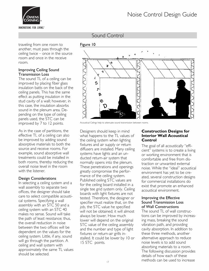
traveling from one room to another, must pass through the ceiling twice – once in the source room and once in the receive room.
Improving Ceiling Sound Transmission Loss The sound TL of a ceiling can be improved by placing fi ber glass insulation batts on the back of the ceiling panels. This has the same effect as putting insulation in the stud cavity of a wall; however, in this case, the insulation absorbs sound in the plenum area. De-pending on the type of ceiling panels used, the STC can be improved by 7 to 12 points.
As in the case of partitions, the effective TL of a ceiling can also be improved by adding sound absorptive materials to both the source and receive rooms. For example, sound absorptive wall treatments could be installed in both rooms, thereby reducing the overall noise level in the room with the listener.
Design Considerations In selecting a ceiling system and a wall assembly to separate two offi ces, the designer should take care to select compatible acousti-cal systems. Specifying a wall assembly with an STC 50 and a ceiling system with an STC 40 makes no sense. Sound will take the path of least resistance; thus, the overall reduction in noise between the two offi ces will be dependent on the values for the ceiling system. Little, if any, sound will go through the partition. A ceiling and wall system with approximately the same TL values should be selected.
Designers should keep in mind what happens to the TL values of the ceiling system when lighting fi xtures and air supply or return diffusers are installed. Many ceiling systems have lights and an un-ducted return-air system that normally opens into the plenum. These penetrations and openings greatly compromise the perfor-mance of the ceiling system. Published ceiling STC values are for the ceiling board installed in a single tee grid system only. Ceiling boards with light fi xtures are not tested. Therefore, the designer or specifi er must realize that, on the job, the STC value he specifi ed will not be obtained; it will almost always be lower. How much lower will depend on the original STC value of the ceiling assembly and the number and type of light fi xtures or return-air grills in-stalled. It could be lower by 10 or 15 STC points.
Construction Designs for Interior Wall Acoustical Control
The goal of all acoustically “effi -cient” systems is to create a living or working environment that is comfortable and free from dis-traction or unwanted external noise. While the “ideal” acoustical environment has yet to be cre-ated, several construction designs for commercial installations do exist that promote an enhanced acoustical environment.
Improving the Effective Sound Transmission Loss of Wall Constructions The sound TL of wall construc-tions can be improved by increas-ing mass, breaking the sound vibration path, and providing cavity absorption. In addition to these three methods, another alternative approach to reduce noise levels is to add sound absorbing materials to a room. The following discussion provides details of how each of these methods can be used to increase
Noise Control Design Guide
Figure 10
Acoustical Celings help to attenuate sound transmission between rooms.

Sound Control
18
Noise Control Design Guide
Table 2Sound Transmission Loss of Exterior Walls
Exterior Finish Cavity Insulation Resilient Channel STC Wall Construction DetailsWood Siding None
Fiber glass insulation 3½ " R11 kraft facedNoneFiber glass insulation 3½ " R11 kraft faced
NoNoYesYes
37394347
FramingSheathingSidingInterior
2" x 4" wood studs, 16" o.c.½ " wood fi berboard insulation nailed to studs5/8" x 10" redwood nailed through sheathing into studs½ " gypsum board screwed to studs or to metal resilient
channels which were attached to the studs
Stucco Fiber glass insulation 3½ " R11 kraft facedNoneFiber glass insulation 3½ " R11 kraft faced
NoYesYes
464957
FramingSheathingStucco
Interior
2" x 4" wood studs, 16" o.c.NoneNo. 15 felt building and 1" wire mesh nailed to studs.Stucco
applied in 3 coats to 7/8" total thickness. Dry weight of stucco 7.9 lb/sq ft.
½ " gypsum board screwed to studs or resilient channel
Brick Veneer Fiber glass insulation 3½ " R11 kraft facedNoneFiber glass insulation 3½ " R11 kraft faced
NoYesYes
565458
FramingSheathingBrick
2" x 4" wood studs, 16" o.c.¾ " wood fi berboard insulationStandard face brick 3½ " wide, spaced out ½ " from sheathing
with metal ties nailed through sheathing into studs. Dry weight of brick and mortar 41 lb/sq ft.
Concrete Block None No 45
Interior ½ " gypsum board screwed to studs or resilient channel
Taken from the U.S. Department of Commerce National Bureau of Standards Building Science Series 77.STC ratings of 50 or more are recognized as meeting the testing requirements set forth in Uniform Building Code Appendix, Chapter 35, ICBO ES Evaluation Report No. 2976P.
Table 3Sound Transmission Loss of Exterior Doors
Door Weather Strip Normally Closed STC Door Construction DetailsWood, fl ush solid core Brass 27 Width
Weight1¾ "78 lb, 3.9 lb,/sq. ft.
Wood, fl ush solid core Plastic 27
Steel, fl ush Magnetic 27 WidthFacesCoreWeight
1¾ "0.028" steel, separated by plastic perimeter stripRigid polyurethane, 2 to 2½ lb./cu ft., foamed in place64 lb., 3.2 lb./sq. ft.
Table 4Sound Transmission Loss of Windows
Material Type Size Glazing1 Sealed STC Locked STC Unlocked STCWood Double hung 3' x5' ss
ss-dds
ds-din-7/16"
2929293028 26
23
22
Fixed Picture 6' x 5' ss-dds
in-1"
282934 STC STC
Wood-Plastic Double hung ssin-3/8"
2926
2626
2625
Storm sash dsin-3/8"
3028
2724
fi xed casement ds 31
Operable casment ds 30 22
Sliding glass door lam-3/16" 31 26 26
Aluminum Sliding ss 28 24
Operable Casement ds 31 21 17
Single hung in-7/16" 30 27 25
Single Pane ¼ " lamintaed glass 34
1ss = single strength, ds = double strength, d = divided lights, in = insulating glass of indicated overall thickness, lam = laminated safety glass of indicated overall thicknessTaken from the U.S. Department of Commerce National Bureau of Standards Building Science Series 77

Sound Control
19
the effective acoustical perfor-mance of walls.
Increasing Mass Heavier materials block sound better than light materials. For example, adding another layer of gypsum wallboard provides increased sound TL.
As a general rule, every doubling of the weight of the wall increases sound TL by an additional 5-6 dBs. Heavier walls, however, are obviously not the most economi-cal or most aesthetic solution to sound control requirements.
Breaking Vibration Path Walls transmit sound most effectively when they can transmit vibrations from one face to another through structural ele-ments such as metal or wood studs. Anything that can be done to interfere with the transmission of vibration between one wall surface and the other will help reduce sound transmission. An effective technique is to stagger wood studs, reducing sound transmission through them.
Metal studs are more resilient than wood studs and reduce the transmission of vibrations be-tween one wall surface and the other. In wood stud constructions, resilient metal channels can be used between the gypsum wall board and the stud to break the vibration path.
Cavity Absorption The sound TL of a wall can also be increased by fi lling the wall cavity with sound absorbing materials such as fi ber glass building insulation. The use of fi ber glass insulation in a typical
metal stud wall, staggered wood stud or other wall with isolated faces, can increase sound TL by about 8 dBs – an improvement that is readily noticeable.
The key point to remember, how-ever, is that the insulation is performing a sound absorption function in the stud cavity. It does not add any signifi cant weight or mass to the partition. Within a range of densities from 0.6 to 6.0 pounds per cu. ft. for cavity insulation, there is no signifi cant difference in the sound absorbing properties. Therefore, the sound absorption effectiveness of an insulation should be the key to its selection, not density. (See “The Density Myth.”)
Adding Sound Absorbing Materials To Source and Receive Areas Another method of increasing the effective sound TL between two rooms is to add sound absorbing materials to each room. By doing this, the overall noise level in each room is reduced, which results in a corresponding reduction of the sound level in any adjacent area.
By adding sound absorbing materials to both the source and receive room, one can obtain a signifi cant reduction of the noise level in the receive room. The net effect is a signifi cant reduction in intruding noise, with no change to the separating partition.
Detail Design and Construction Considerations The effective acoustical perfor-mance of walls can be greatly affected by a number of design and construction details. These details include sealing the perim-
Noise Control Design Guide
A
B
Figure 11
The addition of a layer of gypsum board to one surface effectively increases wall mass.A- ¾ " Gypsum Board Double LayerB- ¾ " Gypsum Board Single Layer
A
B
C
Figure 12
Resilient channels over wood studs break the vibrating path, helping to increase sound transmission loss.A- ¾ " Gypsum Board Single LayerB- 3½ " Fiber Glass Wood Framing Batt InsulationC- Resilient Channel
A
B
C
Figure 13
Insulating wall cavities noticeably improves sound transmis-sion loss by providing cavity absorption.A- ¾ " Gypsum Board Double LayerB- ¾ " Gypsum Board Single LayerC- 3½ " Fiber Glass Sound Attenuation Batt

Sound Control
20
eter of walls, construction details at wall intersections, size and placement of windows, and the location and proper installation of doors, electrical outlets, ducts and mechanical equipment. The following discussion provides some important suggestions to insure acoustical performance.
Perimeter Sealing An air seal should be used around the perimeter of the wall to effect a proper acoustical seal. A non-hardening, permanently resilient caulking such as butyl rubber-based compound is recommend-ed for both sides of the partition at applicable locations, such as at the bottom and top plates. Joint compound and tape will seal effectively in corners if multiple layers of wallboard are properly staggered.
Figure 14 provides construction details for framing sound insulating walls at corners and intersections.
Doors Where optimum noise control is desired, solid wood core doors or metal doors should be used. Door tops and sides should be gasketed with a soft type weather stripping. Use of threshold clo-sures at the bottom of the door or air seals will reduce sound transmission.
Sliding doors should be avoided where optimum noise control is desired. Doors opening upon hallways should not open across from one another.
Windows Windows normally have lower TL values than the surrounding wall. Therefore, it is advantageous to
reduce window area for increased noise control.
Additional measures that can be taken to increase noise control are the reduction of windows facing noisy areas and the separa-tion of windows to reduce cross-talk. Give consideration to the use of thick or insulated glass (as well as double glazing) to help reduce sound transmission. Weather stripping windows will assure that they close tight, and thus, reduce the transmission of outside sound sources.
Electrical Electrical installations must be given due consideration to assure they do not create a noise control problem. Light switches and outlets should not be constructed back-to-back. Ceiling fi xtures should be surface mounted and openings around boxes should be sealed airtight.
Electrical distribution panels, as well as telephones, bells, inter-coms or audio built-ins should be installed on well-insulated interior walls only, and never on party or corridor walls.
Each living/working unit (when possible) should be wired as a complete unit, and vibrating equipment should be connected with fl exible wiring.
Plumbing Various acoustical design consid-erations come into play when installing plumbing.
Pipe runs should be designed with swing arms so expansion and contraction can occur without binding, thus eliminating any
unwanted sound. Also, piping should be isolated from surround-ing structures with resilient mounts. Air chambers should be provided at each outlet to elimi-nate water hammer due to the abrupt stopping of fl owing water, and consideration should be given to oversized pipes and reduced water pressure.
Noise Control Design Guide
Wood Stud with Resilient Channels
Corner Detail
Resilient Channel
Stagger Joints
Tape and Seal
Fiber Glass Insulation
Stagger Joints
Tape and Seal
Resilient Channel
Double Layer
Gypsum Board
Wood Plate
Staggered Stud Walls
Corner DetailDouble Layer Gypsum Board
Fiber Glass Insulation
Stagger Joints Tape and Seal
Intersection Detail
Stagger Joints
Tape and Seal
Figure 14
Framing of Sound Insulation Walls at Corners and Intersections.

Sound Control
21
Installation of fi xtures back-to-back should be avoided. In all cases, openings made in walls and fl oor surfaces should be caulked to insure optimum acoustical integrity.
Ducts Duct design should be given special consideration when planning the layout of a new or retrofi t commercial construction, since ducts can easily transmit sound.
Installation of suffi ciently thick metal ducts, lined with sound attenuating duct liner insulation, and the use of duct wrap materi-als will reduce sidewall transmis-sion of unwanted sound, as well as reduce fan noise in the duct. The use of quality, quiet appli-ances, air conditioners and fur-naces with well-balanced motors and fans is recommended to reduce duct-carried noise.
In addition to offering noise-absorbing, energy-saving thermal barriers, Owens Coming offers a variety of duct wraps, liners and
other systems that effectively reduce duct noise.
Equipment NoiseBefore buying large equipment, be sure to inquire about equipment noise levels. Insist on quiet units.
Whenever possible, isolate furnaces, air conditioners and other HVAC units away from “quiet” areas. Enclose these units in a well-insulated room, and utilize a solid core door when equipment rooms are accessible to building interiors.
Also, when installing equipment likely to vibrate, use vibration isolators.
Vertical ducts or ventilation risers mounted on the exterior of buildings frequently are the cause of noise complaints. Such devices often rattle in windy areas or snap, crackle and pop (owing to thermal expansion and contrac-tion) with outdoor temperature variation. Further, the outdoor noise of aircraft, traffi c, etc. are easily transmitted by the thin-walled duct and carried into the
building interior. All exterior ductwork should be of double-wall construction with acoustical lining and silencers. Staggered Wood Studs
Noise Control Design Guide
Plugs or Switches
36” min.
Wall Fixtures
24” min.
Figure 15
Caulk all openings to insure acoustical integrity.
A
B
C
D
Figure 16
Caulk all openings to insure acoustical integrity.
Acoustic Lining
Flex Boot
Air Conditioning
Equipment
Spring Mount
Suspended Ceiling
Rubber GasketsLow Frequency
Sound Absorber
Diffuser
Roof Slab
Double-Wall Duct
Figure 17
When possible, noisy equipment should be acoustically enclosed.

Sound Control
22
Wall System Selection Chart
For Wood Stud Walls
Staggered Wood Studs
LayerSTC
Test No. STC Construction DescriptionFire
RatingFire Test
DL W4869 55 Staggered wood studs 24" o.c.; double layer ½ " type "x" gypsum drywall each side; one thickness, 3½ " thick Wood Framing Batt Insulation
1 hr.1 UL U309
DL W4669 52 Staggered wood studs 24" o.c.; double layer ½ " type "x" gypsum drywall each side; no insulation
1 hr.1 UL U309
UB W4769 53 Staggered wood studs 24" o.c.; double layer ½ " type "x" gypsum drywall one side, single layer other side; one thickness, 3½ " thick Wood Framing Batt Insulation
N.A. —
UB W4569 47 Staggered wood studs 24" o.c.; double layer ½ " type "x" gypsum drywall one side, single layer other side; one thickness, no insulation
N.A. —
SL OC5FC 51 Staggered wood studs 16" o.c.; single layer ½ " type "x" gypsum drywall each side; two thicknesses, 3½ " thick Wood Framing Batt Insulation
1 hr. OSU 4970
SL W01486 51 Staggered wood studs 16" o.c.; single layer ½ " type "x" gypsum drywall each side; one thickness, 3½ " thick Wood Framing Batt Insulation
N.A. —
SL OC3FC 39 Staggered wood studs 16" o.c.; single layer ½ " type "x" gypsum drywall each side; no isulation
N.A. —
SL W5769 46 Staggered wood studs 24" o.c.; double layer 5/8" type "x" gypsum drywall each side; one thickness, 3½ " thick Wood Framing Batt Insulation
1 hr.1 UL U305
SL W5869 43 Staggered wood studs 24" o.c.; double layer 5/8" type "x" gypsum drywall each side; no isulation
1 hr.1 UL U305
DL=double layers of gypsum drywall UB=unbalanced layers of gypsum drywall SL=single layers of gypsum drywall1Rating is estimated from tests using thinner assemblies of fewer layers of gypsum drywall. Specifi c test references are available and will be provided upon request. Owens Corning Metal Framing Batts and Wood Framing Batts are manufactured from fi ber glass insulation.
Single Wood Studs with Resilient Channel
LayerSTC
Test No. STC Construction DescriptionFire
RatingFire Test
DL W0569 56 Single wood studs 16" o.c.; resilient channel; double layer ½ " type "x" gypsum drywall each side; one thickness, 3½ " thick Wood Framing Batt Insulation
1 hr.1 OSU T-3127
DL W1369 52 Single wood studs 16" o.c.; resilient channel; double layer ½ " type "x" gypsum drywall each side; one thickness, no insulation
1 hr.1 UL U305
UB W0669 52 Single wood studs 16" o.c.; resilient channel; single layer ½ " type "x" gypsum drywall one side, double layer other side; one thickness, 3½ " thick Wood Framing Batt Insulation
N.A. —
UB W1469 44 Single wood studs 16" o.c.; resilient channel; single layer ½ " type "x" gypsum drywall one side, double layer other side; one thickness, no insulation
N.A. —
SL WP32302 50 Single wood studs 16" o.c.; resilient channel; single layer 5/8" type "x" gypsum drywall each side; one thickness, 3½ " thick Wood Framing Batt Insulation
1 hr.1 OSU T-3127
SL OCF431 40 Single wood studs 16" o.c.; resilient channel; single layer 5/8" type "x" gypsum drywall each side; one thickness, no insulation
1 hr.1 UL U305
SL W0769 46 Single wood studs 16" o.c.; resilient channel; single layer ½ " type "x" gypsum drywall each side; one thickness, 3½ " thick Wood Framing Batt Insulation
N.A. —
SL W0969 39 Single wood studs 16" o.c.; resilient channel; single layer ½ " type "x" gypsum drywall each side; one thickness, no insulation
N.A. —
DL=double layers of gypsum drywall UB=unbalanced layers of gypsum drywall SL=single layers of gypsum drywall1Rating is estimated from tests using thinner assemblies of fewer layers of gypsum drywall. Specifi c test references are available and will be provided upon request. 2Listed in the Gyspum Association Fire Resistance Design ManualOwens Corning Metal Framing Batts and Wood Framing Batts are manufactured from fi ber glass insulation.

Sound Control
23
Wall System Selection Chart
For Wood Stud Walls
Single Wood Studs
LayerSTC
Test No. STC Construction DescriptionFire
RatingFire Test
DL W2569 45 Single wood studs 16" o.c.; double layer ½ " type "x" gypsum drywall each side; one thickness, 3½ " thick Wood Framing Batt Insulation
1 hr.1 UL U305
UB W4769 53 Single wood studs 16" o.c.; double layer ½ " type "x" gypsum drywall one side, single layer other side; one thickness, 3½ " thick Wood Framing Batt Insulation
N.A. —
UB W2269 38 Single wood studs 16" o.c.; double layer ½ " type "x" gypsum drywall one side, single layer other side; no insulation
N.A. —
SL W2069 39 Single wood studs 16" o.c.; single layer ½ " type "x" gypsum drywall each side; one thickness, 3½ " thick Wood Framing Batt Insulation
N.A. —
SL W2169 35 Single wood studs 16" o.c.; single layer ½ " type "x" gypsum drywall each side; no insulation
N.A. —
SL W5769 46 Single wood studs 16" o.c.; single layer 5/8" type "x" gypsum drywall each side; one thickness, 3½ " thick Wood Framing Batt Insulation
1 hr.1 UL U305
SL W5869 43 Single wood studs 16" o.c.; single layer 5/8" type "x" gypsum drywall each side; no insulation
1 hr.1 UL U305
DL=double layers of gypsum drywall UB=unbalanced layers of gypsum drywall SL=single layers of gypsum drywall1Rating is estimated from tests using thinner assemblies of fewer layers of gypsum drywall. Specifi c test references are available and will be provided upon request. Owens Corning Metal Framing Batts and Wood Framing Batts are manufactured from fi ber glass insulation.
Double Wood Studs
LayerSTC
Test No. STC Construction DescriptionFire
RatingFire Test
DL W01480 64 Double wood studs 16" o.c.; double layer ½ " type "x" gypsum drywall each side; one thickness, 3½ " thick Wood Framing Batt Insulation
1 hr.1 UL U305
DL W4069 62 Double wood studs 16" o.c.; double layer 5/8" type "x" gypsum drywall each side; one thickness, 2½ " thick Wood Framing Batt Insulation
2 hr. WP 38202
DL W01580 54 Double wood studs 16" o.c.; double layer ½ " type "x" gypsum drywall each side; one thickness, no insulation
1 hr.1 UL U305
UB W0180 60 Double wood studs 16" o.c.; double layer ½ " gypsum drywall one side, single layer other side; two thicknesses, 3½ " thick Wood Framing Batt Insulation
1 hr.1 OSU 4936
UB W01180 57 Double wood studs 16" o.c.; double layer ½ " type "x" gypsum drywall one side, single layer other side; one thickness, 3½ " thick Wood Framing Batt Insulation
N.A. —
UB W00980 48 Double wood studs 16" o.c.; double layer ½ " type "x" gypsum drywall one side, single layer other side; one thickness, no insulation
N.A. —
SL W2869 59 Double wood studs 16" o.c.; double layer ½ " type "x" gypsum drywall each side; two thicknesses, 3½ " thick Wood Framing Batt Insulation
1 hr.1 OSU 4936
SL W2969 56 Double wood studs 16" o.c.; single layer ½ " type "x" gypsum drywall each side; one thickness, 3½ " thick Wood Framing Batt Insulation
N.A. —
SL W3469 47 Double wood studs 16" o.c.; single layer ½ " type "x" gypsum drywall each side; no insulation
N.A. —
SL OCF448 56 Double wood studs 16" o.c.; single layer 5/8" type "x" gypsum drywall each side; one thickness, 3½ " thick Wood Framing Batt Insulation
1 hr.1 UL U305
SL W4369 45 Double wood studs 16" o.c.; single layer 5/8" type "x" gypsum drywall each side; no insulation
1 hr.1 UL U305
SL W02985 60 Double wood studs 24" o.c.; single layer5/8" type "x" gypsum drywall each side; two thicknesses, 3½ " thick Wood Framing Batt Insulation
1 hr. UL U341
SL W03685 43 Double wood studs 24" o.c.; single layer 5/8" type "x" gypsum drywall each side; no insulation
1 hr. UL U309
DL=double layers of gypsum drywall UB=unbalanced layers of gypsum drywall SL=single layers of gypsum drywall1Rating is estimated from tests using thinner assemblies of fewer layers of gypsum drywall. Specifi c test references are available and will be provided upon request. Owens Corning Metal Framing Batts and Wood Framing Batts are manufactured from fi ber glass insulation.

Sound Control
24
Wall System Selection Chart
For Metal Stud Walls
Single Layer Walls with Resilient Channel
LayerSTC
Test No. STC Construction DescriptionFire
RatingFire Test
SL RAL-TL89-293 55 Single layer wall, resilient channel; 5/8" type "x" gypsum drywall; 6" steel stud; one thickness, 6¼ " thick Metal Framing Batt Insulation
1 hr.1 UL U465
SL RAL-TL90-344 54 Single layer wall, resilient channel; 5/8" type "x" gypsum drywall; 35/8" steel stud; one thickness, 6¼ " thick Metal Framing Batt Insulation
1 hr. UL U465
DL=double layers of gypsum drywall UB=unbalanced layers of gypsum drywall SL=single layers of gypsum drywall1Rating is estimated from tests using thinner assemblies of fewer layers of gypsum drywall. Specifi c test references are available and will be provided upon request. Owens Corning Metal Framing Batts and Wood Framing Batts are manufactured from fi ber glass insulation.
Chase Walls
LayerSTC
Test No. STC Construction DescriptionFire
RatingFire Test
DL W1268 60 Chase wall; double layer 5/8" type "x" gypsum drywall; 15/8" steel stud; three thicknesses, 3½ " thick Sound Attenuation Batt Insulation
2 hr. UL U436
DL RAL-TL90-350 57 Chase wall; double layer 5/8" type "x" gypsum drywall; 15/8" steel stud; three thicknesses, 3½ " thick Sound Attenuation Batt Insulation
2 hr. UL U420
SL RAL-TL90-349 53 Chase wall; 5/8" type "x" gypsum drywall; 15/8" steel stud; one thickness, 3½ " thick Metal Framing Batt Insulation, or Sound Attenuation Batt Insulation
1 hr. UL U420
SL W1068 55 Chase wall; ½ " type "x" gypsum drywall; 15/8" steel stud; three thicknesses, 3½ " thick Metal Framing Batt Insulation, or Sound Attenuation Batt Insulation
N.A. —
SL W468 52 Chase wall; ½ " type "x" gypsum drywall; 15/8" steel stud; one thickness, 3½ " thick Metal Framing Batt Insulation, or Sound Attenuation Batt Insulation
N.A. —
SL W368 42 Chase wall; ½ " type "x" gypsum drywall; 15/8" steel stud; no insulation N.A. —
DL=double layers of gypsum drywall UB=unbalanced layers of gypsum drywall SL=single layers of gypsum drywall1Rating is estimated from tests using thinner assemblies or fewer layers of gypsum drywall. Specifi c test references are available and will be provided upon request. Owens Corning Metal Framing Batts and Wood Framing Batts are manufactured from fi ber glass insulation.
Shaftwalls
LayerSTC
Test No. STC Construction DescriptionFire
RatingFire Test
UB NGC-26262 47 Unbalanced wall, 1" shaftliner one side, 2 layers ½ " type "x" gypsum drywall other side; 2½ " I-studs, 1½ " Shaftwall Insulation
2 hr. WP 70801
UB NGC-26172 45 Unbalanced wall, 1" shaftliner and 1 layer ½ " type "x" gypsum drywall one side, 1 layer ½ " type "x" gypsum drywall other side; 2½ " I-studs, 1½ " Shaftwall Insulation
2 hr. WP 70791
SL NGC-25422 42 Single layer wall, 1" shaftliner one side, 5/8" type "x" gypsum drywall other side; 2½ " I-studs, 1½ " Shaftwall Insulation
1 hr. FM WP-7552
DL=double layers of gypsum drywall UB=unbalanced layers of gypsum drywall SL=single layers of gypsum drywall1Listed in the Gyspum Association Fire Resistance Design Manual.2Reprinted with permission of National Gypsum Company.Owens Corning Metal Framing Batts and Wood Framing Batts are manufactured from fi ber glass insulation.

Sound Control
25
Wall System Selection Chart
For Metal Stud Walls
Unbalanced Walls with Resilient Channel
LayerSTC
Test No. STC Construction DescriptionFire
RatingFire Test
UB RAL-TL89-285 60 Unbalanced wall, 5/8" type "x" gypsum drywall; single layer one side; double layer and resilient channel other side; 6" steel stud; one thickness, 6¼ " thick Metal Framing Batt Insulation
1 hr.1 UL U465
UB RAL-TL90-345 58 Unbalanced wall, 5/8" type "x" gypsum drywall; single layer and resilient channel one side; double layer other side; 6" steel stud; one thickness, 3½ " thick Metal Framing Batt Insulation, or Sound Attenuation Batt Insulation
1 hr.1 UL U465
DL=double layers of gypsum drywall UB=unbalanced layers of gypsum drywall SL=single layers of gypsum drywall1Rating is estimated from tests using thinner assemblies of fewer layers of gypsum drywall. Specifi c test references are available and will be provided upon request. Owens Corning Metal Framing Batts and Wood Framing Batts are manufactured from fi ber glass insulation.
Single Layer Walls
LayerSTC
Test No. STC Construction DescriptionFire
RatingFire Test
SL RAL-TL89-288 51 Single layer wall, 5/8" type "x" gypsum drywall; 6" steel stud; one thickness, 6¼ " thick Metal Framing Batt Insulation
1 hr. UL U465
SL RAL-TL89-157 50 Single layer wall, 5/8" type "x" gypsum drywall; 35/8" steel stud; one thickness, 3½ " thick Metal Framing Batt Insulation or Sound Attenuation Batt Insulation
1 hr. UL U465
SL W03582 48 Single layer wall, 5/8" type "x" gypsum drywall; 35/8" steel stud; one thickness, 2½ " thick Sound Attenuation Batt Insulation
1 hr. UL U465
SL W03182 43 Single layer wall, 5/8" type "x" gypsum drywall; 35/8" steel stud; no insulation 1 hr. UL U465
SL RAL-TL87-394 48 Single layer wall, ½ " type "x" gypsum drywall; 35/8" steel stud; one thickness, 3½ " thick Firecore 60® Type FB Sound Attenuation Batt Insulation
1 hr. UL U468
SL RAL-T87-392 47 Single layer wall, ½ " type "x" gypsum drywall; 35/8" steel stud; one thickness, 3½ " thick Metal Framing Batt Insulation or Sound Attenuation Batt Insulation
N.A. —
SL W03682 44 Single layer wall, ½ " gypsum drywall; 35/8" steel stud; one thickness, 2½ " thick Sound Attenuation Batt Insulation
N.A. —
SL W00582 36 Single layer wall, ½ " gypsum drywall; 35/8" steel stud; no insulation N.A. —
SL W05182 47 Single layer wall, 5/8" type "x" gypsum drywall; 2½ " steel stud; one thickness, 2½ " thick Sound Attenuation Batt Insulation
1 hr. UL U468
SL W05482 40 Single layer wall, 5/8" type "x" gypsum drywall; 2½ " steel stud; no insulation 1 hr. SP 13402
SL RAL-TL91-306 45 Single layer wall, ½ " type "x" gypsum drywall; 2½ " steel stud; one thickness, 3½ " thick Firecore 60 Type FB Sound Attenuation Batt Insulation
1 hr. UL U468
SL RAL-TL91-309 44 Single layer wall, ½ " gypsum drywall; 2½ " steel stud; one thickness, 2½ " thick Sound Attenuation Batt Insulation
N.A. —
SL W04382 34 Single layer wall, ½ " gypsum drywall; 2½ " steel stud; no insulation N.A. —
DL=double layers of gypsum drywall UB=unbalanced layers of gypsum drywall SL=single layers of gypsum drywall1Listed in the Gyspum Association Fire Resistance Design Manual.Owens Corning Metal Framing Batts and Wood Framing Batts are manufactured from fi ber glass insulation.

Sound Control
26
Wall System Selection Chart
For Metal Stud Walls
Double Layer Walls
LayerSTC
Test No. STC Construction DescriptionFire
RatingFire Test
DL W02584 58 Double layer wall; 5/8" type "x" gypsum drywall; 35/8" steel stud; one thickness, 3½ " thick Metal Framing Batt Insulation or Sound Attenuation Insulation
2 hr. UL U411
DL W02982 52 Double layer wall; 5/8" type "x" gypsum drywall; 35/8" steel stud; no insulation 2 hr. UL U411
DL W02184 56 Double layer wall; ½ " type "x" gypsum drywall; 35/8" steel stud; one thickness, 3½ " thick Metal Framing Batt Insulation or Sound Attenuation Insulation
2 hr. WP 15451
DL W-780 50 Double layer wall; 5/8" type "x" gypsum drywall; 35/8" steel stud; no insulation 2 hr. WP 15451
DL W02784 57 Double layer wall; 5/8" type "x" gypsum drywall; 2½ " steel stud; one thickness, 2½ " thick Sound Attenuation Insulation
2 hr. UL U411
DL W03084 54 Double layer wall; ½ " type "x" gypsum drywall; 2½ " steel stud; one thickness, 2½ " thick Sound Attenuation Insulation
2 hr. WP 1545
DL W04582 45 Double layer wall; ½ " type "x" gypsum drywall; 2½ " steel stud; no insulation 2 hr. WP 15451
DL=double layers of gypsum drywall UB=unbalanced layers of gypsum drywall SL=single layers of gypsum drywall1Listed in the Gyspum Association Fire Resistance Design Manual.Owens Corning Metal Framing Batts and Wood Framing Batts are manufactured from fi ber glass insulation.
Unbalaced Walls
LayerSTC
Test No. STC Construction DescriptionFire
RatingFire Test
UB W02484 55 Unbalanced wall; 5/8" type "x" gypsum drywall; 35/8" steel stud; one thickness, 3½ " thick Metal Framing Batt Insulation or Sound Attenuation Batt Insulation
1 hr.1 UL U465
UB W03082 47 Unbalanced wall; 5/8" type "x" gypsum drywall; 35/8" steel stud; no insulation 1 hr.1 UL U465
UB W02284 52 Unbalanced wall; ½ " type "x" gypsum drywall; 35/8" steel stud; one thickness, 3½ " thick Metal Framing Batt Insulation or Sound Attenuation Batt Insulation
N.A. —
UB W00682 41 Unbalanced wall; ½ " gypsum drywall; 35/8" steel stud; no insulation N.A. —
UB W02884 52 Unbalanced wall; 5/8" type "x" gypsum drywall; 35/8" steel stud; one thickness, 3½ " thick Metal Framing Batt Insulation or Sound Attenuation Batt Insulation
1 hr.1 UL U494
UB W05382 44 Unbalanced wall; 5/8" type "x" gypsum drywall; 2½ " steel stud; no insulation 1 hr.1 WP 13402
UB W02984 50 Unbalanced wall; ½ " type "x" gypsum drywall; 2½ " steel stud; one thickness, 2½ " thick Sound Attenuation Batt Insulation
N.A. —
UB W04482 39 Unbalanced wall; ½ " gypsum drywall; 2½ " steel stud; no insulation N.A. —
DL=double layers of gypsum drywall UB=unbalanced layers of gypsum drywall SL=single layers of gypsum drywall1Rating is estimated from tests using thinner assemblies or fewer layers of gypsum drywall. Specifi c test references are available and will be provided upon request. 2Listed in the Gyspum Association Fire Resistance Design Manual.Owens Corning Metal Framing Batts and Wood Framing Batts are manufactured from fi ber glass insulation.

Sound Control
27
Test Your Knowledge
1. Does the density of insulation affect the acoustical performance of a wall system? A. Yes B. No
2. Does the thickness of the insulation affect the acoustical performance of a wall system? A. Yes B. No
3. The measure of sound pressure or intensity is called a(n): A. Decibel B. Frequency C. Impact
4. Unwanted sound, regardless of the source is called: A. Heavy metal B. Noise C. Vibrations
5. The ear is most sensitive to sound around __ Hz. A. 5,000 Hz. B. 2,000 Hz. C. 1,000 Hz.
6. The amount of sound energy absorbed by an object is expressed in terms of: A. Sound Absorption Coeffi cient B. Noise Reduction Coeffi cient C. Sound Transmission Class
7. A material with a sound absorption coeffi cient of .85 means that ____% of the sound energy striking the materials is refl ected. A. 85% B. 15% C. 50%
8. The single number rating system describing the sound absorbing power of a material is defi ned as the: A. Noise Reduction Coeffi cient B. Sound Transmission Class C. Sound Absorption Coeffi cient
9. Any material defi ned as a sound absorber must have an NRC value of _______ or greater. A. 0.20 B. 0.30 C. 0.40
10. The human ear cannot perceive acoustical differences between two sound absorbers whose NRC values differ by ________: A. 0.05 B. 0.80 C. 0.85
11. Can the human ear detect an NRC difference of .80 and .90 of two different materials? A. Yes B. No
12. The NRC of unpainted concrete block is: A. .27 B. .44 C. .35
13. The ability of a material or system to block or attenuate the transmission of sound from one area to another is measured by: A. Noise Gain B. Transmission Loss C. Sound Attenuation
14. The test method used by all laboratories in determining sound transmission loss is ASTM: A. E90 B. C124 C. D356
15. The ___________is a method of rating the air-borne sound transmission performance of a wall or ceiling assembly at different frequencies by means of a single number. A. Noise Reduction Coeffi cient B. Sound Transmission Class C. Hz. rating
16. How can the STC of a ceiling be improved? A. By placing fi ber glass insulation batts on the backs of the ceiling panels B. By drilling holes into the ceiling panels C. By using a white noise machine

Sound Control
28
Test Your Knowledge
17. Typically, when fi ber glass insulation is placed on top of an existing commercial ceiling, the STC can be improved by 7 to __ points. A. 11 B. 12 C. 15
18. A difference in STC rating of 3 points is audible to the human ear. A. Yes B. No
19. Different laboratories testing for STC often get different readings when using the same assemblies. A. Yes B. No
20. What is the STC rating of a wood sided exterior wall with 3 ½ " R-11 insulation? (No resilient channel) A. 21 B. 29 C. 39
21. As a general rule, doubling the weight of a wall system increases sound transmission loss by an additional 5-6 dBs. A. Yes B. No
22. Resilient channel reduces the effi ciency of the sound reduction of a wall system. A. Yes B. No
23. Windows in walls typically have a lower transmission loss value than the surrounding wall. A. Yes B. No
24. When designing a wall for increased acoustical performance and absorption, minimizing doors, windows and electrical outlets in the wall is benefi cial. A. Yes B. No
25. The use of fi ber glass building insulation in a typical metal stud wall, staggered wood stud wall, or other wall with isolated faces can in-crease sound transmission loss by about 8 dBs. A. Yes B. No


OWENS CORNING INSULATING SYSTEMS, LLCONE OWENS CORNING PARKWAYTOLEDO, OHIO, USA 43659
1-800-GET-PINK™
www.owenscorning.com
Pub. No. 22322-C. Printed in U.S.A. January 2007. THE PINK PANTHER™ & ©1964–2007 Metro-Goldwyn-Mayer Studios Inc. All Rights Reserved. The color PINK is a registered trademark of Owens Corning. ©2007 Owens Corning.