ITW-Performance-Polymers-1469124.pdf - BuildSite
64
Industrial Grouts, Polymers & Foundation Systems Engineering
-
Upload
khangminh22 -
Category
Documents
-
view
1 -
download
0
Transcript of ITW-Performance-Polymers-1469124.pdf - BuildSite

Industrial Grouts, Polymers & Foundation Systems
En
gin
ee
rin
g

This Page Left Intentionally Blank

130 Commerce Drive Montgomeryville, PA 18936
P: 215.855.8450 F: 215.855.4688
Printing this Manual If you would like to print a copy of this Technical Manual, please review the following instructions: This manual is already formatted for printing on the front and back sides of each page. Color Printer When printing from a color printer, enter the properties dialog box for your printer and select the appropriate settings for two-sided printing and follow be sure to follow your printer’s instructions for two-sided printing. Professional Print Shops You may also take this pdf file on CD or flash drive to a print shop to make copies. Be sure to instruct the attendant to provide the following: • Designate the number of manual sets desired. • Print color copies • Two-sided printing • If you plan to use your own three-ring binder, request the docu-
ment be three-hole punched only
• If you would like the print shop to bind the document with a front and back cover, request clear plastic covers front and back and coil bound.

This Page Left Intentionally Blank
Engineering Manual / Table of Contents
Industrial Grout, Polymers & Foundation Systems
Section 1 - Machinery Basics 1
Definitions
Section 2 – Mathematics 5
UnitsMetric PrefixesArea CalculationsVolume CalculationsConversions
Section 3 – Engineering 13
ForceStressStrainModulus of ElasticityTorqueThermal ExpansionStress ConcentrationFrictionCreep
Section 4 – Applications 26
ChocksGroutsExpansion JointsRepairsSecondary ContainmentFairing MaterialsBearings
Section 5 – Testing 33
ASTM
Section 6 - Chemistry 38

This Page Left Intentionally Blank

Industrial Grouts, Polymers & Foundation Systems
Secti
on
1/
Mach
inery
Basic
s

This Page Left Intentionally Blank

Engineering Manual
Industrial Grout, Polymers & Foundation Systems / Page 1
Section 1 / Machinery BasicsAlignment
The precise placing of one or more pieces of connected equipment relative to each other inorder to obtain dependable operation. Proper alignment insures any bearing surfaces will beloaded to design levels.
Base Plate
A metal fabrication on which machinery components are mounted. A pump base plate typicallyholds a motor, reduction gear, and the pump.
Bearing
A support for a mechanism that transmits force through motion. The motion can be rotating orreciprocating. Typical bearings can be journal (sleeve) bearings, ball bearings, or pads.
Journal Bearing Thrust Bearing Roller Bearings

Engineering Manual
Industrial Grout, Polymers & Foundation Systems / Page 2
Chock
A spacer that is placed between the mounting surface of a piece of machinery and thefoundation on which it sits. Chocks compensate for any differences between the elevations ofthe two surfaces and, as a result, each chock is individually manufactured to fit in its intendedlocation. Chocks can be made from a variety of materials with steel and poured epoxy beingthe most common.
Foundation
A supporting structure usually made from concrete poured in place or a metal fabrication.
Hold Down Bolts
Fasteners which secure a piece of machinery to a foundation. There are several types of holddown bolts.
Anchor Bolts
Bolts that are cast into a foundation. Machinery is set down over the exposed threadsand nuts are installed and tightened.
Fitted Bolts
Bolts installed in precisely machined holes so there is no possibility of the machinemoving in any side-to-side direction.
Clearance Bolts
Bolts installed in holes larger than the body of the bolt.
Indus
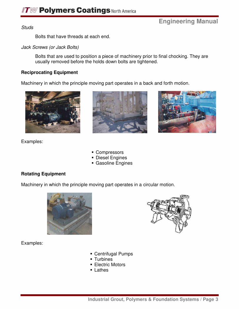
Studs
Bolts that have threads at e
Jack Screws (or Jack Bolts)
Bolts that are used to positusually removed before the
Reciprocating Equipment
Machinery in which the principle m
Examples:
Rotating Equipment
Machinery in which the principle m
Examples:
Enginee
Industrial Grout, Polymers & Foundation
t each end.
sition a piece of machinery prior to final chockithe holds down bolts are tightened.
e moving part operates in a back and forth mo
CompressorsDiesel EnginesGasoline Engines
e moving part operates in a circular motion.
Centrifugal PumpsTurbinesElectric MotorsLathes
ngineering Manual
on Systems / Page 3
cking. They are
motion.
Indus
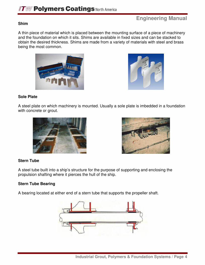
Shim
A thin piece of material which is pand the foundation on which it sits.obtain the desired thickness. Shimbeing the most common.
Sole Plate
A steel plate on which machinery with concrete or grout.
Stern Tube
A steel tube built into a ship’s strupropulsion shafting where it pierce
Stern Tube Bearing
A bearing located at either end of
Enginee
Industrial Grout, Polymers & Foundation
s placed between the mounting surface of a pisits. Shims are available in fixed sizes and canhims are made from a variety of materials with
ry is mounted. Usually a sole plate is imbedde
structure for the purpose of supporting and enclrces the hull of the ship.
of a stern tube that supports the propeller sha
ngineering Manual
on Systems / Page 4
piece of machinerycan be stacked toith steel and brass
ded in a foundation
nclosing the
shaft.

Industrial Grouts, Polymers & Foundation Systems
Secti
on
2/
Math
em
ati
cs

This Page Left Intentionally Blank

Engineering Manual
Industrial Grout, Polymers & Foundation Systems / Page 5
Section 2 / Mathematics
Units
English Metric
Length Inch Meter
Foot
Yard
Mile
Weight Pound Newton
Ounce
Ton
Mass Slug Gram
Capacity Gallon Liter
Temperature Fahrenheit Centigrade
Pressure Lb / in² Kg / cm²
Pascal
Bar
Engineering Manual
Industrial Grout, Polymers & Foundation Systems / Page 6
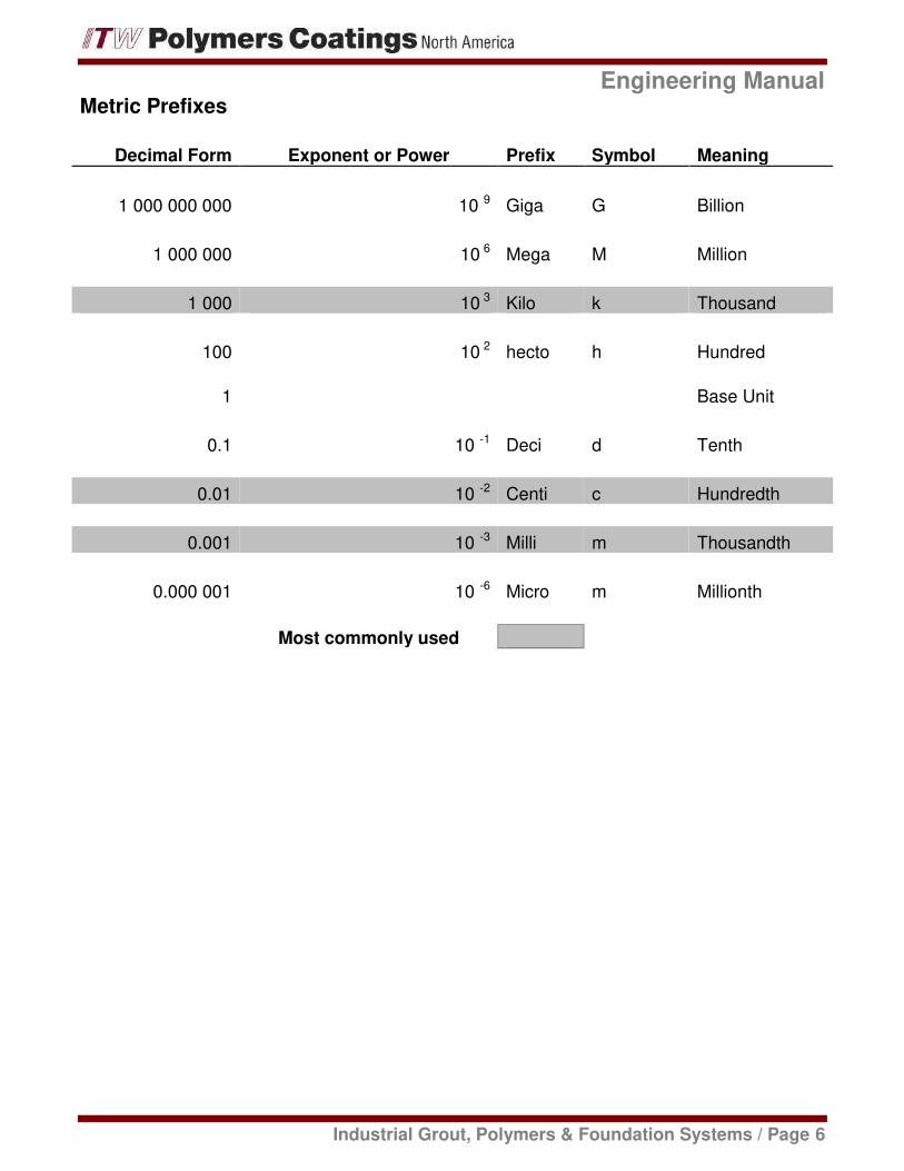
Metric Prefixes
Decimal Form Exponent or Power Prefix Symbol Meaning
1 000 000 000 10 9 Giga G Billion
1 000 000 10 6 Mega M Million
1 000 10 3 Kilo k Thousand
100 10 2 hecto h Hundred
1 Base Unit
0.1 10 -1 Deci d Tenth
0.01 10 -2 Centi c Hundredth
0.001 10 -3 Milli m Thousandth
0.000 001 10 -6 Micro m Millionth
Most commonly used
Engineering Manual
Industrial Grout, Polymers & Foundation Systems / Page 7
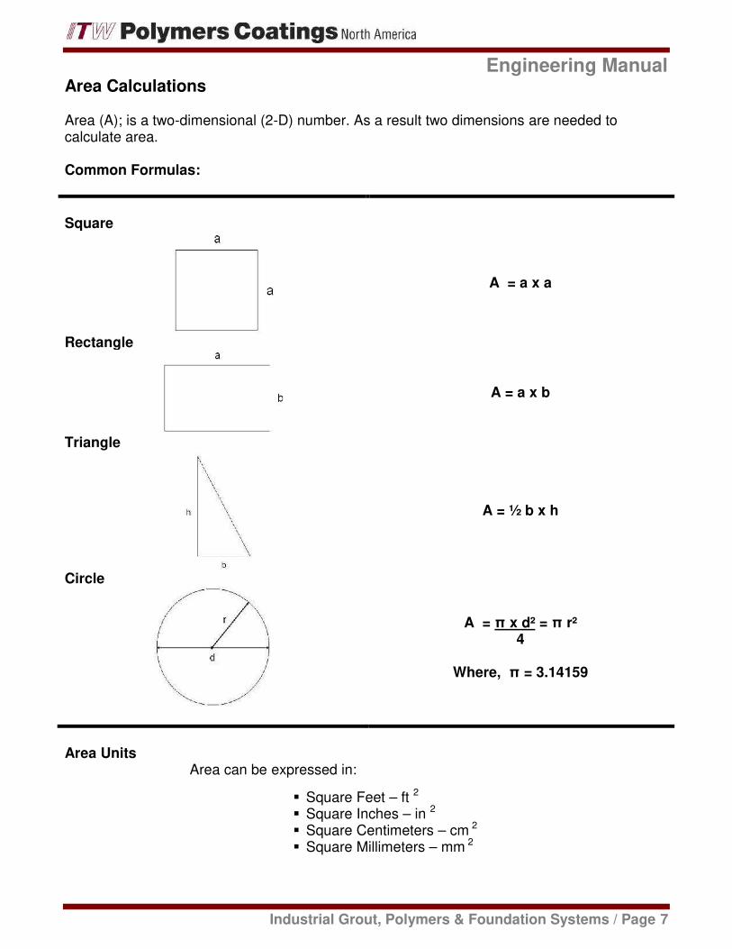
Area Calculations
Area (A); is a two-dimensional (2-D) number. As a result two dimensions are needed tocalculate area.
Common Formulas:
Square
A = a x a
Rectangle
A = a x b
Triangle
A = ½ b x h
Circle
A = π x d² = π r²
4
Where, π = 3.14159
Area Units
Area can be expressed in:
Square Feet – ft 2
Square Inches – in 2
Square Centimeters – cm 2
Square Millimeters – mm 2

Engineering Manual
Industrial Grout, Polymers & Foundation Systems / Page 8
Volume Calculations
Volume (V); is a three-dimensional (3-D) number. It is an area times its height or thicknesswhich means three dimensions are needed.
Common Formulas:
Cube
V = a x a x a
Box
V = a x b x c
Flat Bottomed, Cylindrical Tank
V = π x d² x h4
Where, π = 3.14159
Volume UnitsVolume can be expressed in:
Cubic Feet – ft 3
Cubic Inches – in 3
Cubic Centimeters – cm 3
Cubic Millimeters – mm 3
GallonsLiters

Engineering Manual
Industrial Grout, Polymers & Foundation Systems / Page 9
Example
What volume of coating is needed to cover a floor 100 ft. by 350 ft at a thicknessof 0.005 in (5 mils)?
Solution: The calculation can be done in either ft 3 or in 3.
V = a x b x c, where we let:
a = 100 ftb = 350 ftc = 0.005 in.
Let’s change feet to inches so the answer will be in cubic inches:
V = (100 x 12) x (350 x 12) x 0.005 = 25 200 in 3
This can now be converted to gallons:
V = 25 200 = 109 Gallons231

Engineering Manual
Industrial Grout, Polymers & Foundation Systems / Page 10
Conversions
atmospheres x 1.033 = kg/sq. cm
atmospheres x 1.47 = pounds/sq. in.
bars x 0.9869 = atmospheres
bars x 1.02 = kg/sq. cm.
bars x 14.5 = pounds/sq. in.
centigrade(degrees) (º C x 9/5) + 32 = fahrenheit (degrees)
centimeters x 0.03281 = feet
centimeters x 0.3937 = inches
centimeters x 0.00001 = kilometers
centimeters x 0.01 = meters
centimeters x 10 = millimeters
centimeters x 393.7 = mils
cubic centimeters x 0.00003531 = cubic feet
cubic centimeters x 0.06102 = cubic inches
cubic centimeters x 0.000001 = cubic meters
cubic centimeters x 0.0002642 = gallons
cubic centimeters x 0.001 = liters
cubic feet x 28320 = cubic centimeters
cubic feet x 1728 = cubic inches
cubic feet x 0.02832 = cubic meters
cubic feet x 7.48052 = gallons
cubic feet x 28.32 = liters
cubic inches x 16.39 = cubic centimeters
cubic inches x 0.0005787 = cubic feet
cubic inches x 0.00001639 = cubic meters
cubic inches x 0.004329 = gallons
cubic inches x 0.01639 = liters
cubic meters x 10000 = cubic centimeters
cubic meters x 35.31 = cubic feet
cubic meters x 61023 = cubic inches
cubic meters x 264.2 = gallons
cubic meters x 1000 = liters
fahrenheit (degrees) (º F - 32) x 5/9 = centigrade (degrees)
fathoms x 6 = feet
feet x 30.48 = centimeters
feet x 0.0003048 = kilometers
feet x 0.3048 = meters
feet x 304.8 = millimeters
feet x 12000 = mils
foot-pounds x 0.1383 = kilogram-meters
gallons x 3785 = cubic centimeters
gallons x 0.1337 = cubic feet
gallons x 231 = cubic inches
gallons x 0.003785 = cubic meters
gallons x 3.785 = liters
gallons of water x 8.337 = pounds of water
grams x 0.001 = kilograms
grams x 0.002205 = pounds

Engineering Manual
Industrial Grout, Polymers & Foundation Systems / Page 11
Conversions
inches x 2.54 = centimeters
inches x 0.0254 = meters
inches x 25.4 = millimeters
inches x 0.001 = mils
kilograms x 1000 = grams
kilograms x 2.2 = pounds
kilograms/sq. cm. x 0.9678 = atmospheres
kilograms/sq. cm. x 14.22 = pounds/sq. in.
kilogram-meters x 7.233 = foot-pounds
kilometers x 100000 = centimeters
kilometers x 3281 = feet
kilometers x 39370 = inches
kilometers x 1000 = meters
kilometers x 1000000 = millimeters
kilopascals x 0.145 = pounds/sq. in.
knots x 1.151 = mile/hour
liters x 1000 = cubic centimeter
liters x 0.03531 = cubic feet
liters x 61.02 = cubic inches
liters x 0.001 = cubic meters
liters x 0.2642 = gallons
liters x 1.06 = quarts
megapascals x 145 = pounds/sq. in.
meters x 100 = centimeters
meters x 0.54681 = fathoms
meter x 3.281 = feet
meters x 0.3937 = inches
meters x 0.001 = kilometers
meters x 1000 = millimeters
microns x 0.000001 = meters
milligrams x 0.001 = grams
millimeters x 0.1 = centimeters
millimeters x 0.003281 = feet
millimeters x 0.03937 = inches
millimeters x 0.000001 = kilometers
millimeters x 0.001 = meters
millimeters x 39.37 = mils
mils x 0.00254 = centimeters
mils x 0.0000833 = feet
mils x 0.001 = inches
newtons x 0.2248 = pounds
ounces x 28.349 = grams
ounces x 0.0625 = pounds
pounds x 4.448 = newtons
pounds x 453.6 = grams
pounds x 0.4536 = kilograms
pounds x 16 = ounces
pounds of water x 0.01602 = cubic feet

Engineering Manual
Industrial Grout, Polymers & Foundation Systems / Page 12
Conversions
pounds of water x 27.68 = cubic inches
pounds of water x 0.1198 = gallons
pounds/sq. in. x 0.06804 = atmospheres
pounds/sq. in. x 0.0703 = kg /sq. cm.
pounds/sq. in. x 6.895 = kilopascals
pounds/sq. in. x 0.006895 = megapascals
square centimeters x 0.001076 = square feet
square centimeters x 0.155 = square inches
square centimeters x 0.0001 = square meters
square centimeters x 100 = square millimeters
square feet x 929 = square centimeters
square feet x 144 = square inchessquare feet x 0.0929 = square meters
square feet x 92900 = square millimeters
square inches x 6.452 = square centimeters
square inches x 0.006944 = square feet
square inches x 645.2 = square millimeters
square meters x 10000 = square centimeters
square meters x 10.76 = square feet
square meters x 1550 = square inches
square meters x 1000000 = square millimeters
square millimeters x 0.01 = square centimeters
square millimeters x 0.0000108 = square feet
square millimeters x 0.00155 = square inches
tons (metric) x 1000 = kilograms
tons (metric) x 2205 = pounds
tons x 2000 = pounds
Industrial Grouts, Polymers & Foundation Systems
Secti
on
3/
En
gin
eeri
ng

This Page Left Intentionally Blank

Engineering Manual
Industrial Grout, Polymers & Foundation Systems / Page 13
Section 3 / EngineeringEngineering
The science concerned with putting scientific knowledge to practical use.
Force
A push or pull on a body. There are different types of forces:
WeightGravityMagneticElectrical
Force is represented by an arrow showing magnitude and direction (also called a vectorquantity).
If we want to indicate a table which has a book on it is subjected to the weight of the book wecan represent it as such:
Engineering Manual
Industrial Grout, Polymers & Foundation Systems / Page 14
Stress
Stress is the effect of an external force applied upon a solid material. The solid material has aninternal resistance that absorbs the external force. This internal resistance is expressed inpounds per square inch (lb/in 2 or psi).
The level of stress in a solid depends upon the amount of force and the surface on which theforce acts. There are several types of stress:
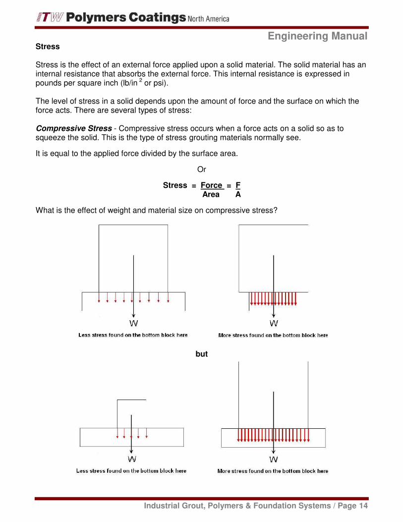
Compressive Stress - Compressive stress occurs when a force acts on a solid so as tosqueeze the solid. This is the type of stress grouting materials normally see.
It is equal to the applied force divided by the surface area.
Or
Stress = Force = FArea A
What is the effect of weight and material size on compressive stress?
but

Engineering Manual
Industrial Grout, Polymers & Foundation Systems / Page 15
Note that force by itself will not give a true picture of an application in regard to its strength. Bysaying a foundation has a load of 20 tons on it does not imply weather the structure is strongenough or not. It is necessary to know the area on which the force is acting.
Example:
A load of 16,000 lb is placed on a CHOCKFAST Orange chock that is 12 inches long and8 inches deep. What is the compressive stress on the chock?
Stress = FA
Where: F = 16,000 lbA = 12 in x 8 in = 96 in 2
Stress = 16,000 = 166.6 psi96
Example:
Suppose the chock is reduced in size to only 9 inches long. What is the new stress level?
Stress = FA
Where: F = 16,000 lbA = 9 in x 8 in = 72 in 2
Stress = 16,000 = 222.2 psi72

Engineering Manual
Industrial Grout, Polymers & Foundation Systems / Page 16
Tensile Stress - Tensile stress occurs when a force acts on a solid so as to stretch the solid
Stress = Force = F = FArea A a x b
Shear Stress - Shear or Shearing Stress occurs when a force causes one side of a solid to“slide” in relation to the other side.
Engineering Manual
Industrial Grout, Polymers & Foundation Systems / Page 17
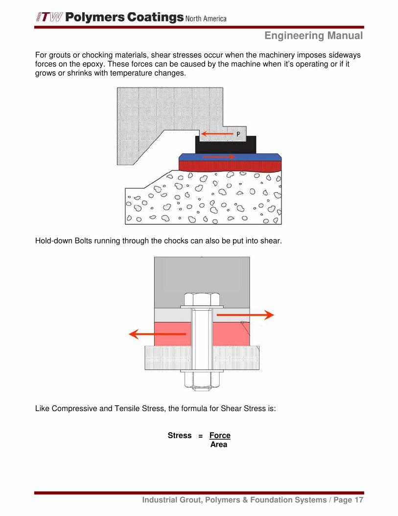
For grouts or chocking materials, shear stresses occur when the machinery imposes sidewaysforces on the epoxy. These forces can be caused by the machine when it’s operating or if itgrows or shrinks with temperature changes.
Hold-down Bolts running through the chocks can also be put into shear.
Like Compressive and Tensile Stress, the formula for Shear Stress is:
Stress = ForceArea

Engineering Manual
Industrial Grout, Polymers & Foundation Systems / Page 18
Example:
What is the shear stress on a 1 in. diameter bolt subjected to a shear force of 8,000 lbs.?
Stress = FA
Where: F = 8,000 lbA = π x (1 in) 2 /4 = 3.1415 /4 = 0.785 in 2 (Area of a Circle)
Stress = 8,000 = 10,191 psi0.785
Note that a shearing stress placed on a cross-sectional area of a solid is parallel to thesurface, not perpendicular, as in the case of compressive or tensile stress.

Engineering Manual
Industrial Grout, Polymers & Foundation Systems / Page 19
Strain
Strain is the deformation per unit length of a solid under stress.
Deformation is a change in dimension. In Engineering a change is a difference or delta. Deltais a Greek letter represented as, ΔFor example a change in length is delta L or, Δ L
Therefore:
Strain = Δ L or Change in LengthL Original Length
Example:
Due to a tensile stress placed on it, a 25 in. long metal rod assumes a length of 25.025 inches.What is the strain on the rod?
Strain = Δ L or Change in LengthL Original Length
Where:
Δ L = 25.025 - 25.0 = 0.025 in. and L = 25 in.
Strain = 0.025 in = 0.00125.0 in

Engineering Manual
Industrial Grout, Polymers & Foundation Systems / Page 20
Modulus of Elasticity
The relationship between stress and strain is a term called the modulus.
The modulus of elasticity of a material is an index of its elasticity or the ability of a solidmaterial to deform when an external force is applied to it, then return to its original shape afterthe removal of the external force. For a certain level of stress placed on a material there will bea certain amount of strain depending upon the modulus of elasticity.
The modulus of elasticity of a material is represented by E for Tension and Compression andES for Shear. The units are lb/in 2.
MaterialModulus of Elasticity in PSI
Tension & Compression Shear
Steel 30,000,000 12,000,000
Copper 13,000,000 6,000,000
Aluminum 10,000,000 4,000,000
Concrete 3,000,000 - 6,000,000 -
PVC 300,000 -
CHOCKFAST Orange 533,000 100,000
CHOCKFAST Gray 520,000 -
If we know the modulus of elasticity of a material we can calculate how much it will deflect for agiven load. Another way to say this is for a given material we can calculate the strain if weknow the stress.
The relationship between stress and strain is:
Stress = E x Strain or E = Stress or Strain = StressStrain E
Example:
A CHOCKFAST Orange chock will have a load of 25,000 lbs placed on it. The chock is 18inches long and 16 inches deep. The thickness before it is loaded is 1-¼ inches. How muchwill the chock deflect due to the load?
Engineering Manual
Industrial Grout, Polymers & Foundation Systems / Page 21
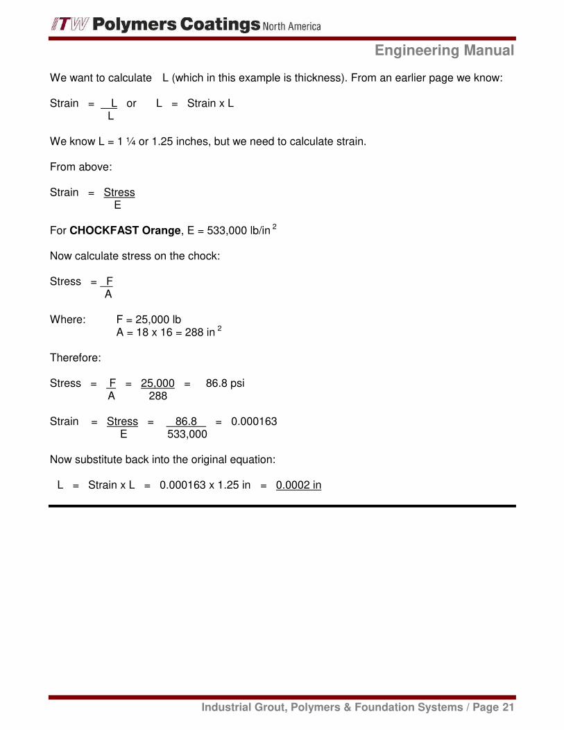
We want to calculate Δ L (which in this example is thickness). From an earlier page we know:
Strain = Δ L or Δ L = Strain x LL
We know L = 1 ¼ or 1.25 inches, but we need to calculate strain.
From above:
Strain = StressE
For CHOCKFAST Orange, E = 533,000 lb/in 2
Now calculate stress on the chock:
Stress = FA
Where: F = 25,000 lbA = 18 x 16 = 288 in 2
Therefore:
Stress = F = 25,000 = 86.8 psiA 288
Strain = Stress = 86.8 = 0.000163E 533,000
Now substitute back into the original equation:
Δ L = Strain x L = 0.000163 x 1.25 in = 0.0002 in
Engineering Manual
Industrial Grout, Polymers & Foundation Systems / Page 22
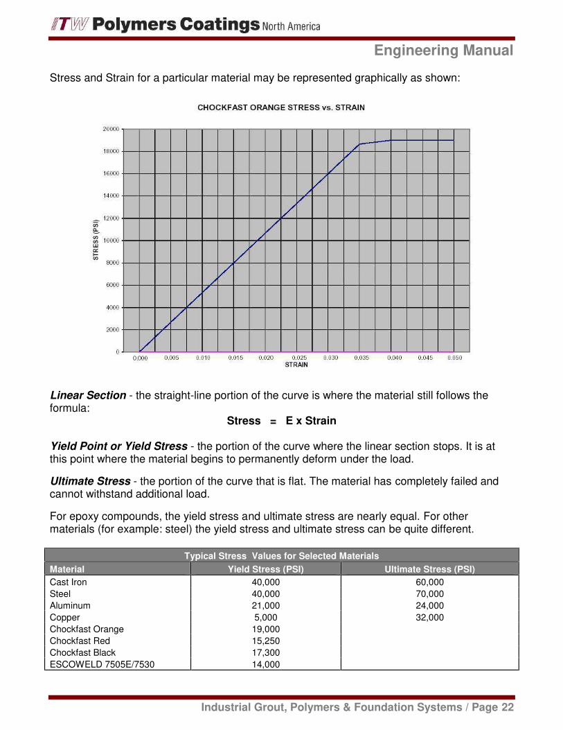
Stress and Strain for a particular material may be represented graphically as shown:
Linear Section - the straight-line portion of the curve is where the material still follows theformula:
Stress = E x Strain
Yield Point or Yield Stress - the portion of the curve where the linear section stops. It is atthis point where the material begins to permanently deform under the load.
Ultimate Stress - the portion of the curve that is flat. The material has completely failed andcannot withstand additional load.
For epoxy compounds, the yield stress and ultimate stress are nearly equal. For othermaterials (for example: steel) the yield stress and ultimate stress can be quite different.
Typical Stress Values for Selected Materials
Material Yield Stress (PSI) Ultimate Stress (PSI)
Cast Iron 40,000 60,000
Steel 40,000 70,000
Aluminum 21,000 24,000
Copper 5,000 32,000
Chockfast Orange 19,000
Chockfast Red 15,250
Chockfast Black 17,300
ESCOWELD 7505E/7530 14,000
Indus
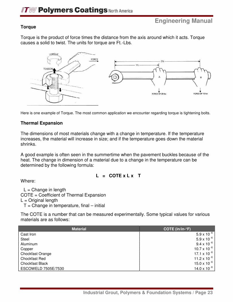
Torque
Torque is the product of force timecauses a solid to twist. The units f
Here is one example of Torque. The mos
Thermal Expansion
The dimensions of most materials increases, the material will increaseshrinks.
A good example is often seen in theat. The change in dimension ofdetermined by the following formu
Where:
Δ L = Change in lengthCOTE = Coefficient of Thermal ExL = Original lengthΔ T = Change in temperature, fina
The COTE is a number that can bmaterials are as follows:
Material
Cast Iron
Steel
Aluminum
Copper
Chockfast Orange
Chockfast Red
Chockfast Black
ESCOWELD 7505E/7530
Enginee
Industrial Grout, Polymers & Foundation S
imes the distance from the axis around which ts for torque are Ft.-Lbs.
ost common application we encounter regarding torqu
als change with a change in temperature. If thease in size; and if the temperature goes dow
n the summertime when the pavement buckle of a material due to a change in the temperatmula:
Δ L = COTE x L x Δ T
Expansion
nal – initial
n be measured experimentally. Some typical v
ial COTE
ngineering Manual
on Systems / Page 23
ch it acts. Torque
torque is tightening bolts.
the temperaturewn the material
ckles because of therature can be
l values for various
E (in/in-°F)
5.9 x 10⁻⁶
5.9 x 10⁻⁶
9.4 x 10⁻⁶
10.7 x 10⁻⁶
17.1 x 10⁻⁶
11.2 x 10⁻⁶
15.0 x 10⁻⁶
14.0 x 10⁻⁶

Engineering Manual
Industrial Grout, Polymers & Foundation Systems / Page 24
Notice if the change in temperature (final temperature - initial temperature) is positive, thechange in length is positive. If the change is negative (meaning the material is cooling) thelength change is negative.
Example:
A CHOCKFAST Black chock 1-¼ inches high cools from 125 º F down to 70 º F. What will bethe change in height?
Δ L = COTE x L x Δ TFor CHOCKFAST Black:
COTE = 15 x 10-6 in/in - º FL = 1.25 in.
Δ T = 70 - 125 = -55 º F
Δ L = 15 x 10 -6 x 1.25 x -55 = - 0.001 in.
Some Additional Engineering Concepts
Creep - The gradual and permanent deformation of a material that is subjected to a stress lessthan yield stress. This phenomenon usually occurs over periods of years.
A good example is the springs in your car. We generally say they are “worn out” when the carstarts to bottom out on bumps even though it is not fully loaded.
It is usually because of creep considerations that epoxies are loaded far below their yieldpoints.
Friction - That force which opposes the motion of one material across another.
The formula for friction is: Ff = µN
Engineering Manual
Industrial Grout, Polymers & Foundation Systems / Page 25
Where:
Ff = Friction ForceP = Pulling (or Pushing) ForceN = Normal Force (weight)
µ = (Mu) Coefficient of Friction
The coefficient of friction is an experimental number and is dependent upon both surfaces. Thecoefficient of friction of CHOCKFAST Orange on steel is different from the coefficient offriction of CHOCKFAST Orange on wood.
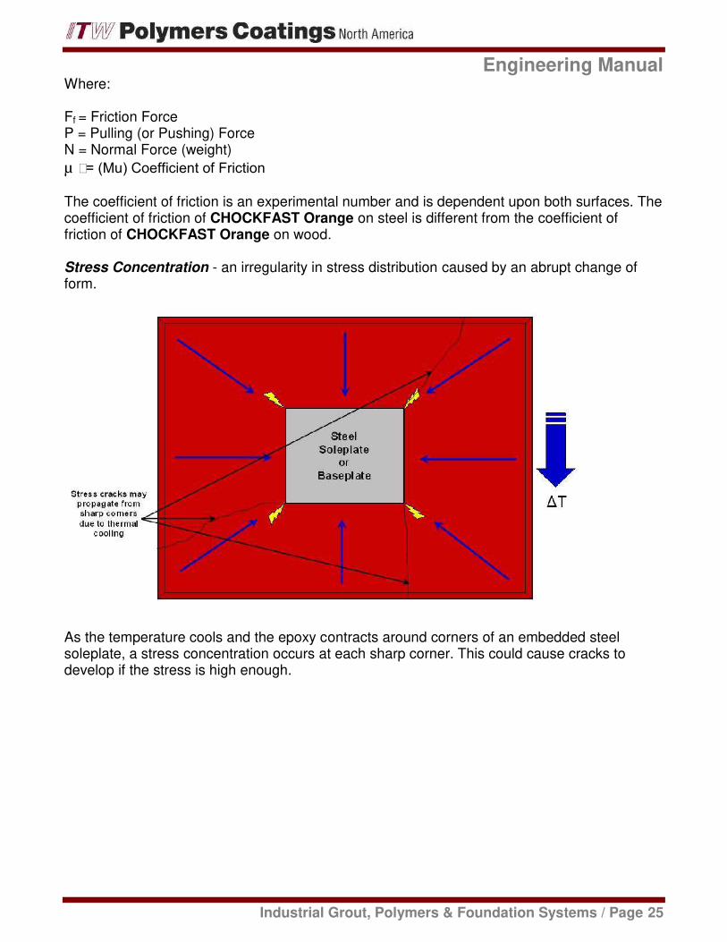
Stress Concentration - an irregularity in stress distribution caused by an abrupt change ofform.
As the temperature cools and the epoxy contracts around corners of an embedded steelsoleplate, a stress concentration occurs at each sharp corner. This could cause cracks todevelop if the stress is high enough.

This Page Left Intentionally Blank

Industrial Grouts, Polymers & Foundation Systems
Secti
on
4/
Ap
pli
cati
on
s

This Page Left Intentionally Blank
Engineering Manual
Industrial Grout, Polymers & Foundation Systems / Page 26
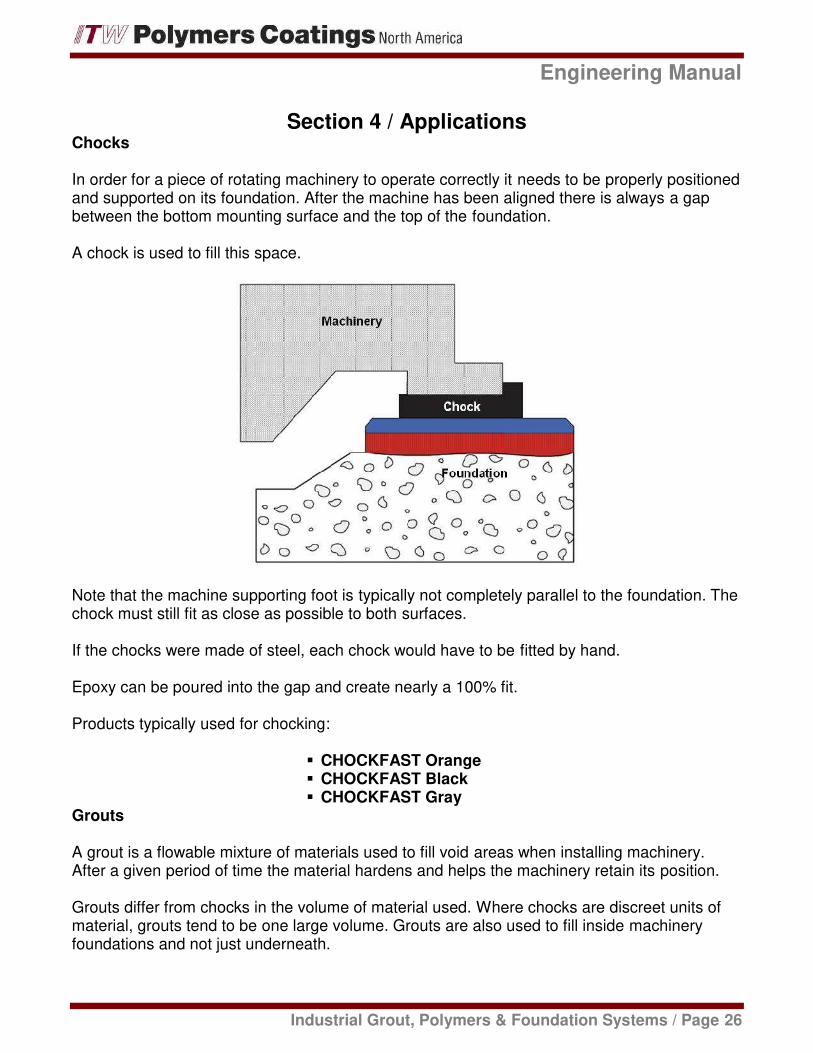
Section 4 / ApplicationsChocks
In order for a piece of rotating machinery to operate correctly it needs to be properly positionedand supported on its foundation. After the machine has been aligned there is always a gapbetween the bottom mounting surface and the top of the foundation.
A chock is used to fill this space.
Note that the machine supporting foot is typically not completely parallel to the foundation. Thechock must still fit as close as possible to both surfaces.
If the chocks were made of steel, each chock would have to be fitted by hand.
Epoxy can be poured into the gap and create nearly a 100% fit.
Products typically used for chocking:
CHOCKFAST OrangeCHOCKFAST BlackCHOCKFAST Gray
Grouts
A grout is a flowable mixture of materials used to fill void areas when installing machinery.After a given period of time the material hardens and helps the machinery retain its position.
Grouts differ from chocks in the volume of material used. Where chocks are discreet units ofmaterial, grouts tend to be one large volume. Grouts are also used to fill inside machineryfoundations and not just underneath.

Engineering Manual
Industrial Grout, Polymers & Foundation Systems / Page 27
In the case of a machinery base plate, oftentimes the complete inside is filled with grout whenthe equipment is installed.
The grout provides complete contact for the base plate to the foundation itself.
When machinery is installed on sole plates, the soleplates are grouted into the concretefoundation, and then the machinery is chocked to the soleplate.
In many cases the grout application can be very deep. Most grouts get too hot when they cureand therefore contract too much when they cool, causing cracks and poor bonds. The solutionfor these grouts is to pour in layers.
Epoxy Grout products typically used for grouting:
CHOCKFAST Red – Large volume, single pours of 2" to 18” (51 mm to 457 mm).ESCOWELD® 7505/7530 - Large volume, single pours of 2" to 18” (51 mm to 457 mm).CWC 604 Machine Bond - Large volume, single pours of 2" to 18” (51 mm to 457 mm).CHOCKFAST Red HF - Large volume, single pours of 1" to 4" (25 mm to 102 mm)CHOCKFAST Red SG – Medium to small volume; single pours of 1” to 3 “(25 mm to 76 mm)CHOCKFAST Blue – Smaller volume pours of 1” to 1 ½” (25 mm to 38 mm).
Engineering Manual
Industrial Grout, Polymers & Foundation Systems / Page 28
Control Joints
Epoxy grouts develop heat during the curing process (Also refer to “Curing” under Section 6).During this time, they will typically phase from a plastic, workable material to an eventual solidmaterial as the chemical reaction taking place enables the grout develop its structural strength& integrity. This is considered the “gel” time; and it is also the point where the maximumtemperature is attained. The maximum temperature reached is dependent on a number ofvariables:
Amount or mass of epoxy grout used, (l x w x d)Temperatures:
o Epoxy grout components at the time of mixingo Ambient airo Adjacent surfaces that come in contact with the curing grout
All of these variables can affect the temperature and rate of cure of an epoxy grout. The higherthe temperature value for one or more of these variables; the higher the maximum exothermictemperature becomes as well.
After the gel point is reached and the epoxy grout becomes a solid material, the temperaturegoes down. As the temperature decreases, the epoxy grout will contract. As the materialcracks, increasing stresses develop and are locked into the epoxy grout until its physical limitsare reached. This concludes in the form of a thermal stress crack.
The differential between initial peak exothermic temperature during installation and lowerpotential temperatures that may be experienced in the environment later; will influence theprobability and frequency of crack development.
Cracks can develop as soon as the epoxy grout cools down after the initial exothermicepisode. They can also occur weeks, months and even years after installation if ambientconditions in the immediate area drop far enough to continue building stresses to where thephysical limits of the cured grout are overcome.
This is a known occurrence and is common in many materials that react chemically andundergo a heat-related cure. Concrete is a most common example. Thermal cracks can andwill occur, but they can be anticipated and planned for through the considerate and intentionalplacement of prefabricated control joints (sometimes more commonly referred to as expansionjoints) in the epoxy grout. Control joints can also be thought of as an “engineered crack”.
Joint placement and frequency may be determined with careful consideration to the followingvariables:
Initial cure environment of the epoxy grout
Equipment type and configuration
Operating temperatures of the equipment and its environment.
Magnitude and frequency of possible thermal changes that may occur within theoperating environment.
Coefficient of Thermal Expansion of the Epoxy Grout.

Engineering Manual
Industrial Grout, Polymers & Foundation Systems / Page 29
Also, the thermal coefficients of epoxy grout, concrete and steel can contribute to the potentialfor grout cracking due to the differential in expansion and contraction rates of each. However,strategically control joints can help to reduce this possibility as well. Joints may be constructedas shown:
Products typically used for sealing control & expansion joints:
ITW PRC Expansion Joint Compound
Vertical thermal cracks do not affect the structural integrity and the ability of the epoxy grout tocounter imposed static and dynamic loads. The major shortcoming of a crack is it becomes adirect path for oils, water and other chemicals to reach, attack and weaken the porousconcrete substrate.
Repairs
Foundation Repairs:
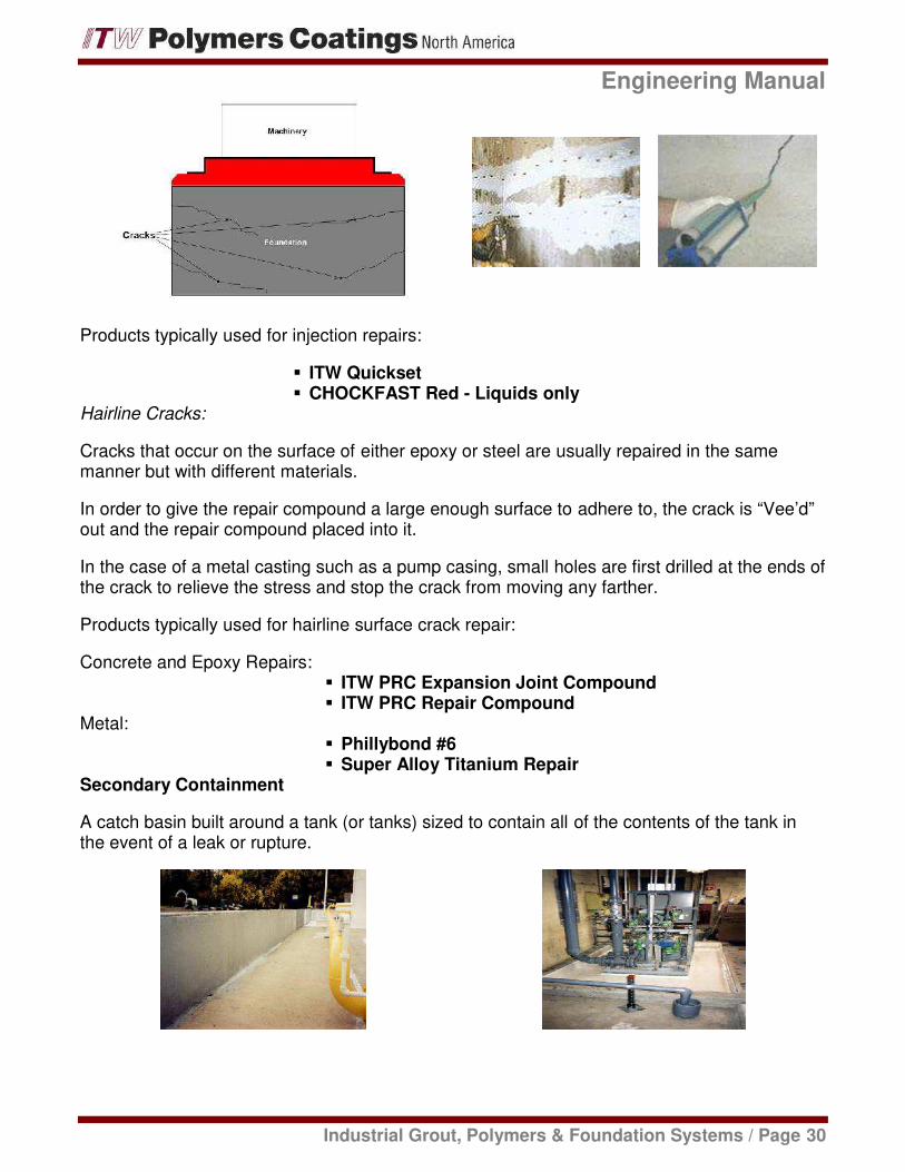
All concrete foundations have cracks particularly in large pours where the amount of concreteshrinkage is significant. These cracks are not serious except from an esthetic point of view.However, cracks that occur because of equipment vibration must be repaired. If not the crackwill continue to grow until the foundation becomes structurally inadequate. Injecting epoxy intothe cracks is a proven repair method. There are many ways to inject epoxy. Here, injectionports have been placed to be used as injection points.
Engineering Manual
Industrial Grout, Polymers & Foundation Systems / Page 30
Products typically used for injection repairs:
ITW QuicksetCHOCKFAST Red - Liquids only
Hairline Cracks:
Cracks that occur on the surface of either epoxy or steel are usually repaired in the samemanner but with different materials.
In order to give the repair compound a large enough surface to adhere to, the crack is “Vee’d”out and the repair compound placed into it.
In the case of a metal casting such as a pump casing, small holes are first drilled at the ends ofthe crack to relieve the stress and stop the crack from moving any farther.
Products typically used for hairline surface crack repair:
Concrete and Epoxy Repairs:ITW PRC Expansion Joint CompoundITW PRC Repair Compound
Metal:Phillybond #6Super Alloy Titanium Repair
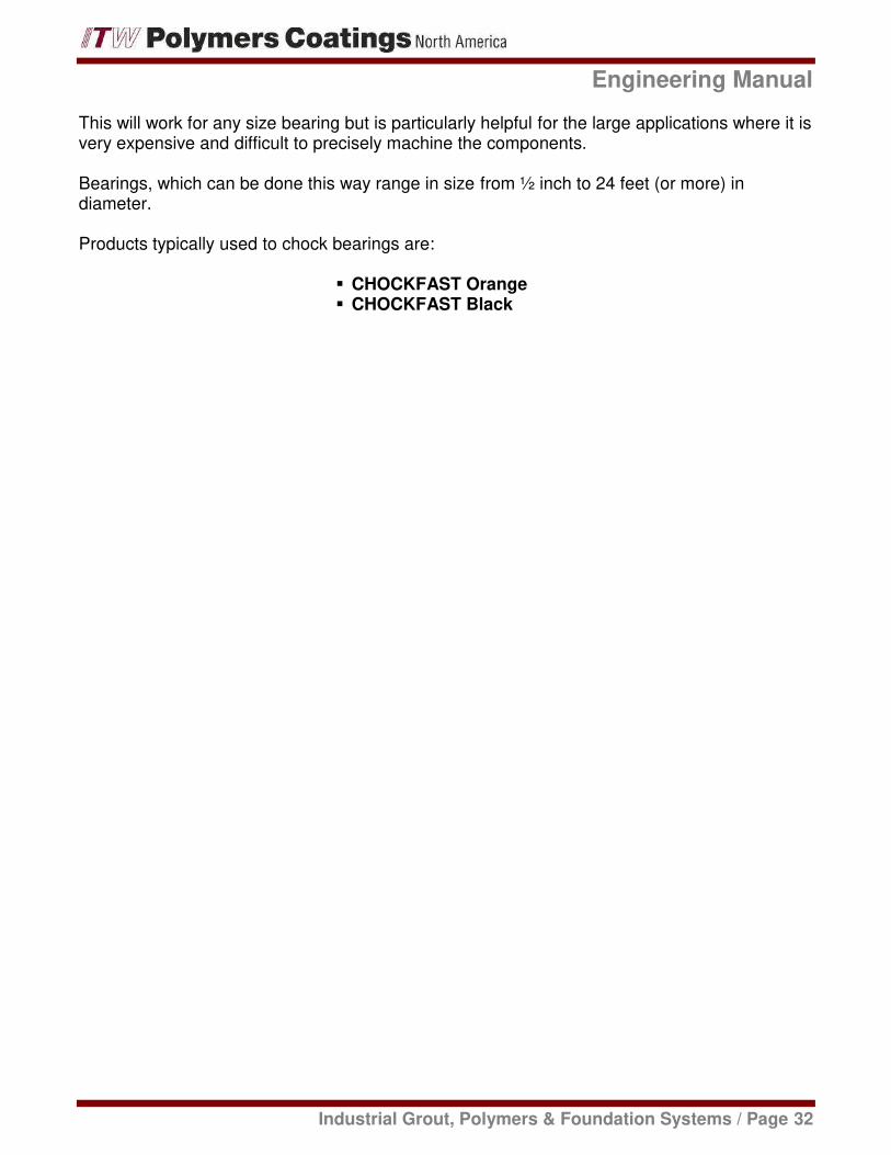
Secondary Containment
A catch basin built around a tank (or tanks) sized to contain all of the contents of the tank inthe event of a leak or rupture.

Indus
The secondary containment systeof time of 24 hours even if the ma
Products typically used for second
PolySpec NovoRePolySpecTuff Rez
Fairing Materials
Fairing is a marine term that meanshape of a surface can create turb
A fairing material is basically a filli
Products typically used for a fairin
ITWBearings
Bearings are usually held in placethe structure that holds it.
The problem arises when the beamade for it.
The answer is to make the bore labe, and fill the gap with epoxy.
Enginee
Industrial Grout, Polymers & Foundation S
stem must be able to contain the contents for aterials are corrosive.
ndary containment coating systems:
Rez 351 - High Solids Novolac EpoxyRez 200CR - Acid Resistant Epoxy Floor Resur
eans to make smooth or streamlined. An abruurbulence as it moves through the water causi
filling material.
iring material:
TW PRC Repair Compound
ce by an interference fit – the bearing is a little
earing needs to be located off-center from the
larger than necessary, position the bearing w
ngineering Manual
on Systems / Page 31
or a minimum period
surfacer
rupt change inusing erosion.
ittle bit bigger than
the bore that was
g where it needs to
Engineering Manual
Industrial Grout, Polymers & Foundation Systems / Page 32
This will work for any size bearing but is particularly helpful for the large applications where it isvery expensive and difficult to precisely machine the components.
Bearings, which can be done this way range in size from ½ inch to 24 feet (or more) indiameter.
Products typically used to chock bearings are:
CHOCKFAST OrangeCHOCKFAST Black

This Page Left Intentionally Blank

Industrial Grouts, Polymers & Foundation Systems
Secti
on
5/
Testi
ng

This Page Left Intentionally Blank

Engineering Manual
Industrial Grout, Polymers & Foundation Systems / Page 33
Section 5 / Testing
ASTM - American Society for Testing and Materials.
The headquarters is in Conshohocken, PA.
Organized in 1898
Voluntary standards development organization
Not-for-Profit
134 standards-writing committees, 8,500 standards, organized by discipline.
Has no technical or testing facility. All work is done voluntarily by 33,000 ASTMmembers located throughout the world
Philosophy behind ASTM Testing
Some tests produce results of a practical nature that can be used as actual design criteria:
Compressive TestsTensile TestsCoefficient of Thermal Expansion
Some tests produce results of a comparative nature. The results cannot be used for actualdesign, but can be helpful to compare different materials to each other:
Shrink on cureGel TimeCreep
Commonly Used Tests
Compressive Tests
These tests require a 2-inch cube for a test specimen. The cube is then loaded by a testmachine (e.g. Tinius Olsen) until it breaks.

Engineering Manual
Industrial Grout, Polymers & Foundation Systems / Page 34
Typical ASTM test methods used:
ASTM C 579 - Chemical Resistant Mortars, Grouts, Polymer ConcreteASTM D 695 - Rigid Plastics
Tensile Tests
These tests require specimens be prepared according to specific dimensions. They are placedin a test machine and pulled until they break.
Typical ASTM test methods used:
ASTM C 307 - Chemical Resistant Mortars, Grouts, Polymer Concrete
“Dog Bone” Type Specimen
ASTM D 638 – Plastics
Rod Type Specimen

Engineering Manual
Industrial Grout, Polymers & Foundation Systems / Page 35
Shrinkage and Linear Coefficient of Thermal Expansion
Typical ASTM test methods used:
ASTM C 531 - Shrinkage and Linear Coefficient of Thermal Expansion
For shrinkage this test requires a test specimen be poured to an exact length. After cure, thelength is measured. The difference between the lengths before and after is the shrinkage. Thistest is best used for comparative purposes.
For the Coefficient of Thermal Expansion the bar is heated to a specified temperature and thelength is measured. The change in length for the specified change in temperature results in thecoefficient. The results from this test can be used in actual applications.
L2 – L1 = Δ L
ASTM D 696 - Coefficient of Linear Thermal Expansion
This test determines the change in length of a specimen due to a change in temperaturewithout removing the specimen from the elevated temperature environment. The specimen isplaced into an environmental chamber and an extension rod, called a dilatometer, is placed soit sits on top of the specimen. The dilatometer extends outside the chamber and a dial indicatorshows the change in length.

Engineering Manual
Industrial Grout, Polymers & Foundation Systems / Page 36
Gel Time and Peak Exothermic Temperature
This test determines the time from initial mixing of the material components to the time whensolidification commences. It also provides a means for measuring the maximum temperaturereached during the reaction. This temperature is best used for comparison purposes.
Creep
Typical ASTM test methods used:
ASTM C 1181 - Compressive Creep
This test is only a comparative test which determines the creep of a material for a given stresslevel and temperature. A specimen in the shape of a doughnut is cast and constant load ismaintained using a torqued bolt and spring washers. The change in height of the specimen ismeasured over a time period of 28 days.
ASTM D 648 - Deflection Temperature
This test is a means to determine the temperature at which a material begins to lose itsstrength properties. The size of the specimen is 5” long x ½” high x ½” wide. It is placed onsupports 4” apart in a temperature-controlled bath. A load is applied to the middle of the bar asthe temperature of the bath is slowly increased. The temperature of the bath when the bar hasdeflected 0.010” is the deflection temperature.

Engineering Manual
Industrial Grout, Polymers & Foundation Systems / Page 37
Curing of Test Samples
It is essential that test specimens be completely cured before performing any tests for physicalproperties otherwise the results will be misleading.
The problem is test specimens that have been cast in molds, normally do not develop a highenough exothermic heat needed for complete cure with a 24-hour period (or longer).
Small test specimens should always be placed in an oven and heated to 170 º F for four hours.After complete cooling, the test may be performed.

This Page Left Intentionally Blank

Industrial Grouts, Polymers & Foundation Systems
Secti
on
6/
Ch
em
istr
y

This Page Left Intentionally Blank
Engineering Manual
Industrial Grout, Polymers & Foundation Systems / Page 38
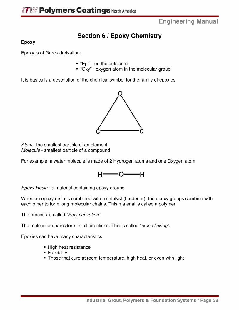
Section 6 / Epoxy ChemistryEpoxy
Epoxy is of Greek derivation:
“Epi” - on the outside of“Oxy” - oxygen atom in the molecular group
It is basically a description of the chemical symbol for the family of epoxies.
Atom - the smallest particle of an elementMolecule - smallest particle of a compound
For example: a water molecule is made of 2 Hydrogen atoms and one Oxygen atom
Epoxy Resin - a material containing epoxy groups
When an epoxy resin is combined with a catalyst (hardener), the epoxy groups combine witheach other to form long molecular chains. This material is called a polymer.
The process is called “Polymerization”.
The molecular chains form in all directions. This is called “cross-linking”.
Epoxies can have many characteristics:
High heat resistanceFlexibilityThose that cure at room temperature, high heat, or even with light

Engineering Manual
Industrial Grout, Polymers & Foundation Systems / Page 39
Curing
The epoxy groups are like chemical springs storing energy. The hardener releases the springcausing the chain reaction that forms the long molecular chains.
The release of energy is in the form of heat. A reaction that releases heat is called“exothermic”.
The practical amount of heat that is experienced as the temperature rises depends uponseveral things:
The amount (mass) of epoxyThe ambient (surrounding) temperatureThe ability of the surrounding surfaces to absorb the heat ( heat sink)
Mass - the larger the mass of epoxy there is; the higher the maximum exothermic temperature.As the polymerization process continues and heat is released, the epoxy begins to turn from aliquid to a solid. This is the gel point. It is also the point at which the maximum temperature isreached.
After the gel point is reached, the temperature goes down. Complete curing is accomplishedby ambient heat, or if it is too low, by externally applied heat.
A high exothermic cure temperature can both help and hurt an epoxy grout installation. Thehigher the exothermic cure temperature, the faster the epoxy grout will cure. Also, the higherthe exothermic cure temperature, the more the epoxy grout will contract and shrink as it coolsto ambient temperature.

Engineering Manual
Industrial Grout, Polymers & Foundation Systems / Page 40
Application Techniques
Because of the nature in which epoxy cures, there are some application techniques whichminimize the effects of shrinkage.
Chocking materials
Because curing is dependent upon the mass, an epoxy chock will begin curing from the center(where the mass is concentrated) out. This is why we use an “Over-pour” or liquid reservoirwhen pouring the chocking materials.
Because it is the last to cure, the over-pour will act as a reservoir from which the chock canpull additional epoxy.
Grouts
Some epoxy grouts (CHOCKFAST Red, for example) have very low exothermic curetemperatures and as a result, do not contract or shrink as much as the temperature returns toambient. However, for any large volume pours that go deeper than 4 inches under criticalalignment conditions; it is a good rule of thumb to perform an initial pour that fills all but the last4 inches from the equipment base. The final 4 inches is poured when the initial pour hascooled.) This is because the deepness of pour and large volume of grout used createsincreased mass. This can cause excess heat buildup even in grouts that typically exhibit lowerexothermic cure temperatures.

This Page Left Intentionally Blank

This Page Left Intentionally Blank

130 Commerce DriveMontgomeryville, PA 18936P 215.855.8450 / F 215.855.4688