Cobra® Snow Country Advanced™ - Technical Notes - BuildSite
298
FOR STEEP-SLOPE ROOFS VERSION 1.0 Pro Field Guide
-
Upload
khangminh22 -
Category
Documents
-
view
0 -
download
0
Transcript of Cobra® Snow Country Advanced™ - Technical Notes - BuildSite

FOR STEEP-SLOPE ROOFS
VERSION 1.0
Pro FieldGuide

Version 1.0
FIELD GUIDE
PRO
FOR STEEP-SLOPE ROOFS

SECTION 1: PROFESSIONAL ROOFINGIntroduction ...................................................................... 4-8 Certification Requirements, Using This WorkbookCustomer Management.................................................. 9-10 Customer Management, Complete Customer SatisfactionRoofing Safety............................................................... 11-16 Safety Common Sense, Ladders, Tools, Handling
Emergencies Roofing Safety (Review #1) .............................................. 17SECTION 2: ROOFING BASICSShingle Manufacturing ................................................. 18-20 Shingle Components, The GAF Difference Shingle Manufacturing (Review #2) ................................. 21General Roofing Knowledge......................................... 22-24 Roof Types, Common Roofing Terms, Roof Slope and PitchTearing Off Old Roofing ................................................ 25-28 Tear Off Or Install Two Roof Layers, Tearing Off Roof Good
Practices Tearing Off Old Roofing (Review #3) ................................ 29Dealing with Decks ....................................................... 30-38 Roof Deck Basics, Installing Plywood, Insulation and Other Decks, ThermaCal® Nail Base Roof Insulation Panels, ThermaCal® Fasteners, Installation
Dealing with Decks (Review #4) ....................................... 39Installing Complete Roofing Systems .......................... 40-41 GAF Lifetime Roofing System, Installing Metal Drip Edge Installing Complete Roofing Systems (Review #5) ........... 42SECTION 3: INSTALLING SYSTEM ACCESSORIESInstalling Leak Barriers ................................................. 43-62 WeatherWatch® and StormGuard®, Critical Leak Areas, Leak Barrier Locations, Sealing at Plumbing Vents, Sealing Off Dormers and Side Walls, Sealing Shingle-to-Shingle Transition Areas, Sealing Skylights
Installing Leak Barriers (Review #6) ................................. 63Installing Roof Deck Protection ................................... 64-79 Shingle-Mate®, Tiger Paw™, and Deck-Armor™
Installing Roof Deck Protection (Review #7) .................... 80Ventilation Needs ......................................................... 81-84 Attic Moisture, Heat, and Ice Dams Ventilation Needs (Review #8) ......................................... 85Ventilation Solutions .................................................. 86-135 Guide lines, FHA, Soffits, Cathedral Ceilings, Hip Roofs,
Cobra® Attic Vents, One-Sided Gable Roofs, Power Vents Ventilation Solutions (Review #9) .................................. 136SECTION 4: INSTALLING GAF SHINGLESGeneral Fastening and Wind Resistance ................. 137-149 Pre-Shingling Checklist, Hand-Sealing Shingles, Steep-
Slope Precautions, Starter Strips General Fastening & Wind Resistance (Review #10) ..... 150Sovereign™ Series Shingles ....................................... 151-159 About Sovereign™ Series, Installation, Hip and Ridge Sovereign™ Series Shingles (Review #11) ....................... 160Timberline® Series Shingles ...................................... 161-168 About Timberline® Series, Installation Timberline® Series Shingles (Review #12) ...................... 169
STEEP-SLOPE PRO FIELD GUIDE WORKBOOK CONTENTS
22222222222222222222

Grand Sequoia®/Grand Canyon® Shingles .............170-176 About Grand Sequoia®/Grand Canyon® Shingles, Installation
Grand Sequoia®/Grand Canyon® Shingles (Review #13) ................................................................ 177
Woodland® Shingles ...............................................178-183 About Woodland® Shingles, Installation Woodland® Shingles (Review #14) .............................. 184Sienna® Shingles .....................................................185-189 About Sienna® Shingles, Installation Sienna® Shingles (Review #15) .................................... 190Slateline® Shingles ..................................................191-195 About Slateline® Shingles, Installation Slateline® Shingles (Review #16) ................................. 196Camelot® Shingles ..................................................197-200 About Camelot® Shingles, Installation Camelot® Shingles (Review #17) ................................... 201 Glenwood® Shingles ...............................................203-208 About Glenwood® Shingles, Installation Glenwood® Shingles (Review #18) ............................... 209 SECTION 5: INSTALLING FLASHING SYSTEMSInstalling Enhanced Capping ................................210-220 Timbertex®, Z®Ridge, Seal-A-Ridge®, Ridglass®
Installing Enhanced Capping (Review #19) ................. 221Installing Shingle Valleys ......................................222-230 Open, Closed Cut, Woven, Open California, Closed Cut CaliforniaInstalling Wall Flashing Systems ...........................231-241 Step Flashing, Horizontal Walls Installing Wall Flashing (Review #20) .......................... 242Installing Chimney Flashing Systems ....................243-257 Crickets, Underlayments, Aprons, Step Flashing, Counter Flashing, Backer Flashing Installing Chimney Flashing Systems (Review #21) ..... 258Flashing Roof Projections ......................................259-263 Skylights, Plumbing Vents, Transitions Flashing Roof Projections (Review #22) ...................... 264SECTION 6: LOW SLOPES, ROOF PROBLEMSLIBERTY™ Self-Adhered Membrane .......................265-277 Material and System Descriptions, Surface Preparation,
Application LIBERTY™ Self-Adhered Membrane (Review #23) ....... 278
Residential Low-Slope Roofing .............................279-280 Mineral Guard Roll RoofingAnalyzing Roof Problems ......................................281-286 Buckles, Blisters, Blow-Offs, Granule Loss, Leak Sources Analyzing Roof Problems (Review #24) ...................... 287Metric Conversion Table .............................................. 288Glossary of Terms ..................................................289-294How to Gain Certification ............................................. 295 Questions and Answers
STEEP-SLOPE PRO FIELD GUIDE WORKBOOK CONTENTS
3

4
Certification Requirements
STEEP-SLOPE PRO FIELD GUIDE INTRODUCTION
INTR
OD
UCT
ION
w Prove that you are among the industry’s best roofing installers… “Pro Field Guide Certification” separates you as a professional.w Pro Field Guide Certified
Professionals… • Trained professionals…
committed to roofing quality and integrity.
• Quality craftsmen... who provide customers with peace of mind.
w Install special enhanced warranties… GAF has designed special roofing system warranties that can only be installed by Pro Field Guide Certified Professionals who are also members of the GAF Certified Contractor Program.
ROOFERS• SYSTEMS… Roofers understand that
modern roofing requires installing complete roofing systems.
• QUALITY… Installing well is more important than installing quickly.
• PRIDE… Roofers take pride in their craftsmanship.
• LONGEVITY… Roofers install systems that will stand the test of time.
• SAFETY… Roofers are committed to working safely.
• CUSTOMER CARE… Roofers understand that customer care is their responsibility. Roofers can greatly impact their company’s reputation and their ability to get referrals.
NAILERS• Nailers are not committed to quality.• Nailers wish only to finish the job quickly.• Nailers are not proud of their
workmanship or of being in this industry.• Nailers do not understand the benefits of
customer care and roofing integrity.• Nailers do not understand the
importance of a complete roofing system.
w GAF Shingle & Accessory Limited Warranty*…
• Comprehensive coverage for shingles.*
• Available on all shingles… that GAF manufactures. Also includes comprehensive coverage on qualifying GAF accessory products.*
• Available for all roofing installers… covers shingles and qualifying accessories regardless of who installed them.*
* See GAF Shingle and Accessory Limited Warranty at gaf.com for complete coverage and restrictions.
ARE YOU A ROOFER OR A NAILER?…
GAF WARRANTIES…
WHY SHOULD YOU COMPLETE THIS WORKBOOK?

5
INTRO
DU
CTIO
NCertification Requirements
STEEP-SLOPE PRO FIELD GUIDE INTRODUCTION
GAF ENHANCED SYSTEM WARRANTIES…
GAF offers three enhanced system warranties. Available only to GAF Master Elite® Contractors and GAF Certified™ Contractors… no other contractor or installer can offer these special warranties.
1. Weather Stopper® System PlusLimited Warranty…
• Superior Protection… non-prorated material defectcoverage for up to 50 years.*
• System Coverage… all qualifyingGAF system components arecovered.*
2. Weather Stopper® Silver Pledge®
Limited Warranty…• Superior Protection… non-
prorated material defectcoverage for up to 50 years.*
• Workmanship Coverage…covers contractor'sworkmanship defects for 10years.*
• System Coverage… all qualifyingGAF system components arecovered.*
3. Weather Stopper® Golden Pledge®
Limited Warranty…• Superior Protection… non-
prorated material defectcoverage for up to 50 years.*
• Workmanship Coverage…covers contractor'sworkmanship defects for 25years.*
• System Coverage… all qualifyingGAF system components arecovered.*
* See GAF System Plus, Silver andGolden Pledge® Limited warrantiesat gaf.com for complete coverageand restrictions.

6
Steep-slope roofing foremen, installers, and salespeople.w GAF Contractors… 1. Master Elite® Contractors…
at least three foremen or installers must pass this certification program.
2. Certified™ Contractors... at least three foremen or installers must pass this certification program.
3. GAF Authorized™ Home Builders... at least two foremen or installers must pass this certification program.
w All employees of Master Elite® Contractors and Certified™ Contractors are eligible to become “Factory-Certified Professionals.”w Separate yourself from the
competition with… • Technical expertise • Build client trust with your
certification.• After gaining certification, foremen,
installers, and salespeople will each receive personalized, framed “Pro Field Guide” certificates.
1. Read the entire workbook.2. Answer all of the review
questions… that are at the end of each chapter.
3. Two choices to record your answers…
• Answer Sheet… circle answers on Pro Field Guide answer sheet. Call the Contractor Hotline at 1-888-532-5767, Option 2, to get copies.
• Online… submit your answers online at the GAF Certified Contractor Zone. Ask your local GAF Territory Manager or call the Contractor Hotline at 1-888-532-5767, Option 2, for details.
4. Send your answers to GAF… Mail to: GAF Certified Contractor Program ATTN: Contractors Program 1 Campus Drive Parsippany, NJ 07054 Fax to: (973) 628-3866
CERTIFICATION HONORS
HOW TO GAIN YOUR CERTIFICATION
FACTORY- CERTIFIED PROFESSIONALSALESPEOPLE
Certification Requirements
STEEP-SLOPE PRO FIELD GUIDEINTRODUCTION
INTR
OD
UC
TIO
N
WHO SHOULD USE THIS WORKBOOK?…

7
5. Your answers will be graded… • 80% correct or higher passes…
those applicants receiving a score of 80% and higher will pass the test.
• If you score lower… applicants scoring below 80% will be invited to try again.
• Keep trying… you may submit answers for review as many times as you like to gain your certification.
6. After passing... you will receive a handsome, framed “Pro Field Guide” certificate to commemorate the achievement.
LET’S GET STARTED! w If you have any questions, please
call the Contractor Hotline at 1-888-532-5767, Option 2.
w Throughout this book we use symbols to represent different things, or to signal special notes.
= Weather Stopper® Golden Pledge® and Silver Pledge® Limited Warranty items.
1" = one inch. 1' = one foot. • = items related to the numbered
topic. w = important information.
The section reviews appear at the back of every section throughout the workbook.1. Read through the section first.2. Read the section review questions
carefully.3. Take your time… there is no "race" to
see who finishes first.4. Review questions are generally
arranged in the same sequence as the section being reviewed.
5. Refer back to the sections to find the correct answers.
6. Mark the correct answers on the answer sheet (which you should have received with your workbooks).
7. Circle the correct answers with pen or pencil.
8. Send your reviews to GAF.w There are no trick questions.w There are no hidden answers.
UNDERSTANDING OUR SYMBOLS
SUCCESSFUL SECTION REVIEWS
INTRO
DU
CTION
Using This WorkbookSTEEP-SLOPE PRO FIELD GUIDEINTRODUCTION

8
KEEP THIS WORKBOOK AS A FIELD GUIDE
USE THE WORKBOOK WITH OTHER INSTALLERS
IMPORTANT NOTE ON INSTALLATION INSTRUCTIONS
ALWAYS FOLLOW LOCAL BUILDING CODES
Use the drawings and text in the field... • To make certain roofing details
are installed properly. • To teach other installers proper
installation techniques.w Handy field-use design... this
workbook is designed to fit into a pocket, toolbox, or glove compartment for easy reference in the field.
Important: While the GAF Steep-Slope Pro Field Guide is a provider of helpful guidance on installing GAF steep-slope roofing systems and products, you should ALWAYS follow the latest information for the product that you are using.
w Teach new or less-experienced installers proper installation techniques...
• Quiz new hires on their roofing knowledge.
• Update current installers on new techniques.
w When installing GAF products, always read and follow the product installation instructions printed on the packaging.
State and local building codes vary from region to region.w It is the responsibility of every
quality installer to KNOW and
Using This Workbook
STEEP-SLOPE PRO FIELD GUIDEINTRODUCTION
INTR
OD
UC
TIO
N

9
FOLLOW local building codes for roofing installation.w Professional customer care is the
trademark of every factory-certified professional.
Factory-Certified Roofing Professionals: • Care about their company’s good
reputation and future business. • Take personal responsibility for
ensuring good referrals. • Understand that every new roofing
job must create future jobs.
1. A professional attitude is the key: • Put yourself in the customer’s
shoes. • Always be friendly and attentive to
their needs. • Treat them how you would want to
be treated. • Keep the site organized and clean.2. Gain customers’ respect by acting like
a professional: • Look, dress, and act like a
professional. • Swearing and “locker room” stories
have no place at a customer’s site. • Loud music and horseplay are
not appropriate at a professional project.
3. Install with quality… nothing generates more referrals than problem-free roof installations.
4. Let customers know that you are Factory Certified… homeowners want to know that the best professionals are working on their homes.
5. Always compliment their home and their roofing choice… homeowners love to hear that they made good decisions.
PROFESSIONALS GENERATE REFERRALS…
PROVE THAT YOU ARE A PRO…
CUSTO
MER
MA
NA
GEM
ENT
Customer Management
STEEP-SLOPE PRO FIELD GUIDECUSTOMER MANAGEMENT

10
1. Address customer safety… • Show you care by keeping them
safe. • Warn of roofing nails in
landscaping. • Block off work area from
children and pets. • Inform homeowner of
dangerous areas they should avoid every day.
2. Verify the sales agreement… check the sales agreement and the work order with the homeowner.
3. Find problems before shingles are installed…
• Shingles… check shingle style and color.
• Match… work order to the homeowners’ expectations.
• Accessories… check to see if they understand the type of valley you are installing, and that you are installing ridge vents, drip edges, underlayments, and any item they may disagree with after it is installed.
4. Verify the customers’ expecta-tions… make certain that everything they expect is in the sales agree-ment.
5. Get their feedback on the site logistics:
• parking • electricity • water • off-limits areas • material
storage6. Ask about any special
circumstances: • special trees/shrubs • unusual schedule7. Protect any and all plants…
homeowners are especially attached to landscaping; avoid damaging plants, trees, and shrubs.
8. Warn of potential of walls shaking… help them secure or move paintings, etc.
9. Ask for daily feedback… make sure everything is going well every day.
w Let customers know that as a Factory-Certified Professional you will treat their home as if it were your own.
TREAT THEIR HOME AS IFIT WERE YOUR OWN…
Complete Customer Satisfaction
STEEP-SLOPE PRO FIELD GUIDECUSTOMER MANAGEMENT
CUST
OM
ERM
AN
AG
EMEN
T
STEPS TO HOMEOWNER MANAGEMENT…

11
1. Safety every day… Paying attention to safety every day separates the professional from the average installer.
2. Profit… Safer companies are more profitable.
3. Productivity… Accidents limit productivity and lower employee morale.
4. Regulated… OSHA safety regulations should be followed.
1. SPEED KILLS… skipping good safety practices because they take too much time almost guarantees an accident will happen.
2. Tailor safety to this project… safety practices should be covered daily with specific information for each project.
3. Discourage unsafe work practices…Stop unsafe practices as soon as you see them.
4. Lead by example… work as safely as possible so others will follow your lead.
1. Clean and organized sites are typically safer…
• Fewer tripping hazards… an organized site offers fewer hazards.
• More productive sites… clean and organized sites are more productive.
2. Identify and avoid all site danger areas:
• Dangerous power lines. • Unsafe roof access areas. • Keep away from underground
hazards: • cesspools • power lines.3. Power Lines… electricity can kill
workers!
SAFETY IMPORTANCE…
SITE SAFETY…
SAFETY COMMON SENSE…
Safety Common Sense
STEEP-SLOPE PRO FIELD GUIDEROOFING SAFETY
ROO
FING
SA
FETY

12
1. Type 1A ladders are safest… use ladders that conform to local codes or are OSHA approved.
2. Inspect the rungs: • Make certain the ladder rungs
are not broken or cracked. • Clean any oils, tars, or dirt from
rungs.3. Inspect ladder functions: • Check the ladder’s feet for
proper functioning. • Inspect the ropes and pulleys
to see if they are functioning properly.
4. Check the ladder frame… for damage, stress, or cracking.
5. Discard or repair any damaged ladders.
• Don’t trust your life to “homemade” ladder repairs.
1. Do not use makeshift ladders… two 2 x 4’s (609 x 1,219 mm) connected with 1 x 2’s (305 x 609 mm) is not a safe ladder!
2. Do not leave ladders unattended… at the job site, as this is a hazard to children.
3. Professionals only, please… do not allow anyone other than company employees to use your ladders (especially homeowners).
• “Company Policy”… simply tell homeowners that your company policy, due to insurance requirements, does not allow anyone but company employees on company ladders.
4. Take all ladders off of the job site every day… or safely lock them together on the ground overnight.
w There have been far too many deaths of roofers due to metal ladders set up near electrical wires.
w You can’t see it, smell it, or hear it, and it carries lethal danger.
1. Electricity can “jump”… electricity can leap or “arc” from a wire to a ladder several feet away.
• High humidity… When the weather is humid, electricity tends to “arc” more often.
• Keep ladders away… from electrical wires at all times.
2. Always use a non-conductive ladder... especially when working around power lines or wires.
INSPECT LADDERS BEFORE USE
GENERAL LADDER SAFETY RULES…
BE WARY OF ELECTRICAL WIRING…
LaddersSTEEP-SLOPE PRO FIELD GUIDEROOFING SAFETY
ROO
FIN
GSA
FETY

13
• Use a non-conductive ladder of wood or fiberglass when working near wires.
3. Keep your distance… • Never set up a ladder next to
electrical wiring or boxes. • Never touch electrical wires with
your hands or tools. • Remember that metal flashing,
drip edge, etc., should never touch electrical wires.
4. Call in professionals… if it’s necessary to work near electrical wires, call your local power company. Most power companies will offer this service free of charge. They should…
• Inspect wires… for proper insulation.
• Insulate wires… if you need to work near them.
• Free of charge…
1. Always face the ladder… while climbing or descending.
2. Use both hands... on the ladder whenever possible.
3. Use one rung at a time… skipping rungs for speed is a shortcut to a fall.
4. Never slide down a ladder… this is dangerous and unprofessional.
5. Clean shoes or boot soles… remove mud, oil and tar.
6. Do not overload ladders… one roofer at a time allowed on a ladder.w For greater productivity and safety,
assign two ladders per roof side; one is used as the going-up ladder only, the other as the going-down ladder only.
1. Secure the base: • Place ladders on solid level footing. • The base of the ladder should
extend out 1' (305 mm) for every 4' (1.22 m) of elevation.
• Ground that slopes down away from the roof is a serious risk for ladders.
2. Secure the top: • Tie ladders off at the top or secure
with plywood ladder brace. • Set ladders against a solid backing. • Secure gutters, etc. • Extend ladders 36" (914 mm)
above the landing or roof eave.
CLIMBING LADDERS SAFELY…
LADDER SET-UP…
LaddersLaddersSTEEP-SLOPE PRO FIELD GUIDEROOFING SAFETY
ROO
FING
SAFETY

14
3. Use the right-size ladders in the right place…
• Pushing a ladder in… to “stretch” it because it is too short makes it too steep and unstable.
• Locate safely… Set up ladders so workers aren’t forced to stretch or reach far off the ladder.
1. Adhere to safety regulations… GAF recommends compliance with OSHA guide lines for Residential Fall Protection.
2. Review a copy of current OSHA guide lines for Residential Fall Protection… obtain and use all required fall protection equipment.
1. Reduce tripping hazards… Keep the work areas organized and clean.
2. Beware of “in-between” roof slopes…
• A “walkable” roof may not be walkable once the shingles are stripped off.
• A slope of 6:12 and higher generally becomes unsafe after shingles have been stripped.
3. Shingle granules are like ball bearings… Clean the deck of dirt and granules to create better traction.
4. Wear safe footwear… Soft-soled boots provide better roof traction.
5. Roof Deck Protection provides traction… Properly installed Roof Deck Protection should improve traction.
6. Store material safely on the roof… OSHA recommends keeping material at least 6' (1.83 m) from the eaves and the rake edges to reduce the chance of falls.
1. Eye protection must be worn.2. Strike nails squarely… to reduce the
chance of nails flying back at you.3. Discard damaged hammers… with
cracked handles or heads.4. Hammer heads can shatter… • Never strike a hardened steel
hammer against another hardened steel object.
• Never strike a hammer face against hammer face.
LaddersSTEEP-SLOPE PRO FIELD GUIDEROOFING SAFETY
ROO
FIN
GSA
FETY
OSHA RESIDENTIAL FALL PROTECTION
HAMMER SAFETY…
DECKS AND TRACTION…

15
Ladders ToolsSTEEP-SLOPE PRO FIELD GUIDEROOFING SAFETY
ROO
FING
SAFETY
POWER NAILER SAFETY…
UTILITY KNIFE SAFETY…
MATERIAL HANDLING SHOULD BE DONE EASILY AND SAFELY…
1. Check the operation of the safety… never tie back or disengage the safety.
2. Operate when in position… only use when the gun is on the material to be fastened.
3. Do not rest the tool against your body… to eliminate misfires.
4. Always wear safety glasses… to protect from flying objects.
5. Use caution with air power… • Only use clean, dry compressed
air. • Disconnect the air supply as soon
as you are finished with the tool. • Never work on the tool while
connected to the air supply. • Inspect hoses for breaks or leaks.6. Keep the tool clean and maintained
properly… for safety and long-term use.
7. Never point power nailers at people… these tools are not toys and are not playthings.
1. Always cut away from your body… to reduce the chance of cutting yourself.
2. Dull blades are dangerous blades… • Dull blades have to be forced,
increasing the chance of slipping. • Replace blades frequently.3. Retract blade when storing… to
reduce the chance of accidental cuts.
1. Use your legs… when lifting heavy materials.
• Lifting with your back can cause back injuries.
2. One bundle at a time… Do not overload yourself.
• Carrying too much fatigues the body and is unsafe on ladders and rooftops.
3. Boom trucks are dangerous… • These trucks can easily strike power
lines. • Anyone nearby can be injured or
killed by the electric current. • Keep yourself and your crew
away from boom trucks delivering material.
4. Store material close to the roof… The closer to the roof, the less time and energy wasted retrieving material.
5. Damaged material… Do not install material that has been damaged during shipment and/or storage.

16
1. Administer First Aid.2. Call 911 Emergency response
number if necessary.3. Record the accident details on an
accident report form.4. Review the accident to reduce the
chance of repeating it.
First Aid Basics... • Stop any bleeding immediately. • Personal Protective Equipment
(PPE) should be worn to prevent bodily fluid contact.
• Check respiratory function. • Administer CPR if needed. • Get the victim to emergency
medical services.First Aid Training… • Great crews are filled with
workers trained in first aid. • Most local fire departments will
give free first aid training to any group.
• Seek out the American Red Cross to gain more first aid knowledge.
• Get First Aid Certified… the best way to be prepared for accidents is first aid training.
w Heat exhaustion is dangerous and victims need to be properly treated.
Heat exhaustion symptoms…1. Dizziness, nausea, and unusual fatigue.2. Abnormal skin temperature.3. Abnormal sweating.
To treat heat exhaustion... 1. Get victim into a cool area.2. Give the victim fluids.3. With fluids and rest a victim should
recover in a few hours.
w Heat stroke is a serious condition and can kill or mentally impair a victim.
1. The victim is confused or delusional.2. The skin is dry; sweating has stopped.3. The skin is very hot, over 100°F (38°C).
To treat heat stroke...1. Immediately lower the body
temperature.2. Douse the victim with cool water.3. Move to a cool area and fan the
victim.4. Get the victim to emergency medical
services as soon as possible!
w 20% of heat stroke victims will die without prompt medical assistance.
Handling EmergenciesSTEEP-SLOPE PRO FIELD GUIDEROOFING SAFETY
ROO
FIN
G
SAFE
TY
ACT IMMEDIATELY…
FIRST AID BASICS…
FIRST AID TRAINING…
HEAT EXHAUSTION…
TREATING HEAT EXHAUSTION…
HEAT STROKE…
SYMPTOMS OF HEAT STROKE…
TREATING HEAT STROKE…
SYMPTOMS OF HEAT EXHAUSTION…

17
ROO
FING
SA
FETYSTEEP-SLOPE PRO FIELD GUIDE REVIEW #1
1. Falls are the leading cause of death on construction sites. Complacency increases risk. Which of the following poses the greatest risk of injury when using a ladder?
A. “Pushing” in a ladder to obtain maximum height. B. Setting rungs three feet higher than the roof edge or
landing. C. Placing a ladder on solid level footing. D. Tying off at top and securing at the base.
2. Poor traction on a roof deck can lead to accidents. Which of the following is a true fact about roof decks and safe traction?
A. A roof slope of 6:12 and higher generally becomes unsafe after being stripped.
B. Loose granules do not improve traction on roof decks. C. Soft-soled boots offer better traction. D. All of the above.
3. Power nailers require special handling for safety. Which of the following statements is true about power nailer safety?
A. Always wear eye protection when using power nailers. B. Tying off or disengaging the tool’s safety makes it safer
to use. C. A power nailing tool should never rest against your
body. D. Both A and C above are true.
4. Injuries from poor material handling are common. Which of the following statements is not true?
A. Carrying one bundle of shingles on each shoulder is safer on rooftops.
B. Lift with your legs, not your back. C. Keep yourself and your crew away from boom trucks
when possible. D. Store materials close to roof to reduce time and energy
in retrieving.
5. Which of the following is good first aid practice following an accident?
A. Evaluate situation and if necessary call 911. B. Administer CPR if needed. C. Stop any bleeding immediately. D. All of the above.

18
Shingle ComponentsSTEEP-SLOPE PRO FIELD GUIDE
SHINGLE MANUFACTURING
SHIN
GLE
MAN
UFAC
TURI
NG
DEFINITION OF “ORGANIC” OR “ASPHALT” SHINGLES…
FIBERGLASS…
1. Organic shingles… are asphalt shingles made with an organic mat.
2. Organic mats… are typically made from recycled paper that is formed into rolls of felt mat.
3. Organic shingles are often mistakenly referred to as the sole type of “asphalt” shingles.
4. There is asphalt in both organic shingles and fiberglass shingles.
5. Organic shingles need more asphalt…
• They rely on more asphalt… to strengthen the mat.
GAF manufactures fiberglass asphalt shingles.
Why we use a fiberglass mat…1. Fire rating… Provides a UL Class A
fire rating.2. Provides long-term warranties… • The average warranty for
shingles used to be only 15-20 years.
• GAF’s Designer, SBS Modified IR, and Timberline® Series Shingles have a Lifetime limited warranty.
3. Provides long-term protection in all climates… Fiberglass shingles perform well in extreme heat and cold.
Throughout the Steep-Slope Pro Field Guide, the word “Lifetime” means as long as the original individual owner(s) of a single-family detached residence [or the second owner(s) in certain circumstances] owns the property where the GAF products are installed. For owners/structures not meeting the above criteria, Lifetime coverage is not applicable. Lifetime limited warranty on accessories requires the use of at least three qualifying GAF accessories and the use of Lifetime Shingles.
IMPORTANT NOTE…

19
The GAF DifferenceSTEEP-SLOPE PRO FIELD GUIDE
SHINGLE MANUFACTURING
SHINGLE M
ANUFACTURING
GAF controls shingle quality by…1. Making our own glass fibers… For
most shingles, GAF makes the glass fibers (our FiberTech™ Components), specially formulated to go into our own fiberglass shingle mats.
2. Making our own fiberglass mats… After we’ve made our own fibers, we manufacture our Micro Weave™ Core fiberglass shingle mats designed specifically for our own shingles.
3. Processing our own asphalt… • SpecSelect™ Grading System is
used to make certain the asphalt meets our standards.
• Treated with mineral stabilizers to strengthen the asphalt for fire resistance and greater weather resistance.
4. Having granules that are Diamond Cut™… for added dimension and depth.
5. Having granule colors ceramically fired… with a special Color Lock™ system to lock in shingle color.
6. Having GAF colors chosen by architectural experts and designers.
7. Manufacturing our own self-seal… GAF’s Dura Grip™ Adhesive gives our shingles one of the strongest sealants available.
Most sophisticated… All GAF roofing plants use Statistical Process Control (SPC) to monitor and control consistent quality.
1. Fiberglass mats… Shingles start out as large rolls of our own specially designed fiberglass. These rolls are loaded onto the roofing machine.
2. Coated with asphalt… The roll of fiberglass is unrolled and carried through an asphalt coater.
3. Asphalt penetrates the mat… Due to high temperatures and mat porosity, the asphalt will penetrate all the way through the mat.
4. Granules are added… While the asphalt is still hot, the granules are “dropped” onto the shingles.
• GAF uses a computerized color-drop system.
5. Back-surfacing is added… Next, we add the shingles’ back-surfacing.
• GAF uses special mineral back-surfacing to coat the back of the shingles.
• This coating helps to protect the shingles from heat and moisture.
6. Granules are embedded… After the granules are dropped onto the shingles, they are also pressed in to secure them.
TOTAL QUALITY THROUGH TOTAL CONTROL OF THE PROCESS…
INNOVATIVE TECHNOLOGY PROCESS…START WITH THE MAT…
ADD ASPHALT AND GRANULES

20
7. Some granules will come off… This occurs naturally during shipping and after installation. These are called “rider” or "hitch-hiker" granules.
8. Sealant is added… Our Dura Grip™ Sealant is then placed on the shingles.
9. Sealant protector strip… GAF adds a thin plastic film to the back of the shingle to prevent sticking in the bundle. This helps keep the sealant from sticking to the shingle below while in storage.w Do not remove this strip…
this plastic strip is for packaging only and does not need to be removed.
10. Shingles are cooled… This assists in the asphalt curing process.
11. Shingles are cut to size… GAF is proud of consistently making correctly sized shingles to help with installation.
12. Packaged and shipped… Finally, a wrapping machine wraps the bundles and places them on pallets for delivery.
Shingle ManufacturingSTEEP-SLOPE PRO FIELD GUIDE
SHINGLE MANUFACTURINGSH
INGL
E M
ANUF
ACTU
RING
SHINGLES, SEALANTS AND PACKAGING…
SHINGLE BREAKDOWN...

21
SHINGLE M
ANUFACTURINGSTEEP-SLOPE PRO FIELD GUIDE REVIEW #2
1. True or False? Organic shingles rely on more asphalt than fiberglass shingles.
A. True B. False
2. Why does GAF make fiberglass shingles? A. Fiberglass shingles provide long-term warranties. B. Fiberglass provides the highest fire rating for shingles. C. Fiberglass provides long-term protection in all climates. D. All of the above.
3. True or False? GAF controls shingle-manufacturing quality by making most of the components for its own shingles.
A. True B. False
4. Shingle manufacturing encompasses which of the following steps?
A. Fiberglass mat is coated with asphalt. B. Granules are “dropped” onto mat while asphalt is still
hot. C. Sealant, called Dura Grip™ Sealant, is then placed on
the shingles. D. All of the above.
5. True or False? The sealant protector or thin plastic film added to the shingle during manufacturing should be left on because it only serves to protect the sealant from sticking to the shingle below while in storage.
A. True B. False

22
There are six typical roof design styles…
1. Gable roofs… The most common roofing type.
2. Hip roofs… The four-sided roof style.
3. Mansard roofs… A nearly vertical roof that ties into another roof plane.
4. Shed roofs… A single roof plane.
5. Gambrel roofs… A variation of the Mansard style.
6. Contemporary roofs… Where roof planes drop off to open space.
Roof TypesSTEEP-SLOPE PRO FIELD GUIDE
GENERAL ROOFING KNOWLEDGE
GEN
ERA
L RO
OFI
NG
TYPICAL ROOF DESIGNS…

23
Roof Types
GEN
ERAL
ROO
FING
Common Roofing Terms
STEEP-SLOPE PRO FIELD GUIDE
GENERAL ROOFING KNOWLEDGE
Throughout North America, there are different regional names for the same roofing items.
• This workbook uses the most common and accepted roofing terms.
DIFFERENT NAMES FOR THE SAME THING…
ROOFING TERMS DIAGRAM…

24
w Slope and pitch are a measure of the steepness of a roof plane.
1. Slope = A ratio of a roof’s rise to a roof’s horizontal run.
2. Pitch = A ratio of a roof’s rise to a roof’s span.
3. Most common term used in the field is a roof’s slope.
w How to find a roof’s slope using the drawing below. Slope = Rise (inches) ÷ Run (in feet)
1. Determine the rise in inches… 5' x 12" = 60" of rise.
2. Determine run in feet… Run = 1/2 of span: 20' ÷ 2 = 10'
3. Divide rise by run… 60 ÷ 10 = 6
4. This is your slope 6:12.5. Or simply...
5' rise/10' run = 6:12 slope
SLOPE AND PITCH…
STEEP-SLOPE PRO FIELD GUIDE
GENERAL ROOFING KNOWLEDGE
GEN
ERA
L RO
OFI
NG
Roof Slope and Pitch
ROOF SLOPE DIAGRAM…

25
1. Two layers are acceptable… In some situations, roofing over an old roof may be acceptable.
2. The main benefits of applying two layers…
• Roofing cost is greatly reduced by eliminating tear-off.
• The roof gets two layers of protection.
Install two layers if…1. Your local building codes accept the
practice (most do, but not all).2. The existing roof has a relatively
smooth, even surface… Any curled or broken shingles are either nailed down or removed.
3. Fasteners are of sufficient length... • to penetrate through the wood
deck 3/4" (19 mm) • to penetrate through a plywood
deck.
w Wood shingles… New shingles can be applied over existing wood shingles (not wood shakes) when the following precautions have been taken:
1. The roof has been checked... • to ensure it will provide an
acceptable smooth surface. 2. Cut back old wood shingles at
eaves and rakes. 3. Install new wood edging strips, as
needed.
w GAF does not recommend the installation of a third (or more) layer of shingles on any roof deck.
• Nailing through a third (or more) layer does not fasten shingles properly.
• Most building codes do not allow a third (or more) layer of shingles.
w Minimum slope requirements for GAF Shingles.
• GAF Shingles, and most other asphalt shingles, must be installed on slopes of 2:12 or higher. Slopes lower than 2:12 do not have enough slope to shed water properly. Low-slope roofs should be protected by low-slope roofing materials. See pages 265-278 for GAF low-slope roofing system solutions.
LEAVING AN OLD ROOF IN PLACE…
WHEN TO INSTALL A SECOND LAYER…
INSTALLING OVER WOOD SHINGLES…
INSTALLING A THIRD (OR MORE) LAYER…
GAF SHINGLE SLOPEREQUIREMENTS…
Tear Off Or Install Two Roof Layers
STEEP-SLOPE PRO FIELD GUIDE
TEARING OFF OLD ROOFING
TEARIN
G O
FF O
LD RO
OFIN
GRoof Slope and Pitch

26
STEEP-SLOPE PRO FIELD GUIDE
TEARING OFF OLD ROOFINGWhy Remove The Existing Roof?
Many top contractors feel that you should remove old roofing on every project. Why?1. Rotted decking and Roof Deck
Protection… Tear off old roofing to repair or replace rotted or deteriorated decking and framing.
2. Tear off to replace bad flashing… When the metal flashing is rusted, broken, or deteriorated, sometimes it can only be replaced by tearing off the old roofing.
3. To install or replace proper soffit/intake ventilation…
• Some structures have no soffit/intake ventilation.
• Adding soffit/intake ventilation may be accomplished through a vented fascia board, a drip edge system, or carpentry work in the soffit area.
4. To install Leak Barriers… Tear off the old roof deck to solve leak problems at critical areas.
5. Seal these critical leak areas… • valleys • dormers • skylights • chimneys • roof slope transition areas • ice dam areas • wind-driven rain entry points6. Comply with building codes... • GAF and most building codes
require removal of wood shakes, clay tiles, and asbestos tiles before installing asphalt shingles.
TEA
RIN
G O
FF
OLD
RO
OFI
NG
WHEN TO TEAR OFF OLD ROOFING…

27
Why Remove The Existing Roof?
Reasons to tear off…1. Buckled or curling organic shingles… • When organic shingles go bad, they
buckle and curl. • Roofing over buckled organic
shingles may telegraph buckles through the next roof layer, preventing proper sealing.
2. Shingles are algae-covered… • Roofing over excessive algae
virtually guarantees algae growth on the new roof.
3. Roof experiences chronic leaks… • Chronic leak problems are often
due to flashing defects. • Sometimes the best way to “root
out” these flashing defects is through tearing off the roofing.
4. Existing roof is laying flat… • Tearing off allows installation over a
smooth, clean substrate.
1. When there is only one existing roof and it is lying flat… Fiberglass shingles will lie flat throughout their life, leaving a flat and even surface to roof over.
2. When flashing and Roof Deck Protection are still performing… If a good roof system is in place, roofing over is acceptable.
3. If intake ventilation at the soffit or eave is acceptable… or attainable without tearing off roofing. If proper ventilation is already in place, tear off may not be necessary.
The Weather Stopper® Golden Pledge® and Silver Pledge® Limited Warranties’ extensive coverage requires the use of GAF Leak Barriers and GAF Roof Deck Protection, such as Tiger Paw™,
Deck-Armor™, WeatherWatch®, or StormGuard®. This is why tearing off the existing roof is required on all Weather Stopper® Golden Pledge® and Silver Pledge® installations.
TEARIN
G O
FF O
LD RO
OFIN
G
ALWAYS TEAR OFF IF THE ORIGINALASPHALT SHINGLES ARE IN POOR CONDITION…
WHEN TO ROOF OVER…
WEATHER STOPPER® GOLDEN PLEDGE® AND SILVER PLEDGE® NOTE…
When The Old Roof Should Come Off
STEEP-SLOPE PRO FIELD GUIDE
TEARING OFF OLD ROOFING

28
STEEP-SLOPE PRO FIELD GUIDE
TEARING OFF OLD ROOFING
1. Protect the outside… of the structure.
• Install tarps… over siding and shrubs.
• Provide special protection… for special trees and plants.
2. Use heavy equipment carefully… • Get permission… before backing
dump trucks over lawns. • Check underground… to make
sure there are no underground hazards for your equipment.
3. Protect the inside… • Cover the attic… by offering to
install tarps over items in the attic.
• Secure interior wall hangings… to keep them from falling due to house shaking.
1. Use good tools… Heavy-duty rippers designed for roof removal are best.
2. Work top down… Start removing material from the peak and work toward the eave.
• This method lessens the amount of dirt that enters the attic.
• Working top down helps concentrate waste for easier removal.
1. Closely monitor roof slope… Beware of “in-between” roof slopes:
• May be walkable with shingles on it.
• Are not walkable when shingles are removed.
2. Keep the roof deck clean… • Loose shingle granules act as ball
bearings underfoot. • Combined with an in-between
roof slope, loose granules are a serious hazard.
3. Wear personal protection… • Gloves... for the removal
process. • Safety glasses... for all workers. • Hard hats... for all as per OSHA
requirements.4. Fall protection… • Obtain and use all required fall
protection equipment. • Adhere to OSHA safety
guidelines for Residential Fall Protection
PROTECT THE HOME…
TEAR-OFF METHODS…
TEAR-OFF SAFETY…
Tearing Off Roof Good Practices
TEA
RIN
G O
FF
OLD
RO
OFI
NG

29
TEARIN
G O
FF O
LD RO
OFIN
GSTEEP-SLOPE PRO FIELD GUIDE REVIEW #3
1. How many typical roof design styles are there? A. 4 B. 5 C. 6 D. 11
2. True or False? GAF does not recommend installing a third layer of roofing on any structure.
A. True B. False
3. True or False? Slope is determined by dividing the rise (in inches) by the run (in feet).
A. True B. False
4. Which of the following is a reason to tear off an existing roof?
A. Two layers are currently installed. B. Roof deck is potentially rotted or deteriorating. C. A Weather Stopper® Golden Pledge® Limited Warranty
is requested. D. All of the above.

30
1. Use smooth-surface decking… • Flat, even decks are required. • Buckled or pitted decking can
telegraph through a roof system.2. Sufficient nail-holding capacity… • An important aspect of a deck is
its ability to securely hold roofing nails.
3. Dimensionally stable… • Acceptable decks will withstand
expansion and contraction.4. Decks must be dry… • Wood and plywood stored
outdoors will absorb moisture. • Decks subjected to rain or dew
just before roofing may be filled with moisture.
• This moisture can cause deck movement and shingle blistering.
1. Maximum 6" (152 mm) wide… • For wood boards.
• Wood boards that are wider than 6" (152 mm) are subject to movement and splitting.
• Movement can damage shingles. • Splitting reduces the nail holding
capacity of deck boards.2. Nominal 1" (25 mm) thick… • Thinner boards are not
dimensionally strong enough to hold roofing loads.
3. Separation of 1/8" (3 mm) at rafter seams…
• This separation will allow for expansion and contraction.
4. Maximum separation of 1/8" (3 mm) between deck board seams…
• Between consecutive boards up the roof will allow for expansion and contraction.
STEEP-SLOPE PRO FIELD GUIDE DEALING WITH DECKS Roof Deck Basics
DEA
LIN
G
WIT
H D
ECKS
ACCEPTABLE DECKS…
WOOD BOARD DECKING IS ACCEPTABLE…

31
1. Use plywood or OSB recommended by the APA…
• APA – The Engineered Wood Association, sets standards for acceptable plywood and OSB (oriented strand board).
• APA acceptance is printed on acceptable decking.
2. At least 3/8" (10 mm) thick… • Thicker decks may be required to
meet fire-rating requirements. • Thicker decks make for stronger and
higher-load-bearing decks.3. Keep 1/8" (3 mm) separation at rafters… • Plywood or OSB “jammed” together
at rafter seams will make the plywood buckle.
4. OSB and local building codes… • There are local and state building
codes that do not allow the use of OSB as roof decking.
• Always adhere to local codes.5. Space sheets over rafters to meet local
codes… • Local code departments
have different rafter spacing requirements.
• Always follow local codes.6. Treated or fireproofed plywood
and lumber… w Wood treated with formaldehyde
and other chemicals has the potential to damage roofing materials and metal components.
w Contact GAF at 1-800-766-3411 if considering using these materials.
DEA
LING
W
ITH D
ECKS
PLYWOOD AND ORIENTED STRAND BOARD (OSB) DECKING DETAILS…
Installing PlywoodSTEEP-SLOPE PRO FIELD GUIDE
DEALING WITH DECKS
INSTALLING PLYWOOD DECKS…

32
Insulation and Other DecksSTEEP-SLOPE PRO FIELD GUIDE DEALING WITH DECKS
INSULATION w Insulation is not an approved substrate for shingles... shingles should NOT be fastened directly to or through any insulation.
The following systems are accepted byGAF as long as they meet your local code requirements:1. Loadmaster shingle decks… Note:
Sentinel® Shingles are not allowed over this deck.
2. LP® TechShield®... or equivalent Radiant Barrier decking systems with vapor permeable, perforated foil backing.
3. Homasote® Co. deck… at least 2" (51 mm) ONLY.
4. Thermasote®… from the Homasote Co.5. SPAN Rock Gypsum Plank… from USG,
at least 2" (51 mm).6. Hunter Vented Nail Base7. Atlas Vented-R decks8. Huber ZIP System®... A waterproof
Leak Barrier such as StormGuard®* MUST be used at eaves as required by code and additional Leak Barrier may be needed on slopes less than 4:12 or on re-roofing projects for certain warranty considerations.
* The taped joints and surface treatments do not count as a GAF component for Golden or Silver Pledge® Limited Warranty.
Note: There are many other acceptable deck systems. Contact GAF for other acceptable deck systems at 1-800-766-3411.
DEA
LIN
G
WIT
H D
ECKS
OTHER DECKS…

33
ThermaCal® Nail Base Roof Insulation Panels... are factory assembled panels consisting of a top surface of sheathing (which serves as a nail base), built-in ventilation space (ventilated versions only), and GAF EnergyGuard™ Polyiso Insulation. Recommended for use below asphalt shingle and metal roof applications.• ThermaCal® panels are NOT structural.
For more information on the product and its uses and limitations please see product literature or visit: www.cornellcorporation.com or www.gaf.com. Check local building codes for any additional and/or applicable requirements.
ThermaCal® Nail Base Roof Insulation Panels Features…• Designed for use on structural wood and
steep-sloped roof decks (contact GAF for other acceptable roof decks), and are ideal for cathedral ceilings, glue lam, post & beam structures, and conditioned attic spaces.
• Insulates to help reduce heat drive into the living/conditioned space below; ventilated versions also exhaust excess moisture before it can condense in the deck or roofing system
• Tongue-and-groove design provides a tight fit to help minimize heat loss through panel joints
• Top sheathing layer is cut back for sheathing expansion clearance and easy installation
• Solid wood spacer blocks, which are positioned 12" (305 mm) or less apart in all directions, are arranged in a unique pattern that maximizes airflow and reduces hot spots.
• Optional Forest Stewardship Council (FSC) Chain-of-Custody is available upon request. See www.gaf.com for more details.
• Uses: For Shingles and Metal Roofing• Size: Nominal 4' x 8" (1.21 m x 2.44 m)• Single Layer of Sheathing: o 7 /16" (11.1 mm) OSB (standard); o 5 /8" and 3 /4" (15.9 mm & 19.1
mm) OSB or plywood, and o FSC Chain-of-Custody-certified
plywood or OSB options also available
• Polyiso Insulation Thicknesses: 1.0" – 5.5" (25.4 mm – 140 mm)
• R-Values Available: 5.6 – 32.90 • Air Space: 1" (25.4 mm) (standard) – 10
sq. in. of NFA per ft. (21,163 sq. mm/m) o 1.5” (38.1 mm) and 2” (52 mm)
options available
DEA
LING
W
ITH D
ECKS
THERMACAL® NAIL BASE ROOF INSULATION PANELS…
STEEP-SLOPE PRO FIELD GUIDE
DEALING WITH DECKSThermaCal® Nail Base Roof Insulation Panels
THERMACAL® 1 VENTILATED ROOF INSULATION PANELS

34
ThermaCal® Nail Base Roof Insulation Panels
STEEP-SLOPE PRO FIELD GUIDE DEALING WITH DECKS
• Uses: For Slate, Tile and Maximum Loading
• Size: Nominal 4' x 8" (1.21 m x 2.44 m)• Two Layer of Sheathing: o 7 /16" (11.1 mm) OSB (standard); o 5 /8" and 3 /4" (15.9 mm & 19.1
mm) OSB or plywood, and o FSC Chain-of-Custody-certified
plywood or OSB options also available
• Polyiso Insulation Thicknesses: 1.5" – 4.5" (38.1 mm – 114 mm)
• R-Values Available: 9.20 – 27.40• Air Space: 1" (25.4 mm) (standard) – 10
sq. in. of NFA per ft. (21,163 sq. mm/m) o 1.5” (38.1 mm) and 2” (52 mm)
options available
• Uses: For Metal Roofing• Size: Nominal 4' x 8" (1.21 m x 2.44 m)• Single Layer of Sheathing: o 7 /16" (11.1 mm) OSB (standard); o 5 /8" and 3 /4" (15.9 mm & 19.1
mm) OSB or plywood, and o FSC Chain-of-Custody-certified
plywood or OSB options also available
• Polyiso Insulation Thicknesses: 1.0" – 6.5" (25.4 mm – 165 mm)
• R-Values Available: 6.20 – 39.60
GAF ThermaCal® Fasteners… self-drilling, self-tapping roof insulation fasteners without a plate.• For Wood Decks: Use GAF ThermaCal®
Thread Point Fasteners. They need to be 1 1/4” (31.7 mm) to 1 1/2” (38.1 mm) longer than the overall depth of the vented roof insulation. If the wood deck is less than 2” (51 mm) actual thickness, use fasteners with a minimum of 1” (25 mm) penetration and install 4 extra fasteners on the horizontal center line of the panel. On a plywood deck, use GAF ThermaCal® Fasteners that penetrate through the deck at least 1/4” (3 mm). If exposed fastener tips are not acceptable, contact GAF at 1-800-ROOF-411 for suggestions.
• For Steel Decks: Use GAF ThermaCal® Light-Duty Drill Point Fasteners that penetrate through the deck 1” (25 mm) min.
• For Concrete Decks: Use GAF ThermaCal® Thread Point Fasteners or ThermaCal® Light-Duty Drill Point Fasteners that penetrate into the deck 1” (25 mm) min. Pre-drilling 13/16” (20.6 mm) and advanced testing is recommended.
DEA
LIN
G
WIT
H D
ECKS
THERMACAL® 2 VENTILATED ROOF INSULATION PANELS
THERMACAL® NON- VENTILATED ROOF INSULATION PANELS
THERMACAL® FASTENERS

35
AIR/VAPOR RETARDER…• The designer should determine if an air/
vapor retarder is required between the deck and the insulation. An air/vapor retarder should always be specified in buildings with high humidity. Always refer to local building codes.
VENTILATION…ThermaCal® 1 & 2 products are designed to allow air flow through the air space below the top sheathing. For proper ventilation, the system must have the following:• Adequate air entry flow at the eave:
Use eave edge vents or eave soffit vents which typically allows approximately 9 square inches (58 cm2) of Net Free Ventilation Area (NFVA). ThermaCal® Ventilated Roof Insulation panels provide 10 square inches (64.5 cm2) of air intake per lineal foot (meter) of eave for panels with 1” (25 mm) air space. Where edge blocking is used at the eave, do not cover the entrance to the air space as this will restrict or prevent positive air flow intake (Figure 1).
• Adequate air exit flow at the ridge: Use a ridge vent, such as Cobra 4’ (1.22 m) plastic vent, which allow approximately 18 total square inches (116 cm2) of air exhaust area per lineal foot (meter) of ridge for panels with 1” (25 mm) air space.
DEA
LING
W
ITH D
ECKSThermaCal® Nail Base Roof Insulation Panels
STEEP-SLOPE PRO FIELD GUIDE
DEALING WITH DECKS
Figure 1
AIR/VAPOR RETARDER
VENTILATION
Figure 2

36
ThermaCal® Nail Base Roof Insulation Panels
STEEP-SLOPE PRO FIELD GUIDE DEALING WITH DECKS
INSTALLINGTHERMACAL® NAIL BASE ROOF INSULATION PANELS…
DEA
LIN
G
WIT
H D
ECKS
• For ThermaCal® 1 & 2 panels with greater than 1” (25 mm) airspace or a run (from eave to ridge) in excess of 40 ft. (12 m), a design professional should be consulted to determine actual ventilation requirements and the need for moisture control. Refer to the GAF ThermaCal® Eave and Ridge detail drawings or gaf.com for further information on ventilation.
• ThermaCal® airspaces must not be closed off. If a smaller panel is needed, it is recommended to cut off the side or end with the tongue on it. Support the cut edge with spacer blocks running up the slope. Extra spacers are supplied with every shipment.
1. Check supporting roof deck... so that it is smooth and even without bumps or depressions. The supporting roof deck must be dry and free of any ice or snow
2. Remove… or hammer down any protruding nails.
3. Install… wood nailers at the eave and rake edge of the roof. Multiple layers of wood nailers may be necessary in order to match the thickness of ThermaCal® panel. At the eave, ensure the nailers do not block the vent area of the panel.
4. Before installing the first row of insulation at the eave… check how the eave vent and/or the sheathing over the roof overhang will be supported.
5. At the rake edge… cut back the polyiso along the 4’ (1.22 m) side of the ThermaCal® panel so that the wood sheathing can be installed on top of the wood nailer. Fasten the sheathing along the rake edge using 8p nails fastened 8” (203 mm) o.c.
6. Lay ThermaCal® panels… with the wood side up and the long side parallel to the ridge. The tongue edge on the polyiso should face up the slope. Sheathing has rabetted edges to maintain the proper expansion clearance between adjacent panels. Field cut panels should be kerf cut to maintain a 1/8” (3 mm) minimum gap between the sheathing on adjacent panels. Stagger end joints in succeeding panels' rows.
Note: Clips are NOT required to gap ThermaCal® panels.7. Install ThermaCal® Fasteners… directly
through the panel into the structural deck using the insulation fastening pattern as shown in Standard Fastening Pattern (See Figure 2). Secure fasteners so that they are firmly embedded into the wood surface without overdriving or underdriving.
Note: Do NOT install a ThermaCal® panel smaller than 12” (305 mm) at the ridge.

37
8. Check insulation top surface… for uneven edges BEFORE covering. Grind off any uneven edges with an electric sander or grinder. Roofing should be applied over dry insulation as soon as possible.
9. Install metal drip edge… with a minimum 3” (76 mm) flange at the eaves and rake edges fastening every 8-10” (203-254 mm) per standard GAF requirements.
10. Apply roofing underlayment… and overlaying roof covering to the ThermaCal® panel according to the shingle or roof covering manufacturers’ recommendations. Install that appropriate underlayment as needed for the type of roof covering you are working with. Follow the roof covering manufacturer’s installation requirements and code requirements for all underlayments.
11. Install eave and rake vents… as described under the Ventilation section.
DEA
LING
W
ITH D
ECKS
STANDARD FASTENING PATTERN…
STEEP-SLOPE PRO FIELD GUIDE
DEALING WITH DECKS
Figure 3
• Number of Fasteners: Use a minimum of 15 ThermaCal® Fasteners (5 across-parallel to the ridge in 3 rows up the slope) per 4’ x 8’ (1.22 m x 2.44 m) panel to meet standard load requirements. Apply fasteners at the approximate position of the internal spacers as shown in Figure 3. There are lines on the sheathing (OSB only) at 24” (610 mm) and 48” (1.22 m) from the panel ends which will assist in locating the fasteners. Ignore the lines at 16” (406 mm) and 32” (813 mm). Use additional fasteners at the rakes, eaves, and ridges as shown in Figure 2. If high wind load requirements exist, contact GAF for recommendations.
ThermaCal® Nail Base Roof Insulation Panels

38
Insulation/ ThermaCal® Nail Base Roof Insulation Panels
STEEP-SLOPE PRO FIELD GUIDE DEALING WITH DECKS
ADDITIONAL FASTENERS
• When installing heavy material such as natural slate or tile on a slope greater than 4:12 but less than 8:12, install 4 additional fasteners. These fasteners are to be installed on each panel along the center of the panel aligned along the 8’ (2.44 mm) length parallel with the ridge line. For roof slopes 8:12 or greater contact GAF at 1-800-766-3411 for recommended fastener patterns.
• For panels of overall thickness 6” (152 mm) or more, add 5 additional fasteners per panel for a total of 20 fasteners per panel, as shown in Figure 4.
DEA
LIN
G
WIT
H D
ECKS
Figure 4

39
STEEP-SLOPE PRO FIELD GUIDE
DEA
LING
W
ITH D
ECKS
1. Good roof decks must: A. Be dry. B. Have sufficient nail-holding capability. C. Be dimensionally stable. D. All of the above.
2. Wood board decking must be: A. Maximum 6" (152 mm) wide. B. Nominal 1" (25 mm) thick. C. Have 1/8" (3 mm) separation at the rafters. D. All of the above.
3. True or False? At the rafter seam, it is important to “butt” the plywood or OSB tightly together.
A. True B. False
4. True or False? For ThermaCal® Nail Base Roof Insula-tion Panels, do NOT install a panel smaller than 12” (305 mm) at the ridge.
A. True B. False
5. The following systems are accepted by GAF as long as they meet your local code requirements.
A. 2" (51 mm) Homosote®. B. 2" (51 mm) min. SPAN Rock Gypsum Plank. C. Atlas Vented-R decks. D. All of the above.
REVIEW #4

40
w GAF Lifetime Roofing System Accessories…
1. GAF Leak Barriers… to seal critical leak areas.
2. GAF Roof Deck Protection… to protect roof decks.
3. GAF Starter Strips and Rolls… making every installation easier.
4. GAF Lifetime Asphaltic Shingles… the industry’s top choice.
5. GAF Cobra® Ventilation Products… to reduce attic heat and moisture.
6. GAF distinctive and protective Ridge Cap Shingles… to properly finish off the roof.
1. One-stop shopping for contractors… All the necessary roofing components from one manufacturer.
2. One-stop shopping for warranty problems… If there is ever a problem with a system accessory, you only need to contact one manufacturer.
3. Enhanced system warranties… GAF Lifetime Roofing System roofs may be eligible for enhanced system warranties.
• Weather Stopper® Golden Pledge® Limited Warranty.
• Weather Stopper® Silver Pledge® Limited Warranty.
• Weather Stopper® System Plus Limited Warranty.
4. System Accessories get a matching warranty… With these enhanced system warranties, the warranty term for every eligible GAF accessory matches the warranty term of the shingles installed.
5. Peace of mind… • A complete system for all areas. • Professionally installed by a factory-
certified installer. • Confidence to both the building
owner and the contractor.
The experts agree that metal drip edge is the best system for keeping water away from roof edges. • The NRCA (National Roofing
Contractors Association), ARMA (Asphalt Roofing Manufacturers Association), and most shingle manufacturers recommend the use of metal drip edge.
w GAF agrees… with these respected national organizations and requires installation of non-corroding metal drip edge at the rakes and eaves when required by local building code or where enhanced warranty coverage (i.e., a Weather Stopper® Golden Pledge®, Silver Pledge® or System Plus
COM
PLET
E SY
STEM
SGAF Lifetime Roofing System
Steep-Slope PRO FIELD GUIDE INSTALLING COMPLETE ROOFING SYSTEMS
A COMPLETE LIFETIME ROOFING SYSTEM FROM ONE SOURCE…
ADVANTAGES OF THEGAF LIFETIME ROOFING SYSTEM
DRIP EDGE STARTS A ROOF RIGHT…
41
COM
PLETE SYSTEM
SInstalling Metal Drip Edge
Steep-Slope PRO FIELD GUIDE INSTALLING COMPLETE ROOFING SYSTEMS
WEATHER STOPPER® GOLDEN PLEDGE® AND SILVER PLEDGE® NOTE…
HOW TO INSTALL METAL DRIP EDGE…
SEVERE WEATHER OPTIONS…
INSTALLING METAL DRIP EDGE…
Limited Warranty) is sought. As a matter of good roofing practice, however, GAF strongly recommends that drip edge be installed at the rakes and eaves on all GAF shingle roofs.
GAF requires metal drip edge with at least 3" (76 mm) flange at the eaves on all Weather Stopper® Golden Pledge® and Silver Pledge® Limited Warranty installations.
1. Use non-corroding metal drip edge… aluminum or galvanized steel.
2. At eaves, install metal first (unless local code requires Roof Deck Protection first).
3. Nail every 8-10" (203-254 mm).4. In high-wind areas, nail every 4"
(102 mm) max.5. Install Roof Deck Protection… over
metal drip edge at eaves.6. Install drip edge up the rake… on
rake edge, metal goes over the Roof Deck Protection.
7. Nail drip edge on rakes every 8-10" (203-254 mm).
1. Severe ice dam areas… • Installing Leak Barriers under drip
edge and down the fascia at the eave is acceptable.
• Make certain the Leak Barrier is covered by the drip edge and/or gutter so that it is not exposed to the sun.
2. For maximum wind resistance… • Along rakes, install any GAF
starter strip containing sealant or cement shingles to roof deck protection and /or leak barrier and drip edge with a 4" (102 mm) wide strip of plastic roof cement [unless local code requires 6" (152 mm) wide].
Note: Excess cement can cause shingle blisters and can cause Leak Barrier asphalt to drip.
GAF Lifetime Roofing System

42
1. Which of the following are GAF Lifetime Roofing System accessories? (choose all that apply)
A. Deck-Armor™ Premium Roof Deck Protection. B. Cobra® Ventilation. C. WeatherWatch® or StormGuard® Leak Barriers. D. All of the above.
2. What are the benefits of installing a complete GAF roof system (i.e. GAF Lifetime Asphaltic Shingles and 3 or more qualifying GAF accessories)?
A. Eligible GAF accessories get a warranty term. B. Major product compatibility. C. May be eligible for one or more enhanced system
warranties. D. All of the above.
3. True or False? Metal drip edge is required at the eaves on all Weather Stopper® Golden Pledge® installations.
A. True B. False
4. True or False? In severe ice dam areas, it is acceptable to install Leak Barriers under the drip edge at the eaves.
A. True B. False
5. True or False? To ensure maximum wind resistance, either install a starter strip containing sealant at the rake or seal the rake edges with a 4" (102 mm) strip of plastic roof cement.
A. True B. False
COM
PLET
E SY
STEM
SSTEEP-SLOPE PRO FIELD GUIDE REVIEW #5

43
LEAK
BARRIERS
SELECT GAF LEAK BARRIER…
WEATHER- WATCH®…
WeatherWatch® and StormGuard® Leak Barriers are available from GAF and have different advantages. Check the details below to help determine the leak barrier product best suited for your application:
WeatherWatch® Mineral-Surfaced Leak Barrier features… • Fiberglass reinforcement helps
resist wrinkling and buckling. • Split-back release film helps to
speed installation.Seals to many surfaces… • Seals all the critical areas. • Seals nails and staples. • Seals to plumbing vent pipes. • Good for shingle roofs. • UV exposure up to 60-days.*Nominal Product Specifications:1.5 Square Roll* • Roll Length: 50 ft. (15.24 m) • Roll Width: 36 in. (914 mm)2.0 Square Roll* • Roll Length: 66.7 ft. (20.33 m) • Roll Width: 36 in. (914 mm)*Excludes laps
StormGuard® Film-Surfaced Leak Barrier features… • Film surface… Helps provide
excellent traction for installers. • Fiberglass reinforcement... Helps
prevent wrinking and buckling for more uniform look.
• Split-back release film… peels off in layers for fast installation.
Seals to many surfaces… • Seals all the critical areas. • Seals nails and staples. • Seals to plumbing vent pipes. • Good for asphalt shingle or metal
roofs. • UV exposure up to 90 days.*Nominal Product Specifications:2.0 Square Roll* • Roll Length: 66.7 ft. (20.33 m) • Roll Width: 36 in. (914 mm)*Excludes laps
* UV resistance refers to standardized testing conducted to ensure the product will not physically degrade when exposed to UV, because the water resistance characteristics of leak barriers when used as a temporary roof can be compromised by storms, physical damage and installation issues, leak barriers should be covered by a primary roof covering as soon as possible after installation.
STEEP-SLOPE PRO FIELD GUIDE INSTALLING LEAK BARRIERS
WeatherWatch® and StormGuard®
STORMGUARD®…

44
w Important fact: Leak Barriers are notdesigned to withstand direct sunlightfor long periods of time.
Leak barrier must be installed in all locations required by local building codes. GAF STRONGLY recommends installing leak barriers at the following locations: 1. At the eaves… protection from wind-
driven rains and ice dams.2. In all valleys… a full 36" (914 mm)
width throughout the entire valleylength.
3. Around all plumbing vent pipes… 20"(508 mm) square section applied tightto the pipe.
4. Around dormers… added protectionunder flashing areas.
5. Around chimneys… safeguard anotorious leak source.
6. At roof slope transition areas… whena roof slope flows to a lower slope,there is a danger of ponding water.
7. Around skylights… seal off a criticalleak area.
8. At the rake edges, hips and ridges…for protection from wind-driven rain.
LEA
K BA
RRIE
RSSTEEP-SLOPE PRO FIELD GUIDE INSTALLING LEAK BARRIERS
Critical Leak Areas
DIRECT SUNLIGHT…
WHERE SHOULD LEAK BARRIER BE INSTALLED?

45
LEAK
BARRIERS
Note: When using ridge ventilation, do not cover ridge vent slot/opening with Leak Barrier material or other Roof Deck Protection.
When using GAF Leak Barrier on a Weather Stopper® Golden Pledge® and Silver Pledge® Limited Warranty roof, GAF Leak Barrier must be installed…
1. At all eaves, at least 24" (610 mm) inside the warm wall in all regions affected by ice dams (see map in this section for details).
2. In all valleys. 3. At all dormers, firewalls, and side
walls. 4. Around all plumbing vents, skylights
and chimneys.
In geographical regions where installation of leak barriers at roof eaves is not required by local building code, installation of leak barrier at roof eaves is CRITICAL in climatic regions where ice-damaging is likely to occur.
STEEP-SLOPE PRO FIELD GUIDE INSTALLING LEAK BARRIERS
INSTALL GAF LEAK BARRIERS AT ALL CRITICAL LEAK AREAS…
WEATHER STOPPER® GOLDEN PLEDGE® AND SILVER PLEDGE® NOTE…
Map Note: The above map is for illustra-tive purposes only. There may be zones outside of the areas shown that will need ice dam protection or local code may require it. See gaf.com for more information.w Install GAF Leak Barriers 24" (610
mm) inside of the warm wall anywhere the roof is subject to ice dams or freeze-thaw cycles.
ICE DAM PROTECTION MAP…
Critical Leak Areas

46
LEA
K BA
RRIE
RSSTEEP-SLOPE PRO FIELD GUIDE INSTALLING LEAK BARRIERS
Leak Barrier At Eaves
Sealing Of Ice Dams
EXISTING LEAK BARRIER…
Remove the existing Leak Barrier if it is possible without damaging the deck. This will allow the deck to be examined for deterioration and damage.Warning: GAF Leak Barriers can be used over kiln-dried wood substrates. Caution should be taken when applying leak barriers directly to wood plank roof decks due to high concentrations of resin or "pitch" that can naturally bleed out of wood boards, particularly new soft woods (e.g., pine, spruce, larch or Douglas fir). Direct contact of the leak barrier to wood planks may cause softening, flowing and dripping of the asphalt compound, which can result in staining to the fascia, gutters and building exterior. GAF is not responsible for any damage caused by incompatibility of leak barrier with the roof deck. 1. If two or more layers of Leak Barrier
are in place, all layers should be removed…
• To prevent a potential build-up of material resulting in a waterstop where the shingles are attempting to bridge three layers of Leak Barrier that could leak.
• To prevent a potential build-up of material resulting in an uneven substrate that may be visible through the new shingles, which could look unattractive.
• To allow the deck to be examined for damage and deterioration.
2. If removal of the existing material cannot be accomplished without damaging the deck, then the roofing contractor may choose to either…
• Replace the deck or • attempt to “feather in” the new layer
by extending the material a minimum of 8” (203 mm) past the existing material.
If two or more layers of Leak Barrier are in place, they must be removed for the roof to qualify for a Weather Stopper® Golden or Silver Pledge® Warranty.
Warning: Not all building materials are designed to come into contact with each other. Softening, flowing and dripping of the asphalt compound may result from incompatible leak barriers, which can cause staining to the fascia, gutters and building exterior. GAF is not responsible for any damage caused by incompatibility with any leak barrier not manufactured by GAF. See gaf.com for more information on compatibility.

47
LEAK
BARRIERS
STEEP-SLOPE PRO FIELD GUIDE INSTALLING LEAK BARRIERS
1. Where there is the threat of an ice damming… most building codes require installing Leak Barriers at the eaves.
2. Extend up the roof to at least 24" (610 mm) inside of the warm wall… The “warm wall” is the interior finished wall.
3. Two courses of 36" (914 mm) rolls… are needed on a typical structure.
4. Lap second course over first by 3" (76 mm)... using the selvage edge to keep straight.
5. Hand roll the lap... for adhesion. If installing in the north, GAF Leak
Barriers at the eaves are required for the Weather Stopper® Golden Pledge® and Silver Pledge® Limited Warranties (see map on page 45).
Leak Barrier At Eaves
INSTALLING GAF LEAK BARRIER AT EAVES…
WEATHER STOPPER® GOLDEN PLEDGE® AND SILVER PLEDGE® NOTE…
SEVERE WEATHER PROTECTION…
GAF Leak Barriers should be installed in areas with…1. Wind-driven rain… seal rakes, eaves,
hips, ridges, and peaks from wind-driven rain at:
• Ocean fronts, lake fronts, or ponds. • Hill tops, mountains, and knolls. • Open fields or landscapes that
leave homes wide open to winds.Note: Install Leak Barrier flush to the ventilation slot at the ridge to allow for airflow.2. Ice and snow problems… protect
vulnerable areas from ice dams in regions affected by freeze-thaw cycles.
Leak Barrier At Eaves

48
LEA
K BA
RRIE
RSSTEEP-SLOPE PRO FIELD GUIDE INSTALLING LEAK BARRIERS
Leak Barrier At Eaves
Leak Barrier At Eaves
1. Cut into 10'-20' (3.05-6.10 m) lengths… Easier to handle.
2. Examine the deck… Make sure it is clean, dry, and free of debris.
3. Install gutter… Remember to reattach all leader pipes.
4. Install non-corroding metal drip edge… aluminum or galvanized steel. Nail every 8"-10" (203-254 mm).
5. Align full width of membrane… Lay flush to the drip edge.
6. Fold membrane in half… to remove one-half width of the release film.
7. Remove top piece of release film… Allow the membrane to roll down towards the edge of the roof, then press into place by hand.
8. Position membrane without blisters or wrinkling.
9. Position the top half of the sheet… Remove the remaining half of the release film, roll into place, and press by hand.
10. Seal membrane… using a roller.11. For safety reasons… Back nail
every 18" (457 mm) along selvage edge.
12. Extend laps at least 6" (152 mm) at any seams… Hand roll these laps to seal.
13. Do not leave membrane exposed for longer than the maximum allowable number of days for the product being installed (60 or 90 days)… It is not designed to be exposed for long periods of time.
14. For additional courses… Leak Barrier should reach a point 24" (610 mm) inside the interior wall line. If additional courses are required, the top lap must be at least 3" (76 mm) and hand-rolled for good adhesion.
INSTALL GAF LEAK BARRIERS TO SEAL AGAINST ICE DAMS… (Above Drip Edge Method)

49
LEAK
BARRIERS
STEEP-SLOPE PRO FIELD GUIDE INSTALLING LEAK BARRIERS
Leak Barrier At Eaves
1. Remove the gutter… so the membrane can be wrapped down the fascia.
2. Cut into 10'-20' (3.05-6.10 m) lengths… Easier to handle.
3. Install the membrane… Turn down the fascia 2" (51 mm) min.
4. Fold membrane in half… to remove one half width of the release film.
5. Remove top piece of release film… Allow the membrane to roll down towards the edge of the roof.
6. Position membrane without blisters or wrinkling... Press into place by hand.
7. Position the top half of the sheet… Remove the remaining half of the release film and bond as before, pressing into place by hand.
8. Seal membrane… using a roller. 9. For safety reasons… Back-nail every
18" (457 mm) along selvage edge.10. Roll back bottom half… to remove
release film.11. Remove release film… to install to the
deck and fascia.12. Seal membrane… using a roller.13. Extend laps at least 6"(152 mm) at
any seams… Hand roll these laps to seal.
14. Do not leave membrane exposed for longer than the maximum allowable number of days for the product being installed (60 or 90 days)… It is not designed to be exposed for long periods of time.
INSTALLING LEAK BARRIER USING WRAPPING FASCIA METHOD… (Under Drip Edge Method)
Leak Barrier At Eaves
ABOVE DRIP EDGE METHOD…

50
LEA
K BA
RRIE
RSSTEEP-SLOPE PRO FIELD GUIDE INSTALLING LEAK BARRIERS
Leak Barrier At Eaves
Leak Barrier At Eaves
15. Reinstall gutter… Remember to reattach all leader pipes.
16. Install non-corroding metal drip edge… aluminum or galvanized steel.
17. Nail drip edge every 8"-10" (203-254 mm).
18. For additional courses… Leak Barrier should reach a point 24" (610 mm) inside the interior wall line. If additional courses are required, the top lap must be at least 3" (76 mm) and hand rolled for good adhesion.
FULL-DECK COVERAGE… FOR EXTREME ICE AND WIND PROTECTION…
COMPLETELY COVERING ROOF DECKS WITH LEAK BARRIERS…
Full-deck coverage is allowed… Installing a GAF Leak Barrier over an entire roofing deck is allowed on GAF Roofing Systems and for GAF enhanced warranties.
Ventilation precautions MUST be taken… Because Leak Barriers are vapor retarders, they may result in moisture-related problems with the roof deck and the structural support in the attic.
w Important Note: If full-deck coverage is going to be installed on a GAF Roofing System, a design professional must address the potential for moisture entrapment, excessive moisture build-up, and condensation. Be sure to consult a design professional before installing full-deck coverage with a GAF Leak Barrier.
UNDER DRIP EDGE METHOD…

51
LEAK
BARRIERS
STEEP-SLOPE PRO FIELD GUIDE INSTALLING LEAK BARRIERS
INSTALLING GAF LEAK BARRIER AT RAKE EDGES
1. Install Deck-Armor™ or any other Roof Deck Protection... leaving at least 6"-8" (152-203 mm) of the deck exposed.
2. Install a full 36" (914 mm)… of GAF Leak Barrier over Deck-Armor™ or other GAF Roof Deck Protection and rake edge.
a. Cut the membrane to 15'-20' (4.57-6.10 m) lengths… then reroll for easier handling.
b. Remove 2'-3' (610-914 mm) of the release film… Align this flush to the roof edge.
c. Seal to the edge… removing the remaining split-back release film.
d. Firmly press into place… using either your hammer edge or a roller.
e. Nail off every 18" (457 mm) at the edge… within 6" (152 mm) of edge, nail off up the rake.
f. Laps must be at least 6" (152 mm) wide… where two sheets meet, lap ends at least 6" (152 mm) and hand roll to seal.
g. Install sheets so laps follow water flow… Higher sheets should be lapped over lower sheets.
3. Install drip edge... over GAF Leak Barrier.
Leak Barrier At Rake Edges
Leak Barrier At Eaves

52
LEA
K BA
RRIE
RSSTEEP-SLOPE PRO FIELD GUIDE INSTALLING LEAK BARRIERS
Leak Barrier In Valleys
Valleys carry extremely large amounts of water... • They are a natural center for leaks. • Leak Barriers will seal off these leaks.
1. Valley metals move, buckle, and crack…
• Metals expand and contract… All metals are subject to movement.
• They can buckle and crack… due to this movement.
2. Metals corrode… Even the strongest metals are subject to deterioration.
w Properly installing closed valleys with shingles and Leak Barriers results in great-looking valleys that better resist leaks.
Benefits of closed valleys with LeakBarriers:1. GAF Leak Barriers… • Seal to the deck. • Seal to nails.2. More protection and less labor… • Easier and quicker to install. • Result in a roof that better resist
leaks.3. A better finished look… Finishing a
valley with shingles leaves a roof with a cleaner look.
• Over time, metals will rust or corrode and discolor the roofing.
w If local building codes require using valley metal, install GAF Leak Barrier before installing the metal to seal this area.
PROBLEMS WITH INSTALLING VALLEY METALS…
REPLACE OPEN VALLEYS WITH SHINGLES AND LEAK BARRIERS…
Valley Details

53
STEEP-SLOPE PRO FIELD GUIDE INSTALLING LEAK BARRIERS
Leak Barriers In Valleys
LEAK
BARRIERS
Leak Barrier In Valleys
1. Cut GAF Leak Barrier... into manageable lengths 10'-20' (3.05-6.10 m).
2. Place over the valley center line… • Starting from the bottom up… align
flush with the drip edge. 3. Extend past the eave area… to
completely cover the eave and valley. 4. Remove split-back release film...
from one side. 5. Firmly press into place… pressing
from the center line out to eliminate bubbles.
6. Reposition... if needed. 7. Remove split-back film… from the
second side. 8. Firmly press into place… removing
air bubbles. 9. Extend past the peak… • Extend past the valley peak to fully
seal. • Cover the leak-prone transition
area.10. Lap joints at least 6" (152 mm)… if
more than one length is necessary to cover the valley.
Building codes, open valleys… • The use of valley metal is required
by some building codes and when finishing a valley in the open method. GAF Leak Barriers can still be used under valley metal.
On Weather Stopper® Golden Pledge®
and Silver Pledge® installations, install GAF Leak Barriers first, and then install valley metal over the GAF Leak Barrier. GAF Leak Barriers are required in valleys for all Weather Stopper® Golden Pledge® and Silver Pledge® installations and when used as a system accessory on Weather Stopper® System Plus installations even if valley metal is a local code requirement.
INSTALLING LEAK BARRIERSIN VALLEYS…
WHERE VALLEY METAL IS REQUIRED…
WEATHER STOPPER® GOLDEN PLEDGE®
AND SILVER PLEDGE® NOTE…

54
LEA
K BA
RRIE
RSSTEEP-SLOPE PRO FIELD GUIDE INSTALLING LEAK BARRIERS
Leak Barrier In Valleys
INSTALLING GAF LEAK BARRIERS IN VALLEYS…
WHERE VALLEY METAL IS REQUIRED…

55
LEAK
BARRIERS
STEEP-SLOPE PRO FIELD GUIDE INSTALLING LEAK BARRIERS
Leak Barrier In Hips and Ridges
Leak Barrier In Valleys
w Winds going across the roof gain speed and power as they reach the hips and ridges.
w Seal off these wind-prone areas… 1. To protect against wind-driven
rain at hips and ridges, install Leak Barrier.
2. At ridges... install a full 36" (914 mm) of GAF Leak Barrier up to the ridge vent opening for maximum protection.
3. At hips... a full 36" (914 mm) of GAF Leak Barrier centered over the hip to seal off wind-driven rain.
INSTALLING GAF LEAK BARRIER AT HIPS AND RIDGES…

56
LEA
K BA
RRIE
RSSTEEP-SLOPE PRO FIELD GUIDE INSTALLING LEAK BARRIERS
WeatherWatch® or StormGuard®
INSTALLING WEATHERWATCH®
OR STORMGUARD® AT PLUMBING VENTS…
w To divert any leak water out of the system over the Roof Deck Protection…
1. First install Roof Deck Protection layer… Install Deck-Armor™ or any other GAF Roof Deck Protection to within 6" (152 mm) of the vent pipe.
2. Cut a 20" (508 mm) min. square piece of GAF Leak Barrier.
3. Place this piece over the center of the pipe’s top.
4. Cut an X from one edge of the pipe to the other… Cutting this X slightly smaller than the pipe width will allow a full seal around the entire pipe.
5. Remove... the split-back film.6. Lower... the Leak Barrier around
the pipe.7. Firmly press the membrane to seal it... • to the deck. • to the Roof Deck Protection. • up the vent pipe’s sides.
INSTALLING GAF LEAK BARRIER AROUND PLUMBING VENTS (STANDARD METHOD)…

57
LEAK
BARRIERS
STEEP-SLOPE PRO FIELD GUIDE INSTALLING LEAK BARRIERS
Sealing Off Dormers and Side Walls
Installing GAF Leak Barriers around plumbing vents is required on all Weather Stopper® Golden Pledge® and Silver Pledge® installations.
INSTALLING GAF LEAK BARRIER AROUND PLUMBING VENTS (ADVANCED INSTALLATION METHOD)…
WEATHER STOPPER® GOLDEN PLEDGE® AND SILVER PLEDGE® NOTE…
w To divert excess water when using laminated* shingles...
1. Install Deck-Armor™... or any other GAF Roof Deck Protection around the pipe.
2. Cut GAF Leak Barrier... 20" (508 mm) min. wide to surround pipes.
3. Shingle up to the vent pipe and cut... the top of the shingle around the pipe.
4. Install the GAF Leak Barrier over the pipe.
5. Firmly press GAF Leak Barrier... over the top half of the shingle in front of the vent pipe.
6. Then seal GAF Leak Barrier… to Deck-Armor™ or any other GAF Roof Deck Protection.
7. Cover GAF Roof Deck Protection and GAF Leak Barrier... with shingle set in plastic roof cement.
*This method cannot be used withthree-tab shingles or other shingleswith cut-outs.
ADVANCED INSTALLATION METHOD…

58
INSTALL GAF LEAK BARRIER AT DORMERS AND SIDE WALLS…
LEA
K BA
RRIE
RSSTEEP-SLOPE PRO FIELD GUIDE INSTALLING LEAK BARRIERS
Sealing at Dormers and Side Walls
Roof decks and side walls can move separately… • This settling can tear Leak
Barriers. • Installing Leak Barriers sealed
to just the side wall will help eliminate this problem.
1. Install Deck-Armor™ or other GAF Roof Deck Protection... cutting it flush to the wall seam.
2. Prepare a full 36" (914 mm) width... of GAF Leak Barrier.
3. Align GAF Leak Barrier... so that there is at least 5" (127 mm) running up the adjoining wall.
4. Remove... split-back release film.5. Firmly press to seal… the GAF Leak
Barrier to the Deck-Armor™ or other GAF Roof Deck Protection and the adjoining wall materials.
6. Masonry materials… GAF Leak Barriers may not bond to certain cements and masonry products.
7. If installing to a masonry material…
• Install Deck-Armor™ or other GAF Roof Deck Protection 3"-4" (76-102 mm) short of the wall seam, leaving wood deck exposed.
• Seal Leak Barrier to the deck, and run up the masonry without sealing.
GAF Leak Barriers are required around dormers and side walls for Weather Stopper® Golden Pledge® and Silver Pledge® installations.
STRUCTURAL SETTLING…
SEALING OFF DORMERS AND SIDE WALLS…
WEATHER STOPPER® GOLDEN PLEDGE® AND SILVER PLEDGE® NOTE…

59
LEAK
BARRIERS
STEEP-SLOPE PRO FIELD GUIDE INSTALLING LEAK BARRIERS
Sealing at Dormers and Side Walls
Install GAF LeakBarrier minimum 5"(127 mm) up thewall
Install GAF Roof DeckProtection flush to wall
Sealing at Dormers and Side Walls
SEALING A NOTORIOUS LEAK SOURCE…CHIMNEYS
w Roof decks can settle and move separately from chimneys…
• Install Leak Barriers to accommodate this movement.
1. Install Deck-Armor™ or other GAF Roof Deck Protection flush to the chimney wall.
2. Install a full 36" (914 mm) width of GAF Leak Barrier over the Roof Deck Protection and up the chimney side.
3. Run up the chimney sides 5" (127 mm)… The Leak Barrier should run up the chimney sides at least 5" (127 mm).
4. Seal by pressing the membrane… • Seal to the chimney wall. • Seal to the Deck-Armor™ or any
other Roof Deck Protection along the deck.
5. Completely cover crickets… chimney crickets should be completely covered with Leak Barriers.
6. Install shingles and step flashing... over the Leak Barriers.

60
OVER CRICKETS…
INSTALL GAF LEAK BARRIER AROUND CHIMNEYS…
LEA
K BA
RRIE
RSSTEEP-SLOPE PRO FIELD GUIDE INSTALLING LEAK BARRIERS Sealing at Chimneys
w To divert any excess water back out over the roof shingles at chimney front…
1. Install Deck-Armor™ or other GAF Roof Deck Protection: Flush to chimney wall around the entire chimney.
2. Install shingles… trimming them flush to the chimney front.
3. Install Leak Barrier… • At least 5" (127 mm) up the
chimney front. • Over the non-exposed area of the
shingles at chimney front [at least 5" (127 mm)].
• Leaving shingle sealant exposed at this area.
• Under Deck-Armor™ or other GAF Roof Deck Protection above the chimney.
• Up chimney sides at least 5" (127 mm).
• Seal to all areas by firmly pressing the membrane to the surface.
4. Install final course of shingles... over the Leak Barriers.
OVER THE SHINGLE METHOD…

61
LEAK
BARRIERS
STEEP-SLOPE PRO FIELD GUIDE INSTALLING LEAK BARRIERS Sealing at Chimneys
OVER THE SHINGLE METHOD…
ROOF SLOPE CHANGES ARE A COMMON LEAK SOURCE…
w This method will divert any water that enters past the flashing and shingles back out of the roof system over the shingles.
1. Where… When a steeper roof slope comes down to a lower-slope roof, there is the potential for ponding, ice dams, and leaking.
2. Install Deck-Armor™ or other GAF Roof Deck Protection… over the front half of the transition area.
3. Install a full 36" (914 mm) of GAF Leak Barrier… to fully seal this area.
• Over the Deck-Armor™ or other GAF Roof Deck Protection… that is down slope, so errant water will flow out of the system.
• Center over the center line... Install the Leak Barrier so there is 18" (457 mm) of membrane on either side of the transition center.
4. Shingle up to the center line… stopping even to or just past the center line.
5. Install 20" (508 mm) wide corrosion resistant metal flashing…
• Over Leak Barrier at the up-slope side.
• Over the shingles at the down-slope side.
6. Shingle over the metal… going up slope to finish waterproofing this area.
7. Seal the shingles to the metal… with plastic roof cement. (Note: Excess cement can cause shingles to blister.)
8. Install Deck-Armor™ or other GAF Roof Deck Protection… over the Leak Barrier above the transition (at least a 6" [152 mm] lap).

62
LEA
K BA
RRIE
RSSTEEP-SLOPE PRO FIELD GUIDE INSTALLING LEAK BARRIERS Sealing Skylights
INSTALL GAF LEAK BARRIER AT ALL SHINGLE-TO-SHINGLE TRANSITION AREAS…
1. Install Deck-Armor™ or other GAF Roof Deck Protection… around the skylight.
• Leave 3"- 4" (76-102 mm) of the deck exposed around all four sides.
2. Seal in all four sides… • Install GAF Leak Barrier around all
sides of the skylight.3. Extend up the skylight sides… • Install Leak Barrier up the sides of
the skylight.4. Install step flashing and counter
flashing over Leak Barrier... • Making certain Leak Barriers are
not exposed to direct sunlight.
w Installing GAF Leak Barriers over the shingles at skylight fronts is acceptable in non-ice dam areas.
SKYLIGHTS CAN BE A CONSTANT LEAK SOURCE…
OVER THE SHINGLE METHOD…

63
Sealing Skylights
1. Leak Barrier should be installed at which of the following areas?
A. Eaves. B. Valleys. C. Around skylights. D. All of the above.
2. To properly protect from ice dams, Leak Barriers should extend past the warm wall by how far?
A. 3" (76 mm) min. B. 18" (457 mm) min. C. 24" (610 mm) min. D. None of the above.
3. GAF Leak Barriers should be installed up side walls, dormers, and chimneys a minimum of how far?
A. 1" (25 mm). B. 5" (127 mm). C. 16" (406 mm). D. None of the above.
4. True or False? When installing GAF Leak Barriers at a low-to-steep-slope transition, they should be centered over the center line.
A. True B. False
5. What is the correct method of installing Leak Barriers at hips and ridges?
A. A full 36" (914 mm) width at the rake edges, 18"(457 mm) at the peaks.
B. Over the shingles at the hip roofs. C. A full roll centered over the hips and full widths
installed up to the vent slot at ridges. D. All of the above.
LEAK
BARRIERS
STEEP-SLOPE PRO FIELD GUIDE REVIEW #6

64
Roofing experts agree that installing Shingle Roof Deck Protection is essential to a good roof system.
Here’s why:1. Roof Deck Protection… serves as
secondary water-shedding protection in case of roofing leaks or wind-driven rain.
Note: Roof Deck Protection is NOT waterproof and must NOT be used as a temporary roof to protect property or possessions.
2. Shingle protection... • Roof Deck Protection keeps wood
resins away from the shingles. • Some wood resins can damage
shingles.3. Deck leveler… Shingle Roof Deck
Protection helps create a flat and even deck surface.
4. Helps Reduce Moisture… helps reduce the amount of inside moisture that can become trapped within the roofing system.
5. Needed to obtain a UL Class A fire rating on shingles.
Warning: When using FeltBuster™ High-Traction Synthetic Roofing Felt as underlayment, it MUST be installed over one layer of GAF VersaShield® Fire-Resistant Roof Deck Protection in order to maintain a Class A fire rating for GAF asphalt shingles.
w For slopes of 2:12 up to but not including 4:12, a double layer of roof deck protection is optimal. GAF recommends: Shingle-Mate®, TigerPaw™ or Deck Armor™ Deck Protection. As an alternative, a single layer of StormGuard® or Weather Watch® Leak Barrier may be used instead of a double layer of Roof Deck Protection (see Technical Advisory Bulletin No: TAB-R 2011-111).
ROO
F D
ECK
PRO
TEC
TIO
NSTEEP-SLOPE PRO FIELD GUIDE INSTALLING ROOF DECK PROTECTION
Why Roof Deck Protection
WHY INSTALL SHINGLE ROOF DECK PROTECTION?
ROOF DECK PROTECTIONHELPS REDUCE MOISTURE…

65
ROO
F DECK
PROTEC
TION
STEEP-SLOPE PRO FIELD GUIDE INSTALLING ROOF DECK PROTECTION
Underlayment Story
UNDERLAYMENT STORY…
WHY DO YOU NEED TO USE A UNDERLAYMENT THAT REDUCES MOISTURE?
GAF recommends the use of Roof Deck Protection to help reduce moisture that can become trapped under the shingles.
Today’s modern homes are built weathertight...so common moisture (from cooking, bathing, cleaning, etc.) has less chance to escape. Over time, that moisture can cause roof rot, mold, mildew, and costly structural decay.
w That’s why GAF recommends the use of Roof Deck Protection that helps reduce moisture under its shingles!
Using non-breathable Roof Deck Protection can create a barrier that traps harmful moisture inside your roofing system. Therefore, if non-breathable Roof Deck Protection is used, ventilation precautions MUST be taken. Otherwise, your Roof Deck Protection can become a vapor retarder, which may result in moisture-related problems with the roof deck and the structural support in the attic.
w A design professional must address the potential for moisture entrapment, excessive moisture build-up, and condensation. Be sure to consult a design professional before installing non-breathable Roof Deck Protection to ensure it is properly installed with adequate ventilation.
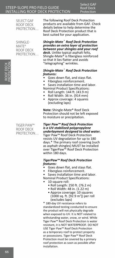
66
The following Roof Deck Protection products are available from GAF. Check details below to help determine the Roof Deck Protection product that is best suited for your application.
Shingle-Mate® Roof Deck Protection provides an extra layer of protection between your shingles and your roof deck. Unlike typical asphalt felts, Shingle-Mate® is fiberglass reinforced so that it lies flatter and avoids “telegraphing” wrinkles.
Shingle-Mate® Roof Deck Protection features:• Goes down flat, and stays flat.• Fiberglass reinforcement.• Saves installation time and labor.Nominal Product Specifications:• Roll Length: 144 ft. (43.9 m)• Roll Width: 36 in. (914 mm)• Approx coverage: 4 squares
(excluding laps)
Note: Shingle-Mate® Roof Deck Protection should not be left exposed to moisture or precipitation.
Tiger Paw™ Roof Deck Protection is a UV-stabilized polypropylene underlayment designed to shed water. Tiger Paw™ Roof Deck Protection resists UV degradation for up to 180 days.* The primary roof covering (such as asphalt shingles) MUST be installed over TigerPaw™ Roof Deck Protection within 180 days.
TigerPaw™ Roof Deck Protection features:• Goes down flat, and stays flat.• Fiberglass reinforcement.• Saves installation time and labor.Nominal Product Specifications:• 10-square roll: • Roll Length: 250 ft. (76.2 m) • Roll Width: 48 in. (1.22 m) • Approx coverage: 10 squares
(1000 sq. ft. [92.9 m2]) per roll (excludes laps)
* 180-day UV resistance refers to standardized testing conducted to ensure the product will not physically degrade when exposed to UV. It is NOT related towithstanding water, snow, or wind. While Tiger Paw™ Roof Deck Protection is water resistant, it is NOT WATERPROOF. DO NOT USE Tiger Paw™ Roof Deck Protection as a temporary roof to protect property or possessions. Tiger Paw™ Roof Deck Protection must be covered by a primary roof protection as soon as possible after installation.
ROO
F D
ECK
PRO
TEC
TIO
NSTEEP-SLOPE PRO FIELD GUIDE INSTALLING ROOF DECK PROTECTION
Select GAFRoof Deck Protection
SELECT GAFROOF DECK PROTECTION…
SHINGLE-MATE®ROOF DECK PROTECTION…
TIGER PAW™ROOF DECK PROTECTION…
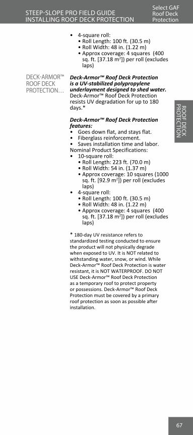
67
ROO
F DECK
PROTEC
TION
STEEP-SLOPE PRO FIELD GUIDE INSTALLING ROOF DECK PROTECTION
Select GAFRoof Deck Protection
DECK-ARMOR™ROOF DECK PROTECTION…
• 4-square roll: • Roll Length: 100 ft. (30.5 m) • Roll Width: 48 in. (1.22 m) • Approx coverage: 4 squares (400
sq. ft. [37.18 m2]) per roll (excludes laps)
Deck-Armor™ Roof Deck Protection is a UV-stabilized polypropylene underlayment designed to shed water. Deck-Armor™ Roof Deck Protection resists UV degradation for up to 180 days.*
Deck-Armor™ Roof Deck Protection features:• Goes down flat, and stays flat.• Fiberglass reinforcement.• Saves installation time and labor.Nominal Product Specifications:• 10-square roll: • Roll Length: 223 ft. (70.0 m) • Roll Width: 54 in. (1.37 m) • Approx coverage: 10 squares (1000
sq. ft. [92.9 m2]) per roll (excludes laps)
• 4-square roll: • Roll Length: 100 ft. (30.5 m) • Roll Width: 48 in. (1.22 m) • Approx coverage: 4 squares (400
sq. ft. [37.18 m2]) per roll (excludes laps)
* 180-day UV resistance refers to standardized testing conducted to ensure the product will not physically degrade when exposed to UV. It is NOT related to withstanding water, snow, or wind. While Deck-Armor™ Roof Deck Protection is water resistant, it is NOT WATERPROOF. DO NOT USE Deck-Armor™ Roof Deck Protection as a temporary roof to protect property or possessions. Deck-Armor™ Roof Deck Protection must be covered by a primary roof protection as soon as possible after installation.
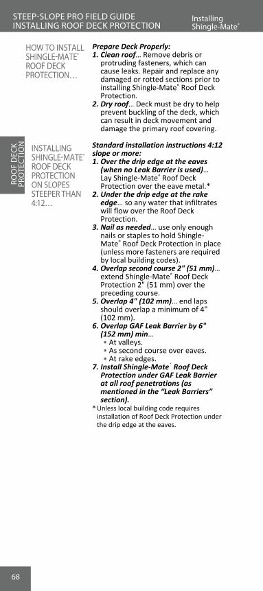
68
Prepare Deck Properly:1. Clean roof… Remove debris or
protruding fasteners, which can cause leaks. Repair and replace any damaged or rotted sections prior to installing Shingle-Mate® Roof Deck Protection.
2. Dry roof… Deck must be dry to help prevent buckling of the deck, which can result in deck movement and damage the primary roof covering.
Standard installation instructions 4:12 slope or more:1. Over the drip edge at the eaves
(when no Leak Barrier is used)… Lay Shingle-Mate® Roof Deck Protection over the eave metal.*
2. Under the drip edge at the rake edge… so any water that infiltrates will flow over the Roof Deck Protection.
3. Nail as needed… use only enough nails or staples to hold Shingle-Mate® Roof Deck Protection in place (unless more fasteners are required by local building codes).
4. Overlap second course 2" (51 mm)… extend Shingle-Mate® Roof Deck Protection 2" (51 mm) over the preceding course.
5. Overlap 4" (102 mm)… end laps should overlap a minimum of 4" (102 mm).
6. Overlap GAF Leak Barrier by 6" (152 mm) min…
• At valleys. • As second course over eaves. • At rake edges.7. Install Shingle-Mate® Roof Deck
Protection under GAF Leak Barrier at all roof penetrations (as mentioned in the “Leak Barriers” section).
* Unless local building code requires installation of Roof Deck Protection under the drip edge at the eaves.
ROO
F D
ECK
PRO
TEC
TIO
NSTEEP-SLOPE PRO FIELD GUIDE INSTALLING ROOF DECK PROTECTION
InstallingShingle-Mate®
HOW TO INSTALL SHINGLE-MATE®
ROOF DECK PROTECTION…
INSTALLING SHINGLE-MATE® ROOF DECK PROTECTION ON SLOPES STEEPER THAN 4:12…

69
Installing Shingle-Mate® or other GAF Roof Deck Protection is required for the Weather Stopper® Golden Pledge® and Silver Pledge® Limited Warranties.
• Deck-Armor™, Tiger Paw™, Shingle-Mate®, and other eligible GAF Roof Deck Protection are system accessories for Weather Stopper® System Plus Limited Warranty installations.
ROO
F DECK
PROTEC
TION
STEEP-SLOPE PRO FIELD GUIDE INSTALLING ROOF DECK PROTECTION
InstallingShingle-Mate®
WEATHER STOPPER® GOLDEN PLEDGE® AND SILVER PLEDGE® NOTE…
INSTALLING SHINGLE-MATE® ROOF DECK PROTECTION ON SLOPES STEEPER THAN 4:12…

70
ROO
F D
ECK
PRO
TEC
TIO
N
1. Best option: start with GAF Leak Barrier… the best protection on low-slope roofs is to apply a full 36" (914 mm) course of Leak Barrier at the eave.
2. Or start with Shingle-Mate® Roof Deck Protection… cut Roof Deck Protection down to a 19" (483 mm) width for the first course.
3. Install 36" (914 mm) course of Shingle-Mate® Roof Deck Protection… this course fully covers the first course.
4. Start third layer 17" (432 mm) from the eave…
• 17" (432 mm) from the eave, install another full course of Roof Deck Protection.
5. Continue up the roof… using a 17" (432 mm) exposure.
Installing GAF Leak Barrier at roof eaves is required on all Weather Stopper® Golden Pledge® and Silver Pledge® installations in the North and recommended in the South.
STEEP-SLOPE PRO FIELD GUIDE INSTALLING ROOF DECK PROTECTION
InstallingShingle-Mate®
HOW TO INSTALL SHINGLE-MATE®
ROOF DECK PROTECTION ON LOW SLOPES(2:12-4:12)…
WEATHER STOPPER® GOLDEN PLEDGE® AND SILVER PLEDGE® NOTE…
INSTALLING SHINGLE-MATE®
ROOF DECK PROTECTION ON LOW-SLOPES (2:12-4:12)…

71
Cutting… Use a straight blade knife, scissors, or sharp hook blade knife for cutting Tiger Paw™ Roof Deck Protection.
Type of seams… a “side lap” is the horizontal lap. An “end lap” is the vertical lap.
w Do NOT use nails or staples without caps. Use only plastic cap, corrosion-resistant nails, or staples with plastic caps. Fasteners should be long enough to penetrate at least 3/4" (19 mm) into wood decks or just through plywood or OSB decks. Fasteners must be flush to the deck and at a 90-degree angle to the roof deck.
w Provisions must be made in the roof design and installation to provide proper ventilation to avoid high humidity, condensation, and mold growth problems. A design professional must address the potential for moisture entrapment, excessive moisture build-up, and condensation. Local building codes in your area should also be reviewed for ventilation requirements.
Prepare Deck Properly…1. Clean roof… Remove debris or
protruding fasteners, which can cause leaks. Repair and replace any damaged or rotted sections prior to installing Tiger Paw™ Roof Deck Protection.
2. Dry roof… Deck must be dry to help prevent buckling of the deck, which can result in deck movement and damage the primary roof covering.
Install Leak Barrier…1. Where a waterproof underlayment
is needed... install GAF Leak Barrier at eaves, valleys, rakes, skylights, dormers, and other vulnerable leak areas. Follow Leak Barrier published application instructions.
2. Along the eaves and in the valleys... install the Leak Barrier before installing Tiger Paw™ Roof Deck Protection.
3. Along the rake... install Tiger Paw™ Roof Deck Protection, leaving 6"– 8" (152 mm–203 mm) minimum of the deck exposed, and then install the Leak Barrier over the Tiger Paw™ Roof Deck Protection.
4. In other areas... install the Leak Barrier over the Tiger Paw™ Roof Deck Protection (see WeatherWatch,® StormGuard,® or other GAF Leak Barrier published application instructions for more details).
ROO
F DECK
PROTEC
TION
STEEP-SLOPE PRO FIELD GUIDE INSTALLING ROOF DECK PROTECTION
Installing Tiger Paw™
VENTILATION CONSIDERATIONS…
INSTALLATION NOTE…
SEAMS…
FASTENERS…
HOW TO INSTALL TIGER PAW™ ROOF DECK PROTECTION…
InstallingShingle-Mate®

72
Alongrake, putnon-corrosivemetal drip edgeon top of Tiger-PawRoof Deck Protection
Tiger-Paw RoofDeck Protection
Along eaves, putTiger-Paw Roof DeckProtection on top ofnon-corrosive metaldrip edge.
6" (152 mm) end lap
36" (914 mm) min.between end laps
*
* Use GAF Leak Barrierif required
3" (76 mm) side lap
TM
TM
TM
STEEP-SLOPE PRO FIELD GUIDE INSTALLING ROOF DECK PROTECTION
Lay Out Tiger Paw™ Roof Deck Protection…1. Parallel to eave… Apply Tiger Paw™
Roof Deck Protection parallel to the eaves.
2. Install without wrinkles… Lay flat, cap nail flat. Do NOT stretch during installation.
3. Over drip edge at eaves… Lay Tiger Paw™ Roof Deck Protection over the eave metal unless local building code requires otherwise or if Leak Barrier is in place at eaves (see figure below).
4. Under drip edge at the rakes… Lay Tiger Paw™ Roof Deck Protection under the drip edge at the rake to help prevent wind uplift at the rake edge (see figure below).
Standard installation instructions 4:12 slope or greater…Overlap Tiger Paw™ Roof Deck Protection before fastening (see figure below).1. Overlap 3" (76 mm) at side lap…
Extend Tiger Paw™ Roof Deck Protection 3" (76 mm) over the preceding course. Use the line at top of printed grid to help align the 3" (76 mm) overlap.
2. Overlap 6" (152 mm) at end lap… End laps should overlap a minimum of 6" (152 mm) and be offset from adjacent end laps by 36" (914 mm).
3. Fasten... in accordance with Fastening section on next page.
ROO
F D
ECK
PRO
TECT
ION INSTALLING
TIGER PAW™ ROOF DECK PROTECTION ON SLOPES 4:12 OR GREATER…
Installing Tiger Paw™

73
Installing Tiger Paw™
STEEP-SLOPE PRO FIELD GUIDE INSTALLING ROOF DECK PROTECTION
Standard Installation Instructions 2:12 Slope To Less Than 4:12Install double coverage (see figure below).1. Overlap… a full 25.5" (648 mm) over
the underlying course.2. Continue up the roof… using a 22.5"
(572 mm) exposure.3. Overlap 6" (152 mm) at end lap
seams… and offset from adjacent end laps by 36" (914 mm).
4. Fasten... See Fastening.
Fasten Tiger Paw™ Roof Deck Protection… In accordance with installation instruc-tions below for all installations. Use only plastic cap corrosion-resistant nails or staples with plastic caps.1. Fasten side and end laps... 12" (305
mm) on center [use 6" (152 mm) on center for high wind].
2. Fasten in the field of the roll... with two staggered rows of fasteners spaced 24" (610 mm) on center (use 12" [305 mm] on center for high-wind areas).
ROO
F DECK
PROTEC
TION
Note: Special application for low slopes is the same as
Tiger Paw RoofDeck Protection
TM
Start with full36" (914mm)
width GAFLeak Barrieror a full 48"(1.22 mm)
wide sheet ofTiger-PawRoof DeckProtection.
(not shown)
TM
Alongrake, putnon-corrosivemetal drip edge ontop of Tiger PawRoof Deck Protection.
Along eaves,put leak barrier on topof non-corrosive metaldrip edge
TM
48"(1.22 m)
48"(1.22 m)
22.5"(572 mm)exposure
22.5"(572 mm)exposure
48"(1.22 m)
36"(914 mm)
FASTENING…
STANDARD INSTALLATION INSTRUCTIONS 2:12 SLOPE TO LESS THAN 4:12…

74
Always avoid scuffing… Normal walking on Tiger Paw™ Roof Deck Protection will not cause damage. However, scuffing can compromise its performance. Scuffing can be caused by twisting, kicking, or heavy rubbing of shoes against the Tiger Paw™ Roof Deck Protection.
If scuffing occurs… cover any scuffed areas with an additional layer of Tiger Paw™ Roof Deck Protection that exceeds the scuffed area by 6" (152 mm) on each side. Adhere the additional layer of Tiger Paw™ Roof Deck Protection with a moisture curable polyurethane adhesive that meets or exceeds ASTM C557. Follow the adhesive manufacturer’s instructions.
ROO
F D
ECK
PRO
TEC
TIO
NInstalling Tiger Paw™
STEEP-SLOPE PRO FIELD GUIDE INSTALLING ROOF DECK PROTECTION
Be careful when using Tiger Paw™ Roof Deck Protection under non-asphaltic roofing systems such as metal, slate, or tile. Components from these systems may cause excessive abrasion, scuffing, and sharp stress points, damaging the Tiger Paw™ Roof Deck Protection. For non-asphaltic systems, follow the primary roof covering manufacturer's recommended application instructions and the Tiger Paw™ published application instructions. Questions? Contact GAF at 1-800-ROOF-411.
PRECAUTIONS…
NOTE…
CAUTION…
75
1. Side Lap Detail must be taped… • Overlap second course 6" (152 mm)
in shingle fashion and fasten. • Use tape to completely cover all
side laps and all fasteners.2. End Lap Detail must be taped… • Overlap 12" (305 mm) at the end
lap and fasten. • Use tape to completely cover all end
laps and all fasteners.
Taped Seams… Use a butyl adhesive-based seam/cover tape or a waterproof cloth duct tape. Follow the tape manufacturer’s instructions.
Note: The long-term durability of these tapes varies by manufacturer and type. Be sure to use a tape that is stated to perform for the full time that Tiger Paw™ Roof Deck Protection will be exposed.
If roof may be exposed to high winds...1. Fasten side and end laps... use 6" (152
mm) on center.2. Fasten in the field of the roll... with two
staggered rows of fasteners spaced 12" (305 mm) on center.
3. Always apply tape… over all fasteners at the center of roll to help prevent rain or snow from entering at the fasteners.
4. Leaking... may result from exposed fasteners.
ROO
F DECK
PROTEC
TION
Installing Tiger Paw™
STEEP-SLOPE PRO FIELD GUIDE INSTALLING ROOF DECK PROTECTION
SPECIAL INSTALLATION INSTRUCTIONS – FOR MAXIMUM PROTECTION AGAINST EXPOSURE TORAIN/SNOW – FOR ALL SLOPES 2:12OR MORE…

76
HOW TO INSTALL DECK-ARMOR™
ROOF DECK PROTECTION…
INSTALLATION NOTE…
Cutting… use a straight blade knife, scissors, or sharp hook blade knife for cutting Deck-Armor™ Roof Deck Protection.
Type of Seams… a “side lap” is the horizontal lap. An “end lap” is the vertical lap.
w Do NOT use nails or staples without caps. Use only plastic cap, corrosion- resistant nails, or staples with plastic caps. Fasteners should be long enough to penetrate at least 3/4" (19 mm) into wood decks or just through plywood or OSB decks. Fasteners must be flush to the deck and at a 90-degree angle to the roof deck.
Prepare Deck Properly…1. Clean deck… Remove debris or
protruding fasteners, which can cause leaks. Repair and replace any damaged or rotted sections prior to installation of Deck-Armor™ Roof Deck Protection.
2. Dry deck… Deck must be dry to help prevent buckling of the deck, which can result in deck movement and damage the primary roof covering.
Install Leak Barrier…1. Where a waterproof underlayment is
needed, install GAF Leak Barrier. This ideally includes eaves, valleys, rakes, skylights, dormers, and other vulnerable leak areas. Follow Leak Barrier published application instructions.
2. Along the eaves and in the valleys, install the GAF Leak Barrier before installing Deck-Armor™ Roof Deck Protection.
3. Along the rake, install the GAF Leak Barrier over the Deck-Armor™ Roof Deck Protection.
4. In other areas, install the Leak Barrier over the Deck-Armor™ Roof Deck Protection (see GAF Leak Barrier published application instructions for more details).
Lay Out Deck-Armor™ Roof Deck Protection…1. Parallel to eave… apply Deck-Armor™
Roof Deck Protection parallel to the eaves.
2. Install without wrinkles… lay flat, nail flat. DO NOT stretch during installation.
3. Over drip edge at eaves… lay Deck-Armor™ Roof Deck Protection over the eave metal unless local building codes require otherwise, or if Leak Barrier is in place at eaves (see figures on next page).
4. Under drip edges at the rakes… lay Deck-Armor™ Roof Deck Protection under the drip edge at the rake to help prevent wind uplift at the rake edge (see figure next page).
ROO
F D
ECK
PRO
TEC
TIO
NInstaling Deck-Armor™
STEEP-SLOPE PRO FIELD GUIDE INSTALLING ROOF DECK PROTECTION
SEAMS…
FASTENERS…

77
Overlap Deck-Armor™ Roof Deck Protection Before Fastening...1. Overlap 3" (76 mm) at side lap…
extend Deck-Armor™ Roof Deck Protection 3" (76 mm) over the preceding course. Use the line at the top of printed grid to help align the 3" (76 mm) overlap.
2. Overlap 6" (152 mm) at end lap… end laps should overlap at least 6" (152 mm) and be offset from adjacent end laps by 36" (914 mm).
3. Fasten… see Fastening section (next page).
Install Double Coverage…1. Overlap… a full 28.5" (724 mm) overlap
over the underlying course.2. Continue up the roof… using a 25.5"
(648 mm) exposure.3. Overlap 12" (305 mm) at end lap
seams… and offset from adjacent end laps by 6' (1.83 m).
4. Fasten… see Fastening section (below).
ROO
F DECK
PROTEC
TION
Installing Deck-Armor™
STEEP-SLOPE PRO FIELD GUIDE INSTALLING ROOF DECK PROTECTION
INSTALLING DECK-ARMOR® ROOF DECK PROTECTION ON SLOPES 4:12 OR MORE…
INSTALLING DECK-ARMOR® ROOF DECK PROTECTION ON LOW SLOPES (2:12 TO LESS THAN 4:12) - 10 SQUARE ROLL…
Note: Special application for low slopes is the same as
Deck-Armor RoofDeck Protection
TM
Start with full36" (914mm)
width GAFLeak Barrieror a full 54"
(1.37mm)wide sheet of
Deck-ArmorRoof DeckProtection.
(not shown
TM
Alongrake, putnon-corrosivemetal drip edge ontop of Deck-ArmorRoof Deck Protection.
Along eaves,put leak barrier on topof non-corrosive metaldrip edge.
TM
36"(914 mm)
54"(1.37 m)
54"(1.37 m
54"(1.37 m)
25.5"(648 mm)exposure
25.5"(648 mm)exposure

78
FASTENING…
SPECIAL INSTALLATION INSTRUCTIONS FORMAXIMUM PROTECTION AGAINST EXPOSURE TO RAIN/SNOW FOR ALL SLOPES 2:12OR MORE…
Fasten Deck-Armor™ Roof Deck Protection… with plastic cap nails or staples with plastic caps in accordance with appropriate installation instructions below, for all installations:1. Fasten side and end laps… 12"(305
mm) on center [use 6" (152 mm) on center for high-wind areas].
2. Fasten in the field of the roll… with 2 staggered rows of fasteners spaced 24" (610 mm) on center [use 12" (305 mm) on center for high-wind areas].
Side Lap Detail… • Overlap second course 6" (152
mm) in shingle fashion and fasten (see Step 5).
• Completely cover all side laps and fasteners with tape.
End Lap Detail, must be taped… • Overlap 12" (305 mm) at the end
lap and fasten (see Step 5). • Use tape to completely cover all
end laps and all fasteners.
If roof may be exposed to high winds...1. Fasten in the field of the roll… with 2
staggered rows of fasteners spaced 6" (152 mm) on center.
2. Always apply tape… over all fasteners at the center of roll to help prevent rain or snow from entering at the fasteners.
3. Leaking… may result from exposed fasteners.
Taped Seams… use a butyl adhesive-based seam/cover tape or a waterproof cloth duct tape. Follow the tape manufacturer’s instructions.
Note: The long-term durability of these tapes varies by manufacturer and type. Be sure to use a tape that is stated to perform for the full time that Deck-Armor™ Roof Deck Protection will be exposed.
Always avoid scuffing… Normal walking on Deck-Armor™ Roof Deck Protection will not cause damage. However, scuffing can compromise the WATERPROOFING layer of Deck-Armor™ Roof Deck Protection and result in leaking. Scuffing can be caused by twisting, kicking, or heavy rubbing of shoes with weight pressing Deck-Armor™ Roof Deck Protection against the deck.
ROO
F D
ECK
PRO
TEC
TIO
NInstalling Deck-Armor™
STEEP-SLOPE PRO FIELD GUIDE INSTALLING ROOF DECK PROTECTION
PRECAUTIONS…
NOTE…

79
ROO
F DECK
PROTEC
TION
STEEP-SLOPE PRO FIELD GUIDE INSTALLING ROOF DECK PROTECTION
If scuffing occurs… cover any scuffed areas with an additional layer of Deck-Armor™ Roof Deck Protection that exceeds the scuffed area by 6" (152 mm) on each side. Adhere the additional layer of Deck-Armor™ Roof Deck Protection with a moisture-curable polyurethane adhesive that meets or exceeds ASTM C557. Follow the adhesive/sealant manufacturer’s instructions.
Be careful when using Deck-Armor™ Roof Deck Protection under non-asphaltic roofing systems such as metal, slate, or tile. Components from these systems may cause excessive abrasion, scuffing, and sharp stress points, damaging the Deck-Armor™ Roof Deck Protection. For non-asphaltic systems, follow the primary roof covering manufacturer’s recommended application instructions and the Deck-Armor™ published application instructions. Questions? Contact GAF at 1-800-ROOF-411.
Installing Deck-Armor™
CAUTION…

80
REVIEW #7
1. Why is it important to install Shingle Roof Deck Protection?
A. Secondary layer of protection in case of leaks. B. Protects shingles from wood resins. C. Levels the deck for a flat, even surface. D. All of the above.
2. What benefits to the installer does Shingle-Mate® Roof Deck Protection have over standard felts?
A. Goes down flat and stays flat for faster installation. B. Comes in multiple colors. C. Can be installed over an existing layer of shingles. D. All of the above.
3. True or False? The correct method of installing Shingle-Mate® Roof Deck Protection is under metal at rakes and over it at the eaves.
A. True B. False
4. True or False? Shingle-Mate® Roof Deck Protection should be installed under GAF Leak Barrier at all roof penetrations.
A. True B. False
5. GAF Roof Deck Protection can be fastened with... A. #10 metal screws. B. Plastic cap, corrosion resistant nails. C. Metal roofing nails. D. ASTM approved adhesive.
STEEP-SLOPE PRO FIELD GUIDE
ROO
F D
ECK
PRO
TEC
TIO
N

81
VENTILATIO
N
NEED
SVentilation Story
STEEP-SLOPE PRO FIELD GUIDE VENTILATION NEEDS
Proper attic ventilation is a design issue and a design professional should be consulted. Proper attic ventilation is not covered under GAF's warranties. The information provided is for general guidance only.
Proper attic ventilation systems allow a continual flow of outside air through the attic, protecting the efficiency of the insulation and helping to lower temperatures in the living space.
Ventilation is perhaps the most misunderstood area of roofing.
Question: “I never needed ventilation before; why do I need it now?”
Answer: Construction and buildings have changed...
1. Homes used to ventilate themselves… Heat and moisture used to escape through old windows, doors, and even right through the walls.
2. New materials seal-in buildings… • Insulation… new high-tech
materials, with high-tech installation methods, seal-off a building.
• Vapor barriers… non-breathing materials further seal-off buildings.
• Vinyl siding… with insulation traps moisture and heat in structures.
• High-tech windows… whether vinyl or wood, modern windows let very little air in or out of a structure.
PROPER ATTIC VENTILATION…
VENTILATION STORY…

82
NOW A ROOFING PROBLEM…
THE EXPERTS AGREE…
VENTILATE TO REDUCE HEAT…
VEN
TILA
TIO
N
NEE
DS
Ventilation and Heat
STEEP-SLOPE PRO FIELD GUIDE VENTILATION NEEDS
Result: Heat, moisture, and condensation that used to escape through walls and windows are now building up in the attic space.
Many major construction experts from architects to the U.S. Government agree that adequate ventilation is necessary on all buildings.
Excessive attic heat…1. Attics can heat up to 165°F (73.9°C)
or more.2. This heat radiates into the home… • Overheated attics mean
overheated homes. • Overheated homes can cost
homeowners thousands of dollars in air conditioning.
3. Attic heat can damage wood frames… Overheated attics subject structural woodwork to warping and cracking.
4. Attic heat can peel exterior paints…Excess heat inside a structure can peel exterior paints.
Overheated roof decks…1. Roof decks can reach over
170°F (77°C).2. Heat can reduce shingle life…
Overheated roof decks can actually “cook” roofing materials, reducing their effectiveness.
3. This can affect the shingle’s performance…
• Most major shingle manufactur-ers, including GAF, require ven-tilation meeting FHA minimum requirements.

83
Ventilation and Attic Moisture
STEEP-SLOPE PRO FIELD GUIDE VENTILATION NEEDS
MOISTURE TRAPPED IN AN ATTIC…
MOISTURE TRAVELS…
Moisture builds up in all structures. Moisture sources: • Showers, baths, and washing. • Cooking and cleaning. • Heating and cooling systems.
Where does this moisture go?1. Turns to vapor… Most of this moisture
will become vapor.2. Gets locked in… Modern construction
materials lock this moisture into the building.
3. Travels through ceilings… Once airborne, it will migrate through ceilings using natural convection.
4. Stops at first barrier… In most structures, this moisture stops at the roof deck.
5. Condenses on the deck… • Changes from vapor to water. • Forms on the interior of the deck
and on cold attic surfaces. • Drips onto dry insulation.
What does trapped moisture do?1. Will damage woodwork in attics… • Plywood will delaminate and rot. • OSB will expand and rot. • Structural frames will warp and rot.2. Reduces attic insulation R-value…
Excess moisture will drip down onto insulation and reduce its effectiveness.
3. Promotes mold and mildew… • Attic moisture can lead to mold and
mildew problems throughout the entire structure.
VENTILATE TO REDUCE EXCESS MOISTURE…
VENTILATIO
N
NEED
S
Hot, moist air rises
Moisture/Condensation Formson Cold Roof DeckATTIC MOISTURE
BUILDS UP WITHOUT PROPER VENTILATION…

84
1. Too much heat in the attic… Heat from the structure escapes to the attic.
2. This heat will melt a snow load… even when the outside temperatures are too cold for melting.
3. The ice dam is created… The melted snow runs down the roof, refreezing at the cold eave areas.
4. The water backs up the roof… water gets blocked by the ice dam, builds up, and often gets under shingles-causing leaks.
Reduce ice dams through adequate ventilation…1. Keep the attic cool... with
continuous ridge and adequate eave ventilation.
2. Meet or exceed the FHA ventilation requirements... and follow code requirements.
3. Install GAF Leak Barrier… to seal the eaves.
INADEQUATE VENTILATION CAN CAUSE ICE DAMS…
HOW TO SOLVE THIS PROBLEM…
VEN
TILA
TIO
N
NEE
DS
Ventilation and Ice Dams
STEEP-SLOPE PRO FIELD GUIDE VENTILATION NEEDS

85
1. True or False? Heat, moisture, and condensation that used to escape through walls and windows are now building up under roofing.
A. True B. False
2. GAF and most shingle manufacturers require what minimum requirement standard for ventilation?
A. VA B. OSHA C. FHA D. All of the above.
3. Which of the following is a potential source of moisture? A. Showers, baths, and washing. B. Cooking. C. Heating and cooling systems. D. All of the above.
4. What are the adverse effects of moisture trapped in an attic?
A. Promotes mold and mildew. B. Will damage plywood, OSB, and wood frames. C. Reduces attic insulation R-value. D. All of the above.
5. True or False? Inadequate attic ventilation is a contributing factor to ice damming.
A. True B. False
VENTILATIO
N
NEED
SREVIEW #8STEEP-SLOPE PRO FIELD GUIDE

86
Continuous ridge vents with continuous soffit vents is the best roof ventilation system.1. Offers full ventilation… Full
ventilation means air flow from the eave all the way to the ridge.
2. Works with natural convection… Using the natural force of hot air rising gives a no-maintenance system.
3. Cool, dry air replaces hot, moist air… Natural convection will draw in outside air at the soffit and push out hot, moist air at the ridge.
Cobra® Exhaust Vent benefits…1. Easy to install… Needs no end caps,
accessories or sealant; nails are provided.
2. Cobra® Ridge Vent on the entire peak... with continuous soffit or fascia vents creates uniform air flow for the underside of the roof deck.
3. Two ways to nail Cobra® Exhaust Vents...
• Hand Nailing... Cobra® Hand Nail coil comes with Cobra® Smart Nails™ for easy hand nailing of ridge caps and ridge vent together. Cobra® Hand Nail is slightly thicker than the Nail Gun version and has an NFVA of 16.9 sq. in. per lineal foot (35,774 sq. mm per lineal meter).
• Nail Guns... Cobra® Nail Gun coil comes with 1 ¾" (44 mm) coil nails. Cobra® Nail Gun is slightly thinner and has an NFVA of 14.1 sq. in. per lineal foot (29,847 sq. mm per lineal meter).
4. Base requires minimal cleaning… Cobra® Exhaust Vent will resist clogging due to a special binding agent that acts like a Teflon® coating.
5. Protects against insect infestation… Pests find it almost impossible to get through Cobra® Exhaust Vent.
6. Has a history in the field… Cobra® Exhaust Vent has been used by contractors for years on millions of roofs in North America.
7. Counts as an eligible accessory… on Weather Stopper® System Plus, Golden Pledge® and Silver Pledge® installations.
THE BEST WAY TO VENTILATE…
COBRA® EXHAUST VENT…
VEN
TILA
TIO
N
SOLU
TIO
NS
The Best Ventilation
STEEP-SLOPE PRO FIELD GUIDE VENTILATION SOLUTIONS

87
VENTILATION AND THE FHA/HUD…
FHA/HUD GUIDE LINES…
CALCULATINGTHE FHA1/300 RULE…
The Federal Housing Authority (FHA) and Housing and Urban Development (HUD) has established minimum ventilation requirements.
GAF recommends following the FHA/HUD requirements for proper ventilation. However, consult your local building codes for other ventilation requirements.
FHA/HUD Guide lines require: • Continuous soffits and continuous
ridge vents… The FHA/HUD requirements are based on air flow through both open soffits/fascias and ridges.
• A balanced system… 50% air flow through the soffit and 50% through the ridge.
• Calculate ventilation using the FHA 1/300 rule… This rule calls for a minimum of 1 sq. ft. of open ventilation per 300 sq. ft. of attic floor in Net Free Ventilation Area (NFVA) when using soffit to ridge venting.
VENTILATIO
N
SOLU
TION
SVentilation Guide lines
STEEP-SLOPE PRO FIELD GUIDE VENTILATION SOLUTIONS

88
VEN
TILA
TIO
N
SOLU
TIO
NS
Calculating the FHA 1/300 Rule
STEEP-SLOPE PRO FIELD GUIDE VENTILATION SOLUTIONS
Calculations:1. This attic needs 4 sq. ft. of NFVA: 1,200 sq. ft. ÷ 300 = 4 sq. ft. of NFVA2. Convert 1 sq. ft. to square inches: 12 in. x 12 in. = 144 in.2 3. Calculate attic's in.2 needs: 144 in.2 x 4 = 576 in.2 NFVA needed4. The FHA/HUD recommends a
balanced system of 50% NFVA at the soffit (as intake) and 50% NFVA at the ridge (as exhaust).
5. Calculate ridge needs: 576 in.2 x 50% = 288 in.2 NFVA at ridge
6. Calculate soffit needs: 576 in.2 x 50% = 288 in.2 NFVA at
soffit7. An easier way… find the lineal feet
of Cobra® Exhaust Vent needed using the chart on page 89.
A TYPICAL ATTIC OF 1,200 SQUARE FEET…

89
COBRA® ATTIC VENTILATION GUIDE LINES FOR THE FHA 1/300 RULE
AtticFloor
Square Feet
SquareInchesNFVA
at Ridge
Min. Feetof
Cobra®
ExhaustVent Hand
Nail (16.9in. perlineal foot)
Min. Feetof
Cobra®
ExhaustVent Nail
Gun (14.1
in. perlineal foot)
Min. Feet ofCobra® Rigid
Vent 3™, Snow
Country™ &Snow
CountryAdvanced™
(18.0 in. per
lineal foot
Min. Feetof
Cobra®
RidgeRunner®
(12.5 in.per
linealfoot)
Square Inches NFVA
at Soffit/ Eaves
1000 240 14.2 17 13.3 19.2 240
1100 264 15.6 18.7 14.7 21.1 264
1200 288 17.1 20.4 16 23 288
1300 312 18.5 22.1 17.3 25 312
1400 336 19.9 23.8 18.7 26.9 336
1500 360 21.3 25.5 20 28.9 360
1600 384 22.7 27.2 21.3 30.7 384
1700 408 24.1 28.9 22.7 32.6 408
1800 432 25.6 30.6 24 34.6 432
1900 456 27 32.3 25.3 36.5 456
2000 480 28.4 34 26.7 38.4 480
2100 504 29.8 35.7 28 40.3 504
2200 528 31.2 37.4 29.3 42.2 528
2300 552 32.7 39.1 30.6 44.2 552
2400 576 34.1 40.9 32 46.1 576
VENTILATIO
N
SOLU
TION
SVentilation Needs Chart
STEEP-SLOPE PRO FIELD GUIDE VENTILATION SOLUTIONS
Note: When rounding the amount of ridge vents up to the nearest foot, increase square inches of NFVA at soffit/eaves accordingly. This will help to maintain a balanced attic ventilation system.w In no event should the amount of
ridge (exhaust) ventilation exceed the amount of soffit (intake) ventilation.
• Install ridge vents across the entire ridge. • Install soffit, fascia, or eave vents across
the entire eave.• This combination will usually exceed the
FHA/HUD minimum requirements.
Note: If there are gable end vents and no soffit vents, do not install ridge vents. Gable end vents do not provide proper intake for ridge vents. Ridge vents require proper soffit, fascia, or eave intake ventilation. Do NOT ventilate the ridge without soffit vents.
VENTILATION SIMPLIFIED…
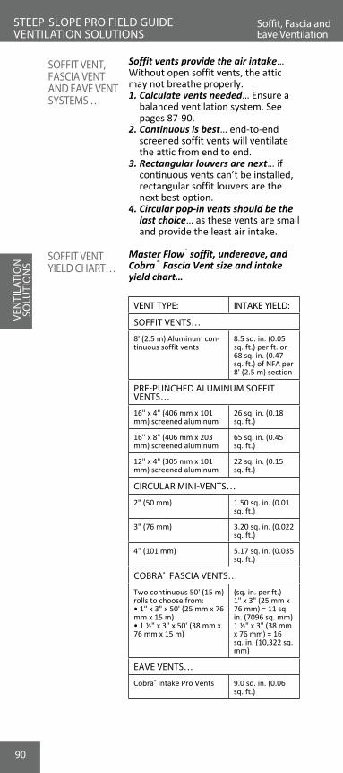
90
Soffit vents provide the air intake… Without open soffit vents, the attic may not breathe properly.1. Calculate vents needed… Ensure a
balanced ventilation system. See pages 87-90.
2. Continuous is best… end-to-end screened soffit vents will ventilate the attic from end to end.
3. Rectangular louvers are next… if continuous vents can’t be installed, rectangular soffit louvers are the next best option.
4. Circular pop-in vents should be the last choice… as these vents are small and provide the least air intake.
Master Flow® soffit, undereave, and Cobra® Fascia Vent size and intake yield chart…
VENT TYPE: INTAKE YIELD:
SOFFIT VENTS…
8' (2.5 m) Aluminum con-tinuous soffit vents
8.5 sq. in. (0.05 sq. ft.) per ft. or 68 sq. in. (0.47 sq. ft.) of NFA per 8' (2.5 m) section
PRE-PUNCHED ALUMINUM SOFFIT VENTS…
16" x 4" (406 mm x 101 mm) screened aluminum
26 sq. in. (0.18 sq. ft.)
16" x 8" (406 mm x 203 mm) screened aluminum
65 sq. in. (0.45 sq. ft.)
12" x 4" (305 mm x 101 mm) screened aluminum
22 sq. in. (0.15 sq. ft.)
CIRCULAR MINI-VENTS…
2" (50 mm) 1.50 sq. in. (0.01 sq. ft.)
3" (76 mm) 3.20 sq. in. (0.022 sq. ft.)
4" (101 mm) 5.17 sq. in. (0.035 sq. ft.)
COBRA® FASCIA VENTS…
Two continuous 50' (15 m) rolls to choose from:• 1" x 3" x 50' (25 mm x 76 mm x 15 m)• 1 ½" x 3" x 50' (38 mm x 76 mm x 15 m)
(sq. in. per ft.)1" x 3" (25 mm x 76 mm) = 11 sq. in. (7096 sq. mm)1 ½" x 3" (38 mm x 76 mm) = 16 sq. in. (10,322 sq. mm)
EAVE VENTS…
Cobra® Intake Pro Vents 9.0 sq. in. (0.06 sq. ft.)
SOFFIT VENT, FASCIA VENT AND EAVE VENT SYSTEMS …
SOFFIT VENT YIELD CHART…
VEN
TILA
TIO
N
SOLU
TIO
NS
Soffit, Fascia and Eave Ventilation
STEEP-SLOPE PRO FIELD GUIDE VENTILATION SOLUTIONS

91
STEEP-SLOPE PRO FIELD GUIDE VENTILATION SOLUTIONS
Soffit /Intake Ventilation
• Sizes include 16" x 4" and 16" x 8" (406 x 102 mm and 406 x 203 mm).
• Easy to install with pre-punched nail holes.
• Corrosion-resistant screened aluminum construction. Available in mill, brown, and white colors.
• Size: 16.5” x 9” x 5/8” (419 mm x 229
mm x 15.9 mm)• Helps prevent wildfire embers from
being drawn into the attic.• Provides 56 sq. in. (36,131 mm2) of NFA.Note: GAF's limited product warranty does not cover damage caused by fire, including wildfire embers. See Master Flow® Ventilation Products Limited Warranty for coverage and restrictions.
During installation, always wear appropriate safety glasses, gloves, hard hats, fall restraints, and other safety equipment to avoid injury.
1. Calculate vents needed… Ensure a balanced ventilation system. See pages 87-90.
2. Cut a 15” x 7.5” (391 mm x 191 mm) opening in the soffit or remove existing soffit vent. If replacing an existing soffit vent, ensure the vent is no larger than 16” x 8” (406 mm x 203 mm).
3. Center the EmberShield® Closeable Soffit Vent over the opening... making sure it is square with the structure. Fasten the vent in place through the pre-drilled holes using four included screws.
4. If painting (not required)... do not paint the screen or slider portion of the vent. After paint dries, always ensure proper movement of the slider.
5. During threat of wildfire... fully close the EmberShield® Vents to help prevent embers from being drawn into attic. Otherwise, the vents must always remain open for proper attic ventilation.
Note: Periodically open and close the vents to ensure they are functioning properly (see image below).
MASTER FLOW® INTAKE SOFFIT VENTS …
MASTERFLOW® EMBERSHIELD® CLOSEABLE SOFFIT VENT…
INSTALLING MASTERFLOW® EMBERSHIELD CLOSEABLE SOFFIT VENT…
VENTILATIO
N
SOLU
TION
S
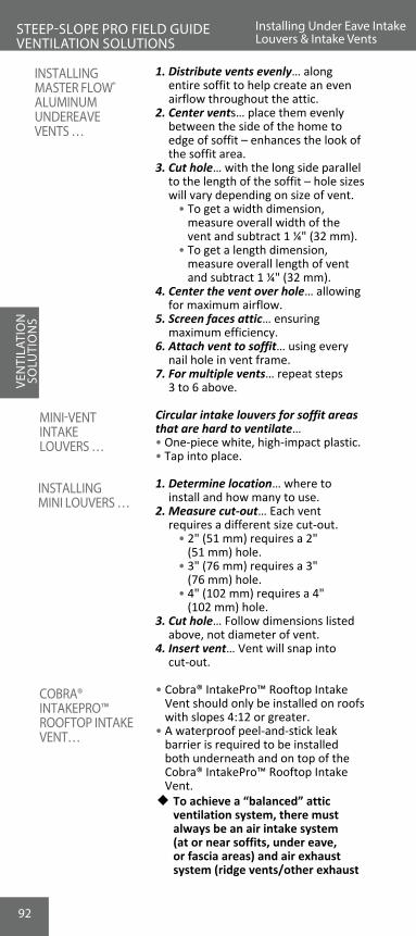
92
1. Distribute vents evenly… along entire soffit to help create an even airflow throughout the attic.
2. Center vents… place them evenly between the side of the home to edge of soffit – enhances the look of the soffit area.
3. Cut hole… with the long side parallel to the length of the soffit – hole sizes will vary depending on size of vent.
• To get a width dimension, measure overall width of the vent and subtract 1 ¼" (32 mm).
• To get a length dimension, measure overall length of vent and subtract 1 ¼" (32 mm).
4. Center the vent over hole… allowing for maximum airflow.
5. Screen faces attic… ensuring maximum efficiency.
6. Attach vent to soffit… using every nail hole in vent frame.
7. For multiple vents… repeat steps 3 to 6 above.
Circular intake louvers for soffit areas that are hard to ventilate…• One-piece white, high-impact plastic.• Tap into place.
1. Determine location… where to install and how many to use.
2. Measure cut-out… Each vent requires a different size cut-out.
• 2" (51 mm) requires a 2" (51 mm) hole.
• 3" (76 mm) requires a 3" (76 mm) hole.
• 4" (102 mm) requires a 4" (102 mm) hole.
3. Cut hole… Follow dimensions listed above, not diameter of vent.
4. Insert vent… Vent will snap into cut-out.
• Cobra® IntakePro™ Rooftop Intake Vent should only be installed on roofs with slopes 4:12 or greater.
• A waterproof peel-and-stick leak barrier is required to be installed both underneath and on top of the Cobra® IntakePro™ Rooftop Intake Vent.w To achieve a “balanced” attic
ventilation system, there must always be an air intake system (at or near soffits, under eave, or fascia areas) and air exhaust system (ridge vents/other exhaust
VEN
TILA
TIO
N
SOLU
TIO
NS
Installing Under Eave Intake Louvers & Intake Vents
STEEP-SLOPE PRO FIELD GUIDE VENTILATION SOLUTIONS
INSTALLING MASTER FLOW® ALUMINUM UNDEREAVE VENTS …
MINI-VENT INTAKE LOUVERS …
INSTALLING MINI LOUVERS …
COBRA® INTAKEPRO™ ROOFTOP INTAKE VENT…

93
VENTILATIO
N
SOLU
TION
SSTEEP-SLOPE PRO FIELD GUIDE VENTILATION SOLUTIONS
Cobra® IntakePro™ Vent
INSTALLING COBRA® INTAKEPRO™ VENT…
vents at or near the ridge). For proper ventilation, the amount of intake ventilation must equal the amount of exhaust ventilation. In no case should the amount of exhaust ventilation exceed the amount of intake ventilation. Consult local building codes for further specifications and requirements on proper attic ventilation.
1. Install metal drip edge... flashing at the eave to protect the roof deck/fascia junction.
2. Cut 1” (25 mm) air slot… in roof deck parallel to the eave edge. Measure up 6" (152 mm) and 7" (178 mm) up slope from the edge of the drip edge metal and mark these locations. Strike chalk lines parallel to the eave edge marking where the 1" (25 mm) wide air slot should be cut.
• Air slot MUST stop a minimum of 12” (305 mm) from terminating edges, side/end walls, and hip intersections
• Air slots MUST stop a minimum of 24” (610 mm) from valley intersections.
• The vent MUST always extend a minimum of 12” (305 mm) past any air slots.
Note: Cut through sheathing only. Always avoid cutting roof trusses and rafters. After cutting the air slot, clear all debris blocking access into the attic space. Be sure to flatten attic insulation near the air slot to allow for proper intake airflow near the air slot. Attic baffles may be used to help prevent insulation from blocking intake airflow into the attic space.3. Install a minimum 18” (457 mm)...
wide leak barrier. Align peel-and-stick leak barrier flush to the edge of the roof on top of the drip edge metal (or below if required by code) and re-open air slot cut previously.
4. Place end cap fabric… overhanging halfway over the terminating edge and parallel to the eave drip edge fastening the fabric to the roof deck using two roofing nails, one high and one low.
5. Position the vent… on top of the fabric end cap and flush to the terminating edge and eave drip edge with the front face flush with the drip edge metal below.

94
FOR TERMINATIONS AT GABLE/RAKE EDGES…
FOR TAPERED TERMINATIONS AT SIDE/END WALLS AND STRUCTURES/CHIMNEYS…
VEN
TILA
TIO
N
SOLU
TIO
NS
Cobra® IntakePro™ Vent
STEEP-SLOPE PRO FIELD GUIDE VENTILATION SOLUTIONS
Note: Using the included 1 ¾" (44 mm) pneumatic coil nails, fasten the vent every 6" (152 mm) along the pre-marked nail line and fasten every 12" (305 mm), approximately 1.5" (38mm) down from the up-slope edge of the vent. Do NOT nail within 1" (25 mm) from the side, top, or bottom edges of the vent. Nails must always penetrate through plywood or OSB decks, or at least ¾" (19 mm) into wood planks.6. Cover the end of the vent… with the
previously installed fabric end cap by wrapping the overhanging end fabric neatly over the vent, ensuring it completely closes the open end.
7. Install vent… toward the termination point.
Note: When installing multiple rolls, adjoin the rolls by butting them tightly together. There should be NO gap between adjoining sections. For optimal appearance, GAF recommends installing Cobra® IntakePro™ Rooftop Intake Vent the entire length of the eave. The vent must always extend a minimum of 12" (305 mm) past any air slots.
• Cover the end of the vent run using the included fabric end cap in the same manner as the start of the vent run as described in Step 6.
• Continue installing the vent to the desired tapered termination point. Mark and cut a 45-degree “V” shape out of the vent using a sharp utility knife and discard.

95
VENTILATIO
N
SOLU
TION
SSTEEP-SLOPE PRO FIELD GUIDE VENTILATION SOLUTIONS
Cobra® IntakePro™ Vent
• The remaining free end will be used to provide the tapered termination as shown below. Using the remaining free end of the vent, rotate and position it so its thin side is nearest to the termination point.
• Nail end cap fabric down to the roof deck underneath the vent leaving half of the fabric exposed as shown below.
• Finish by wrapping the exposed end cap fabric back over the vent to cover the open portion and nail fabric in place with two roofing nails.
8. Install leak barrier… completely covering the top of the vent and extending from the eave edge to a minimum of 24” (610mm) in from the building’s warm wall. The leak barrier should NOT overhang the vent. Install rake drip edge if necessary.

96
VENTILATING CATHEDRAL CEILINGS…
9. Begin starter course installation… The starter course and first course of field shingles should overhang the front edge of the Cobra® IntakePro™ Rooftop Intake Vent by ¼" – ¾" (6 mm – 19 mm) to provide a drip edge. Using the included 1 ¾" (44 mm) pneumatic coil nails, fasten the starter strip and field shingles as per manufacturer’s installation instructions. Ensure the field shingles are NOT fastened into the open air intake slot below.
Note: For installations where extra-thick or designer shingles are used, longer fasteners may be required to penetrate through the plywood or OSB decks, or at least ¾" (19 mm) into wood planks.
1. Use the floor space square footage… when calculating for the FHA 1/300 rule, use the floor square footage to figure ventilation needs.
2. To allow batt insulation to expand... leave at least 2" (51 mm) air space between the roof deck and the underdeck insulation to allow for airflow or install ThermaCal® ventilated roof insulation above the deck.
3. When re-roofing… be certain to clear the existing airway for ventilation. Many cathedral ceilings were built before ventilation was well understood.
VEN
TILA
TIO
N
SOLU
TIO
NS
Ventilating Cathedral Ceilings and Hip Roofs
STEEP-SLOPE PRO FIELD GUIDE VENTILATION SOLUTIONS

97
VENTILATIO
N
SOLU
TION
SSTEEP-SLOPE PRO FIELD GUIDE VENTILATION SOLUTIONS
Cobra® Exhaust Vent
VENTILATING HIP ROOFS…
Due to their short ridge lines, properly ventilating a hip style roof can be difficult using only ridge and soffit venting.1. Not enough exhaust ventilation… The
1,200 sq. ft. (111.5 m2) attic needs 17' (5.18 m) of Cobra® Exhaust Vent. What if the hip roof only has 10' (3.05 m) of ridge?
2. Install Cobra® Hip Vents… within 12"-18" (305-457 mm) of ridge to add exhaust ventilation or install roof louvers.
Note: Roof louvers are also commonly called "mushroom vents," "soldier," "airhawks," "cake pans," and "box vents."3. Add five roof louvers on a typical
1,200 square foot (111.5 m2) attic… to meet the FHA minimum 1/300 rule.
HOW TO INSTALL COILED COBRA® EXHAUST VENTS…
1. Structures without ridge boards… Make a 1" (25 mm) cut along both sides of the ridge.
2. Structures with ridge boards… Cut 1 ¾ " (44 mm) on each side when there is a ridge board.
3. Leave 6" (152 mm) of uncut sheathing at gable ends… leaving 6" (152 mm) protects the structure from wind-driven rains.
4. Cut the sheathing only… For safety and structural integrity, set the correct blade depth.
5. Cover entire ridge with Cobra® Exhaust Vent… For weather protection, best appearance, and to prevent dead-air pockets, cover the entire ridge with ridge vent.
Note: When using ridge ventilation, do not cover ridge vent slot/opening with Leak Barrier material or other underlayments.6. Caulk lengths together if desired…
If larger lengths are needed, caulk ends to seal together.
7. Install ridge cap shingles over Cobra® Exhaust Vent… Use Cobra® Smart Nails™ supplied with every package of Cobra® Exhaust Vent (2 ¼" [57 mm] nails).
8. Do not overdrive nails… Leave ¾" (19 mm) (5/8" [16 mm] on nail gun version) between ridge cap and deck. Overdriving can leave an uneven ridge profile.

98
VEN
TILA
TIO
N
SOLU
TIO
NS
HOW TO INSTALL COILED COBRA®
EXHAUST VENTS…
Cobra® Exhaust Vent
STEEP-SLOPE PRO FIELD GUIDE VENTILATION SOLUTIONS
9. Over laminated shingles… Caulk the underside of the outer edge to the shingles to completely seal.
Note: Minimum roof slope – 2:12 Maximum roof slope – 20:12
w Do not install Cobra® Exhaust Vents along the down-slope hip rafters (hip legs).

99
VENTILATIO
N
SOLU
TION
S
INSTALLING COILED COBRA®
EXHAUST VENTS…
STEEP-SLOPE PRO FIELD GUIDE VENTILATION SOLUTIONS
Cobra® Exhaust Vent
Seal SeamsWith Caulking
-....__....,�-+----+--•�
Leave 6" At Ends
6"
Cut back 1" (25 mm) on both sides
Leave 6” (152 mm) at ends
Install Cobra® Ridge Vent
Seal Seams With Caulking
Fasten shingle over Cobra® Exhaust Vent. Only use a nail gun when installing Cobra® Nail Gun coils.

100
• Only for roofs with slopes between 3:12 and 12:12. Do NOT install Cobra® Hip Vent on ridges.
• Use minimum 3/8” (10 mm) plywood or OSB decking. Wood decks must be well-seasoned and supported, having a maximum 1/8” (3 mm) spacing and using a minimum nominal 1” (25 mm) thick lumber with a maximum 6” (152 mm) width, having adequate nail-holding capacity and a smooth surface.w To ensure proper exhaust
ventilation and weather resistance, NEVER cut hip air slots below the midpoint of the hip. Do NOT cut air slots less than 24” (610 mm) in from the building’s warm exterior wall (see Step 2, “Cutting Hip Air Slots”). ALWAYS install Cobra® Hip Vent with the “Towards Peak” arrows on the top surface of the vent pointing up towards the peak of the roof. If ridge ventilation will be installed, always install the ridge vent to the end of the ridge BEFORE installing Cobra® Hip Vent to allow for a proper tie-in at the hip and ridge junction.
To achieve the necessary “balanced” ventilation system with Cobra® Hip Vent, there must be an air intake system (i.e., soffit, fascia, or undereave vents). For proper ventilation, the amount of intake ventilation must equal the amount of exhaust ventilation.1. Calculate a balanced ventilation
system... Cobra® Hip Vent has 9 square inches of net free ventilating area (NFVA) per lineal foot (19,051 mm2) of NFVA per lineal meter. Determine the minimum amount of NFVA needed for a balanced ventilation system for the entire attic space, using the following formula: (Sq.ft.of attic floor space)/300 = Total min.sq.ft.of NFVA needed
Note: ½ of the NFVA should be provided at the top of the roof (ridge and/or hip vents) and ½ of the NFVA should be at the bottom of the roof (i.e., soffit, fascia, or undereave vents). The amount of exhaust ventilation should NEVER exceed the amount of intake ventilation.2. Determine… minimum amount
of Cobra® Hip Vent required. If a ridge vent is to be installed, first determine how much NFVA will be provided by the ridge vent.
VEN
TILA
TIO
N
SOLU
TIO
NS
Cobra® Hip Vent Exhaust Vent for Hip Roofs
STEEP-SLOPE PRO FIELD GUIDE VENTILATION SOLUTIONS
COBRA® HIP VENT EXHAUST VENT FOR HIP ROOFS…
INSTALLING COBRA® HIP VENTS…

101
VENTILATIO
N
SOLU
TION
SSTEEP-SLOPE PRO FIELD GUIDE VENTILATION SOLUTIONS
Cobra® Hip Vent Exhaust Vent for Hip Roofs
• To determine how much NFVA must be provided by hip vents, subtract the NFVA to be provided by the ridge vent from ½ of the total NFVA calculated in Step 1. If ridge vents are not used, then the hip vents alone must provide ½ the total NFVA calculated above.
• Determine the length of Cobra® Hip Vents required: sq.ft.(m2 )of NFVA hip venting needed x 144/9 (1,000,000/19,051) = Minimum feet (meters) of Cobra® Hip Vents required
Note: This calculation does NOT include the additional Cobra® Hip Vent recommended for installation on the non-vented hip area to achieve the best appearance. Add the amount of Cobra® Hip Vent needed to cover the non-vented lower hip area to what is calculated as needed above to determine the total amount of hip vent you will need to purchase for your roof.3. Determine… the amount of intake vent
required using the following formula: • X = NFVA (sq.in.per lin.ft.[mm2
per lin.m])of soffit, fascia, or undereave intake vents
• ½ × (total minimum sq.ft. [m2 ] of NFVA needed) × 144/X [1,000,000/X] = Minimum lineal feet (lineal meters) of the soffit, fascia, or undereave intake vents
Note: The ventilation calculations above are based on a minimum 1:300 attic ventilation requirement. ALWAYS consult local building codes for attic ventilation requirements in your area.4. Cut hip air slots… 2 ½” wide x 36”
long (64 mm x 914 mm) SEPARATED hip air slots. The hip air slots must be separated 12” (305 mm) apart to ensure that the structural integrity of the roof is not compromised.
• Cut one hip air slot 2 ½” x 36” (64 mm x 914 mm) for each of the 4’ (1.2 m) Cobra® Hip Vents sections needed to provide the length of hip venting calculated in Step 1 and Step 2.
Note: Cut through sheathing only. Do NOT cut roof trusses, the hip rafters, or any other rafters. Do NOT cut continuous air slots along the hip areas of the roof. Do NOT cut hip air slots BELOW the midpoint of the hip.

102
5. First hip air-slot… Starting 12” (305 mm) down from the top of the hip, mark and cut a 2 ½” x 36” (64 mm x 914 mm) air slot centered on the hip to provide a ½” x 36” (13 mm x 914 mm) opening on each side of the hip rafter. Remove any sheathing, underlayments, and shingles from the slot.
• On plywood /OSB roof decks, where a sheathing seam intersects the hip air slot, stop cutting the air slot 2” (51 mm) before the seam and continue cutting the slot 2” (51 mm) after the seam. Then, proceed with cutting down to the previously marked 36” (914 mm) point.
• Subsequent Air Slots… After the top hip air slot is cut, working down the hip, leave 12” (305 mm) of uncut hip. Mark and cut another 2 ½” x 36” (64 mm x 914 mm) air slot centered on the hip to provide a ½” x 36” (13 mm x 914 mm) opening on each side of the hip rafter.
• Continue marking and cutting separated hip air slots, as needed, until reaching the midpoint of the hip. Depending on the length of the roof’s hip and ventilation needs, the bottom hip slot nearest the midpoint may be less than 36” (914 mm) in length.
• Always remember: Do NOT cut slots closer than 24” (610 mm) to the building’s warm exterior wall.
Note: Re-nail or reinforce any tongue-and-groove decking or plywood/OSB sheathing in the area of the hip air slots, as needed.6. Install two cap shingles… at the base
of the hip, nearest the eave edge.7. Install Cobra® Hip Vent… over the
entire length of the hip, making sure that the vent always extends past the bottom and top hip slot openings by at least 12” (305 mm).
VEN
TILA
TIO
N
SOLU
TIO
NS
Cobra® Hip Vent Exhaust Vent for Hip Roofs
STEEP-SLOPE PRO FIELD GUIDE VENTILATION SOLUTIONS

103
VENTILATIO
N
SOLU
TION
SSTEEP-SLOPE PRO FIELD GUIDE VENTILATION SOLUTIONS
8. Center and conform… Cobra® Hip Vent over the shingles, placing it firmly against the roof surface starting at the bottom of the hip nearest the eave.w Always be sure that Cobra® Hip Vent
is oriented so that the “Towards Peak” arrows on the top surface of the vent point towards the peak of the roof to help prevent weather infiltration and leaking.
9. Fasten vent… using the included 1 3/4” (44 mm) coil nails (use longer nails if necessary). Nails must always penetrate through plywood or OSB decks or at least 3/4” (19 mm) into wood planks and should be driven flush with the surface of the Cobra® Hip Vent.
• Attach the first Cobra® Hip Vent section using appropriate coil nails at the pre-marked 6” (152 mm) increment nail gun targets. These targets are marked “Fasten Vent Here” on the vent. Continue fastening Cobra® Hip Vent up the hip towards the peak. Apply the subsequent sections using the vent’s overlap/underlap tabs.
Note: For maximum weather resistance, always ensure that Cobra® Hip Vent is fastened tightly and snugly to the roof shingles below.10. Installations WITHOUT Ridge Vent... Terminate the top Cobra® Hip Vent
section at the top of the hip and approximately level to the ridge line. The top vent sections from adjacent hips should be joined and mitered together tightly. Install a 3” x 12” (76 mm x 305 mm) strip of self-adhering leak barrier over all the junctions between the mitered vents.
11. Installations WITH Ridge Vent... Always install the ridge vent before
the Cobra® Hip Vent. Cut out the template printed on the outside of the Cobra® Hip Vent package. See the Cobra® Hip Vent to Ridge Vent Miter Cut Instructions included inside the package. With the top section of the Cobra® Hip Vent properly sized and butted tightly to the ridge vent, fasten in accordance with Step 3. Install a 3” x 12” (76 mm x 305 mm) strip of self-adhering leak barrier over all junctions between the hip vent and ridge vent. Proceed with installing cap shingle.
12. Install cap shingles… directly over the Cobra® Hip Vent, using 1 3/4” (44 mm) pneumatic coil nails (included) or longer nails if necessary. Follow the nail line on the top of the vent to make sure to fasten the cap shingles in the right location.
Cobra® Hip Vent Exhaust Vent for Hip Roofs

104
INSTALLING COBRA® EXHAUST VENT ON SHED-STYLE ROOFS…
Ventilate Shed Roofs… • When the roof is over a heated area. • When the roof is over an air-
conditioned area.
1. Minimum roof slope 4:12, maximum roof slope 20:12.
2. Cut a 2" (51 mm) slot in the deck… as close to the ridge or top as possible.
3. Keep slot at least 6" (152 mm) back from the roof edges… to reduce the chance of wind-driven rain entering.
4. Install shingles up to the slot… Install shingles, cutting the top course even with the vent slot.
5. Install half width of Cobra® Exhaust Vent… Cut the 10 ½ " (267 mm) Cobra® Exhaust Vent in half and install over the entire roof width, covering the vent slot and the shingles.
6. Cover Cobra® Exhaust Vent with metal flashing… Install continuous non-corroding metal flashing that:
• Completely covers the Cobra® Exhaust Vent.
• Extends 1" (25 mm) past the Cobra® Exhaust Vent at the roof edge.
• Extends at least 5" (127 mm) up the adjoining wall.
• Is minimum 24-gauge corrosion-resistant metal.
7. Counter flashing… Cover the metal flashing with counter flashing or siding made from materials that will last as long as the shingles being installed.
8. Install cap shingles… Set cap shingles over metal flashing in plastic cement to fully cover metal flashing.
SHED-STYLE ROOF VENTILATION…
VEN
TILA
TIO
N
SOLU
TIO
NS
Cobra® Exhaust Vent On Shed Roofs
STEEP-SLOPE PRO FIELD GUIDE VENTILATION SOLUTIONS

105
VENTILATIO
N
SOLU
TION
SNOTES

106
VEN
TILA
TIO
N
SOLU
TIO
NS
Ventilating One- Sided Gable Roofs
STEEP-SLOPE PRO FIELD GUIDE VENTILATION SOLUTIONS
VENTILATING ONE-SIDED GABLE ROOFS…
Install Cobra® Exhaust Vent when ar-chitectural design leaves a gable-style roof plane with half a ridge.
1. Minimum roof slope 4:12, maximum roof slope 20:12.
2. Cut back vent slot… 1 ¾" (44 mm) at the gable roof peak.
3. Install Deck-Armor™ Roof Deck Protection or other GAF Roof Deck Protection up to the vent slot.
4. Apply shingles… cutting flush to the vent slot.
5. Create nail plates… using 1" x 3" (25 x 76 mm) wood pieces cut to 4" (102 mm) lengths.
6. Install nail plates 3' (914 mm) on center… parallel to the rafters across the entire ridge.
7. Cut Cobra® Exhaust Vent in half… to install at the ridge.
8. Cut Cobra® Exhaust Vent to 3" (76 mm) lengths… to install between the nail plates.
9. Install Cobra® Exhaust Vent… • Between the nail plates. • Flush to the back edge of the
gable. • Across the entire ridge.10. Install metal flashing over
ridge vent… install custom-made metal flashing.
• 24-gauge minimum, non-cor-roding metal.
• Extend over Cobra® Exhaust Vent at least 1" (25 mm) down slope.
• Extend at least 4" (102 mm) down the gable back or face.
11. Fasten metal to nail plates… nail the metal flashing to the 1"x 3" (25 x 76 mm) nail plates across the deck.
12. Install ridge cap shingles… set ridge cap shingles over metal flashing in plastic cement to fully cover the face nails.

107
VENTILATIO
N
SOLU
TION
SSTEEP-SLOPE PRO FIELD GUIDE VENTILATION SOLUTIONS
Ventilating One- Sided Gable Roofs
INSTALLING COBRA® EXHAUST VENT ON ONE-SIDED GABLE ROOFS…
FINISH WITH METAL FLASHING…

108
Cobra® Rigid Vent 3™, Cobra® Snow Country™, and Cobra® Snow Country Advanced™ are GAF’s hard plastic ridge vents…
w Cobra® Rigid Vent 3™ Exhaust Vents... designed for installation in warm climates.
w Cobra® Snow Country™ and Cobra® Snow Country Advanced™ Exhaust Vents for harsh winter climates… Snow Guard™ Filter reduces the risk of snow infiltration in harsh winter climates.
Benefits of GAF’s hard plastic rigid vents…1. Breathe more… Cobra® Rigid Vent
3™, Cobra® Snow Country™, and Cobra® Snow Country Advanced™ Ridge Vents allow more air flow than most available ridge vents.
2. Weathertight… Like Cobra® Exhaust Vent, Cobra® Rigid Vent 3™, Cobra® Snow Country™, and Cobra® Snow Country Advanced™ Exhaust Vents pass the tough Miami-Dade County wind-driven rain tests.
3. Easy to install… • No end caps or accessories. • Roof conforming end caps allow
installation on slopes 3:12 to 16:12.
• Easy Tear™ feature allows for hand-tearing of parts every 3" (76 mm). No knives necessary.
• Cobra® Snow Country Advanced™ and Cobra® Rigid Vent 3™ Exhaust Vents include 3" (76 mm) ring shank nails on the baffle for proper vent and ridge cap shingle installations.
4. Cobra Rigid Vent 3™ and Snow Country Advanced™ are available in both 12" (305 mm) and 9" (227 mm) widths.
These vents can be counted as an eligible accessory… on GAF enhanced warranties: Weather Stopper® Golden Pledge® and Silver Pledge®, and System Plus Limited Warranties.
COBRA®
RIGID VENT 3™, COBRA® SNOW COUNTRY™, AND COBRA® SNOW COUNTRY ADVANCED™…
VEN
TILA
TIO
N
SOLU
TIO
NS
Cobra® Rigid Vent 3™, Cobra® Snow Country™, and Cobra® Snow Country Advanced™
STEEP-SLOPE PRO FIELD GUIDE VENTILATION SOLUTIONS
WEATHER STOPPER® SYSTEM PLUS AND WEATHER STOPPER® GOLDEN AND SILVER PLEDGE® NOTE…

109
Cobra® Rigid Vent 3™, Cobra® Snow Country™, and Cobra® Snow Country Ad-vanced™ Exhaust Vents are installed in the exact same manner… Use the following instructions for all of these ridge vents:1. Discover if there is a ridge board… • Ridge boards determine the size of
the ridge opening. Do not exceed recommended cut size.
2. Cut ridge opening… • Roofs with ridge boards… cut back
1 5/8" (41 mm) on each side of the ridge to make a 3 ¼" (82 mm) opening.
• Roofs without ridge boards… cut back 7/8" (22 mm) on each side to make a 1 ¾" (44 mm) opening.
3. Leave 6" (152 mm) at each end of opening… this helps prevent wind-driven rain from entering at ends.
4. Install sections… • Center over the ridge. • Align using the male-female
alignment tabs.Note: For installations in cold weather, leave 1/8" (3 mm) gap between overlap and underlap of each vent section to allow for expansion.5. Nail through the supported nailing
holes… • As with shingles, nails must
completely penetrate sheathing, or at least ¾" (19 mm) into wood plank decks.
• For Cobra® Snow Country Advanced™ and Cobra® Rigid Vent 3™ Exhaust Vents, use included 3" (76 mm) ring shank nails located on the baffle to fasten the vent to the deck.
HOW TO INSTALL COBRA®
RIGID VENT 3™, COBRA® SNOW COUNTRY™, AND COBRA® SNOW COUNTRY ADVANCED™ EXHAUST VENTS…
VENTILATIO
N
SOLU
TION
SSTEEP-SLOPE PRO FIELD GUIDE VENTILATION SOLUTIONS
Cobra® Rigid Vent 3™, Cobra® Snow Country™, and Cobra® Snow Country Advanced™

110
• For Cobra® Snow Country™ Exhaust Vents, use at least 1 ¾" (44 mm) roofing nails to fasten the vents to the deck. 3" (76 mm) ring shank nails are recommended for increased wind uplift resistance.
6. Install over the entire ridge… Cover the ridge from end to end with vent.
• Ensures weather-tight ends. • Gives the best finished
appearance.7. Use EasyTear™ feature to finish the
last section to length… • On the underside of the vent,
select the support rib nearest the end of your desired length.
• Locate the baffle cut mark on the top side of the baffle. This is clearly marked on the baffle.
• Grasp the baffle with both hands on each side of the cut mark and snap. Proceed with locating the baffle cut mark on the other side of the vent and snap with both hands.
• After the baffles are torn, fold the vent back and forth along the tear seam until it breaks apart. If using Snow Country™ or Snow Country Advanced™ Exhaust Vents, use a utility knife to cut the Snow Guard™ Filter.
Note: If the final vent section cannot be sized using the EasyTear™ feature, cut the vent to desired length using a utility knife.8. Fit the finished end to the outside…
Place the vent section with built-in end cap section to the outside to prevent weather infiltration.
• Butt the unfinished end to the last section.
• Seal the joint with caulking.9. Over laminated shingles… caulk the
underside of the outer baffles to the shingles to completely seal.
10. Install cap shingles… • Nail in the inscribed nail line. • For Cobra® Rigid Vent 3™ and
Cobra® Snow Country Advanced™ Exhaust Vents, use included 3" (76 mm) ring shank nails supplied on the baffle of the vent.
• For Cobra® Snow Country Advanced™ Exhaust Vents use 2 ¼" (57 mm) roofing nails, or nails long enough to penetrate through sheathing or ¾" (19 mm) into wood planks. 3" (76 mm) ring shank nails are recommended for increased wind uplift resistance.
VEN
TILA
TIO
N
SOLU
TIO
NS
STEEP-SLOPE PRO FIELD GUIDE VENTILATION SOLUTIONS
HOW TO INSTALL COBRA®
RIGID VENT 3™, COBRA® SNOW COUNTRY™, AND COBRA® SNOW COUNTRY ADVANCED™ EXHAUST VENTS…
Cobra® Rigid Vent 3™, Cobra® Snow Country™, and Cobra® Snow Country Advanced™

111
HOW TO INSTALL COBRA® RIGID VENT 3™, COBRA® SNOW COUNTRY™, AND COBRA® SNOW COUNTRY ADVANCED™ EXHAUST VENTS…
VENTILATIO
N
SOLU
TION
STEEP-SLOPE PRO FIELD GUIDE VENTILATION SOLUTIONS
Cobra® Rigid Vent 3™, Cobra® Snow Country™, and Cobra® Snow Country Advanced™
Use 3" (77 mm) interval EasyTear™ feature to custom-size the vent
Install Sections Using Alignment Tabs
Center Over Ridge: Nail Through Supported Nail Holes

112
Cobra® Ridge Runner® Ridge Vent provides the performance of a baffled ridge vent with the easy installation of a roll vent…w Cobra® Ridge Runner® is designed for
installation in both warm and cold climates.
1. Looks Terrific… 5/8" (16 mm) height, shingle-over design blends into the ridge line.
2. Weather Fighter™ Filter… helps prevent all types of weather infiltration.
3. Fast and Easy to Install… • Fully nailable and gunnable;
simply roll out and fasten with included 1 ¾" (44 mm) coil nails.
• EasyTear™ feature allows hand- tearing of product in 12" (305 mm) increments. This cuts down on waste and saves time.
• Extra-flexible hinge allows installation on 3:12 to 16:12 slopes.
These vents can be counted as an eligible accessory… on GAF enhanced warranties: Weather Stopper® Golden Pledge® and Silver Pledge®, and System Plus Limited Warranties.
1. Discover if there is a ridge board… • Ridge boards determine the size
of the ridge opening. Do not exceed the recommended cut size.
2. Cut ridge opening… • Roofing without ridge boards…
cut back 7/8" (22 mm) on each side of the ridge to make a 1 ¾" (44 mm) opening.
• Roofing with a ridge board… cut back 1 5/8" (41 mm) on each side of the ridge to make a 3 ¼" (82 mm) opening.
3. Leave 6" (152 mm) at each end of the opening… this helps prevent wind-driven rain from entering at the ends.
4. Install Cobra® Ridge Runner® Ridge Vent…
• Tear a 1' (305 mm) section to use as a template for laying the vent out, and center template over the ridge cap shingles at the beginning of the vent slot.
• Note baffle location at both ends to provide a uniform installation.
• Measure the distance from the edge of the roof slot to the exterior baffle.
COBRA® RIDGE RUNNER® RIDGE VENT…
BENEFITS OF COBRA® RIDGE RUNNER®…
HOW TO INSTALL COBRA® RIDGE RUNNER® RIDGE VENT…
VEN
TILA
TIO
N
SOLU
TIO
NS
STEEP-SLOPE PRO FIELD GUIDE VENTILATION SOLUTIONS
Cobra® Ridge Runner® Ridge Vents
WEATHER STOPPER® SYSTEM PLUS AND WEATHER STOPPER® GOLDEN AND SILVER PLEDGE® NOTE…

113
• Establish a chalk line along one side of the ridge using this mark. This will ensure a straight installation when rolling the vent into place.
5. Unroll the vent and nail the first side into place… Unroll the vent and use included 1 ¾" (44 mm) coil nails to fasten the first side of the vent to the deck.
• Be sure the external edge of this baffle is aligned with the chalk line for a uniform installation.
• Fasten the vent on 6" (152 mm) centers. Nail gun targets are embossed on the top of the vent to serve as a guide.
• At the end, use 1' (305 mm) interval EasyTear™ sizing feature to finish the vent to length. Use a utility knife if the EasyTear™ sizing feature cannot be used.
6. Attach the second side into place… Nail down the second side of the vent, making sure not to start at the end.
• Begin nailing between the first and second one-foot sections; then return to fasten the first one-foot section.
• This method will ensure a proper fit.
w For proper appearance, pull the vent snugly across the ridge and flat on the roof before shooting each nail.w For application over laminated
shingles, caulk the underside of the outer baffles to the shingles to help prevent possible weather infiltration.
7. Ridge Cap Shingle Installation… Install the ridge cap shingles directly to the vent using pneumatic nail gun and included 1 ¾" (44 mm) nails.
• A nail guide is inscribed on top of the vent to serve as a guide.
w When fastening vent or ridge cap
shingles, the 1 ¾" (44 mm) coil nails (included) must provide proper penetration through plywood or min. ¾" (19 mm) penetration into wood planking. If they do not, use other nails to provide for the proper penetration.
INSTALLATION NOTES…
VENTILATIO
NSO
LUTIO
NSTEEP-SLOPE PRO FIELD GUIDE VENTILATION SOLUTIONS
Cobra® Ridge Runner® Ridge Vents

114
GAF offers power ventilators... within our Master Flow® product line.
1. Rooftop power vent uses… • Shed-style roofs… use where the
roof slope is low, or where Cobra® Ridge Vent cannot be installed.
• On large hip roofs that have insufficient ridge lengths for Cobra® Ridge Vents… One or more power vents can be effective. Important: Do not install ridge vent if using power vents.
2. Gable end power vent uses… • Post and beam structures… where
the roof deck is also the interior finished ceiling, gable end fans are helpful.
GAF MASTER FLOW® POWER VENT USES…
WHY POWER VENTS AND RIDGE VENTS DO NOT MIX…
GAF MASTER FLOW® POWER VENTILATORS…
• Cathedral ceilings… where insula-tion completely blocks airflow.
1. Reverse air flow… Power vents can actually pull air into an attic through a ridge vent, making the ridge vent act as intake.
2. This could bring moisture in… This reversed airflow could bring damp-ness into an attic, and make the ridge vent ineffective.
w Do not install power vents with ridge vents on the same roof system.
VEN
TILA
TIO
N
SOLU
TIO
NS
Power Vents And Ridge Vents
STEEP-SLOPE PRO FIELD GUIDE VENTILATION SOLUTIONS

115
THE BENEFITS OF POWER ROOF VENTILATION…
WEATHER STOPPER® GOLDEN PLEDGE® AND SILVER PLEDGE® NOTE…
INSTALLING A POWER ROOF VENT…
VENTILATIO
N
SOLU
TION
SPower Roof Vents
STEEP-SLOPE PRO FIELD GUIDE VENTILATION SOLUTIONS
Best use… for difficult ventilation areas where ridge ventilation cannot ventilate an attic area. • On hip-style roofs that cannot be
properly vented with ridge vents. • On shed-style roofs, where ridge vents
cannot be installed.
Adding Power Ventilation…1. Minimizes heat and moisture damage to
roof and attic.2. Helps increase overall comfort of the
home by exhausting hot air out of the attic.
3. Miami-Dade qualified to TAS-100 test standard for wind and rain penetration.
On Weather Stopper® Golden Pledge® and Silver Pledge® installations, Master Flow® Power Vents can be used only when Cobra® Ridge Vents cannot be installed due to the structure’s architecture.
1. Determine location… Place vent as close to peak of roof as possible while remaining below roof line.
2. Measure… from peak of roof to midpoint of power vent. See Figure 1.
3. Drill location hole… from inside the attic, use measurement from Step 2, entered between two rafters. See Figure 2.
Power Vents And Ridge Vents
Figure 1
Figure 2

116
4. Cut roof hole…between two rafters using predrilled marker and template on back of carton, cut your hole to the proper size (size and placement of hole are determined by whether you have 16" [406 mm] or 24"[610 mm] center rafters). See Figure 3.
5. Roll back upper shingles… 7" (178 mm) from top and sides; make sure all roofing nails have been removed. See Figure 4.
w To increase weather protection... install a 18" x 18" (457 x 457 mm) piece of GAF Leak Barrier around the hole.
• Remove release film & center Leak Barrier over hole.
• Press into place and cut Leak Barrier spanning the hole.
6. Test final position… Insert top half of flashing under rolled shingles (trim shingle edges if necessary).
7. Seal the unit… Remove unit from test position and apply roof cement to bottom of flashing.
8. Align the unit… Slide unit under shingle corners (make sure that the arrow points up).
9. Secure the unit… with galvanized roofing nails.
VEN
TILA
TIO
N
SOLU
TIO
NS
IMPORTANT NOTE…
Power Roof Vents
STEEP-SLOPE PRO FIELD GUIDE VENTILATION SOLUTIONS
Figure 3
Figure 4

117
VENTILATIO
N
SOLU
TION
S
10. Final sealing… Use roof cement on all flashing, shingle edges, and all raised shingles.
11. Install thermostat*… Make sure the conduit is somewhat slack and the element is not covered.
12. Wire thermostat*… Follow all local building codes and use an electrician when required.
13. Adjust fan control… Set at 105°F (40.6°C) for maximum energy savings.
* If unit has a humidistat/thermostat.
w Do not use excess roof cement. It may cause blistering of the roofing shingles.
Power Roof Vents
STEEP-SLOPE PRO FIELD GUIDE VENTILATION SOLUTIONS
Power Roof Vents
IMPORTANT NOTE…

118
Easy installations… No extra wiring or expensive electricians required to install.
Peace of mind… Miami-Dade qualified to TAS-100 test standard for wind and rain penetration.
Makes good ventilation systems better… Can replace less effective static and/or turbine vents. Perfect on roofs that are difficult to ventilate because of design restrictions. w 5-year limited warranty against
manufacturing defects with 2-year Labor Protection Plus*.
* See Master Flow® Powered Ventilation Products Limited Warranty for complete coverage and restrictions.
Installing a Master Flow® Green Ma-chine™ Solar- and Dual-Powered Roof Vent:1. Determine location... place vent as
close to the peak of the roof as pos-sible, but below the ridge line for most effective exhaust ventilation.
w Always attempt to face the unit south for optimal power. Make sure it is not shaded by trees or other nearby structures during the day.
THE BENEFITS OF MASTERFLOW® GREEN MACHINE™ SOLAR- AND DUAL-POWERED ROOF VENTS…
INSTALLING THE UNIT…
IMPORTANT NOTE…
VEN
TILA
TIO
N
SOLU
TIO
NS
Solar- and Dual-Powered Roof Vents
STEEP-SLOPE PRO FIELD GUIDE VENTILATION SOLUTIONS

119
VENTILATIO
NS
SOLU
TION
SSolar-and Dual-Powered Roof Vents
STEEP-SLOPE PRO FIELD GUIDE VENTILATION SOLUTIONS
2. Measure... from peak of the roof to midpoint of Solar-and Dual-Powered Roof Vent to use later as reference for cut-ting the opening.
3. Drill location hole... from inside the attic, use the mea-surement from Step 2 and center location hole between two attic rafters.
4. Cut roof hole... using predrilled mark (from Step 3) and template on carton to cut the proper size hole on the roof. For rafters 16" (406 mm) on center, make the cut out as shown below. For rafters 24" (610 mm) on center, make the cut out as shown below.

120
5. Carefully roll back or lift surrounding shingles... 7" (178 mm) from top and sides of hole, making sure all roofing nails have been removed to clear installation area.
w To increase weather protection... install a 18" x 18" (457 x 457 mm) piece of GAF Leak Barrier around the hole.
• Remove release film & center Leak Barrier over hole.
• Press into place and cut Leak Barrier spanning the hole.
6. Test final position... by inserting top half of flashing under the rolled shingles. Trim shingle edges as necessary.
7. Seal the unit... Remove unit from its test position and apply roofing cement to bottom of flashing to protect against possible weather infiltration.
w Do not use excess roof cement. It
may cause blistering of the roofing shingles.
8. Align the unit... Slide unit under shingle corners. Be sure arrow marked in the flashing points up to the roof peak so unit is correctly installed.
VEN
TILA
TIO
N
SOLU
TIO
NS
IMPORTANT NOTE…
IMPORTANT NOTE…
STEEP-SLOPE PRO FIELD GUIDE VENTILATION SOLUTIONS
Solar- and Dual-Powered Roof Vents
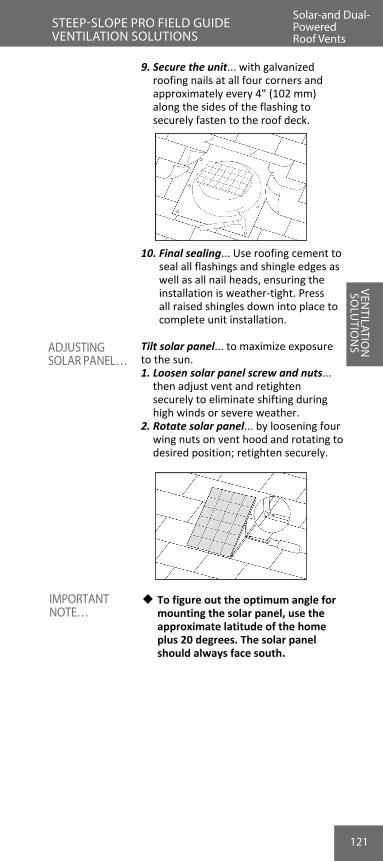
121
ADJUSTING SOLAR PANEL…
IMPORTANT NOTE…
9. Secure the unit... with galvanized roofing nails at all four corners and approximately every 4" (102 mm) along the sides of the flashing to securely fasten to the roof deck.
10. Final sealing... Use roofing cement to seal all flashings and shingle edges as well as all nail heads, ensuring the installation is weather-tight. Press all raised shingles down into place to complete unit installation.
Tilt solar panel... to maximize exposure to the sun.1. Loosen solar panel screw and nuts...
then adjust vent and retighten securely to eliminate shifting during high winds or severe weather.
2. Rotate solar panel... by loosening four wing nuts on vent hood and rotating to desired position; retighten securely.
w To figure out the optimum angle for mounting the solar panel, use the approximate latitude of the home plus 20 degrees. The solar panel should always face south.
VENTILATIO
N
SOLU
TION
SSTEEP-SLOPE PRO FIELD GUIDE VENTILATION SOLUTIONS
Solar-and Dual-Powered Roof Vents
122
VEN
TILA
TIO
N
SOLU
TIO
NS
Exhaust Ventilation Louvers… • Easy to install • Perfect for tough-to-vent roofs • Wide variety of sizes, airflow, and
styles
Note: Roof louvers are also commonly called “mushroom vents,” “soldier vents,” “airhawks,” “cake pans,” and “box vents.”
Master Flow® Roof Louvers come in different styles (Slant Back or Square Top) and are available in both plastic and aluminum construction.
Ventilation Yields Vary…The following are the ventilation yields available… 37 sq. in. (23,872 sq. mm), 50 sq. in.(32,260 sq. mm), 60 sq. in. (38,712 sq. mm), and 65 sq. in. (41,938 sq. mm)
1. Calculate number of louvers needed… use FHA/HUD guide lines on page 87-90. • Space vents evenly… along back of
roof and between rafters. • Locate properly near ridge…
Ensure they are close to, but below, the ridge line.
2. Cut hole in roof… Size of opening depends on roof louver selection.
3. Measure and roll back shingles… • Roll shingles and remove all nails
in area where flashing will be around the hole.
w To increase weather protection... install an 18" x 18" (457 x 457 mm) piece of GAF Leak Barrier around the hole.
• Remove release film and center Leak Barrier over hole.
• Press into place and cut Leak Barrier spanning the hole.
4. Position roof louver… Center over hole to create maximum airflow.
5. Mount roof louver… Use nails to secure in place.
6. Reapply shingles… Press shingles back into place for a weather-tight seal.
7. Seal shingles… and all exposed flashing edges and nail heads with plastic roof cement to ensure a weather-tight seal.
Note: Do not use excess roof cement on aluminum roof louvers. It may cause blistering of the roofing shingles.
THE BENEFITS OF ROOF EXHAUST LOUVERS…
A COMPLETE LINE OF MASTER FLOW® ROOF LOUVERS…
INSTALLING ROOF LOUVERS…
IMPORTANT NOTE…
Static Roof Louver
STEEP-SLOPE PRO FIELD GUIDE VENTILATION SOLUTIONS

123
VEN
TILA
TIO
NSO
LUTI
ON
S
1. Required opening size for each louver… • SSB960A… 10" (254 mm) (Round) • IR65… 12" x 11" (305 x 279 mm)
(Rectangle) • IR61… 10" x 10" (254 x 254 mm)
(Square) • RT65… 11" x 10" (279 x 254 mm)
(Rectangle) • R504/R50A… 9" (229 mm) (Square)2. Do not use petroleum-based substances
such as roof cement with plastic roof louvers… as these materials may damage plastic louvers.
VENTILATIO
N
SOLU
TION
S
ROOF LOUVER GUIDE LINES…
Static Roof Louver
STEEP-SLOPE PRO FIELD GUIDE VENTILATION SOLUTIONS
CUT HOLE IN ROOF*
MEASURE & ROLL SHINGLES*
POSITION & MOUNT ROOF LOUVER…
* Installation shown is for a SSB960 Roof Louver. See indi-vidual product packaging for information on and installa-tion instructions for other Master Flow® Roof Louvers.
Static Roof Louver

124
For added exhaust ventilation… • Move large quantities of air. • Use wind to create convection.
Dual-bearing construction for long-lasting performance… • Two-piece design for easy
installation. • Lifetime limited warranty* on all
turbine units.* See Master Flow® Powered Ventilation
Products Ltd. Warranty for complete coverage and restrictions.
1. Cut hole in roof… between two rafters and through shingles and sheathing boards.
• Cut hole to 12" (305 mm) diameter for a 12" (305 mm) turbine.
• Cut hole to 14" (356 mm) diameter for a 14" (356 mm) turbine.
2. Measure and mark 5 ½" (140 mm) from each direction of hole… Provides area to roll back shingles (do not measure from bottom of hole).
3. Prepare hole… Roll back all shingles within marks, and remove all nails.
4. Adjust turbine base… aligning stack to a vertical position to reduce the effects of weather.
w To increase weather protection...install an 18" x 18" (457 x 457 mm) piece of GAF Leak Barrier around the hole.
• Remove release film and center Leak Barrier over hole.
• Press into place and cut Leak Barrier spanning the hole.
5. Mount base… Center over hole and underneath removed shingles using caulk and nails.
6. Press shingles back in place… to roof and over flashing to create a weather-tight seal.
7. Mount turbine to base… Use 3 sheet metal screws for extra stability.
8. Seal shingles with plastic cement… Seal all seams, flashing edges, and exposed nail heads to reduce the effects of weather.
9. Seal turbine with silicone caulk… Seal seams on turbine with silicone caulking.
Note: When severe weather is expected, be sure to install a Master Flow® Turbine Weather Cap.
IMPORTANT NOTE…
THE BENEFITS OF TURBINE VENTS…
INSTALLING A TURBINE VENT…
THE BENEFITS OF DUAL- BEARING TURBINE VENTS…
Turbine VentsSTEEP-SLOPE PRO FIELD GUIDE VENTILATION SOLUTIONS
VEN
TILA
TIO
N
SOLU
TIO
NS

125
VEN
TILA
TIO
N
SOLU
TIO
NS
MEASURE & ROLL SHINGLES*
CUT HOLE
ADJUST
* Instructions represent a 14" (356 mm) turbine installation.
VENTILATIO
NSO
LUTIO
NS
Turbine VentsSTEEP-SLOPE PRO FIELD GUIDE VENTILATION SOLUTIONSTurbine Vents

126126
Best use… to quickly remove overheated air from homes into attics. Whole House Fans bring cool fresh air into the home from outside. Whole House Fans with intake ventilation can help reduce attic mold and mildew.
Helps reduce utility costs… homeowners are adding Whole House Fans as a way to reduce their AC costs.• Leave the AC off during the day.• Come home and turn on whole
house fan.• Remove super-heated air—turn on
AC.
Pulls cool fresh air in... drives hot air out.• Helps Promote Energy Efficiency…
Where cooling costs are a concern.• Two-Speed Pull Chain Operation…
Eliminates switch wiring.
Always use with properly balanced attic ventilation (intake & exhaust)... While Whole House Fans work best in conjunction with a properly ventilated attic, they do NOT replace proper attic ventilation, and they do not replace intake ventilation.
Available in 24" (610 mm) Direct Drive style and 30" (762 mm) Belt Drive style.
Installing A Whole House Fan:• Qualified to work with electricity?
If you are not very experienced at installing residential electrical wiring or are not familiar with national or local electrical codes, contact a qualified electrician to complete installation.
• Electrical power supply... The fan should be connected to a circuit with the correct power to safely operate the fan and prevent damage to the motor using minimum 14-gauge wiring. The circuit must have at least 5 amperes of available capacity. If you cannot confirm that there is enough electrical capacity on an existing circuit, a separate dedicated circuit should be installed.
• Enough attic space... This Whole House Fan should be installed in attics with at least 500 square feet (46.4 m2) of area.
THE BENEFITS OF MASTER FLOW® WHOLE HOUSE FANS…
KEY CONSIDERATIONS…
Whole House Fans
STEEP-SLOPE PRO FIELD GUIDE VENTILATION SOLUTIONS
VEN
TILA
TIO
N
SOLU
TIO
NS
127
VEN
TILA
TIO
N
SOLU
TIO
NS
INSTALLING A WHOLE HOUSE FAN – NO JOIST-CUT INSTALLATION…
VENTILATIO
N
SOLU
TION
SWhole House Fans
STEEP-SLOPE PRO FIELD GUIDE VENTILATION SOLUTIONS
• A working attic ventilation system... with both intake and exhaust ventilation allows heated air to be exhausted by the Whole House Fan and forced to exit the attic.
1. Determine location… Select a central hallway (upstairs, if applicable, to ensure optimum airflow).
2. Measure clearance above fan… A minimum of 30" (762 mm) of clearance is needed above the fan in the attic for proper air movement.
3. Measure the hallway… to ensure proper fit of shutter.
a. Joists perpendicular to hallway… Hallway must be:
• 30" (762 mm) wide for a 24" (610 mm) fan.
• 36" (914 mm) wide for a 30" (762 mm) fan.
b. Joists parallel with hallway… Must have 15 ½" (394 mm) from the center of the joist to the wall or ceiling molding for a 24" (610 mm) or 30" (762 mm) fan.
4. Remove insulation in area above fan.5. Locate joist… nearest the center of
preselected fan location.6. Cut shutter opening… Sized to fit
shutter, not fan — use template on shutter carton.
7. Lift fan into attic… to begin mounting process.
8. Attach brackets… to wood frame using bolts provided.
9. Place fan… Set fan on joist, centered over hole.
10. Secure fan… from hallway by drilling holes in joist through joist bracket and using the 2" (51 mm) S bolts provided.
11. Enclose fan… using plenum boards provided with screws and duct tape.
12. Replace insulation… around fan perimeter.
13. Adjust motor position… only on belt drive units to ensure proper belt tension.
14. Wire unit… adhering to all local codes.15. Install the shutter… from hallway, using
mounting screws provided.
Note: Use a licensed, qualified electrician to wire the unit into place to ensure your safety and meet applicable electrical and building codes.
Whole House Fans

128
NO JOIST-CUT ILLUSTRATIONS…
1. Measure Clearance 2. Locate Joist and Cut Shutter Opening
3. Lift Fan Into Attic 4. Attach Brackets
5. Place Fan 6. Secure Fan
7. Enclose Fan
Whole House Fans
STEEP-SLOPE PRO FIELD GUIDE VENTILATION SOLUTIONS
DESIRED FAN LOCATION
VEN
TILA
TIO
N
SOLU
TIO
NS
Step 1: Measure Clearance Step 2: Locate Joist and Cut Shutter Opening
Step 4: Attach Brackets
Step 6: Secure Fan
Step 3: Lift Fan into Attic
Step 5: Place Fan
Step 7: Enclose Fan

129
VEN
TILA
TIO
N
SOLU
TIO
NS
1. Determine location… Select a central hallway (upstairs, if applicable, to ensure optimum airflow).
2. Measure clearance above fan… at least 30" (762 mm) of clearance is needed above the fan in the attic for proper air movement.
3. Measure the hallway… to ensure proper fit of shutter.
a. Joists perpendicular to hallway… Hallway must be:
• 30" (762 mm) wide for a 24" (610 mm) fan.
• 36" (914 mm) wide for a 30" (762 mm) fan.
b. Joists parallel with hallway… Must have 15 ½" (394 mm) from the center of the joist to the wall or ceiling molding for a 24" (610 mm) or 30" (762 mm) fan.
4. Remove insulation above fan area.5. Begin at joist… and extend opening
as required.6. Cut sheetrock… inside shutter
dimensions provided on shutter carton template.
7. Frame opening… between joists and at the sides with joist-sized lumber.
8. Lift fan into attic.9. Build platform… along top of frame
using at least 1" x 4" (25 x 102 mm) lumber.
10. Create duct from living space… extended platform wide enough to support all edges of the fan frame.
11. Cut joists… across opening, flush with framing.
12. Place fan on platform… secure with nails and L brackets.
13. Replace insulation.14. Adjust motor position… only on belt
drive units to ensure proper belt tension.
15. Wire unit… adhering to all local codes.16. Install the shutter… from hallway,
using mounting screws provided.
Note: Use a licensed, qualified electrician to wire the unit into place to ensure your safety and meet applicable electrical and building codes.
INSTALLING A WHOLE HOUSE FAN – JOIST-CUT INSTALLATION…
VENTILATIO
N
SOLU
TION
SWhole House Fans
STEEP-SLOPE PRO FIELD GUIDE VENTILATION SOLUTIONS
Whole House Fans
129

130130
ROO
FIN
G
BASI
CSWhole House Fans
STEEP-SLOPE PRO FIELD GUIDE VENTILATION SOLUTIONS
JOIST-CUT ILLUSTRATIONS…
Step 1: Measure Clearance Step 2: Cut Shutter
Step 3: Frame Opening Step 4: Lift Fan Into Attic
Step 5: Build Platform Step 6: Secure Fan On & Cut Joist Platform
DESIRED FAN LOCATION
JOIST TO BE CUT
FRONT END FRAME PIECE
REAR END FRAME PIECE
SIDE FRAME PIECES
PLATFORM
VEN
TILA
TIO
N
SOLU
TIO
NS

VEN
TILA
TIO
N
SOLU
TIO
NS
131
ROO
FING
BA
SICSVEN
TILATION
SO
LUTIO
NS
Whole House Fans NOTES

132
Best used to pull heated air out of attics, cooling them quickly.• Minimizes heat and moisture
damage in your attic.• Increases overall comfort of your home
by exhausting hot air out of your attic quickly.
1. Determine location… Mount behind a current wall louver or install a Master Flow® SGM20 Automatic Gable Louver.
2. Attach mounting brackets to power vent… using bolts and nuts provided.
3. 16" (406 mm) center studs... mounting brackets are predrilled to this size.
4. Over 16" (406 mm) centers… box the ventilator with 2" x 4" (51 x 102 mm), 14" (356 mm) apart, above and below unit.
5. Mount the unit… On 16" (406 mm) centers, mount to existing studs; over 16" (406 mm) centers, mount the unit to horizontal framing.
6. Install the thermostat*… make sure the conduit is somewhat slack and the element is not covered.
7. Wire the thermostat*… following all local codes — use an electrician when appropriate.
8. Adjust fan control… Set at 105°F (40.6°C) for maximum energy savings.
*If the unit has a humidistat/thermostat.
Power Gable Vents
STEEP-SLOPE PRO FIELD GUIDE VENTILATION SOLUTIONS
THE BENEFITS OF POWER GABLE VENTS…
INSTALLING A MASTER FLOW®
POWER GABLE VENT…
VENTILATIO
N
SOLU
TION
S
VEN
TILA
TIO
N
SOLU
TIO
NS

133
VEN
TILA
TIO
N
SOLU
TIO
NS
Solar and Dual Powered Gable Vent
STEEP-SLOPE PRO FIELD GUIDE VENTILATION SOLUTIONS
Easy installations… No extra wiring or expensive electricians required to install.
Note: See Master Flow® Powered Ventilation Products Ltd. Warranty for complete coverage and restrictions.
Installing A Solar-Powered Gable Vent1. Determine the location… Mount
vent 3"-4" (76-102 mm) behind existing gable wall louver or install a Master Flow® Gable Louver to allow proper air flow.
2. Attach mounting brackets to unit... using nuts and bolts provided. Fasten securely using predrilled holes in unit shroud to eliminate vibration.
3. Place mounting brackets... so that end of bracket is flush with stud.
• For 16" (406 mm) on-center studs, mounting brackets are predrilled to this size. Screw or nail the unit to the framing through predrilled holes in brackets for proper placement.
THE BENEFITS OF MASTER FLOW® GREEN MACHINE™ SOLAR-POWERED GABLE VENT…
INSTALLING THE UNIT…
Power Gable Vents
VENTILATIO
N
SOLU
TION
S

134
Solar and Dual Powered Gable Vent
STEEP-SLOPE PRO FIELD GUIDE VENTILATION SOLUTIONS
• For studs over 16" (406 mm) on-center, install two 2" x 4" (51 x 102 mm) supports 14" (356 mm) apart above and below the unit to existing horizontal framing for proper placement.
4. Mount to supports... through the predrilled holes in the mounting brackets.
5. Determine location of panel... Locate solar panel on part of the roof as close to the gable fan as possible to make sure included 10' (3.05 m) power cord reaches the panel.
w Always attempt to have unit face south for optimal power. Make sure it is not shaded by trees or other nearby structures during the day.
Included solar panel connecting wire is 10' (3.05 m) long. Be sure location is within this distance.
6. Mount solar panel… • Place the solar panel in the desired
location, making sure that the top rails extend at least 1 ½" (38 mm) above shingle course overlap. Align the “L”-shaped wings making sure that the bolt hole in each “L”-shaped wing is in the center of the short slot in the rail. Use a grease pencil or chalk to trace the outline of the “L”-shaped wings on the shingle. Note: To avoid possible weather infiltration, do not place the “L”-shaped wings or the top rails on the vertical spaces between the shingle tabs.
• Remove the “L”-shaped wings from the shingles and lay the solar panel aside. At the location traced above, carefully pry up the shingles and slide each “L”-shaped wing under a shingle and align each wing with a deck screw. Release and press shingle into place. Apply roofing cement under the shingles to secure them to the roof.
IMPORTANT NOTE…
MOUNT THE SOLAR PANEL…
VENTILATIO
N
SOLU
TION
S
VEN
TILA
TIO
N
SOLU
TIO
NS

135
VEN
TILA
TIO
N
SOLU
TIO
NS
STEEP-SLOPE PRO FIELD GUIDE VENTILATION SOLUTIONS
• Carefully pry up the shingles where the top rails will attach. Determine this location by aligning the solar panel frame between the installed “L”-shaped wings and centering the short slots in the rails with the mounting holes in the “L”-shaped wings. Slide the top rails under raised shingles and attach each rail to the roof deck with a deck screw. Release and press the shingles into place. Apply roofing cement under the shingles to secure them to the roof.
• Finish by attaching the “L”-shaped wings to the rails with the bolts and nuts provided and tighten them securely. Run included wire from solar panel to the gable fan through an open slot in the exterior louver. Be sure to route the wire around the gable fan housing.
7. Adjust... to maximize exposure to the sun. • To tilt solar panel, loosen screws/nuts,
adjust panel, and retighten fasteners securely so that the panel cannot shift out of position.
• To rotate solar panel, loosen four wing nuts on vent hood and rotate to desired position. Retighten securely.
w To figure out the optimum angle for mounting the solar panel, use the approximate latitude of the house plus 20 degrees. The solar panel should face south for maximum power.
8. Run included 10' (3.05 m) wire to solar panel... Run connecting wire out exterior wall louver to previously mounted solar panel to make connection.
9. Attach wire to solar panel... • (RED) positive lead from connecting
wire to (RED) positive lead of solar panel.
• (BLACK) negative lead from connecting wire to the (BLACK) negative lead from solar panel to complete installation.
Caution: Control
board has sensitive electronic components.
ADJUSTING SOLAR PANEL…
IMPORTANT NOTE…
VENTILATIO
N
SOLU
TION
SSolar and Dual Powered Gable Vent

136
REVIEW #9STEEP-SLOPE PRO FIELD GUIDE
1. True or False? Continuous ridge vents along with continuous soffit/fascia vents offer the best attic ventilation system.
A. True B. False
2. What is the best way to ventilate a soffit? A. Round pop-in vents. B. With rectangular louvers. C. Through the gable ends. D. With continuous soffit vents.
3. When installing ridge vents, how much uncut sheathing should be left at the gable ends to prevent wind-driven rain from entering the structure?
A. 0" (0 mm). B. 2 ½" (64 mm). C. 6" (152 mm). D. 18" (457 mm).
4. When installing Cobra® Rigid Vent 3™ or Cobra® Snow Country™ Exhaust Vents on a ridge without a ridge board, what is the overall opening size width?
A. 3" (76 mm). B. 6" (152 mm). C. 2" (51 mm). D. 11" (279 mm).
5. True or False? Whole House Fans in conjunction with properly balanced attic ventilation can help reduce attic mold and mildew.
A. True B. False
VEN
TILA
TIO
N
SOLU
TIO
NS
137
ROO
FING
BA
SICSPre-Shingling Checklist
STEEP-SLOPE PRO FIELD GUIDE GENERAL FASTENING AND WIND RESISTANCE
Check these before shingles are installed…1. Have you verified the contract with
the homeowner? • Correct shingle type? • Correct shingle color? • Correct finishes and details?2. Is the job site safe? • Ladders and scaffolds secure? • Site well organized and safe? • Homeowner aware of hazardous
areas? • Material properly stored? • Fall protection in place if needed?3. Is the deck dry and flat?4. The underlayments… • GAF Leak Barrier properly installed? • Deck-Armor™ or other GAF
Roof Deck Protection lying flat, unbuckled?
5. Is the drip edge properly installed… • Metal flush to the deck? • Roof Deck Protection over at eaves,
under at the rake edge?
MAKE SURE YOU ARE READY TO SHINGLE…
REVIEW #9FASTENING & W
IND RESISTANCE

138138
ROO
FIN
G
BASI
CS
1. The back… start all projects on the least visible area, to work out any unusual details.
2. Don’t “corner” your team… Roofers work fastest reaching across their bodies.
• Left-handed roofers are faster starting on their right.
• Right-handed roofers are faster starting on their left.
3. Work toward the difficult areas… • Don’t start in valleys, etc.
Roofing nails…1. Corrosion resistant… Zinc coated,
steel, or aluminum for corrosion resistance.
2. Nail shank… 10 to 12-gauge barbed, smooth, or deformed shank for grip-ping deck.
3. Holding capacity… Nail heads of 3/8" (10 mm) to 7/16" (11 mm) in diameter to hold shingles in wind.
4. Fastener should be long enough… • To penetrate 3/4" (19 mm) into
wood plank decks. • Penetrate through plywood or OSB
decks.
w GAF, in accordance with ARMA… does not recommend the use of staples as fasteners for shingles.
• Flush with shingle surface• Driven straight
WHERE DO YOU START TO SHINGLE?
FASTENERS...
MONACO
® SHINGLES
FAST
ENIN
G & W
IND
RESIS
TANC
EGeneral Fastening Tips
STEEP-SLOPE PRO FIELD GUIDE GENERAL FASTENING AND WIND RESISTANCE
FASTENING & WIND
RESISTANCE

139
ROO
FING
BA
SICS
1. Overdriving fasteners… • Damages the shingles… Over-
driving can drive fasteners right through the shingle.
• Shingles slip off the roof… when overdriven fasteners go through a shingle, these shingles are barely held onto the roof. Over time they can slide off the roof deck.
• From too much pressure… over-driving most often occurs when a nail gun is set to the wrong pres-sure.
2. Underdriving fasteners… • Nail-pop… fasteners that are not
driven flush to the shingle can “pop” up with deck movement.
• Nail-popping lifts the shingle… pulling the shingle away from the self-sealant.
• Shingles then blow off… when lifted up from the sealant, shingles are set up into the wind, causing shingle blow-offs.
• Cuts through shingle face… under-driven fasteners can create holes when the shingle above settles over the popped up nail.
3. Nails that are driven at an angle… • Will cut shingles… angled fasteners
will cut through overlying shingles. • Are not fully anchored to the
deck… angled fasteners are subject to backing out with deck move-ment because they are not fully driven into a deck.
FASTENERS MUST BE DRIVEN PROPERLY…
General Fastening Tips
STEEP-SLOPE PRO FIELD GUIDE GENERAL FASTENING AND WIND RESISTANCE
General Fastening Tips
FASTENING & WIND
RESISTANCE

140140
GAF’s Dura Grip™ Adhesive is one of the strongest shingle sealants available.• Seals itself… this sealant is designed
to seal shingles together after being installed.
• Sealant works with the sun… sun and warm temperatures activate the seal-ant and bond the shingles together.
The weather…1. If installed in cold weather… sealant
may not seal until the following spring.2. When the sealant gets contaminated
with dirt… • Wind-blown dust or sand…
can coat the sealant and keep it from sealing.
3. Blow-offs and damage before sealing…
• When blow-offs occur before the thermal sealing can take place, it is not a shingle defect.
Mansards and Steep-Slopes… slopes greater than 21:12…1. Shingles need to rest on the sealant… • On Steep-Slopes and mansards, the
shingle’s full weight is not on the sealant.
• These shingles may not seal prop-erly.
2. Hand-seal these shingles… apply quarter-sized dabs of roofing cement to seal these shingles.*
3. Six nails… the installation of 6 nails per shingle on standard size shingles is not required by GAF, but is required by some local building codes and is re-quired for enhanced wind coverage on certain products. See limited warranty for details.
• See pages 141-142 “How to Hand-Seal...” for application.
w Not for vertical walls… do NOT install shingles on vertical surfaces.
Hand-sealing shingles on mansards and roofs with slopes greater than 21:12 is required for Weather Stop-per® Golden Pledge® and Silver Pledge® Installations.
GAF DURA GRIP™ ADHESIVE
WHAT INTERFERES WITH PROPER SEALING…
SEALING MANSARDS AND STEEP-SLOPES…
WEATHER STOPPER® GOLDEN PLEDGE® AND SILVER PLEDGE® NOTE
MONACO
® SHINGLES
FAST
ENIN
G & W
IND
RESIS
TANC
EEnsuring Wind Resistance
STEEP-SLOPE PRO FIELD GUIDE GENERAL FASTENING AND WIND RESISTANCE
FASTENING & WIND
RESISTANCE

141
Hand-seal when installing… • In cold weather, fall, or winter. • On roofs with slopes greater than
21:12. • If self-sealant gets dirty. • In areas where airborne dust or
sand can be expected before seal-ing occurs.
1. Use a quarter-sized dab of roofing ce-ment… to properly seal these shingles.
• Too much cement can run down the shingle face, or cause blister-ing.
2. Apply dabs of roofing cement… to each shingle.
• Four dabs on Timberline® Series Shingles and Glenwood® Shingles.
• Two dabs per tab on Sovereign™ Series, Grand Canyon®, Grand Sequoia®, and Slateline®.
• Eight dabs on Woodland® and Camelot® Series Shingles.
• Three dabs per diamond tab on Sienna® Shingles.
3. Press shingle into cement... to fully seal these shingles.
Sovereign™ Series Shingles
Timberline® Series Shingles
Grand Canyon®/ Grand Sequoia® Series
HOW TO HAND-SEAL…
HAND-SEAL SHINGLES FOR IMMEDIATE SEALING AND ON STEEP-SLOPES…
Hand-Sealing Shingles And Steep- Slope Precautions
STEEP-SLOPE PRO FIELD GUIDE GENERAL FASTENING AND WIND RESISTANCE
WHEN TO HAND-SEAL SHINGLES…
Ensuring Wind Resistance
FASTENING & WIND
RESISTANCE

142
Woodland® Shingles
Sienna® Shingles
Camelot® Series Shingles
Slateline® Shingles
Glenwood™ Shingles
142
HAND-SEAL SHINGLES FOR IMMEDIATE SEALING AND ON STEEP-SLOPES…(continued)
MONACO
® SHINGLES
FAST
ENIN
G & W
IND
RESIS
TANC
EHand-Sealing Shingles and Steep- Slope Precautions
STEEP-SLOPE PRO FIELD GUIDE GENERAL FASTENING AND WIND RESISTANCE
FASTENING & WIND
RESISTANCE
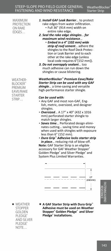
143
ROO
FING
BA
SICS
WeatherBlocker™ Premium Eave/Rake Starter Strip can be used with any GAF shingle… a time-saving and versatile high-performance starter shingle.
Can be used with:• Any GAF and most non-GAF, Eng-
lish, metric, oversized, and designer shingles.
• Oversized… A 17" x 40" (432 x 1016 mm) perforated starter shingle to match larger shingles.
• Saves time… Perforated design elimi-nates cutting… saving time and money when used with shingles with exposure less than 6" (152 mm).
• Dura Grip™ Adhesive locks starter strip in place… reducing risk of blow-off.
Note: GAF Starter Strip is an eligible accessory for GAF Weather Stopper® Golden Pledge® and Silver Pledge® and System Plus Limited Warranties.
A GAF Starter Strip with Dura Grip™ Adhesive must be used on Weather Stopper® Golden Pledge® and Silver Pledge® installations.
WeatherBlocker™ Starter Strip
STEEP-SLOPE PRO FIELD GUIDE GENERAL FASTENING AND WIND RESISTANCE
WEATHER- BLOCKER™
PREMIUM EAVE/RAKE STARTER STRIP…
WEATHER STOPPER GOLDEN PLEDGE® AND SILVER PLEDGE® NOTE…
Hand-Sealing Shingles and Steep- Slope Precautions
MAXIMUM PROTECTION ON RAKE EDGES…
1. Install GAF Leak Barrier… to protect rake edges from water infiltration.
• Full 36" (914 mm) width on entire rake edge.
2. Seal the rake edge shingles… for maximum wind resistance…
• Embed in a 4" (102 mm) wide strip of roof cement… adhere the shingles to the Roof Deck Protec-tion or Leak Barrier and to each other at the rake edge (unless local code requires 6"[152 mm]).
3. Do not overapply sealant… too much adhesive can run down the shingles or cause blistering.
FASTENING & WIND
RESISTANCE
144144
Installing WeatherBlocker™ Premium Eave/Rake Starter Strip…
1. Perforated design… Perforated to save time and costs associated with wasted materials.
2. Install from either end of roof… WeatherBlocker™ Starter Strip can be installed from right to left, or left to right.
3. Position with sealant up… Place the starter strip with the sealant facing up at the eave edge. For standard ap-plication, position the starter strip so the sealant line is at the edge.
Note: Some shingles require a special installation positioning for Weather-Blocker™ Starter Strip as denoted in those shingle installation instructions.4. Provide 1/4"- 3/4" (6-19 mm) drip
edge… Place starter shingles 1/4"-3/4" (6-19 mm) over eave and rake edges to provide drip edge.
5. Fastening… Nail approximately 11/2"-3" (38-76 mm) above butt edge of shingle and approximately 1"-2" (25-51 mm) and 10"-12" (254-305 mm) in from each side edge. Fasten with at least 4 nails per shingle.
6. Rake installation… position starter strip so that it overlaps the eave edge starter by at least 3" (76 mm) with sealant facing rake edge. Fasten with at least 4 nails per shingle
• Fastening... nail vertically along a line 1 1/2"-3" (38-76 mm) in from the rake edge.
7. Start shingles from same side… Starter shingles and roof shingles should start from the same side.
8. For maximum wind resistance… • Along rakes, install any GAF starter
strip containing sealant or cement shingles to roof deck protection and/or leak barrier and drip edge with a 4" (102 mm) wide strip of plastic roof cement [unless local code requires 6" (152 mm) wide].
A GAF Starter Strip with Dura Grip™ Adhesive must be installed on Weather Stopper® Golden Pledge® and Silver Pledge® Installations.
INSTALLING WEATHER- BLOCKER™ PREMIUM EAVE/RAKE STARTER STRIP GENERAL APPLICATION…
WEATHER STOPPER® GOLDEN PLEDGE® AND SILVER PLEDGE® NOTE…
MONACO
® SHINGLES
FAST
ENIN
G & W
IND
RESIS
TANC
ESTEEP-SLOPE PRO FIELD GUIDE GENERAL FASTENING AND WIND RESISTANCE
WeatherBlocker™ Starter Strip
FASTENING & WIND
RESISTANCE

145
When used at eave with shingles with exposures of at least 6" (152 mm)… • Always use a full 17" (432 mm)
height shingle pieces… Do NOT separate the WeatherBlocker™ Starter Strip into halves.
• Cut a 10" (254 mm) length of WeatherBlocker Starter Strip and install as first piece. Fasten with 2 nails… then continue with full pieces across the eave.*
• Fasten with at least 4 nails per shingle
• Coverage… 50 lineal feet (15.24 lm) per bundle.
For installation along rakes: • Separate WeatherBlocker™ starter
strips into half pieces, 8 1/2" x 40" (216 x 1016 mm).
• Position the starter strip so that it overlaps the eave edge starter strip at least 3" (76 mm).
• Nail vertically along a line 1 1/2" to 3" (38-76 mm) in from the rake edge. Fasten with at least 4 nails per shingle.
• Place the first nail 1/2"- 1 1/2" (13-38 mm) from the bottom edge of the starter strip and every 10"-12" (354-305 mm) up the rake.
* For all applications, the butt joints of the WeatherBlocker™ Starter Strip must be offset from the butt joints of the first course of shingles by 4" (102 mm) or more. For long eaves, a 10"-12" (254-305 mm) piece of WeatherBlocker™ Starter Strip may need to be installed periodically to adjust the offset. The frequency of this adjustment will depend on the length of the shingle being installed.
ROO
FING
BA
SICS
INSTALLING WEATHER- BLOCKER™ PREMIUM EAVE/RAKE STARTER STRIP WITH SHINGLES HAVING 6" (152 MM) OR GREATER EXPOSURE…
WeatherBlocker™ Starter Strip
STEEP-SLOPE PRO FIELD GUIDE GENERAL FASTENING AND WIND RESISTANCE
WeatherBlocker™ Starter Strip
FASTENING & WIND
RESISTANCE

146146
When used at eave with shingles with exposures less than 6" (152 mm)… • Always separate WeatherBlocker™
Starter Strips into 8 1/2" (216 mm) height, half pieces.
• Cut a 10" (254 mm) length of WeatherBlocker™ Starter Strip and in-stall as first piece. Fasten with 2 nails… then continue with full length pieces across the eave.*
• Fasten with at least 4 nails per shingle.
• Coverage… 100 lineal feet (30.48 lm) per bundle.
For installation along rakes:• Position the starter strip so that it
overlaps the eave edge starter strip at least 3" (76 mm).
• Nail vertically along a line 1 1/2"-3" (38-76 mm) in from the rake edge.
• Fasten with at least 4 nails per shingle.• Place the first nail 1/2"- 11/2" (13-38 mm)
from the bottom edge of the starter strip and every 10"-12" (354-305 mm) up the rake.
* For all applications, the butt joints of the WeatherBlocker™ Starter Strip must be offset from the butt joints of the first course of shingles by 4" (102 mm) or more. For long eaves, a 10"-12" (254-305 mm) piece of WeatherBlocker™ Starter Strip may need to be installed periodically to adjust the offset. The frequency of this adjustment will de-pend on the length of the shingle being installed.
INSTALLING WEATHER- BLOCKER™ PREMIUM EAVE/RAKE STARTER STRIP WITH SHINGLES HAVING LESS THAN 6" (152 MM) EXPOSURE…
MONACO
® SHINGLES
FAST
ENIN
G & W
IND
RESIS
TANC
ESTEEP-SLOPE PRO FIELD GUIDE GENERAL FASTENING AND WIND RESISTANCE
WeatherBlocker™ Starter Strip
FASTENING & WIND
RESISTANCE

147
Pro-Start® Starter Strip can be used with...shingles with an exposure up to 6" (152 mm).• Size… 13" x 38" (330 x 965 mm)
perforated starter shingle.• Saves time… Perforated design
eliminates cutting… saving time and money.
• Dura Grip™ Adhesive locks starter strip in place… reducing risk of blow-off.
Note: GAF Starter Street is an eligible accessory for GAF Weather Stopper® Golden Pledge® and Silver Pledge® and System Plus Limited Warranties.
A GAF Starter Strip with Dura Grip™ Adhesive must be installed on Weather Stopper® Golden Pledge® and Silver Pledge® Installations.
Installation… only with shingle exposures up to 6" (152 mm). • Separate into half pieces…
6 1/2" x 38" (165 x 965 mm). • Coverage… 33 lineal feet (10 lm)
per bundle.
For shingles with English dimensions12" x 36" (305 x 914 mm)… • Cut a 10" (254 mm) length of
Pro-Start® Starter Strip and install as first piece… then continue with full-length pieces across the eave (see note next page).
PRO-START®
EAVE/RAKE STARTER STRIP…
Pro-Start® Starter Strip
STEEP-SLOPE PRO FIELD GUIDE GENERAL FASTENING AND WIND RESISTANCE
WEATHER STOPPER® GOLDEN PLEDGE® AND SILVER PLEDGE® NOTE…
INSTALLING PRO-START® EAVE/RAKE STARTER STRIP…
WeatherBlocker™ Starter Strip
FASTENING & WIND
RESISTANCE

148148
ROO
FIN
G
BASI
CS
MONACO
® SHINGLES
FAST
ENIN
G & W
IND
RESIS
TANC
ESTEEP-SLOPE PRO FIELD GUIDE GENERAL FASTENING AND WIND RESISTANCE
Pro-Start® Starter Strip
For shingles with metric dimensions13 1/4" x 39 3/8" (337 X 1000 mm)… • Trim 3"(76 mm) from the first piece
installed and continue with full pieces across the eave.
Note: For all applications, the butt joints of the Pro-Start® Starter must be offset from the butt joints of the first course of shingles by 4" (102 mm) or more. For long eaves, a 10-12" (254- 305 mm) piece of Pro-Start® Starter Strip may need to be installed periodically to adjust the offset. The frequency of this adjustment will depend on the length of the shingle being installed.
Installing Pro-Start® Eave/Rake Starter Strip…1. Perforated design… Perforated to save
time and costs associated with wasted materials.
2. Install from either end of roof… Pro-Start® Starter Strip can be installed from right to left, or left to right.
3. Position with sealant up… Place the starter strip with the sealant facing up at the eave edge. Position the starter so the sealant line is at the edge.
4. Provide 1/4"-3/4" (6-19 mm) drip edge… Place starter shingles 1/4"-3/4" (6-19 mm) over eave and rake edges to provide drip edge.
5. Fastening… Nail approximately 1 ½"-3" (38-76 mm) above butt edge of shingle and approximately ½"-1 ½" (13-38 mm) and 10"-12" (254-305 mm) in from each side edge.
• Fasten with at least 4 nails per shingle.
6. Start shingles from same side… Starter shingles and roof shingles should start from the same side.
7. For maximum wind resistance… along rakes, install any GAF starter strip containing sealant or cement shingles to underlayment and each other in a 4" (102 mm) width of asphalt plastic roof cement.
INSTALLING PRO-START®
EAVE/RAKE STARTER STRIP GENERAL APPLICATION…
FASTENING & WIND
RESISTANCE

149
ROO
FING
BA
SICSSTEEP-SLOPE PRO FIELD GUIDE GENERAL FASTENING AND WIND RESISTANCE
Pro-Start® Starter Strip
For installation along rakes: • Position the starter strip so that it
overlaps the eave edge starter strip at least 3"(76 mm).
• Nail vertically along a line 1 1/2" to 3" (38-76 mm) in from the rake edge.
• Place the first nail 1/2"- 1 1/2"(13-38 mm) from the bottom edge of the starter strip and every 10"-12"(354-305 mm) up the rake.
• Fasten with at least 4 nails per shingle.
Note: For all applications, the butt joints of the Pro-Start® Starter Strip must be offset from the butt joints of the first course of shingles by 4" (102 mm) or more. For long eaves, a 10-12" (254- 305 mm) piece of Pro-Start® Starter Strip may need to be installed periodically to adjust the offset. The frequency of this adjustment will depend on the length of the shingle being installed.
Pro-Start® Starter Strip
FASTENING & WIND
RESISTANCE

150150
MONACO
® SHINGLES
FAST
ENIN
G & W
IND
RESIS
TANC
E
1. What can happen when a fastener is overdriven? A. Damage to the shingle. B. Shingle has the potential to slide off the roof. C. Fastener can go through the shingle. D. All of the above.
2. True or False? A fastener that is not properly anchored to the deck may back out due to deck movement.
A. True B. False
3. What can interfere with a shingle’s ability to properly seal?
A. Installing in cold weather. B. Driving fasteners directly into the sealant. C. When the sealant gets contaminated in dirt, dust, or
sand. D. All of the above.
4. True or False? Hand-sealing shingles on Steep-Slope and mansards is a requirement on Weather Stopper® Golden Pledge® installations.
A. True B. False
5. How many dabs of roofing cement are required on Timberline® Shingles when hand sealing is required?
A. 2 B. 3 C. 4 D. 6
REVIEW #10STEEP-SLOPE PRO FIELD GUIDE
FASTENING & WIND
RESISTANCE
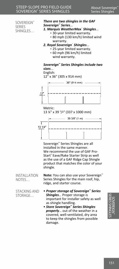
151
About Sovereign™ Series Shingles
STEEP-SLOPE PRO FIELD GUIDE SOVEREIGN™ SERIES SHINGLES
There are two shingles in the GAF Sovereign™ Series…1. Marquis WeatherMax® Shingles… • 30-year limited warranty. • 80 mph (130 km/h) limited wind
warranty.2. Royal Sovereign® Shingles… • 25-year limited warranty. • 60 mph (96 km/h) limited
wind warranty.
Sovereign™ Series Shingles include two sizes...English:12" x 36" (305 x 914 mm)
Metric:13 ¼" x 39 3/8" (337 x 1000 mm)
Sovereign™ Series Shingles are all installed in the same manner.We recommend the use of GAF Pro-Start® Eave/Rake Starter Strip as well as the use of a GAF Ridge Cap Shingle product that matches the color of your shingle.
Note: You can also use your Sovereign™ Series Shingles for the main roof, hip, ridge, and starter course.
• Proper storage of Sovereign™ Series Shingles… Proper storage is important for installer safety as well as shingle handling.
• Store Sovereign™ Series Shingles properly… out of the weather in a covered, well-ventilated, dry area to keep the shingles from possible damage.
SOVEREIGN™ SERIES SHINGLES…
INSTALLATION NOTES…
STACKING AND STORAGE…
REVIEW #10
SOVEREIG
N™
SERIES SHIN
GLES

152
Starter CoursesSTEEP-SLOPE PRO FIELD GUIDE SOVEREIGN™ SERIES SHINGLES
SOVE
REIG
N™
SERI
ES S
HIN
GLE
S
Use Pro-Start® Eave/Rake Starter Strip or WeatherBlocker™ Premium Eave/Rake Starter Strip... for all Sovereign™ Series Shingles. If using Pro-Start® or WeatherBlocker™ Starter Strips , fol-low their application instructions (see pages 143-149). Make sure nailing pattern will not be in between the tabs of the first shingle row. Installing hand-cut starter strips...1. Start at either rake edge.2. Use the same shingles for the
starter course as for the main roof… to insure all components last the entire warranty period.
3. Trim 6" (152 mm) off one end… so that the first course will fully overlap the starter course.
4. Trim the bottom tabs off… • This aligns the self-sealant with
the eave edge. • Sealed starters are more wind
resistant, rain resistant, and weather resistant.
5. Overhang starter shingles… 1/4"-3/4" (6-19 mm) over the drip edge at both rakes and eaves to keep water away from the structure.
6. Nail starter course 1 1/2"-3" (38-76 mm) from eaves… 6" (152 mm) on-center to properly secure from uplift.
7. Continue starter course… across the entire eave in the same manner.
INSTALLING STARTER COURSE…
STARTER COURSE DIAGRAM
SOVEREIG
N™
SERIES SHIN
GLES

153
Sovereign™ Series First Course
STEEP-SLOPE PRO FIELD GUIDE SOVEREIGN™ SERIES SHINGLES
1. Start with a full shingle… laid over the starter course.
• Align first course joints 4" (102 mm) min. from the starter course joints.
• Flush to the starter course edges.
2. Properly fasten the shingle… • Four fasteners per shingle (unless
code requires 6 fasteners). • Do not nail in the sealant… this can
damage the sealant, leaves the nails too high, and impedes sealing.
• Place fasteners correctly… • 5 5/8" (143 mm) from the
bottom edge (English). • 6" (152 mm) from the bottom
edge (metric). • Beware high nailing… high nailing
can cause blow-offs, or can allow shingles to slip off of decks.
3. Continue across the roof… in the same manner.
HOW TO INSTALL THE FIRST COURSE…
SOVEREIG
N™
SERIES SHIN
GLES
153

154
STANDARD NAILING PATTERN - four nails per shingle
13 1/4"(337 mm)
39 3/8" (1 m)
13 1/4"(337 mm)
(13 - 64 mm)1/2" - 2 1/2"
13 1/2" - 14 1/2"(343 - 368 mm)
(52 - 152 mm)2" - 6"
(52 - 152 mm)2" - 6"
(13 - 64 mm)1/2" - 2 1/2"
(13 - 64 mm)1/2" - 2 1/2"
(13 - 64 mm)1/2" - 2 1/2"
13 1/2" - 14 1/2"(343 - 368 mm)
39 3/8" (1 m)
ENHANCED NAILING PATTERN - six nails per shingle** required by some local codes and required for enhanced wind coverage on
certain products. See limited warranty for details.
154
NAILING LOCATIONS FOR GAF SOVEREIGN™
SERIES SHINGLES…
ENGLISH
METRIC
ROO
FIN
G
BASI
CSSovereign™ Series Nailing Locations
STEEP-SLOPE PRO FIELD GUIDE SOVEREIGN™ SERIES SHINGLES
SOVE
REIG
N™
SERI
ES S
HIN
GLE
S
(13 - 64 mm)1/2" - 2-1/2"
11" - 13"(279 - 333 mm) (279 - 333 mm)
(13 - 64 mm)1/2" - 2-1/2"
11" - 13"
(305 mm)
36" (914 mm)
12"
(13 - 64 mm)1/2" - 2-1/2"
(52 - 152 mm)2" - 6"
(52 - 152 mm)2" - 6"
(13 - 64 mm)1/2" - 2-1/2"
(305 mm)
36" (914 mm)
12"
Standard Nailing Pattern - four nails per shingle
Standard Nailing Pattern - four nails per shingle
Enhanced Nailing Pattern - six nails per shingle*
* Required by some local codes and required for enhanced wind coverage on certain products. See limited warranty for details.
Enhanced Nailing Pattern - six nails per shingle*
* Required by some local codes and required for enhanced wind coverage on certain products. See limited warranty for details.
SOVEREIG
N™
SERIES SHIN
GLES

155
ROO
FING
BA
SICSSovereign™ Series Second Course
STEEP-SLOPE PRO FIELD GUIDE SOVEREIGN™ SERIES SHINGLES
1. Trim first shingle… at the rake edge side of a full shingle to properly align the shingle’s cut-outs 6" (152 mm) Eng-lish size, 6 9/16" (167 mm) metric size.
2. Align shingle to top of cut-outs… The bottom edge of this shingle should rest just on top of the cut-outs of the shingle below it. Shingle exposure should be 5" (127 mm) for English size shingles and 5 5/8" (143 mm) for metric size shingles.
3. Do not “stretch” the exposure… aligning shingles higher than the tops of the cut-out creates problems…
• Ensures high nailing problems. • May cause exposed fasteners. • Creates cupping of shingles. • Will make the shingle’s appearance
look improper.
INSTALL THE SECOND COURSE…
Sovereign™ Series Nailing Locations
SOVEREIG
N™
SERIES SHIN
GLES

156156
1. Continue up the roof.2. Cut an additional half tab off of
each new shingle at the rake edge… trimming 6" (152 mm) off English size, 6 9/16" (167 mm) off metric and create the stair-step method of keeping the cut-outs aligned.
3. Course #6 is a half tab… install just a half tab shingle piece at course #6.
a. Make sure to fasten the half tab with 4 nails to prevent rake uplift.
4. Bring up full shingles courses from the eave… to fill out the stair-step pattern.
5. Course #7 starts over as in course #1 with new full shingle… Create a new stair step to continue up the roof.
w For step flashing, valley construction, and other flashing details, refer to Section 5.
Racking shingles… is when shingles are installed straight up the roof.
w Racking is not the preferred method of installing shingles because...
1. Improper nailing… The main reason GAF prefers the “stair step” method is to ensure proper nailing.
2. Nails left out… Many times shingles do not get the correct amount of fasteners with this method.
3. Racking can cause stress cracks… when bending the shingles to nail them.
4. Racking may also cause... an incorrect color blend.
INSTALLING3RD THROUGH6TH COURSES…
A NOTE ON THE “RACKING” METHOD…
ROO
FIN
G
BASI
CSSovereign™ Series Third and Remaining Courses
STEEP-SLOPE PRO FIELD GUIDE SOVEREIGN™ SERIES SHINGLES
SOVE
REIG
N™
SERI
ES S
HIN
GLE
SSOVEREIG
N™
SERIES SHIN
GLES

157
Stair Step And Racking Methods
STEEP-SLOPE PRO FIELD GUIDE SOVEREIGN™ SERIES SHINGLES
PROPER INSTALLATION METHOD
IMPROPER INSTALLATION METHOD
6" (152 mm) - English6 9/16" (167 mm) - Metric
Traditional Stair Step Method
6" (152 mm) - English6 9/16" (167 mm) - Metric
Racking Method
Sovereign™ Series Third and Remaining Courses
SOVEREIG
N™
SERIES SHIN
GLES

158158
1. Use a GAF Ridge Cap product (see page 210) or create from full shingles… Cut full shingles to make hip and ridge (H & R) shingles.
2. GAF recommends the installation of a GAF Ridge Cap product (see page 210).
3. Cut a full GAF Sovereign™ Series Shingle to make capping for hip and ridge.
• Taper cut for the best appearance. • Make 3 hip and ridge caps from
each full shingle.
1. Center over hip or ridge… to fully cover area.
2. Bend to conform to ridge… for best appearance. Note: In cold-weather applications on slopes 7:12 and greater, product might need to be preheated (leave it in a heated trailer or truck for the day) to 50 degrees or higher in order to bend it without breaking.
3. Align correct exposure… overexposing could lead to blow-offs.
• 5" (127 mm) English • 5 5/8" (143 mm) metric.4. Nail correctly… 1" (25 mm) from the
outside edge, and 5 5/8" (143 mm) English or 6" (152 mm) metric from the bottom edge for wind resistance.
5. Face nail the last piece… and seal the nail heads with plastic cement.
6. Install with the prevailing wind… To gain maximum wind resistance, install so dominant winds flow over shingles and not against the butt end.
MAKING HIP AND RIDGE SHINGLES…
INSTALLING HIP AND RIDGE SHINGLES…
ROO
FIN
G
BASI
CSSovereign™ Series Hip And Ridge Shingles
STEEP-SLOPE PRO FIELD GUIDE SOVEREIGN™ SERIES SHINGLES
SOVE
REIG
N™
SERI
ES S
HIN
GLE
SSOVEREIG
N™
SERIES SHIN
GLES

159
STEEP-SLOPE PRO FIELD GUIDE SOVEREIGN™ SERIES SHINGLES
Note: Make sure your gun is at a 90-degree angle from the roof when fastening cap shingle. Crooked nails are a frequent reason for cap shingle blow-off, as the self-seal will not touch the preceding cap shingle.
Sovereign™ Series Hip And Ridge Shingles
Cut shingle to make three 12"(305mm) x 12" (305mm) hip &ridge shingles from each strip
Taper cutfor bestappearance
5" (127 mm)exposure - English size5 5/8" (143 mm)exposure - Metric size
Nail 5 5/8" (143 mm) above buttfor English size.Nail 6 1/16" (159 mm) abovebutt for Metric size.And nail 1" (25 mm) from edge.
Bend hip & ridge shinglecentered over hip or ridge
NOTE: Face nail last piece and seal the nail heads with asphalt plastic cement.
Sovereign™ Series Hip And Ridge Shingles
SOVEREIG
N™
SERIES SHIN
GLES

160160
1. True or False? There are 4 different shingles in the GAF Sovereign™ Series.
A. True B. False
2. When installing Sovereign™ Series Shingles, the first course should be:
A. A full shingle. B. Trimmed 6" (152 mm). C. Trimmed 1 full tab. D. None of the above.
3. Why is it improper to nail in the self-sealant? A. It damages the sealant and places the nails too high. B. It seals the nails down. C. Nailing in the sealant breaks the plastic film on the
shingle. D. All of the above.
4. True or False? The “Racking Method” is not a preferred method of installing shingles.
A. True B. False
5. When cutting hip and ridge shingles from Sovereign™ Series Shingles, why is the head lap area of the shingle taper cut?
A. It reduces waste. B. It makes the shingle more wind resistant. C. It takes less time to cut the shingles. D. It provides the best appearance.
ROO
FIN
G
BASI
CSREVIEW #11STEEP-SLOPE PRO FIELD GUIDE
SOVE
REIG
N™
SERI
ES S
HIN
GLE
SSOVEREIG
N™
SERIES SHIN
GLES

161
ROO
FING
BA
SICS
GAF’s Timberline® Shingle was one of the first laminated shingles ever made.• Called “laminated” due to the way it
is made.• Two separate shingles… Laminated
shingles are actually two separate shingles.
• They are laminated together… The two shingles are laminated together to make one extra-thick shingle.
• The top section has the “saw-teeth”… Saw-teeth give the shingle its unique wood-shake look.
• The bottom section is the “backer strip”… This strip adds strength and depth to the shingle.
THE TWO SECTIONS OF A TIMBERLINE® SHINGLE
LAMINATED SHINGLES…
About Timberline® Series Shingles
STEEP-SLOPE PRO FIELD GUIDE TIMBERLINE® SERIES SHINGLES
Saw Teeth Section
Laminated Together
The Two Sections Of A Timberline® Shingle
Backer Strip Section
TIMBERLIN
E®
SERIES SHIN
GLES

162162
These are the shingles in the GAF Timberline® Series…1. Timberline Ultra HD® Shingles… • Lifetime limited warranty. • 130 mph (209 km/h) maximum
limited wind warranty.* • StainGuard® protection2. Timberline® ArmorShield™ II
Shingles… • Lifetime limited warranty. • 130 mph (209 km/h) maximum
limited wind warranty.* • SBS Modified IR shingle.3. Timberline® American Harvest®
Shingles… • Lifetime limited warranty. • 130 mph (209 km/h) maximum
limited wind warranty.*5. Timberline HD® Shingles… • Lifetime limited warranty. • 130 mph (209 km/h) maximum
limited wind warranty.*6. Timberline® Natural Shadow®
Shingles… • Lifetime limited warranty. • 130 mph (209 km/h) maximum
limited wind warranty.*7. Timberline® Cool Series® Shingles… • Lifetime limited warranty. • 130 mph (209 km/h) maximum
limited wind warranty.*
* In order to obtain the maximum wind coverage, the shingles must be installed using 6 nails per shingle and certain GAF Starter Strip products (only those with factory-applied adhesive) on the eaves and rakes. Shingles must be installed in strict accordance with published application instructions, particularly regarding nail placement.
Timberline® Shingles… • 39 3/8" (1 m) long. • 13 1/4" (337 mm) wide.
TIMBERLINE® SERIES SHINGLES…
About Timberline® Series Shingles
STEEP-SLOPE PRO FIELD GUIDE TIMBERLINE® SERIES SHINGLES
TIM
BERL
INE®
SERI
ES S
HIN
GLE
S
5 3/4" - 6 1/4" (146 mm - 159 mm)from bottom of shingle
13 1/4"(337 mm)
39 3/8" (1 m)
Self seal adhesive on back
Nail guide line
TIMBERLIN
E®
SERIES SHIN
GLES

163
Timberline® Shingles are available nationwide.
• Proper storage of Timberline® Shingles… Proper storage is important for installer safety as well as shingle handling.
• Store Timberline® Shingles properly… out of the weather in a covered, well-ventilated, dry area to keep the shingles from possible damage.
Use WeatherBlocker™ Premium Eave/Rake Starter Strip... Follow application instructions starting on page 143.
EXTREMELY IMPORTANT:High-nailing Timberline® Shingles can cause product failure.• Laminated shingles have two parts…
these parts are laminated together.• Your nailing is designed to keep both
parts together… Combined with the lamination adhesive, it helps holds these two pieces together.
• Nails must penetrate the double-ply area… Your nails must be placed through both sections, catching 1/4" (6 mm) of the backer strip.
• High nailing weakens wind resistance… Wind can lift shingles off a roof when they are nailed too high.
• Simply use the nail guide line… that is painted on every GAF Timberline® Series Shingle as a guide to ensure proper nailing.
INSTALLING STARTER COURSE…
Timberline® Series Starters
STEEP-SLOPE PRO FIELD GUIDE TIMBERLINE® SERIES SHINGLES
NATIONWIDEAVAILABILITY
STACKING AND STORAGE…
About Timberline® Series Shingles
TIMBERLIN
E®
SERIES SHIN
GLES
NOTES ON HIGH NAILING…
11 5/8" -14 5/8"(295 - 372 mm)
(13 - 64 mm)1/2" - 2 1/2"
11 5/8" -14 5/8"(295 - 372 mm)
(13 - 64 mm)1/2" - 2 1/2"
STANDARD NAILING PATTERN - four nails per shingle
5 3/4" - 6 1/4"(146 mm - 159 mm)
CORRECT NAILING PATTERN FOR GAF TIMBERLINE® SERIES SHINGLES…
Standard Nailing Pattern - four nails per shingle

164164
1. Start with a full shingle… • laid over the starter course. • flush to the eave and rake edge
starter shingles.2. Properly fasten the shingle… • At least four fasteners per shingle. • Do NOT nail in the sealant…
This places nails too high and interferes with proper sealing.
3. Nail correctly… 6" (152 mm) from the bottom.
4. Continue across the roof.
ROO
FIN
G
BASI
CSTimberline® Series First Course
STEEP-SLOPE PRO FIELD GUIDE TIMBERLINE® SERIES SHINGLES
TIM
BERL
INE®
SERI
ES S
HIN
GLE
S
(368 - 445 mm)
(13 - 64 mm)1/2" - 2 1/2"
(165 - 241 mm)6 1/2" - 9 1/2"
14 1/2" - 17 1/2"
(165 - 241 mm)6 1/2" - 9 1/2"
(368 - 445 mm)14 1/2" - 17 1/2"
ENHANCED NAILING PATTERN - six nails per shingle** required by some local codes and required for enhanced wind coverage on certain products.
See limited warranty for details.
(13 - 64 mm)1/2" - 2 1/2" 5 3/4" - 6 1/4"
(146 mm - 159 mm)
TIMBERLIN
E®
SERIES SHIN
GLES
A 1/4"-3/4" (6-19 mm) overhang is required on all Weather Stopper® Golden Pledge® and Silver Pledge® Installations.
WEATHER STOPPER® GOLDEN PLEDGE® AND SILVER PLEDGE® NOTE...
GAF
Underlayment
Start at either rake and lay in either direction
Starter
Course
First Course
For maximum windresistance along rakes,install any GAF starterstrip containing sealant orcement shingles tounderlayment and eachother in a 4" (102mm)width of asphalt plasticroof cement.
Place shingle 14" -3 4"(6 - 19mm) overeaves and rake edgesto provide drip edge.
Continue first coursewith whole shingles.
INSTALLING THE FIRST COURSE…
Enhanced Nailing Pattern - six nails per shingle*
* Required by some local codes and required for enhanced wind coverage on certain products. See limited warranty for details.
Note: These singles MUST be nailed a nominal 6" (152 mm) from bottom of shingle, above the cut outs, as shown. Nails must not be exposed.

165
ROO
FING
BA
SICSTimberline® Series Second Course
STEEP-SLOPE PRO FIELD GUIDE TIMBERLINE® SERIES SHINGLES
1. Trim to align pattern… Trim 6" (152 mm) from the rake edge side of the shingle to properly align the Timberline® Shingle design.
2. Align to tops of saw-teeth… of the under-lying shingle. Shingle exposure should be 5 5/8" (143 mm).
3. Do NOT overexpose… Aligning shingles higher than the tops of the saw-teeth can lead to problems.
• Creates cupping… Timberline’s thick structure can make the shingles cup or curve when overexposed.
• Bad appearance… The unique wood-shake look of Timberline® Series can be lost or changed by overexposing.
• High nailing... When aligned too high, your fasteners will be installed too high, missing the double-ply area.
INSTALLING THE SECOND COURSE…
First CourseSecond Course
6"
(152mm)
Start second course with atrimmed shingle as shown.Continue with whole shingle
GAF
Underlayment
Trim 6" (152mm)from rake end offirst shingle
Timberline® Series First Course
TIMBERLIN
E®
SERIES SHIN
GLES

166166
1. Trim 11" (279 mm) off… the rake edge side of a full shingle to continue proper alignment of the Timberline® Shingle design.
2. Use at least three fasteners… on this shortened shingle.
3. Align as with other courses.
THIRD COURSE DIAGRAM…
INSTALLING THE THIRD COURSE…
ROO
FIN
G
BASI
CSTimberline® Series Third Course
STEEP-SLOPE PRO FIELD GUIDE TIMBERLINE® SERIES SHINGLES
TIM
BERL
INE®
SERI
ES S
HIN
GLE
S
First Course
Second Course
11"
(279mm)
ThirdCourse
6"
(152mm)
Start third course with atrimmed shingle as shown.Continue with whole shingle
Trim 11" (279mm)rake end of first shingle
GAF
Underlayment
TIMBERLIN
E®
SERIES SHIN
GLES

167
ROO
FING
BA
SICSTimberline® Series Fourth Course
STEEP-SLOPE PRO FIELD GUIDE TIMBERLINE® SERIES SHINGLES
1. Trim 17" (432 mm) off… the rake edge side of a full shingle to continue proper alignment of the Timberline® design.
2. Use a minimum of two fasteners… on this shortened shingle.
3. Align as with other courses.4. Start again with a full shingle… at the
fifth course.5. Repeat the 2nd, 3rd, 4th, and 5th course
methods… going up the roof along the rake edge.
• Trim 6" (152 mm) from the second course.
• Trim 11" (279 mm) from the third course.
• Trim 17" (432 mm) from the fourth course.
• Install full shingle.6. Repeat this method completely… This
stepping method will result in the unique look of a GAF Timberline® roof.
INSTALLING FOURTH AND REMAINING COURSES…
Timberline® Series Third Course
TIMBERLIN
E®
SERIES SHIN
GLES

168168
w Racking is not acceptable… on ANY GAF laminated shingles, including Timberline® Series.
• Creates poor appearance… The straight-up roof racking method distorts the natural design pattern of Timberline® Shingles.
• Improper nailing… Racking often leads to improper nailing.
• Shingles left un-nailed... at the first pass can mistakenly be left un-nailed.
• Heavyweight shingles like Tim-berline® Shingles... need proper nailing.
• Can damage shingles… bending each shingle to nail the “blind nail” can crack the double-ply lamina-tion.
• Racking can cause color blend problems… Installing shingles straight up the roof can create up-and-down color lines on a roof. Note: This color problem is not a manufacturing defect.
On Weather Stopper® Golden Pledge® and Silver Pledge® installations, rack-ing is not accepted with Timberline®
Series Shingles.
w For flashing, valley construction, and other flashing details, refer to Section 5.
w For hip and ridge shingle installation, refer to “Installing Enhanced Cap-ping” starting on pages 210-220.
WEATHER STOPPER® GOLDEN PLEDGE® AND SILVER PLEDGE® NOTE…
RACKING LAMINATED SHINGLES…
ROO
FIN
G
BASI
CSTimberline® Series And Racking
STEEP-SLOPE PRO FIELD GUIDE TIMBERLINE® SERIES SHINGLES
TIM
BERL
INE®
SERI
ES S
HIN
GLE
STIMBERLIN
E®
SERIES SHIN
GLES

169
ROO
FING
BA
SICS
1. What are the names for the two sections of a Timberline® Shingle?
A. The top and the bottom. B. Front part, back part. C. Upper edge, lower edge. D. Saw-teeth section, backer strip section.
2. To fasten Timberline® Shingles properly, where should the fasteners be installed?
A. In the sealant. B. Above the cut-outs. C. In the starter area. D. In the nail guide line.
3. For Timberline® Shingles, on what course do you install a full shingle to start the sequence over again?
A. Third course. B. Fourth course. C. Fifth course. D. Every other course.
4. True or False: Racking Timberline® Series Shingles can distort the designed alignment, lead to improper nailing, and possibly damage the shingles.
A. True B. False
REVIEW #12STEEP-SLOPE PRO FIELD GUIDE Timberline® Series And Racking
TIMBERLIN
E®
SERIES SHIN
GLES

170170
w There are three shingles in this section…
1. Grand Sequoia®
• Lifetime limited warranty. • 130 mph (209 km/h) maximum
limited wind warranty.* • Value Collection2. Grand Sequoia® ArmorShield™
• Lifetime limited warranty. • 130 mph (209 km/h) maximum
limited wind warranty.* • Value Collection • Class 4 SBS Modified IR shingle.3. Grand Canyon®
• Lifetime limited warranty. • 130 mph (209 km/h) maximum
limited wind warranty.* • Ultra-Premium Collection
Note: Shingle shown in drawings are one of 6 different design patterns.
* In order to obtain the maximum wind coverage, the shingles must be installed using 6 nails per shingle and certain GAF Starter Strip products (only those with factory-applied adhesive) on the eaves and rakes. Shingles must be installed in strict accordance with published application instructions, particularly regarding nail placement.
GRAND SEQUOIA® AND GRAND CANYON®
SHINGLES…
ROO
FIN
G
BASI
CSSTEEP-SLOPE PRO FIELD GUIDE GRAND SEQUOIA®/GRAND CANYON® SHINGLES
GRAN
D SE
QUOI
A® / GR
AND
CAN
YON®
SHIN
GLES
About Grand Sequoia®/Grand Canyon® Shingles

171
ROO
FING
BA
SICSGrand Sequoia®/ Grand Canyon® Starter Courses
Grand Sequoia® and Grand Canyon® Shingles are NOT available in ALL areas. See gaf.com for regional availability.
Note: In the sections that follow, all references to Grand Sequoia® Shingles also apply to Grand Sequoia® ArmorShield™ and Grand Canyon® Shingles.
• Proper storage of Grand Sequoia® Shingles… Proper storage is important for installer safety as well as shingle handling.
• Store Grand Sequoia® Shingles properly… out of the weather in a covered, well-ventilated, dry area to keep the shingles from possible damage.
w Two starter courses are needed to fill out Grand Sequoia® Shingles’ extra width and thickness.
First Starter Course… 1. Use WeatherBlocker™ Premium Eave/
Rake Starter Strip... and follow applica-tion instructions starting on page 143.
INSTALL TWO STARTER COURSES…
NATIONWIDE VAILABILITY
STEEP-SLOPE PRO FIELD GUIDE GRAND SEQUOIA®/GRAND CANYON® SHINGLES
STACKING AND STORAGE…
About Grand Sequoia®/Grand Canyon® Shingles
GRAND SEQUOIA®/
GRAND CANYON®
SHINGLES

172172
Second Starter Course… 1. Use color-coordinated Starter-
Match™ Starter Strip Shingles (for-merly known as Grand Sequoia®/Grand Canyon® Starter Strip) as second starter.
2. Trim 5" (127 mm) off of Starter-Match™Starter Strip… to ensure the first course overlaps the seam.
3. Place second starter directly over first starter… to give the correct depth to the starter course.
4. Align second starter even with first…at the rakes and eaves.
5. Nail second starter… • 6" (152 mm) from eave. • Fasten with at least 4 nails
per shingle; see diagram below.
INSTALLING SECOND STARTER COURSE…
ROO
FIN
G
BASI
CSGrand Sequoia®/ Grand Canyon® Starter Courses
STEEP-SLOPE PRO FIELD GUIDE GRAND SEQUOIA®/GRAND CANYON® SHINGLES
SECOND STARTER COURSE DIAGRAM…
GRAN
D SE
QUOI
A® / GR
AND
CAN
YON®
SHIN
GLES

173
ROO
FING
BA
SICS
1. Trim 1/2" (13 mm) off… at the rake edge side of a full shingle to properly align Grand Sequoia’s design.
2. Place shingle over starter course… aligning flush to the starters at the rake edge and the eaves.
3. Use five fasteners… to properly hold this 40" (1,016 mm) long shingle. See “Standard Nailing Pattern” below.
4. When 6 nails are required by code… or for high wind limited warranty, use “Enhanced Nailing Pattern” below.
5. Fasten in the nail guide line… Fasten in the white nail guide line that is on every Grand Sequoia® Shingle (11" [279 mm] from the shingle bottom).
INSTALLING THE FIRST COURSE…
Grand Sequoia®/ Grand Canyon®
First CourseSTEEP-SLOPE PRO FIELD GUIDE GRAND SEQUOIA®/GRAND CANYON® SHINGLES
Standard Nailing Pattern - five nails per shingle
Enhanced Nailing Pattern - six nails per shingle*
* Required by some local codes and required for enhanced wind coverage on certain products. See limited warranty for details.
Note: These singles MUST be nailed a nominal 6" (152 mm) from bottom of shingle, above the cut outs, as shown. Nails must not be exposed.
Grand Sequoia®/ Grand Canyon® Starter Courses
GRAND SEQUOIA®/
GRAND CANYON®
SHINGLES

174
INSTALLING THE SECOND COURSE…
174
6. Fasten properly… As with all shingles, proper fastening is the key to a long-lasting system.
• Overdriving fasteners… can damage the shingles.
• Underdriving fasteners… can lessen their wind resistance.
• Fastening too high… leads to blow-offs and shingles slipping off of roofs.
7. Crowding can cause buckles… Place the next shingle close to the first without crowding them together.
8. Continue across the roof… on first course using full shingles.
A 1/4"-3/4" (6-19 mm) overhang is
required on all Weather Stopper® Golden Pledge® and Silver Pledge® Installations.
INSTALLING THE FIRST COURSE…
WEATHER STOPPER® GOLDEN PLEDGE® AND SILVER PLEDGE® NOTE…
Grand Sequoia®/ Grand Canyon®
First CourseSTEEP-SLOPE PRO FIELD GUIDE GRAND SEQUOIA®/GRAND CANYON® SHINGLES
1. Place a full shingle over the previous course… using alignment notches, align the bottom flush to the square cut-outs.
2. Correctly place the design pattern… Set shingles back using 5" (127 mm) alignment slits.
• Starting from the right… set back 5 1/2" (140 mm) toward the left.
• Starting from the left… set back 5" (127 mm) toward the right.
3. Trim off the 5" (127 mm) from the rake edge side… to align flush to the rake edge.
Note: Includes alignment notch.4. Fasten in place… to secure to the
deck.
GRAN
D SE
QUOI
A® / GR
AND
CAN
YON®
SHIN
GLES

175
ROO
FING
BA
SICS
1. Continue up the rake edge2. Set using alignment slits… Trimming the sides 5" (127 mm) from subsequent courses at rake edge sides. • Trim 10" (254 mm) from third
course. • Trim 15" (381 mm) from the fourth
course, etc.3. Continue this pattern... To obtain the
best appearance of the design pattern, continue trimming 5" (127 mm) off shingles to the ninth course.
4. Install a full shingle… at the ninth course to begin the pattern again. (A full shingle can be used to start any odd numbered courses if necessary; however, to obtain the best appearance, follow the instructions above.)
5. Strike a horizontal chalk line… every six courses to ensure proper alignment.
Racking should not be used… The unique design pattern of Grand Sequoia® Shingles is disrupted when the straight-up racking method is used; this method can lead to leaking and damage to shingles.
On Weather Stopper® Golden Pledge® and Silver Pledge® installations, racking Grand Sequoia® Shingles is not acceptable.
THIRD AND SUBSEQUENT COURSES…
INSTALLATION NOTE: RACKING
WEATHER STOPPER® GOLDEN PLEDGE® AND SILVER PLEDGE® NOTE...
Grand Sequoia®/ Grand Canyon®
CoursesSTEEP-SLOPE PRO FIELD GUIDE GRAND SEQUOIA®/GRAND CANYON® SHINGLES
Grand Sequoia®/ Grand Canyon®
First Course
GRAND SEQUOIA®/
GRAND CANYON®
SHINGLES

176176
Measuring at the very top of the shingle: • Trim 5" (127 mm) off second course. • Trim 10" (254 mm) off third course. • Trim 15" (381 mm) off fourth
course. • Continue to trim 5" (127 mm) more
off of each new course. • At ninth course, install a full shingle. • After the full shingle, continue
trimming an additional 5" (127 mm) from courses.
w For step flashing, valley construction,
and other flashing details, refer to Section 5.
w For hip and ridge shingle installation, refer to “Installing Enhanced Capping” starting on pages 210-220.
INSTALLING THE COURSES…
ROO
FIN
G
BASI
CSGrand Sequoia®/ Grand Canyon® Courses Diagram
STEEP-SLOPE PRO FIELD GUIDE GRAND SEQUOIA®/GRAND CANYON® SHINGLES
GRAN
D SE
QUOI
A® / GR
AND
CAN
YON®
SHIN
GLES
177
ROO
FING
BA
SICS
1. Which of the Grand Canyon®, Grand Sequoia® or Grand Sequoia® ArmorShield™ Shingles is referred to as an Ultra-Premium Collection Shingle?
A. Grand Canyon®
B. Grand Sequoia®
C. Grand Sequoia® ArmorShield™
2. Why are two starter courses needed when installing Grand Sequoia®, Grand Canyon® and Grand Sequoia® ArmorShield™ Shingles?
A. To fill cracks and voids. B. For wind uplift. C. To align them properly. D. To fill out Grand Sequoia®, Grand Canyon® and Grand
Sequoia® ArmorShield™ Shingles' extra width and thickness.
3. Why is racking Grand Canyon®, Grand Sequoia® or Grand Sequoia® ArmorShield™ Shingles not recom-mended?
A. It makes installing too easy. B. Racking will increase the chances of mold growth. C. Racking can disrupt the unique design pattern of
these shingles, and can lead to leaking and damage to shingles.
D. All of the above.
4. Why is it recommended that you clip the shingle’s top corners in the valley area? (Hint: See Valley Construction Section)
A. To keep leaves from collecting there. B. To keep water flowing into the valley center. C. To keep the ice in the valley. D. Both A and B.
5. True or False: When installing step flashing with Grand Sequoia®, Grand Canyon® and Grand Sequoia® Armor-Shield™ Shingles, you install step flashing before install-ing the second starter course. (Hint: See Step Flashing Section)
A. True B. False
REVIEW #13STEEP-SLOPE PRO FIELD GUIDE
Grand Sequoia®/ Grand Canyon® Courses Diagram
GRAND SEQUOIA®/
GRAND CANYON®
SHINGLES

178178
ROO
FIN
G
BASI
CSW
OODL
AND®
SHIN
GLES
Woodland® Shingles are premium-design laminated shingles carrying… • Lifetime l imited warranty • 130 mph (209 km/h) maximum
limited wind warranty* • StainGuard® protection
* In order to obtain the maximum wind coverage, the shingles must be installed using 6 nails per shingle and certain GAF starter strip products (only those with factory-applied adhesive) on the eaves and rakes. Shingles must be installed in strict accordance with published application instructions, particularly in regard to nail placement.
Woodland® Shingle…16 5/8" x 40" (422 mm x 1016 mm)
Note: Shingles shown in drawings are one of 6 different design patterns.
Woodland® Shingles are available nationwide.
• Proper storage of Woodland® Shingles… Proper storage is important for installer safety as well as shingle handling.
NATIONWIDEAVAILABILITY
STACKING AND STORAGE…
WOODLAND®
SHINGLES…
About Woodland® Shingles
STEEP-SLOPE PRO FIELD GUIDE WOODLAND® SHINGLES
GRAND SEQUOIA®/ GRAND
CANYON® SHINGLES

ADVANTAGES OF THE TRUSLATE™ ROOFING SYSTEM
179
ROO
FING
BA
SICSInstalling TruSlate™ Premium Roofing
179
• Store Woodland® Shingles properly… out of the weather in a covered, well-ventilated, dry area to keep the shingles from possible damage.
w Two starter courses are needed to fill out Woodland® Shingles’ extra width and thickness.
w First Starter Course… Split GAF WeatherBlocker™ Premium Eave/Rake Starter Strip into ½ height pieces 8.5" x 40" (216 x 1,016 mm) and install along the eaves.
Overhang starter strip shingles… ¼''-¾" (6-19 mm) over the drip edge at both rakes and eaves to keep water away from the structure.
w Second Starter Course…Install full-height GAF WeatherBlocker™ Starter Strips. Do NOT split second starter course strips in half.
INSTALL TWO STARTER COURSES…
Woodland® ShinglesStarter Course
STEEP-SLOPE PRO FIELD GUIDE WOODLAND® SHINGLES
GAF Underlayment
Nail approximately11
2"- 3" (38 - 76mm)above the butt edge ofthe shingle andapproximately 1" - 2"(25 - 51mm) and10" - 12" (254 - 305mm)in from of each side. 4nails per full shingle.
Overlap eaves edge starterstrip at least 3" (76 mm)
Start at either rake andlay in either direction.Continue with full splitstarter strip shingle
Place shingle 14" -3 4"(6 - 19mm) over eavesand rake edges toprovide drip edge.
TM
For maximum wind resistance along rakes, installGAF WeatherBlocker starter strip or cementshingles to underlayment and each other in a 4"(102 mm) width of asphalt plastic cement.
Begin starter course with 10” (254mm)length of WeatherBlocker Starter StripShingle fastened with 2 nails.
TM
About Woodland® Shingles
WOODLAND
® SHINGLES
FIRST STARTER COURSEDIAGRAM…

180180
WOO
DLAN
D® SH
INGL
ES
Note: To prevent sealant from being visible at the eave, the second course of GAF WeatherBlocker™ Starter Strips must be installed with the sealant location away from the eave edge as shown. Sealant on the back of the Woodland® Shingles will seal shingles to the starter course along the eaves.
1. Trim 30" (762 mm) off of rake edge of first WeatherBlocker™ Starter Strip Shingle to ensure the first course overlaps the seam.
2. Continue with full-size starter strip shingle.
3. Place second starter directly over first starter strip… to give the correct depth to the starter course.
4. Align second starter strip even with first at the rakes and eaves.
5. Nail second starter strip… 1 ½" – 3" (38-76 mm) above butt edge of shingle.
1. If starting from the left... trim 1/2" (13 mm) notch from first shingle.
2. Use five fasteners… to properly hold this 40" (1016 mm) long shingle (see figure on next page).
3. When 6 nails are required by code… or for high-wind ltd. warranty, use enhanced nailing pattern on next page.
4. Fasten along the nail guide marks… Nominally 8 ½" (216 mm) from bottom of long tab.
HOW TO INSTALL THE FIRST COURSE OF WOODLAND SHINGLES…
Woodland® ShinglesSecond Starter Course
STEEP-SLOPE PRO FIELD GUIDE WOODLAND® SHINGLES
WOODLAND
® SHINGLES
INSTALLING SECOND STARTER COURSE…
SECOND STARTER COURSEDIAGRAM…

181
5. Fasten properly… as with all shingles, proper fastening is the key to a long-lasting system.
• Overdriving fasteners… can damage the shingles.
• Underdriving fasteners… can lessen their wind resistance.
• Fastening too high… leads to blow-offs and shingles slipping off of roofs.
6. Crowding can cause buckles… Place the next shingle close to the first without crowding them together.
7. Continue across the roof… on first course using full shingles.
A ¼"-¾" (6-19 mm) overhang is required on all Weather Stopper® Golden Pledge® and Silver Pledge® Installations.
WEATHER STOPPER® GOLDEN PLEDGE® AND SILVER PLEDGE® NOTE…
Woodland® ShinglesFirst Course
STEEP-SLOPE PRO FIELD GUIDE WOODLAND® SHINGLES
Standard Nailing Pattern - Five nails per shingle
Enhanced Nailing Pattern - six nails per shingle*
* Required by some local codes and required for enhanced wind coverage on certain products. See limited warranty for details.
Woodland® ShinglesSecond Starter Course
WOODLAND
® SHINGLES

182182
WOO
DLAN
D® SH
INGL
ES
1. Trim 5" (127 mm) from rake edge of first shingle… to align flush to the rake edge.
2. If trimmed shingle starts with long tab, place bottom of shingle 5/8" (16 mm) below keyway.
3. Shingle exposure... 6 1/2" (165 mm) to 7 1/8" (181 mm).
4. Continue with whole shingles.
1. Trim 10" (254 mm) from rake edge of first shingle… to align flush to the rake edge.
2. If trimmed shingle starts with long tab, place bottom of shingle 5/8" (16 mm) below keyway.
3. Continue with whole shingles.
THIRD COURSE…
SECOND COURSE…
Woodland® ShinglesCourses
STEEP-SLOPE PRO FIELD GUIDE WOODLAND® SHINGLES
WOODLAND
® SHINGLES

183
1. Strike a horizontal chalk line… approximately every six courses to as-sure proper alignment with eaves.
2. Trim 15" (381 mm) from rake end of first shingle… Continue with whole shingles. Repeat the 1st - 4th course instructions on the remaining courses, starting the fifth course with a full shingle.
Racking should not be used… the unique design pattern of Woodland® Shingles is disrupted when the straight-up racking method is used; this method can lead to leaking and damage to shingles.
On Weather Stopper® Golden and Silver Pledge® installations, racking of shingles is not accepted.
w For step flashing, valley construc-tion, and other flashing details, refer to Section 5.
w For hip and ridge shingle installa-tion, refer to “Installing Enhanced Capping” Section starting on pages 210-220.
INSTALLTHE FOURTH AND REMAINING COURSES…
INSTALLATION NOTE: RACKING
Woodland® ShinglesCourses
STEEP-SLOPE PRO FIELD GUIDE WOODLAND® SHINGLES
Woodland® ShinglesCourses
WOODLAND
® SHINGLES
Woodland® ShinglesCourses
STEEP-SLOPE PRO FIELD GUIDE WOODLAND® SHINGLES

184184
WOO
DLAN
D® SH
INGL
ES
1. True or False? A trimmed Woodland® Shingle or full strip of WeatherBlocker™ Premium Eave/Rake Starter Strip can be used as the first starter course to install Wood-land® Shingles.
A. True B. False
2. What is the correct number of fasteners for a standard application of Woodland® Shingles?
A. 4 B. 5 C. 6 D. 7
3. What is the correct GAF Ridge Cap Shingle for use with Woodland® Shingles?
A. Timberline® Shingles B. Royal Sovereign® Shingles. C. Slateline® Shingles. D. None of the above.
4. How many courses are run before starting again with a full shingle?
A. 4 B. 5 C. 6 D. 7
5. Because of Woodland® Shingles' detailed design, the preferred valley methods are: (Hint: See Valley Construc-tion Section)
A. Woven valley and closed cut valley. B. Open valley and open California valley. C. Open valley only. D. Closed cut valley and open valley.
REVIEW #14STEEP-SLOPE PRO FIELD GUIDE
WOODLAND
® SHINGLES

185
ROO
FING
BA
SICS
Sienna® Shingles are premium-design laminated shingles carrying… • Lifetime limited warranty • 130 mph (209 km/h) maximum
limited wind warranty* • StainGuard® protection
* In order to obtain the maximum wind coverage, the shingles must be installed using 6 nails per shingle and certain GAF Starter Strip prod-ucts (only those with factory-applied adhesive) on the eaves and rakes. Shingles must also be installed in strict accordance with published application instructions, particularly regarding to nail placement.
Sienna® Shingle…17 3/8" x 40" (441 x 1016 mm)
Sienna® Shingles are available nationwide.
• Proper storage of Sienna® Shingles… Proper storage is important for installer safety as well as shingle handling.
• Store Sienna® Shingles properly… out of the weather in a covered, well-ventilat-ed, dry area to keep the shingles from possible damage.
STACKING AND STORAGE…
NATIONWIDEAVAILABILITY
SIENNA®
SHINGLES…
40"(1016mm)
17 3/8"(441mm)
Alignment slits
Self-sealadhesive on back
REVIEW #14Sienna® First Course
STEEP-SLOPE PRO FIELD GUIDE SIENNA® SHINGLES
SIENNA®
SHINGLES

186186
SIENNA®
SHINGLES
w Two starter courses are needed to fill out Sienna® Shingles’ extra width and thickness.
.First starter course...Use WeatherBlocker™ Premium Eave/Rake Starter Strip (follow application instructions starting on page 143).
Second Starter Course… 1. Use color-coordinated Starter-
Match™ Starter Strip Shingles as second starter.
2. Trim 5" (127 mm) off of Starter-Match™ Starter Strip Shingles… to ensure the first course overlaps the seam.
3. Place second starter strip directly over first starter… to give the cor-rect coverage and color.
4. Align second starter strip even with first… at the rakes and eaves.
5. Nail second starter strip… • 6" (152 mm) from eave. • Fasten with at least 4 nails per
shingles (see drawing below).
A 1/4"-3/4" (6-19 mm) overhang is required on all Weather Stopper® Golden and Silver Pledge® Installa-tions.
1. Start with full shingle… • Install flush with starter course. • Install left to right or right to left.2. Use four fasteners… The standard
pattern is four fasteners. See “ Stan-dard Nailing Pattern” on next page.
3. Use six fasteners if required… the alternate pattern is six fasteners if required by local code or for enhanced warranty. See “Enhanced Nailing Pattern” on next page.
Sienna® Starter Courses
STEEP-SLOPE PRO FIELD GUIDE SIENNA® SHINGLES
SIEN
NA®
SHIN
GLES
INSTALLING SECOND STARTER COURSE…
INSTALLING THE FIRST COURSE…
WEATHER STOPPER® GOLDEN PLEDGE® AND SILVER PLEDGE® NOTE…
SIENNA®
SHINGLES
INSTALL TWO STARTER COURSES…
INSTALL THE FIRST STARTER COURSE…
SECOND STARTER COURSEDIAGRAM…

187
4. Place fasteners correctly… • 2" (51 mm) above top of wide cut-
outs. • Outside nails ½"-1" (13-25 mm) from
edges. • Inside nails 12 ¾"-13 ¾" (324-349
mm) from each side. • Beware of high nailing… high nailing
can cause blow-offs, or can cause shingles to slip off decks.
5. Continue across the roof... in the same manner.
Sienna® First Course
STEEP-SLOPE PRO FIELD GUIDE SIENNA® SHINGLES
12 3/4" - 13 3/4" 12 3/4" - 13 3/4"
(13 - 25 mm)1/2" - 1"
(324 - 349 mm)
(13 - 25 mm)1/2" - 1"
(324 - 349 mm)
12 3/4" - 13 3/4" 12 3/4" - 13 3/4"
(13 - 25 mm)1/2" - 1"
(324 - 349 mm)
(13 - 25 mm)1/2" - 1"
(324 - 349 mm)
(38 - 64 mm)1 1/2" - 2 1/2"
2" (51 mm)
2" (51 mm)
STANDARD NAILING PATTERN - four nails per shingle
ENHANCED NAILING PATTERN - six nails per shingle*Two high nails should be located just below the shadow line.
* required by some local codes and required for enhanced wind coverage on certain products.See limited warranty for details.
Standard Nailing Pattern - four nails per shingle
Enhanced Nailing Pattern - six nails per shingle*
* Required by some local codes and required for enhanced wind coverage on certain products. See limited warranty for details.
Sienna® Starter Courses
SIENNA®
SHINGLES

188188
ROO
FIN
G
BASI
CS
SIENNA®
SHINGLES SIEN
NA®
SHIN
GLES
1. Trim ½ triangular tab [6 2/3" (169 mm)]... from the rake end of the first shingle.
2. Align shingle… such that the bottom of the triangular tab in the second and subsequent shingle courses is flush with the top of the wide cut-outs giving a 5 1/2" (140 mm) exposure.
3. Continue with full shingles… across the roof.
1. Trim 1 triangular tab [13 1/3" (339 mm)] from the rake end of the first shingle.
2. Continue… with full shingles across the roof.
1. Trim 1 ½" triangular tabs [20" (508 mm)]... from the rake end of the first shingle.
2. Continue… with full shingles across the roof.
3. Starting with the fifth course with a full shingle... repeat the first – fourth course instructions on the remaining courses.
4. Strike a chalk line every 6 courses to check alignment with eaves... remembering to use the alignment slit from the underlying shingle as a guide.
5. Align courses carefully… to avoid overexposing, high nailing, exposed nail heads, or altering design.
INSTALL THE THIRD COURSE…
INSTALLTHE FOURTH AND REMAINING COURSES…
SECOND COURSE
Sienna® Shingle Courses
STEEP-SLOPE PRO FIELD GUIDE SIENNA® SHINGLES
First Course
Second CourseThird Course
13 1/3"
(339mm)
GAF
Underlayment
Trim 1 triangular tab (13 1/3"(339 mm)) from rake end of firstshingle. Use alignment slit alongtop as reference point
Start third course with atrimmed shingle as shown.Continue with whole shingle
First Course
Second Course
GAF
Underlayment
Trim 12 triangular tab 6 2/3"(169 mm) from rake end offirst shingle. Use alignment slitalong top as reference point
Alignment Slit
Start second course with atrimmed shingle as shown.Continue with whole shingle
SIENNA®
SHINGLES

189
ROO
FING
BA
SICS
Do NOT lay Sienna® Shingles straight up the roof, as this procedure can cause an incorrect color blend and may damage the shingles as well.
w For step flashing, valley construction, and other flashing details, refer to Section 5.
w For hip and ridge shingle installation, refer to “Installing Enhanced Capping” starting on pages 210-220.
Sienna® Shingle Courses
STEEP-SLOPE PRO FIELD GUIDE SIENNA® SHINGLES
Sienna® Shingle Courses
SIENNA®
SHINGLES
INSTALLATION NOTE:RACKING…

190190
ROO
FIN
G
BASI
CS
SIENNA®
SHINGLES SIEN
NA®
SHIN
GLES
1. True or False? A full strip of WeatherBlocker™ Pre-mium Eave/Rake Starter Strip should be used as the first starter course to install Sienna® Shingles.
A. True B. False
2. What is the correct number of fasteners for a standard application of Sienna® Shingles?
A. 4 B. 5 C. 6 D. 7
3. Which GAF Ridge Cap Shingle can be used with Sienna® Shingles?
A. Timberline® Shingles. B. Royal Sovereign® Shingles. C. Timbertex® Shingles. D. None of the above.
4. How many courses are run before starting again with a full shingle?
A. 4 B. 5 C. 6 D. 7
5. Because of Sienna’s detailed design, the preferred valley methods are: (Hint: See Valley Construction Section)
A. Woven valley and closed cut valley. B. Open valley and open California valley. C. Closed cut valley and open valley. D. Open valley only.
REVIEW #15STEEP-SLOPE PRO FIELD GUIDE
SIENNA®
SHINGLES
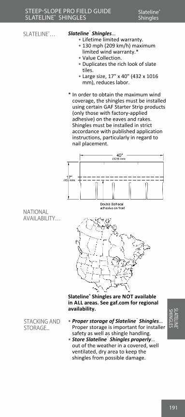
191
ROO
FING
BA
SICS
Slateline® Shingles… • Lifetime limited warranty. • 130 mph (209 km/h) maximum
limited wind warranty.* • Value Collection. • Duplicates the rich look of slate
tiles. • Large size, 17" x 40" (432 x 1016
mm), reduces labor.
* In order to obtain the maximum wind coverage, the shingles must be installed using certain GAF Starter Strip products (only those with factory-applied adhesive) on the eaves and rakes. Shingles must be installed in strict accordance with published application instructions, particularly in regard to nail placement.
Slateline® Shingles are NOT available in ALL areas. See gaf.com for regional availability.
• Proper storage of Slateline® Shingles… Proper storage is important for installer safety as well as shingle handling.
• Store Slateline® Shingles properly… out of the weather in a covered, well ventilated, dry area to keep the shingles from possible damage.
SLATELINE®…
NATIONAL AVAILABILITY…
STACKING AND STORAGE...
Slateline® Shingles
STEEP-SLOPE PRO FIELD GUIDE SLATELINE® SHINGLESREVIEW #15
SLATELINE®
SHINGLES

192
12" (305 mm)Alignment Slits
12" (305 mm)Alignment Slits
STANDARD NAILING PATTERN - six nails per shingle
7 1/2" - 8 1/2"(191 -216 mm)
(25 - 38 mm)1" - 1 1/2"
(25 - 38 mm)1" - 1 1/2"
15 1/2" - 16 1/2"(394 -419 mm)
7 1/2" - 8 1/2"(191 -216 mm)
15 1/2" - 16 1/2"(394 -419 mm)
9"(229 mm)
SLATELINE®
SHINGLES
w Two starter courses are needed to fill out Slateline® Shingles’ extra width and thickness.
Use WeatherBlocker™ Premium Eave/Rake Starter Strip... Follow application instructions starting on page 143.
1. Start with a full shingle… • Install ¼" – ¾" (16-19 mm) over
eave and rake edges. • Install flush with starter course
overhang to provide drip edge.2. Use six fasteners… to properly secure
Slateline® Shingles. See “Nailing Pattern” below.
3. Fasten 9" (229 mm) from the bottom edge of the shingle in between the two self-seal lines.
4. High nailing precaution… • High nailing reduces wind
resistance. • High nailing can cause shingles to
slip off of the roof deck.5. Drive fasteners flush to shingle… • Overdriving fasteners… can
damage shingles. • Underdriving… can lead to shingle
blow-offs.6. Continue first course… across the eave
using full shingles.7. Avoid crowding shingles… place
shingles close but not too close. • Crowding can cause shingles to
buckle.
INSTALLING STARTER COURSE…
INSTALLING THE FIRSTCOURSE…
Slateline® First Course
STEEP-SLOPE PRO FIELD GUIDE SLATELINE® SHINGLES
SLAT
ELIN
E® SH
INGL
ES
Starter
Course
First Course
Start at either rake and lay in either direction
GAF
Underlayment
For maximum windresistance along rakes,install any GAF starterstrip containing sealant orcement shingles tounderlayment and eachother in a 4" (102 mm)width of asphalt plasticroof cement.
Place shingle 14" -3 4"(6 - 19 mm) overeaves and rake edgesto provide drip edge.
Continue first coursewith whole shingles.
192
SLATELINE®
SHINGLES

1. Trim 12" (305 mm) off rake edge… to properly set the design pattern.
2. Align with the alignment notch… of the underlying shingle, giving 1/4"-3/4" (6-19 mm) overhang at rake edge.
3. Align bottom to the top of cut-outs… of the shingle below, resulting in a 7 1/2" (191 mm) exposure.
4. Avoid overexposing… • Results in high nailing. • Can alter the Slateline® design
pattern.5. Fasten in place… to secure to the deck.6. Continue across the eave with full
shingles.
INSTALLING THE SECOND COURSE…
SECOND COURSE DIAGRAM…
ROO
FING
BA
SICSSlateline® Second Course
STEEP-SLOPE PRO FIELD GUIDE SLATELINE® SHINGLES
193
Slateline® First Course
SLATELINE®
SHINGLES

194
SLATELINE®
SHINGLES
1. Trim 24" (610 mm) off rake edge… to continue the correct design pattern.
2. Align as before… • Bottom edge to tops of cut-outs. • ¼" – ¾" (6-19 mm) overhang at
rake edge.3. Fasten in place… above each cut-out.4. Continue across the roof… with full
shingles.
THIRD COURSE DIAGRAM…
INSTALLING THE THIRD COURSE…
Slateline® Third Course
STEEP-SLOPE PRO FIELD GUIDE SLATELINE® SHINGLES
SLAT
ELIN
E® SH
INGL
ES
194
SLATELINE®
SHINGLES

1. Fourth course, trim 12" (305 mm)… to continue the design pattern.
2. Fifth course is a full shingle… same as the first course.
3. Sixth course: trim 12" (305 mm) off rake edge… like the second course.
4. Seventh course: trim 24" (610 mm).5. Eighth course: trim 12" (305 mm).6. Ninth course: install a full shingle… • Starting the sequence again like
the first course.
Racking should not be used… the unique design pattern of Slateline® Shingles is disrupted when the straight-up racking method is used; this method can lead to leaking and damage to shingles.
w For flashing, valley construction, and other flashing details, refer to Section 5.
w For hip and ridge shingle installation, refer to “Installing Enhanced Cap-ping” starting on pages 210-220.
SLATELINE® COURSES DIAGRAM…
INSTALLING FOURTH AND SUBSEQUENT COURSES…
ROO
FING
BA
SICSSlateline® Shingle Courses
STEEP-SLOPE PRO FIELD GUIDE SLATELINE® SHINGLES
195
Slateline® Third Course
SLATELINE®
SHINGLES
INSTALLATION NOTE: RACKING

196196
SLATELINE®
SHINGLES
STEEP-SLOPE PRO FIELD GUIDE SL
ATEL
INE®
SHIN
GLES
1. True or False? A trimmed Slateline® Shingle or full strip of WeatherBlocker™ Premium Eave/Rake Starter Strip can be used as the first starter course to install Slateline® Shingles.
A. True B. False
2. What is the correct number of fasteners for Slateline® Shingles?
A. 4 B. 5 C. 6 D. 7
3. Which GAF Ridge Cap Shingle can be used with Slateline® Shingles?
A. Timberline® Shingles. B. Royal Sovereign® Shingles. C. Timbertex® Shingles. D. None of the above.
4. How many courses are run before starting again with a full shingle?
A. 4 B. 5 C. 6 D. 7
5. Because of Slateline’s detailed design, the preferred val-ley methods are: (Hint: See Valley Construction Section)
A. Woven valley, open valley and closed cut valley. B. Open valley and open California valley. C. Open valley only. D. Closed cut valley and open valley.
REVIEW #16
SLATELINE®
SHINGLES

197
Camelot® Shingles are premium-design laminated shingles carrying… • Lifetime limited warranty. • 130 mph (209 km/h) maximum
limited wind warranty.* • Ultra-Premium Collection. • StainGuard® protection.Camelot® II Shingles are premium-design laminated shingles carrying… • Lifetime limited warranty. • 130 mph (209 km/h) maximum
limited wind warranty.* • Value Collection. • StainGuard® protection.
* In order to obtain the maximum wind coverage, the shingles must be installed using 6 nails per shingle and certain GAF Starter Strip products (only those with factory-applied adhesive) on the eaves and rakes. Shingles must also be installed in strict accordance with published application instructions, particularly in regard to nail placement.
Note: Shingles shown in drawings are one of 6 different design patterns that will be found in this package.
Camelot® Shingles are NOT available in ALL areas. See GAF.com for regional availability.
Note: In the sections that follow, all references to Camelot® Shingles also apply to Camelot® II.
• Proper storage of Camelot® Shingles... is important for installer safety as well as shingle handling.
• For best results, stack one pallet high... Due to the heavyweight construction and detailed design of Camelot® Shingles, GAF recommends stacking shingles only one pallet high to ensure safe handling and avoid distortion of bundles.
• Store Camelot® Shingles properly… out of the weather in a covered, well-ventilated, dry area to keep the shingles from possible damage.
AVAILABILITY…
STACKING AND STORAGE…
CAMELOT®
AND CAMELOT® II SHINGLES…
About Camelot® Series Shingles
STEEP-SLOPE PRO FIELD GUIDE CAMELOT® SHINGLESREVIEW #16
CAMELOT
® SHINGLES

198
SLATELINE®
SHINGLES
198
STEEP-SLOPE PRO FIELD GUIDE CAMELOT® SHINGLES
CAM
ELOT
® SH
INGL
ES
w Two starter courses are needed to fill out Camelot® Shingles’ extra width and thickness.
Use WeatherBlocker™ Premium Eave/Rake Starter Strip... follow application instructions starting on page 143.
1. Start with full shingle… • Install flush with starter course. • Install left to right or right to left.2. Use five fasteners… The standard
pattern is five fasteners. See “Standard Nailing Pattern” below.
3. Use six fasteners if required… the alternate pattern is six fasteners if required by local code or for enhanced warranty. See “Enhanced Nailing Pattern” below.
4. Fasten along the nail-guide marks… nominally 8 1/2" (216 mm) from bottom of shingle.
5. Continue across the roof... in the same manner.
HOW TO INSTALL THE FIRST COURSE…
INSTALLING STARTER COURSE…
Camelot® Starter and First Course
1" - 1 1/2" 1" - 1 1/2"(25 - 38 mm)(25 - 38 mm)
6 1/2" - 7 1/2"
(165 - 191mm)
15 1/2" - 16 1/2"(394 - 419 mm)
15 1/2" - 16 1/2"(394 - 419 mm)
6 1/2" - 7 1/2"
(165 - 191 mm)
1" - 1 1/2" 1" - 1 1/2"(25 - 38 mm)
7 3/4" - 9 1/2"
16 1/2"- 18"
(25 - 38 mm)
(197 - 241 mm)
7 3/4" - 9 1/2"
(197 - 241 mm)
(419 - 457 mm)
STANDARD NAILING PATTERN - five nails per shingle
ENHANCED NAILING PATTERN - six nails per shingle** required by some local codes and required for enhanced wind coverage on certain
products. See limited warranty for details.
8 1/2"(216 mm)
8 1/2"(216 mm)
198
Standard Nailing Pattern - Five nails per shingle
Enhanced Nailing Pattern - Six nails per shingle*
* Required by some local codes and required for enhanced wind coverage on certain products. See limited warranty for details.
CAMELOT
® SHINGLES

199
ROO
FING
BA
SICSSTEEP-SLOPE PRO FIELD GUIDE CAMELOT® SHINGLES
w Do NOT lay Camelot® Shingles straight up the roof, as this procedure can cause an incorrect color blend and may dam-age the shingles as well.
1. Trim the first shingle… 4 5/16" (110 mm) (1/2 of a tab) from the end of the shingle.
2. Position the shingles in the second and subsequent courses flush with the tops of the wide cut-outs. This results in a 7 1/2" (191 mm) exposure.
3. Continue with full shingles… across the roof. Strike a chalk line every few courses to ensure alignment.
INSTALLATION NOTE: RACKING
INSTALLTHE SECOND COURSE…
INSTALL THE FIRST COURSE…
Camelot® First and Second Course
First CourseSecond Course
4 5/16"
(110mm)
GAF
Underlayment
Trim 4 5/16"(110mm) from rakeend of first shingle
Start second course with atrimmed shingle as shown.Continue with whole shingle
Camelot® Starter and First Course
CAMELOT
® SHINGLES
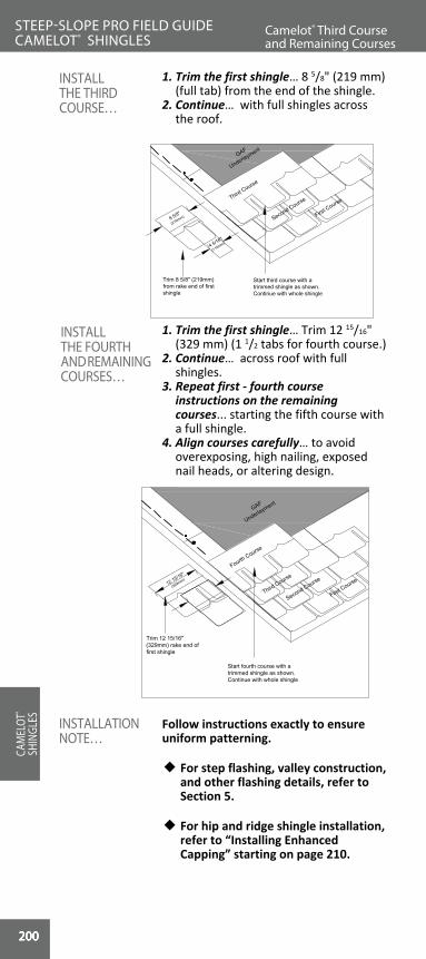
200
CAMELOT
® SHINGLES
200
ROO
FIN
G
BASI
CSSTEEP-SLOPE PRO FIELD GUIDE CAMELOT® SHINGLES
CAM
ELOT
® SH
INGL
ES
1. Trim the first shingle… 8 5/8" (219 mm) (full tab) from the end of the shingle.
2. Continue… with full shingles across the roof.
1. Trim the first shingle… Trim 12 15/16" (329 mm) (1 1/2 tabs for fourth course.)
2. Continue… across roof with full shingles.
3. Repeat first - fourth course instructions on the remaining courses... starting the fifth course with a full shingle.
4. Align courses carefully… to avoid overexposing, high nailing, exposed nail heads, or altering design.
Follow instructions exactly to ensure uniform patterning.
w For step flashing, valley construction, and other flashing details, refer to Section 5.
w For hip and ridge shingle installation, refer to “Installing Enhanced Capping” starting on page 210.
INSTALLTHE FOURTH AND REMAINING COURSES…
INSTALLATION NOTE…
INSTALL THE THIRD COURSE…
Camelot® Third Course and Remaining Courses
First Course
Second CourseThird Course
4 5/16"
(110mm)
8 5/8"
(219mm)
Trim 8 5/8" (219mm)from rake end of firstshingle
GAF
Underlayment
Start third course with atrimmed shingle as shown.Continue with whole shingle
First Course
Second Course
Third Course12 15/16"
(329mm)
Fourth Course
Trim 12 15/16"(329mm) rake end offirst shingle
GAF
Underlayment
Start fourth course with atrimmed shingle as shown.Continue with whole shingle
200200

ROO
FING
BA
SICS
201
1. True or False? A trimmed Camelot® Shingle or full piece of WeatherBlocker™ Premium Eave/Rake Starter Strip can be used as a starter course to install Camelot® Shingles.
A. True B. False
2. What is the correct number of fasteners for Camelot® Shingles?
A. 4 B. 5 C. 6 D. 7
3. What is the correct hip and ridge cap shingle for use with Camelot® Shingles?
A. Timberline® Shingles. B. Royal Sovereign® Shingles. C. Slateline® Shingles D. None of the above.
4. How many courses are run before starting again with a full shingle?
A. 4 B. 5 C. 6 D. 7
5. Because of Camelot’s heavyweight construction and detailed design, the preferred valley method is: (Hint: See Valley Construction Section)
A. Woven valley. B. Open valley. C. Closed cut valley. D. All of the above.
REVIEW #17STEEP-SLOPE PRO FIELD GUIDE Camelot® Third Course and Remaining Courses
CAMELOT
® SHINGLES

202
MONACO
® SHINGLES
202
ROO
FIN
G
BASI
CSCA
MEL
OT®
SHIN
GLES
202202202
NOTES
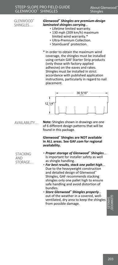
203
Glenwood™ Shingles are premium-design laminated shingles carrying… • Lifetime limited warranty. • 130 mph (209 km/h) maximum
limited wind warranty.* • Ultra-Premium Collection. • StainGuard® protection.
* In order to obtain the maximum wind coverage, the shingles must be installed using certain GAF Starter Strip products (only those with factory-applied adhesive) on the eaves and rakes. Shingles must be installed in strict accordance with published application instructions, particularly in regard to nail placement.
Note: Shingles shown in drawings are one of 6 different design patterns that will be found in this package.
Glenwood™ Shingles are NOT available in ALL areas. See GAF.com for regional availability.
• Proper storage of Glenwood™ Shingles... is important for installer safety as well as shingle handling.
• For best results, stack one pallet high... Due to the heavyweight construction and detailed design of Glenwood™ Shingles, GAF recommends stacking shingles only one pallet high to ensure safe handling and avoid distortion of bundles.
• Store Glenwood™ Shingles properly… out of the weather in a covered, well-ventilated, dry area to keep the shingles from possible damage.
AVAILABILITY…
STACKING AND STORAGE…
GLENWOOD™
SHINGLES…
About Glenwood™Series Shingles
STEEP-SLOPE PRO FIELD GUIDE GLENWOOD™ SHINGLES
(311 mm)
(922 mm)36 5/16"
12 1/4"
GLENWOOD
™ SHINGLES

204
SLATELINE®
SHINGLES
204
STEEP-SLOPE PRO FIELD GUIDE GLENWOOD™ SHINGLES
GLEN
WOO
D™ SH
INGL
ES
w Two starter courses are needed to fill out Glenwood™ Shingles’ extra width and thickness.
w First Starter Course… Split GAF WeatherBlocker™ Premium Eave/Rake Starter Strip into ½ height pieces 8.5" x 40" (216 x 1,016 mm) and install along the eaves.
Overhang starter strip shingles… ¼''-¾" (6-19 mm) over the drip edge at both rakes and eaves to keep water away from the structure.
w Second Starter Course… Install full-height GAF WeatherBlocker™ Starter Strips. Do NOT split second starter course strips in half.
INSTALLING STARTER COURSE…
Glenwood™ Shingle Starter Course
204
INSTALL THE FIRST STARTER COURSE…

205
ROO
FING
BA
SICSSTEEP-SLOPE PRO FIELD GUIDE GLENWOOD™ SHINGLES
Glenwood™ Shingle Starter Course
Glenwood™ Shingle Starter Course
GLENWOOD
™ SHINGLES
INSTALLING THE SECOND STARTER COURSE…
1. Trim 30" (762 mm) off of rake edge of first WeatherBlocker™ Starter Strip Shingle to ensure the first course overlaps the seam.
2. Continue with full-size starter strip shingle.
3. Place second starter directly over first starter… to give the correct depth to the starter course.
4. Align second starter even with first at the rakes and eaves.
5. Nail second starter… 1 ½" – 3" (38-76 mm) above butt edge of shingle.

206
SLATELINE®
SHINGLES
206
STEEP-SLOPE PRO FIELD GUIDE GLENWOOD™ SHINGLES
GLEN
WOO
D™ SH
INGL
ES
1. Start with full shingle… • Install flush with starter course. • Install left to right or right to left.2. Use four fasteners… The standard
pattern is four fasteners. See “Standard Nailing Pattern” below.
3. Use six fasteners if required… the alternate pattern is six fasteners if required by local code or for enhanced warranty. See “Enhanced Nailing Pattern” below.
4. Fasten along the nail guide marks… nominally 8 1/2" (216 mm) from bottom of shingle.
5. Continue across the roof... in the same manner.
HOW TO INSTALL THE FIRST COURSE…
Glenwood™ Starter and First Course
(311 mm)
(922 mm)
(13 - 64 mm)1/2" - 2 1/2"
(13 - 64 mm)1/2" - 2 1/2"
(279 - 333 mm)(279 - 333 mm)
Self-sealadhesive onback
Alignment slits
11" - 13"
36 5/16"
12 1/4"11" - 13"
(13 - 64 mm)1/2" - 2 1/2"
(13 - 64 mm)1/2" - 2 1/2"
(349 - 400 mm) (349 - 400 mm)
(229 -279 mm)
36 5/16"
12 1/4"
13 3/4" - 15 3/4"
9" - 11"
13 3/4" - 15 3/4"
9" - 11"
Self-sealadhesive onback
Alignment slits
(229 -279 mm)
(922 mm)
(311 mm)
206
Standard Nailing Pattern - Four nails per shingle
Enhanced Nailing Pattern - Six nails per shingle*
* Required by some local codes and required for enhanced wind coverage on certain products. See limited warranty for details..

207
ROO
FING
BA
SICSSTEEP-SLOPE PRO FIELD GUIDE GLENWOOD™ SHINGLES
w Do NOT lay Glenwood™ Shingles straight up the roof, as this procedure can cause an incorrect color blend and may dam-age the shingles as well.
1. Trim the second shingle… 6" (152 mm) (1/2 of a tab) from the end of the shingle.
2. Position the shingles in the second and subsequent courses flush... with the tops of the wide cut-outs. This results in a 4 1/2" (114 mm) exposure.
3. Continue with full shingles… across the roof. Strike a chalk line every few courses to ensure alignment.
INSTALLATION NOTE: RACKING
INSTALLTHE SECOND COURSE…
INSTALL THE FIRST COURSE…
Glenwood™ First and Second Course
Glenwood™ Starter and First Course
GLENWOOD
™ SHINGLES

208
GLENWOO
D™ SHINGLES
208
ROO
FIN
G
BASI
CSSTEEP-SLOPE PRO FIELD GUIDE GLENWOOD™ SHINGLES
GLEN
WOO
D™ SH
INGL
ES
1. Trim the third shingle… 12" (305 mm) from the end of the shingle.
2. Continue… with full shingles across the roof.
1. Trim the fourth shingle… Trim 18" (457 mm) from the end of the shingle.
2. Continue… across roof with full shingles.
3. Repeat first through fourth course instructions on the remaining courses... starting the fifth course with a full shingle.
4. Align courses carefully… to avoid overexposing, high nailing, exposed nail heads, or altering design.
Follow instructions exactly to avoid objectional patterning.
w For step flashing, valley construction, and other flashing details, refer to Section 5.
w For hip and ridge shingle installation, refer to “Installing Enhanced Capping” starting on pages 210-220.
INSTALLTHE FOURTH AND REMAINING COURSES…
INSTALLATION NOTE…
INSTALL THE THIRD COURSE…
Glenwood™ Third Course and Remaining Courses
208208

ROO
FING
BA
SICS
209
1. True or False? A trimmed Glenwood™ Shingle can be used as a starter course to install Glenwood™ Shingles.
A. True B. False
2. What is the correct number of fasteners for the stan-dard nailing pattern for Glenwood™ Shingles?
A. 4 B. 5 C. 6 D. 7
3. What is the correct hip and ridge cap shingle for use with Glenwood™ Shingles?
A. Timberline® Shingles. B. Royal Sovereign® Shingles. C. Slateline® Shingles D. None of the above.
4. How many courses are run before starting again with a full shingle?
A. 4 B. 5 C. 6 D. 7
5. Because of Glenwood’s™ heavyweight construction and detailed design, the preferred valley method is: (Hint: See Valley Construction Section)
A. Woven valley. B. Open valley. C. Closed cut valley. D. All of the above.
REVIEW #18STEEP-SLOPE PRO FIELD GUIDE Glenwood™ Third Course and Remaining Courses
GLENWOOD
™ SHINGLES

210
GLENWOO
D™ SHINGLES
GLENWOO
D™ SHINGLES
MONACO
® SHINGLES
210
w Professionals match the Ridge Cap Shingles to the roof… Using Ridge Cap Shingles that do not match the field shingle looks unprofessional and is a disservice to the customer.
Protective Ridge Cap Shingles… • Offer enhanced protection and
warranty coverage (vs. using cut-up strip shingles as Ridge Caps).
• Enhance the look of the finished roof.
• Properly complement the field shingle color.
w Five specially designed Ridge Cap Shingles… to match GAF shingles, GAF manufactures five special protective Ridge Cap Shingles:
• Timbertex® Premium Ridge Cap Shingles.
• Ridglass® Premium Ridge Cap Shingles.
• Z® Ridge Ridge Cap Shingles. • Seal-A-Ridge® Ridge Cap Shingles. • Seal-A-Ridge® ArmorShield™ Ridge
Cap Shingles. Note: All of these enhanced ridge cap shingles count as a single eligible accessory on Weather Stopper® System Plus Limited Warranty installations.
GAF SHINGLE INSTALLED
CORRESPONDING GAF RIDGE CAP PRODUCTS
Royal Sovereign®
• Royal Sovereign® Shingles
• Marquis Weather-Max® Shingles
• Any Ridge Cap listed above
Marquis WeatherMax®
• Marquis Weather-Max® Shingles
• Any Ridge Cap listed above
All Other Shingles
• Timbertex® Ridge Cap Shingles
• Ridglass® Ridge Cap Shingles
• Z® Ridge Ridge Cap Shingles
• Seal-A-Ridge® Ridge Cap Shingles/ Seal-A-Ridge® ArmorShield™ Ridge Cap Shingles
All GAF Ridge Cap products are acceptable on Weather Stopper®
Golden Pledge® and Silver Pledge® installations.
ROO
FIN
G
BASI
CS
ENHANCED HIP AND RIDGE CAP SHINGLES…
WEATHER STOPPER® GOLDEN PLEDGE® AND SILVER PLEDGE® NOTE…
Enhanced Ridge Cap Shingles
STEEP-SLOPE PRO FIELD GUIDE INSTALLING ENHANCED CAPPING
INST
ALLIN
G EN
HANC
ED
CAPP
ING
210210210

1. Install at ridge with the prevailing wind… To gain maximum wind resis-tance, install so dominant winds flow over the hip and ridge shingles along the ridge.
2. Use correct-length roofing nails… long enough to penetrate at least 3/4" (19 mm) into wood decks or just through plywood or OSB.
3. Separate each piece of Timbertex® Ridge Cap Shingle… into three indi-vidual Ridge Cap Shingle pieces at pre-scored perforations (see Figure 1).
4. Prepare the starter course... Use a 12" x 12" (305 mm x 305 mm) ridge cap piece and cut along the line between the headlap and exposed area of the shingle. This will provide a double-thick 4" x 11 1/2" (102 mm x 292 mm) starter piece (see Figure 2).
5. Install the 4" x 11 1/2" (102 mm x 292 mm) double-thick starter cap across the hip or ridge... starting at the bot-tom of the hip or at the end of the ridge opposite the direction of the prevailing wind.
INSTALLING TIMBERTEX® PREMIUM RIDGE CAP SHINGLES… RO
OFIN
G
BASICS
Timbertex® Premium Ridge Cap Shingles
STEEP-SLOPE PRO FIELD GUIDE INSTALLING ENHANCED CAPPING
Figure 1
Figure 2
211
GLENWOO
D™ SHINGLES
GLENWOO
D™ SHINGLES
Enhanced Ridge Cap Shingles
INSTALLING ENHANCED
CAPPING

212212
6. Begin laying full Ridge Cap Shingle pieces 12" x 12" (305 x 305 mm)… as shown (see Figure 3). Apply with an 8" (203 mm) exposure beginning at the bottom of the hip or from the end of the ridge, opposite the direction of the prevailing wind. The inner edge of the 4" (102 mm) wide laminated piece provides alignment for the next unit.
7. Apply Ridge Cap using 2 nails per piece 9" (229 mm) back from the ex-posed end and 1" (25 mm) up from the edge… (see Figure 3 for location of nails). Use only zinc-coated steel or aluminum, 10-12 gauge, barbed, deformed, or smooth shank roofing nails with heads 3/8" (10 mm) to 7/16" (12 mm) in diam-eter. Nails should be long enough to penetrate at least 3/4" (19 mm) into wood decks or just through plywood or OSB decks. Nails must be driven flush with the surface of the shingle. Overdriving will damage the shingle. Raised nails will interfere with the wind resistance of the shingles.
8. Install last piece by: • Setting the last piece… in solid
troweling of asphalt plastic roof cement (must conform to ASTM D4586 Type I or Type 2), or
• Face nailing the last piece… and sealing the nail head with asphalt plastic cement.
ROO
FIN
G
BASI
CSTimbertex® Premium Ridge Cap Shingles
STEEP-SLOPE PRO FIELD GUIDE INSTALLING ENHANCED CAPPING
Figure 3
MONACO
® SHINGLES
212
INST
ALLIN
G EN
HANC
ED
CAPP
ING
212212212

Figure 4
9. In order to obtain the maximum wind speed coverage under GAF Limited Warranties… you MUST apply a 1/4" (6 mm) wide bead of Henkel PL® Urethane Sealant or Soneborne® NP-1™ Urethane Sealant to each Ridge Cap Shingle 3/4"-1" (19-25 mm) from the shingle edge, parallel to the ridge (see Figure 4) before setting the next shingle in place.
For cold weather application... Warm Timbertex® Ridge Cap Shingles before bending. When self-sealing may be de-layed due to cold weather, apply quarter-sized dabs of asphalt plastic cement (must conform to ASTM D4586 Type I or Type II) between Ridge Cap pieces and press firmly to ensure good contact between pieces.
w Caution: Excessive application of cement can cause blistering of Ridge Cap Shingles.
ROO
FING
BA
SICSTimbertex® Premium Ridge Cap Shingles
STEEP-SLOPE PRO FIELD GUIDE INSTALLING ENHANCED CAPPING
213
STEEP-SLOPE PRO FIELD GUIDE INSTALLING ENHANCED CAPPING
Timbertex® Premium Ridge Cap Shingles
INSTALLING ENHANCED
CAPPING
SPECIAL APPLICATION…

214214
1. Install Z® Ridge ridge cap shingles at ridge with the prevailing wind… To gain maximum wind resistance, install so dominant winds flow over the hip and ridge shingles along the ridge.
2. Use correct-length roofing nails… long enough to penetrate at least 3/4" (19 mm) into wood decks or just through plywood or OSB.
3. Separate hip and ridge shingles into individual shingles… each 13 1/4 x 39 3/8" (337 x 1000 mm) strip is scored for separation into four hip or ridge shingles with exposure to be 5 5/8" (143 mm).
4. Create a starter cap shingle… by cutting shingle and folding on fold lines. (See Figures 1-3.)
ROO
FIN
G
BASI
CS
INSTALLING Z® RIDGE RIDGE CAPSHINGLES…
Z® Ridge Ridge Cap Shingles
STEEP-SLOPE PRO FIELD GUIDE INSTALLING ENHANCED CAPPING
Perforation
9 7/8"(251 mm)
13 1/4"(337 mm)
39 3/8" (1 m)
Figure 1
Figure 2
MONACO
® SHINGLES
214
INST
ALLIN
G EN
HANC
ED
CAPP
ING
214214214

5. Nail starter cap shingle… one nail on each side 1" (25 mm) in from each edge through triple fold area.
6. Fold each hip and ridge shingle… as shown in Figures 4-6 (see also next page).
ROO
FING
BA
SICSZ® Ridge Ridge Cap Shingles
STEEP-SLOPE PRO FIELD GUIDE INSTALLING ENHANCED CAPPING
Figure 3
Figure 4
215
Z® Ridge Ridge Cap Shingles
INSTALLING ENHANCED
CAPPING
Figure 5

216216
7. Bend to conform to ridge or hip...for best appearance and wind resistance.
8. Install hip and ridge shingles… with maximum overhang of 1/4" to 3/8" (6-10 mm) and 5 5/8" (143 mm) exposure.
9. Nail… with one nail on each side through triple fold area on nail line 6 1/2" (165 mm) from butt edge and 1" (25 mm) from each side (see above).
10. Install last piece by face nailing… and sealing the nail heads with asphalt plastic cement.
11. For maximum wind resistance and in order to obtain enhanced wind warranties… apply quarter-sized dabs of asphalt plastic cement on each side of hip or ridge 1" (25 mm) in and 1" (25 mm) up under the leading butt corners.
For cold weather application... Warm Z-Ridge® Ridge Cap Shingles before bending. When self-sealing may be delayed due to cold weather, apply
Z® Ridge Ridge Cap Shingles
STEEP-SLOPE PRO FIELD GUIDE INSTALLING ENHANCED CAPPING
Figure 6
MONACO
® SHINGLES
216
INST
ALLIN
G EN
HANC
ED
CAPP
ING
216216216
SPECIAL APPLICATION…
Figure 7

Installing Seal-A-Ridge® and Seal-A-Ridge® ArmorShield™ Ridge Cap Shingles…
1. Install at ridge with the prevailing wind… To gain maximum wind resistance, install so dominant winds flow over the hip and ridge shingles along the ridge.
2. Use correct-length roofing nails… long enough to penetrate at least 3/4" (19 mm) into wood decks or just through plywood or OSB.
3. Separate hip and ridge shingles into individual shingles... At perforations, separate each piece into three indi-vidual Ridge Cap Shingles, each 12" x 12" (305 mm x 305 mm).
4. Create a starter shingle by... cutting off the exposed portion of a ridge cap shingle.
5. Beginning at the bottom of the hip or at the end of the ridge opposite the di-rection of the prevailing wind... Install the starter shingle using 2 nails placed 1 1/2" -3" (38-76 mm) back from the cut end and 1"-2" (25 -51 mm) up from each edge.
6. Apply individual ridge cap shingle pieces... completely covering the starter shingle with the first full ridge cap shingle.
INSTALLINGSEAL-A- RIDGE® RIDGE CAP SHINGLES…
Z® Ridge and Seal-A-Ridge® Ridge Cap Shingles
STEEP-SLOPE PRO FIELD GUIDE INSTALLING ENHANCED CAPPING
217
Cut5" (127 mm) forSeal-A-Ridge® AmorShield™
Ridge Cap Shingles
12"
11.5"(292 mm)
6 2/3" (169 mm) forSeal-A-Ridge® RidgeCap Shingles
Z® Ridge Ridge Cap Shingles
INSTALLING ENHANCED
CAPPING
quarter-sized dabs of asphalt plastic cement (must conform to ASTM D4586 Type I or Type II) at the two exposed cor-ners 1" (25 mm) in and 1" (25 mm) up between ridge cap pieces. Press firmly to ensure good contact between pieces.
w Caution: Excess amount of cement can cause blistering on the shingles.
Figure 1

218
5"(127 mm)
6" - 6 1/2"
(152 - 165 mm)
1" - 2"
(25 - 52 mm)
6 2/3"(169 mm)
7" - 7 5/8"
(178 - 194 mm)
1" - 2"
(25 - 52 mm)
218
• For Seal-A-Ridge® ArmorShield Ridge Cap Shingles leave a 5” (127 mm) exposure.
• For Seal-A-Ridge® Ridge Cap Shingles leave a 6-2/3” (169 mm) exposure.
7. Apply ridge cap using 2 nails per piece. Do NOT nail through sealant.
• For Seal-A-Ridge® ArmorShield Ridge Cap Shingles 6" – 6 1/2" (152 - 165 mm) back from the exposed end and 1"-2" (25 - 51 mm) up from the edge (see Figure 2).
• For Seal-A-Ridge® Ridge Cap Shingles 7" – 7 5/8" (178 - 194 mm) back from the exposed end and 1"-2" (25 - 51 mm) up from the edge (see Figure 3).
8. Install last piece by: • Setting the last piece… in solid
troweling of asphalt plastic roof cement, or
• Face-nailing the last piece… and sealing the nail heads with asphalt plastic cement.
ROO
FIN
G
BASI
CSSeal-A-Ridge® Ridge Cap Shingles
STEEP-SLOPE PRO FIELD GUIDE INSTALLING ENHANCED CAPPING
MONACO
® SHINGLES
218
INST
ALLIN
G EN
HANC
ED
CAPP
ING
218218218
Figure 2
Figure 3

Installing Ridglass® Premium Ridge Cap Shingles…1. Install at ridge with the prevailing
wind… To gain maximum wind resistance, install so dominant winds flow over the hip and ridge shingles along the ridge.
2. Use correct-length roofing nails… long enough to penetrate at least 3/4" (19 mm) into wood decks or just through plywood or OSB.
3. Create a starter cap shingle… by cut-ting off the 8" (203 mm) exposed por-tion of a full hip and ridge shingle.
4. Beginning at the bottom of the hip or at the end of the ridge opposite the direction of the prevailing wind… with one nail on each side 1" (25 mm) in and 1" (25 mm) up on the leading corner.
5. Cover starter cap shingle… with com-plete hip and ridge shingle extending 1/4" (6 mm) over the starter shingle.
6. Nail through the dimensional fold… with one nail on each side of the starter shingle 9" (229 mm) back from the exposed end and 1" (25 mm) in from each side.
7. Continue installing hip and ridge shingles… extending 1/4" (6 mm) past the dimensional fold to obtain a 8" (203 mm) exposure.
Note: For hips, starter cap shingle must be tapered to conform to the point of the hip.
INSTALLING RIDGLASS® PREMIUM RIDGE CAP SHINGLES… RO
OFIN
G
BASICS
Ridglass® Premium Ridge Cap Shingles
STEEP-SLOPE PRO FIELD GUIDE INSTALLING ENHANCED CAPPING
219
Seal-A-Ridge® Ridge Cap Shingles
INSTALLING ENHANCED
CAPPING

220220
8. Install last piece… by setting the last piece in solid troweling of asphalt plastic roof cement.
9. For maximum wind resistance and in order to obtain enhanced wind warranties… apply three quarter-sized dabs of asphalt plastic ce-ment on each side of hip and ridge shingle and install with four nails per shingle as shown below.
10. In cold weather… under 50oF (10oC), unpack shingles from carton and allow the shingles to warm before application.
For cold weather application... Warm Z-Ridge® Premium Ridge Cap Shingles before bending. When self-sealing may be delayed due to cold weather, apply quarter-sized dabs of asphalt plastic cement (must conform to ASTM D4586 Type I or Type II) at the two exposed corners 1" (25 mm) in and 1" (25 mm) up between ridge cap pieces. Press firmly to ensure good contact between pieces.
w Caution: Excess amount of cement can cause blistering of Ridge Cap Shingles.
ROO
FIN
G
BASI
CSRidglass® Premium Ridge Cap Shingles
STEEP-SLOPE PRO FIELD GUIDE INSTALLING ENHANCED CAPPING
MONACO
® SHINGLES
220
INST
ALLIN
G EN
HANC
ED
CAPP
ING
220220220
SPECIAL APPLICATION…

1. Matching the Ridge Cap Shingle to the field shingle installed on the roof does which of the following?
A. Properly complements the shingle color. B. Enhances the look of the finished roof. C. Matches the starter strip. D. Both A and B.
2. True or False? Starting at the end opposite the prevailing wind will insure the air flow is over the Ridge Caps, not against them.
A. True B. False
3. How much thicker than standard cap shingles is a Timbertex® Premium Ridge Cap Shingle?
A. 2 times. B. 3 times. C. 4 times. D. Twice as thick.
4. What are the proper nail locations for Timbertex® Distinctive Ridge Cap Shingles?
A. 3" (76 mm) from the edge. B. 2" (51 mm) from the edge, 8" (203 mm) from the
bottom. C. 1" (25 mm) from the edge, 9" (228 mm) from the
bottom. D. 4" (102 mm) from the edge, 7" (178 mm) from the
bottom.
5. True or False? GAF Timbertex®, Z®Ridge, and Seal-A-Ridge® Ridge Cap Shingles are accepted on Golden and Silver Pledge® Ltd. Warranty installations.
A. True B. False
ROO
FING
BA
SICSREVIEW #19STEEP-SLOPE PRO FIELD GUIDE
221
Ridglass® Premium Ridge Cap Shingles
INSTALLING ENHANCED
CAPPING

222
INSTALLING ENHANCED CAPPING
222
1. Not all valley constructions are appropriate… for use with all shingles (e.g., woven valleys should not be installed using laminated shingles).
2. Choose correct valley… see chart below.
USE CORRECT VALLEY CON- STRUCTIONS…
Choosing The Correct Valley Construction
STEEP-SLOPE PRO FIELD GUIDE INSTALLING SHINGLE VALLEYS
INST
ALLIN
G SH
INGL
E VAL
LEYS
APPROPRIATE VALLEY CONSTRUCTIONS
SHINGLE OPEN VALLEY
CLOSED CUT
VALLEY
WOVEN VALLEY
OPEN CALIFORNIA
VALLEY
CLOSED CUT
CALIFORNIA VALLEY
Marquis WeatherMax® YES YES YES NO NO
Royal Sovereign® YES YES YES NO NO
Timberline® Natural
Shadow®YES YES NO
Limited* (Mini-mum slope 4:12)
Yes (Minimum
slope 4:12)
Timberline®
Cool Series YES YES NO
Limited* (Mini-mum slope 4:12)
Yes (Minimum
slope 4:12)
Timberline®
American Harvest®
YES YES NO
Limited* (Mini-mum slope 4:12)
Yes (Minimum
slope 4:12)
Timberline® ArmorShield™
IIYES YES NO
Limited* (Mini-mum slope 4:12)
Yes (Minimum
slope 4:12)
TimberlineUltra HD® YES YES NO
Limited* (Mini-mum slope 4:12)
Yes (Minimum
slope 4:12)
Woodland® YES YES NO NO NO
Sienna® YES YES NO NO NO
GrandSequoia® & Grand Sequoia®
ArmorShield™
YES YES NO NO NO
Grand Canyon® YES YES NO NO NO
Slateline® YES YES YES NO NO
Camelot® II YES YES NO NO NO
Camelot® YES NO NO NO NO
Glenwood™ YES NO NO NO NO
* Not permitted for Weather Stopper® Golden and Silver Pledge® Limited Warranty.
222222222222222
INSTALLING ENHANCED CAPPING
INSTALLING ENHANCED CAPPING

1. Install GAF Leak Barrier… full 36" (914 mm) wide over entire valley length.
2. Lap Deck-Armor® or any other GAF Roof Deck Protection 6" (152 mm)… over the Leak Barrier.
3. Center the valley metal… Use metal proven to last.
• 20" (508 mm) min. wide aluminum, galvanized steel or copper. Note: Local building codes may require wider metal in open valley constructions.
• Non-corroding, non-staining metal. • 24-gauge minimum.4. Nail the metal on the edges… Place
nails so the nail heads hold the metal in place.
5. Do NOT puncture the metal… Nailing through the metal may cause leaking and buckling due to movement.
6. Install shingles into the valley… Cover the metal 4” (102 mm) to 12” (305 mm) for sealing.
7. Clip the corners… to keep water flow toward the valley center.
8. Taper valley shingles… to handle increasing water volume.
• Start with minimum shingle separation of 6" (152 mm)… at the valley top.
• Widen shingle separation 1/8” (3 mm) per 1 foot (305 mm)… toward the eave.
9. Embed shingle ends in plastic roof cement… Seal shingles to the metal to keep water from running under them. (Note: Excess cement can cause shingle blisters.)
Required procedure for Weather Stopper® Golden Pledge® and Silver Pledge® installations is to follow all of the steps above.
WEATHER STOPPER® GOLDEN PLEDGE® AND SILVER PLEDGE® NOTE…
OPEN VALLEYS…
ROO
FING
BA
SICSOpen Valley Installation
STEEP-SLOPE PRO FIELD GUIDE INSTALLING SHINGLE VALLEYS
223
OPEN VALLEY INSTALLATION…
Choosing The Correct Valley Construction
INSTALLING SHINGLE VALLEYS

224
INSTALLING SHINGLE VALLEYS
224
ROO
FIN
G
BASI
CSClosed Cut Valley Installation
STEEP-SLOPE PRO FIELD GUIDE INSTALLING SHINGLE VALLEYS
INST
ALLIN
G SH
INGL
E VAL
LEYS
1. Install GAF Leak Barrier… full 36" (914 mm) wide over entire valley length.
2. Lap Deck-Armor® or any other GAF Roof Deck Protection 6" (152 mm)… over the Leak Barrier.
3. Install one roof plane over the other… with the larger roof plane over the smaller to keep large water flow over the valley cut.
4. Extend starters and first course across valley… Both right and left starter courses should extend 12" (30 mm) min. beyond the center line.
5. Fasten properly in valley… • No nails within 6" (152 mm) of the
valley center to reduce potential leaks.
• Double nail shingle ends in valley to compensate for this 6" (152 mm) space.
6. Continue up the valley… • Installing underlying shingles 12"
(305 mm) min. past the valley center line.
• Leave top shingles extended past the center line to be cut later.
7. Trim shingles… 2" (51 mm) back from valley center line on top roof plain.
8. Clip shingle corners… Clip shingle cor-ners at the valley to keep water flow to the valley center.
9. Seal the valley… Using plastic roof cement, seal the valley shingles to each other for the best protection. Note: Too much cement can cause shingles to blister.
Required procedure for Weather Stopper® Golden Pledge® and Silver Pledge® installations is to follow all of the steps above.
WEATHER STOPPER® GOLDEN PLEDGE®
AND SILVER PLEDGE® NOTE…
CLOSED CUT VALLEYS…
CLOSED CUT VALLEY INSTALLATIONS…
6"(152 mm)
6"(152 mm)
Carry GAF underlaymentat least 6" (152mm) overGAF leak barrier.
Center full width roll ofGAF leak barrier.Do not place fastenerswithin 6" (152mm) ofcenter line. Horizontallaps must be at least 6"(152mm).
Extend end ofshingle at least 12"
(305mm)beyond valley
center line. Nail,putting extra
fastener in topcorner of shingle.
Extend starter stripacross valleyat least 12" (305mm)and weave withopposite side starterstrip shingle.
Overlying shinglesmust be cut so they
are 2" (52mm) awayfrom valley center
line. Clip shinglecorners 45° to keep
water flow in thevalley center. Seal
the valley shingles toeach other using
asphalt plasticcement.
224224224224224224
INSTALLING SHINGLE VALLEYS
INSTALLING SHINGLE VALLEYS

225
1. Install GAF Leak Barrier… full 36" (914 mm) wide over entire valley length.
2. Lap Deck-Armor® or any other GAF Roof Deck Protection 6" (152 mm)… over the Leak Barrier.
3. Carry both shingle courses to the valley.
4. Weave the shingles… Install one shingle over the other as you go up the valley.
5. Extend each shingle end 12" (305 mm) min… beyond the valley center.
6. Seat the shingles in the valley… Before nailing, firmly press shingles down at valley center to conform to valley shape.
7. Do NOT nail closer than 6" (152 mm) to valley center… Due to the extreme water volume in valleys, nails near the center can leak.
8. Nail twice at shingle ends… Instead of nailing in valley center, nail twice at the ends.
9. Keep valley centered… Allowing the weave to creep up a valley side will allow water infiltration under the shingles.
w Caution: For single-thickness
shingles only; see Acceptable Valley Constructions Chart on page 222.
WOVEN VALLEYS…
ROO
FING
BA
SICSWoven Valley Installation
STEEP-SLOPE PRO FIELD GUIDE INSTALLING SHINGLE VALLEYS
WOVEN VALLEY INSTALLATIONS…
Closed Cut Valley Installation
INSTALLING SHINGLE VALLEYS
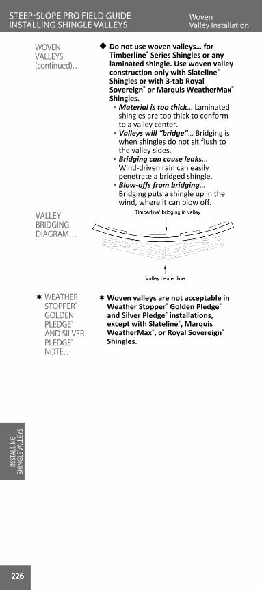
226
INSTALLING SHINGLE VALLEYS
226
w Do not use woven valleys… for Timberline® Series Shingles or any laminated shingle. Use woven valley construction only with Slateline® Shingles or with 3-tab Royal Sovereign® or Marquis WeatherMax® Shingles.
• Material is too thick… Laminated shingles are too thick to conform to a valley center.
• Valleys will “bridge”… Bridging is when shingles do not sit flush to the valley sides.
• Bridging can cause leaks… Wind-driven rain can easily penetrate a bridged shingle.
• Blow-offs from bridging… Bridging puts a shingle up in the wind, where it can blow off.
Woven valleys are not acceptable in Weather Stopper® Golden Pledge® and Silver Pledge® installations, except with Slateline®, Marquis WeatherMax®, or Royal Sovereign® Shingles.
ROO
FIN
G
BASI
CS
VALLEY BRIDGING DIAGRAM…
WEATHER STOPPER® GOLDEN PLEDGE® AND SILVER PLEDGE® NOTE…
WOVEN VALLEYS (continued)…
Woven Valley Installation
STEEP-SLOPE PRO FIELD GUIDE INSTALLING SHINGLE VALLEYS
INST
ALLIN
G SH
INGL
E VAL
LEYS
226226226226226226226
INSTALLING SHINGLE VALLEYS
INSTALLING SHINGLE VALLEYS
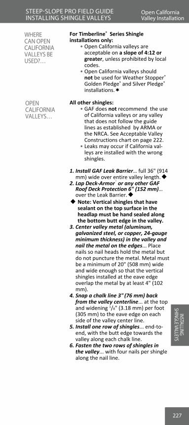
227
For Timberline® Series Shingle installations only: • Open California valleys are
acceptable on a slope of 4:12 or greater, unless prohibited by local codes.
• Open California valleys should not be used for Weather Stopper® Golden Pledge® and Silver Pledge® installations.
All other shingles: • GAF does not recommend the use
of California valleys or any valley that does not follow the guide lines as established by ARMA or the NRCA. See Acceptable Valley Constructions chart on page 222.
• Leaks may occur if California val-leys are installed with the wrong shingles.
1. Install GAF Leak Barrier… full 36" (914 mm) wide over entire valley length.w
2. Lap Deck-Armor® or any other GAF Roof Deck Protection 6" (152 mm)… over the Leak Barrier.w w Note: Vertical shingles that have
sealant on the top surface in the headlap must be hand sealed along the bottom butt edge in the valley.
3. Center valley metal (aluminum, galvanized steel, or copper, 24-gauge minimum thickness) in the valley and nail the metal on the edges... Place nails so nail heads hold the metal but do not puncture the metal. Metal must be a minimum of 20" (508 mm) wide and wide enough so that the vertical shingles installed at the eave edge overlap the metal by at least 4" (102 mm).
4. Snap a chalk line 3" (76 mm) back from the valley centerline... at the top and widening 1/8" (3.18 mm) per foot (305 mm) to the eave edge on each side of the valley center line.
5. Install one row of shingles... end-to-end, with the butt edge towards the valley along each chalk line.
6. Fasten the two rows of shingles in the valley... with four nails per shingle along the nail line.
OPEN CALIFORNIA VALLEYS…
WHERE CAN OPEN CALIFORNIA VALLEYS BE USED?… RO
OFIN
G
BASICS
Open California Valley Installation
STEEP-SLOPE PRO FIELD GUIDE INSTALLING SHINGLE VALLEYS
Woven Valley Installation
INSTALLING SHINGLE VALLEYS

228
INSTALLING SHINGLE VALLEYS
228
7. When using an open California valley, start shingle installation from the valley and work towards each rake edge. Position each shingle starting a course with the tip of the shingle at the butt edge of the vertically installed shingle. Fasten shingles as usual with the exception of staying 6" (152 mm) away from the valley center-line. Start the first course with a full-length shingle; the second course with enough trimmed off of the shingle to maintain a 6" (152 mm) offset from the first course; the third course trimmed to maintain 5" (127 mm) offset from the second course; the fourth course trimmed to maintain a 6" (152 mm) offset from the third course; and the fifth course should start the pattern over again with a full shingle.
Open California valleys are not accepted on WeatherWatch® Golden Pledge® and Silver Pledge® installations.
ROO
FIN
G
BASI
CS
WEATHER STOPPER® GOLDEN PLEDGE® AND SILVER PLEDGE® NOTE…
Open California Valley Installation
STEEP-SLOPE PRO FIELD GUIDE INSTALLING SHINGLE VALLEYS
INST
ALLIN
G SH
INGL
E VAL
LEYS
228228228228228228228228
INSTALLING SHINGLE VALLEYS
INSTALLING SHINGLE VALLEYS

229
For Timberline® Series Shingle installations only: • Closed cut California valleys are
acceptable on a slope of 4:12 or greater, unless prohibited by local codes.
All other shingles: • GAF does not recommend the use
of California valleys or any valley that does not follow the guide lines as established by ARMA or the NRCA. See Acceptable Valley Constructions chart on page 222.
• Leaks may occur if California valleys are installed with the wrong shingles.
1. Install GAF Leak Barrier… full 36" (914 mm) wide over entire valley length.
2. Lap Deck-Armor® or any other GAF Roof Deck Protection 6" (152 mm)… over the Leak Barrier.
3. Install starter shingles and the shingles on the lower slope or lesser height... Extend the end shingle of each course at least 12" (305 mm) onto the adjoining roof.
4. Press shingles into the valley and nail as directed on the bundle... with the exception that no nails are within 6" (152 mm) of the valley centerline.
5. Additional fasteners... place two nails at the end of the shingle that has crossed the valley; one on the nail line, 1" (25 mm) from the edge, and one positioned 1" (25 mm) from the edge at the top of the headlap.
6. Snap a chalk line... 2" (51 mm) back from the valley centerline at the adjoining roof.
7. Install one row of shingles... end-to-end, with the butt edge towards the valley along each chalk line (see figure on next page).
8. Fasten the row of shingles in the valley... with four nails per shingle along the nail line.
CLOSED CUT CALIFORNIA VALLEYS…
WHERE CAN A CLOSED CUT CALIFORNIA VALLEY BE USED?… RO
OFIN
G
BASICS
Closed Cut California Valley Installation
STEEP-SLOPE PRO FIELD GUIDE INSTALLING SHINGLE VALLEYS
Open California Valley Installation
INSTALLING SHINGLE VALLEYS

230
INSTALLING SHINGLE VALLEYS
230
9. To complete the valley, start from the valley and work towards the rake edge for the other side. Position each shingle starting a course with the tip of the shingle at the butt edge of the vertically installed shingle. Fasten shingles as usual with the exception of staying 6" (152 mm) away from the valley centerline. Start the first course with a full length shingle; the second course with enough trimmed off of the shingle to maintain a 6" (152 mm) offset from the first course; the third course trimmed to maintain 5" (127 mm) offset from the second course; the fourth course trimmed to maintain a 6" (152 mm) offset from the third course; and the fifth course should start the pattern over again with a full shingle.
w Note: Vertical shingles that have sealant on the top surface in the headlap must be hand-sealed along the bottom butt edge in the valley.
ROO
FIN
G
BASI
CSClosed Cut California Valley Installation
STEEP-SLOPE PRO FIELD GUIDE INSTALLING SHINGLE VALLEYS
INST
ALLIN
G SH
INGL
E VAL
LEYS
230230230230230230230230
INSTALLING SHINGLE VALLEYS
INSTALLING SHINGLE VALLEYS

231
• Install Deck-Armor™ or other GAF Roof Deck Protection flush to the side wall. Install GAF Leak Barrier over the Roof Deck Protection, adhering the Leak Bar-rier to the side wall.
• Extend the Leak Barrier up the side wall a minimum of 5" (127 mm).
INSTALLING ROOF DECK PROTECTION AND LEAK BARRIER AT VERTICAL WALLS…
ROO
FING
BA
SICSFlashing Vertical Sidewalls
STEEP-SLOPE PRO FIELD GUIDE INSTALLING WALL FLASHING SYSTEMS
Closed Cut California Valley Installation
INSTALLING W
ALL FLASHING

232
INSTALLING SHINGLE VALLEYS
232
w Installing metal step flashing is the most proven way to waterproof side wall areas.w Use the correct metal... non-
corrosive metal step flashing.w Note: The use of “L” flashing at
the up-slope sides of dormers, sidewalls, and chimneys is not recommended. This method is dependent on roofing cement and can leak over time.
1. Minimum 2" (51 mm) longer than the shingle exposure... Metal step flashing should at least cover the non-exposed area of the shingle being installed (see chart on next page).
• Standard 5 5/8" (143 mm) exposure metric-sized shingles: use 7 5/8" (194 mm) long step flashing.
• Standard 5" (127 mm) exposure English-sized shingles: use 7" (178 mm) long step flashing.
• Large 7 1/2" (190 mm) exposure shingles: use one piece minimum 10 1/2" (267 mm) long step flashing or alternatively two 7" (178 mm) pieces overlapped.
2. Fold to size... • Minimum 2" (51 mm) longer
than the shingle exposure up the roof... Fold the step flashing so that the length is at the sidewall.
• Minimum 5" (127 mm) up the side wall... to protect and waterproof the seam.
• Minimum 5" (127 mm) across the shingle... to keep water away for the seam.
3. Choose correct-size step flashing.... for the shingle being installed (see chart on next page).
ROO
FIN
G
BASI
CS
USE THE CORRECT-SIZE STEP FLASHING…
Choosing the Correct Step Flashing
STEEP-SLOPE PRO FIELD GUIDE INSTALLING WALL FLASHING SYSTEMS
INST
ALLIN
G W
ALL F
LASH
ING
232232232232232232232232
INSTALLING W
ALL FLASHINGINSTALLING
WALL FLASHING

233
Shingle ShingleSize
Step Flashing
Size
Step Flashing Size Up Shingle
on Deck
Step Flashing Height
Up Wall
Step Flashing Horizontally Over Shingle
On Deck
Royal Sovereign®
& Marquis WeatherMax®
12" x 36" (305 x
914 mm)
7" x 10" (178 x
254 mm)7" (178 mm) 5"
(127 mm)5"
(127 mm)
Royal Sovereign®13 1/4" x
39 3/8" (337 x 1000 mm)
7 5/8" x 10" (194 x
254 mm)7 5/8"
(194 mm)5"
(127 mm)5"
(127 mm)
Timberline® Natural Shadow®, Timberline
HD®, Timberline® American Harvest®,
Timberline Ultra HD® Timberline® Cool
Series & Timberline® Armor-
Shield™ II
13 1/4" x 39 3/8" (337 x 1000 mm)
7 5/8" x 10" (194 x
254 mm)7 5/8"
(194 mm)5"
(127 mm)5"
(127 mm)
Woodland®
(Preferred Step Flashing Size)
17" x 40" (432 x
1016 mm)10 1/2" x
10" (267 x 254 mm)
10 1/2" (267 mm)
5" (127 mm)
5" (127 mm)
Woodland®
Alternate 2 Piece/Shingle
Course Step Flashing
2 pieces 7" x 10" (178 x
254 mm)
10" (254 mm) [2 pieces with
3"-4" (76-102 mm)
overlap]
5" (127 mm)
5" (127 mm)
wSienna®
17 3/8" x 40" (441 x
1016 mm)
7 1/2" x 10" (190 x
254 mm)7 1/2"
(190 mm)5"
(127 mm)5"
(127 mm)
Grand Sequoia® & Grand Canyon®
Series
17" x 40" (432 x
1016 mm)
7" x 10" (178 x
254 mm)7" (178 mm) 5"
(127 mm)5"
(127 mm)
w Grand Sequoia® & Grand Canyon®
Starter Course StepFlashing
12" x 10" (305 x
254 mm)*12" (305 mm) 5"
(127 mm)5"
(127 mm)
Slateline® (Preferred Step Flashing Size)
17" x 40" (432 x
1016 mm)
10 1/2" x 10" (267 x 254 mm)
10 1/2" (267 mm)
5" (127 mm)
5" (127 mm)
Slateline® Alternate 2 Piece/
ShingleCourse Step Flashing
2 pieces 7" x 10" (178 x
254 mm)
10" (254 mm) [2 pieces
with3"-4"
(76-102 mm)overlap]
5" (127 mm)
5" (127 mm)
Camelot® and Camelot® II
(Preferred Step Flashing Size)
17" x 34 1/2" (432 x
876 mm)
10 1/2" x 10" (267 x
254 mm)10 1/2"
(267 mm)5"
(127 mm)5"
(127 mm)
Camelot® and Camelot® II
Alternate 2 Piece/Shingle
Course Step Flashing
2 pieces 7" x 10" (178 x
254 mm)
10" (254 mm) [2 pieces
with3"-4"
(76-102 mm)overlap]
5" (127 mm)
5" (127 mm)
Glenwood™12" x
36 5/16" (305 x
922 mm)
7" x 10" (178 x
254 mm)7" (178 mm) 5"
(127 mm)5"
(127 mm)
*Alternate: 2 pieces 7" x 10" (178 x 254 mm) overlapped to cover second course of starter shingles
w See Notes for these shingles on next page.
MINIMUM STEP FLASHING DIMENSIONS
Flashing Vertical Sidewalls
STEEP-SLOPE PRO FIELD GUIDE INSTALLING WALL FLASHING SYSTEMS
Choosing the Correct Step Flashing
INSTALLING W
ALL FLASHING
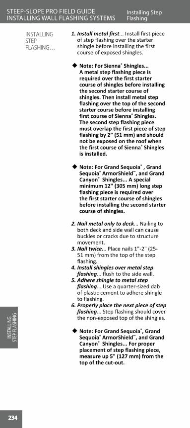
234
INSTALLING SHINGLE VALLEYS
234
1. Install metal first... Install first piece of step flashing over the starter shingle before installing the first course of exposed shingles.
w Note: For Sienna® Shingles... A metal step flashing piece is required over the first starter course of shingles before installing the second starter course of shingles. Then install metal step flashing over the top of the second starter course before installing first course of Sienna® Shingles. The second step flashing piece must overlap the first piece of step flashing by 2” (51 mm) and should not be exposed on the roof when the first course of Sienna® Shingles is installed.
w Note: For Grand Sequoia® , Grand Sequoia® ArmorShield™, and Grand Canyon® Shingles... A special minimum 12" (305 mm) long step flashing piece is required over the first starter course of shingles before installing the second starter course of shingles.
2. Nail metal only to deck... Nailing to both deck and side wall can cause buckles or cracks due to structure movement.
3. Nail twice... Place nails 1"-2" (25-51 mm) from the top of the step flashing.
4. Install shingles over metal step flashing... flush to the side wall.
5. Adhere shingle to metal step flashing... Use a quarter-sized dab of plastic cement to adhere shingle to flashing.
6. Properly place the next piece of step flashing... Step flashing should cover the non-exposed top of the shingles.
w Note: For Grand Sequoia®, Grand Sequoia® ArmorShield™, and Grand Canyon® Shingles... For proper placement of step flashing piece, measure up 5" (127 mm) from the top of the cut-out.
ROO
FIN
G
BASI
CS
INSTALLINGSTEPFLASHING…
Installing Step Flashing
STEEP-SLOPE PRO FIELD GUIDE INSTALLING WALL FLASHING SYSTEMS
INST
ALLIN
G ST
EP FL
ASHI
NG
234234234234234234234234234

235
7. Continue up the roof... • One step flashing piece per
shingle... to ensure a sealed system.
• Alternate for large-exposure shingle (see dimension chart on page 233)... Use two overlapped 7" (178 mm) step flashing pieces per shingle course.
8. Fully cover step flashing... Shingles should cover step flashing completely for best appearance and waterproofing.
9. Cover step flashing with counter flashing... Cover the top of the step flashing on the wall a minimum of 2" (51 mm).
10. Follow the siding manufactuerer's recommendations... for clearance above the the shingles. This clearance is generally a minimum of 2" (51 mm) above the roof deck.
New metal step flashing is
required on all Weather Stopper® Golden Pledge® and Silver Pledge® installations (unless existing metal step flashing is in like-new condition).Step flashing is required at all dormers, chimneys, and side walls.
w Note: Do NOT use "L" flashing at the upslope sides of dormers, side walls, and chimneys. This method is dependent on roofing cement and can leak over time.
WEATHER STOPPER® GOLDEN PLEDGE® AND SILVER PLEDGE® NOTE…
ROO
FING
BA
SICSInstalling Step Flashing
STEEP-SLOPE PRO FIELD GUIDE INSTALLING WALL FLASHING SYSTEMS
Installing Step Flashing
INSTALLING STEP FLASHING

236
INSTALLING W
ALL FLASHING
236
ROO
FIN
G
BASI
CS
STANDARD 5" (127 mm) EXPOSURE ENGLISH-SIZED SHINGLES…
STANDARD 5 5/8" (143 mm) EXPOSURE METRIC-SIZED SHINGLES…
Installing Step Flashing
STEEP-SLOPE PRO FIELD GUIDE INSTALLING WALL FLASHING SYSTEMS
INST
ALLIN
G ST
EP FL
ASHI
NG
236236236236236236236236236
Step flashing for metric-sized shingle 131/4" x 393/8" (337 mm x 1 m) with 53/8" (143 mm) exposure
Step flashing for English-sized shingle 12" x 36" (305 mm x 914 mm) with 5" (127 mm) exposure

237
ROO
FING
BA
SICS
LARGE 7 1/2" (190 mm) EXPOSURE…
Installing Step Flashing
STEEP-SLOPE PRO FIELD GUIDE INSTALLING WALL FLASHING SYSTEMS
Preferred step flashing for large 71/2" (190 mm) exposure shingles
Alternate 2-piece step flashing
Installing Step Flashing
INSTALLING STEP FLASHING

238
INSTALLING W
ALL FLASHING
238
ROO
FIN
G
BASI
CS
INSTALLING STARTER COURSE STEP FLASHING…
w Note: Special size for starter course step flashing.
GRAND SEQUOIA® AND GRAND CANYON® SHINGLES...
Installing StepFlashing
STEEP-SLOPE PRO FIELD GUIDE INSTALLING WALL FLASHING SYSTEMS
INST
ALLIN
G ST
EP FL
ASHI
NG
238238238238238238238238238

239
ROO
FING
BA
SICSInstalling StepFlashing
STEEP-SLOPE PRO FIELD GUIDE INSTALLING WALL FLASHING SYSTEMS
NORMAL COURSE STEP FLASHING
STEP FLASHING GRAND SEQUOIA® AND GRAND CANYON® SHINGLES: FIRST AND SUBSEQUENT COURSES…
Installing StepFlashing
INSTALLING STEP FLASHING

240
INSTALLING W
ALL FLASHING
240
w Install metal flashing where a roof plane intersects horizontal walls…
• Dormer fronts. • Wall fronts. • Shed roof wall seams.
w Ventilate over heated or air-condi-tioned areas… Shed roofs and dor-mer fronts need to be ventilated.w Install Cobra® Exhaust Vent...
following the method described in “Shed-Style Roof Ventilation” on page 104.
1. Install Deck-Armor™ or other GAF Roof Deck Protection … up to the wall seam flush to the wall.
2. Install GAF Leak Barrier… full 36" (914 mm) width over Deck-Armor™ or other GAF Roof Deck Protection to seal this area.
3. Extend up wall 5" (127 mm) min.4. Seal to wall and Deck Armor™ or
other GAF Roof Deck Protection… • Do not seal to deck… If the build-
ing moves, Leak Barrier does not crack or tear.
5. Install shingles flush to wall… Trim even with the wall seam.
6. Install metal “apron” flashing… for full protection.
• Over the shingles. • Extend up wall 5" (127 mm) min.
(behind siding). • Extend over shingles 4" (102 mm)
min. Required procedure for Weather
Stopper® Golden Pledge® and Silver Pledge® installations is to follow all of these steps.
ROO
FIN
G
BASI
CS
HORIZONTAL WALLS…
VENTILATING HORIZONTAL WALL FRONTS…
FLASHING WHEN NOT VENTILATING…
WEATHER STOPPER® GOLDEN PLEDGE® AND SILVER PLEDGE® NOTE…
Flashing Horizontal Sidewalls
STEEP-SLOPE PRO FIELD GUIDE INSTALLING WALL FLASHING SYSTEMS
INST
ALLIN
G W
ALL F
LASH
ING
240240240240240240240240240
INSTALLING W
ALL FLASHINGINSTALLING
WALL FLASHING

241
7. Nail metal to wall… but not the roof deck in case of settling or movement.
8. If desired, install cut shingles over apron flashing… by embedding them in plastic roof cement.
Note: Excess cement can cause shingles to blister.
ROO
FING
BA
SICS
FLASHING HORIZONTAL WALL SEAMS…
Flashing Horizontal Sidewalls
STEEP-SLOPE PRO FIELD GUIDE INSTALLING WALL FLASHING SYSTEMS
Flashing Horizontal Sidewalls
INSTALLING W
ALL FLASHING
242
INSTALLING W
ALL FLASHING
242
1. True or False: GAF prefers that you install Deck-Armor™ or other GAF Roof Deck Protection under Leak Barriers at vertical walls and side walls.
A. True B. False
2. How far should step flashing extend up the side wall and over the deck?
A. 5" (127 mm) min. over shingles and side walls. B. 3" (76 mm) at side walls, 3" (76 mm) min. over decks. C. 9" (229 mm) up side walls, 5" (127 mm) min. over
decks. D. Both A and B above.
3. Why does GAF recommend fastening step flashing to the decking and not to the side walls?
A. To ensure the side walls do not crack. B. To keep flashing from moving in the wind. C. So that the flashing will not buckle or crack if the side
wall moves or settles. D. Both A and B above.
4. Why is the use of “L” flashing not recommended for shingle installations?
A. This method is dependent on roofing cement, and can leak over time.
B. “L” flashing will channel the water. C. “L” flashing rusts quicker. D. “L” flashing is more likely to blow off of a roof.
5. True or False: Step flashing is required at all dormers, side walls, and chimneys on Weather Stopper® Golden Pledge® installations.
A. True B. False
REVIEW #20STEEP-SLOPE PRO FIELD GUIDE IN
STAL
LING
WAL
L FLA
SHIN
G
242242242242242242242242242
INSTALLING W
ALL FLASHINGINSTALLING
WALL FLASHING

Crickets
243
Chimney leak areas… • Ponding water… The area behind
the chimney is prone to leaks due to nonmoving water.
• Flashing leaks… The seams at chimney sides are leak concerns.
• Ice dams… When snow and ice get stuck behind chimneys, leaks occur.
Chimney crickets make good sense… • Divert water… Crickets keep water
flowing around chimneys. • Reduce ponding… Crickets eliminate
ponding water behind chimneys. • Reduce ice back-up… Crickets
keep ice from building up behind chimneys.
• Deflect water away from seams… Properly installed crickets keep water flowing away from the chimney seams.
When installing crickets on a Weather Stopper® Golden Pledge® and Silver Pledge® Limited Warranty roof, crickets must be installed.
1. On all roofs steeper than 6:12… to handle water volume.
2. On all chimneys wider than 24" (610 mm)… to reduce ponding water.
3. On all chimneys in the north… due to ice dams, snow loads, and the freeze-thaw cycle.
WEATHER STOPPER® GOLDEN PLEDGE® AND SILVER PLEDGE® NOTE…
CHIMNEY CRICKETS…
CHIMNEYS…“CHIMNEYS ARE THE MOST COMMON LEAK SOURCE IN RESIDENTIAL ROOFING.”
STEEP-SLOPE PRO FIELD GUIDE INSTALLING CHIMNEY FLASHING SYSTEMSREVIEW #20
INSTALLING CHIM
NEY FLASHING
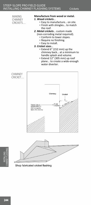
244
Flashing Chimneys
INSTALLING CHIM
NEY FLASHING
244
Manufacture from wood or metal.1. Wood crickets… • Easy to manufacture… on site. • Finish with shingles… to match
the roof.2. Metal crickets… custom made
(non-corroding metal required). • Conform to lower slopes. • Require no finishing. • Easy to install.3. Cricket sizes… • Extend 6" (152 mm) up the
chimney back… at a minimum to handle splash and volume.
• Extend 12" (305 mm) up roof plane… to create a wide-enough water diverter.
ROO
FIN
G
BASI
CS
CHIMNEY CRICKET…
MAKING CHIMNEY CRICKETS…
CricketsSTEEP-SLOPE PRO FIELD GUIDE INSTALLING CHIMNEY FLASHING SYSTEMS
INST
ALLIN
G CH
IMNE
Y FLA
SHIN
G
244244244244244244244244244244
-
INSTALLING CHIM
NEY FLASHINGINSTALLING
CHIMNEY FLASHING

245
1. Install Deck-Armor™ or other GAF Roof Deck Protection… all around the chimney sides and over wood crickets.
• Do NOT run Deck-Armor™ or other GAF Roof Deck Protection up chimney sides… so that Leak Barrier can seal to the chimney sides.
2. Install WeatherWatch® or StormGuard® Leak Barrier… over Shingle-Mate® or Deck-Armor™ Roof Deck Protection.
• Seal to the Deck-Armor™ or other GAF Roof Deck Protection... to waterproof this area.
• Seal to chimney sides… at least 5" (127 mm) up walls to completely seal off water infiltration.
• Protects from movement or settling… Chimneys and roof decks move independently. Leak Barrier adhered to both could split or crack with structural movement.
UNDERLAYMENT DIAGRAM…
UNDERLAYMENT AT CHIMNEYS…
ROO
FING
BA
SICSFlashing Chimneys
STEEP-SLOPE PRO FIELD GUIDE INSTALLING CHIMNEY FLASHING SYSTEMS
INSTALLING CHIM
NEY FLASHING

246
INSTALLING CHIM
NEY FLASHING
246
1. Reuse existing apron flashing… only when the existing flashing is in excellent condition.
• Will it last the shingle's life?… Consider whether the old flashing will last as long as the shingles being installed.
2. Install new apron flashing… when working on new construction or when existing flashing is deteriorated.
3. Embed in chimney mortar… to ensure long-lasting apron flashing.
4. Apron flashing dimensions… • 6" (152 mm) minimum up
from deck… to create room for step flashing.
• 4" (102 mm) minimum over shingle at front… to seal off this roof seam.
• 4" (102 mm) minimum over shingles at sides… to start off the step flashing properly.
• 10" (254 mm) minimum. wrapped around corner… to cover the step flashing.
5. Shingle up to chimney… trimming the shingles flush to the chimney front.
6. Place apron over shingles… embedded in plastic roof cement to ensure they seal.
7. Conform corners to chimney… bend and place over chimney sides.
8. Start step flashing… up the chimney sides.
9. Install step flashing metal first… at corners before installing shingles to chimney sides.
10. Install counter flashing... see pages 249-255.
New metal apron flashing is required on all Weather Stopper® Golden Pledge® and Silver Pledge® installations (unless existing metal apron flashing is in like-new condition).
ROO
FIN
G
BASI
CS
APRON FLASHING…
Flashing Chimneys
STEEP-SLOPE PRO FIELD GUIDE INSTALLING CHIMNEY FLASHING SYSTEMS
INST
ALLIN
G CH
IMNE
Y FLA
SHIN
G
WEATHER STOPPER® GOLDEN PLEDGE® AND SILVER PLEDGE® NOTE…
246246246246246246246246246246
INSTALLING CHIM
NEY FLASHINGINSTALLING
CHIMNEY FLASHING

247
INSTALLING APRON FLASHING…
ROO
FING
BA
SICSFlashing Chimneys
STEEP-SLOPE PRO FIELD GUIDE INSTALLING CHIMNEY FLASHING SYSTEMS
Flashing Chimneys
INSTALLING CHIM
NEY FLASHING

248
INSTALLING CHIM
NEY FLASHING
248
1. Always install new metal step flashing at chimneys…
• Ensures weathertightness… Installing new metal is the only way to ensure weathertightness.
• Easy to do… When reroofing, simply remove old metal and install new metal.
2. Install metal step flashing… at chimney bottom corners before installing shingles at that course.
• Wrap around corner… Cut flashing to wrap around chimney front.
3. Step flashing sizes… for complete coverage:
• Fully cover shingle’s top area. • 5" (127 mm) minimum over
shingle face. • 5" (127 mm) minimum up the
chimney side. 4. Install shingle course… to side of
chimney. 5. Seal flashing to shingle… with a
quarter-sized dab of plastic roof cement to ensure against blow-offs, wind-driven rain, and ice backup. Note: Excess cement can cause shingles to blister.
6. Place next step flashing piece… In-stall to bottom of shingle exposure without exposing any metal.
7. Continue up the chimney… installing one step flashing piece for every shingle.
8. Seal each shingle to step flash-ing... for watertightness.
9. Wrap last piece around corner… to finish off the chimney sides.
10. Install counter flashing... see pages 249-255.
Required procedure for Weather Stopper® Golden Pledge® and Silver Pledge® Installations is to follow all of these steps.
ROO
FIN
G
BASI
CS
STEP FLASHING CHIMNEYS…
Flashing Chimneys
STEEP-SLOPE PRO FIELD GUIDE INSTALLING CHIMNEY FLASHING SYSTEMS
INST
ALLIN
G CH
IMNE
Y FLA
SHIN
G
WEATHER STOPPER® GOLDEN PLEDGE® AND SILVER PLEDGE® NOTE…
248248248248248248248248248248248
INSTALLING CHIM
NEY FLASHINGINSTALLING
CHIMNEY FLASHING

249
INSTALLING STEP FLASHING AT CHIMNEYS…
COUNTER FLASHING…
Flashing Chimneys
STEEP-SLOPE PRO FIELD GUIDE INSTALLING CHIMNEY FLASHING SYSTEMS
Flashing Chimneys
INSTALLING CHIM
NEY FLASHING

250
INSTALLING CHIM
NEY FLASHING
250
1. Finish like a separate roof… Install shingles and step flashing up the cricket sides.
2. Install “valleys”… Treat roof and cricket intersection like any valley.
3. Conform valley style to roof… Install these valleys with the method appro-priate to the shingle being installed.
4. Cap the ridge… Install capping from the chimney out to the roof.
5. Tie final cap under shingles… The last cap installed should be tied up under the roofing shingles to main-tain watertightness.
6. Install counter flashing... see pages 249-255.
ROO
FIN
G
BASI
CS
FINISHING WOOD CRICKETS…
Flashing Chimneys
STEEP-SLOPE PRO FIELD GUIDE INSTALLING CHIMNEY FLASHING SYSTEMS
INST
ALLIN
G CH
IMNE
Y FLA
SHIN
G
250250250250250250250250250250250
INSTALLING CHIM
NEY FLASHINGINSTALLING
CHIMNEY FLASHING

251
1. Install shingles and flashing… just past the chimney top corners.
2. Install the metal cricket.3. Metal cricket dimensions… • 4" (102 mm) down from corners…
extending over the shingles down the chimney sides.
• 6" (152 mm) across roof deck… covering existing shingles 6" (152 mm) min. on roof.
• 18" (457 mm) minimum to flange top… from the chimney corner to give wide coverage.
• 12" (305 mm) minimum cricket ridge line… to create water diverter.
4. Tie-in to chimney mortar at top… to make a permanent bond (see page 253 “Installing Counter Flashing”).
5. Seal to shingles at front… with plastic asphalt cement for weathertightness.
6. Seal to underlayments at back… before installing shingles.
7. Seal to chimney back… to seal off this critical seam.
8. Install shingles over flange… sealing to metal with plastic asphalt cement.
9. Install counter flashing... see pages 249-255.
FINISHED METAL CRICKET…
INSTALLING METAL CRICKETS…
ROO
FING
BA
SICSFlashing Chimneys
STEEP-SLOPE PRO FIELD GUIDE INSTALLING CHIMNEY FLASHING SYSTEMS
Flashing Chimneys
INSTALLING CHIM
NEY FLASHING

252
INSTALLING CHIM
NEY FLASHING
252
1. Reuse existing counter flashing… when the metal is in a condition to last the life of the shingles being installed.
2. Install new counter flashing… on new construction or when the old flashing is deteriorated.w Replace counter flashing if existing
metal is… • Rusted galvanized metal. • Cracked, hole-filled metal. • Aged or deteriorated metal.
w Permanently attach to chimney… by either setting in mortar or mechanically attaching.
Into mortar joint…1. Cut into old mortar joint 1 1/2" (38
mm)... minimum to set counter flashing.
2. Set metal into mortar joint… • Clean out mortar joint. • Set 1/2" (13 mm) mortar bed. • Install metal counter flashing. • Set second bed of mortar over
metal in seam.Mechanically attaching…1. Cut into old mortar joint 1 1/2" (38
mm)... minimum to set counter flashing.
2. Set counter flashing into seam… using counter flashing with friction fitting.
3. Drive soft metal wedge into friction fitting… to fasten counter flashing to chimney.
4. Seal the joint… with plastic roof cement or polyurethane sealant.
• Sealant should fill the joint fully. • Sealant should seal to masonry.
On Weather Stopper® Golden Pledge® and Silver Pledge® installations, new metal counter flashing must be installed unless existing flashing is in like-new condition.
ROO
FIN
G
BASI
CS
WHEN TO REUSE EXISTING COUNTER FLASHING…
INSTALLING COUNTER FLASHING…
Flashing Chimneys
STEEP-SLOPE PRO FIELD GUIDE INSTALLING CHIMNEY FLASHING SYSTEMS
INST
ALLIN
G CH
IMNE
Y FLA
SHIN
G
WEATHER STOPPER® GOLDEN PLEDGE® AND SILVER PLEDGE® NOTE…
252252252252252252252252252252252
INSTALLING CHIM
NEY FLASHINGINSTALLING
CHIMNEY FLASHING

253
ATTACHING NEW METAL COUNTER FLASHING WITH MORTAR
MECHANICALLY ATTACHING NEW METAL COUNTER FLASHING…
ROO
FING
BA
SICSFlashing Chimneys
STEEP-SLOPE PRO FIELD GUIDE INSTALLING CHIMNEY FLASHING SYSTEMS
Flashing Chimneys
INSTALLING CHIM
NEY FLASHING

254
INSTALLING CHIM
NEY FLASHING
254
1. Fold metal over step flashing and cricket… starting at the chimney base working up the roof.
2. 2" (51 mm) minimum overlap… Counter flashing should overlap step flashing by 2" (51 mm) min.
3. Tight to chimney… Counter flashing should be installed tight to the chimney sides.
w When a cricket is not necessary, finish the chimney back with metal backer flashing.
Reminder: crickets are recommended… • On chimneys wider than 24"
(610 mm) . • On all roofs steeper than 6:12. • On all chimneys in the North.
On Weather Stopper® Golden Pledge® and Silver Pledge® installations, chimney crickets are required in all of the above listed situations.
1. Customize to chimney… Make backer flashing specifically for each chimney.
2. Backer flashing size… • 6" (152 mm) wider than
chimney. • 18" (457 mm) up roof plane. • 6" (152 mm) up chimney back.3. Permanently fasten to chimney…
with either new mortar or mechanical fastening as with counter flashing.
4. Install over shingles… Backer flashing gets installed over the shingle course that is even with chimney top corner.
5. Set in plastic cement… to seal to shingles and underlayments.
Note: Excess cement can cause shingles to blister.
ROO
FIN
G
BASI
CS
INSTALLING COUNTER FLASHING…
COUNTER FLASHING DIAGRAM…
BACKER FLASHING…
Flashing Chimneys
STEEP-SLOPE PRO FIELD GUIDE INSTALLING CHIMNEY FLASHING SYSTEMS
INST
ALLIN
G CH
IMNE
Y FLA
SHIN
G
WEATHER STOPPER® GOLDEN PLEDGE® AND SILVER PLEDGE® NOTE...
254254254254254254254254254254254254
INSTALLING CHIM
NEY FLASHINGINSTALLING
CHIMNEY FLASHING

255
6. Fasten to deck… at upper end of roof flange.
7. Shingle over flange… Carry shingles over the metal flange to cover flange.
8. Seal shingles to flange… to ensure watertightness.
9. Install counter flashing… to finish off the flashing system, bend and seal over flashing at chimney sides.
ROO
FING
BA
SICSFlashing Chimneys
STEEP-SLOPE PRO FIELD GUIDE INSTALLING CHIMNEY FLASHING SYSTEMS
Flashing Chimneys
INSTALLING CHIM
NEY FLASHING

256
INSTALLING CHIM
NEY FLASHING
256
Safety caps for chimneys… help protect against sparks, and reduce downdrafts and clogging; also help to protect against animal infestation and deflect debris and rain to keep them from entering chimneys.
w Single-piece construction for longer life.w Epoxy powder finish provides long-
lasting protection.w Quick easy installation. No rivets or
seams to rust or corrode.w Available in galvanized or stainless
steel material.
1. Insert screws into each hole in the base… Secure with a few turns to ease installation.
2. Place chimney cap on flue… Align the base with the flue liner for secure fit.
3. Tighten screws… to secure in place.
If the liner is extended less than 3/4" (19 mm) out of the mortar and screws do not engage securely, a leg kit is required…
1. Align legs in chimney cap… Follow illustration on packaging for alignment.
2. Insert bolt… through hole in leg and base.
3. Thread self-locking nut… Two to three turns onto the bolt, so it is not tight.
4. Insert two legs into liner… no more than 1" (25 mm).
5. Force other legs into liner… all four legs are now in liner.
6. Push cover into liner… as far as possible to ensure a tight fit.
7. Tighten bolts… on all four legs so the cover is held firmly in place.
IF A LEG KIT IS NEEDED…
MASTER FLOW® CHIMNEY CAPS…
Safety Caps for Chimneys
STEEP-SLOPE PRO FIELD GUIDE INSTALLING CHIMNEY FLASHING SYSTEMS
INST
ALLIN
G CH
IMNE
Y FLA
SHIN
G
256256256256256256256256256256256256256
INSTALLING CHIM
NEY FLASHINGINSTALLING
CHIMNEY FLASHING

257
1. Insert screw into U-Bracket… Use pre-threaded hole located on the side of the bracket.
2. Insert “T” shaped tab… into slotted brace of chimney cap.
3. Slide U-Brackets in… down slot toward center of chimney cap.
4. Turn U-Brackets… 1/4 turn with screw head facing outside of cap.
5. Position cap above flue tile.6. Slide U-Brackets along braces… Align
above the sides of the flue and lower into position.
• Tighten screws… Apply downward pressure on cap while securing to ensure a tight fit.
INSTALLING AN ADJUSTABLE CHIMNEY CAP…
ROO
FING
BA
SICSSafety Caps for Chimneys
STEEP-SLOPE PRO FIELD GUIDE INSTALLING CHIMNEY FLASHING SYSTEMS
INSTALLING CHIM
NEY FLASHINGSafety Caps for Chimneys

258
INSTALLING CHIM
NEY FLASHING
258
1. Where are chimney crickets necessary? A. On all chimneys in the North. B. On all chimneys wider than 24" (610 mm). C. On all roofs steeper than 6:12. D. All of the above.
2. How far up the back of a chimney should a chimney cricket extend?
A. 3" (76 mm). B. 4" (102 mm). C. 5" (127 mm). D. 6" (152 mm).
3. How far up a chimney's sides should you install Leak Barriers?
A. 3" (76 mm). B. 4" (102 mm). C. 5" (127 mm). D. 6" (152 mm).
4. When should you install new metal counter flashing on a chimney?
A. When the metal is aged or deteriorated. B. When there are cracks or holes in the metal. C. When the metal is rusted. D. All of the above.
5. True or False: Master Flow® Chimney Caps help protect against sparks, downdrafts, and animal infestation.
A. True B. False
ROO
FIN
G
BASI
CSREVIEW #21STEEP-SLOPE PRO FIELD GUIDE
INST
ALLIN
G CH
IMNE
Y FLA
SHIN
G
258258258258258258258258258258258258258
INSTALLING CHIM
NEY FLASHING

259
w GAF recommends the use of skylights with a factory-manufactured step flashing system…
1. Install Deck-Armor™ or other GAF Roof Deck Protection… flush to the skylight sides.
2. Install GAF Leak Barrier… • Around entire skylight. • Up the skylight sides. • Over the underlayment.3. Install shingles flush to skylight…
trimming shingles flush to the skylight front.
4. Install skylight apron flashing… seal to shingles with plastic cement.
5. Install step flashing… one shingle per step flashing piece.
• Nail to deck only… to reduce the potential of buckles with deck and skylight movement.
• Extend up skylight side as high as possible… without interfering with skylight opening and closing.
6. Seal shingles to step flashing… with a quarter-sized dab of plastic cement to eliminate blow-offs. w Caution: Excess amount of cement
can cause blistering of shingles.7. Install backer flashing… with metal
extending upslope 18" (457 mm) minimum
8. Install skylight manufacturer’s counter flashing… should extend over step flashing 2" (51 mm) minimum.
9. Refer to manufacturer’s instructions… to properly install skylights.
Required procedure for the Weather Stopper® Golden Pledge® and Silver Pledge® Limited Warranty is to follow all of these steps.
SEAL OFF A NOTORIOUS LEAK SOURCE…
WEATHER STOPPER® GOLDEN PLEDGE® AND SILVER PLEDGE® NOTE…
ROO
FING
BA
SICSSkylight Flashing
STEEP-SLOPE PRO FIELD GUIDE FLASHING ROOF PROJECTIONSREVIEW #21
FLASHING ROOF PROJECTIONS

260
FLASHING ROOF PROJECTIONS
260
ROO
FIN
G
BASI
CSSkylight Flashing
STEEP-SLOPE PRO FIELD GUIDE FLASHING ROOF PROJECTIONS
FLAS
HING
RO
OF PR
OJEC
TIONS
FLASHING SKYLIGHT DIAGRAM…
Skylight
Apron flashingwith lower edgehemmed under
Backer flashingextends upslopeunder shingles
Install GAF LeakBarrier up curbsides
Counterlashing lapsover step flashing 2"(51 mm) min.
Step flashing
260260260260260260260260260260260260260260
FLASHING ROOF PROJECTIONS
FLASHING ROOF PROJECTIONS

261
1. Apply Deck-Armor™ or other GAF Roof Deck Protection… flush to the vent pipe’s sides.
2. Install a 20" (508 mm) wide square of GAF Leak Barrier… over the pipe, sealing to pipe sides and to the underlayment.
3. Shingle up to the vent pipe.4. Fit shingle over pipe… Trim a hole in
the shingle so it fits tightly around the vent pipe.
5. Seal in the shingle… with a bead of plastic cement around the pipe.
6. Set pipe flange in place… over pipe into a bed of plastic cement. (Note: Excess cement can cause shingles to blister.)
7. Seal pipe flange to pipe… at the top exposed area with plastic cement.
8. Install shingles over flange… up slope and continue installing shingles.
9. Seal lower part of flange… Flange front should sit flush to deck without face nailing.
For more plumbing vent installation details, see pages 56-57.
Required procedure on all Weather Stopper® Golden Pledge® and Silver Pledge® installations is to follow all of these steps.
SEALING OFF PLUMBING VENTS…
WEATHER STOPPER® GOLDEN PLEDGE®
AND SILVER PLEDGE® NOTE…
SEALING A COMMON LEAK SOURCE…
ROO
FING
BA
SICSFlashing Plumbing Vent
STEEP-SLOPE PRO FIELD GUIDE FLASHING ROOF PROJECTIONS
FLASHING ROOF PROJECTIONS
Skylight Flashing

262
FLASHING ROOF PROJECTIONS
262
1. Install Deck-Armor™ or other GAF Roof Deck Protection… up to the transition.
2. Install GAF Leak Barrier… a full 36" (914 mm) width centered over transition area, installed over the down-slope underlayment.
3. Shingle to the transition center… install shingles up to the transition.
4. Install rolled metal flashing… 20" (508 mm) wide, corrosion resistant, over the top of the shingles.
5. Set metal in a bead of plastic cement… to seal to down-slope shingles (Caution: Too much cement may cause shingles to blister).
6. Install Deck-Armor or other GAF Roof Deck Protection… on the upper slope area, starting with a 2" (51 mm) lap over the Leak Barrier.
7. Install shingles over metal up-slope… to ensure water flow over the metal and out of the roof system.
Installing GAF Leak Barrier at shingle-to-shingle transitions is recommended (not required) on Weather Stopper® Golden Pledge® and Silver Pledge® installations.
HIGH-SLOPE TO LOW-SLOPE TRANSITIONS…
Flashing High-Low Transitions
STEEP-SLOPE PRO FIELD GUIDE FLASHING ROOF PROJECTIONS
FLAS
HING
RO
OF PR
OJEC
TIONS
WEATHER STOPPER® GOLDEN PLEDGE® AND SILVER PLEDGE® NOTE…
FLASHING HIGH-LOW TRANSITIONS…
262262262262262262262262262262262262262262
FLASHING ROOF PROJECTIONS

263
1. Install GAF Leak Barrier… a full 36" (914 mm) centered over the transition area.
• Install over the Deck-Armor™ or other GAF Roof Deck Protection… at the down-slope side and under the Roof Deck Protection on the up-slope side to ensure water flows out of the roof system.
2. Shingle up to the transition… install shingles up to the transition and over the center line.
3. Install rolled metal flashing… over the down-slope shingles.
4. Seal metal to shingles… on the down-slope side to seal this area.
5. Apply shingles over metal up-slope… to ensure water flows over the shingles and out of the system.
6. Seal shingle to the metal… with plastic roof cement. (Caution: Too much cement can cause shingles to blister.)
Installing GAF Leak Barrier at shingle-to-shingle transitions is recommended (not required) on Weather Stopper® Golden Pledge® and Silver Pledge® installations.
LOW-SLOPE TO STEEP-SLOPE TRANSITIONS…
ROO
FING
BA
SICSFlashing Shingle-to- Shingle Transitions
STEEP-SLOPE PRO FIELD GUIDE FLASHING ROOF PROJECTIONS
WEATHER STOPPER® GOLDEN PLEDGE® AND SILVER PLEDGE® NOTE…
FLASHING ROOF PROJECTIONS
Flashing High-Low Transitions

264
FLASHING ROOF PROJECTIONS
264
1. True or False: GAF recommends the use of skylights with a factory-manufactured step flashing system.
A. True B. False
2. Why install GAF Leak Barriers around plumbing vents? A. So that the Leak Barrier will seal the area around
the vent pipe. B. To keep the underlayment from interfering with the
plumbing vent. C. To allow for more air flow through the pipe. D. Both B and C.
3. What size should the Leak Barrier be around a plumb-ing vent pipe?
A. 12" (305 mm). B. 16" (406 mm). C. 18" (457 mm). D. 20" (508 mm).
4. What size width should the metal flashing be at the slope transition area?
A. 24" (610 mm) B. 16" (406 mm) C. 8" (203 mm) D. 20" (508 mm)
5. True or False: The metal flashing at a shingle-to-shingle transition should be set into a bed of plastic cement.
A. True B. False
ROO
FIN
G
BASI
CSREVIEW #22STEEP-SLOPE PRO FIELD GUIDE
FLAS
HING
RO
OF PR
OJEC
TIONS
264264264264264264264264264264264264264264
FLASHING ROOF PROJECTIONS

265
w A safer, faster roofing solution • No open torches. • No flames. • No unpleasant fumes.w For low-slope projects… • Porches • Garages • Carports • Other low-slope
projects
1. Liberty™ SBS Self-Adhering Cap Sheet... SBS self-adhering cap sheet.
2. Liberty™ Self-Adhering Base/Ply Sheet… SBS self-adhering base/ply sheet.
3. Liberty™ SBS Mechanically Attached Base Sheet… Nailable SBS base sheet with bonded film.
4. Matrix™ 307 Asphalt Primer… ASTM D41 Primer.
5. Matrix™ 201 Premium SBS Flashing Cement… Modified adhesive compatible with the membrane.
1. Premium 3-Ply System… Consists of Liberty™ SBS Mechanically Attached Base Sheet, Liberty™ Self-Adhering Base/Ply Sheet, and Liberty™ SBS Self-Adhering Cap Sheet.
• Eligible for 15-year Weather Stopper® Golden Pledge® and Silver Pledge® Limited Warranty Addendum.*
• Eligible for a 15-year limited warranty.*
2. Premium 2-Ply System… Consists of one Liberty™ Self-Adhering Base/Ply Sheet and a top ply of Liberty™ SBS Self-Adhering Cap Sheet.w Note: Do NOT apply directly to
plywood substrates on jobs larger than 2,000 sq. ft (186 m2).
• Eligible for 12-year Weather Stopper® Golden Pledge® and Silver Pledge® Limited Warranty Addendum, or a 15-year limited warranty.*
2a. Alternate 2-Ply System… Consists of Liberty™ MA Mechanically Attached Base Sheet and a top ply of Liberty™ SBS Self-Adhering Cap Sheet.
• Eligible for 12-year Weather Stopper® Golden Pledge® and Silver Pledge® Limited Warranty Addendum, or a 10-year limited warranty.*
3. Value 1-Ply System… Consists of one layer of Liberty™ SBS Self-Adhering Cap Sheet.w Note: Do NOT apply directly to
plywood substrates on jobs larger than 2,000 sq.ft. (186 m2).
• Eligible for a 10-year limited warranty.*
MATERIALS NEEDED…
THE SYSTEMS…
LIBERTY™ SELF- ADHERING MEMBRANE…
ROO
FING
BA
SICSLiberty™ Products and Systems
STEEP-SLOPE PRO FIELD GUIDE LIBERTY™ SELF-ADHERED MEMBRANEREVIEW #22
LIBERTY™ SELF-
ADHERED MEMBRANE

266
LIBERTY™
SELF-ADHERED MEMBRANE
266
Weather Stopper® Golden Pledge® and Silver Pledge® Addendums are only available where total low-slope area coverage is 20 squares (186 m2) or less and must be separately applied for. Other limitations may apply. See Weather Stopper® Golden Pledge® and Silver Pledge® Warranty Addendums for coverage and restrictions.
1. Positive drainage required… The Liberty™ System must be installed on roofs with slopes between 1/4:12 and 3:12. Areas of ponding water are unacceptable.
2. Install in warm, dry conditions… Decks must be dry and temperature must be between 45oF and 95oF (7-35oC).
3. The roof deck must be smooth… Any holes must be covered with minimum 32-gauge sheet metal nailed to the deck.
4. When reroofing… Remove existing materials down to an acceptable deck, remove any obsolete protrusions, reseat any protruding nails, and repair any cracks, splits, voids, or openings greater than 1/4" (6 mm).
5. Back nail cap sheets on slopes of 1/2:12 or higher... Nail in selvage area 9" (229 mm) on center with minimum 1" (25 mm) cap installed 1" (25 mm) below top edge of each ply.
ROO
FIN
G
BASI
CS
GENERAL GUIDELINES…
General Guide lines & Surface Preparation
STEEP-SLOPE PRO FIELD GUIDE LIBERTY™ SELF-ADHERED MEMBRANE
LIBER
TY™ S
ELF-
ADHE
RED
MEMB
RANE
266266266266266266266266266266266266266266266
WEATHER STOPPER® GOLDEN PLEDGE®
AND SILVER PLEDGE® ADDENDUM NOTE…

267
1. Apply Matrix™ 307 Premium Asphalt Primer, or a comparable ASTM D41-type primer... to the minimum 15/32" (12 mm) plywood deck when installing Liberty™ Self-Adhering Base/Ply Sheet or Liberty™ SBS Self-Adhering Cap Sheet direct to plywood. Prime with 1/2 gallon per 100 sq. ft. (2.04 L/10 m2) and allow to dry. Prior to priming, tape all joints with duct tape.
2. Starting at the low point of the roof… Strike a chalk line as a guide to keep base sheet parallel to eave. Allow enough overhang to extend down over the fascia behind the full height of the metal edge or gutter.
3. Trim base sheets to offset sidelaps… For 2-ply systems, install first course with 1/2 width (19 11/16" [500 mm]) sheets of Liberty™ Self-Adhering Base/Ply Sheet. Install following courses with full-width sheets, making certain base sheet side laps and end laps are offset from the cap sheet.
4. Align a manageable length… (a length that allows a wrinkle-free installation) of this first course of Liberty™ Self-Adhering Base/Ply Sheet with the edge of the roof.
5. Fold back the upper edge (not the eaves edge) of the Liberty™ Self-Ad-hering Base/Ply Sheet to expose the underside of the sheet… and remove only the upper portion (approximately 7 1/2" [191 mm] ) of the split-back release film.
6. Gradually set the Liberty™ Self- Adhering Base/Ply Sheet back in place… making sure that the upper edge remains aligned with the chalk line. Apply even pressure along the length (from center to outer edges) to avoid air bubbles and wrinkles.
7. Fold up onto the roof the lower portion… of the Liberty™ Self-Adhering Base/Ply Sheet, remove remaining release film, and lay the Liberty™ Self-Adhering Base/Ply Sheet back onto the roof. Apply even pressure from center to outer edge to avoid wrinkles or air bubbles. Press firmly onto the fascia board if a gutter is to be installed. Fold sheet down the fascia and press firmly onto fascia board, and nail on 6" (152 mm) centers.
LIBERTY™
SELF-ADHERING BASE/PLY SHEET APPLICATION…
ROO
FING
BA
SICSBase/Ply Sheet Application
STEEP-SLOPE PRO FIELD GUIDE LIBERTY™ SELF-ADHERED MEMBRANE
LIBERTY™ SELF-
ADHERED MEMBRANEGeneral Guide lines & Surface Preparation

268
LIBERTY™
SELF-ADHERED MEMBRANE
268
8. Roll the edges and field of the Liberty™ Self-Adhering Base/Ply Sheet firmly… with a hand or weighted rubber-coated roller to ensure complete adhesion.
9. If an additional length of Liberty™ Self-Adhering Base/Ply Sheet is needed… continue across the roof aligning the next roll of Liberty™ Self-Adhering Base/Ply Sheet so as to overlap the previous sheet 6" (152 mm). Install as instructed above.
10. End lap detail… prior to forming the 6" (152 mm) end lap, clip lower edge of the underlapping sheet and upper edge of overlapping sheet at a 45˚ angle to provide a better “T” joint. Apply a bead of Matrix™ 201 Premium SBS Flashing Cement along both 45˚ cuts, across the end lap and along the top edge of each sheet prior to installing next course. Firmly roll all overlap areas.
11. Set the next and subsequent courses of full-width Liberty™ Self-Adhering Base/Ply Sheet… lapping 3" (76 mm) on sides and 6" (152 mm) on ends. Use a 3" (76 mm) chalk line as a guide in positioning this next and subsequent courses with end laps offset a minimum distance of 36" (914 mm) between adjacent courses. Remove the release film of the Liberty™ Self-Adhering Base/Ply Sheet and firmly bond as described above.
12. After installing the Liberty™ Self-Adhering Base/Ply Sheet... apply uniform pressure to the entire roof area with a weighted roller. Solidly roll entire sheet starting at selvage edge. At the midpoint of the sheet, roll at a 45˚ angle toward upper edge.
13. Any wrinkles in the Liberty™ Self- Adhering Base/Ply Sheet… should be cut out and covered with a piece of Liberty™ Self-Adhering Base/Ply Sheet that extends at least 6" (152 mm) in all directions beyond the cut-out area.
14. Install eave, rake, and metal flashings... in a light (approximately 1/16" to 1/8" [1 1/2 - 3 mm] thick) troweling of Matrix™ 201 Premium SBS Flashing Cement over the Liberty™ Self-Adhering Base/Ply Sheet. Overlap sections of metal drip edges and other metal flanged flashing a minimum of 3" (76 mm) and apply a 1/4" (6 mm) bead of Matrix™ 201 in the overlap. Stagger
LIBERTY™ SELF-ADHERING BASE/PLY SHEET APPLICATION…
Base/Ply Sheet Application
STEEP-SLOPE PRO FIELD GUIDE LIBERTY™ SELF-ADHERED MEMBRANE
LIBER
TY™ S
ELF-
ADHE
RED
MEMB
RANE
268268268268268268268268268268268268268268268

269
nail the drip edge 6" (152 mm) o.c. using roofing nails long enough to penetrate deck. In like manner, install metal flashing at wall and other intersections and penetrations over the Liberty™ Self-Adhering Base/Ply Sheet. See Roof Drip Edge Detail on Page 276.
15. For Premium two-ply systems… follow with installation of Liberty™ SBS Self-Adhering Cap Sheet as specified.
1. Starting at the low point on the roof… strike chalk line as a guide to keep Liberty™ SBS Mechanically Attached Base Sheet parallel to eave.
2. Trim base sheets to offset side laps… For 3-ply systems, install first course with a 1/3-width 13 1/8" (333 mm) sheet of Liberty™ SBS Mechanically Attached Base Sheet. For 2-ply system, install first course with a 1/2-width 19 11/16" (500 mm) sheet of Liberty™ SBS Mechanically Attached Base Sheet. Install subsequent courses with full-width sheets, making certain the base sheet side laps and end laps are offset from the preceding courses.
3. Align a manageable length… (a length that allows a wrinkle-free installation) of this first course of Liberty™ SBS Mechanically Attached Base Sheet with the edge of the roof.
• For a 2-ply system... Allow enough Liberty™ SBS Mechanically Attached Base Sheet to cover fascia. Nail 9" (229 mm) o.c. along edge of roof. Fold sheet down the fascia and nail 9" (229 mm) o.c.
• For a 3-ply system... Align the Liberty™ SBS Mechanically Attached Base Sheet with the roof edge and nail 9" (229 mm) o.c. For the second ply, refer to Liberty™ Self-Adhering Base/Ply Sheet instructions, which instruct to bring the Liberty™ Self-Adhering Base/Ply Sheet over the roof edge to cover the fascia.
4. When installing Liberty™ SBS Mechanically Attached Base Sheet… Nail along the side lap of the base sheet at intervals not to exceed 9" (229 mm). Stagger nails down the center of the sheet in two rows with nails spaced at intervals not to exceed 18" (457 mm) in each row. Maintain 12-13" (305-330 mm) in from the edges of the sheet.
Base/Ply Sheet Application
STEEP-SLOPE PRO FIELD GUIDE LIBERTY™ SELF-ADHERED MEMBRANE
LIBERTY™ SELF-
ADHERED MEMBRANEBase/Ply Sheet Application
LIBERTY™ SBS MECHANICALLY ATTACHED BASE SHEET APPLICATION…

270
LIBERTY™
SELF-ADHERED MEMBRANE
270
5. Nail base sheet using acceptable nails… with 1" (25 mm) square or round metal or plastic caps. Fasteners must penetrate through the deck. Fasteners must have a minimum 40 lbf. (178 N) withdrawal strength.
6. If an additional length of Liberty™ SBS Mechanically Attached Base Sheet is needed… to continue across the roof, align the next roll of Liberty™ SBS Mechanically Attached Base Sheet so as to overlap the previous base sheet a minimum of 6" (152 mm), creating a 6" (152 mm) end lap. Install as instructed above.
7. Set the next and subsequent courses of full-width Liberty™ SBS Mechanically Attached Base Sheet… lapping 3" (76 mm) on sides and 6" (152 mm) on ends. Use a 3" (76 mm) chalk line as a guide in positioning this next, and subsequent courses with end laps offset a minimum distance of 36" (914 mm) between adjacent courses.
8. Any wrinkles in the Liberty™ SBS Mechanically Attached Base Sheet… should be cut out and covered with a piece of Liberty™ Self-Adhering Base/Ply Sheet that extends at least 6" (152 mm) in all directions beyond the cut-out area and is adhered to the surface of the Liberty™ SBS Mechanically Attached Base Sheet.
9. Installing metal drip edge… • For a 2-ply system... install metal
drip edges at eaves and rakes as appropriate in a light troweling (approximately 1/16" to 1/8" [1 ½ - 3 mm] thick) of Matrix™ 201 Premium SBS Flashing Cement over the Liberty™ SBS Mechanically Attached Base Sheet.
• For a 3-ply system... install the Liberty™ Self-Adhering Base/Ply Sheet prior to installing metal edge.
10. For Premium Two-Ply Systems… follow with installation of Liberty™ SBS Self-Adhering Cap Sheet as specified.
Mechanically Attached Base Sheet Application
STEEP-SLOPE PRO FIELD GUIDE LIBERTY™ SELF-ADHERED MEMBRANE
LIBER
TY™ S
ELF-
ADHE
RED
MEMB
RANE
270270270270270270270270270270270270270270270

271
11. For Premium Three-Ply Systems… follow with installation of Liberty™ Self-Adhering Base/Ply Sheet.
1. For the Premium 2-Ply System and 3-Ply System… Ensure that the previously installed courses of Liberty™ Base Sheet have been properly and soundly installed, and are dry and free of dust, dirt, and debris.
2. For the Value 1-Ply System… Install a suitable metal drip edge by embedding it into a light troweling (approx. 1/16" to 1/8" [1 ½ - 3mm] thick) of Matrix™ 201 Premium SBS Flashing Cement at the eave and rake edges. Apply Matrix™ 307 Premium Asphalt Primer or a comparable ASTM D41-type primer to the minimum 15/32" (12 mm) plywood deck when installing Liberty™ Self-Adhering Base/Ply Sheet or Liberty™ SBS Self-Adhering Cap Sheet direct to plywood. Prime with ½ gallon per 100 sq. ft. (2.04 L/m2) and allow to dry. Prior to priming, tape all joints with duct tape.
3. General installation guide lines – Liberty™ SBS Self-Adhering Cap Sheet: All systems…
a. Cut the first Liberty™ SBS Self-Adhering Cap Sheet to a manageable length.
b. Align at the lowest edge of the roof overlapping and flush with the outer edge of the drip edge.
c. The Liberty™ SBS Self-Adhering Cap Sheet must be positioned with the selvage edge at the high side of the roof.
d. Prime metal drip edge and any other metal to be covered with Liberty™ SBS Self-Adhering Cap Sheet.
4. Fold back top half of the Liberty™ SBS Self-Adhering Cap Sheet… and remove the split release film (upper half only) from the underside of the Cap Sheet.
5. Gradually set the upper Cap Sheet back into place by “rolling,” not “flopping”… making sure that the lower edge remains aligned with the drip edge. DO NOT REMOVE THE SELVAGE FILM.
Mechanically Attached Base Sheet Application
STEEP-SLOPE PRO FIELD GUIDE LIBERTY™ SELF-ADHERED MEMBRANE
LIBERTY™ SELF-
ADHERED MEMBRANEMechanically Attached Base Sheet Application
LIBERTY™ SBS SELF-ADHERING CAP SHEET APPLICATION…

272
LIBERTY™
SELF-ADHERED MEMBRANE
272
6. Roll the lower portion of the Liberty™ SBS Self-Adhering Cap Sheet back… and apply a light troweling of Matrix™ 201 Premium SBS Flashing Cement to the primed metal drip edge and any other primed flashing metal to be covered with the Liberty™ SBS Self-Adhering Cap Sheet.
7. Remove the release film from the folded-back Liberty™ SBS Self-Adhering Cap Sheet… and gradually “roll” the Cap Sheet back into place, making sure it aligns with the metal drip edge.
8. Using a weighted roller… Apply even pressure over the entire area of the Liberty™ SBS Self-Adhering Cap Sheet (rolling from center to outer edges) to eliminate all air bubbles or wrinkles.
9. If an additional length of Liberty™ SBS Self-Adhering Cap Sheet is needed… to continue across the roof, align the next sheet of Liberty™ SBS Self-Adhering Cap Sheet so as to overlap the previous Cap Sheet a minimum of 6" (152 mm). Install as above, except do not adhere the Cap Sheet in the overlap area. Clip the leading edge of the selvage edge at a 45° angle to provide a better “T” joint overlap of the next course. See End Lap Detail on Page 276.
Note: If these seams occur in consecutive courses, offset the laps at least 18" (457 mm) minimum.10. Apply a light troweling of Matrix™
201 Premium SBS Flashing Cement… to the 39 3/8" x 6" (1m x 152 mm) end lap and set the overlap back into place.
11. Firmly roll the overlap area… as well as the entire remaining Liberty™ SBS Self-Adhering Cap Sheet.
12. Set the next and subsequent courses of Liberty™ SBS Self-Adhering Cap Sheet… positioned to overlap 4" (102 mm) of the previous course. Make sure each subsequent course overlaps the selvage edge flush to the bottom edge of the release film on the previ-ous course.
ROO
FIN
G
BASI
CSCap Sheet Application
STEEP-SLOPE PRO FIELD GUIDE LIBERTY™ SELF-ADHERED MEMBRANE
LIBER
TY™ S
ELF-
ADHE
RED
MEMB
RANE
272272272272272272272272272272272272272272272

273
ROO
FING
BA
SICSCap Sheet Application
STEEP-SLOPE PRO FIELD GUIDE LIBERTY™ SELF-ADHERED MEMBRANE
LIBERTY™ SELF-
ADHERED MEMBRANE
Cap Sheet Application
13. Fold the upper edge of the Liberty™ SBS Self-Adhering Cap Sheet back onto itself... exposing one half of the split-back release film. Remove the release film and gradually “roll” the Cap Sheet back into place.
14. Apply a bead of Matrix™ 201 Premium SBS Flashing Cement… On any self-adhered system, there may be voids that cause blisters. This bead greatly reduces the chance of blistering.
a. Fold the lower half of the Liberty™ SBS Self-Adhering Cap Sheet back onto itself.
b. Apply a bead of Matrix™ 201 Premium SBS Flashing Cement to the top edge of the selvage edge on the previous course of Liberty™ SBS Self-Adhering Cap Sheet. See Salvage Edge Detail on Page 276.
Flashing cement bead required on Weather Stopper® Golden Pledge® and Silver Pledge® Addendum installations.
15. Remove the selvage edge release film from the lap area.
16. Back-nail cap sheets on slopes of 1/2:12 or greater... In the middle of the 4" (102 mm) wide selvage edge, nail 9" (229 mm) on center, using roofing nails of sufficient length to penetrate though the deck. For roof slopes greater than 3:12, contact GAF.
17. Going back to the overlapping Liberty™ SBS Self-Adhering Cap Sheet… Remove the release film and “roll” the Cap Sheet into place over the Liberty™ Base Sheet (or primed deck) and overlap the lower Liberty™ SBS Self-Adhering Cap Sheet selvage edge.
18. Using a weighted roller… Apply even pressure over the entire roof area of the Cap Sheet (from center to edges) to avoid air bubbles or wrinkles. Thoroughly roll all laps to ensure proper adhesion.
19. All edges, flashing, drip edges, details, etc... must be sealed with a light troweling of Matrix™ 201 Premium SBS Flashing Cement.
LIBERTY™ SELF-
ADHERED MEMBRANE
WEATHER STOPPER® GOLDEN PLEDGE®
AND SILVER PLEDGE® ADDENDUM NOTE…

274
20. Remove wrinkles in the Liberty™ SBS Self-Adhering Cap Sheet… They should be cut out and covered with a piece of Cap Sheet set in a light, uniform application of Matrix™ 201 Premium SBS Flashing Cement. That cover should extend at least 6" (152 mm) in all directions, beyond the cut-out area.
Low-Slope Roof/Shingle Tie-In Detail
Penetration Flashing Detail
LIBERTY™
INSTALLATION DETAILS…
LIBERTY™
SELF-ADHERED MEMBRANE
274
ROO
FIN
G
BASI
CSCap Sheet Application
STEEP-SLOPE PRO FIELD GUIDE LIBERTY™ SELF-ADHERED MEMBRANE
LIBER
TY™ S
ELF-
ADHE
RED
MEMB
RANE
274274274274274274274274274274274274274274274
Fasteners Approx.8" (203 mm) o.c.
Liberty Cap SheetMust Extend up aMinimum of 3Courses of Shingles
ShingleUnderlayment
Plywood Deck
SBS Flashing Cement
Shingles
TM
12"
( 305 mm
)
12" ( 305 mm
)
FastenersApprox. 8"(203 mm) o.c.
Liberty Cap SheetTM
6"( 152 mm)
TM
TM
TM
TM
TM
TM
Lead flange coatedtop and bottom with
Matrix 201 PremiumSBS Flashing
Cement
Deck
Firstbasesheet
LibertyBaseSheet
Primed lead flashing,minimum 2 1/2 - 4lbs (1.1-1.8 kg). Set primed flange inMatrix 201 Premium SBSFlashing Cement on LibertyBase sheet
Liberty Base Sheet
Bead of Matrix 201 PremiumSBS Flashing Cement
Plumbingvent stack
Roll lead flashing 1" (25mm)down into pipe
4" (102 mm) min.

275
ROO
FING
BA
SICSCap Sheet Application/Details
STEEP-SLOPE PRO FIELD GUIDE LIBERTY™ SELF-ADHERED MEMBRANE
LIBERTY™ SELF-
ADHERED MEMBRANECap Sheet Application
Wall Curb/Skylight Flashing Detail
End Lap Detail
Bead ofMatrix 201PremiumSBS FlashingCement
Counterflashing
TM
CurbCantstrip
PrimedPlywoodDeck
8"(203 mm)
Fasteners
LibertyBasesheet
LibertyCapsheet
LibertyCapsheet
TM
TM
TM
Matrix 201PremiumSBS FlashingCement
TM

276
Roof Drip Edge Detail
Salvage Edge Detail
LIBERTY™
SELF-ADHERED MEMBRANE
276
ROO
FIN
G
BASI
CSDetails
STEEP-SLOPE PRO FIELD GUIDE LIBERTY™ SELF-ADHERED MEMBRANE
LIBER
TY™ S
ELF-
ADHE
RED
MEMB
RANE
276276276276276276276276276276276276276276276
Bead of Matrix 201Premium SBSFlashing Cement
TM
Liberty™ Cap Sheet
Selvage Edge
Nail 9" (229 mm) o.c.on slopes greaterthan 1/12

277
ROO
FING
BA
SICSNOTES
LIBERTY™ SELF-
ADHERED MEMBRANEDetails

278
Details
LIBERTY™
SELF-ADHERED MEMBRANE
278
1. Why is the Liberty™ Self-Adhered Membrane System considered a safer roofing solution?
A. No open torches. B. No unpleasant fumes. C. No flames. D. All of the above.
2. What slopes should the Liberty™ Self-Adhered Membrane System be applied over?
A. ½:12 to 6:12. B. ¼:12 to 3:12. C. ½:12 to 3:12. D. Any slope.
3. The optimum temperature conditions for the applica-tion of the Liberty™ Self-Adhered Membrane System are between:
A. 20-100ºF (-7 to 38ºC). B. 45-95ºF (7 to 35ºC). C. 50-75ºF (10 to 24ºC). D. There are no temperature restrictions.
4. Why should you trim the first Liberty™ Self-Adhering Base/Ply Sheet down to 27" (686 mm) when installing the first course?
A. To allow room for Leak Barriers. B. Trimming removes the waste. C. Trimming cuts out wrinkles. D. To make certain that the Base Sheet seams do not line
up with the Cap Sheet seams.
5. What is the minimum overlap of the Cap Sheet at an end lap?
A. 4" (102 mm). B. 6" (152 mm). C. 8" (203 mm). D. 12" (305 mm).
ROO
FIN
G
BASI
CSREVIEW #23STEEP-SLOPE PRO FIELD GUIDE
LIBER
TY™ S
ELF-
ADHE
RED
MEMB
RANE
278278278278278278278278278278278278278278278
Details

279
w Residential rolled roofing – an inex-pensive option for porches, garages, sheds and carports.
• Easy to install. • Fiberglass reinforced. • 2" (51 mm) selvage edge overlap.
1. Install GAF Leak Barrier at eaves… to protect from wind-driven rains or ice dams.
2. Install Deck-Armor™ or other GAF Roof Deck Protection… to protect the deck.
3. Trim a 9" (229 mm) minimum starter course… from a full roll, leaving sel-vage edge for nailing.
4. Embed in 1" (25 mm) minimum wide bead of plastic cement… to seal the edge to the underlayment.
5. Align at eaves with 1/4"-3/4" (6-19 mm) overhang… to allow for water drip-off.
6. Fasten with two rows of fasteners… • 1" (25 mm) from the eave. • 4" (102 mm) from the eave. 7. Cover starter strip in cement… using
roll roofing plastic cement. 8. Cut 9" (229 mm) minimum roll for
rake edge… and install flush to drip edge along the rake.
9. Align first course over starters… flush to starter edges at eave and rake.
10. Fasten in 4" (102 mm) selvage area… two rows of nails, staggered across selvage area.
11. Cover selvage with cement… to set next course into the sealant.
12. Continue up the roof… applying courses over one another.
13. Lap ends 6" (152 mm) min… and completely embed in plastic cement.
14. Trim roll to 12" (305 mm) minimum for capping… Capping is made from rolled roofing.
15. Seal edges in cement… Install 2" (51 mm) minimum wide bead of cement at all capping edges.
16. Install capping roll… over all hips and ridges.
17. Nail cap every 2" (51 mm) minimum… then cover exposed nails in plastic cement.
HOW TO INSTALL MINERAL GUARD RESIDENTIAL ROLL ROOFING…
MINERAL GUARD RESIDENTIAL ROLL ROOFING… RO
OFIN
G
BASICS
Mineral Guard Roll Roofing
STEEP-SLOPE PRO FIELD GUIDE RESIDENTIAL LOW-SLOPE ROOFING
RESIDENTIAL LOW
-SLOPE ROOFINGREVIEW #23

280
RESIDENTIAL LOW
-SLOPE ROOFING
280
ROO
FIN
G
BASI
CS
INSTALLING MINERAL GUARD RESIDENTIAL ROLL ROOFING…
Mineral Guard Roll Roofing
STEEP-SLOPE PRO FIELD GUIDE RESIDENTIAL LOW-SLOPE ROOFING
RESID
ENTIA
L LO
W-S
LOPE
ROOF
ING
280280280280280280280280280280280280280280280280
RESIDENTIAL LOW
-SLOPE ROOFING

281
w There are many things that can happen to roofing materials and many reasons why.
• This section covers the most common roofing problems, their causes, and their solutions.
w A shingle buckles… when a shingle is lifted up from its natural flat position.
Common causes… Generally speaking, shingles telegraph buckles or movement in the materials underneath them.
1. Telegraphing uneven decks… Shingles will “telegraph” or show distortions in the roof deck.
• Solution: Make certain shingles are installed over flat and even decks.
• Do not crowd plywood over rafters, as it will buckle with expansion and contraction.
2. Buckled or wrinkled underlayments… • Felt underlayments will wrinkle
and buckle when they get wet. • Sometimes felts that are flat when
installed will buckle due to poor ventilation and moisture in attics.
• Solution: Install Deck-Armor™ or other GAF Roof Deck Protection, which resists wrinkles.
• Install proper attic ventilation.3. Shingles are crowded together…
When shingles are “jammed” together, they can buckle.
• Solution: Install shingles with a slight separation at their seams.
4. Nail Popping… Underdriven nails can force a shingle to buckle.
• Solution: Fully drive nails.5. Material defects… It is very
uncommon for shingles to buckle due to their manufacturing.
• If buckles occur and the cause is unknown, file a claim with GAF Warranty Claims Department (1-800-458-1860).
BUCKLED SHINGLES…
COMMON SHINGLE PROBLEMS AND THEIR CAUSES… RO
OFIN
G
BASICS
Shingle ProblemsSTEEP-SLOPE PRO FIELD GUIDE ANALYZING ROOF PROBLEMS
ANALYZING ROOF PROBLEM
SMineral Guard Roll Roofing

282
ANALYZING ROOF PROBLEM
S
282
w Shingle blisters… When a shingle surface is affected with small pimple-like bumps in a wide area.
Common causes… Shingle blisters are usually the result of trapped moisture or excess roofing cement under the shingles. • Trapped moisture will constantly
try to escape from under or inside material.
• Too much plastic cement installed under the shingles can cause blisters.
1. Moisture under the shingles… • Deck moisture… Plywood that is
wet can eventually cause shingle blisters.
• Roof moisture… When installing two layers: if the original roof is wet, the new shingles can blister.
• Attic moisture… If an attic is improperly ventilated, the attic moisture can cause shingle blisters.
• Solution: Relieve attic moisture by increasing attic ventilation.
2. Moisture trapped inside the shingle… • Although rare, moisture could
become trapped inside the shingles during the manufacturing process.
• This moisture can cause shingle blisters.
3. Excess plastic cement under shingles… can cause shingle blisters.
4. Contact GAF's Warranty Claims Department (1-800-458-1860) if there is no deck, attic, or underlayment moisture.
w Shingle blisters should not cause leaks… The appearance of blisters, regardless of their source, should not cause shingles to leak.
w Shingle blow-offs… This is when a shingle is lifted off a roof due to high winds.
w Common causes… Most shingle blow-offs occur because of high nailing, the self-sealant not fully sealing, or from extremely high winds.
ROO
FIN
G
BASI
CS
SHINGLE BLISTERS…
SHINGLE BLOW-OFFS...
Shingle ProblemsSTEEP-SLOPE PRO FIELD GUIDE ANALYZING ROOF PROBLEMS
ANAL
YZIN
G
ROOF
PROB
LEM
S
282282282282282282282282282282282282282282282282
ANALYZING ROOF PROBLEM
S

283
1. Sealant manufacturing… GAF ’s Dura Grip™ Adhesive is one of the strongest in the industry.
• GAF’s sealant is very rarely a cause of shingle blow-offs.
2. Sealant needs sun and heat to fully seal… • Temperature-activated sealant…
Shingle adhesives need sun and warm temperatures to fully seal.
3. Cold weather installations… Shingles installed in cold weather may not seal until the following spring. Dust and dirt can contaminate sealant, coating the sealant so the sealant cannot fully seal.
• Solution: Hand-seal shingles… • When installing in cold weather. • When installing in areas where
shingles may get contaminated by dirt or dust before sealing.
4. High nailing… Can cause blow-offs. • Holding power… Nailing just 1" (25
mm) higher than recommended nailing area dramatically reduces the nails’ holding power over the shingle front.
• Solution: Place fasteners correctly… to assure the shingles have full wind resistance.
5. Nailing in the sealant… This practice not only results in high nailing but also damages the sealant.
• Solution: Place fasteners correctly… to assure the shingles have full wind resistance.
6. Nail-popping... Underdriven nails or nails that are too short can force a shingle up into the wind.
• Solution: Fully drive the correct- length fasteners.
7. Extremely high winds… There are winds that will cause any shingle to blow off.
w Limited wind warranties… GAF shingles have different limited wind warranties. See limited warranties for complete coverage and restrictions.
ROO
FING
BA
SICSShingle Problems
STEEP-SLOPE PRO FIELD GUIDE ANALYZING ROOF PROBLEMS
ANALYZING ROOF PROBLEM
SShingle Problems

284
ANALYZING ROOF PROBLEM
S
284
w Open a claim… First, open a claim with GAF's Warranty Claims Department by calling 1-800-458-1860.
w File a claim… If shingles have blown off and are not affected by high nailing or dirt-coated sealant, follow instructions from GAF's Warranty Claims Department. Address: 1 Campus Drive, Parsippany, NJ 07054.
• GAF will test the sealant for sealing capabilities.
• Shingles that pass this test most likely blew off for non-manufacturing related problems.
.w Granule loss… When the shingle’s
granules come off the shingles.
Common causes… On-roof traffic, natural weathering, and inadequate adhesion can cause granule loss.1. Roof traffic… When a shingle is hot
and someone digs in with boots, granules can separate from shingles.
2. Natural weathering… Granules are expected to come off over time.
3. New shingles… are made with extra granules that will come off during transport and installation.
• These extra granules will come off during the first years of the roof’s life without affecting the performance of the shingles.
4. Inadequate granule adhesion… A rare occurrence when granules do not adhere to shingles properly.
5. File a claim… if excessive granule loss is a problem during the warranty life of a GAF shingle.
w When dark streaks or stains flow over a roof surface.
Common causes… usually caused by an airborne fungus called “Gleocapsa,” which thrives in areas of high humidity.
w Solutions…1. Install GAF StainGuard®-protected
shingles… These shingles are designed to provide protection against blue-green algae growth.
2. Install zinc moss preventer… keeps moss and fungus off of roofs.
3. Cleaning… with a solution to kill the algae.
ROO
FIN
G
BASI
CS
ALGAE STAINS…
GRANULE LOSS…
Shingle ProblemsSTEEP-SLOPE PRO FIELD GUIDE ANALYZING ROOF PROBLEMS
ANAL
YZIN
G
ROOF
PROB
LEM
S
284284284284284284284284284284284284284284284284
ANALYZING ROOF PROBLEM
S
CLAIM PROCESS…

285
Master Flow® Zinc Moss & Mildew Preventer… • 50-foot (15.2 m) coils • Helps keep moss and fungus off of
roofs. • Easy to install.
1. Apply on… • Asphalt-shingled roofs. • Shake roofs. • Tile roofs.2. Apply under ridge cap… on both sides
to protect entire roof.3. Nail or adhesive… use either to apply
the zinc moss preventer.4. If applying by nailing… • Use grommet galvanized roofing
nails. • Slide strip 3/4" (19 mm) up under
ridge cap. • Raise shingle, and slide strip so nail
head will be covered. • Nail as needed along roof.5. If applying with adhesive… • Apply approved plastic roofing
adhesive. • Lay zinc strip on roof following
nailing procedure.
w GAF stands behind its products. We’ve been in roofing since 1886 by making great products and standing behind them.
w Sample shingles… Help us discover what is really happening on the roof system.
• Call GAF's Warranty Claims Department (1-800-458-1860) first to obtain a warranty claim number and instructions.
Taking sample shingles… Inside secrets:1. Sealed shingles… after shingles have
sealed, they are difficult to remove.2. Work on cool shingles… Cool shingles
are a snap to remove from roofs. • Select shingles that are in the
shade. • Or, cool shingles with cold water.3. After cooling, snap sealant… Using a
metal pry bar, separate the shingles by prying the bar between the shingles.
• The sealant should snap or pop loose.
4. Remove the nails… from the shingle you want for a sample and from the shingle above it (since these nails go through your sample also).
TAKING SAMPLE SHINGLES…
INSTALLING MASTER FLOW® ZINC MOSS & MILDEW PREVENTER…
MASTER FLOW® ZINC MOSS & MILDEW PREVENTER… RO
OFIN
G
BASICS
Shingle ProblemsSTEEP-SLOPE PRO FIELD GUIDE ANALYZING ROOF PROBLEMS
ANALYZING ROOF PROBLEM
SShingle Problems

286
ANALYZING ROOF PROBLEM
S
286
5. Replace the shingles… with new shingles of matching colors.
6. Hand-seal these shingles… since the sealant may not reseal after being broken.
7. Send to GAF for analysis… Follow instructions from GAF's Warranty Claims Department. (Be sure to include your claim number with the sample shingles.)
In the roofing industry, having the ability to correctly identify and repair leak sources is a valuable asset.
1. Water follows the easiest path… Water will always flow directly down with gravity.
2. Obstructions and penetrations are the most common leak sources… Obstructions stop natural water flow off a roof. Look here first…
• Chimneys… are the top leak source.
• Skylights… Water gets trapped behind them.
• Plumbing vents… divert water flow into the structure.
3. Rooftop weak spots… Areas where flashing takes the place of roofing are a common leak source. Inspect these areas…
• Dormers… large areas of flashing.
• Valleys… enormous water concentrations.
• Eaves… A weak link to wind-driven rain and ice dams.
4. A leak or ventilation problem?… Many times owners think they have leaks, but just do not have adequate ventilation. Look for…
• Algae stains… on interior plywood.
• Soaked insulation… when it hasn’t rained.
• Black rings or rust around nails… the first sign that moisture is condensing in attic spaces.
Note: Always repair leaks promptly to avoid adverse effects, including mold growth.
ROO
FIN
G
BASI
CS
FINDING AND REPAIRING LEAKS…
Shingle ProblemsSTEEP-SLOPE PRO FIELD GUIDE ANALYZING ROOF PROBLEMS
ANAL
YZIN
G
ROOF
PROB
LEM
S
286286286286286286286286286286286286286286286286286
ANALYZING ROOF PROBLEM
S

287
1. True or False: Generally speaking, shingles telegraph buckles in the materials underneath them.
A. True B. False
2. What causes a shingle to “blister?” A. Too much plastic cement installed under the shingle. B. Moisture trapped under or inside the material. C. Rooftop traffic; walking on the roof. D. Both A and B.
3. True or False: Buckled or wrinkled underlayments can cause a shingle to buckle.
A. True B. False
4. What roofing penetrations are most likely to be the source of a leak?
A. Plumbing vents. B. Chimneys. C. Skylights. D. All of the above.
5. If you suspect that a building has a ventilation problem and not a leak, what do you look for?
A. Algae stains in attics. B. Soaked insulation. C. Black rings around nails. D. All of the above.
ROO
FING
BA
SICSREVIEW #24STEEP-SLOPE PRO FIELD GUIDE Shingle Problems
ANALYZING ROOF PROBLEM
S

288
ANALYZING ROOF PROBLEM
S
288
ROO
FIN
G
BASI
CSMetric Conversion TableSTEEP-SLOPE PRO FIELD GUIDE
MET
RIC
CONV
ERSIO
N TA
BLE
288288288288288288288288288288288288288288288288288
Met
ric C
onve
rsio
n Ta
ble
Plea
se u
se th
e fo
llow
ing
Met
ric C
onve
rsio
n Ta
ble
as a
gui
de to
con
vert
mea
sure
men
ts.
Prop
erty
: To
con
vert
from
: To
: M
ultip
le b
y:
Rem
arks
:A
pplic
atio
n Ra
te
U.S
. gal
lon/
squa
re
Lite
r/sq
. met
er
0.40
75
Are
a In
ch
Mill
imet
er
25.4
0 1"
= 2
5.4
mm
M
illim
eter
In
ch
0.03
937
100
mm
= 3
.94”
Sq
uare
inch
Sq
uare
mill
imet
er
645.
2
Squa
re fo
ot
Squa
re m
eter
0.
0929
Cove
rage
Sq
uare
foot
/U.S
. gal
lon
Squa
re m
eter
/lite
r 0.
0245
4 In
clin
e In
ch p
er fo
ot
Perc
ent
8.33
3 3
in./
ft. =
25%
Mas
s (w
eigh
t)
Oun
ce
Gram
28
.35
1000
g =
1 k
g
Poun
d Ki
logr
am
0.45
36Te
mpe
ratu
re
Degr
ee F
ahre
nhei
t (F)
Deg
ree
Celsi
us (C
) (°
F-32
)/1.
8 32
°F =
0°C
Volu
me
U.S
. Gal
lon
Lite
rs
3.78
5
Cubi
c fo
ot
Cubi
c m
eter
0.
0283
2
ANALYZING ROOF PROBLEM
S
289
A APA – American Plywood Association. Tests and sets standards for all varieties of plywoods used in the U.S. Apron Flashing – Metal flashing used at chimney fronts.ARMA – Asphalt Roofing Manufacturers Association. Organization of roofing manufacturers.Asphalt – A bituminous waterproofing agent used in various types of roofing materials.Asphalt concrete primer – Asphalt-based primer used to prepare concrete and metal for asphalt sealant.Asphalt plastic cement – Asphalt-based sealant material, meeting ASTM D4586 Type I or II. Used to seal and adhere roofing materials. Also called mastic, blackjack, roof tar, and bull.ASTM International – Formerly known as the American Society for Testing and Materials (ASTM). Organization that sets standards for a wide variety of materials, including roofing.
BBack-surfacing – Granular material added to shingle’s back to assist in keeping shingles separate during delivery and storage.Base Sheet – First course, layer, or ply in low-slope roofing systems.Blistering – Bubbles or pimples in roofing materials. Usually moisture related.Blow-offs – When shingles are subjected to high winds and are forced off a roof deck.Buckling – When a wrinkle or ripple affects shingles or their underlayments.Butt – Exposed part of a shingle.
C Camelot® – GAF Lifetime Designer shingle.Cap Sheet – Top or final layer on low-slope roofing systems.Closed cut valley – A shingle valley installation method where one roof plane’s shingles completely cover the others. The top layer is cut to match the valley lines.Cobra® – GAF’s respected brand name for attic ventilation products. Corrosion – When rust, rot, or age negatively affect roofing metals. Counter flashing –The metal or siding material that is installed over rooftop base flashing systems.Crickets – A peaked water diverter installed behind chimneys and other large roof projections. This effectively diverts water around projections.Cupping – When shingles are improperly installed over an existing roof or are overexposed, they form a curl or cup. D Deck – The substrate over which roofing is applied. Usually plywood, oriented strand board (OSB) wood boards, or planks.
ROO
FING
BA
SICSGlossaryOf TermsSTEEP-SLOPE PRO FIELD GUIDE
Metric Conversion Table
Met
ric C
onve
rsio
n Ta
ble
Plea
se u
se th
e fo
llow
ing
Met
ric C
onve
rsio
n Ta
ble
as a
gui
de to
con
vert
mea
sure
men
ts.
Prop
erty
: To
con
vert
from
: To
: M
ultip
le b
y:
Rem
arks
:A
pplic
atio
n Ra
te
U.S
. gal
lon/
squa
re
Lite
r/sq
. met
er
0.40
75
Are
a In
ch
Mill
imet
er
25.4
0 1"
= 2
5.4
mm
M
illim
eter
In
ch
0.03
937
100
mm
= 3
.94”
Sq
uare
inch
Sq
uare
mill
imet
er
645.
2
Squa
re fo
ot
Squa
re m
eter
0.
0929
Cove
rage
Sq
uare
foot
/U.S
. gal
lon
Squa
re m
eter
/lite
r 0.
0245
4 In
clin
e In
ch p
er fo
ot
Perc
ent
8.33
3 3
in./
ft. =
25%
Mas
s (w
eigh
t)
Oun
ce
Gram
28
.35
1000
g =
1 k
g
Poun
d Ki
logr
am
0.45
36Te
mpe
ratu
re
Degr
ee F
ahre
nhei
t (F)
Deg
ree
Celsi
us (C
) (°
F-32
)/1.
8 32
°F =
0°C
Volu
me
U.S
. Gal
lon
Lite
rs
3.78
5
Cubi
c fo
ot
Cubi
c m
eter
0.
0283
2
GLOSSARY OF TERM
S
290
GLOSSARY OF TERM
S
290
Deck-Armor™ – GAF’s premium, breathable synthetic roof deck protection. Dormer – A raised roof extending out of a larger roof plane.Dragon teeth – The exposed trapezoidal-shaped upper layer of a typical laminated shingle. Also called “saw teeth.”Drip edge – An installed lip that keeps shingles up off of the deck at edges and extends shingles out over eaves and gutters, and prevents water from backing up under shingles.
E Eaves – The roof edge from the fascia to the structure’s outside wall. In general terms, the first three feet across a roof is termed the eave.End laps – Are where a membrane ends in the field of the roof, needing treatment to continue the course across the roof.Exposure – The area on any roofing material that is left exposed to the elements.
FFasteners – Nails or staples used in securing roofing to the deck.Felt – Organic or paper-based rolled material saturated with asphalt to serve as roofing underlayment.FHA – The Federal Housing Authority.Fiberglass mat – Fibers condensed into strong mats used in roofing materials.Flange – Metal pan extending up or down a roof slope around flashing pieces, usually at chimneys and plumbing vents.Fascia – Band running horizontally and situated vertically under a roof edge.Flashing – Materials used to waterproof a roof around any projections through the roof deck.Flashing cement – Sealant designed for use around flashing areas, typically thicker than plastic cement.
G Gable - Traditional style; two equal-size peaked roof planes meeting at a ridge.GAF Shingle & Accessory Ltd. Warranty – GAF’s limited warranty that covers both GAF asphalt shingles and GAF accessories.Glenwood™ – GAF Lifetime Designer shingle.Golden Pledge® – GAF’s strongest limited warranty for shingles. Grand Canyon® – GAF Lifetime Designer shingle with rugged wood-shake appearance.Grand Sequoia® – GAF Lifetime Designer shingle with wood-shake appearance.Granules – Crushed rock that is coated with a ceramic coating and fired; used as top surface on shingles.
ROO
FIN
G
BASI
CSGlossary Of TermsSTEEP-SLOPE PRO FIELD GUIDE
GLOS
SARY
OF
TERM
S
290290290290290290290290290290290290290290290290290290

291
H Hand-sealing – The method to ensure sealing of shingles on very steep slopes, in high wind areas, and when installing in cold weather.Headlap – The upper part of a shingle that is typically covered by the succeeding course.High nailing – When shingles are nailed or fastened above the manufacturer’s specified nail location.Hip legs – The down-slope ridges on hip roofs.Hip roof – A roof with four roof planes coming together at a peak and four separate hip legs.
I Ice Dam – When a snow load melts on a roof and re-freezes at the eave areas. Ice dams force water to “back-up” a roof and cause leakage.Inside Corner – The area on a roof where two walls meet, forming a corner that resembles a pocket or “U” shape.
L “L” flashing – Continuous metal flashing consisting of several feet of metal. Used at horizontal walls, bent to resemble an “L”.Laminated shingles – Shingles made from two separate pieces that are laminated together. Also called dimensional shingles and architectural shingles.Laps – The area where roll roofing or rolled underlayments overlap one another during application (see also side laps and end laps).Leak barriers – Modified bitumen-based roofing underlayments, designed to seal to wood decks and to waterproof critical leak areas.Liberty™ SBS Roofing System – GAF’s modified bitumen self-adhered low-slope roofing system.Low-slopes – Roof pitches less than 4:12 are considered low- sloped roofs. Special installation practices must be used on roofs sloped 2:12– 4:12.
M Mansard – A roof design with a nearly vertical roof plane that ties into a roof plane of less slope at its peak.Mats – The general term for the base material of shingles and certain rolled products.Modified bitumen – Rolled roofing membrane with polymer modified asphalt and either polyester or fiberglass reinforcement.Mortar – Mixture of sand, mortar, limestone, and water used in bonding a chimney’s bricks together.
N Nail guide line – Painted line on laminated shingles, to aid in the proper placement of fasteners.Nail-pop – When a nail is not fully driven, it sits up off the roof deck.Nesting – Installing a second layer of shingles aligning courses with the original roof to avoid shingle cupping.NFVA – Net Free Ventilation Area
ROO
FING
BA
SICSSTEEP-SLOPE PRO FIELD GUIDE
Glossary Of Terms
GLOSSARY OF TERM
SGlossary Of Terms

292
Glossary Of Terms
GLOSSARY OF TERM
S
292
ROO
FIN
G
BASI
CS
NRCA – The National Roofing Contractors Association. Respected national organization of roofing contractors.
O Open (cut) valley – Valley installation using metal down the valley center.Organic mat – Material made from recycled wood pulp and paper.Organic shingles – Shingles made from organic (paper) mats.OSB – Oriented Strand Board. A decking made from wood chips and lamination glues.Outside Corner – The area on a roof where two walls meet, forming an “L” shape. Typically on a low-slope roofing curb.Overdriven – The term used for fasteners driven through roofing material with too much force, breaking the material.Overexposed – Installing shingle courses higher than their intended exposure.
P Pitch – Ratio of the rise of the roof to the span of the roof.Primer – A coating that prepares a surface for the adhesion of a membrane to it. For purposes of this manual it is typically asphalt primer.Pipe boots – Preflashed flashing membrane for plumbing vent pipes.Power vents – Electrically powered fans used to move air from attics and structures.Plastic cement – Asphalt-based sealant. Also called bull, mastic, tar, and asphalt cement.Plumbing vents – Term used to describe plumbing pipes that project through a roof plane. Also called vent stacks.Prevailing wind – The most common direction of wind for a particular region.Pro-Start® – One of GAF’s eave/rake shingle starter strips.
QQuarter-sized – Term for the size of hand-sealant dabs; size of a U.S. or Canadian 25¢ piece.
RRacking – Improper method of installing shingles in a straight-up-the-roof manner.Rake edge – The vertical edge of gable-style roof planes.Release film – The plastic sheet installed on the back of WeatherWatch® and StormGuard® Leak Barriers as well as Liberty™ SBS Roofing Systems. Used for packaging and handling. Remove before installation.Rigid vent – Hard plastic ridge vent material.Roof Deck Protection – also known as underlayment, these GAF products are often synthetic or fiberglass-reinforced felts. They provide a water-shedding secondary layer of protection under the final roof covering.
Glossary Of TermsSTEEP-SLOPE PRO FIELD GUIDE
GLOS
SARY
OF
TERM
S
292292292292292292292292292292292292292292292292
Glossary Of Terms
GLOSSARY OF TERM
S

293
ROO
FING
BA
SICS
Roof louvers – Rooftop rectangular-shaped roof vents. Also called box vents, mushroom vents, airhawks, and soldier vents.Roof plane – A roofing area defined by having four separate edges. One side of a gable, hip, or mansard roof.Rough opening – The opening cut into a roof deck for a skylight installation. “Rough” meaning it is unfinished, untreated.Royal Sovereign® – GAF 3-tab shingle.
S Sawteeth – The exposed section of double thickness on laminated shingles shaped to imitate a wood-shake look on the roof.Seam primer – A material that is sometimes used in the process of seaming flexible membranes to increase the strength (in shear and peel) of the field splice.Self-adhering – Roofing membranes that have glues or adhesives “built-in” to them at the factory. These adhere to roofing areas without the need for melting, torching, or application of glues/adhesives.Self-sealant – Sealant installed on shingles. After installation, heat and sun will activate sealant to seal the shingles to each other.Selvage – The non-exposed area on rolled roofing, without granules. Designed for nail placement and sealant.Shed roof – Roof design of a single roof plane. Area does not tie into any other roofs.Shingle-Mate® – GAF Shingle Roof Deck Protection. Fiberglass-reinforced to help reduce wrinkles and buckles.Side laps – The area on rolled material where one roll overlaps the rolled material beneath it. Also called selvage edge on rolled roofing.Side walls – Where a vertical roof plane meets a vertical wall. The sides of dormers, etc.Sienna® – GAF Lifetime Designer shingle.Silver Pledge® – GAF’s second strongest limited warranty for shingles. Slateline® – GAF Lifetime Designer shingle.Slope – Ratio of a roof’s rise to a roof’s horizontal run.Soffit ventilation – Intake ventilation installed under the eaves, or at the roof edge.Starter strip – The first course of roofing installed. Steep-slope roofing – Generally all slopes higher than 4:12 are considered steep slopes.Step flashing – Metal flashing pieces installed at side walls and chimneys for weatherproofing.StormGuard® – GAF Leak Barrier. Film-surfaced rolled peel-N-stick underlayment.
T Tab – The bottom portion of traditional shingle separated by the shingle cut-outs.Tear-off – Removal of existing roofing materials down to the roof deck. Telegraphing – When shingles reflect the uneven surface beneath them. Shingles installed over buckled shingles may show some buckles.
STEEP-SLOPE PRO FIELD GUIDE Glossary Of Terms
GLOSSARY OF TERM
SGLOSSARY OF TERM
SGlossary Of Terms

294
Glossary Of Terms
GLOSSARY OF TERM
S
294
ROO
FIN
G
BASI
CS
Tiger Paw™ – GAF Roof Deck Protection. Synthetic non-woven underlayment with special moisture-control design.Timbertex® – GAF’s enhanced hip and ridge shingle.Timberline® Series – GAF’s trademark name for laminated wood-shake-style shingles.Transitions – When a roof plane ties into another roof plane that has a different pitch or slope.
U Underdriven – Term used to describe a fastener not fully driven flush to the shingle's surface.Underlayments – Rolled materials designed to be installed under main roofing material, to serve as added protection.
V Valleys – Area where two adjoining sloped roof planes intersect on a roof, creating a “V”-shaped depression.Vapor – Term used to describe moisture-laden air.Ventilation – The term used in roofing for the passage of air from an enclosed space.
WWarm wall – The finished wall inside of a structure, used in roofing to determine how to install Leak Barriers at eaves.WeatherBlocker™ Premium Eave/Rake Starter Strip – One of GAF’s shingle starter strips. “WeatherBlocker™” is designed to be used under many different shingle types, including Designer Shingles.Weather Stopper® System Plus Limited Warranty – GAF’s middle grade of enhanced product warranty, which offers extended coverage for building owners.WeatherWatch® – GAF’s granule-surfaced waterproof underlayment. Woodland® – GAF Lifetime Designer shingle.Woven Valley – The method of installing valleys by laying one shingle over the other up the valley.
Glossary Of TermsSTEEP-SLOPE PRO FIELD GUIDE
GLOS
SARY
OF
TERM
S
294294294294294294294294294294294294294294294294294294294
GLOSSARY OF TERM
S
Glossary Of TermsGlossary Of Terms

Questions & Answers Q: Who can get the Factory-Certified Professional status?A: Any employee of a GAF Master Elite® Contractor or
Certified™ Contractor.
Q: Who is required to pass the Pro Field Guide test?A: Master Elite® Contractors... a minimum of 3 foremen or
installers. Certified™ Contractors... a minimum of 3 foremen or installers. Authorized™ Home Builders... a minimum of 2 foremen or installers.
Q: Where do I send in my answer sheets?A: Mail to: GAF Certified Contractor Program
1 Campus Drive Parsippany, New Jersey 07054 OR Fax to: 1-973-628-3866
Q: How can I get more Review Answer Sheets?A: Just call… the Certified Contractor Program hotline at
1-888-532-5767.
Q: What happens if I do not pass the necessary 80% on the review?
A: Just try again… GAF will send you a letter stating that there were some questions missed. We will tell you what questions. Simply send in the correct answer to those ques-tions, and you will be certified.
Q: How often do I need to renew my certification?A: Annually… Every year, from the date of certification, you will
need to renew your certification by passing the reviews of the most recent “Pro Field Guide.”
Q: How can I get access to the drawings in this guide?A: Just call… If you would like to use our drawings as training
tools, simply call us at 1-888-532-5767.
Any questions regarding this Pro Field Guide should be madeto our Certified Contractor Program at 1-888-532-5767.
For technical help, call GAF at 1-800-766-3411, or visit gaf.com for more information.
295
GAINING CERTIFICATION
HOW TO GAIN CERTIFICATIONGlossary Of Terms

NOTES
296296

L I F E T I M E
ROOFING SYSTEM*
When you install any GAF Lifetime Shingle and at least 3 qualifying GAF accessories, you’ll automatically get a Lifetime limited warranty on your shingles and all qualifying GAF accessories.*
gaf.com
Durable Protection. Lasting Beauty.
Lifetime Shingles*
Starter Strip Shingles
Leak Barrier
Cobra® Attic Ventilation
Roof Deck Protection
Ridge Cap Shingles
* See GAF Shingle & Accessory Limited Warranty for complete coverage and restrictions. The word “Lifetime” refers to the length of coverage provided by the GAF Shingle & Accessory Limited Warranty and means as long as the original individual owner(s) of a single-family detached residence [or the second owner(s) in certain circumstances] owns the property where the shingles and accessories are installed. For owners/structures not meeting the above criteria, Lifetime coverage is not applicable. Lifetime limited warranty on accessories requires the use of at least three qualifying GAF accessories and the use of Lifetime Shingles.
To learn more about why Advanced Protection® Shingles are your best choice, visit gaf.com/aps.
The GAF Lifetime Roofing System has earned the prestigious Good Housekeeping Seal (applicable in U.S. only).
©2019 GAF 3/19 • #124 • RESGN103 U.S. only