
COBRA BRUSHCUTTER OWNER'S MANUAL
17
1 MODELS: BC270KB (PNBC270K) BC270K (PNBC270K) BC350KB (PNBC350KB) BC350K (PNBC350K) BC450K (PNBC450K) COBRA BRUSHCUTTER OWNER’S MANUAL Cobra Garden Machinery Henton and Chattell Ltd., London Road, Nottingham NG2 3HW UK www.cobragarden.co.uk
-
Upload
khangminh22 -
Category
Documents
-
view
1 -
download
0
Transcript of COBRA BRUSHCUTTER OWNER'S MANUAL

1
MODELS: BC270KB (PNBC270K) BC270K (PNBC270K) BC350KB (PNBC350KB) BC350K (PNBC350K) BC450K (PNBC450K)
COBRA BRUSHCUTTER OWNER’S MANUAL
Cobra Garden Machinery
Henton and Chattell Ltd., London Road, Nottingham NG2 3HW UK
www.cobragarden.co.uk

2
CONTENTS
SECTION 1 Safety Overview ………………………………………………….………. 3
SECTION 2 Parts Descriptions………………………………………………………… 4
SECTION 3 Assembly Instructions….………………………………………………... 5
SECTION 4 Fuel and Oil Recommendations ……………………………………….. 10
SECTION 5 Adjustment of the Throttle Cable.……………………………………….. 10
SECTION 6 Starting Procedure ……………………………………………………… 11
SECTION 7 Warm-up Procedure…………….……………………………………….. 12
SECTION 8 Stopping………………………...……………………………………..….. 13
SECTION 9 Maintenance…………………..…………………………………….…….. 14
SECTION 10 Storage……………………………………….….………………………... 15
SECTION 11 Troubleshooting Guide……………………..……………………..…….. 15
SECTION 12 Warranty…………... ………………………………………………….…...16
SECTION 13 Environment ..………………………………………………………….…. 16
SECTION 14 EC Declaration of Conformity……………………………………….….. 17
3
1. Safety Overview ALL OPERATORS MUST READ THE INSTRUCTIONS BEFORE USING THE MACHINERY.
Always follow safe operating and maintenance practices.
Read the manual before operating the machinery.
Wear protective head, eye and ear equipment.
Wear protective foot wear and gloves. Cover and protect arms and legs.
Never operate machinery when tired, ill or under the influence alcohol or drugs.
Keep bystanders a safe distance of at least 15m from the operating trimmer.
WARNING: When using petrol tools, basic safety precautions, including the following, should always be followed to reduce the risk of serious personal injury and/or damage to the unit. Read all these instruction before operating this product and retain these instructions for future reference.
WARNING: This machine produces an electromagnetic field during operation. This field may under some circumstances interfere with active or passive medical implants. To reduce the risk of serious or fatal injury, we recommend persons with medical implants to consult their physician and the medical implant manufacturer before operating this machine.
Training
1. Before using the trimmer read the instructions carefully. Familiarise yourself with the controls and pay particular attention in learning how to stop the machine in an emergency.
2. Never allow children or people unfamiliar with these instructions to use the machinery. Local regulations can restrict the age of the operator.
3. Never operate while people, especially children or pets are nearby.
4. Never use the trimmer if the operator is taking medicine or substances that could affect or impair his ability to react or concentrate.
5. Keep in mind that the operator or user is responsible for accidents or hazards occurring to other people or their property.
Before you start
1. While trimming, always wear substantial footwear and long trousers. Do not operate the equipment when barefoot or wearing open toed sandals.
2. Thoroughly inspect the area where the equipment is to be used and remove all objects which can damage or be thrown by the machine.
3. WARNING - Petrol is highly flammable. Store fuel in containers specifically designed for this purpose. Refuel outdoors only and do not smoke while refuelling; add fuel before starting the engine. Never remove the cap of the fuel tank or add petrol while the engine is running or when the engine is hot. If petrol is spilled, do not attempt to start the engine, but move the machine away from the area of spillage and avoid creating any source of ignition until petrol vapours have dissipated. Replace all fuel tank and container caps securely.
4. Replace faulty silencers or other parts. 5. Before using, always visually inspect to see that
the trimmer head, blade, and bolts are not worn or damaged. Replace worn or damaged parts.
Operation and Caution
1. Do not operate the engine in a confined space where dangerous carbon monoxide fumes can collect, refuel outdoors only.
2. Always wear protective equipment, including footwear, gloves eye and ear protection. Appropriate clothing that provides some protection whilst operating the brushcutter. Never wear clothing that become entangled.
3. Operate only in daylight or in good artificial light. 4. Avoid operating the equipment in wet grass,
where feasible. 5. Always be sure of your footing on slopes. 6. Walk, never run, always be in control of the
machinery. 7. Exercise extreme caution when changing
direction on slopes. 8. Do not work on excessively steep slopes of more
than 20° 9. Never operate the trimmer with defective guards,
or without safety devices in place. 10. Do not change the engine governor settings
or over speed the engine. 11. Keep your feet well away from the blade when
starting the engine and in accordance with the instructions.
12. Always ensure the engine is fully switched off before carrying the trimmer. Stop the engine and disconnect the spark plug wire, make sure that all moving parts have come to a complete stop and make sure engine has had time to cool.

4
- Before checking, cleaning or working on the trimmer.
- After striking a foreign object. Inspect for damage and make repairs before restarting.
- Stop the engine and disconnect the spark plug wire, make sure that all moving parts have come to a complete stop and make sure engine is completely cooled. Whenever you leave the trimmer and before refuelling.
1. Keep all nuts, bolts and screws tight to be sure
the equipment is in safe working condition. 2. Never store the equipment with petrol in the tank
inside a building where fuel vapours can reach an open flame or spark or where the temperature is high.
3. Before storage allow the engine to cool. 4. To reduce the fire hazard, keep the engine,
silencer and petrol storage area free of grass, leaves, or excessive grease.
5. Check the guards frequently for wear or deterioration.
6. Replace worn or damaged parts for safety. Genuine parts should always be used as parts of
inferior quality can damage the equipment and compromise safety.
7. If the fuel tank has to be drained, this should be done outdoors. Always ensure engine is completely cooled before starting this task.
8. If the blade needs to be removed, wear strong gloves to prevent injury to hands and fingers.
9. Never crank the engine when the spark plug is removed.
10. Frequently check the fuel lines and fittings for damage and cracks, replace if necessary
11. Never start the engine with the air filter cover removed.
12. Carefully clean the trimmer after use to remove debris as this can damage and corrode.
Warning: Do not touch the rotating blade or trimmer line.
Warning: Refuel in a well-ventilated area with the engine stopped.
2. Parts Descriptions
KB models
K models
1. Engine 8. Handle bracket 15.Bracket for harness 2. Clutch housing 9. Handle handwheel bolt 16.Recoil starter handle 3. Throttle cable tube 10.Drive shaft 17.Fuel cap 4. Handle assembly 11.Guard bracket 18.Choke lever 5. Handle grip 12.Gauard 6. Throttle lever control 13.Gear case 7. Engine switch 14.Nylon line cutting assy

5
Engine Parts Descriptions
Engine Warning Labels
A: The Owner’s manual contains important information on safe operation. Read it before operating engine. B: Exhaust gas contains carbon monoxide, an odourless and deadly poison. Do not run Engine in an enclosed area. C: Gasoline is extremely flammable and explosive. No open flames or other source of ignition. D: Engines can become extremely hot during normal operation. Keep away from hot parts of the engine.
3. Assembly Instructions Installation of the Loop Type Handle (KB models)
1. The ‘L’ shaped half of the loop handle locates as shown opposite fitting onto the rubber mount on the shaft. The indentation on the rubber mount helps to ensure the correct location. 2. The main loop handle plastic grip section fits over the rubber mount and the ‘L’ shaped part fitted before. Fit the 4 bolts, tightening them with an allen key. Ensure the handle is secured correctly.

6
Assembly Instructions Installation of the Bike Type Handle (K models)
1. Remove the handwheel bolt that locks the upper clamshell bracket in place. 2. The clamshell bracket is ready to locate the bike handle tube across the rubber mounting as shown. 3. With the bike handle tube fitted, latch the top clamshell bracket as shown. Hinge the bracket over the tube. 4. Adjust the bike handle position to suit the operator and tighten the handwheel to clamp in place.

7
Installation of the Guard
1. Fit the rubber sheet around the brushcutter shaft as shown opposite, near to the top of gearbox casing. 2. Attach the guard metal bracket with the single bolt to the shaft. Position the plastic guard between the metal bracket and the shaft as shown opposite. 3. Place the plastic top plate over the shaft such that the holes align with the plastic guard and metal bracket. Insert and tighten the 4 bolts with an allen key. The bolt should be fixed to the metal bracket. Check that the guard is fixed correctly.
Fitting of the Nylon Line or Grass Mowing Head
Warning: Always ensure the engine is switched off before completing any maintenance.
1. The brushcutter shaft, before fitting the thrust plate. 2. Fit the thrust plate as shown above.

8
3. Fit the nylon line grass mowing head by screwing the part onto the shaft. Rotate counter-clockwise. Block the shaft from rotating as shown below. 4. Insert the blocking rod in the top of the gearbox as shown opposite, rotating until the shaft is blocked or locked. This allows the head to be tightened or loosened without the shaft rotating.
Fitting of the Metal Cutting Blade
Warning: Always ensure the engine is switched off before completing any maintenance.
1. Remove the nylon line head by reversing the installation instructions above. It is essential that the metal blade is checked for signs of damage or wear. Replace as necessary.
2. Fit the thrust plate as shown opposite. Ensure the plate fits properly on the spindle.

9
Fitting of the Metal Cutting Blade continued
3. Wear protect gloves when fitting metal blade. 4.Fit the blade holder as shown
5. Place the larger disc or holder over the brass holder. Counter-clockwise tighten the nut. Insert the blocking rod to stop the shaft from rotating to allow the nut to be tightened. When ready to use remove the metal blade covers. Re-fit after use to prevent injury.
Nylon Line Head Assembly & Line Fitting
The nylon line head has a bump feed system. Whilst operating the nylon line is fed by bumping the head of the line holder. To add nylon line, first switch off the engine: Release the top cover (1) of the head by squeezing the two tabs inwards and extract the cover. With a maximum of 6m of nylon line, fold the length and catch the centre point using the spool catch. Wind each half length on each divider until approximately 10cm of line is left. Feed the line through the eyelets (6) Refit the top cover (1)

10
4. Fuel and Oil Recommendations
Warning: Petrol is extremely flammable and can be explosive under certain conditions, creating the potential for serious burns. Turn the ignition switch to “OFF”. Do not smoke. Make sure the area is well-ventilated and free from any source of flame or sparks; this includes any appliance with a pilot light. Never fill the tank completely to the top. If the tank is filled completely to the top, heat may cause the fuel to expand and overflow through the vents in the tank cap. After refuelling, make sure the tank cap is closed securely. If petrol is spilled on the fuel tank, wipe it off immediately.
Note: Running on petrol only will cause the engine to seize. Use petrol-oil mixture. Use petrol and engine oil mixing ratio: 50:1 (Petrol 50, 2-stroke engine Oil 1)
Note: Do not use any fuel that contains more ethanol or other oxygenates than specified for E10 fuel* in this engine. Damage to the engine and fuel system, or engine starting and/or performance problems may result from the use of improper fuel. *E10 means fuel containing up to 10% ethanol as specified by European directive. Fuel Type and Octane Rating Use clean, fresh unleaded petrol with ethanol volume content not more than 10% and an octane rating equal to or higher than that shown in the table. Ethanol Content: E10 or less Minimum Octane Rating: RON 91 - Do not use petrol that has been stored longer than two months. - To ensure proper starting at low ambient temperatures, fresh winter grade fuel must be used. - If “knocking or pinging” occurs, use a different brand of petrol or higher octane rating. Recommended engine oil: High quality 2-stroke engine oil JASO Service Classif cation - FC class
Fuel Petrol and Oil Mix:
Pour the 2-stroke engine oil and the petrol into an appropriate container with the ratio shown above, and shake it thoroughly to avoid the separation of them. Ensure the engine and tank are level. Then pour it into the fuel tank with a suitable funnel to avoid spills. 5. Adjustment of Throttle Cable When setting the engine to equipment’s (bush cutter. Etc.), adjust the throttle cable in the following procedures: 1. Remove the air cleaner cap. Loosen the lock nut.
2. Turn the adjusting screw. Be sure that the idle screw touches throttle plate at the swivel and the play of the throttle cable is around 2 mm. 3. Squeeze the throttle lever. Be sure that throttle plate touches the stopper. 4. Tighten the lock nut.
2 Stroke engine oil 2 .5 mL
Gasoline 1000 mL
Container mixing fuel (Example)

11
6. Starting Procedure
Warning: Never fill the tank so the fuel level rises into the filler neck. If the tank is overfilled, heat may cause the fuel to expand and overflow through the vents in the tank cap. After refuelling, make sure the fuel tank cap is closed securely. If petrol is spilled on the fuel tank, wipe it off immediately.
DANGER Exhaust gases contain carbon monoxide, a colourless, odourless, poisonous gas. Do not operate the engine in enclosed areas. Provide adequate ventilation at all time. - Open the fuel tank cap and fill the fuel tank with 50 : 1 petrol/oil pre-mixed fuel. - Pour slowly to avoid “spill back” and allow air to escape from the fuel tank. - Close the tank cap securely by turning it clockwise as far as it will go. Starting:
1. Turn the engine switch on the engine or the equipment to the “I” (starting) position. 2. Move the throttle lever on the equipment to the fully CLOSED (engine idle speed) position. 3. Slowly push the priming pump several times until the fuel comes out of the overflow tube. Note: This engine is designed so that overflowed fuel due to pushing a priming pump is to be returned to the fuel tank. There is no fear of flooding the engine, so push the priming pump enough times to get the engine started.
Above: Fuel priming
4. Turn the choke lever clockwise to switch to the “STARTING” position. Note: If the throttle lever is squeezed or locked at half position, the engine won’t start. Be sure the throttle lever is in the fully CLOSED position. Also, please note: When the engine is already warm up, no lift up lever or choke lever required.
5. Pull the recoil starter grip slowly to engage the starter, then give a short, quick pull.
Throttle lever
Engine switch
12
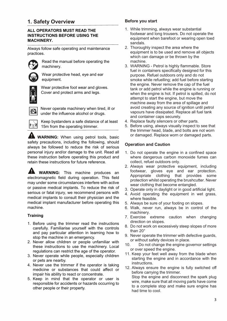
Starting continued:
Warning: Releasing the starting rope suddenly may allow the rope to whip around and cause injury and/or damage the recoil starting mechanism. When starting the engine, firmly grasp the recoil starter grip; do not grasp the starter rope itself. Always control the rope as it rewinds into the housing. 6. Squeeze the throttle lever to switch the lift up lever to the “RUNNING” (engine idle speed) position, and then release the throttle lever back to fully “CLOSED” (engine idle speed) Note: Should the engine fail to start, do not try the recoil start many times with the lift up lever to the “STARTING” position or the choke lever to the “CLOSED” position. This will cause the fuel to flood into the cylinder and make starting even more difficult. In this case, set the lift up lever to the “RUNNING” position or the choke lever to the “OPEN” position. And then, repeat the starting. After starting, vary the engine speed a few times, by operating the throttle lever to draw out the remaining air in the carburettor. Note: Allow sufficient warm-up time to prevent engine damage and run the engine smoothly. The engine should be run at idle speed for a few minutes to allow it to warm up before applying a load. This will allow oil to reach engine parts, and allow piston clearance to reach design specifications.
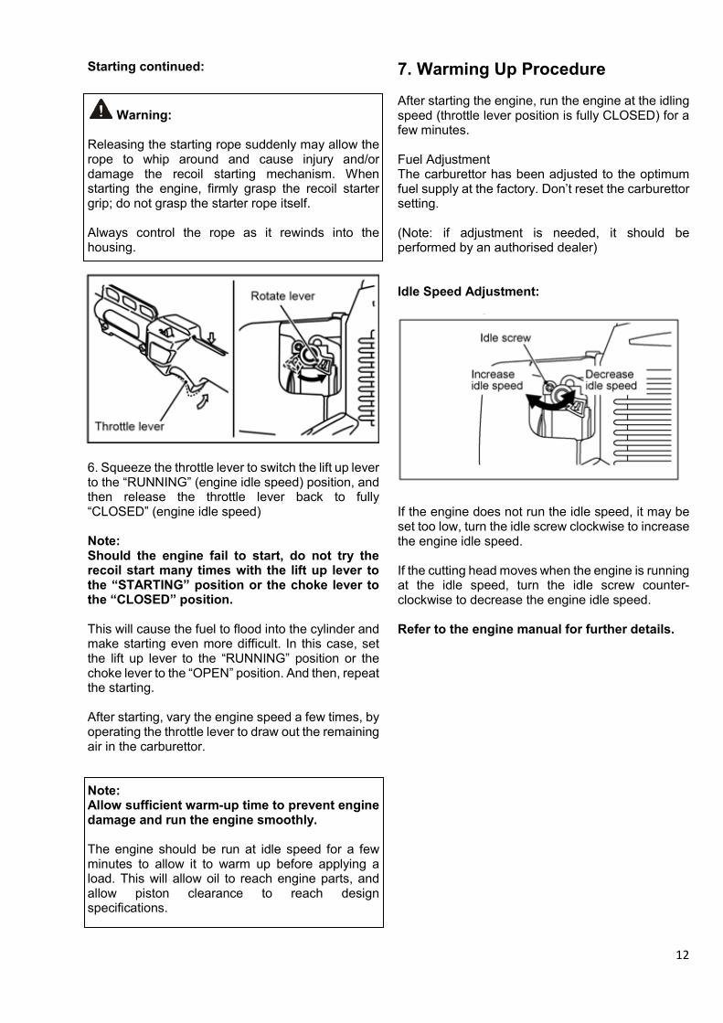
7. Warming Up Procedure After starting the engine, run the engine at the idling speed (throttle lever position is fully CLOSED) for a few minutes. Fuel Adjustment The carburettor has been adjusted to the optimum fuel supply at the factory. Don’t reset the carburettor setting. (Note: if adjustment is needed, it should be performed by an authorised dealer) Idle Speed Adjustment: If the engine does not run the idle speed, it may be set too low, turn the idle screw clockwise to increase the engine idle speed. If the cutting head moves when the engine is running at the idle speed, turn the idle screw counter-clockwise to decrease the engine idle speed. Refer to the engine manual for further details.

13
Throttle lever
Engine switch
8. Stopping Move the throttle lever on the equipment to the fully CLOSED (engine idle speed) position, and the engine running at idle speed. Turn the engine switch to the “O” (stopping) position. Note: Suddenly stopping engine from highspeed operation can cause engine damage. Reduce engine speed to idle speed for one minute before shutting engine off after high-speed, full-load operation. Emergency Stop: Turn the engine switch to the “O” (stopping) position. Note: -Never stop the engine by closing the choke lever. -Never stop the engine during operation while running above idle speed. -Shut off the engine and allow it to cool before transporting or storing the unit. -Do not put the unit on dry grass or near any flammable object unless the engine is cold or cooled down.
9. Maintenance Air Cleaner Service Clean the air cleaner element every 20 hours. -Remove the air cleaner cap from the air cleaner case by removing the air cleaner cap screw. -Remove the element from the air cleaner case. -Wash the element in detergent and water and dry it thoroughly. -Reinstall the element in the air cleaner case and reinstall the air cleaner and tighten the screw. Note: Improper element cleaning can result in engine damage. Do not use compressed air to clean or dry element. Always clean element with an approved high flash point solvent only. Never use petrol. Do not operate engine with air filter parts removed. Fuel Tank Cap Service A breather passage is incorporated in the tank cap. If the breather passage is clogged, the fuel will not flow into the carburettor, causing problems with starting or running the engine. At the same time, make sure that the base of the breather assembly is fitted firmly into the groove inside the tank cap as shown.
Breather passage
Tank cap
Fuel tank
Breather assembly

14
Maintenance continued:
Fuel Filter Service Every 20 hours of operation -Pull the fuel filter out from the fuel tank. -Clean the fuel filter in a bath of high flashpoint solvent. -Dry the fuel filter and reinstall it into the fuel tank. Note: If a fuel still does not flow well after the cleaning, replace the fuel filter with new one.
Warning: Many solvents are highly flammable and may cause serious burns. Improper use of solvents can result in fi re or an explosion. Do not use petrol or low flash-point solvents to clean the fuel filter. Clean only in a well-ventilated area away from sources of sparks or flame, including any appliances with a pilot light. Spark Plug Service
Every 50 hours of operation -Take the spark plug cap with fingers and pull it up. -Remove the spark plug by using a suitable plug wrench. -Clean the electrodes by scraping or with a wire brush to remove carbon deposits and wetness. -Inspect for cracked porcelain or other wear and damage. Replace the spark plug with a new one if necessary.
Spark Plug Maintenance continued -Check the spark plug gap and reset it if necessary. The gap must be between 0.6 and 0.7mm. To change the gap, bend only side-electrode, using a spark plug tool. -Install and tighten the spark plug to 14N·m (1.4kgf·m). -Fit the spark plug cap on the spark plug securely. -Pull up the spark plug cap lightly to make sure of the installation of the spark plug cap. Recommended spark plug: NGK BPMR7A Spark Arrester Service
Every 50 hours of operation -Remove the spark arrester from the exhaust hole of muffler -Clean deposits from the spark arrester screen by brushing it. -Install the spark arrester. Carbon Removal of Engine Internal Parts Every 50 hours of operation These items must be performed with proper tools. See your authorised dealer for service.
Warning: Petrol is a toxic substance. Dispose of petrol properly. Contact your local authorities for approved disposal methods.
Fuel Filter
Electrodes
Spark plug gap
Spark arrester
Muffler

15
10. Storage
Engine to be stored over 30 days should be completely drained of fuel to prevent gum deposits forming on essential carburettor parts fuel filter and fuel tank. -Clean the engine and the brushcutter. -Remove all the fuel from the tank and run the engine at idling to use up the fuel in the carburettor. -Remove the spark plug, pour in 0.5 ml of new 2-stroke engine oil through the plug hole, pull the recoil starter grip several times, and reinstall the spark plug. -Slowly pull the recoil starter grip until resistance is felt. -Store the engine in a clean and dry place.
11. Troubleshooting Guide
For an authorised repairer see the Cobra dealer locator – cobragarden.co.uk
Symptom Probable cause Remedy Engine won't start or output is low
Insufficient compression
Faulty piston, cylinder and piston ring See an authorised repairer Loose spark plug Tighten properly. Loose cylinder bolts
No fuel to combustion chamber
No fuel in fuel tank Fill fuel tank. Blocked fuel filter or tube Clean. Blocked air vent in tank cap Faulty carburettor See an authorised repairer
Spark plug fouled by fuel
Over-rich fuel/air mixture
Turn lift up lever to "Starting" position. Rotate engine with spark plug removed to discharge excess fuel. Clean the spark plug.
Clogged air cleaner Clean Faulty carburettor See an authorised repairer Incorrect grade/type of fuel Change petrol. Water in fuel
Replace spark plug. Faulty spark plug No spark or weak spark
Faulty ignition coil See an authorised repairer Engine switch left in "O"(STOP) position
Turn the engine switch to "START" position.
Clogged air cleaner Clean Low output Engine
overheats Recoil starter or cooling air path clogged with dirt
See an authorised repairer
Carbon built--up in combustion chamber Poor ventilation around engine Select a better location.
Lubricator Plug hole

16
12. Warranty This product is warranted in accordance with legal regulations for a 24 month period when used non- commercially and 12 months when used commercially, this is effective from the date of purchase by the first user.
This warranty covers all material or production failures, it does not include: defects from normal wear and tear, parts such as, bearings, brushes, cables, air cleaning elements, brake pad, clutch disc, tyre, wheel, recoil starter rope, belts, cutter blades, plugs, lubricant oils and grease or accessories. Damage or defects resulting from abuse, accidents or alterations, natural fading of painted or plated surfaces, sheet peeling and other natural deterioration. Any damage that occurs from the use of non-genuine Cobra parts will not be covered. We reserve the right to reject any claim where the purchase cannot be verified or when it is clear that the product was not maintained properly. (Clean ventilation slots, carbon brushes and serviced regularly) Expenses incidental to the warranty claim that are not covered; -Compensation for loss of time, commercial loss or rental costs of substitute product. -Costs incurred for transportation to and from the dealership. Any damage that occurs from the following will not be covered; exposure of the product to smoke and soot, chemical agents, bird droppings or other animal waste, seawater, sea breeze, salt or other environmental phenomena. Any damage resulting from operating methods other than those indicated in the owner’s manual will not be covered. Your purchase receipt must be kept as proof for date of purchase. Your un-dismantled machinery must be returned to your dealer in an acceptably clean state, accompanied by your proof of purchase. Please Register Your Cobra If your dealer did not collect registration information from you, please take a few minutes and register your purchase with Cobra. You can register by completing and mailing the registration card that should be in the box or by going online to: www.cobragarden.co.uk and clicking on Product Registration. Before using the machinery, all operators must read this manual 13. Environment Should your machine need replacement after extended use, do not put it in the domestic waste but dispose of it in an environmentally safe way.

17
14. EC-DECLARATION OF CONFORMITY
EC Declaration of Conformity
We herewith declare,
Cobra Garden Machinery
Henton & Chattell Ltd, London Road, Nottingham NG2 3HW United Kingdom
that the following machine complies with the appropriate basic safety and health requirements of the EC Directive based on its design and type, as brought into circulation by us.
In case of alteration of the machine, not agreed upon by us, this declaration will lose its validity
Machine Description: Brush cutter
Machine Type: BC270KB (PNBC270K) BC270K (PNBC270K) BC350KB (PNBC350KB) BC350K (PNBC350K) BC450K (PNBC450K)
Displacement BC270 -26.3 cm3 BC350 - 34.4 cm3 BC45K -45.4 cm3
Measured sound power level: 95 dB(A)
Guaranteed sound power level: 110 dB(A)
Name of Notified Body Intertek Testing Services Ltd.,
Building No 86 1198 Qinzhou Road North Shanghai, 200233
Applicable EC Directives EC Machinery Directive:2006/42/EC
EC Directive of Electromagnetic Compatibility:2004/108/EC
EC Directive of noise emission: 2005/88/EC
Applicable Harmonized Standards EN ISO 11806
EN ISO 14982
Authorized Signature/Date
Peter J. Chaloner 18th April 2018
Title of Signatory Managing Director
Name and address of the person authorised to compile the technical file
Cobra Garden Machinery
Henton & Chattell Ltd, London Road, Nottingham NG2 3HW United Kingdom