
Automationsystems Drive solutions Controls Inverters Motors ...
Upload
independentCategory
view
0download
0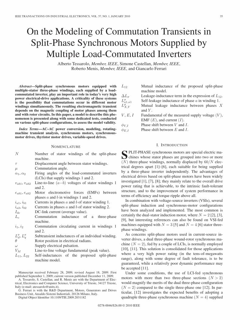
IEEE TRANSACTIONS ON INDUSTRIAL ELECTRONICS, VOL. 57, NO. 1, JANUARY 2010 35
On the Modeling of Commutation Transients inSplit-Phase Synchronous Motors Supplied by
Multiple Load-Commutated InvertersAlberto Tessarolo, Member, IEEE, Simone Castellan, Member, IEEE,
Roberto Menis, Member, IEEE, and Giancarlo Ferrari
Abstract—Split-phase synchronous motors equipped withmultiple-stator three-phase windings, each supplied by a load-commutated inverter, play an important role in today’s very highpower electrical-drive applications. A criticality of these systemsis the possibility that commutations occur in different motorwindings simultaneously. The resulting electromagnetic transientdepends on the magnetic coupling of motor phases among themand with rotor circuits. In this paper, a model to describe this phe-nomenon is presented along with some dedicated tests, conductedon various split-phase configurations, to assess the model validity.
Index Terms—AC–AC power conversion, modeling, rotating-machine transient analysis, synchronous motors, synchronous-motor drives, thyristor motor drives, variable-speed drives.
NOMENCLATURE
N Number of stator windings of the split-phasemachine.
τ Displacement angle between stator windings.μ Commutation angle.α1, α2 Firing angles of the load-commutated inverters
(LCIs) that supply windings 1 and 2.vab1, vab2 Line-to-line (a−b) voltages of stator windings 1
and 2.eab1, eab2 Motor electromotive forces (EMFs) between
phases a and b in windings 1 and 2.ia1, ib1 Currents in phases a and b of stator winding 1.ia2, ib2 Currents in phases a and b of stator winding 2.Idc DC-link current (average value).Lc Commutation inductance of a three-phase
machine.i1, i2 Commutation circulating current in windings 1
and 2.L′′
d, L′′q Subtransient inductances of an individual winding.
θ Rotor position in electrical radians.ω Supply electrical pulsation.VM Line-to-line voltage fundamental (peak value).L11, L22 Self-inductances of the proposed split-phase
machine model.
Manuscript received February 28, 2009; revised August 18, 2009. Firstpublished September 1, 2009; current version published December 11, 2009.
A. Tessarolo, S. Castellan, and R. Menis are with the Department of Elec-trical, Electronics and Computer Science, University of Trieste, 34127 Trieste,Italy (e-mail: [email protected]).
G. Ferrari is with the R&D Department, Motors, Generators and DrivesBusiness Unit, Ansaldo Sistemi Industriali, 20126 Milano, Italy.
Digital Object Identifier 10.1109/TIE.2009.2031182
L12 Mutual inductance of the proposed split-phasemachine model.
ΔLσ Leakage-inductance term in the expression of L12.Lσ
a1,a1 Self-leakage inductance of phase a in winding 1.Lσ
X,Y Mutual leakage inductance between phases Xand Y .
V , E, I Fundamental of the measured supply voltage (V ),EMF (E), and current (I).
φV,I Phase shift between V and I .φE,I Phase shift between E and I .
I. INTRODUCTION
S PLIT-PHASE synchronous motors are special electric ma-chines whose stator phases are grouped into two or more
(N) three-phase windings, normally displaced by 60/N elec-trical degrees apart [1]–[6], each suitable for being suppliedby a three-phase inverter independently. The advantages ofelectrical drives based on split-phase motors have been widelyinvestigated [1], [7], [8]; they mainly relate to the overall drivepower rating that is achievable, to the intrinsic fault-tolerantstructure, and to the improvement of system performance interms of efficiency and torque ripple above all.
In combination with voltage-source inverters (VSIs), severalsplit-phase induction and synchronous-motor configurationshave been analyzed and implemented. The most common iscertainly the dual-stator induction motor, where N = 2 [2], [3],[9], but interesting references can also be found on VSI-fedmachines equipped with N = 3 [5] and N = 4 [6] stator three-phase windings.
As concerns split-phase motors used in current-source in-verter drives, a dual three-phase wound-rotor synchronous ma-chine (N = 2), fed by a couple of LCIs, is normally employed[10], [11]. This solution is consolidated for those applicationswhere a very high power rating (in the tens-of-megawattsrange), along with some degree of fault tolerance, is to beguaranteed, while a relatively poor dynamic performance maybe accepted [11].
Under some conditions, the use of LCI-fed synchronousmotors with more than two three-phase sections (N > 2)would magnify the merits of the dual three-phase configuration(N = 2) compared to the single three-phase one [12]. In par-ticular, [12] investigates the expected benefits of adopting aquadruple three-phase synchronous machine (N = 4) supplied
0278-0046/$26.00 © 2010 IEEE
36 IEEE TRANSACTIONS ON INDUSTRIAL ELECTRONICS, VOL. 57, NO. 1, JANUARY 2010
Fig. 1. Stator-phase arrangement in a split-phase motor with N windings,each composed of a three-phase symmetrical set (a, b, c).
by four LCIs in terms of power factor, efficiency, and outputtorque quality.
As better explained in Section II, the main drawback ofincreasing N in LCI-fed synchronous machines is that theminimum time interval between two commutations diminishesas N grows. This leads to the possibility that, during overloads,as well as in the case of absent or faulty synchronizationamong the inverters, commutations that occur in different motorwindings may overlap [14]. The electromagnetic transient thatoriginates in this case cannot be studied through the modelsproposed in the literature for normal commutation [13] dueto the close and complex interactions between simultaneouslycommutating phases, both among them and with rotor circuits.
This electromagnetic transient is an issue that has beeninvestigated in [14] in detail. As a result, it has been shownhow the split-phase motor behavior during overlapping com-mutations can be described through a simple model, whichmay be expressed in either circuit or analytical form. In thispaper, such a model will be briefly discussed (Section III)and validated through measurements collected on a real dualLCI synchronous-motor drive (Section IV). Finally, the resultsof some dedicated tests on a prototype synchronous machinewill be presented (Section V) to assess the model validity invarious split-phase winding configurations and for differentrotor positions.
II. SPLIT-PHASE MACHINES AND
OVERLAPPING-COMMUTATION ISSUE
The schematic of a split-phase stator system, composed ofN three-phase windings, is shown in Fig. 1. Each stator wind-ing comprises three phases (a, b, c) shifted by 2π/3 electricalradians. The N windings are, in turn, displaced by
τ = π/(3N) (1)
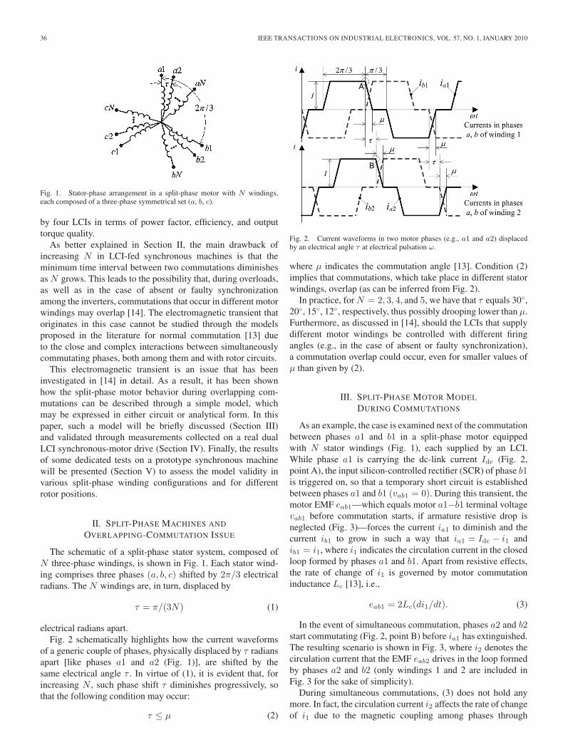
electrical radians apart.Fig. 2 schematically highlights how the current waveforms
of a generic couple of phases, physically displaced by τ radiansapart [like phases a1 and a2 (Fig. 1)], are shifted by thesame electrical angle τ . In virtue of (1), it is evident that, forincreasing N , such phase shift τ diminishes progressively, sothat the following condition may occur:
τ ≤ μ (2)
Fig. 2. Current waveforms in two motor phases (e.g., a1 and a2) displacedby an electrical angle τ at electrical pulsation ω.
where μ indicates the commutation angle [13]. Condition (2)implies that commutations, which take place in different statorwindings, overlap (as can be inferred from Fig. 2).
In practice, for N = 2, 3, 4, and 5, we have that τ equals 30◦,20◦, 15◦, 12◦, respectively, thus possibly drooping lower than μ.Furthermore, as discussed in [14], should the LCIs that supplydifferent motor windings be controlled with different firingangles (e.g., in the case of absent or faulty synchronization),a commutation overlap could occur, even for smaller values ofμ than given by (2).
III. SPLIT-PHASE MOTOR MODEL
DURING COMMUTATIONS
As an example, the case is examined next of the commutationbetween phases a1 and b1 in a split-phase motor equippedwith N stator windings (Fig. 1), each supplied by an LCI.While phase a1 is carrying the dc-link current Idc (Fig. 2,point A), the input silicon-controlled rectifier (SCR) of phase b1is triggered on, so that a temporary short circuit is establishedbetween phases a1 and b1 (vab1 = 0). During this transient, themotor EMF eab1—which equals motor a1−b1 terminal voltagevab1 before commutation starts, if armature resistive drop isneglected (Fig. 3)—forces the current ia1 to diminish and thecurrent ib1 to grow in such a way that ia1 = Idc − i1 andib1 = i1, where i1 indicates the circulation current in the closedloop formed by phases a1 and b1. Apart from resistive effects,the rate of change of i1 is governed by motor commutationinductance Lc [13], i.e.,
eab1 = 2Lc(di1/dt). (3)
In the event of simultaneous commutation, phases a2 and b2start commutating (Fig. 2, point B) before ia1 has extinguished.The resulting scenario is shown in Fig. 3, where i2 denotes thecirculation current that the EMF eab2 drives in the loop formedby phases a2 and b2 (only windings 1 and 2 are included inFig. 3 for the sake of simplicity).
During simultaneous commutations, (3) does not hold anymore. In fact, the circulation current i2 affects the rate of changeof i1 due to the magnetic coupling among phases through
TESSAROLO et al.: MODELING OF TRANSIENTS IN SYNCHRONOUS MOTORS SUPPLIED BY LCIs 37
Fig. 3. Simultaneous commutation of a1−b1 and a2−b2 phase pairs. Thethin lines and empty SCRs denote the paths where no current flows.
Fig. 4. Equivalent circuit form of the model.
stator mutual inductances and vice versa. Furthermore, thepresence of the rotor and its electric circuits—a field winding(f), a damper (kd) on the d-axis, and a damper (kq) on theq-axis—needs to be taken into account.
The analytical formalization of the phenomenon is reportedin [14], where the differential equations of a split-phase ma-chine during single and overlapping commutations are alge-braically manipulated, leading to a simple model that describeshow i1 and i2 evolve during the transient. The model represen-tation in terms of equivalent circuit is shown in Fig. 4.
Explicit expressions for parameters L11, L22, and L12, whichappear in the circuit, are given by (4)–(6) in terms of subtran-sient inductances L′′
d and L′′q (of an individual three-phase stator
winding) and of rotor position θ, measured in electrical radianswith respect to the magnetic axis of phase a1 (Fig. 3)
L11 =(L′′
d + L′′q
)+
(L′′
d − L′′q
)cos [2(θ + π/6)] (4)
L22 =(L′′
d + L′′q
)+
(L′′
d − L′′q
)cos [2(θ − τ + π/6)] (5)
L12 =(L′′
d + L′′q
)cos(τ)
+(L′′
d − L′′q
)cos [2(θ − τ/2 + π/6)] + ΔLσ. (6)
Furthermore, (6) includes a leakage inductance term ΔLσ ,whose expression has been derived as follows [14]:
ΔLσ =2Lσa1,a2−Lσ
a1,b2−Lσb1,a2−2 cos(τ)
(Lσ
a1,a1−Lσa1,b1
)
(7)
where Lσa1,a1 denotes the self-leakage inductance of a sta-
tor phase and LσX,Y denotes the mutual leakage inductance
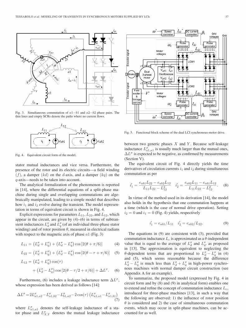
Fig. 5. Functional block scheme of the dual LCI synchronous-motor drive.
between two generic phases X and Y . Because self-leakageinductance Lσ
a1,a1 is usually much larger than the mutual ones,ΔLσ is expected to be negative, as confirmed by measurements(Section V).
The equivalent circuit of Fig. 4 directly yields the timederivatives of circulation currents i1 and i2 during simultaneouscommutation as per
i′1 =eab1L22 − eab2L12
L11L22 − L212
i′2 =eab2L11 − eab1L12
L11L22 − L212
. (8)
In virtue of the method used in its derivation [14], the modelalso holds in the hypothesis that one commutation happens ata time (which is the case of normal drive operation). Settingi2 = 0 and i1 = 0 (Fig. 4) yields, respectively
i′1 = eab1/L11 i′2 = eab2/L22. (9)
The equations in (9) are consistent with (3), provided thatcommutation inductance Lc is approximated as a θ-independentvalue that is equal to the average of L′′
d and L′′q, as proposed
in [13]. The approximation is equivalent to neglecting theθ-dependent terms that are proportional to L′′
d − L′′q in (4)
and (5), which seems reasonable because the differenceL′′
d − L′′q is much less than L′′
d + L′′q in high-power synchro-
nous machines with normal damper circuit construction (seeAppendix A for an example).
To summarize, the proposed model (expressed by Fig. 4 incircuit form and by (8) and (9) in analytical form) enables oneto extend and refine the concept of commutation inductance Lc,introduced for three-phase machines [13], in such a way thatthe following are observed: 1) the influence of rotor positionθ is considered and 2) the case of simultaneous commutationevents, which may occur in split-phase machines, can be ac-counted for as well.

38 IEEE TRANSACTIONS ON INDUSTRIAL ELECTRONICS, VOL. 57, NO. 1, JANUARY 2010
Fig. 6. Main drive components. (a) Dual three-phase synchronous motor. (b) Dual-converter power electronics. (c) Control boards.
IV. EXAMPLE OF APPLICATION TO
COMMUTATION-TRANSIENT ANALYSIS
In [14], a complete drive system, including a dual three-phase synchronous motor supplied by two LCIs, is accuratelysimulated in the Matlab/Simulink environment under different(both normal and abnormal) operating conditions; numericalsimulation results are then used to show how the motor transientbehavior during commutations can be very well predicted bythe simple model described previously.
To further assess the model validity and to illustrate itspractical applications, measurements collected on a real drivewill be reported hereinafter for comparison with model outputs.
A. Drive System Description
A schematic and some photographs of the equipment usedare shown in Figs. 5 and 6; the nameplate ratings of the singlecomponents can be found in Appendix A.
The equipment is mainly composed of two SCR inverters(LCI#1 and LCI#2) that supply the stator windings of a dualthree-phase synchronous motor (N = 2 and τ = π/6). The twoLCIs are synchronized to the respective stator windings withfiring angles (α1 and α2) that can be manually and indepen-dently adjusted. The two grid-side SCR rectifiers are insteadsynchronized to the grid voltages with firing angles (β1 and β2)that are the outputs of dc-link current controllers. The referencedc-link current (I∗dc), in turn, results from a speed controllerthat regulates the motor speed to the desired value (ω∗). Finally,the motor voltage is maintained at its commanded value (V ∗)acting on the field excitation supply.
A digital oscilloscope is used to record phase currents ia1
and ia2 and line-to-line voltages vab1 and vab2 with a samplinginterval of 10−7 s.
B. Normal-Commutation Analysis
To assess (9), the described drive is operated normally,setting the two firing angles α1 and α2 at the same value.For example, Fig. 7(a) shows the waveforms of ia1, ia2 andvab1, vab2, recorded by the digital oscilloscope, when α1 =α2 = 125◦. The operating point is also characterized by amotor supply pulsation ω = 314 rad/s, a line-to-line voltagefundamental peak value VM = 501 V, and an average dc-linkcurrent Idc = 65 A.
Fig. 7(a) shows that both voltage and current waveformsof the two windings are shifted by τ = π/6 electrical radians
Fig. 7. Normal drive operation with equal firing angles α1 = α2 = 125◦.(a) Recorded phase currents ia1 and ia2 and recorded line-to-line voltagesvab1 and vab2; (b) Zoomed-in view around point C, where phase a1 startscommutating.
apart; the commutation of phase a1 starts (at point C) with adelay of α1 electrical radians from the zero-crossing instant (A)of voltage vab1; similarly, the commutation of phase a2 starts(D) with a delay of α2 electrical radians from the zero-crossinginstant (B) of voltage vab2.
By zooming on point C, the normal-commutation transientcan be seen in more detail [Fig. 7(b)]. This enables one toappreciate how the rate of increase of ia1 is well predictedthrough (9), where i′1 = −i′a1 (Section III), so that
i′a1 = −eab1/L11. (10)
In fact, since the machine under test has L′′d∼= L′′
q , parametersL11 and L22 are almost independent of θ, and for any rotorposition, their measured value is (Appendix A)
L11∼= L22
∼= L′′q + L′′
q = 1.72 × 10⁻³ H. (11)

TESSAROLO et al.: MODELING OF TRANSIENTS IN SYNCHRONOUS MOTORS SUPPLIED BY LCIs 39
Fig. 8. Drive operation with different firing angles (α1 = 155◦ and α1 =128◦). (a) Recorded phase currents ia1 and ia2 and recorded line-to-linevoltages vab1 and vab2. (b) Zoomed-in view around point A, showing asimultaneous commutation transient that involves phases a1−b1 and a2−b2.
Concerning eab1, it follows vab1, except for commutationvoltage dips (Section III). Hence, from Fig. 7(a), one can write
eab1∼= −VM sin(α1). (12)
From (10)–(12), i′a1 = 2.39 × 10⁵ A/s [Fig. 7(b)] is socalculated.
C. Overlapping-Commutation Analysis
In order to illustrate the application of (8), the drive is oper-ated with different firing angles α1 and α2. In particular, whileα1 is kept at 155◦, α2 is progressively diminished. The effect ofdecreasing α2 is that, as the phase shift τ = π/6 between vab1
and vab2 remains practically unchanged, the current waveformof ia2 “slides” to the left with respect to ia1 [Fig. 7(a)], sothat point D approaches point C. For a given value of α1
(such that α1 − α2∼= τ ), the commutation transients involving
phases a1−b1 and a2−b2 overlap. Such a situation is shownin Fig. 8(a), which refers to the case where α1 and α2 equal155◦ and 128◦, respectively. The drive operating point is furthercharacterized by a motor supply pulsation ω = 314 rad/s, a line-to-line voltage fundamental peak value VM = 540 V, and anaverage dc-link current Idc = 51 A.
By zooming on point A, the simultaneous commutationtransient appears in more detail [Fig. 8(b)].
At instant t0, phase a1 starts commutating first. While ia1 isstill growing, namely, at instant t1, phase a2 starts commutat-ing, too. Therefore, between t1 and t2, both a1−b1 and a2−b2phase pairs are commutating simultaneously. During this in-terval, it is evident from Fig. 8(b) how a2−b2 commutationcurrent strongly affects the dynamics of a1−b1 commutationdue to the mutual magnetic couplings between phases [14].
The influence is such that the slope of ia1 is even reversed(its time derivative changes to a negative value) until a2−b2commutation ends, i.e., until t2. After this instant, current ia1
continues increasing with nearly the same time derivative thatit had for t0 < t < t1 up to the end of the commutation (t3).
As shown in Fig. 8(b), the dynamics of the overall commuta-tion transient can be well predicted by the proposed model. Infact, during intervals t0−t1 and t2−t3, when only one winding(i.e., winding 1) commutates, the first of (9) holds, with
i′a1 = i′1 eab1∼= −VM sin(α1) L11
∼= 1.72 × 10³ H (13)
so the commutation current derivative is calculated as
i′a1 = 1.33 × 10⁵ A/s (t0 < t < t1, t2 < t < t3). (14)
During t1−t2 interval, when both windings are commutatingtogether, (8) becomes applicable instead, with
i′a1 = i′1 i′a2 = i′2
eab1∼= − VM sin(α1) eab2
∼= −VM sin(α2)
L11∼=L22
∼= 1.72 × 10³ H L12∼= 1.24 × 10³ H. (15)
The numeric evaluation of (8) with the aforementioned datayields
i′a1 = −9.51 × 10⁴ A/s i′a2 = 3.16 × 10⁵ A/s (t1 < t < t2).(16)
The slopes given by (14) and (16) are those used to plot thediagrams “from calculation” in Fig. 8(b).
D. General Remarks
In addition to confirming the proposed model validity, theexperiments reported in this section demonstrate that, in split-phase machines supplied by multiple LCIs, different statorwindings may simultaneously commutate. It is shown that suchan event does not necessarily result in either a commutation lossor a fault but strongly affects the dynamics of the commutationtransient. In particular, as it can be theoretically predicted [14],it may happen that the current in one of the two simultaneouslycommutating windings temporarily reverses. This leads to aremarkable increase in the overall time interval required forcommutations to complete and, consequently, to a reduction inthe commutation margin angle [13].
The simple model proposed in this paper is able to predictthe split-phase machine behavior during both normal- andoverlapping-commutation transients with adequate accuracy.The use of such a simple analytical or circuit model may repre-sent a useful alternative to the complete modeling and numericsimulation of the entire drive system [12], [14], particularlywhen a very large amount of commutation-transient scenariosneed to be investigated in the drive design stage.
V. EXPERIMENTAL RESULTS ON MODEL
PARAMETER CALCULATION
In the previous section, the proposed model has been val-idated against measurements on a real split-phase LCI-fed
40 IEEE TRANSACTIONS ON INDUSTRIAL ELECTRONICS, VOL. 57, NO. 1, JANUARY 2010
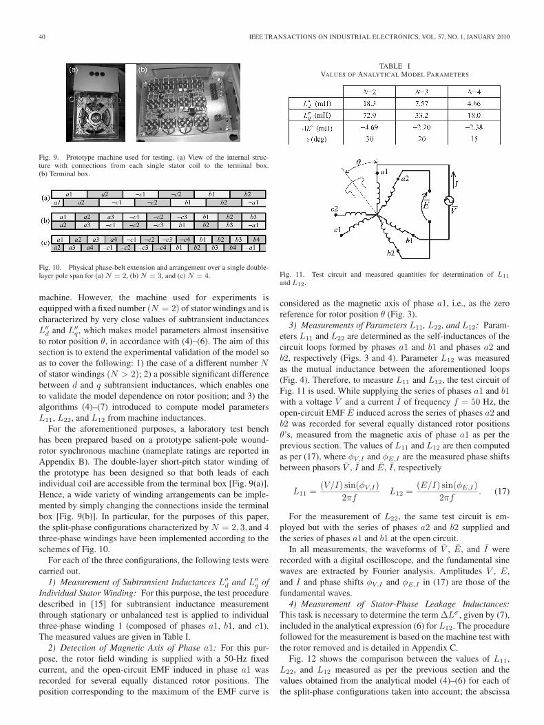
Fig. 9. Prototype machine used for testing. (a) View of the internal struc-ture with connections from each single stator coil to the terminal box.(b) Terminal box.
Fig. 10. Physical phase-belt extension and arrangement over a single double-layer pole span for (a) N = 2, (b) N = 3, and (c) N = 4.
machine. However, the machine used for experiments isequipped with a fixed number (N = 2) of stator windings and ischaracterized by very close values of subtransient inductancesL′′
d and L′′q, which makes model parameters almost insensitive
to rotor position θ, in accordance with (4)–(6). The aim of thissection is to extend the experimental validation of the model soas to cover the following: 1) the case of a different number Nof stator windings (N > 2); 2) a possible significant differencebetween d and q subtransient inductances, which enables oneto validate the model dependence on rotor position; and 3) thealgorithms (4)–(7) introduced to compute model parametersL11, L22, and L12 from machine inductances.
For the aforementioned purposes, a laboratory test benchhas been prepared based on a prototype salient-pole wound-rotor synchronous machine (nameplate ratings are reported inAppendix B). The double-layer short-pitch stator winding ofthe prototype has been designed so that both leads of eachindividual coil are accessible from the terminal box [Fig. 9(a)].Hence, a wide variety of winding arrangements can be imple-mented by simply changing the connections inside the terminalbox [Fig. 9(b)]. In particular, for the purposes of this paper,the split-phase configurations characterized by N = 2, 3, and 4three-phase windings have been implemented according to theschemes of Fig. 10.
For each of the three configurations, the following tests werecarried out.
1) Measurement of Subtransient Inductances L′′d and L′′
q ofIndividual Stator Winding: For this purpose, the test proceduredescribed in [15] for subtransient inductance measurementthrough stationary or unbalanced test is applied to individualthree-phase winding 1 (composed of phases a1, b1, and c1).The measured values are given in Table I.
2) Detection of Magnetic Axis of Phase a1: For this pur-pose, the rotor field winding is supplied with a 50-Hz fixedcurrent, and the open-circuit EMF induced in phase a1 wasrecorded for several equally distanced rotor positions. Theposition corresponding to the maximum of the EMF curve is
TABLE IVALUES OF ANALYTICAL MODEL PARAMETERS
Fig. 11. Test circuit and measured quantities for determination of L11
and L12.
considered as the magnetic axis of phase a1, i.e., as the zeroreference for rotor position θ (Fig. 3).
3) Measurements of Parameters L11, L22, and L12: Param-eters L11 and L22 are determined as the self-inductances of thecircuit loops formed by phases a1 and b1 and phases a2 andb2, respectively (Figs. 3 and 4). Parameter L12 was measuredas the mutual inductance between the aforementioned loops(Fig. 4). Therefore, to measure L11 and L12, the test circuit ofFig. 11 is used. While supplying the series of phases a1 and b1with a voltage V and a current I of frequency f = 50 Hz, theopen-circuit EMF E induced across the series of phases a2 andb2 was recorded for several equally distanced rotor positionsθ’s, measured from the magnetic axis of phase a1 as per theprevious section. The values of L11 and L12 are then computedas per (17), where φV,I and φE,I are the measured phase shiftsbetween phasors V , I and E, I , respectively
L11 =(V/I) sin(φV,I)
2πfL12 =
(E/I) sin(φE,I)2πf
. (17)
For the measurement of L22, the same test circuit is em-ployed but with the series of phases a2 and b2 supplied andthe series of phases a1 and b1 at the open circuit.
In all measurements, the waveforms of V , E, and I wererecorded with a digital oscilloscope, and the fundamental sinewaves are extracted by Fourier analysis. Amplitudes V , E,and I and phase shifts φV,I and φE,I in (17) are those of thefundamental waves.
4) Measurement of Stator-Phase Leakage Inductances:This task is necessary to determine the term ΔLσ , given by (7),included in the analytical expression (6) for L12. The procedurefollowed for the measurement is based on the machine test withthe rotor removed and is detailed in Appendix C.
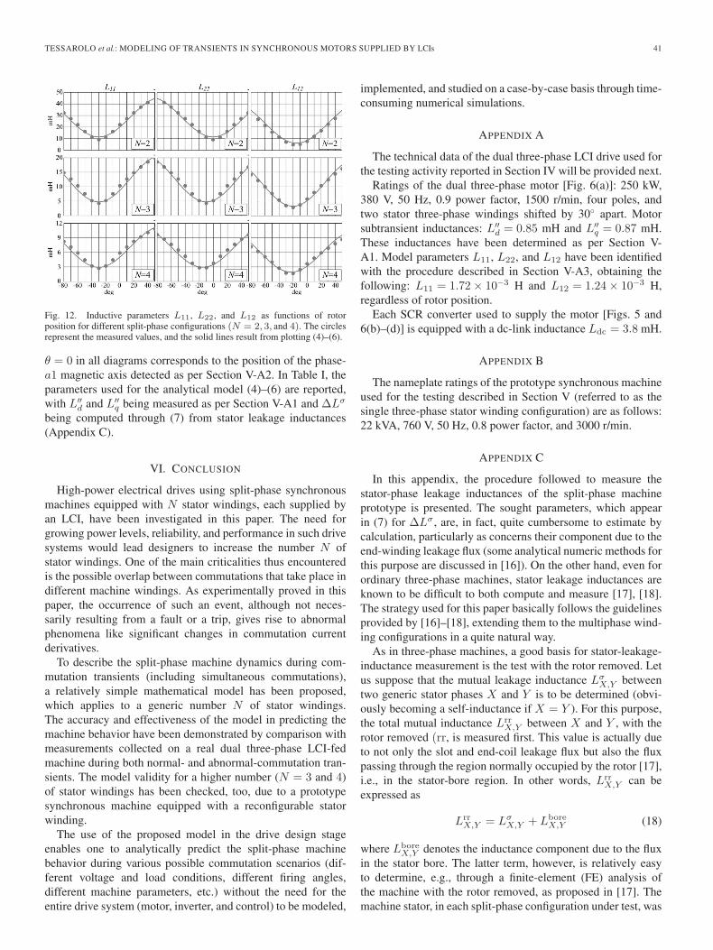
Fig. 12 shows the comparison between the values of L11,L22, and L12 measured as per the previous section and thevalues obtained from the analytical model (4)–(6) for each ofthe split-phase configurations taken into account; the abscissa
TESSAROLO et al.: MODELING OF TRANSIENTS IN SYNCHRONOUS MOTORS SUPPLIED BY LCIs 41
Fig. 12. Inductive parameters L11, L22, and L12 as functions of rotorposition for different split-phase configurations (N = 2, 3, and 4). The circlesrepresent the measured values, and the solid lines result from plotting (4)–(6).
θ = 0 in all diagrams corresponds to the position of the phase-a1 magnetic axis detected as per Section V-A2. In Table I, theparameters used for the analytical model (4)–(6) are reported,with L′′
d and L′′q being measured as per Section V-A1 and ΔLσ
being computed through (7) from stator leakage inductances(Appendix C).
VI. CONCLUSION
High-power electrical drives using split-phase synchronousmachines equipped with N stator windings, each supplied byan LCI, have been investigated in this paper. The need forgrowing power levels, reliability, and performance in such drivesystems would lead designers to increase the number N ofstator windings. One of the main criticalities thus encounteredis the possible overlap between commutations that take place indifferent machine windings. As experimentally proved in thispaper, the occurrence of such an event, although not neces-sarily resulting from a fault or a trip, gives rise to abnormalphenomena like significant changes in commutation currentderivatives.
To describe the split-phase machine dynamics during com-mutation transients (including simultaneous commutations),a relatively simple mathematical model has been proposed,which applies to a generic number N of stator windings.The accuracy and effectiveness of the model in predicting themachine behavior have been demonstrated by comparison withmeasurements collected on a real dual three-phase LCI-fedmachine during both normal- and abnormal-commutation tran-sients. The model validity for a higher number (N = 3 and 4)of stator windings has been checked, too, due to a prototypesynchronous machine equipped with a reconfigurable statorwinding.
The use of the proposed model in the drive design stageenables one to analytically predict the split-phase machinebehavior during various possible commutation scenarios (dif-ferent voltage and load conditions, different firing angles,different machine parameters, etc.) without the need for theentire drive system (motor, inverter, and control) to be modeled,
implemented, and studied on a case-by-case basis through time-consuming numerical simulations.
APPENDIX A
The technical data of the dual three-phase LCI drive used forthe testing activity reported in Section IV will be provided next.
Ratings of the dual three-phase motor [Fig. 6(a)]: 250 kW,380 V, 50 Hz, 0.9 power factor, 1500 r/min, four poles, andtwo stator three-phase windings shifted by 30◦ apart. Motorsubtransient inductances: L′′
d = 0.85 mH and L′′q = 0.87 mH.
These inductances have been determined as per Section V-A1. Model parameters L11, L22, and L12 have been identifiedwith the procedure described in Section V-A3, obtaining thefollowing: L11 = 1.72 × 10⁻³ H and L12 = 1.24 × 10⁻³ H,regardless of rotor position.
Each SCR converter used to supply the motor [Figs. 5 and6(b)–(d)] is equipped with a dc-link inductance Ldc = 3.8 mH.
APPENDIX B
The nameplate ratings of the prototype synchronous machineused for the testing described in Section V (referred to as thesingle three-phase stator winding configuration) are as follows:22 kVA, 760 V, 50 Hz, 0.8 power factor, and 3000 r/min.
APPENDIX C
In this appendix, the procedure followed to measure thestator-phase leakage inductances of the split-phase machineprototype is presented. The sought parameters, which appearin (7) for ΔLσ , are, in fact, quite cumbersome to estimate bycalculation, particularly as concerns their component due to theend-winding leakage flux (some analytical numeric methods forthis purpose are discussed in [16]). On the other hand, even forordinary three-phase machines, stator leakage inductances areknown to be difficult to both compute and measure [17], [18].The strategy used for this paper basically follows the guidelinesprovided by [16]–[18], extending them to the multiphase wind-ing configurations in a quite natural way.
As in three-phase machines, a good basis for stator-leakage-inductance measurement is the test with the rotor removed. Letus suppose that the mutual leakage inductance Lσ
X,Y betweentwo generic stator phases X and Y is to be determined (obvi-ously becoming a self-inductance if X = Y ). For this purpose,the total mutual inductance Lrr
X,Y between X and Y , with therotor removed (rr, is measured first. This value is actually dueto not only the slot and end-coil leakage flux but also the fluxpassing through the region normally occupied by the rotor [17],i.e., in the stator-bore region. In other words, Lrr
X,Y can beexpressed as
LrrX,Y = Lσ
X,Y + LboreX,Y (18)
where LboreX,Y denotes the inductance component due to the flux
in the stator bore. The latter term, however, is relatively easyto determine, e.g., through a finite-element (FE) analysis ofthe machine with the rotor removed, as proposed in [17]. Themachine stator, in each split-phase configuration under test, was
42 IEEE TRANSACTIONS ON INDUSTRIAL ELECTRONICS, VOL. 57, NO. 1, JANUARY 2010
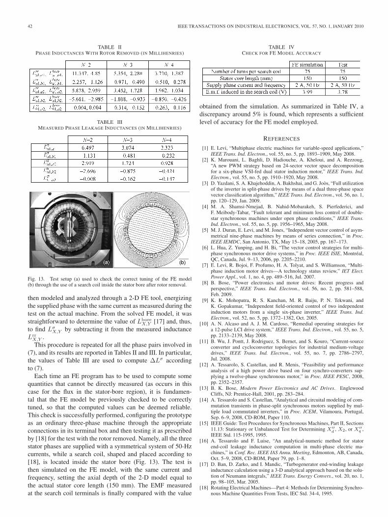
TABLE IIPHASE INDUCTANCES WITH ROTOR REMOVED (IN MILLIHENRIES)
TABLE IIIMEASURED PHASE LEAKAGE INDUCTANCES (IN MILLIHENRIES)
Fig. 13. Test setup (a) used to check the correct tuning of the FE model(b) through the use of a search coil inside the stator bore after rotor removal.
then modeled and analyzed through a 2-D FE tool, energizingthe supplied phase with the same current as measured during thetest on the actual machine. From the solved FE model, it wasstraightforward to determine the value of Lbore
X,Y [17] and, thus,to find Lσ
X,Y by subtracting it from the measured inductanceLrr
X,Y .This procedure is repeated for all the phase pairs involved in
(7), and its results are reported in Tables II and III. In particular,the values of Table III are used to compute ΔLσ accordingto (7).
Each time an FE program has to be used to compute somequantities that cannot be directly measured (as occurs in thiscase for the flux in the stator-bore region), it is fundamen-tal that the FE model be previously checked to be correctlytuned, so that the computed values can be deemed reliable.This check is successfully performed, configuring the prototypeas an ordinary three-phase machine through the appropriateconnections in its terminal box and then testing it as prescribedby [18] for the test with the rotor removed. Namely, all the threestator phases are supplied with a symmetrical system of 50-Hzcurrents, while a search coil, shaped and placed according to[18], is located inside the stator bore (Fig. 13). The test isthen simulated on the FE model, with the same current andfrequency, setting the axial depth of the 2-D model equal tothe actual stator core length (150 mm). The EMF measuredat the search coil terminals is finally compared with the value
TABLE IVCHECK FOR FE MODEL ACCURACY
obtained from the simulation. As summarized in Table IV, adiscrepancy around 5% is found, which represents a sufficientlevel of accuracy for the FE model employed.
REFERENCES
[1] E. Levi, “Multiphase electric machines for variable-speed applications,”IEEE Trans. Ind. Electron., vol. 55, no. 5, pp. 1893–1909, May 2008.
[2] K. Marouani, L. Baghli, D. Hadiouche, A. Kheloui, and A. Rezzoug,“A new PWM strategy based on 24-sector vector space decompositionfor a six-phase VSI-fed dual stator induction motor,” IEEE Trans. Ind.Electron., vol. 55, no. 5, pp. 1910–1920, May 2008.
[3] D. Yazdani, S. A. Khajehoddin, A. Bakhshai, and G. Joòs, “Full utilizationof the inverter in split-phase drives by means of a dual three-phase spacevector classification algorithm,” IEEE Trans. Ind. Electron., vol. 56, no. 1,pp. 120–129, Jan. 2009.
[4] M. A. Shamsi-Nmejad, B. Nahid-Mobarakeh, S. Pierfederici, andF. Meibody-Tabar, “Fault tolerant and minimum loss control of double-star synchronous machines under open phase conditions,” IEEE Trans.Ind. Electron., vol. 55, no. 5, pp. 1956–1965, May 2008.
[5] M. J. Duran, E. Levi, and M. Jones, “Independent vector control of asym-metrical nine-phase machines by means of series connection,” in Proc.IEEE IEMDC, San Antonio, TX, May 15–18, 2005, pp. 167–173.
[6] L. Hua, Z. Yunping, and H. Bi, “The vector control strategies for multi-phase synchronous motor drive systems,” in Proc. IEEE ISIE, Montréal,QC, Canada, Jul. 9–13, 2006, pp. 2205–2210.
[7] E. Levi, R. Bojoi, F. Profumo, H. A. Tolyat, and S. Williamson, “Multi-phase induction motor drives—A technology status review,” IET Elect.Power Appl., vol. 1, no. 4, pp. 489–516, Jul. 2007.
[8] B. Bose, “Power electronics and motor drives: Recent progress andperspective,” IEEE Trans. Ind. Electron., vol. 56, no. 2, pp. 581–588,Feb. 2009.
[9] K. K. Mohopatra, R. S. Kanchan, M. R. Baiju, P. N. Tekwani, andK. Gopakumar, “Independent field-oriented control of two independentinduction motors from a single six-phase inverter,” IEEE Trans. Ind.Electron., vol. 52, no. 5, pp. 1372–1382, Oct. 2005.
[10] A. N. Alcaso and A. J. M. Cardoso, “Remedial operating strategies fora 12-pulse LCI drive system,” IEEE Trans. Ind. Electron., vol. 55, no. 5,pp. 2133–2139, May 2008.
[11] B. Wu, J. Pontt, J. Rodriguez, S. Bernet, and S. Kouro, “Current-sourceconverter and cycloconverter topologies for industrial medium-voltagedrives,” IEEE Trans. Ind. Electron., vol. 55, no. 7, pp. 2786–2797,Jul. 2008.
[12] A. Tessarolo, S. Castellan, and R. Menis, “Feasibility and performanceanalysis of a high power drive based on four synchro-converters sup-plying a twelve-phase synchronous motor,” in Proc. IEEE PESC, 2008,pp. 2352–2357.
[13] B. K. Bose, Modern Power Electronics and AC Drives. EnglewoodCliffs, NJ: Prentice-Hall, 2001, pp. 283–284.
[14] A. Tessarolo and S. Castellan, “Analytical and circuital modeling of com-mutation transients in phase-split synchronous motors supplied by mul-tiple load commutated inverters,” in Proc. ICEM, Vilamoura, Portugal,Sep. 6–9, 2008, CD-ROM, Paper 110.
[15] IEEE Guide: Test Procedures for Synchronous Machines, Part II, Sections11.13: Stationary or Unbalanced Test for Determining X′′
d , X2, or X′′q ,
IEEE Std. 115-1995, 1995.[16] A. Tessarolo and F. Luise, “An analytical-numeric method for stator
end-coil leakage inductance computation in multi-phase electric ma-chines,” in Conf. Rec. IEEE IAS Annu. Meeting, Edmonton, AB, Canada,Oct. 5–9, 2008, CD-ROM, Paper 79, pp. 1–8.
[17] D. Ban, D. Zarko, and I. Mandic, “Turbogenerator end-winding leakageinductance calculation using a 3-D analytical approach based on the solu-tion of Neumann integrals,” IEEE Trans. Energy Convers., vol. 20, no. 1,pp. 98–105, Mar. 2005.
[18] Rotating Electrical Machines—Part 4: Methods for Determining Synchro-nous Machine Quantities From Tests, IEC Std. 34-4, 1995.
TESSAROLO et al.: MODELING OF TRANSIENTS IN SYNCHRONOUS MOTORS SUPPLIED BY LCIs 43
Alberto Tessarolo (M’06) received the Laurea de-gree (with honors) in electrical engineering from theUniversity of Trieste, Trieste, Italy, in 2000.
Until 2006, he worked in the design and devel-opment of large electric machines for high-powermedium-voltage applications with the Motorsand Generators Business Unit, Ansaldo SistemiIndustriali. He is currently a Contract Researcherwith the Department of Electrical, Electronics andComputer Science, University of Trieste, and collab-orates with some electromechanical companies as
a Consulting Engineer. His main research activities are in the field of electricmachine modeling and design, as well as in electric-drive simulation.
Simone Castellan (M’08) received the Dr. and Ph.D.degrees in electrical engineering from the Universityof Padova, Padova, Italy.
In 2000, he joined the Department of Electrical,Electronics and Computer Engineering, Universityof Trieste, Trieste, Italy, as a Researcher in the scien-tific area of power converters, machines, and drives,where he is currently an Assistant Professor of powerelectronics. His main research interests are in thefield of power converters for harmonic and flickercompensation, medium-voltage drives, fault-tolerant
drives, renewable-energy sources, all-electric ships.
Roberto Menis (S’76–M’92) was born in Osoppo,Italy. He received the Laurea degree in electronicengineering from the University of Trieste, Trieste,Italy, in 1982.
From 1982 to 1984, he was a Member of theTechnical Staff of an aeronautic industrial company.In 1984, he joined the Department of Electrical,Electronics and Computer Engineering, Universityof Trieste, where he is currently an Associate Pro-fessor of electric drives and the Head of the Elec-tric Drives and Power Electronics Laboratories. His
research interests are in the field of electric machines and drives, whichinclude modeling and identification of ac machines, control of synchronousgenerators for diesel-alternator groups, control of ac and direct-current motors,and industry applications of drives.
Giancarlo Ferrari was born in Bergamo, Italy, in1982. He received the Laurea degree (with honors)in electrical engineering from the Polytechnic Uni-versity of Milan, Milan, Italy, in 2007.
After graduation, he joined the Motors, Gener-ators and Drives Business Unit, Ansaldo SistemiIndustriali, where he is currently with the R&DDepartment. His main activities are in the design anddevelopment of load-commutated inverters for high-power medium-voltage electric drives.
Copyright © 2022 FDOKUMEN