
Power Sharing Strategy in Parallel Operation of Inverters for ...
7
Power Sharing Strategy in Parallel Operation of Inverters for Distributed Power System under Line Impedance Inequality Byung-Geuk Cho School of Electrical Engineering and Computer Science Seoul National University Seoul, Korea [email protected] Abstract-In this paper, a reactive power sharing method is proposed for the operation of multiple distributed generation units. When the line impedance is unbalanced, accurate reactive power sharing is challenging with conventional current sharing or droop control strategies. This paper describes the effect of the unequal line impedances on the reactive power sharing accuracy, especially for mainly inductive line impedance. The proposed method compensates the impedance effect by modifying the droop slope and is shown to be effective through two parallel 1MVA units. The accuracy of the reactive power sharing is improved by 26.7% and 42.5% for each DG unit in the grid- connected mode and 11.9% in the islanding mode. Keywords-distributed power system; reactive power sharing; droop control;ne impedance inequa I. INTRODUCTION Microgrid has gained remarkable aention as it can minimize the fault effect of the main grid and protect the critical loads by providing continuous power. For the management of microgrid, distributed generation (DG) units play crucial roles and accordingly the control of the DGs is assumed to be one of the key technologies. To enhance the redundancy and increase the power capacity of the system, multiple DG units are usually deployed and parallel operation of the units is essential. To accurately share the load power among the parallel connected inverters for the DG units, a proper control strategy which works even in the islanded mode must be established. By considering numerous methods of parallel operation of multiple DG units in the literare, load sharing can be divided into two main groups, load current sharing control and droop control [1]. The first one can be conducted by centralized [2], master-slave [3], average current [4] and circular chain control [5] with critical inter-communication lines. If those schemes work properly, each DG unit produces the current proportional to its rated power capacity in the steady state. On the other hand, the second one aims at identical output power production among the DG units in the steady state without the 978-1-4799-0482-2/13/$31.00 ©2013 IEEE 358 Seung-Ki SuI School of Electrical Engineering and Computer Science Seoul National University Seoul, Korea [email protected] communication interconnection by designing suitable droop rate [6]-[8]. In this paper, a reactive power sharing strategy is proposed. It is shown that the conventional current sharing schemes and the droop control schemes fail to proportionally share the load, especially the reactive power. In the case of mainly inductive line impedance, conventional frequency droop control normally guarantees the balanced active power sharing. However, voltage droop control is still unable to confirm the reactive power sharing accuracy particularly when imbalanced line impedances are implemented among the generation units. To overcome the line impedance effect, voltage derivative droop method is introduced in [9] but there still exists reactive power sharing error. In [8], it is attempted to identi the line impedance to compensate the droop slope. Unfortunately, this method requires precise voltage information at the point of common coupling (PCC) for the initial droop parameter adjustment. This paper analyzes the effect of the unequal line impedances to compensate for the accurate reactive power sharing. The approach is similar to the method used in [8] but the voltage information at PCC is not needed. Simulation results are provided to support the validi of the study. II. SYSTEM CONFIGUTION The system configuration dealt in this paper is depicted in Fig. 1. Microgrid and global load are connected to the grid at PCC and two DG units are included. It is assumed that no local load is involved. Each DG unit consists of DC link energy source and output filter for the operation of the interfacing inverter. The voltages and the currents of the DG units stand for the values at the output terminal of the filter and the system analysis is carried out based on those quantities because they are the controlled variables in the control of the paralleled DG units. Therefore the parameters of the filters have no effect on the development of the analysis. In this paper, the line impedance is assumed to be mainly inductive as likely in high
-
Upload
khangminh22 -
Category
Documents
-
view
6 -
download
0
Transcript of Power Sharing Strategy in Parallel Operation of Inverters for ...

Power Sharing Strategy in Parallel Operation of Inverters for Distributed Power System under
Line Impedance Inequality
Byung-Geuk Cho School of Electrical Engineering and Computer Science
Seoul National University Seoul, Korea
Abstract-In this paper, a reactive power sharing method is
proposed for the operation of multiple distributed generation
units. When the line impedance is unbalanced, accurate reactive
power sharing is challenging with conventional current sharing
or droop control strategies. This paper describes the effect of the
unequal line impedances on the reactive power sharing accuracy,
especially for mainly inductive line impedance. The proposed
method compensates the impedance effect by modifying the
droop slope and is shown to be effective through two parallel
1 MV A units. The accuracy of the reactive power sharing is
improved by 26.7% and 42.5% for each DG unit in the grid
connected mode and 11.9% in the islanding mode.
Keywords-distributed power system; reactive power sharing; droop control;line impedance inequality
I. INTRODUCTION
Microgrid has gained remarkable attention as it can minimize the fault effect of the main grid and protect the critical loads by providing continuous power. For the management of microgrid, distributed generation (DG) units play crucial roles and accordingly the control of the DGs is assumed to be one of the key technologies. To enhance the redundancy and increase the power capacity of the system, multiple DG units are usually deployed and parallel operation of the units is essential. To accurately share the load power among the parallel connected inverters for the DG units, a proper control strategy which works even in the islanded mode must be established.
By considering numerous methods of parallel operation of multiple DG units in the literature, load sharing can be divided into two main groups, load current sharing control and droop control [1]. The first one can be conducted by centralized [2], master-slave [3], average current [4] and circular chain control [5] with critical inter-communication lines. If those schemes work properly, each DG unit produces the current proportional to its rated power capacity in the steady state. On the other hand, the second one aims at identical output power production among the DG units in the steady state without the
978-1-4799-0482-2/13/$31.00 ©2013 IEEE 358
Seung-Ki SuI School of Electrical Engineering and Computer Science
Seoul National University Seoul, Korea
communication interconnection by designing suitable droop rate [6]-[8].
In this paper, a reactive power sharing strategy is proposed. It is shown that the conventional current sharing schemes and the droop control schemes fail to proportionally share the load, especially the reactive power. In the case of mainly inductive line impedance, conventional frequency droop control normally guarantees the balanced active power sharing. However, voltage droop control is still unable to confirm the reactive power sharing accuracy particularly when imbalanced line impedances are implemented among the generation units. To overcome the line impedance effect, voltage derivative droop method is introduced in [9] but there still exists reactive power sharing error. In [8], it is attempted to identifY the line impedance to compensate the droop slope. Unfortunately, this method requires precise voltage information at the point of common coupling (PCC) for the initial droop parameter adjustment.
This paper analyzes the effect of the unequal line impedances to compensate for the accurate reactive power sharing. The approach is similar to the method used in [8] but the voltage information at PCC is not needed. Simulation results are provided to support the validity of the study.
II. SYSTEM CONFIGURATION
The system configuration dealt in this paper is depicted in Fig. 1. Microgrid and global load are connected to the grid at PCC and two DG units are included. It is assumed that no local load is involved. Each DG unit consists of DC link energy source and output filter for the operation of the interfacing inverter. The voltages and the currents of the DG units stand for the values at the output terminal of the filter and the system analysis is carried out based on those quantities because they are the controlled variables in the control of the paralleled DG units. Therefore the parameters of the filters have no effect on the development of the analysis. In this paper, the line impedance is assumed to be mainly inductive as likely in high

power distribution systems while it is mainly resistive in low power systems.
Microgrid
Line
Load
filter ------ iDG
�� --
Energy +
source VDG I I I UI ' L _____ I
=
Fig. !. Configuration of two parallel DGs system connected to grid and individual DG unit.
The microgrid is required to work in both grid-connected mode and islanding mode. Typically, the microgrid operates in the grid-connected mode and when the grid fault occurs it changes to the islanding mode.
In the grid-connected operation, the output power of DG units can be directly to share load power in proportional to the capacity. Instead, grid fault detection algorithm must be implemented and another approach needs to be conducted for balancing the output power with the load power in islanding mode.
On the other hand, if droop control is used in the gridconnected mode, the same controller can be employed in both modes while accurate load power sharing is challenging.
For the safety issue of the system, the grid fault detection algorithm needs to be incorporated in both modes. In this paper, it is assumed that the fault detection is properly achieved and the transition between the modes is successful. The accuracy of the load power sharing is considered hereinafter.
III. CONVENTIONAL LOAD CURRENT SHARING CONTROL
The load current sharing scheme controls the output currents of each DG unit to be proportional to its power capacity regardless of how it is achieved. For the analysis of the performance, single phase equivalent circuit for the two DG units connected to the load at PCC is depicted in Fig. 2, where VDGn(n�I,2) and Vpcc represent the voltage magnitudes of the DG units and the common bus, respectively and rPvl1(n�I,2) stands for
359
the angle differences between the two DG units and PCe.
Rn(n�I,2) and Xn(n�I,2) are the impedances of the lines. iDGn(n�I,2)
and IL are the current magnitudes of the DG units and the load, respectively whereas rP[ is the phase angle of the load current.
Line impedance
�iDG1=A+jB
0111 - VpccLO ++--::-. --. Load iLOAD=ILcos¢L +J1Lsin¢L
Line impedance
Fig. 2. Single phase equivalent circuit for two sources connected to load at PCC.
In the steady state, the currents and the voltages of the circuit can be represented with the phasor and thus the currents of each DG unit can simply be derived as in (1) and (2). Because the total load current should be shared by each unit in proportion to their capacities, additional conditions are obtained in (3) and (4), where SDGn(n�I,2) is the apparent power capacity of each unit.
. S DG1.rated . lDGI = lLOAD S DG1,rated + S DG2,rated
. S DG2,rated . IDG2 = lLOAD S DG1.rated + S DG2,rared
(1)
(2)
(3)
(4)
By equating the four equations, the generated power of each DG unit can be derived as in (5) and (6). According to the results, it is observed that the total apparent power of each DG unit includes the active and the reactive power losses in the line impedances, which is correspondent to the latter terms of right hand side of (5) and (6). Therefore if the line impedance is not proportional to the rated capacity of each unit, the generated power of the DG units could not be properly shared.

S S DGI ,mted V I ( ,f, " ,f, ) DGI = PCC L COS 'l'L -J SIn 'I'L
S DGI ,rated + S DG2,rated
+ S DGI ,rated (R + X) [ ]2 S DGI .rated + S DG2,rated
I J I
S S DG2,rated V I ( ,f, " ,f, ) DG2 = PCC L COS'I'L -J SIn 'I'L
S DGI .rated + S DG2,rated
+ S DG2,rated - (R + X ) [ ]0 2 J 2 S DG I ,rated + S DG2,rated
IV. CONVENTIONAL DROOP CONTROL
A. Power analysis
(5)
(6)
To comprehend the principles of the droop control, power flow analysis between one DG unit and PCC has to be conducted. Single phase equivalent circuit for the connection of the two points through inductive line impedance is depicted in Fig. 3, where X1ine is the impedance of the line and ¢i is the phase angle of the current flowing through the impedance.
Line impedance
Fig. 3. Single phase equivalent circuit for connection of two sources.
Theoretically, the power injected into the PCC from the DG
unit can be calculated. If the line impedance is assumed to be sufficiently small, ¢v is also small and thus the power flow is derived as in (7) and (8).
i L ,f, = VDGL¢v -VpccLO
DG '1'/ 'X J line (7)
It is noted that active power flows from the source of which phase angle is ahead while reactive power flows from the source of which magnitude is larger. This is the key point for the selection of the variables in the droop control.
360
B. P-wdroop control The transfer of active power is shown to be accomplished
by controlling the phase angle of the source. Adjustment of the frequency regulates the power angle and accordingly frequency control is typically used for the active power transfer. For practical reasons, the control of the interfacing inverters should rely on the information which is accessible locally at the inverter terminals. Therefore droop concept has been introduced from the conventional parallel generators operation and this allows each DG unit to take up the load power in a predetermined way without communication interconnection.
The typical frequency droop control is shown in Fig. 4 and can be described as in (9), where t;nax/t;nin, fnom represent the allowed maximum/minimum frequency and the nominal grid frequency, respectively. PDG,rated and PDG,max stand for the rated active power and the maximum power capacity of the DG unit. The droop parameters are normally determined on the basis of the power capacity and the nominal operating frequency in the grid-connected mode. Once transferred to the islanding mode, the operating frequency is defined according to the demanded load active power. As long as the droop slope is selected properly, the operating frequency of each DG unit settles on the same point in the steady state because otherwise the phase difference between the paralleled units occurs continuously and thus the generated power varies until the frequency of the DG
units coincide.
Frequency [Hz]
f=t: _ fmax-fnomp
, lllax FDG ,rated
(9)
I------....L.---.l.--.... Active Power[W] PoG,rated PoG,max
Fig. 4. Typical frequency droop control.
c. Q-V droop control As shown in (8), the transfer of reactive power can be
accomplished by controlling the voltage magnitude of the source. To adjust the voltage magnitude, the voltage droop control is also adopted from the conventional generators operation, where field current is changed to conduct the voltage magnitude regulation.
The typical voltage droop control is shown in Fig. 5 and can be described as in (10), where VmaxNmuH Vnom represent the allowed maximum/minimum voltage and the nominal grid voltage, respectively. QDG,rated and QDG,max stand for the rated reactive power and the maximum capacity. In similar to the frequency droop control, the droop parameters are normally determined on the basis of the power capacity and the nominal operating voltage in the grid-connected mode.

Voltage [V]
Vmax
Vnom Vmin
V = V _�llaX-�/Om
Q lllax QDG,l'(ltcd
(10)
t------....L..----I------. Reactive Power[Var] QOG,rated QOG,max
Fig. 5. Typical voltage droop control.
The most noticeable difference in the voltage droop control from the frequency droop control is that the operating voltage in the steady state is also dependent on the line impedance as well as the demanded load reactive power. Correspondingly, even when DO units with the same reactive power capacity are employed on different line impedances, the produced reactive power becomes unequal. More detail explanation on the reactive power sharing failure is dealt in the following chapter.
V. CHARACTERISTICS OF REACTIVE POWER SHARING
To analyze the characteristics of reactive power sharing capability in the droop control, the reactive power derivation of (8), which is re-written in (11), has to be investigated. Then it is found that the reactive power is related to the quadratic function of the voltage magnitude. The relationship is depicted in Fig. 6 on Q-V plane. The slope of the curve is determined by the line impedance and thus two different curves can be drawn with the different line impedances. The intercept on the voltage axis is the voltage at Pce.
(11)
Based on the relationship derived in (11), operating points of the two parallel DO units with the same reactive power capacity are identified as in Fig. 7. In the grid-connected mode, the droop parameters for each DO unit are designed to produce the rated reactive power. However, due to the impact of the line impedance, each DO unit generates less reactive power than the designed value. In addition, because of the inequality of the line impedances, there exists reactive power sharing error between the two DO units.
The line impedance effect also appears in islanding mode. When the load reactive power varies, the operating points of the DO units also change. As shown in Fig. 8, if the load reactive power increases from the state Glao (],C) the generated reactive power error also increases. Furthermore, owing to the voltage drop in the line impedance, the voltage magnitude at PCC is likely to be lower than the allowed minimum value, especially when the load reactive power is large such as in the state 0,0
361
Voltage [V] Larger line impedance
t------------.... Reactive Power [Var ]
Fig. 6. Relationship between voltage magnitude and reactive power.
Voltage [V]
· · · _. _. _. --�-t------_. _. _. ------------_.-
--.: :'-AQ : t-...."........i... • ..,'
,....-----",.....:....: ------I� Reactive Power [Var] QOG1 QOG2 QOG.rated
Fig. 7. Operation of two parallel DG units for reactive power sharing in gridconnected mode under line impedance inequality.
Voltage [V]
VV
pcc,a min
. . . . . __ .. ____ •• __ • -to __ • __ • _. __ ._ I I I •
VPCC,b I . • • I . • . I I I • I I • • I I • • I I I • I I • • I I I •
1---"";": =-:'------I:f--=,-':'--------1� Reactive Power [Var ] : QOG2,a : QOG2,b . .
Q�G1,a QOG1,b
Fig. 8. Operation of two parallel DG units for reactive power sharing in islanding mode under line impedance inequality.
In conclusion, for the achievement of accurate reactive load power sharing, the line impedance effect must be included in the controller implementation.
VI. PROPOSED LOAD SHARING METHOD
Voltage [V] ----- Original model
- Revised model
1------------_ Reactive Power[Var]
Fig. 9. Revised relationship between voltage magnitude and reactive power.
The proposed reactive power sharing strategy depends on the assumption that the line impedance effect is a straight line

on the Q-V plane as shown in Fig. 9. If the line impedance becomes small enough, the error from the linearization is negligible.
Then the revised relationship can be derived as III (12), where K indicates the linearized slope of the model.
(12)
A. Identification of the linearized slope As previously explained, the DG units are required to
operate in both the grid-connected mode and the islanding mode. If the incoming DG unit is activated when the grid is combined, the slope can be simply obtained by adjusting initial droop parameters. Due to the existence of the main grid, which is assumed as an infinite bus, the voltage at pee never changes and all the excessive or insufficient power generation can be compensated by the grid. The proposed method takes an advantage of this situation.
The process for the identification of the linearized slope in the proposed method is depicted in Fig. 10. Initial droop line manages the DG unit to operate at the point A. After settling on the steady state, the initial droop parameters such as the no load voltage or the droop slope are modified and then another operating point of B is reached. Through the operation at two different points, the linearized slope can be obtained with the information of A and B as shown in (13).
Voltage [V]
I-------::�-=-------..... Reactive Power [Var] QBQA
(a)
Voltage [V]
I-------::�-=-------..... Reactive Power [Var] QBQA
(b)
Fig. 10. Identification of linearized slope through (a) no load voltage modification and (b) droop slope modification.
K = _V-,-,A_-_V-=B ,--
QA -QB
(13)
362
B. Design affinal droop parameters With the knowledge of the linearized slope, the final droop
parameters can be designed to guarantee the balanced reactive power sharing. The no load voltage is selected to be the allowed maximum pee voltage and the droop slope is decided so that the system is operated at the nominal pee voltage (V nom) when the rated reactive power of each DG unit is provided, which is shown in Fig. 11 for the two DG units with different reactive power capacities and line impedances.
Voltage [V]
Vmax V DG1.rated ----------------------
Vnom
1------=---'--------1� Reactive Power [Var] ODG1.rated
(a)
Voltage [V]
VDG��t::[-=--�--�--:--=-:--::--::--:--::--=-::--::--�--:-:: --'"-��
Vnom
1-----------'-----1� Reactive Power[Var] ODG2,rated
(b)
Fig. II. Design of final droop parameters for (a) DG I and (b) DG2.
Based on the tuning process described in part A and B, the designed droop controllers can be expressed as (14) and (15) for the DGI and the DG2, respectively.
To evaluate the performance of the proposed droop controller, circuit analysis in the steady state can be conducted. By considering that the reactive power capacity of the DG2 is m times of that of the DG 1, the operating point of each DG unit is calculated as (16) and (17). Then it is noted that the generated reactive power of the DG 1 and the DG2 is always proportional to their reactive power capacities.
KQ + V - V V = V
I DCl,rated nom max Q (14) DGI max +
Q DCI
DGl,rated
K Q + V - V V = V
2 DG2,rated nom lllax Q DG2 max +
Q DC2
DG2,rated
rv = v +
KIQDCl,rated + r:,o/O - v'IillX Q j
DCI lllax Q
DCI DG1,rated
VDCI = Vpcc + KIQDCI
Q _ QDCl,rared U�nax - Vpcc )
=> DCI --------'----� V:nax - Vnom
(15)
(16)

(17)
C. Summary of the proposed reactive power sharing method The process of the design for the proposed droop controller
is depicted in Fig. 12. As long as the grid-connected mode is guaranteed when the DO units are activated, the approximately linearized impedance slope of each unitC'9 line can be individually measured by operating at two different points. After acquisition of the linearized impedance slope information, the final droop parameters are fixed and no other adjustment or modification needs to be made afterwards even in the islanding mode.
Verification of grid connection
Operation with initially designed droop parameters
Modification of initial droop parameters to change operating
point
Acquisition of linearized impedance slope by (13)
Finalization of droop parameters based on (14) and (15)
Fig. 12. Summary of the process of the proposed method.
VII. SIMULATION
To validate the proposed method, simulation has been conducted. Table I shows the system specification for the simulation.
The initially designed droop controller is shown in Fig. 13 and it is used for both DO units because they have the same power capacity.
When the grid is connected and the initial droop controller is applied for the DO units, the reactive power sharing performance is shown in Fig. 14. As expected, due to the impedance unbalance, the generated reactive power of the DO units is different and even the generated reactive power is deviated from the rated reactive power by 26.7% and 42.5%. In Fig. 15, the performance of the proposed droop controller is demonstrated in the grid-connected mode. It is recognized that the generated reactive power of the DO units in the steady state is forced to converge to the rated reactive power. The reason for the difference between the proposed droop and the conventional droop is that the droop slope has been changed as in Fig. 16 to reflect the impedance slope and therefore the production of the reactive power approaches to the rated value.
363
TABLE 1. SYSTEM SPECIFICATION DGl I DG2
Capacity HMVA](800kW,600kVar) Rated yoltage 690[V]
Line impedance 78.93[J.!H] I 39.46[J.!H] Switching
2.5[kHz] frequency
Voltage[V]
1.055[p.u.] 1.0[p.u.]
1-------'------. Reactive Power[Var] 1.0[p.u.]
Fig. 13. Initially designed droop controller.
460K
440K
420K
400K
380K
360K
Reactive power of DG 1 [Var] Reactive power of DG2[Var]
340K mmnmmnmm_mm-.-
_ 0.2 [s/div 1
Fig. 14. Reactive power sharing capability with initially designed droop controller in grid-connected mode.
600K
550K
500K
450K
400K
350K
300K
Reactive power of DG1 [Var]
r--� Proposed droop /"/ ...-
// /
r-- j
5[s/div]
Reactive power of DG2[Var]
Fig. 15. Reactive power sharing capability with proposed droop controller in grid-connected mode.
Voltage[V]
1.055[p.u.]
1.0[p.u.] .. ""::·.::·:.�l. .....
.....
:::::��o
:OOP
1-----'-----'-----_ Reactive Power[Var] 1.0[p.u.]
Fig. 16. Comparison between proposed droop and initial droop in gridconnected mode.
The proposed method also guarantees the accuracy of the reactive power sharing in the islanding mode. After revising the slope of the final droop in the grid-connected mode, the performance of the proposed method maintains in the islanding mode as shown in Fig. 17. In the conventional droop control,
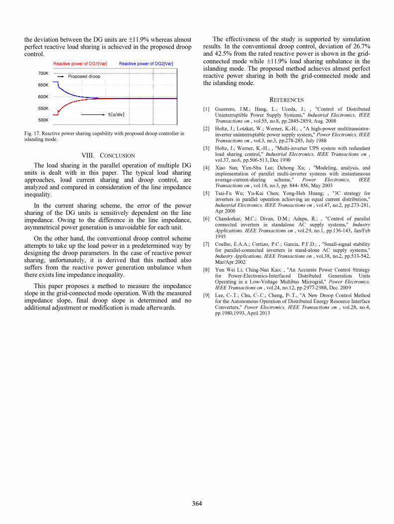
the deviation between the DO units are ±11.9% whereas almost perfect reactive load sharing is achieved in the proposed droop control.
700K
650K
600K
550K
500K
Reactive power of DG 1 [Var[ Reactive power of DG2[Var]
r-+-------J-------+-------+-------�--------I Propo�ed droop I i i
r- i i i i -- ----------------l----------------r----------------l-------·--------T--------·-------
......... I I : : ............ ! i ! i
r-�-------+-------�--------�--------r- ! ' 5[s/div] ! ! -i---------j---- ----t-------i---------i-
Fig. 17. Reactive power sharing capability with proposed droop controller in islanding mode.
VIII. CONCLUSION
The load sharing in the parallel operation of multiple DO units is dealt with in this paper. The typical load sharing approaches, load current sharing and droop control, are analyzed and compared in consideration of the line impedance inequality.
In the current sharing scheme, the error of the power sharing of the DO units is sensitively dependent on the line impedance. Owing to the difference in the line impedance, asymmetrical power generation is unavoidable for each unit.
On the other hand, the conventional droop control scheme attempts to take up the load power in a predetermined way by designing the droop parameters. In the case of reactive power sharing, unfortunately, it is derived that this method also suffers from the reactive power generation unbalance when there exists line impedance inequality.
This paper proposes a method to measure the impedance slope in the grid-connected mode operation. With the measured impedance slope, final droop slope is determined and no additional adjustment or modification is made afterwards.
364
The effectiveness of the study is supported by simulation results. In the conventional droop control, deviation of 26.7% and 42.5% from the rated reactive power is shown in the gridconnected mode while ±11.9% load sharing unbalance in the islanding mode. The proposed method achieves almost perfect reactive power sharing in both the grid-connected mode and the islanding mode.
REFERENCES
[1] Guerrero, 1.M.; Hang, L.; Uceda, 1.; , "Control of Distributed Uninterruptible Power Supply Systems," Industrial Electronics, IEEE Transactions on , vo1.55, no.8, pp.2845-2859, Aug. 2008
[2] Holtz, 1.; Lotzkat, W.; Werner, K.-H.; , "A high-power multitransistorinverter uninterruptable power supply system," Power Electronics, IEEE Transactions on, vol.3, no.3, pp.278-285, July 1988
[3] Holtz, J.; Werner, K.-H.; , "Multi-inverter UPS system with redundant load sharing control," industrial Electronics, iEEE Transactions on , vo1.37, no.6, pp.506-513, Dec 1990
[4] Xiao Sun; Yim-Shu Lee; Dehong Xu; , "Modeling, analysis, and implementation of parallel multi-inverter systems with instantaneous average-current-sharing scheme," Power Electronics, IEEE Transactions on , vol. l 8, no.3, pp. 844- 856, May 2003
[5] Tsai-Fu Wu; Yu-Kai Chen; Yong-Heh Huang; , "3C strategy for inverters in parallel operation achieving an equal current distribution," industrial Electronics, iEEE Transactions on, vo1.47, no.2, pp.273-281, Apr 2000
[6] Chandorkar, M.C.; Divan, D.M.; Adapa, R.; , "Control of parallel connected inverters in standalone AC supply systems," Industry Applications, iEEE Transactions on , vo1.29, no. l , pp. 136-143, Jan/Feb 1993
[7] Coelho, E.A.A.; Cortizo, P.c.; Garcia, P.F.D.; , "Small-signal stability for parallel-connected inverters in stand-alone AC supply systems," Industry Applications, IEEE Transactions on , vol.38, no.2, pp.533-542, Mar/Apr 2002
[8] Yun Wei Li; Ching-Nan Kao; , "An Accurate Power Control Strategy for Power-Electronics-Interfaced Distributed Generation Units Operating in a Low-Voltage Multibus Microgrid," Power Electronics, IEEE Transactions on, vo1.24, no. 12, pp.2977-2988, Dec. 2009
[9] Lee, C-.T.; Chu, C-.C.; Cheng, P-.T., "A New Droop Control Method for the Autonomous Operation of Distributed Energy Resource Interface Converters," Power Electronics, IEEE Transactions on , vo1.28, noA, pp. 1980,1993, April 2013