AN ANALYSIS AND SURVEY OF MULTILEVEL INVERTERS ...
10
820 | Page AN ANALYSIS AND SURVEY OF MULTILEVEL INVERTERS TOPOLOGIES, CONTROLS, AND APPLICATIONS 1 Abhishek Gupta, 2 Ankit Singhal , 3 Shailesh Kumar Gupta 1,2 Dept. of Electrical & Electronics Engineering, KIET, GZB, (India) 3 Dept. of Electrical & Electronics Engineering, RKGIT, GZB, (India) ABSTRACT Here multilevel inverter uses a series of semiconductor power converters thus generating higher voltage. The concept of multilevel inverters is used to decrease the harmonic distortion in the output waveform without decreasing the inverter output power. We can synthesize switched waveforms with lower levels of harmonic distortion than an equivalently rated two-level converter. Multilevel inverters can generate power with low distortion. This paper presents the most important topologies like diode-clamped inverter (neutral- point clamped),capacitor-clamped (flying capacitor), and cascaded multilevel with separate dc sources and it also presents the most relevant modulation methods developed for this family of converters: multilevel sinusoidal pulse width modulation, multilevel selective harmonic elimination, and space-vector modulation. It is believed that this article will be very much useful to the researchers for finding out the relevant references in the field of topologies and modulation strategies of multilevel inverter. Keyword: Comparison, Cascaded Multilevel Inverters, Harmonic Distortion, Multilevel Inverter, Modulation, Reduced Number Of Device Topologies, Voltage Balance. I. INTRODUCTION A power inverter is an electronic device or circuitry that changes direct current to alternating current. The input voltage, output voltage and frequency, and overall power handling depend on the design of specific device or circuitry. Inverters are used to synthesize the required AC output from DC source. However, there are many limitations regarding Thus, many types of inverter have been introduced. Generally, the most recognized type is PWM inverter. PWM inverter type offers various advantages over other types of inverters such as continuous and linear control of the output voltage as well as better harmonics elimination. Multilevel inverters include an array of power semiconductors devices and capacitor voltage sources, the output of which generate voltages with stepped waveforms. The commutation of the switches allows the addition of the capacitor voltages, which reach high voltage at the output, while the power semiconductors must withstand only reduced voltages. Fig. 1 shows a schematic diagram of one phase leg of inverters with different numbers of levels, for which the action of the power semiconductors is represented by an ideal switch with several positions.
-
Upload
khangminh22 -
Category
Documents
-
view
0 -
download
0
Transcript of AN ANALYSIS AND SURVEY OF MULTILEVEL INVERTERS ...
820 | P a g e
AN ANALYSIS AND SURVEY OF MULTILEVEL
INVERTERS TOPOLOGIES, CONTROLS, AND
APPLICATIONS
1Abhishek Gupta,
2Ankit Singhal
,
3Shailesh Kumar Gupta
1,2 Dept. of Electrical & Electronics Engineering, KIET, GZB, (India)
3Dept. of Electrical & Electronics Engineering, RKGIT, GZB, (India)
ABSTRACT
Here multilevel inverter uses a series of semiconductor power converters thus generating higher voltage. The
concept of multilevel inverters is used to decrease the harmonic distortion in the output waveform without
decreasing the inverter output power. We can synthesize switched waveforms with lower levels of harmonic
distortion than an equivalently rated two-level converter. Multilevel inverters can generate power with low
distortion. This paper presents the most important topologies like diode-clamped inverter (neutral- point
clamped),capacitor-clamped (flying capacitor), and cascaded multilevel with separate dc sources and it also
presents the most relevant modulation methods developed for this family of converters: multilevel sinusoidal
pulse width modulation, multilevel selective harmonic elimination, and space-vector modulation. It is believed
that this article will be very much useful to the researchers for finding out the relevant references in the field of
topologies and modulation strategies of multilevel inverter.
Keyword: Comparison, Cascaded Multilevel Inverters, Harmonic Distortion, Multilevel Inverter,
Modulation, Reduced Number Of Device Topologies, Voltage Balance.
I. INTRODUCTION
A power inverter is an electronic device or circuitry that changes direct current to alternating current. The input
voltage, output voltage and frequency, and overall power handling depend on the design of specific device or
circuitry. Inverters are used to synthesize the required AC output from DC source. However, there are many
limitations regarding Thus, many types of inverter have been introduced. Generally, the most recognized type is
PWM inverter.
PWM inverter type offers various advantages over other types of inverters such as continuous and linear control
of the output voltage as well as better harmonics elimination. Multilevel inverters include an array of power
semiconductors devices and capacitor voltage sources, the output of which generate voltages with stepped
waveforms. The commutation of the switches allows the addition of the capacitor voltages, which reach high
voltage at the output, while the power semiconductors must withstand only reduced voltages. Fig. 1 shows a
schematic diagram of one phase leg of inverters with different numbers of levels, for which the action of the
power semiconductors is represented by an ideal switch with several positions.

821 | P a g e
Fig.1. An Inverter with Two Levels, Three Levels And Multi Levels With One Phase
A two-level inverter generates an output voltage with two values (levels) with respect to the negative terminal of
the capacitor [see Fig. 1.], while the three-level inverter generates three voltages, and so on.
Multilevel voltage source inverter is an important alternative to the normal two level voltage source inverter
especially in high voltage application. Using multilevel technique, the amplitude of the voltage is increased,
stress in the switching devices is reduced and the overall harmonics profile is improved. Among the topologies,
the most popular one is cascaded multilevel inverter. It exhibits several features such as simple circuit layout,
less component count and avoid unbalance capacitor voltage problem. However as the number of output level
increases, the circuit becomes bulky due to the increase in the number of power devices. In this paper, it is
proposed to employ a new technique to obtain a multilevel output using less number of power semiconductor
switches when compared to ordinary cascaded multilevel inverter, which is suitable for renewable energy source
interfacing. For higher-level operation, cascaded H-Bridge multilevel inverter are preferred but major
disadvantage is requirement of multiple dc-sources, which is not feasible in many applications Voltage source
converters are also required for various industrial applications, smart grid technologies etc. Due to high power
requirement in these applications, using one power semiconductor switch directly is not advisable. For high
power and medium voltage applications multilevel converters are introduced [2]. Using multilevel converters
renewable energy sources can be easily interfaced to the grid. Using several low voltage DC sources such as
capacitors, batteries and renewable sources with series power semiconductor switches high power converter can
be achieved. These converters have several advantages over two level converters and can generate the output
voltages with low distortion and less dv/dt stresses.
II. INVERTER TOPOLOGIES
The features of multilevel inverters are following:
1. These inverters can generate output voltages with extremely low distortion.
2. These inverters draw input current with very low distortion.
3. Using sophisticated modulation methods, CM voltages can be eliminated.
4. Multilevel inverters can operate with a lower switching frequency.
A. Diode-Clamped Inverter
As the name suggests, and unlike cascaded H-bridge inverters, they need clamping devices in which the diode is
used as the clamping device to clamp the dc bus voltage so as to achieve steps in the output voltage. Thus, the
main concept of this inverter is to use diodes to limit the power devices voltage stress. An p level inverter needs

822 | P a g e
(p-1) voltage sources, 2(p-1) switching devices and (p-1) (p-2) diodes. By increasing the number of voltage
levels the quality of the output voltage is improved and the voltage waveform becomes closer to sinusoidal
waveform. Figure.4 shows a three-level diode-clamped converter in which the dc bus consists of two capacitors,
C1, C2. For dc-bus voltage V, the voltage across each capacitor is V/2 and each device voltage stress will be
limited to one capacitor voltage level V/2 through clamping diodes. To explain how the staircase voltage is
synthesized, the neutral point n is considered as the output phase voltage reference point. There are three switch
combinations to synthesize three-level voltages across a and n.
1. Van= V/2, turn on the switches S1andS2.
2. Van= 0, turn on the switches S2 and S1′.
3. Voltage level Van= - V/2 turn on the switches S1′, S2′.
A five-level diode-clamped converter in which the dc bus consists of four capacitors, C1, C2, C3, and C4. For
dc-bus voltage V, the voltage across each capacitor is V/4 and each device voltage stress will be limited to one
capacitor voltage level V/4 through clamping diodes.
Fig.2: Diode-Clamped Multilevel (Three-Level & Five-Level) Inverter Circuit Topologies.
To synthesize 5-level output phase voltage, switching sequence as given in table 1. State condition 1 means
switch ON and 0 means switch OFF.
Table1: Switching states in one leg of the five level diode clamped inverter level

823 | P a g e
B. Cascaded Multilevel Inverter
One of the basic and well known topologies among all multilevel inverters is cascaded H-bridge multilevel
inverters. It can be used for both single and three phase conversion. The concept of this inverter is based on
connecting H-bridge inverters in series to get a sinusoidal voltage output. The output voltage is the sum of the
voltage that is generated by each cell. The switching angles can be chosen in such a way that the total harmonic
distortion is minimized. One of the advantages of this type of multilevel inverter is that it needs less number of
components i.e. it does not need any capacitors or diodes for clamping comparative to the Diode clamped or the
flying capacitor, so the price and the weight of the inverter is less than that of the two types.Figure.3 shows the
power circuit for one phase leg of a three-level and five-level cascaded inverter. In a 3-level cascaded inverter
each single-phase full-bridge inverter generates three voltages at the output: +Vd, 0, -Vd (zero, positive dc
voltage, and negative dc voltage). This is made possible by connecting the capacitors. The resulting output ac
voltage swings from –Vd to +Vd with three levels, -2Vd to +2Vd.
Fig.3: Single Phase Structures of Cascaded Inverter (A) 3-Level, (B) 5-Level
III. CAPACITOR CLAMPED INVERTER
A quite well known topology of multilevel inverter is capacitor clamped inverter. This type of multilevel
inverter requires capacitor to be pre-charged. Capacitor clamped switching cells are connected in series. This
topology has a ladder structure of dc side capacitors, where the voltage on each capacitor differs from that of the
next capacitor. The voltage increment between two adjacent capacitor legs gives the size of the voltage steps in
the output waveform.fig shows single phase n-level configuration of capacitor clamped inverter. A p-level
inverter will require a total of (p-1) × (p-2)/2 clamping capacitors per phase leg in addition to (p-1) main dc bus
capacitors. The voltage synthesis in a five-level capacitor-clamped converter has more flexibility than a diode-
clamped converter. Using Figure.2 (b) the voltage of the five-level phase-leg “a” output with respect to the
neutral point n (i.e. Van), can be synthesized by the following switch combinations.
1. Van= V/2, turn on all upper switches S1 - S4.
2. Van= V/4, there are three combinations.
3. Turn on switches S1, S2, S3 and S1′. (Van= V/2 of upper C4‟s - V/4 of C1‟s).
4. Turn on switches S2, S3, S4 and S4′.(Van= 3V/4 of upper C3‟s - V/2 of C4‟s).
5. Turn on switches S1, S3, S4 and S3′. (Van= V/2 of upper C4‟s - 3V/4 or C3‟s + V/2 of upper C„).
6. Van= 0, turn on upper switches S3, S4, and lower switch S1′, S2′.

824 | P a g e
7. Van= -V/4, turn on upper switch S1 and lower switches S1′, S2′and S3′.
8. Van= -V/2, turn on all lower switches S1′, S2′, S3′ and S4′.
Fig.4: Capacitor-Clamped Multilevel Inverter Circuit Topologies, (A) 3-Level Inverter (B) 5-
Level Inverter.
IV. MULTILEVEL SINUSOIDAL PWM
Multilevel inverters generate stepped AC and use many number of switches and generate staircase type output
through controlled switching. It is a popular control method widely used in inverter circuit. This method is easy
to implement. The modulating signal is a sinusoid of frequency fm and amplitude Am. At every instant, each
carrier is compared with the modulating signal. Each comparison switches the switch "on" if the modulating
signal is greater than the triangular carrier assigned to that switch.
Figure.6: Inverter Cell Voltages. (A) Output Voltage and Reference with SPWM. (B) Output
Voltage and Reference with Injection of Sinusoidal Third Harmonic.
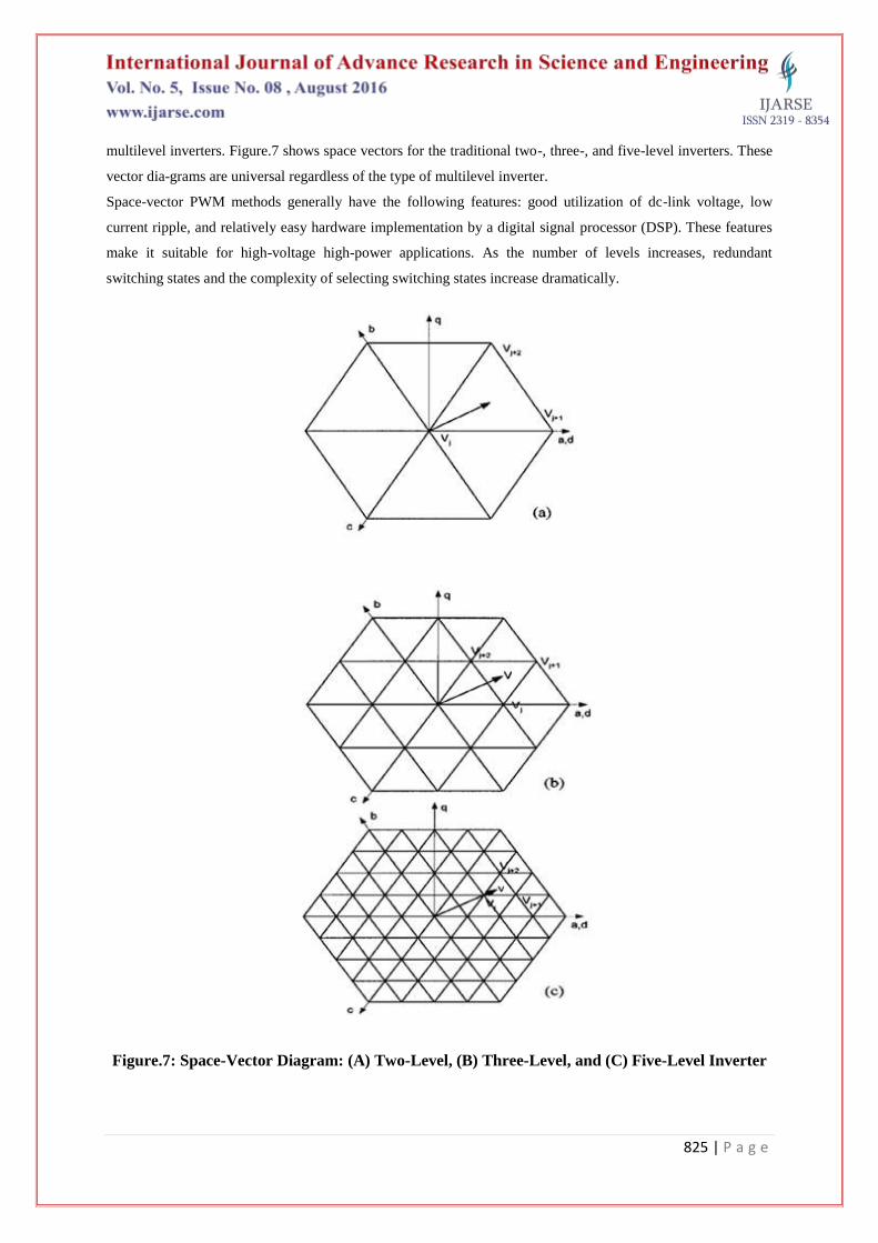
V. SPACE VECTOR MODULATION
Space vector modulation is an algorithm for control of pulse width modulation. It is used for creating of
alternating current waveforms most commonly to drive 3-phase ac powered motors at varying speeds. One
active area of development is in the reduction of total harmonic distortion created by rapid switching inherent to
these algorithms. The basic idea of voltage space vector modulation is to control the inverter output voltages so
that their Parks representation will be approximately equals the reference voltage vector. In the case of two level
inverter, the output of each phase will be either +V/2 or – V/2.The SVM technique can be easily extended to all
825 | P a g e
multilevel inverters. Figure.7 shows space vectors for the traditional two-, three-, and five-level inverters. These
vector dia-grams are universal regardless of the type of multilevel inverter.
Space-vector PWM methods generally have the following features: good utilization of dc-link voltage, low
current ripple, and relatively easy hardware implementation by a digital signal processor (DSP). These features
make it suitable for high-voltage high-power applications. As the number of levels increases, redundant
switching states and the complexity of selecting switching states increase dramatically.
Figure.7: Space-Vector Diagram: (A) Two-Level, (B) Three-Level, and (C) Five-Level Inverter
826 | P a g e
VI. A LITERATURES SURVEY WITH MULTI LEVEL INVERTER TOPOLOGIES AND
CONTROL TECHNIQUE
DIODE CLAMPED INVERTER
CASCADED MULTILEVEL INVERTER
FLYING CAPACITOR MULTILEVEL INVERTER
SINUSOIDAL PWM
SPACE VECTOR PWM
SHE-PWM
SPACE VECTOR CONTROL
Diode Clamped Inverter
The main concept of this inverter is to use diodes to limit the power devices voltage stress. A complete analysis
of the voltage balance theory for a five-level back to- back system is given. This control strategy regulates the
dc bus voltage, balances the capacitors, and decreases the harmonic components of the voltage and current.
Robert Stala, et al. [3], introduced a new operational mode for diode-clamped multilevel inverters termed quasi
two-level operation is proposed. Such operation avoid the imbalance problem of the dc-link capacitors for
multilevel inverters with more than three levels.
Cascaded Multilevel Inverter
An arm-balancing control to achieve voltage balancing under all the operating condition is proposed. Farid
Khoucha , et al. [4], suggested the impacts of the connected load to the cascaded H-bridge converter as well as
the switching angles on the voltage regulation of the capacitors are studied. This literature proves that voltage
regulation is only attainable in a much limited operating conditions that it was originally reported.
Flying Capacitor Multilevel Inverter
Suroso, et al.,[14], presented in this literature two active capacitor voltage balancing schemes are proposed for
single-phase (Hbridge) flying-capacitor multilevel converters. They are based on the circuit equations of flying
capacitor converters. These methods are shown to be effective on capacitor voltage regulation in flying-
capacitor multilevel converters. The development of multilevel hysteresis current regulation strategies.
Sinusoidal Pwm
Wahidah Abd. Halim, et al.,[12], used an original multicarrier sub harmonic pulsewidth modulation (PWM),
called disposition band carrier and phase-shifted carrier PWM (DBC-PSC-PWM), method is developed to
produce (n ×m + 1) output voltage levels and to improve the output voltage harmonic spectrum with a wide
output frequency range. T. Noguchi , et al., presented in this literature a carrier-based closed-loop control
technique has been developed to reduce the switching losses based on insertion of „no switching‟ zone within
each half cycle of fundamental wave. Suroso, et al., suggested a five-level pulse width modulation inverter
configuration, including chopper circuits as DC current-power source circuits using small smoothing inductors,
is verified through computer simulations and experimental tests.

827 | P a g e
Space Vector Pwm
A new technique is proposed in this literature, by which these two-level vectors are translated to the switching
vectors of the multilevel inverter by adding the center of the subhexagon to the two-level vectors. J. Selvaraj, et
al. [8], presented in this literature an approach to reduce common-mode voltage (CMV) at the output of
multilevel inverter using 3-D space-vector modulation (SVM). N. A. Rahim, et al. [8], addressed a new
multilevel SVPWM technique with a five-segment switching sequence, where half-wave symmetrical PWM
voltage waveforms are used to balance the inductor common-mode dc voltages.
She-PWM
Ilhami Colak, et al., focused on a new formulation of selective harmonic elimination pulse width modulation
(SHE-PWM) technique suitable for cascaded multilevel inverters with optimized DC voltage levels. Jorge Pontt,
et al., introduced a neutral point voltage control strategy for the three-level active neutral point clamped (ANPC)
converter using selective harmonic elimination pulse width modulation (SHE-PWM). Jorge Pontt , et al.,
presented in this literature a control strategy is proposed to regulate the voltage across the FCs at their respective
reference voltage levels by swapping the switching patterns of the switches based on the polarity of the output
current.
Space Vector Control
José Rodríguez, et al., addressed a switching strategy for multilevel cascade inverters, based on the space-vector
theory. The proposed switching strategy generates a voltage vector with very low harmonic distortion and
reduced switching frequency. J. S. Lai , et al. [1], used a new PWM technique for induction motor drives
involving six concentric dodecagonal space vector structures is proposed. José Rodríguez, et al., introduced a
switching strategy for multilevel cascade inverters, based on the space-vector theory.
VII. CONCLUSION
The following tables give conclusion of the paper as:
a) Multilevel Inverter Topologies Point of View
Parameters
Total No.
of
Literatures
Reviews
(44)
% of
Literatures
(44)
Diode
clamped
12 28.27
Cascaded H
-bridge
18 39.09
Flying
Capacitor
14 32.70

828 | P a g e
The Conclusion 28.27 % of total literatures are reviews based on Diode Clamped Multilevel Inverter, 39.09 %
of total literatures are reviews based on Cascaded H-bridge Multilevel Inverter, 32.70 % of total literatures are
reviews based on Flying Capacitor Multilevel Inverter viewpoints.
7.1 Modulation Strategies Point of View
From below tables 3, it is concluded that the 26.32 % of total literatures are reviews based on Sinusoidal PWM
Technique, 28.95 % of total literatures are reviews based on Space Vector PWM Technique, 34.21% of total
literatures are reviews based on Selective Harmonic Elimination PWM Technique and 10.52 % of total
literatures are reviews based on Space Vector Control Technique viewpoints.
Parameters
Total No. of
Literatures
Reviews (44)
% of
Literatures
(44)
SPWM 10 26.99
SVM 11 29.09
SHE-PWM 13 35.71
SVC 4 11.20
Table: 3 Modulation Strategies Point of View
From above tables 3, it is concluded that the 26.99% of total literatures are reviews based on Sinusoidal PWM
Technique, 29.09 % of total literatures are reviews based on Space Vector PWM Technique, 35.71% of total
literatures are reviews based on Selective Harmonic Elimination PWM Technique and 11.20 % of total
literatures are reviews based on Space Vector Control Technique viewpoints.
This paper cannot cover or reference all the related work, but the fundamental principle of different multilevel
inverters has been introduced systematically. This survey article will be very much useful to the researchers for
finding out the relevant references as well as the previous work done in the field of multilevel inverter
topologies and their modulation technique.
REFERENCES
[1] J. Rodriguez, J. S. Lai and F. Z. Peng, -Multilevel Inverters: Survey of Topologies, Controls, and
Applications,‖ IEEE Transactions on Industry Applications, vol. 49, no. 4, Aug. 2002, pp. 724-738.
[2] Baoming Ge, Fang Zheng Peng, Aníbal T. de Almeida, and Haitham Abu-Rub, ―An Effective Control
Technique for Medium-Voltage High-Power Induction Motor Fed by Cascaded Neutral-Point- Clamped
Inverter‖, IEEE Trans On Industrial Electronics, Vol. 57, No. 8, pp. 2659-2668, Aug 2010.
[3] Robert Stala, ―Application of Balancing Circuit for DC-Link Voltages Balance in a Single-Phase Diode-
Clamped Inverter With Two Three-Level Legs‖, IEEE Trans On Industrial Electronics, Vol. 58, No. 9, pp.
4185-4195, Sept 2011.
829 | P a g e
[4] Farid Khoucha, Soumia Mouna Lagoun, Khoudir Marouani, Abdelaziz Kheloui, and Mohamed El Hachemi
Benbouzid, ―Hybrid Cascaded H-Bridge Multilevel-Inverter Induction-Motor-Drive Direct Torque
Control for Automotive Applications‖, IEEE Trans. On Industrial Electronics, Vol. 57, No. 3, pp. 892-899,
March 2010.
[5] Huiying Zheng; Shuhui Li ; Chuanzhi Zang ; Weijian Zheng- Coordinated control for grid integration of PV
array, battery storage and super capacitor‖ IEEE Trans. On Power and Energy Society General Meeting
(PES), Publication Year: 2013 , Page(s): 1 – 5, 2013.
[6] Morya, A.K. ; Shukla, A.,"Space vector modulated cascaded H-bridge multilevel converter for grid
integration of large scale photovoltaic power plants ―, Fourth International Conference on Power
Engineering, Energy and Electrical Drives (POWERENG), 2013, Publication Year: 2013 , Page(s): 181 –
186.
[7] Biju, K.; Ramchand, R., ―Modeling and simulation of single phase five level inverter fed from renewable
energy sources‖ Annual International Conference on Emerging Research Areas, 2013 and International
Conference on Microelectronics, Communications and Renewable Energy (AICERA/ICMiCR),
2013,Publication Year: 2013 , Page(s): 1 – 5
[8] N. A. Rahim and J. Selvaraj, ―Multistring five-level inverter with novel PWM control scheme for PV
application,‖ IEEE Trans. Ind. Electron., vol. 57, no. 6, pp. 2111–2123, Jun. 2010.
[9] C. H. Ng, M. A. Parker, L. Ran, P. J. Tavner, J. R. Bumby, and E. Spooner, ―A multilevel modular
converter for a large, light weight wind turbine generator,‖ IEEE Trans. Power Electron., vol. 23, no. 3, pp.
1062–1074, May 2008.
[10] Guohui Yuan, ―Improving grid realiabilty through integration of distributed PV and energy storage‖, IEEE
PES Innovative Smart Grid Technologies (ISGT), 2012,Publication Year: 2012 , Page(s): 1 – 2.
[11] José Rodríguez, Luis Morán, Jorge Pontt, Pablo Correa, and Cesar Silva, ―A High-Performance Vector
Control of an 11-Level Inverter‖, IEEE Trans. On Industrial Electronics, Vol. 50, No. 1, pp. 80-
85,Feb.2003.
[12] Wahidah Abd. Halim and Nasrudin Abd. Rahim, ―FPGA-Based Pulse-Width Modulation Control For
Single-Phase Multilevel Inverter‖, IEEE First Conference on Clean Energy and Technology, CET, pp.57-
62, 201
[13] Ilhami Colak, Ramazan Bayindir, Ersan Kabalci, ―Design and Analysis of a 7-Level Cascaded Multilevel
Inverter with Dual SDCSs‖, International Symposium on Power Electronics, Electrical Drives, Automation
and Motion, pp.180-185, 2010.
[14] Suroso, and T. Noguchi, ―Common-emitter topology of multilevel current-source pulse width modulation
inverter with chopper-based DC current sources‖, IET Power Electronics, Vol. 4, Iss. 7, pp. 759–766, 2010.