
Automationsystems Drive solutions Controls Inverters Motors ...
136
Automation systems Drive solutions Controls Inverters Motors Gearboxes Engineering Tools Inverters: Inverter Drives 8400 motec Motors: MD three-phase AC motors L-force catalogue
-
Upload
khangminh22 -
Category
Documents
-
view
0 -
download
0
Transcript of Automationsystems Drive solutions Controls Inverters Motors ...

Automation systemsDrive solutions
ControlsInvertersMotorsGearboxesEngineering Tools
Inverters: Inverter Drives 8400 motec
Motors:MD three-phase AC motors
L-force catalogue


Lenze makes many things easy for you.About Lenze
Amatter of principle: the right products for every application.
L-force product portfolio
1.1Controller-based AutomationAutomation systems
1.2Drive-based automation
2.1HighLine tasksDrive solutions
2.2StateLine tasks
2.3BaseLine tasks
3.1Controller 3200 CCabinet ControllerControls
3.2Controller c300
3.3Controller p500Panel Controller
3.4Controller p300
3.5I/O system 1000'
3.6Monitor Panel
4.1Inverter Drives 8400 protecDecentralisedInverters
4.2Inverter Drives 8400 motec
4.4Servo Drives 9400 HighLineCabinet
4.5Inverter Drives 8400 TopLine
4.6Servo Inverters i700
4.7Inverter Drives 8400 HighLine
4.8Inverter Drives 8400 StateLine
4.10Inverter Drives 8400 BaseLine
5.1MCS synchronous servo motorsServo motorsMotors
5.2MD☐KS synchronous servo motors
5.3MQA asynchronous servo motors
5.4MCA asynchronous servo motors
5.5MF three-phase AC motorsThree-phase AC motors
5.6MH three-phase AC motors
5.7MD three-phase AC motors
5.8m300 Lenze Smart Motor
5.9MD/MH basic three-phase AC motors
6.1g700-P planetary gearboxAxial gearboxGearboxes
6.2MPR/MPG planetary gearboxes
6.3g500-H helical gearbox
6.4GST helical gearboxes
6.5g500-S shaft-mounted helical gearbox
6.6GFL shaft-mounted helical gearboxes
6.7g500-B bevel gearboxRight-angle gearbox
6.8GKR bevel gearboxes
6.9GKS helical-bevel gearboxes
6.10GSS helical-worm gearboxes
6.11Assignment see aboveMotor data
7.1NavigatorEngineering Tools
7.2Drive Solution Designer
7.3Drive Solution Catalogue
7.4Engineer
7.5PLC Designer
7.6VisiWinNET®
7.7EASY Starter
Selected portfolio
Additional portfolio
Contents of the L-force catalogue

Lenze makes manythings easy for you.Withourmotivated and committed approach,weworktogether with you to create the best possible solutionand set your ideas inmotion - whether you are lookingto optimise an existingmachine or develop a new one.We always strive to make things easy and seek perfec-tion therein. This is anchored in our thinking, in ourservices and in every detail of our products. It's as easyas that!
321
Implementing solutionsDrafting conceptsDeveloping ideas
Our easy formula for satisfied customers isto establish an active partnership with fast
We seewelcome challenges in yourmachinetasks, supporting youwith our comprehens-
Are you looking to build the best machinepossible and alreadyhave some initial ideas?
decision-making processes and an individu-ive expertise andproviding valuable impetusThenget thesedownonpaper togetherwithally tailored offer. We have been using thisfor your innovations. We take a holistic viewus, startingwith small innovative details andsimple principle to meet the ever more spe-of the individual motion and control func-stretching all the way to completely newcialised customer requirements in the fieldof mechanical engineering for many years.
tions here and draw up consistent, end-to-end drive and automation solutions for you
machines.Working together,wewill developan intelligent and sustainable concept that
- keeping everything as easy as possible andas extensive as necessary.
is perfectly alignedwith your specific require-ments.
54
Ensuring productivityManufacturing machines
Productivity, reliability andnewperformancepeaks on a daily basis – these are our key
Functional diversity in perfect harmony: asone of the few full-range providers in the
success factors for yourmachine. After deliv-market, we can provide you with preciselyery, we offer you cleverly devised servicethoseproducts that youactually need for anyconcepts to ensure continued safe operation.machine task – no more and no less. Our L-The primary focus here is on technical sup-force product portfolio, a consistent platformport, based on the excellent application ex-for implementing drive and automation
tasks, is invaluable in this regard. pertise of our highly-skilled and knowledge-able after-sales team.

Amatter of prin-ciple:the right productsfor every application.
Lenze's extensive L-force product portfolio follows avery simple principle. The functions of our finely scaledproducts areassigned to the three linesBase-Line, State-Line or High-Line.
But what does this mean for you? It allows you toquickly recognise which products represent the bestsolution for your own specific requirements.
Powerful products with a major impact:• Easy handling• High quality and durability• Reliable technologies in tunewith the latest develop-ments
Lenze products undergo the most stringent testing inour own laboratory. This allows us to ensure that youwill receive consistently high quality and a long servicelife. In addition to this, five logistics centres ensure thatthe Lenze products you select are available for quickdelivery anywhere across the globe. It's as easy as that!

Controls
Engineering Tools
L-force product portfolio

Inverters
L-force product portfolio

Motors
L-force product portfolio

Gearboxes
L-force product portfolio


Inverter Drives 8400motec0.37 to 7.5 kW
Inverters


4.2 - 4Product keyGeneral information
4.2 - 5Equipment
4.2 - 6List of abbreviations
4.2 - 78400 motec
4.2 - 8Functions and features
4.2 - 9Operating modes
4.2 - 11Standards and operating conditionsTechnical data
4.2 - 12Rated data 400 V
4.2 - 22The three units
4.2 - 23Drive Unit
4.2 - 24Communication Unit
4.2 - 24Wiring Unit
4.2 - 26Mains connection
4.2 - 26Motor connection
4.2 - 27Connection diagrams
4.2 - 28Control connections
4.2 - 31Memory moduleModules
4.2 - 31Safety system (STO)
4.2 - 32Communication modules
4.2 - 33Communication modules without fieldbus link
4.2 - 34Communication module: AS-Interface (AS-i)
4.2 - 36Communication module: CANopen
4.2 - 38EtherCAT® communication module
4.2 - 40EtherNet/IP communication module
4.2 - 42PROFIBUS communication module
4.2 - 44PROFINET communication module
4.2 - 47Wiring Unit versionsAccessories
4.2 - 47Connector modules
4.2 - 49Internal brake resistor
4.2 - 49Wall mounting
4.2 - 50Brake resistors
4.2 - 51USB diagnostic adapter
4.2 - 52Diagnosis terminal
4.2 - 52Switch/potentiometer unit
4.2 - 53System cables
Inverter Drives 8400 motecContents
4.2

Product key
V01-en_GB-12/20134.2 - 4
Inverter Drives 8400 motecGeneral information
4.2

Equipment
DIP switch for quick setting
Safety system (STO)
Optional in the communication module
Status display LED
L-force diagnostic interface
for USB adapter when PC or keypad is connected
Communicationmodule
rotary so terminal side is variable
Plug connection
The three parts of the motec can be plugged into one another
Plug connections
8 slotsA1 - A4 and B1 - B4
Power connections
Prepared for PGScrewed connection or plug-in module
4.2 - 5V01-en_GB-12/2013
Inverter Drives 8400 motecGeneral information
4.2

List of abbreviations
Asynchronous motorASMDimensions[mm]bSlot for diagnostic adapterDIAGThermal capacity[KWs]CthDeutsches Institut für Normung e.V.DINRated switching frequency[kHz]fchEuropean standardENDimensions[mm]hDegrees of protection provided by enclosures (IPcode)
EN 60529Rated output current[A]IN, outRated mains current[A]IN, AC
Classification of environmental conditions; Part 3:Classes of environmental parameters and theirlimit values
EN 60721-3Mass[kg]mMax. speed[r/min]nmaxTypical motor power[kW]P
Electrical variable speeddrives Part 3: EMC require-ments including special test methods
EN 61800-3Power loss[kW]PVRated power[kW]PN International Electrotechnical CommissionIECRated resistance[Ω]RN Functional safety of electrical/electronic/program-
mable electronic safety-related systemsIEC 61508
Dimensions[mm]tMains voltage[V]UAC International Mounting CodeIMDC supply[V]UDC International Protection CodeIPRated voltage[V]UN, AC Slot for communicationmodule (module commu-
nication interface)MCI
Max. output voltage[V]Uout
National Electrical Manufacturers AssociationNEMAUnderwriters Laboratory Listed ProductULUnderwriters Laboratory Recognized ProductURVerband deutscher Elektrotechniker (Associationof German Electrical Engineers)
VDE
V01-en_GB-12/20134.2 - 6
Inverter Drives 8400 motecGeneral information
4.2

8400 motec
Further advantagesThe Inverter Drives 8400 motec excel through the greatest possibleuser-friendliness during operation and installation. • 200% overload current (3s)
• V/f control with and without encoderParticularly when used for "basic applications", the Inverter Drives8400 motec is able to demonstrate its exemplary efficiency with re-gard to costs, space, time and energy
• Sensorless vector control• Short-circuit and earth-fault protected• DC-injection braking• S-shaped ramp for smooth acceleration
Cost advantages • Max. output frequency 500 Hz• The easiest commissioning processes via DIP switch and poten-tiometer settings
• 3 fixed frequencies• CANopen, PROFIBUS, PROFINET, EtherCAT®, EtherNet/IP and ASinterface• Reducedenergy requirements thanks to energy-saving functional-
ities in combination with the geared motors from Lenze • STO safety function
Space savings Sympathetically easy• Integrated safetyand fieldbus communication tailored to individualrequirements
• The large LED display, which can still be read from great distances,displays the status during operation and uses various flashing se-quences to provide information on error causes. This keeps dia-gnostics easy to understand
• Modular structure minimises your spare parts inventory
Time savingsMechanically and electrically robust• Reduction in assembly and installation times through pluggable
connection system: "Unpack – plug in and use!" • Thanks to the high degree of protection (IP65), ideally suited foruse in the harshest environments.• Easy replacement of the memory module simplifies standard set-
up and increases availabilityA win for decentralised applications
Energy efficiency • The 8400 motec meets all requirements of a modern, universallydeployable and cost-efficient motor inverter. This makes it ideally• The "VFC eco" mode offers intelligent adjustment of the magnet-
ising current suited for decentralised duties in the field of intralogistics, such asat airports or distribution centres.• Energy savings of up to 30% in partial load operation
Inverter Drives 8400 motec
4.2 - 7V01-en_GB-12/2013
Inverter Drives 8400 motecGeneral information
4.2

Functions and features
Mode
8400 motecConrol types, motor control
For three-phase asynchronous motorsSensorless vector control (SLVC)
For three-phase AC motors and asynchronous servo motor (linear or square-law)V/f control (VFCplus)
For three-phase asynchronous motorsEnergy saving function (VFC eco)Basic functions
Freely assignable user menuParameter change-overDC brake functionFlying restart circuitS-shaped ramps for smooth accelerationPID controller3 fixed frequenciesMasking frequencies
Technology applications
Speed actuating driveSwitch-off positioning without feedback
Monitoring and protective measures
Short circuitEarth faultOvervoltageMotor phase failureOvercurrentI² x t-Motor monitoringMotor overtemperatureMains phase failureProtection for cyclical mains switchingMotor stalling
Diagnostics
Data logger, logbook
1 LEDsStatus display
IntegratedDiagnostic interfaceFor USB diagnostic adapter or keypad (diagnosis terminal)
Braking operation
IntegratedBrake chopper
Built-on module or externalBrake resistor
V01-en_GB-12/20134.2 - 8
Inverter Drives 8400 motecGeneral information
4.2

Operating modes
An inverter enables energy-efficient operation of a system in virtuallyall application cases. The various operating modes, which can becreated by making just a few simple settings, facilitate this. The fol-lowing characteristics and corresponding specifications listed on thefollowing pages can be used to calculate the optimum operatingmode during the project planning phase.
Standard setting
In its initial statewhen delivered, the inverter is set up for basic oper-ation with a three-phase AC motor with V/f control. When operated
V/f at 50 Hz
in this mode, the rated torque of the motor is available in a settingrange up to 50 Hz.
Extended setting range up to 87 Hz
If the V/f switchover point on the inverter is set to 87 Hz, the ratedtorque can be used across an extended setting range. Here, a
V/f at 87 Hz
230/400Vmotor is for example used and operated in a delta layoutwith a 400V inverter. The setting range is then increased by 40 %.The invertermust be dimensioned for a ratedmotor current of 230 V.
Operation with inverter-optimised MF motors
Large setting ranges and optimum operation at the rated torque:these are the strengths of the MFmotor when used in combination
V/f at 120 Hz
with an inverter. The motors are optimised for a setting range up to120 Hz. Compared to conventional 50Hz operation, the setting rangeincreases by 250 %. It is quite simply not possible for a drive to beoperated any more efficiently in a machine.
Operation with low loads
This operatingmode canbeused for various applications, e.g. for fansand pumps:
Square-law characteristic
In fan and pump applications, the load behaviour follows a square-lawcharacteristic dependingon the speed.Often, anoverloadcapacityof 120% is sufficient. This serves to operate the inverter during oper-ation with increased power, i.e. the inverter can be dimensioned onepower size smaller. The square-law characteristic which correspondsto the load behaviour can be set in the inverter.
4.2 - 9V01-en_GB-12/2013
Inverter Drives 8400 motecGeneral information
4.2

Operating modes
VFC-eco energy saving mode
The InverterDrives 8400make energy saving especially easywith the"VFC eco" function. Particularly in the partial load operational range,
VFC-eco energy saving mode
this function significantly reduces energy requirements. Combinedwith the new L-force MF three-phase AC motors, this drive solutionimpresseswith themaximumenergy efficiency of a LenzeBlueGreensolution.
The "VFCeco"modeadjusts themagnetising current of amotor intel-ligently to actual requirements. This is particularly useful in partialload operational range, as this is precisely where three-phase ACmotors need to be supplied with a greater magnetising current thanthe operating conditions actually require. The "VFC eco"mode allowslosses to be reduced so much that savings of up to 30% can beachieved.
Energy efficiency can then be increased even further with the MFthree-phaseACmotors. Thesemotors havebeen specifically designedfor operationwith frequency inverters. Theyoperate at 120Hz insteadof 50 Hz, as 4-pole three-phase ACmotors are at their most efficientat this frequency.
Overcurrent operation
The inverters can be driven at higher amperages beyond the ratedcurrent if the duration of this overcurrent operation is time limited.
Overcurrent operation
Two utilisation cycles with a duration of 15 s and 180 s are defined.Within these utilisation cycles, an overcurrent is possible for a certaintime if afterwards an accordingly long recovery phase takes place.For bothutilisation cycles, amoving average is determined separately.The adjacent diagramshowsboth cycles: 15 s in red and180 s in blue.The overload times tol are 3 s (T1) and 60 s (T3) respectively, the cor-responding recovery times tre are 12 s (T2) and 120 s (T4) respectively.The following tables show the resulting maximum output currents.Monitoring of the device utilisation (I x t) activates the set error re-sponse (trip or warning if one of the two utilisation values exceedsthe limit of 100 %.
Switching frequencies
Onan inverter, the term "switching frequency" is understood tomeanthe frequencywithwhich the input andoutputs of theoutputmodule(inverter) are switched. On an inverter, the switching frequency cangenerally be set to values between 2 and 16 kHz, whereby the selec-tion is based on the respective power output.Since losses (in the form of heat) can be generated when switchingthe modules, the inverter can provide a higher output current at aswitching frequency of 2 kHz. In addition to this, it is also importantto differentiate between operation at a fixed switching frequencyanda variable switching frequency,whereby the switching frequencyis automatically reduced based on the output current here.The data for operation at increased output is permitted for operationat a switching frequency of 2 or 4 kHzand in anambient temperatureof max. 40 0 C.
V01-en_GB-12/20134.2 - 10
Inverter Drives 8400 motecGeneral information
4.2

Standards and operating conditions
Mode
8400 motecProductConformity
Low-Voltage DirectiveCE
2006/95/EGApproval
Power Conversion Equipment (File-No. E170350)UL 508C
CSA 22.2 No. 14CSACertification
GOST-RDegree of protection
IP65 1)EN 60529
Type 4NEMA 250Climatic conditions
1K3 (temperature: -30 °C ... +60 °C)Storage (EN 60721-3-1)
2K3 (temperature: -30 °C ... +75 °C)Transport (EN 60721-3-2)
3K3 (temperature: -30°C ... +55°C)Operation (EN 60721-3-3)
2.5% / KCurrent derating at over 45°CSite altitude
4000[m]HmaxAmsl
5[%/1000 m]Current derating at over 1000 mVibration resistance
2M2Transport (EN 60721-3-2)
3M6Operation (EN 60721-3-3)
General conditions: acceleration resistant up to 2 gOperation (Germanischer Lloyd)
Mode
8400 motecProductSupply form
Systems with earthed star point (TN and TT systems)Systems with high-resistance or isolated star point (IT systems)
Noise emission
Integrated radio interference suppressionmeasures: conducted, cat-egory C1 2)
EN 61800-3
Wall mounting: category C2 with a shielded motor cable of up to 20m
Insulation resistance
≤ 2000 m amsl overvoltage category IIIEN 61800-5-1> 2000 m amsl overvoltage category II
Degree of pollution
2EN 61800-5-1Protective insulation of control circuits
Safe mains isolation: double/reinforced insulationEN 61800-5-1
Not with plug-in or braking resistor modules.1)
Category C2 above 4.0 kW.2)
4.2 - 11V01-en_GB-12/2013
Inverter Drives 8400 motecTechnical data
4.2

Rated data 400 V
• The data is valid for operation at 400 V AC.• Unless otherwise specified, the data refers to the default setting.
Typical motor power
0.75 1)0.550.55 1)0.37[kW]P4-pole asynchronous motorProduct key
E84DVB☐5514S☐☐☐2☐E84DVB☐3714S☐☐☐2☐Inverter
E84DGDVB55142PSE84DGDVB37142PSDrive UnitMains voltage range
3/PE AC 320 V-0 % ... 528 V+0 %, 45 Hz-0 % ... 65 Hz+0 %[V]UACRated mains current
2.21.81.61.3[A]IN, ACRated output current
2.21.81.61.3[A]IN, outRated switching frequency
4848[kHz]fchOutput current
2.21.81.61.3[A]Iout4 kHz
1.81.3[A]Iout8 kHz
1.20.9[A]Iout16 kHz
Data for 60 s overload
Max. output current
2.72.0[A]Imax, outOverload time
60.0[s]tolRecovery time
120.0[s]tre
Data for 3 s overload
Max. short-timeoutput current
3.62.6[A]Imax, outOverload time
3.0[s]tolRecovery time
12.0[s]tre
Increased rated power operating mode at 40 °C ambient temperature andmax. mains voltage of 400 V AC
1)
V01-en_GB-12/20134.2 - 12
Inverter Drives 8400 motecTechnical data
4.2

Rated data 400 V
• The data is valid for operation at 400 V AC.• Unless otherwise specified, the data refers to the default setting.
Typical motor power
0.75 1)0.550.55 1)0.37[kW]P4-pole asynchronous motorProduct key
E84DVB☐5514S☐☐☐2☐E84DVB☐3714S☐☐☐2☐Inverter
E84DGDVB55142PSE84DGDVB37142PSDrive UnitPower loss
0.0330.026[kW]PVMass
2.6[kg]mMax. cable length
20[m]lmaxShielded motor cable 2)
Brake chopper rated data
Rated power, Brake chopper
0.70.60.50.4[kW]PNMax. output power, Brakechopper
0.80.6[kW]Pmax, 1Min. brake resistance
180.0[Ω]Rmin
Dimensions
Dimensions
109[mm]hHeight
161[mm]bWidth
241[mm]tDepth
Increased rated power operating mode at 40 °C ambient temperature andmax. mains voltage of 400 V AC
1)
Technically possible cable lengths, irrespective of EMC requirements2)
4.2 - 13V01-en_GB-12/2013
Inverter Drives 8400 motecTechnical data
4.2

Rated data 400 V
• The data is valid for operation at 400 V AC.• Unless otherwise specified, the data refers to the default setting.
Typical motor power
1.50 1)1.101.10 1)0.75[kW]P4-pole asynchronous motorProduct key
E84DVB☐1124S☐☐☐2☐E84DVB☐7514S☐☐☐2☐Inverter
E84DGDVB11242PSE84DGDVB75142PSDrive UnitMains voltage range
3/PE AC 320 V-0 % ... 528 V+0 %, 45 Hz-0 % ... 65 Hz+0 %[V]UACRated mains current
3.83.22.92.4[A]IN, ACRated output current
3.83.22.92.4[A]IN, outRated switching frequency
4848[kHz]fchOutput current
3.83.22.92.4[A]Iout4 kHz
3.22.4[A]Iout8 kHz
2.11.6[A]Iout16 kHz
Data for 60 s overload
Max. output current
4.83.6[A]Imax, outOverload time
60.0[s]tolRecovery time
120.0[s]tre
Data for 3 s overload
Max. short-timeoutput current
6.44.8[A]Imax, outOverload time
3.0[s]tolRecovery time
12.0[s]tre
Increased rated power operating mode at 40 °C ambient temperature andmax. mains voltage of 400 V AC
1)
V01-en_GB-12/20134.2 - 14
Inverter Drives 8400 motecTechnical data
4.2

Rated data 400 V
• The data is valid for operation at 400 V AC.• Unless otherwise specified, the data refers to the default setting.
Typical motor power
1.50 1)1.101.10 1)0.75[kW]P4-pole asynchronous motorProduct key
E84DVB☐1124S☐☐☐2☐E84DVB☐7514S☐☐☐2☐Inverter
E84DGDVB11242PSE84DGDVB75142PSDrive UnitPower loss
0.0520.041[kW]PVMass
2.6[kg]mMax. cable length
20[m]lmaxShielded motor cable 2)
Brake chopper rated data
Rated power, Brake chopper
1.31.10.90.8[kW]PNMax. output power, Brakechopper
1.71.3[kW]Pmax, 1Min. brake resistance
180.0[Ω]Rmin
Dimensions
Dimensions
109[mm]hHeight
161[mm]bWidth
241[mm]tDepth
Increased rated power operating mode at 40 °C ambient temperature andmax. mains voltage of 400 V AC
1)
Technically possible cable lengths, irrespective of EMC requirements2)
4.2 - 15V01-en_GB-12/2013
Inverter Drives 8400 motecTechnical data
4.2

Rated data 400 V
• The data is valid for operation at 400 V AC.• Unless otherwise specified, the data refers to the default setting.
Typical motor power
3.00 1)2.202.20 1)1.50[kW]P4-pole asynchronous motorProduct key
E84DVB☐2224S☐☐☐2☐E84DVB☐1524S☐☐☐2☐Inverter
E84DGDVB22242PSE84DGDVB15242PSDrive UnitMains voltage range
3/PE AC 320 V-0 % ... 528 V+0 %, 45 Hz-0 % ... 65 Hz+0 %[V]UACRated mains current
6.75.64.53.8[A]IN, ACRated output current
6.75.64.73.9[A]IN, outRated switching frequency
4848[kHz]fchOutput current
6.75.64.73.9[A]Iout4 kHz
5.63.9[A]Iout8 kHz
3.72.6[A]Iout16 kHz
Data for 60 s overload
Max. output current
8.45.9[A]Imax, outOverload time
60.0[s]tolRecovery time
120.0[s]tre
Data for 3 s overload
Max. short-timeoutput current
11.27.8[A]Imax, outOverload time
3.0[s]tolRecovery time
12.0[s]tre
Increased rated power operating mode at 40 °C ambient temperature andmax. mains voltage of 400 V AC
1)
V01-en_GB-12/20134.2 - 16
Inverter Drives 8400 motecTechnical data
4.2

Rated data 400 V
• The data is valid for operation at 400 V AC.• Unless otherwise specified, the data refers to the default setting.
Typical motor power
3.00 1)2.202.20 1)1.50[kW]P4-pole asynchronous motorProduct key
E84DVB☐2224S☐☐☐2☐E84DVB☐1524S☐☐☐2☐Inverter
E84DGDVB22242PSE84DGDVB15242PSDrive UnitPower loss
0.0880.061[kW]PVMass
3.52.6[kg]mMax. cable length
20[m]lmaxShielded motor cable 2)
Brake chopper rated data
Rated power, Brake chopper
2.62.21.81.5[kW]PNMax. output power, Brakechopper
3.32.3[kW]Pmax, 1Min. brake resistance
100.0180.0[Ω]Rmin
Dimensions
Dimensions
135109[mm]hHeight
176161[mm]bWidth
261241[mm]tDepth
Increased rated power operating mode at 40 °C ambient temperature andmax. mains voltage of 400 V AC
1)
Technically possible cable lengths, irrespective of EMC requirements2)
4.2 - 17V01-en_GB-12/2013
Inverter Drives 8400 motecTechnical data
4.2
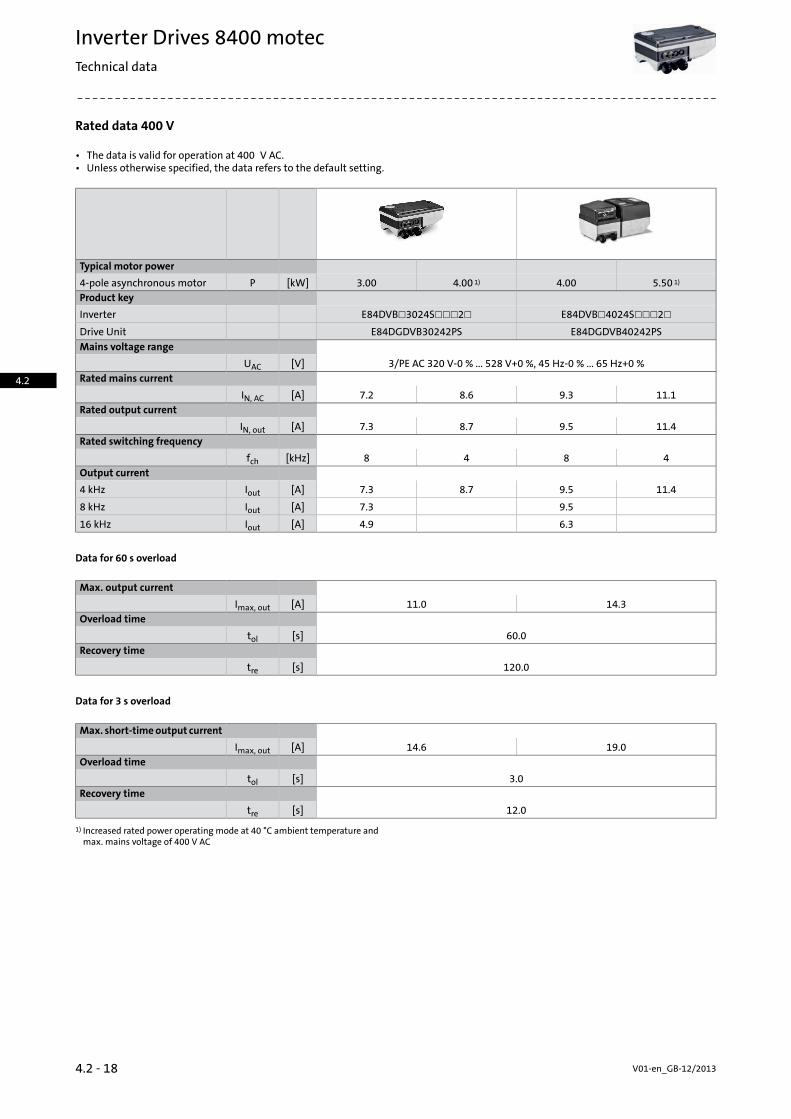
Rated data 400 V
• The data is valid for operation at 400 V AC.• Unless otherwise specified, the data refers to the default setting.
Typical motor power
5.50 1)4.004.00 1)3.00[kW]P4-pole asynchronous motorProduct key
E84DVB☐4024S☐☐☐2☐E84DVB☐3024S☐☐☐2☐Inverter
E84DGDVB40242PSE84DGDVB30242PSDrive UnitMains voltage range
3/PE AC 320 V-0 % ... 528 V+0 %, 45 Hz-0 % ... 65 Hz+0 %[V]UACRated mains current
11.19.38.67.2[A]IN, ACRated output current
11.49.58.77.3[A]IN, outRated switching frequency
4848[kHz]fchOutput current
11.49.58.77.3[A]Iout4 kHz
9.57.3[A]Iout8 kHz
6.34.9[A]Iout16 kHz
Data for 60 s overload
Max. output current
14.311.0[A]Imax, outOverload time
60.0[s]tolRecovery time
120.0[s]tre
Data for 3 s overload
Max. short-timeoutput current
19.014.6[A]Imax, outOverload time
3.0[s]tolRecovery time
12.0[s]tre
Increased rated power operating mode at 40 °C ambient temperature andmax. mains voltage of 400 V AC
1)
V01-en_GB-12/20134.2 - 18
Inverter Drives 8400 motecTechnical data
4.2

Rated data 400 V
• The data is valid for operation at 400 V AC.• Unless otherwise specified, the data refers to the default setting.
Typical motor power
5.50 1)4.004.00 1)3.00[kW]P4-pole asynchronous motorProduct key
E84DVB☐4024S☐☐☐2☐E84DVB☐3024S☐☐☐2☐Inverter
E84DGDVB40242PSE84DGDVB30242PSDrive UnitPower loss
0.140.11[kW]PVMass
5.33.5[kg]mMax. cable length
20[m]lmaxShielded motor cable 2)
Brake chopper rated data
Rated power, Brake chopper
4.03.0[kW]PNMax. output power, Brakechopper
5.54.5[kW]Pmax, 1Min. brake resistance
47.0100.0[Ω]Rmin
Dimensions
Dimensions
176135[mm]hHeight
195176[mm]bWidth
325261[mm]tDepth
Increased rated power operating mode at 40 °C ambient temperature andmax. mains voltage of 400 V AC
1)
Technically possible cable lengths, irrespective of EMC requirements2)
4.2 - 19V01-en_GB-12/2013
Inverter Drives 8400 motecTechnical data
4.2

Rated data 400 V
• The data is valid for operation at 400 V AC.• Unless otherwise specified, the data refers to the default setting.
Typical motor power
9.20 1)7.507.50 1)5.50[kW]P4-pole asynchronous motorProduct key
E84DVB☐7524S☐☐☐2☐E84DVB☐5524S☐☐☐2☐Inverter
E84DGDVB75242PSE84DGDVB55242PSDrive UnitMains voltage range
3/PE AC 320 V-0 % ... 528 V+0 %, 45 Hz-0 % ... 65 Hz+0 %[V]UACRated mains current
19.516.315.312.8[A]IN, ACRated output current
19.816.515.613.0[A]IN, outRated switching frequency
4848[kHz]fchOutput current
19.816.515.613.0[A]Iout4 kHz
16.513.0[A]Iout8 kHz
10.98.6[A]Iout16 kHz
Data for 60 s overload
Max. output current
24.719.5[A]Imax, outOverload time
60.0[s]tolRecovery time
120.0[s]tre
Data for 3 s overload
Max. short-timeoutput current
33.026.0[A]Imax, outOverload time
3.0[s]tolRecovery time
12.0[s]tre
Increased rated power operating mode at 40 °C ambient temperature andmax. mains voltage of 400 V AC
1)
V01-en_GB-12/20134.2 - 20
Inverter Drives 8400 motecTechnical data
4.2

Rated data 400 V
• The data is valid for operation at 400 V AC.• Unless otherwise specified, the data refers to the default setting.
Typical motor power
9.20 1)7.507.50 1)5.50[kW]P4-pole asynchronous motorProduct key
E84DVB☐7524S☐☐☐2☐E84DVB☐5524S☐☐☐2☐Inverter
E84DGDVB75242PSE84DGDVB55242PSDrive UnitPower loss
0.230.18[kW]PVMass
5.3[kg]mMax. cable length
20[m]lmaxShielded motor cable
Brake chopper rated data
Rated power, Brake chopper
9.27.56.65.5[kW]PNMax. output power, Brakechopper
9.27.5[kW]Pmax, 1Min. brake resistance
47.0[Ω]Rmin
Dimensions
Dimensions
176[mm]hHeight
195[mm]bWidth
325[mm]tDepth
Increased rated power operating mode at 40 °C ambient temperature andmax. mains voltage of 400 V AC
1)
Technically possible cable lengths, irrespective of EMC requirements2)
4.2 - 21V01-en_GB-12/2013
Inverter Drives 8400 motecTechnical data
4.2

The three units
Communication unitAs a drive package, the Inverter Drives 8400 motec is supplied pre-installed on thegearedmotor. If the8400motec is ordered separately, • Interface for I/Os and fieldbus linksit is easy to install on the motor or the wall using just four screws. • AS interface, CANopen, EtherCAT®, EtherNet/IP, PROFIBUS or
PROFINETThe flexibility offered by the 8400motec is underlined by itsmodularand cleverly designed structure, consisting of the "drive unit", "com-munication unit" and "wiring unit" modules.
• I/Os and on-board safety• Pluggable M12 connection system
If the 8400 motec is ordered individually, the various "units" to besupplied can be selected separately. Details on the functions of theindividual units:
Wiring Unit• Connections to the mains and to the drive• Flexible connection options such as cable glands and diverse plug-in connectorsDrive unit
• Connection for brake resistor• Inverter power section• Easy commissioning via DIP switch, potentiometer or diagnosisterminal
• Connection for spring-applied brake
• An easily changeable memory module• A large LED display to show statuses
Drive Unit
Communication Unit
Wiring Unit
Drive Unit
Communication Unit
Wiring Unit
8400 motec 4.0 to 7.5 kW8400 motec 0.37 to 3.0 kW
V01-en_GB-12/20134.2 - 22
Inverter Drives 8400 motecTechnical data
4.2

Drive Unit
Alongside the power section, the underside of the drive unit alsohouses several DIP switches and potentiometers, with which the in-verter can easily be commissioned. These allow the configuration,speed and ramp to be adjusted. The drive can, for example, then bequickly and easily adapted to match the system.
Dip switches on Drive Unit
For the purpose of diagnostics, you can plug in a diagnostic adapteralongside the statusdisplaywithouthaving todisassemble thedrive.Thanks to the potentiometer that can be accessed from above, youcan make speed settings while the motor is actually running.
Drive Unit diagnostic terminal Drive Unit diagnostic terminal
4.2 - 23V01-en_GB-12/2013
Inverter Drives 8400 motecTechnical data
4.2

Communication Unit
The communication modules support the following functions:• Control of the inverter via digital and analog signals• Control of the inverter via the fieldbus systems• Support for the "safe torque off" functionality• Connection options for sensors and actuators• The sensors can be powered by the internal 24 V supply• Connection options via cable glands and M12 connectors. A totalof up to 8 screwed connections / plugs can be used. Based on theirfunction, the individual communication units are equipped withthe corresponding connections as standard.
Communication Unit
Designs• Basic I/O• Standard I/O• Application I/O• AS-i• CANopen• EtherCAT®• EtherNet/IP• PROFIBUS• PROFINET
Wiring Unit
Thewiringunit forms the interfacebetween the variousmotor framesizes and inverters. In addition to this, it provides the flexibility intermsof connection options for power,motor, brake andbrake resist-ance.
The wiring unit also acts as a holder for various additional modulessuch as :• Wall mounting• Q5/0 plug-in moduleas Q5/0 plug connection or loop-through connection
• Q4/2 plug-in moduleas Q4/2 plug connection or loop-through connection
Wiring Unit• Q8/0 plug-in moduleas Q8/0 plug connection for the motor when wall mounted
• Integrated brake resistorfor braking operation via the integrated brake chopper
V01-en_GB-12/20134.2 - 24
Inverter Drives 8400 motecTechnical data
4.2

4.2 - 25V01-en_GB-12/2013
Inverter Drives 8400 motecTechnical data
4.2
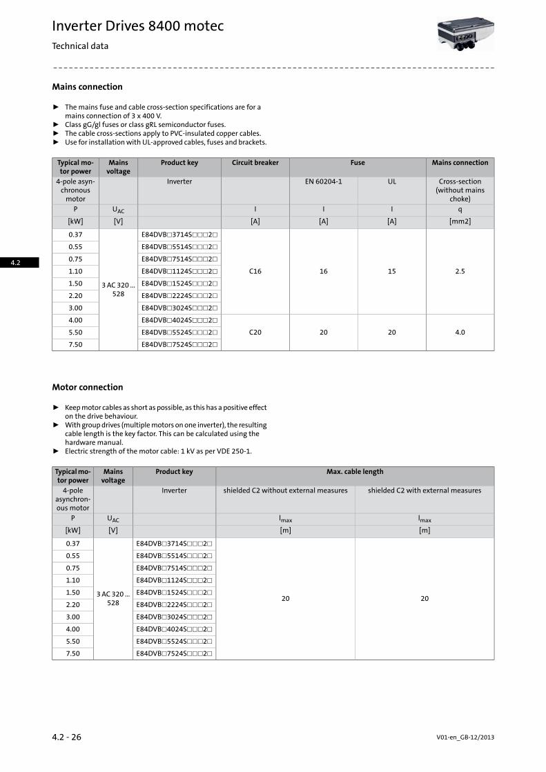
Mains connection
ƒ Themains fuse and cable cross-section specifications are for amains connection of 3 x 400 V.
ƒ Class gG/gl fuses or class gRL semiconductor fuses.ƒ The cable cross-sections apply to PVC-insulated copper cables.ƒ Use for installationwith UL-approved cables, fuses and brackets.
Mains connectionFuseCircuit breakerProduct keyMainsvoltage
Typical mo-tor power
Cross-section(without mains
choke)
ULEN 60204-1Inverter4-pole asyn-chronousmotor
qIIIUACP
[mm2][A][A][A][V][kW]
2.51516C16
E84DVB☐3714S☐☐☐2☐
3AC320 ...528
0.37
E84DVB☐5514S☐☐☐2☐0.55
E84DVB☐7514S☐☐☐2☐0.75
E84DVB☐1124S☐☐☐2☐1.10
E84DVB☐1524S☐☐☐2☐1.50
E84DVB☐2224S☐☐☐2☐2.20
E84DVB☐3024S☐☐☐2☐3.00
4.02020C20
E84DVB☐4024S☐☐☐2☐4.00
E84DVB☐5524S☐☐☐2☐5.50
E84DVB☐7524S☐☐☐2☐7.50
Motor connection
ƒ Keepmotor cables as short as possible, as this has apositive effecton the drive behaviour.
ƒ Withgroupdrives (multiplemotors onone inverter), the resultingcable length is the key factor. This can be calculated using thehardware manual.
ƒ Electric strength of the motor cable: 1 kV as per VDE 250-1.
Max. cable lengthProduct keyMainsvoltage
Typicalmo-tor power
shielded C2 with external measuresshielded C2 without external measuresInverter4-poleasynchron-ous motor
lmaxlmaxUACP
[m][m][V][kW]
2020
E84DVB☐3714S☐☐☐2☐
3AC320 ...528
0.37
E84DVB☐5514S☐☐☐2☐0.55
E84DVB☐7514S☐☐☐2☐0.75
E84DVB☐1124S☐☐☐2☐1.10
E84DVB☐1524S☐☐☐2☐1.50
E84DVB☐2224S☐☐☐2☐2.20
E84DVB☐3024S☐☐☐2☐3.00
E84DVB☐4024S☐☐☐2☐4.00
E84DVB☐5524S☐☐☐2☐5.50
E84DVB☐7524S☐☐☐2☐7.50
V01-en_GB-12/20134.2 - 26
Inverter Drives 8400 motecTechnical data
4.2

Connection diagrams
Wiring example for connecting Inverter Drives 8400 motec to 3 x 400V
4.2 - 27V01-en_GB-12/2013
Inverter Drives 8400 motecTechnical data
4.2

Control connections: Standard I/O
Mode
8400 motecProductAnalog inputs
1NumberSwitchable: voltage or current input
10 bitsResolution
0 ... 10V, 0/4 ... 20mAValue rangeDigital inputs
6 (5 + 1 controller enable)Number
PLC (IEC 61131-2)Switching level
11mAMax. input current
FunctionDigital outputs
1Number
PLC (IEC 61131-2)Switching level
50mAMax. output currentRelay
1Number
NO contactContact
250V, 3AAC connection
24V, 2A ... 240V, 0.16ADC connectionExternal 24 V DC supply
To support communication when the 400 V is switched offInternal 24 V DC supply
Max. 100 mA for inputs/outputs and sensor feedsInterfaces
CANopen
Fieldbus via communication unitExtensions
1 safe input for passive/active actuatorsSafety engineeringDrive interface
Via 2 digital inputs,Encoder inputHTL, 2-track,10 kHz
Additional connections
All connections are generally connected internally to terminals. Themost common connections of the Communication Unit already haveplug connectors. If additional connections are to be implemented,these can be designed as standard PG glands.
V01-en_GB-12/20134.2 - 28
Inverter Drives 8400 motecTechnical data
4.2

Control connections
Connection of analog inputs and outputs, Basic I/O
Connection of analog inputs and outputs, Standard I/O
4.2 - 29V01-en_GB-12/2013
Inverter Drives 8400 motecTechnical data
4.2

V01-en_GB-12/20134.2 - 30
Inverter Drives 8400 motecTechnical data
4.2

Memory module
All drive settings for the 8400 are stored on the memory module,which is a pluggablememory chip. Thememorymodule ensures thatdrives can be replaced quickly and without errors being made.
Product keyFeaturesMode
E84AYM20S/MMemory module• For 8400 BaseLine, 8400 motec• Packaging unit: 12 items
Safety engineering
The "safe torque off (STO)" safety function can be integrated into theCommunicationUnit in addition to the communicationmodule. Thiscombination is available with any bus.
PROFINET STOPROFIBUS STOEtherNet/IP STOEtherCAT STOCANopen STOAS-Interface STOCommunication moduleCertification
PLeEN ISO 13849-1Category 4
SIL 3EN 61800-5-2
SIL 3EN 62061
SIL 3IEC 61508Fail-safe state
Safe torque off
4.2 - 31V01-en_GB-12/2013
Inverter Drives 8400 motecModules
4.2

Communication modules
Various communicationmodules can be installed in the communica-tionunit. They serve to connect the L-force InverterDrives 8400motecto a bus system.
Overview
External 24 VDC supply
Safety STOAnalog inputsRelay outputsDigital outputsDigital inputsController en-able
NumberNumberNumberNumberNumberNumberNumberCommunicationmodule
121Basic I/O
11151Standard I/O
151AS-Interface
Application I/O
111151AS-Interface
STO
151CANopen
111151CANopen STO
1151EtherCAT
1111151EtherCAT STO
1151EtherNet/IP
1111151EtherNet/IPSTO
1151PROFIBUS
1111151PROFIBUS STO
1151PROFINET
1111151PROFINET STO
ƒ STO: Safe Torque Off
V01-en_GB-12/20134.2 - 32
Inverter Drives 8400 motecModules
4.2

Communication modules without fieldbus link
The following modules are available for controlling the 8400 motecvia digital signals:• Basic I/O• Standard I/O• Application I/O
The Basic I/O functionmodule provides the inverterwith aminimumnumber of digital inputs and outputs for themost basic applications.
The Standard I/O function module provides the inverter with an ex-tendednumberofdigital inputs andoutputs and is primarily intendedfor standard applications.
Basic I/O, Standard I/O or Application I/O
The Application I/O function module provides the inverter with oneadditional digital input andoutput over the Standard I/Oand is inten-ded for use with more complex applications.
Product keyNumber offree slots
FeaturesMode
Communication module
E84DGFCN☐NP8Basic I/O• 2 digital inputs• Controller enable• 1 relay
E84DGFCS☐NP8Standard I/O
• Controller enable• 5 digital inputs• 1 digital output• 1 analog input• 1 relay
E84DGFCX☐JP8Application I/O
• Controller enable• 6 digital inputs• 1 digital output• 2 analogue inputs (-10/0 to 10 V or 0/4 to 20 mA)• 1 relay
Standards and operating conditions
Product key
E84DGFCX☐JPE84DGFCS☐NPE84DGFCN☐NPMode
Application I/OStandard I/OBasic I/OCommunication moduleDegree of protection
IP65EN 60529Climatic conditions
1K3 (temperature: -30 °C ... +60 °C)Storage (EN 60721-3-1)
3K3 (temperature: -30°C ... +55°C)Operation (EN 60721-3-3)
2K3 (temperature: -30 °C ... +75 °C)Transport (EN 60721-3-2)Insulation voltage to reference earth/PE
50.0[V]UACEN 61800-5-1
Pin assignment
In the case of the communicationmodules without fieldbus connec-tion, only the variant "I/O terminal" is provided. It is connected bymeans of the cable gland.
4.2 - 33V01-en_GB-12/2013
Inverter Drives 8400 motecModules
4.2

Communication module: AS-Interface (AS-i)
The AS-Interface communication module enables you to control the8400 motec using digital control signals. The AS-i bus system hasbecome the established solution for transferring digital signals onthe lowest field level. It is designed for applications that donot requirethe use of powerful fieldbus systems.
The advantages of this system are:• Easy handling and commissioning• Less wiring effort• Can be easily integrated into existing systems
Communication module: AS-Interface (AS-i)• Cost reductions
Product keyNumber offree slots
FeaturesMode
Communication module
E84DGFCA☐NP6AS-Interface
• Acyclical polling of diagnostic data• Acyclical reading and writing of parameter sets• Cyclical drive control• Cyclical reading andwriting of individual parameters• Controller enable• 5 digital inputs• 1 digital output• 4 digital inputs for when power is supplied via theAS-i bus and there is no mains supply
E84DGFCA☐JP6AS-Interface STO
• Acyclical polling of diagnostic data• Acyclical reading and writing of parameter sets• Cyclical drive control• Cyclical reading andwriting of individual parameters• Controller enable• 5 digital inputs• 1 digital output• 4 digital inputs for when power is supplied via theAS-i bus and there is no mains supply
• 1 analog input• 1 relay• Safety function STO
Standards and operating conditions
Product key
E84DGFCA☐JPE84DGFCA☐NPMode
AS-Interface STOAS-InterfaceCommunication moduleDegree of protection
IP65EN 60529Climatic conditions
1K3 (temperature: -30 °C ... +60 °C)Storage (EN 60721-3-1)
3K3 (temperature: -30°C ... +55°C)Operation (EN 60721-3-3)
2K3 (temperature: -30 °C ... +75 °C)Transport (EN 60721-3-2)Insulation voltage to reference earth/PE
50.0[V]UACEN 61800-5-1
V01-en_GB-12/20134.2 - 34
Inverter Drives 8400 motecModules
4.2

Communication module: AS-Interface (AS-i)
Technical data
Product key
E84DGFCA☐JPE84DGFCA☐NPCommunication moduleStandard
EN 50295 / IEC 62026-2Communication
AS interface V3.0Communication profile
2-wire cable for data and auxiliary powerMediumNetwork topology
Free topology (line, ring, tree, star)Node
Slave (single or dual)max. 31 standard slaves or safe slavesMax. 62 A/B Slaves
Number of bus nodes
1 ... 31Max. cable length
100 without repeaters / extenders[m]lmaxper bus segment300 including 2 repeaters / extenders500 only for star-shaped mains including repeaters / extenders
Baud rate
167 (gross value)[kBit/s]53 (net with data transfer efficiency = 32%)
Rated voltage
24.0[V]UN, DCDC
Pin assignment
The connector is A-coded and can be connected using an AS-i cablefeaturing penetration technology.
Can be quickly connected to the bus and certain inputs/outputs via5-pin M12 connector of the Communication Unit.
SlotProduct keyVariantMode
B4B3B2B1A4A3A2A1Communica-tion module
Communicationmodule
ASiLED
E84DGFCAANPI/O terminalAS-Interface DI3
DI4DI1DI2
E84DGFCA9NPI/O 2xM12
E84DGFCAAJPI/O terminalAS-Interface STO DI3
DI4DI1DI2
E84DGFCA9JPI/O 2xM12
ƒ DI1 to DI4= digital inputsƒ LED= status display for bus communication
4.2 - 35V01-en_GB-12/2013
Inverter Drives 8400 motecModules
4.2

Communication module: CANopen
TheCANopen communicationmodule allows you to control the8400motec by sending digital control signals via the "CANopen“ bus sys-tem.
The advantages of this system are:• Straightforward, yet extremely powerful, bus system• Cost-effective• Easy system integration, as there is a wide range of sensors andactuators available on the market
Communication module: CANopen
Product keyNumber offree slots
FeaturesMode
Communication module
E84DGFCC☐NP6CANopen
• Addressing via DIP switches or parameters• Internal 24 V DC supply• Controller enable• 5 digital inputs• 1 digital output
E84DGFCC☐JP6CANopen STO
• Addressing via DIP switches or parameters• Internal 24 V DC supply• Controller enable• 5 digital inputs• 1 digital output• 1 analog input• 1 relay• Safety function STO
Standards and operating conditions
Product key
E84DGFCC☐JPE84DGFCC☐NPMode
CANopen STOCANopenCommunication moduleDegree of protection
IP65EN 60529Climatic conditions
1K3 (temperature: -30 °C ... +60 °C)Storage (EN 60721-3-1)
3K3 (temperature: -30°C ... +55°C)Operation (EN 60721-3-3)
2K3 (temperature: -30 °C ... +75 °C)Transport (EN 60721-3-2)Insulation voltage to reference earth/PE
50.0[V]UACEN 61800-5-1
V01-en_GB-12/20134.2 - 36
Inverter Drives 8400 motecModules
4.2

Communication module: CANopen
Technical data
Product key
E84DGFCC☐JPE84DGFCC☐NPCommunication moduleCommunication
DIN ISO 11898Medium
CANopen, DS301 V4.02Communication profileLenze system bus
Baud rate
20[kBit/s]b501252505008001000
Node
SlaveMulti-master
Network topology
Line with terminating resistors (120 ohm) at both endsNumber of logical process datachannels
2 "send" PDOs and 2 "receive" PDOs (each with 1 - 8 bytes)Number of logic parameter datachannels
Max. 2 server SDO channels (with 1 - 8 bytes)Number of bus nodes
63Max. cable length
17 for 1000 kbps[m]lmaxper bus segment40 for 800 kbps110 for 500 kbps290 for 250 kbps630 for 125 kbps1500 for 50 kbps3900 for 20 kbps8000 for 10 kbps
Rated voltage
24.0[V]UN, DCDC
Pin assignment
The connector is A-coded and can be connected using a 5-pole con-nection M12.
Can be quickly connected to the bus and certain inputs/outputs via5-pin M12 connector of the Communication Unit.
SlotProduct keyVariantMode
B4B3B2B1A4A3A2A1Communica-tion module
Communicationmodule
CAN-out
CAN-in
E84DGFCCANPI/O terminalCANopen DI3
DI4DI1DI2
E84DGFCC9NPI/O 2xM12
E84DGFCCAJPI/O terminalCANopen STO DI3
DI4DI1DI2
E84DGFCC9JPI/O 2xM12
ƒ DI1 to DI4= digital inputs
4.2 - 37V01-en_GB-12/2013
Inverter Drives 8400 motecModules
4.2

EtherCAT® communication module
With the EtherCAT® communicationmodule, the InverterDrives 8400motec supports end-to-end communication from the field level rightthrough to company management level.
The benefits of this system include:• Fieldbus system capable of handling large data volumes• Use of IT standards• Integrated switchallowsdirect loopingof EtherCATvia the inverters• Integrated I/Onode. Capable of communicationand reading inputseven when the 400V supply us switched off.
EtherCAT® communication module• Option to connect an external 24V supply
Product keyNumber offree slots
FeaturesMode
Communication module
E84DGFCT☐NP5EtherCAT
• Support for the "Distributed clocks" (DC) functionalityfor synchronisation via fieldbus
• Link / Activity• PDO transfer with CoE (CANopen over EtherCAT)• Cycle times: 1 ms or a whole multiple of 1 ms; max-imum 15ms when using "distributed clocks" (DC)
• 4 LEDs for status display• Controller enable• 5 digital inputs• 1 digital output
E84DGFCT☐JP5EtherCAT STO
• Support for the "Distributed clocks" (DC) functionalityfor synchronisation via fieldbus
• Link / Activity• PDO transfer with CoE (CANopen over EtherCAT)• Cycle times: 1 ms or a whole multiple of 1 ms; max-imum 15ms when using "distributed clocks" (DC)
• 4 LEDs for status display• Controller enable• 5 digital inputs• 1 digital output• 1 analog input• 1 relay• Safety function STO
Standards and operating conditions
Product key
E84DGFCT☐JPE84DGFCT☐NPMode
EtherCAT STOEtherCATCommunication moduleDegree of protection
IP65EN 60529Climatic conditions
1K3 (temperature: -30 °C ... +60 °C)Storage (EN 60721-3-1)
3K3 (temperature: -30°C ... +55°C)Operation (EN 60721-3-3)
2K3 (temperature: -30 °C ... +75 °C)Transport (EN 60721-3-2)Insulation voltage to reference earth/PE
50.0[V]UACEN 61800-5-1
V01-en_GB-12/20134.2 - 38
Inverter Drives 8400 motecModules
4.2

EtherCAT® communication module
Technical data
Product key
E84DGFCT☐JPE84DGFCT☐NPCommunication moduleCommunication
CAT5e S/FTP according to ISO/ICE11801 (2002)Medium
CoE (CANopen over EtherCAT)Communication profileBaud rate
100[MBit/s]bNode
SlaveNetwork topology
LineSwitch
Number of logical process datachannels
1Process data words (PCD)
1 ... 10 (max. 20 bytes, 16 bits/word)to the master
1 ... 8 (max. 16 bytes, 16 bits/word)from the masterParameter data
128[Byte]Max. mailbox size for CoE transferNumber of bus nodes
Max. 65535Max. cable length
100[m]lmaxbetween two nodesRated voltage
24.0[V]UN, DCDC
Pin assignment
The connector is A-coded and can be connected using a 5-pole con-nection M12.
Can be quickly connected to the bus and certain inputs/outputs via5-pin M12 connector of the Communication Unit.
SlotProduct keyVariantMode
B4B3B2B1A4A3A2A1Communica-tion module
Communicationmodule
EC-outEC-inLED
E84DGFCTANPI/O terminalEtherCAT DI1
DI2E84DGFCT9NPI/O 1xM12
E84DGFCTAJPI/O terminalEtherCAT STO DI1
DI2E84DGFCT9JPI/O 1xM12
ƒ DI1 to DI4= digital inputsƒ LED= status display for bus communication
4.2 - 39V01-en_GB-12/2013
Inverter Drives 8400 motecModules
4.2

EtherNet/IP communication module
EtherNet/IP communication module
Product keyNumber offree slots
FeaturesMode
Communication module
E84DGFCG☐NP5EtherNet/IP
• Supports multicast messages, UCMM, ACD,BOOTP/DHCP, VLAN-Tagging/DSCP
• Internal 24 V DC supply• 4 LEDs for status display• Controller enable• 5 digital inputs• 1 digital output
E84DGFCG☐JP5EtherNet/IP STO
• Supports multicast messages, UCMM, ACD,BOOTP/DHCP, VLAN-Tagging/DSCP
• Internal 24 V DC supply• 4 LEDs for status display• Controller enable• 5 digital inputs• 1 digital output• 1 analog input• 1 relay• Safety function STO
Standards and operating conditions
Product key
E84DGFCG☐JPE84DGFCG☐NPMode
EtherNet/IP STOEtherNet/IPCommunication moduleDegree of protection
IP65EN 60529Climatic conditions
1K3 (temperature: -25 °C ... +60 °C)Storage (EN 60721-3-1)
3K3 (temperature: -10°C ... +55°C)Operation (EN 60721-3-3)
2K3 (temperature: -25 °C ... +70 °C)Transport (EN 60721-3-2)Insulation voltage to reference earth/PE
50.0[V]UACEN 61800-5-1
V01-en_GB-12/20134.2 - 40
Inverter Drives 8400 motecModules
4.2

EtherNet/IP communication module
Technical data
Product key
E84DGFCG☐JPE84DGFCG☐NPCommunication moduleCommunication
CAT5e S/FTP according to ISO/ICE11801 / EN50173Medium
EtherNET/IP, AC DriveCommunication profileBaud rate
10/100 (full duplex/half duplex)[MBit/s]bNode
Slave (Adapter)Network topology
Tree, star and lineProcess data words (PCD)
1 ... 1616 BitNumber of bus nodes
max. 254 im SubnetzMax. cable length
100[m]lmaxbetween two nodesRated voltage
24.0[V]UN, DCDC
Pin assignment
The connector is D-coded and can be connected using a 5-pole M12connection.
Can be quickly connected to the bus and certain inputs/outputs via5-pin M12 connector of the Communication Unit.
SlotProduct keyVariantMode
B4B3B2B1A4A3A2A1Communica-tion module
Communicationmodule
EN-outEN-inLED
E84DGFCGANPI/O terminalEtherNet/IP DI1
DI2E84DGFCG9NP
E84DGFCGAJPI/O 1xM12EtherNet/IP STO DI1
DI2E84DGFCG9JP
ƒ DI1 to DI4= digital inputsƒ LED= status display for bus communication
4.2 - 41V01-en_GB-12/2013
Inverter Drives 8400 motecModules
4.2

PROFIBUS communication modules
When combined with the PROFIBUS communication module, the8400motec supports PROFIBUS, themostwidelyused fieldbus systemtoday.
The advantages of this system are:• Widely used and extremely powerful fieldbus system• Integrated I/Onode. Capable of communicationand reading inputseven when the 400 V supply is switched off.
• Option of connecting an external 24V supply
PROFIBUS communication modules
Product keyNumber offree slots
FeaturesMode
Communication module
E84DGFCP☐NP5PROFIBUS
• DPVO: basic functionalities such as cyclical data ex-change and diagnostics
• DPV1: supportsacyclical dataexchange forparametersetting, operation and alarm handling
• Internal 24 V DC supply• 4 LEDs for status display• Controller enable• 5 digital inputs• 1 digital output
E84DGFCP☐JP5PROFIBUS STO
• DPVO: basic functionalities such as cyclical data ex-change and diagnostics
• DPV1: supportsacyclical dataexchange forparametersetting, operation and alarm handling
• Internal 24 V DC supply• 4 LEDs for status display• Controller enable• 5 digital inputs• 1 digital output• 1 analog input• 1 relay• Safety function STO
Standards and operating conditions
Product key
E84DGFCP☐JPE84DGFCP☐NPMode
PROFIBUS STOPROFIBUSCommunication moduleDegree of protection
IP65EN 60529Climatic conditions
1K3 (temperature: -30 °C ... +60 °C)Storage (EN 60721-3-1)
3K3 (temperature: -30°C ... +55°C)Operation (EN 60721-3-3)
2K3 (temperature: -30 °C ... +75 °C)Transport (EN 60721-3-2)Insulation voltage to reference earth/PE
50.0[V]UACEN 61800-5-1
V01-en_GB-12/20134.2 - 42
Inverter Drives 8400 motecModules
4.2

PROFIBUS communication modules
Technical data
Product key
E84DGFCP☐JPE84DGFCP☐NPCommunication moduleCommunication
RS 485Medium
PROFIBUS-DP-V0 (DRIVECOM)Communication profilePROFIBUS-DP-V1 (PROFIdrive)
Baud rate
9.6 ... 12 000 (automatic detection)[kBit/s]bNode
SlaveNetwork topology
with repeater: line or treewithout repeater: line
Process data words (PCD)
1 ... 816 BitDP user data length
Optional parameter channel (4 words) + process data wordsAcyclic parameter data channel (DP-V1): max 240 bytes
Number of bus nodes
31 slaves + 1 master per bus segmentWith repeaters: 125
Max. cable length
1200 (depending on the baud rate and the cable type used)[m]lmaxper bus segmentRated voltage
24.0[V]UN, DCDC
Pin assignment
The connector is B-codiert codedand canbe connectedusinga5-poleconnection M12.
Can be quickly connected to the bus and certain inputs/outputs via5-pin M12 connector of the Communication Unit.
SlotProduct keyVariantMode
B4B3B2B1A4A3A2A1Communica-tion module
Communicationmodule
PB-outPB-inLED
E84DGFCPANPI/O terminalPROFIBUS DI1
DI2E84DGFCP9NPI/O 1xM12
E84DGFCPAJPI/O terminalPROFIBUS STO DI1
DI2E84DGFCP9JPI/O 1xM12
ƒ DI1 to DI4= digital inputsƒ LED= status display for bus communication
4.2 - 43V01-en_GB-12/2013
Inverter Drives 8400 motecModules
4.2

PROFINET communication modules
With thePROFINET communicationmodule, the8400motec supportsa fieldbus system for continuous communication from the field levelright through to company management level.
The benefits of this system include:• Fieldbus system capable of handling large data volumes• Use of IT standards• Integrated switch allows direct looping of PROFINET via the invert-ers
• Integrated I/Onode. Capable of communicationand reading inputseven when the 400 V supply us switched off.
PROFINET communication modules
• Option to connect an external 24 V supply
Product keyNumber offree slots
FeaturesMode
Communication module
E84DGFCR☐NP5PROFINET
• Automatic detection of the 100 Mbps baud rate• Creationof a line topology through integrated2-portswitch
• Support for I&M0 to4 functionality for identificationof the standard device
• Link / Activity• 4 LEDs for status display• Controller enable• 5 digital inputs• 1 digital output
E84DGFCR☐JP5PROFINET STO
• Automatic detection of the 100 Mbps baud rate• Creationof a line topology through integrated2-portswitch
• Support for I&M0 to4 functionality for identificationof the standard device
• Link / Activity• 4 LEDs for status display• Controller enable• 5 digital inputs• 1 digital output• 1 analog input• 1 relay• Safety function STO
Standards and operating conditions
Product key
E84DGFCR☐JPE84DGFCR☐NPMode
PROFINET STOPROFINETCommunication moduleDegree of protection
IP65EN 60529Climatic conditions
1K3 (temperature: -30 °C ... +60 °C)Storage (EN 60721-3-1)
3K3 (temperature: -30°C ... +55°C)Operation (EN 60721-3-3)
2K3 (temperature: -30 °C ... +75 °C)Transport (EN 60721-3-2)Insulation voltage to reference earth/PE
50.0[V]UACEN 61800-5-1
V01-en_GB-12/20134.2 - 44
Inverter Drives 8400 motecModules
4.2

PROFINET communication modules
Technical data
Product key
E84DGFCR☐JPE84DGFCR☐NPCommunication moduleCommunication
CAT5e S/FTP according to ISO/ICE11801 (2002)Medium
PROFINET RT Conf. Class BCommunication profileBaud rate
100[MBit/s]bNode
Slave (Device)Network topology
Tree, star and lineNumber of logical process datachannels
1Process data words (PCD)
1 ... 816 BitMax. cable length
100[m]lmaxbetween two nodesRated voltage
24.0[V]UN, DCDC
Pin assignment
The connector is D-coded and can be connected using a 5-pole M12connection.
Can be quickly connected to the bus and certain inputs/outputs via5-pin M12 connector of the Communication Unit.
SlotProduct keyVariantMode
B4B3B2B1A4A3A2A1Communica-tion module
Communicationmodule
PN-outPN-inLED
E84DGFCRANPI/O terminalPROFINET DI1
DI2E84DGFCR9NPI/O 1xM12
E84DGFCRAJPI/O terminalPROFINET STO DI1
DI2E84DGFCR9JPI/O 1xM12
ƒ DI1 to DI4= digital inputsƒ LED= status display for bus communication
4.2 - 45V01-en_GB-12/2013
Inverter Drives 8400 motecModules
4.2

V01-en_GB-12/20134.2 - 46
Inverter Drives 8400 motecModules
4.2

Wiring Unit versions
Thewiringunit forms the interfacebetween the variousmotor framesizes and inverters. In addition to this, it provides the flexibility intermsof connection options for power,motor, brake andbrake resist-ance. The correctwiringunit is selectedbasedon the size of themotorand the terminal box.
Wiring Unit
Product key
E84DGVN5EE84DGVN4EE84DGVN3EE84DGVN2EE84DGVN1EMode
Wiring UnitFeatures
••••• ForE84DVB☐5524 to7524
ForE84DVB☐4024 to7524
ForE84DVB☐2224 to3024
ForE84DVB☐5514 to1524
ForE84DVB☐3714 to1124
••••• For motor framesize 132
For motor framesizes 080, 090100 and 112
For motor framesizes 080, 090100 and 112
For motor framesizes 080, 090and 100
For motor framesizes 063and071
• •Enclosure: IP66 Enclosure: IP66••• Enclosure: IP66Enclosure: IP66Enclosure: IP66
Connector modules
Mounting ofplug-in module left
Mounting ofplug-in module right
Screwed sockets for themains connectionare includedon the InverterDrives 8400 motec as standard. Alternatively, Q4, Q5 or Q8 plug-inmodules can be used. Thanks to the universal connection optionsoffered by the modules, a supply bus can be set up using plugs andcouplings without the need for any external accessories.
HAN connector
Product keyFeaturesMode
E84DZEVBLANPPlug-in module 1 x Q5/0, left
• 5 power contacts and PE: 16 A/400 V• Applications with external mains distributor
E84DZEVBRANPPlug-in module 1 x Q5/0, right
4.2 - 47V01-en_GB-12/2013
Inverter Drives 8400 motecAccessories
4.2

HAN connector
Product keyFeaturesMode
E84DZEVBLAFPPlug-in module 2 x Q5/0, left
• 5 power contacts and PE: 16 A/400 V• Applications with mains loops
E84DZEVBRAFPPlug-in module 2 x Q5/0, right
E84DZEVBLPNPPlug-in module 1 x Q4/2, left
• 4 power contacts and PE: 32 A/400 V• 2 control contacts: 10 A/24 V• Applications with external mains distributor
E84DZEVBRPNPPlug-in module 1 x Q4/2, right
E84DZEVBLPRPPlug-in module 2 x Q4/2, left
• 4 power contacts and PE: 32 A/400 V• 2 control contacts: 10 A/24 V• Applications with mains loops
E84DZEVBRPRPPlug-in module 2 x Q4/2, right
E84DZEVBLCNPPlug-in module 1 x Q8/0, left
• 6 power contacts and PE: 25 A/400 V• Motor connection with wall mounting
E84DZEVBRCNPPlug-in module 1 x Q8/0, right
V01-en_GB-12/20134.2 - 48
Inverter Drives 8400 motecAccessories
4.2

Internal brake resistor
An internal brake resistor canalsobemountedon the right-hand sideof the 8400 motec instead of the plug-in modules.
Internal brake resistor
Thermal capa-city
Rated powerRated resistanceProduct keyMains voltageTypical motorpower
Brake resistorInverter4-pole asyn-chronous motor
CthPNRNUACP
[KWs][kW][Ω][V][kW]
0.2815.0
220.0E84DZEW220R
E84DVB☐3714S☐☐☐2☐
3 AC 320 ... 528
0.37
E84DVB☐5514S☐☐☐2☐0.55
E84DVB☐7514S☐☐☐2☐0.75
E84DVB☐1124S☐☐☐2☐1.10
E84DVB☐1524S☐☐☐2☐1.50
100.0E84DZEW100RE84DVB☐2224S☐☐☐2☐2.20
E84DVB☐3024S☐☐☐2☐3.00
47.0E84DZEW047R
E84DVB☐4024S☐☐☐2☐4.00
E84DVB☐5524S☐☐☐2☐5.50
E84DVB☐7524S☐☐☐2☐7.50
Wall mounting
The wall mount is used to attached is the inverter to be machinechassis or the wall. The design offers IP65 protection and is easy toattach.
Wall mounting
Product key
E84DZMAWE1Mode
Wall mountingFeatures
• Degree of protection IP65• Simple mounting
4.2 - 49V01-en_GB-12/2013
Inverter Drives 8400 motecAccessories
4.2

Brake resistors
Anexternal brake resistor is required tobrakehighmoments of inertiaor in the event of prolongedoperation in generatormode; this resistorconverts braking energy into heat.
The brake resistors recommended in the table below have been di-mensioned for approx. 1.5 times the regenerative power,with a cycletime of 15/135 s (brake/rest ratio). These brake resistors generallymeet the usual requirements of standard applications.
The brake resistors are fitted with a thermostat (potential-free NCcontact).
Brake resistor
MassDimensionsThermalcapacity
Ratedpower
Ratedresist-ance
Product keyMainsvoltage
Typicalmo-tor power
Brake resistorInverter4-poleasynchron-ous motor
mh x b x tCthPNRNUACP
[kg][mm][KWs][kW][Ω][V][kW]
2.0382 x 124 x 12253.0350.0180.0ERBS180R350W
E84DVB☐3714S☐☐☐2☐
3AC320 ...528
0.37
E84DVB☐5514S☐☐☐2☐0.55
E84DVB☐7514S☐☐☐2☐0.75
E84DVB☐1124S☐☐☐2☐1.10
E84DVB☐1524S☐☐☐2☐1.50
3.0566 x 124 x 12294.0625.0100.0ERBS100R625WE84DVB☐2224S☐☐☐2☐2.20
E84DVB☐3024S☐☐☐2☐3.00
2.33.9
400 x 110 x 105710 x 110 x 105
60.0120
400.0800.0
47.047.0
ERBS047R400WERBS047R800W
E84DVB☐4024S☐☐☐2☐4.00
E84DVB☐5524S☐☐☐2☐5.50
E84DVB☐7524S☐☐☐2☐7.50
V01-en_GB-12/20134.2 - 50
Inverter Drives 8400 motecAccessories
4.2

USB diagnostic adapter
The operation, parameter setting and diagnostics of the InverterDrives 8400 and the Servo Drives 9400 via the L-force diagnostics ismade with the keypad X400 or a PC. The connection of a PC can bemade via a USB interface and the USB diagnostic adapter.
For connecting theUSBdiagnostic adapterwith the L-forcediagnosticsinterface (DIAG) tat the inverter, three different connecting cablesare separately available in the lengths 2.5 m, 5 m and 10 m. Theconnection can be established during operation. The engineeringtools EASY Starter or Engineer can be used to carry out the operation,parameter setting or diagnostics of the inverters. Both tools havesimple intuitive surfaces. This enables a quick and easy commission-ing.
Optionally to the USB diagnostic adapter, the PC system bus adaptercan be used. For this purpose, a CANopen interfacemust be availableat the inverter.
USB diagnostic adapter incl.connecting cable to the PC
ƒ The engineering tools EASY Starter or Engineer are used for oper-ation, parameter setting and diagnostics of the inverters.
Product keyFeaturesMode
E94AZCUSUSB diagnostic adapter
• Input-side voltage supply via USB connection on PC• Output-side voltage supply via inverter's diagnosticinterface
• Diagnostic LEDs• Electrical isolation of PC and inverter• Hot-pluggable
Connecting cables for USB diagnostic adapter
Product keyFeaturesMode
EWL0070
Connecting cable forUSBdiagnostic adapter
• Length: 2.5 m
EWL0071• Length: 5 m
EWL0072• Length: 10 m
4.2 - 51V01-en_GB-12/2013
Inverter Drives 8400 motecAccessories
4.2

Diagnosis terminal
The diagnosis terminal can be used as an alternative to a PC if youare looking for an easy way to operate the inverter, set parametersor carry out diagnostics locally. The structured menus and plain textdisplay provide quick access to data.The diagnosis terminal can be plugged into the inverter's L-forcediagnostic interface (DIAG) from the outside.
Diagnosis terminal
Product keySlotFeaturesMode
EZAEBK2003DIAGDiagnosis terminal
• Diagnosis terminal inside robust housing• incl. 2.5 m cable• Degree of protection IP20• For 8400 motec and protec.
Switch/potentiometer unit
The switch/potentiometer unit is fitted directly to the 8400 motecor in a different position within the system. An analogue setpointcan be specified with the switch/potentiometer unit and the controlconnections integrated in the inverter by using the integrated poten-tiometer; the rotary switch can, for example, be used to start/stopthe drive or change the direction of rotation.The switch/potentiometer unit is supplied with a 2.5 m connectioncable.
Switch/potentiometer unit
Product keyMode
E82ZBUSwitch/potentiometer unit(IP65)
V01-en_GB-12/20134.2 - 52
Inverter Drives 8400 motecAccessories
4.2

System cables
For connection of the motor, Lenze provides finished hybrid cables.They are optimally matched to the connection between the DrivePackage components. Motor connection, blower connection, brakeconnection and temperaturemonitoring are integrated in the cables.Cables up to a length of 100 m can be selected in increments of 0.1m.
10-pole cables
Availablewith cross-sections 1.52 and 2.52with connection for brakeor thermal contact.
4.2 - 53V01-en_GB-12/2013
Inverter Drives 8400 motecAccessories
4.2

8-pole cables
Available with cross-sections 1.52 and 2.52 2with connection forbrake and thermal contact.
V01-en_GB-12/20134.2 - 54
Inverter Drives 8400 motecAccessories
4.2

4.2 - 55V01-en_GB-12/2013
Inverter Drives 8400 motecAccessories
4.2

V01-en_GB-12/20134.2 - 56
Inverter Drives 8400 motecAccessories
4.2

MD three-phase ACmotors0.12 to 22 kW
Motors


5.7 - 4List of abbreviationsGeneral information
5.7 - 5Product key
5.7 - 6Product information
5.7 - 7Functions and features
5.7 - 11Motor – inverter assignment
5.7 - 13Dimensioning
5.7 - 15Standards and operating conditionsTechnical data
5.7 - 16Permissible radial and axial forces
5.7 - 18Rated data for 50 Hz
5.7 - 20Rated data for 60 Hz
5.7 - 22Rated data for 87 Hz
5.7 - 24Dimensions, self-ventilated (4-pole)
5.7 - 30Dimensions, forced ventilated (4-pole)
5.7 - 36Dimensions, 8400 motec inverter
5.7 - 39Spring-applied brakesAccessories
5.7 - 51Resolver
5.7 - 52Incremental encoder and SinCos absolute value encoder
5.7 - 53Blowers
5.7 - 55Temperature monitoring
5.7 - 57Terminal box
5.7 - 58Plug connectors
5.7 - 58ICN connector
5.7 - 63M12 connector
5.7 - 64HAN connector
MD three-phase AC motorsContents
5.7

List of abbreviations
Max. mains voltage[V]UmaxEfficiency[%]η100 %Efficiency[%]η75 % Min. mains voltage[V]Umin
Rated voltage[V]UN, ΔEfficiency[%]η50 %Power factorcos ϕ Rated voltage[V]UN, YRated current[A]INMax. current consumption[A]ImaxMoment of inertia[kgcm²]JMass[kg]mStarting torque[Nm]MaStalling torque[Nm]MbMax. torque[Nm]MmaxRated torque[Nm]MNRated speed[r/min]nNRated power[kW]PNMax. power input[kW]Pmax
Communauté EuropéenneCECanadian Standards AssociationCSADeutsches Institut für Normung e.V.DINElectromagnetic compatibilityEMCEuropean standardENInternational Electrotechnical CommissionIECInternational Mounting CodeIMInternational Protection CodeIPNational Electrical Manufacturers AssociationNEMAUnderwriters Laboratory Listed ProductULUnderwriters Laboratory Recognized ProductURVerband deutscher Elektrotechniker (Association ofGerman Electrical Engineers)
VDE
China Compulsory CertificateCCCCertificate for Russian FederationGOSTCombined certification marks of UL for the USA andCanada
cURus
Certificate for UkraineUkrSEPRO
Lenze | V02-en_GB-04/20145.7 - 4
MD three-phase AC motorsGeneral information
5.7

Product key
5.7 - 5Lenze | V02-en_GB-04/2014
MD three-phase AC motorsGeneral information
5.7

Product information
For a long time now, three-phase AC motors from Lenze have beenestablished in virtually all industrial sectors. Based onourmany yearsof experience in the field of drive and automation technology, wehavedevelopedmotors,whichwill ensure that yourdemands in termsof productivity, quality and availability are perfectly met.Three-phase AC motors from the L-force series are primarily charac-terisedby their comprehensivemodularity. Thewidevarietyof optionsallows you to precisely adjust the drive characteristics in line withyour application. We call this Rightsizing.
OptionsL-force MD three-phase AC motors are available in a power rangefrom 0.12 to 22 kW and comply with efficiency class IE1 (standardefficiency) as per IEC 60034-30.
• Various brake sizes – each available with several braking torques– can be combined with the three-phase AC motors.
• The LongLife version of the brake can easily reach 10 x 106
switching cycles.Basic versions• A resolver and various incremental and absolute value encoderscan be fitted for speed and position detection.
• The motors feature B3, B5 and B14 designs and dimensionsstandardised in line with IEC 60072-1 and/or DIN EN 50347whichmakes then suitable for universal use. • For fast commissioning, themotors are also availablewith connect-
ors for the power connection, brake, blower and feedback.• The thermal sensors integrated as standard allow for permanenttemperature monitoring and are coordinated to the motor wind-ing's temperature class F (155 °C).
• Instead of an integral fan, the motor can optionally be equippedwith a blower. No torque reduction is then necessary, even atspeeds below 20 Hz.• Themotors of the basic version are adapted to ambient conditions
by enclosure IP55. • For drive tasks in decentralised applications, the motor can beordered with the motec inverter connected to the terminal box.• In toughoperating conditions, the surface and corrosionprotection
system is provided to reliably protect the motor from aggresivemedia.
• The motors are available with cURus, GOST-R, CCC and UkrSeproapproval.
Lenze | V02-en_GB-04/20145.7 - 6
MD three-phase AC motorsGeneral information
5.7

Functions and features
Size
090080071063MotorDesign
B3B5B14
Shaft journal
24 x 5019 x 4014 x 3011 x 23[mm]d x lSpring-applied brake
Standard or LongLife designStandard or LongLife designDesignReduced, standard or increased braking torqueReduced or standard braking torque
With rectifierWith rectifierWith manual release leverWith manual release lever
Low noiseLow noiseFeedback
ResolverDesignIncremental encoder
Absolute value encoder (multi-turn)Temperature sensor
TKOThermal contact
KTY83-110Thermal detectorKTY84-130
PTCPTC thermistorMotor connection
Terminal boxPower connectionICN connector
HAN10E connectorHANmodular connector
Terminal boxBrake connectionICN connector
HANmodular connectorHAN10E connector
Terminal boxBlower connectionICN connector
Terminal boxFeedback connectionICN connector
Terminal boxTemperature sensor connectionTKO or PTC at connector in the power connectionKTY at connector in the feedback connection
Shaft bearings
Standard motors (B3, B5, B14): side BPosition of the locating bearingMotors for gearbox direct mounting: side A
Deep-groove ball bearing with high-temperature resistant grease, 2 sealing discs or cover platesBearing typeColour
Not coatedPrimed
Paint in various corrosion-protection designs in accordance with RAL colours
5.7 - 7Lenze | V02-en_GB-04/2014
MD three-phase AC motorsGeneral information
5.7

Functions and features
Size
112100MotorDesign
B3B5B14
Shaft journal
28 x 60[mm]d x lSpring-applied brake
Standard designStandard or LongLife designDesignReduced, standard or increased braking torqueReduced, standard or increased braking torque
With rectifierWith rectifierWith manual release leverWith manual release lever
Low noiseLow noiseFeedback
ResolverDesignIncremental encoder
Absolute value encoder (multi-turn)Temperature sensor
TKOThermal contact
KTY83-110Thermal detectorKTY84-130
PTCPTC thermistorMotor connection
Terminal boxPower connectionICN connector
HAN10E connectorHANmodular connector
Terminal boxBrake connectionICN connector
HANmodular connectorHAN10E connector
Terminal boxBlower connectionICN connector
Terminal boxFeedback connectionICN connector
Terminal boxTemperature sensor connectionTKO or PTC at connector in the power connectionKTY at connector in the feedback connection
Shaft bearings
Standard motors (B3, B5, B14): side BPosition of the locating bearingMotors for gearbox direct mounting: side A
Deep-groove ball bearing with high-temperature resistant grease, 2 sealing discs or cover platesBearing typeColour
Not coatedPrimed
Paint in various corrosion-protection designs in accordance with RAL colours
Lenze | V02-en_GB-04/20145.7 - 8
MD three-phase AC motorsGeneral information
5.7

Functions and features
Size
180160132MotorDesign
B3B5
Shaft journal
48 x 11042 x 11038 x 80[mm]d x lSpring-applied brake
Standard designDesignReduced, standard or increased braking torque
With rectifierWith manual release lever
Low noiseFeedback
ResolverDesignIncremental encoder
Absolute value encoder (multi-turn)Temperature sensor
TKOThermal contact
KTY83-110Thermal detectorKTY84-130
PTCPTC thermistorMotor connection
Terminal boxTerminal boxTerminal boxPower connectionHANmodular connectorICN connector
HANmodular connector
Terminal boxTerminal boxTerminal boxBrake connectionHANmodular connectorICN connector
HANmodular connector
Terminal boxBlower connectionICN connector
Terminal boxFeedback connectionICN connector
Terminal boxTerminal boxTemperature sensor connectionTKO or PTC at connector in the power connectionKTY at connector in the feedback connection
Shaft bearings
Standard motors (B3, B5, B14): side BPosition of the locating bearingMotors for gearbox direct mounting: side A
Deep-groove ball bearing with high-temperature resistant grease, 2 sealing discs or cover platesBearing typeColour
Not coatedPrimed
Paint in various corrosion-protection designs in accordance with RAL colours
5.7 - 9Lenze | V02-en_GB-04/2014
MD three-phase AC motorsGeneral information
5.7

Functions and features
Surface and corrosion protection
Various surface coatings ensure that themotors operate reliably evenat high air humidity, in outdoor installation or in the presence of at-
For optimum protection of three-phase AC motors against ambientconditions, the surface and corrosion protection system (OKS) offerstailor-made solutions. mospheric impurities. Any colour from the RAL Classic collection can
be chosen for the top coat. The three-phase AC motors are alsoavailable unpainted (no surface and corrosion protection).
MeasuresApplicationsSurface and corrosion protec-tion systemOKS-G(primed)
•• 2K PUR priming coat (grey)Dependent on subsequent top coat applied
OKS-S(small)
••
Surface coating as per corrosivity category C1 (inline with EN 12944-2)
Standard applications• Internal installation in heated buildings• Air humidity up to 90%
OKS-M(medium)
••
Surface coating as per corrosivity category C2 (inline with EN 12944-2)
Internal installation in non-heated buildings• Covered, protected external installation• Air humidity up to 95%
OKS-L(high)
•
•
Surface coating as per corrosivity category C3 (inline with EN 12944-2)
External installation• Air humidity above 95%
• Blower cover andB end shield additionally primed
• Chemical industry plants•
•
Food industry
Screws zinc-coated• Cable glands with gaskets• Corrosion-resistant brakewith cover ring, stainlessfriction plate, and chrome-plated armature plate(on request)
Optional measures:• Motor recesses sealed off (on request)
Structure of surface coating
ColourSurface coatingCorrosivity categorySurface and corrosion protec-tion system
StructureDIN EN ISO 12944-2
Without OKS(uncoated)
2K PUR priming coatOKS-G(primed)
Standard: RAL 7012Optional: RAL Classic
2K-PUR top coatC1OKS-S(small)
2K PUR priming coat2K-PUR top coat
C2OKS-M(medium)
C3OKS-L(high)
Lenze | V02-en_GB-04/20145.7 - 10
MD three-phase AC motorsGeneral information
5.7

Motor – inverter assignment
Rated frequency 50/60 Hz
ƒ Decentralised inverter 8400 motec (E84DVB)ƒ Inverter Drives 8400 (E84AV)
Product keyRated power
InverterMotor
PN[kW]
MD☐☐☐☐☐063-120.12
MD☐☐☐☐☐063-320.18
MD☐☐☐☐☐063-42MD☐☐☐☐☐071-120.25
E84DVB☐3714S☐☐☐2☐MD☐☐☐☐☐071-320.37
E84DVB☐5514S☐☐☐2☐MD☐☐☐☐☐071-42MD☐☐☐☐☐080-120.55
E84DVB☐7514S☐☐☐2☐MD☐☐☐☐☐080-320.75
E84DVB☐1124S☐☐☐2☐MD☐☐☐☐☐080-42MD☐☐☐☐☐090-121.10
E84DVB☐1524S☐☐☐2☐MD☐☐☐☐☐090-321.50
E84DVB☐2224S☐☐☐2☐MD☐☐☐☐☐100-122.20
E84DVB☐3024S☐☐☐2☐MD☐☐☐☐☐100-323.00
E84DVB☐4024S☐☐☐2☐MD☐☐☐☐☐112-224.00
E84DVB☐5524S☐☐☐2☐MD☐☐☐☐☐132-125.50
E84DVB☐7524S☐☐☐2☐MD☐☐☐☐☐132-227.50
MD☐☐☐☐☐160-2211.0
MD☐☐☐☐☐160-3215.0
MD☐☐☐☐☐180-1218.5
MD☐☐☐☐☐180-3222.0
5.7 - 11Lenze | V02-en_GB-04/2014
MD three-phase AC motorsGeneral information
5.7

Motor – inverter assignment
Rated frequency 87 Hz
ƒ Decentralised inverter 8400 motec (E84DVB)ƒ Inverter Drives 8400 (E84AV)
Product keyRated power
InverterMotor
PN[kW]
E84DVB☐5514S☐☐☐2☐
MD☐☐☐☐☐063-120.21
MD☐☐☐☐☐063-320.33
MD☐☐☐☐☐063-42MD☐☐☐☐☐071-120.45
E84DVB☐7514S☐☐☐2☐MD☐☐☐☐☐071-320.66
E84DVB☐1124S☐☐☐2☐MD☐☐☐☐☐071-42MD☐☐☐☐☐080-121.00
E84DVB☐1524S☐☐☐2☐MD☐☐☐☐☐080-321.35
E84DVB☐2224S☐☐☐2☐MD☐☐☐☐☐080-42MD☐☐☐☐☐090-122.00
E84DVB☐3024S☐☐☐2☐MD☐☐☐☐☐090-322.70
E84DVB☐4024S☐☐☐2☐MD☐☐☐☐☐100-123.90
E84DVB☐5524S☐☐☐2☐MD☐☐☐☐☐100-325.40
E84DVB☐7524S☐☐☐2☐MD☐☐☐☐☐112-227.10
MD☐☐☐☐☐132-129.70
MD☐☐☐☐☐132-2213.2
MD☐☐☐☐☐160-2219.3
MD☐☐☐☐☐160-3226.4
MD☐☐☐☐☐180-1232.4
Lenze | V02-en_GB-04/20145.7 - 12
MD three-phase AC motorsGeneral information
5.7

Dimensioning
Torque derating at lowmotor frequencies
Motor size-dependent torque reduction, taking into account thethermal response during operation on the inverter.
Torque characteristics
A = Operation with integral fan and brakeB = Operation with integral fan and brake control "Holding currentreduction"
ƒ Themotor specifications stated in this catalogue for inverter op-eration apply to operationwith a Lenze inverter. If you are uncer-tain, get in touch with the manufacturer of the inverter to askwhether thedevice is capableof driving themotorwith the statedspecifications (e.g. setting range, base frequency).
You can use the Drive Solution Designer for precise drive dimension-ing.
The Drive Solution Designer helps you to carry out a fast and high-quality drive dimensioning.The software includes well-founded and proven knowledge on driveapplications and electro-mechanical drive components.
Please contact your Lenze sales office.
5.7 - 13Lenze | V02-en_GB-04/2014
MD three-phase AC motorsGeneral information
5.7

Lenze | V02-en_GB-04/20145.7 - 14
MD three-phase AC motorsGeneral information
5.7

Standards and operating conditions
Degree of protection
IP55 1)EN 60529IP65 1)
IP66 1)
Energy efficiency class
IE1 2)IEC 60034-30
Methodology for measuring efficiencyIEC 60034-2-1Approval
cURus 3)ClassCCC
GOST-RUkrSepro
Temperature class
BIEC/EN 60034-1; utilisation
FIEC/EN60034-1; insulationsystem(enamel-insu-lated wire)Min. ambient operating temperature
-20[°C]Topr,minMax. ambient temperature for operation
40[°C]Topr,max
60[°C]Topr,maxWith power reductionSite altitude
4000[m]HmaxAmslMax. speed
4500[r/min]nmax
Designs with different degrees of protection:1)
IP55 with brake (IP54 with manual release lever).IP54 with resolver RS1.IP54 with HTL incremental encoder IG128-24V-H.Only applies to 4-pole motors.2)
Motor frame size 225, in preparation.3)
ƒ In the European Union, the ErP Directive stipulatesminimum ef-ficiency levels for three-phase AC motors. Geared three-phaseAC motors that do not conform with this Directive do not meetCE requirements and must not be marketed in the EuropeanEconomic Area. For further information about the ErP Directiveand the Lenze products to which it relates, please refer to thebrochure entitled "International efficiency directives for three-phase AC motors".
5.7 - 15Lenze | V02-en_GB-04/2014
MD three-phase AC motorsTechnical data
5.7

Permissible radial and axial forces
ƒ Forces at an average speed of 2,000 rpm.
Application of forces
Application of force at l/2
Bearing service life L1050000 h30000 h20000 h10000 h
Fax,+Fax,-FradFax,+Fax,-FradFax,+Fax,-FradFax,+Fax,-Frad[N][N][N][N][N][N][N][N][N][N][N][N]
70-370350120-430410180-480470300-600600063
140-470430220-550510300-630590470-800740071
140-650570250-760670350-860770580-1090960080
160-690620280-800730390-920840630-11601050090
270-860890430-10101050580-11601190910-14901490100
370-13601330610-16001570840-183017901340-23302250112
250-12101970480-14402320710-167026401190-21503300132
360-14402250670-18302640950-213030001520-27003750160
420-17503375790-221039601120-258045001790-32705620180
420-17503375790-221039601120-258045001790-32705620200
1800-100026502100-130033002900-210039003900-31005200225
ƒ The values for the bearing service life L10 refer to an averagespeed of 2000 r/min. Depending on the ambient temperatures,the service life of the bearings is also reduced by the grease life-time.
ƒ Data for axial forces relate to themaximum radial forcewith thecorresponding bearing service life.
Lenze | V02-en_GB-04/20145.7 - 16
MD three-phase AC motorsTechnical data
5.7

Permissible radial and axial forces
ƒ Forces at an average speed of 2,000 rpm.
Application of force at l
Fax,+Fax,-FradFax,+Fax,-FradFax,+Fax,-FradFax,+Fax,-Frad[N][N][N][N][N][N][N][N][N][N][N][N]
70-370300120-430320180-480370300-600400063
140-470400220-550470300-630540470-800680071
140-650520250-760610350-860700580-1090880080
160-690560280-800660390-920750630-1160940090
270-860800430-1010940580-11601080910-14901350100
370-13601210610-16001420840-183016201340-23302040112
250-12101800480-14402120710-167024201190-21503020132
360-14402050670-18302400950-213027301520-27003410160
420-17502730790-221032001120-258036401790-32704550180
420-17502730790-221032001120-258036401790-32704550200
1800-100024002100-130030002900-210036003900-31004800225
ƒ The values for the bearing service life L10 refer to an averagespeed of 2000 r/min. Depending on the ambient temperatures,the service life of the bearings is also reduced by the grease life-time.
ƒ Data for axial forces relate to themaximum radial forcewith thecorresponding bearing service life.
5.7 - 17Lenze | V02-en_GB-04/2014
MD three-phase AC motorsTechnical data
5.7

Rated data for 50 Hz
4-pole motors
Ia/ININ, YUN, YIN, ΔUN, Δ 2)nNPN± 10 %± 10 %
[A][V][A][V][r/min][kW]
3.100.494000.8523014250.12MD☐☐☐☐☐063-122.700.584001.0023013650.18MD☐☐☐☐☐063-322.900.824001.4023013700.25MD☐☐☐☐☐063-422.900.754001.3023013700.25MD☐☐☐☐☐071-123.300.954001.6023014100.37MD☐☐☐☐☐071-323.501.404002.4023014050.55MD☐☐☐☐☐071-423.801.404002.5023013900.55MD☐☐☐☐☐080-124.601.904003.3023014100.75MD☐☐☐☐☐080-324.402.804004.8023013901.10MD☐☐☐☐☐080-424.102.804004.8023013901.10MD☐☐☐☐☐090-124.803.804006.6023014101.50MD☐☐☐☐☐090-326.005.304009.2023014402.20MD☐☐☐☐☐100-124.607.2040012.523014303.00MD☐☐☐☐☐100-326.209.3040016.123014504.00MD☐☐☐☐☐112-22
4.0011.740020.211.7
230400 3)
14505.50MD☐☐☐☐☐132-12
5.9016.540028.616.5
230400 3)
14557.50MD☐☐☐☐☐132-22
m 1)J 1)η100 %η75 %cos ϕMbMaMN
[kg][kgcm²][%][%][Nm][Nm][Nm]
4.103.3063.058.00.562.642.500.80MD☐☐☐☐☐063-124.103.3064.063.00.702.612.501.26MD☐☐☐☐☐063-324.403.7066.065.00.674.103.801.74MD☐☐☐☐☐063-425.808.3066.065.00.753.103.101.74MD☐☐☐☐☐071-125.8010.773.073.00.775.814.762.51MD☐☐☐☐☐071-326.4012.874.074.00.779.127.853.74MD☐☐☐☐☐071-4210.016.970.070.00.807.206.803.80MD☐☐☐☐☐080-1211.026.074.073.00.8012.111.05.10MD☐☐☐☐☐080-3211.026.077.077.00.8018.416.57.50MD☐☐☐☐☐080-4212.023.275.075.00.8116.015.57.56MD☐☐☐☐☐090-1215.028.479.078.00.7627.123.710.1MD☐☐☐☐☐090-3224.061.084.083.00.7344.038.014.6MD☐☐☐☐☐100-1224.061.083.083.00.7550.043.020.5MD☐☐☐☐☐100-3231.010786.085.00.7395.070.026.3MD☐☐☐☐☐112-2256.018886.086.00.7511010036.2MD☐☐☐☐☐132-1266.033688.087.00.7615010049.2MD☐☐☐☐☐132-22
Without accessories1)
Operation at 87 Hz is possible with 4-polemotors whose rated data at 50 Hzdisplays the voltage values Δ 230 V.
2)
Withmotor frame sizes 132-12 to 180-32, the required voltagemust also bespecified in your order.Star/delta start-up possible at 400 V.3)
Lenze | V02-en_GB-04/20145.7 - 18
MD three-phase AC motorsTechnical data
5.7

Rated data for 50 Hz
4-pole motors
Ia/ININ, YUN, YIN, ΔUN, Δ 2)nNPN± 10 %± 10 %
[A][V][A][V][r/min][kW]
7.0021.040036.521.0
230400 3)
146011.0MD☐☐☐☐☐160-22
7.1027.840048.427.8
230400 3)
146015.0MD☐☐☐☐☐160-32
6.8032.840057.832.8
230400 3)
147018.5MD☐☐☐☐☐180-12
7.3038.840067.438.8
230400 3)
146522.0MD☐☐☐☐☐180-32
m 1)J 1)η100 %η75 %cos ϕMbMaMN
[kg][kgcm²][%][%][Nm][Nm][Nm]
11061089.089.20.8520415071.9MD☐☐☐☐☐160-2213075090.089.70.8728821498.1MD☐☐☐☐☐160-32165135090.590.70.90313260120MD☐☐☐☐☐180-12175155091.091.20.90360330144MD☐☐☐☐☐180-32
Without accessories1)
Operation at 87 Hz is possible with 4-polemotors whose rated data at 50 Hzdisplays the voltage values Δ 230 V.
2)
Withmotor frame sizes 132-12 to 180-32, the required voltagemust also bespecified in your order.Star/delta start-up possible at 400 V.3)
5.7 - 19Lenze | V02-en_GB-04/2014
MD three-phase AC motorsTechnical data
5.7

Rated data for 60 Hz
4-pole motors
Ia/ININ, YUN, YIN, ΔUN, Δ 2)nNPN± 10 %± 10 %
[A][V][A][V][r/min][kW]
4.000.404600.6926517350.12MD☐☐☐☐☐063-123.600.464600.8026516950.18MD☐☐☐☐☐063-323.800.754601.3026516800.25MD☐☐☐☐☐063-423.300.654601.1026516800.25MD☐☐☐☐☐071-123.900.844601.5026517200.37MD☐☐☐☐☐071-324.101.204602.1026517200.55MD☐☐☐☐☐071-424.301.204602.1026517000.55MD☐☐☐☐☐080-125.601.704602.9026517200.75MD☐☐☐☐☐080-325.402.404604.2026517051.10MD☐☐☐☐☐080-424.502.404604.2026517001.10MD☐☐☐☐☐090-125.703.404605.8026517201.50MD☐☐☐☐☐090-326.904.704608.1026517452.20MD☐☐☐☐☐100-125.306.3046010.826517403.00MD☐☐☐☐☐100-326.908.2046014.126517554.00MD☐☐☐☐☐112-22
4.5010.146017.510.1
265460 3)
17555.50MD☐☐☐☐☐132-12
6.5014.846025.714.8
265460 3)
17607.50MD☐☐☐☐☐132-22
m 1)J 1)η100 %η75 %cos ϕMbMaMN
[kg][kgcm²][%][%][Nm][Nm][Nm]
4.103.3063.058.00.552.642.250.66MD☐☐☐☐☐063-124.103.3066.065.00.682.562.211.00MD☐☐☐☐☐063-324.403.7066.064.00.604.203.711.40MD☐☐☐☐☐063-425.808.3068.067.00.732.802.801.40MD☐☐☐☐☐071-125.8010.775.074.00.745.804.402.05MD☐☐☐☐☐071-326.4012.877.076.00.739.007.003.05MD☐☐☐☐☐071-4210.016.979.076.00.786.556.203.10MD☐☐☐☐☐080-1211.026.078.078.00.7812.210.34.16MD☐☐☐☐☐080-3211.026.080.079.00.7818.515.56.16MD☐☐☐☐☐080-4212.023.279.078.00.7514.514.06.18MD☐☐☐☐☐090-1215.028.481.079.00.7327.022.08.33MD☐☐☐☐☐090-3224.061.085.083.00.7143.033.012.0MD☐☐☐☐☐100-1224.061.085.084.00.7348.038.016.5MD☐☐☐☐☐100-3231.010787.085.00.7289.057.021.8MD☐☐☐☐☐112-2256.018888.087.00.7410385.029.9MD☐☐☐☐☐132-1266.033689.088.00.7513783.040.7MD☐☐☐☐☐132-22
Without accessories1)
Operation at 87 Hz is possible with 4-polemotors whose rated data at 60 Hzdisplays the voltage values Δ 265 V.
2)
Withmotor frame sizes 132-12 to 180-32, the required voltagemust also bespecified in your order.Star/delta start-up possible at 460 V.3)
Lenze | V02-en_GB-04/20145.7 - 20
MD three-phase AC motorsTechnical data
5.7
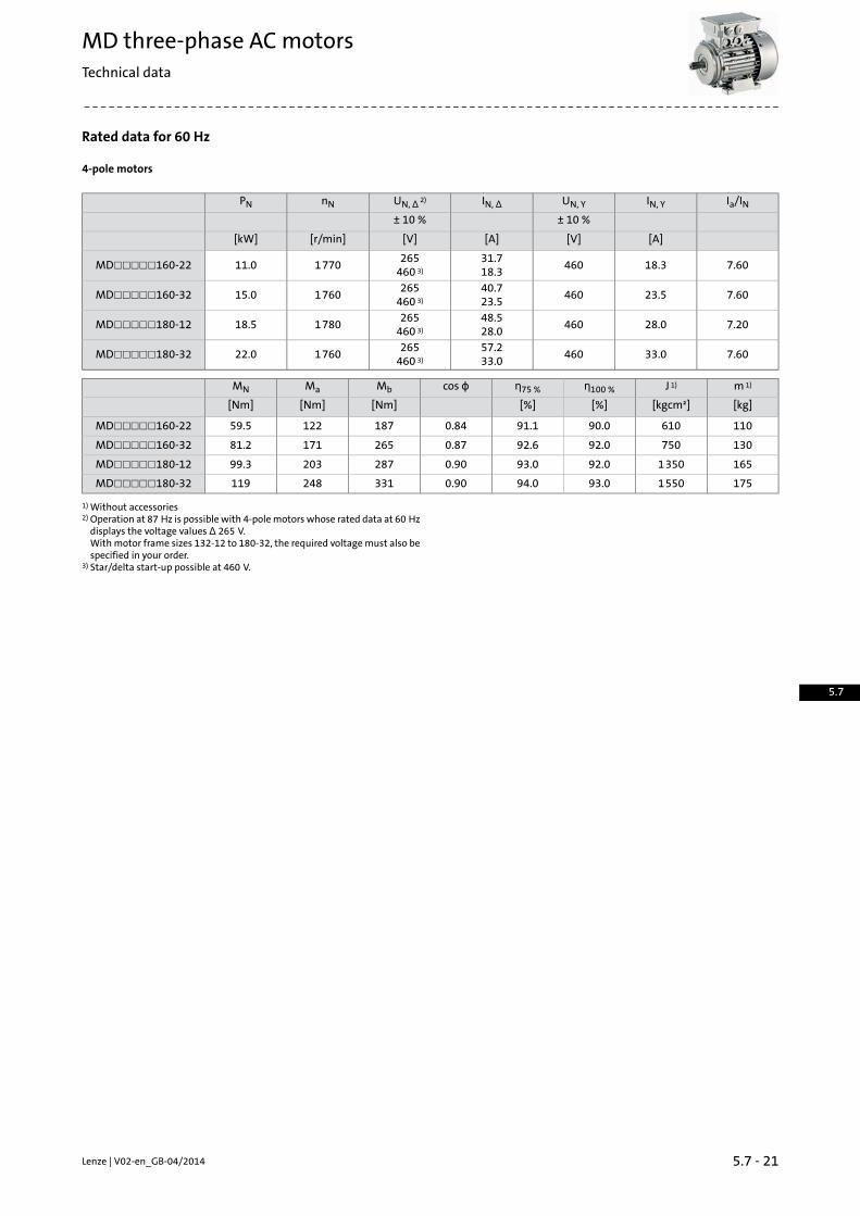
Rated data for 60 Hz
4-pole motors
Ia/ININ, YUN, YIN, ΔUN, Δ 2)nNPN± 10 %± 10 %
[A][V][A][V][r/min][kW]
7.6018.346031.718.3
265460 3)
177011.0MD☐☐☐☐☐160-22
7.6023.546040.723.5
265460 3)
176015.0MD☐☐☐☐☐160-32
7.2028.046048.528.0
265460 3)
178018.5MD☐☐☐☐☐180-12
7.6033.046057.233.0
265460 3)
176022.0MD☐☐☐☐☐180-32
m 1)J 1)η100 %η75 %cos ϕMbMaMN
[kg][kgcm²][%][%][Nm][Nm][Nm]
11061090.091.10.8418712259.5MD☐☐☐☐☐160-2213075092.092.60.8726517181.2MD☐☐☐☐☐160-32165135092.093.00.9028720399.3MD☐☐☐☐☐180-12175155093.094.00.90331248119MD☐☐☐☐☐180-32
Without accessories1)
Operation at 87 Hz is possible with 4-polemotors whose rated data at 60 Hzdisplays the voltage values Δ 265 V.
2)
Withmotor frame sizes 132-12 to 180-32, the required voltagemust also bespecified in your order.Star/delta start-up possible at 460 V.3)
5.7 - 21Lenze | V02-en_GB-04/2014
MD three-phase AC motorsTechnical data
5.7

Rated data for 87 Hz
4-pole motors
m 1)J 1)η100 %η75 %cos ϕIN, ΔUN, ΔMmaxMNnNPN± 10 %
[kg][kgcm²][%][%][A][V][Nm][Nm][r/min][kW]
4.103.3066.061.00.520.854003.200.8025350.21MD☐☐☐☐☐063-124.103.3071.068.00.651.004005.001.2624750.33MD☐☐☐☐☐063-324.403.7073.066.00.631.404007.001.7424800.45MD☐☐☐☐☐063-425.808.3068.066.00.741.304007.001.7424800.45MD☐☐☐☐☐071-125.8010.778.076.00.721.6040010.02.5125200.66MD☐☐☐☐☐071-326.4012.880.079.00.742.4040015.03.7425151.00MD☐☐☐☐☐071-4210.016.972.072.00.782.5040015.03.8025001.00MD☐☐☐☐☐080-1211.026.077.075.00.803.3040020.05.1025201.35MD☐☐☐☐☐080-3211.026.082.081.00.804.8040030.07.5025002.00MD☐☐☐☐☐080-4212.023.277.077.00.784.8040030.07.5625002.00MD☐☐☐☐☐090-1215.028.485.083.00.736.7040040.010.125202.70MD☐☐☐☐☐090-3224.061.088.087.00.719.2040060.014.625503.90MD☐☐☐☐☐100-1224.061.088.087.00.7312.540080.020.525405.40MD☐☐☐☐☐100-3231.010788.087.00.7116.140010526.325607.10MD☐☐☐☐☐112-2256.018890.090.00.7420.140014536.225609.70MD☐☐☐☐☐132-1266.033690.090.00.7528.640020049.2256513.2MD☐☐☐☐☐132-2211061090.091.70.8536.540028071.9256519.3MD☐☐☐☐☐160-2213075092.091.90.8648.440039098.1256526.4MD☐☐☐☐☐160-32165135092.092.80.8957.8400480120257532.4MD☐☐☐☐☐180-12175155092.092.80.8967.4400572144256038.7MD☐☐☐☐☐180-32
Without accessories1)
Lenze | V02-en_GB-04/20145.7 - 22
MD three-phase AC motorsTechnical data
5.7

5.7 - 23Lenze | V02-en_GB-04/2014
MD three-phase AC motorsTechnical data
5.7

Dimensions, self-ventilated (4-pole)
Design B3
Motortype
MDEMABRMDEMAXX
n2m1xg1gkn2m1xg1gk
[mm][mm][mm][mm][mm][mm][mm][mm][mm][mm][mm][mm]
10313617109123271
10313617109123215063
2411813929724118139246071
121152
25132154345
121152
25132156272080
2913717637329137176311090
3614719446336147194382100
3815821847938158218392112
1251945118725857612519451187258497132
12722665210313
703 1)
12722665210310
598 1)
160747 2)642 2)
7523035178475230348671180
160-221)
160-322)
Lenze | V02-en_GB-04/20145.7 - 24
MD three-phase AC motorsTechnical data
5.7

Dimensions, self-ventilated (4-pole)
Design B3
Motortype
MDEMABSMDEMARSMDEMABIMDEMAIGMDEMABAMDEMAAG
n2m1xg1gkn2m1xg1gk
[mm][mm][mm][mm][mm][mm][mm][mm][mm][mm][mm][mm]
10313617109123318103136
17109123255063
125194
1313313934124118139297071
24142156383
121152
25132156369080
2814717641029137178392090
3515819448336147196463100
3716821851238158220472112
5118725862112519451187261599132
12722665210313
789 1)
12722665210313
681 1)
160833 2)725 2)
7523035186375230351750180
utl2l1ld2dd
k6j6
[mm][mm][mm][mm][mm][mm][mm][mm]
4.012.5163.523M411063
5.016.0224.0
30M514071
6.021.53240M619080
8.0
27.040
5.0
50M824090
31.05060M1028100
112
10.041.07080M1238132
12.045.0100110M16
42160
14.051.548180
s5c5he5b5i4b7[mm][mm][mm][mm][mm][mm][mm]
7.010631208040100063
11711349045112071
10.01380154
10050125080
9017456140090
12.0
15100194140
63160100
1411222370190112
1813226017889216132
14.5
22160305210 1)
108254160254 2)
23180350241 3)
121279180279 4)
160-221)
160-322)
180-123)
180-324)
5.7 - 25Lenze | V02-en_GB-04/2014
MD three-phase AC motorsTechnical data
5.7

Dimensions, self-ventilated (4-pole)
Design B5
Motortype
MDEMABRMDEMAXX
n2m1xg1gkn2m1xg1gk
[mm][mm][mm][mm][mm][mm][mm][mm][mm][mm][mm][mm]
10313617109123271
10313617109123215063
2411813929724118139246071
121152
25132154345
121152
25132156272080
2913717637329137176311090
3614719446336147194382100
3815821847938158218392112
1251945118725857612519451187258497132
12722665210313
703 1)
12722665210310
598 1)
160747 2)642 2)
7523035178475230348671180
160-221)
160-322)
Lenze | V02-en_GB-04/20145.7 - 26
MD three-phase AC motorsTechnical data
5.7

Dimensions, self-ventilated (4-pole)
Design B5
Motortype
MDEMABSMDEMARSMDEMABIMDEMAIGMDEMABAMDEMAAG
n2m1xg1gkn2m1xg1gk
[mm][mm][mm][mm][mm][mm][mm][mm][mm][mm][mm][mm]
10313617109123318103136
17109123255063
125194
1313313934124118139297071
24142156383
121152
25132156369080
2814717641029137178392090
3515819448336147196463100
3716821851238158220472112
5118725862112519451187261599132
12722665210313
789 1)
12722665210313
681 1)
160833 2)725 2)
7523035186375230351750180
160-221)
160-322)
utl2l1ld2dd
k6j6
[mm][mm][mm][mm][mm][mm][mm][mm]
4.012.5163.523M411063
5.016.0224.0
30M514071
6.021.53240M619080
8.0
27.040
5.0
50M824090
31.05060M1028100
112
10.041.07080M1238132
12.045.0100110M16
42160
14.051.548180
Flange size
i2s2f2e2c2b2a2-0.6 ... 0.5j6
[mm][mm][mm][mm][mm][mm][mm]
23.010.0
3.011510
95140FF115063
30.0
3.5
130110160FF130071
40.012.016511130200FF165
080
50.0090
60.014.54.0
21515180250FF215100
112
80.026520230300FF265132
11018.55.030013250350FF300160
180
5.7 - 27Lenze | V02-en_GB-04/2014
MD three-phase AC motorsTechnical data
5.7

Dimensions, self-ventilated (4-pole)
Design B14
Motortype
MDEMABRMDEMAXX
n2m1xg1gkn2m1xg1gk
[mm][mm][mm][mm][mm][mm][mm][mm][mm][mm][mm][mm]
10313617109123271
10313617109123215063
2411813929724118139246071
121152
25132154345
121152
25132156272080
2913717637329137176311090
3614719446336147194382100
3815821847938158218392112
Lenze | V02-en_GB-04/20145.7 - 28
MD three-phase AC motorsTechnical data
5.7

Dimensions, self-ventilated (4-pole)
Design B14
Motortype
MDEMABSMDEMARSMDEMABIMDEMAIGMDEMABAMDEMAAG
n2m1xg1gkn2m1xg1gk
[mm][mm][mm][mm][mm][mm][mm][mm][mm][mm][mm][mm]
10313617109123318103136
17109123255063
125194
1313313934124118139297071
24142156383
121152
25132156369080
2814717641029137178392090
3515819448336147196463100
3716821851238158220472112
utl2l1ld2dd
k6j6
[mm][mm][mm][mm][mm][mm][mm][mm]
4.012.5163.523M411063
5.016.0224.0
30M514071
6.021.53240M619080
8.0
27.040
5.0
50M824090
31.05060M1028100
112
Flange size
i2s2f2e2b2a2-0.6 ... 0.5j6
[mm][mm][mm][mm][mm][mm]
23.0M5x102.5
756090FT75063
30.0M6x108570105FT85071
40.0M6x123.010080120FT100
080M8x143.5130110160FT130
50.0M8x163.011595140FT115
090
3.5130110160FT13060.0
M8x14100
M8x16112
5.7 - 29Lenze | V02-en_GB-04/2014
MD three-phase AC motorsTechnical data
5.7

Dimensions, forced ventilated (4-pole)
Design B3
Motortype
MDFMABRMDFMAXX
m2k4g3n2m1xg1gkm2k4g3n2m1xg1gk
[mm][mm][mm][mm][mm][mm][mm][mm][mm][mm][mm][mm][mm][mm][mm][mm][mm][mm]
9512115
10313617109123385
9512115
10313617109123345063
1222411813841012224118138373071
9613132
121152
251321564559613132
121152
25132156400080
9522
14129137176487
9522
14129137176434090
1503614719455215036147194491100
1623815821857516238158218494112
32182125194511872576983218212519451187257612132
963120912722665210309
777 1)
963120912722665210309
747 1)
160821 2)791 2)
7523034888675230348820180
160-221)
160-322)
Lenze | V02-en_GB-04/20145.7 - 30
MD three-phase AC motorsTechnical data
5.7

Dimensions, forced ventilated (4-pole)
Design B3
Motortype
MDFMABSMDFMARSMDFMABIMDFMAIGMDFMABAMDFMAAG
m2k4g3n2m1xg1gkm2k4g3n2m1xg1gk
[mm][mm][mm][mm][mm][mm][mm][mm][mm][mm][mm][mm][mm][mm][mm][mm][mm][mm]
951211510313617109123385
9512115
10313617109123345063
122
125194
1313313841012224118138373071
9613132241421564559613132
121152
25132156400080
9522
14128147176487
9522
14129137176434090
1503515819455215036147194491100
1623716821857516238158218575112
32182511872576983218212519451187257698132
963120912722665210309
835 1)
963120912722665210309
822 1)
160877 2)866 2)
7523034894675230348886180
utl2l1ld2dd
k6j6
[mm][mm][mm][mm][mm][mm][mm][mm]
4.012.5163.523M411063
5.016.0224.0
30M514071
6.021.53240M619080
8.0
27.040
5.0
50M824090
31.05060M1028100
112
10.041.07080M1238132
12.045.0100110M16
42160
14.051.548180
s5c5he5b5i4b7[mm][mm][mm][mm][mm][mm][mm]
7.010631208040100063
11711349045112071
10.01380154
10050125080
9017456140090
12.0
15100194140
63160100
1411222370190112
1813226017889216132
14.5
22160305210 1)
108254160254 2)
23180350241 3)
121279180279 4)
160-221)
160-322)
180-123)
180-324)
5.7 - 31Lenze | V02-en_GB-04/2014
MD three-phase AC motorsTechnical data
5.7

Dimensions, forced ventilated (4-pole)
Design B5
Motortype
MDFMABRMDFMAXX
m2k4g3n2m1xg1gkm2k4g3n2m1xg1gk
[mm][mm][mm][mm][mm][mm][mm][mm][mm][mm][mm][mm][mm][mm][mm][mm][mm][mm]
9512115
10313617109123385
9512115
10313617109123345063
1222411813841012224118138373071
9613132
121152
251321564559613132
121152
25132156400080
9522
14129137176487
9522
14129137176434090
1503614719455215036147194491100
1623815821857516238158218494112
32182125194511872576983218212519451187257612132
963120912722665210309
777 1)
963120912722665210309
747 1)
160821 2)791 2)
7523034888675230348820180
160-221)
160-322)
Lenze | V02-en_GB-04/20145.7 - 32
MD three-phase AC motorsTechnical data
5.7

Dimensions, forced ventilated (4-pole)
Design B5
Motortype
MDFMABSMDFMARSMDFMABIMDFMAIGMDFMABAMDFMAAG
m2k4g3n2m1xg1gkm2k4g3n2m1xg1gk
[mm][mm][mm][mm][mm][mm][mm][mm][mm][mm][mm][mm][mm][mm][mm][mm][mm][mm]
951211510313617109123385
9512115
10313617109123345063
122
125194
1313313841012224118138373071
9613132241421564559613132
121152
25132156400080
9522
14128147176487
9522
14129137176434090
1503515819455215036147194491100
1623716821857516238158218575112
32182511872576983218212519451187257698132
963120912722665210309
835 1)
963120912722665210309
822 1)
160877 2)866 2)
7523034894675230348886180
160-221)
160-322)
utl2l1ld2dd
k6j6
[mm][mm][mm][mm][mm][mm][mm][mm]
4.012.5163.523M411063
5.016.0224.0
30M514071
6.021.53240M619080
8.0
27.040
5.0
50M824090
31.05060M1028100
112
10.041.07080M1238132
12.045.0100110M16
42160
14.051.548180
Flange size
i2s2f2e2c2b2a2-0.6 ... 0.5j6
[mm][mm][mm][mm][mm][mm][mm]
23.010.0
3.011510
95140FF115063
30.0
3.5
130110160FF130071
40.012.016511130200FF165
080
50.0090
60.014.54.0
21515180250FF215100
112
80.026520230300FF265132
11018.55.030013250350FF300160
180
5.7 - 33Lenze | V02-en_GB-04/2014
MD three-phase AC motorsTechnical data
5.7

Dimensions, forced ventilated (4-pole)
Design B14
Motortype
MDFMABRMDFMAXX
m2k4g3n2m1xg1gkm2k4g3n2m1xg1gk
[mm][mm][mm][mm][mm][mm][mm][mm][mm][mm][mm][mm][mm][mm][mm][mm][mm][mm]
9512115
10313617109123385
9512115
10313617109123345063
1222411813841012224118138373071
9613132
121152
251321564559613132
121152
25132156400080
9522
14129137176487
9522
14129137176434090
1503614719455215036147194491100
1623815821857516238158218494112
Lenze | V02-en_GB-04/20145.7 - 34
MD three-phase AC motorsTechnical data
5.7

Dimensions, forced ventilated (4-pole)
Design B14
Motortype
MDFMABSMDFMARSMDFMABIMDFMAIGMDFMABAMDFMAAG
m2k4g3n2m1xg1gkm2k4g3n2m1xg1gk
[mm][mm][mm][mm][mm][mm][mm][mm][mm][mm][mm][mm][mm][mm][mm][mm][mm][mm]
951211510313617109123385
9512115
10313617109123345063
122
125194
1313313841012224118138373071
9613132241421564559613132
121152
25132156400080
9522
14128147176487
9522
14129137176434090
1503515819455215036147194491100
1623716821857516238158218575112
utl2l1ld2dd
k6j6
[mm][mm][mm][mm][mm][mm][mm][mm]
4.012.5163.523M411063
5.016.0224.0
30M514071
6.021.53240M619080
8.0
27.040
5.0
50M824090
31.05060M1028100
112
Flange size
i2s2f2e2b2a2-0.6 ... 0.5j6
[mm][mm][mm][mm][mm][mm]
23.0M5x102.5
756090FT75063
30.0M6x108570105FT85071
40.0M6x123.010080120FT100
080M8x143.5130110160FT130
50.0M8x163.011595140FT115
090
3.5130110160FT13060.0
M8x14100
M8x16112
5.7 - 35Lenze | V02-en_GB-04/2014
MD three-phase AC motorsTechnical data
5.7

Dimensions, 8400 motec inverter
Rated frequency 50/60 Hz
Product key
InverterMotor
x50Hzn2, 50Hzm1, 50Hzg1, 50Hz[mm][mm][mm][mm]
29.5
161241
163E84DVB☐3714S☐☐☐2☐MD☐☐☐☐☐071-32
E84DVB☐5514S☐☐☐2☐MD☐☐☐☐☐071-42
32.5172
MD☐☐☐☐☐080-12E84DVB☐7514S☐☐☐2☐MD☐☐☐☐☐080-32
E84DVB☐1124S☐☐☐2☐MD☐☐☐☐☐080-42
36.2177MD☐☐☐☐☐090-12
E84DVB☐1524S☐☐☐2☐MD☐☐☐☐☐090-32
42.4176260217E84DVB☐2224S☐☐☐2☐MD☐☐☐☐☐100-12E84DVB☐3024S☐☐☐2☐MD☐☐☐☐☐100-32
32.0
195325
282E84DVB☐4024S☐☐☐2☐MD☐☐☐☐☐112-22
47.5301E84DVB☐5524S☐☐☐2☐MD☐☐☐☐☐132-12E84DVB☐7524S☐☐☐2☐MD☐☐☐☐☐132-22
Lenze | V02-en_GB-04/20145.7 - 36
MD three-phase AC motorsTechnical data
5.7

Dimensions, 8400 motec inverter
Rated frequency 87 Hz
Product key
InverterMotor
x87Hzn2, 87Hzm1, 87Hzg1, 87Hz[mm][mm][mm][mm]
23.5
161241
154E84DVB☐3714S☐☐☐2☐MD☐☐☐☐☐063-32
E84DVB☐5514S☐☐☐2☐MD☐☐☐☐☐063-42
29.5163
MD☐☐☐☐☐071-12E84DVB☐7514S☐☐☐2☐MD☐☐☐☐☐071-32
E84DVB☐1124S☐☐☐2☐MD☐☐☐☐☐071-42
32.5172MD☐☐☐☐☐080-12
E84DVB☐1524S☐☐☐2☐MD☐☐☐☐☐080-3231.5
176260
201E84DVB☐2224S☐☐☐2☐
MD☐☐☐☐☐080-42
35.2206MD☐☐☐☐☐090-12
E84DVB☐3024S☐☐☐2☐MD☐☐☐☐☐090-32
29.9195325
272E84DVB☐4024S☐☐☐2☐MD☐☐☐☐☐100-12E84DVB☐5524S☐☐☐2☐MD☐☐☐☐☐100-32
32.0282E84DVB☐7524S☐☐☐2☐MD☐☐☐☐☐112-22
5.7 - 37Lenze | V02-en_GB-04/2014
MD three-phase AC motorsTechnical data
5.7

Lenze | V02-en_GB-04/20145.7 - 38
MD three-phase AC motorsTechnical data
5.7

Spring-applied brakes
Three-phaseACmotors canbe fittedwith a spring-appliedbrake. Thisis activated after the supply voltage is switched off (closed-circuitprinciple). For optimumadjustment of the brakemotor to the applic-ation, a range of braking torques and control modes is available forevery motor frame size. For applications with very high operatingfrequencies the brake is also available in a LongLife version, with re-inforced mechanical brake components.
Features
ControlVersions• DC supply• Standard
- 1 x 10⁶ repeating switching cycles • AC supply via rectifier in the terminal box- 1 x 10⁶ reversing switching cycles
Enclosure• LongLife- 10 x 106 repeating switching cycles • Without manual release IP55- 15 x 106 reversing switching cycles • With manual release IP54
Friction lining• Non-asbestos, low wearing
Options• Manual release• UL/CSA approval• Noise-reduced
Assignment of 4-pole motors and brakes
Design
LongLifeStandard
Rated torqueSizeRated torqueSizeMotor frame size
BrakeBrake
MkMk
[Nm][Nm]
4.00062.504.00
0606
063-02063-12063-22063-32063-42
4.003.50
0608
2.504.00
0606
071-12071-32
3.5008
4.003.50
0608
2.504.00
0606
071-428.0008
3.50088.0008
8.007.00
0810
3.508.00
0808
080-12080-32
7.0010
8.007.00
0810
3.508.00
0808
080-4216.010
7.001016.010
5.7 - 39Lenze | V02-en_GB-04/2014
MD three-phase AC motorsAccessories
5.7

Spring-applied brakes
Assignment of 4-pole motors and brakes
Design
LongLifeStandard
Rated torqueSizeRated torqueSizeMotor frame size
BrakeBrake
MkMk
[Nm][Nm]
8.007.00
0810
3.508.00
0808
090-12090-32
16.0107.001016.01023.010
16.014.0
1012
7.0016.0
1010
100-12
32.012
14.01232.0127.0016.0
1010
100-32 14.01232.01246.01214.032.0
1212112-22
112-32 35.01460.01435.060.0
1414
132-1260.01680.01635.060.0
1414
132-22132-32
60.01680.0161001660.080.0
1616
160-2280.0181501880.0150
1818160-32
2001880.0150
1818
180-12145202602080.0150
1818
180-32 14520260203152080.0150
1818
180-4214520260203152040020
Lenze | V02-en_GB-04/20145.7 - 40
MD three-phase AC motorsAccessories
5.7

Spring-applied brakes
Direct connection without rectifier
If the brake is activated directly without a rectifier, a freewheelingdiode or a spark suppressor is required to protect against inductionpeaks.• Supply voltagesDC 24 VDC 180 VDC 205 V
Connection via mains voltage with brake rectifier
If the brake is not directly supplied with DC voltage, a rectifier is re-quired. This is included in the scope of supply and is located in theterminal box of the motor. The rectifier converts the AC voltage ofthe connection intoDC voltage. The following rectifiers are available:
Half-wave rectifier, 6-pole• Ratio of supply voltage to brake coil voltage = 2.22• Approved by UL/CSA• Supply voltagesAC 230 VAC 400 VAC 460 V
Bridge rectifier, 6-pole• Ratio of supply voltage to brake coil voltage = 1.11• Supply voltageAC 230 V
Bridge/half-wave rectifier, 6-pole• Ratio of supply voltage to brake coil voltageup to overexcitation time = 1.11beyond overexcitation time = 2.22
Supply voltages:• AC 230 V• AC 400 V
5.7 - 41Lenze | V02-en_GB-04/2014
MD three-phase AC motorsAccessories
5.7

Spring-applied brakes
Connection via mains voltage with brake rectifier
Bridge/half-wave rectifier, 6-pole• Ratio of supply voltage to brake coil voltageup to overexcitation time = 1.11beyond overexcitation time = 2.22
Supply voltages:• AC 230 V• AC 400 V
During the switching operation the bridge/half-wave rectifier func-tions as a bridge rectifier for the overexcitation time tü and then asa half-wave rectifier. This combination optimises the performanceof the brake – depending on the assignment of brake coil voltage andsupply voltage:
• Holding current reduction (cold brake)• Short-time overexcitation of the brake coilBy reducing the holding current, the bridge/half-wave rectifier isable to reduce the power input to the open brake. As the brakeheats up less, this type of activation is known as "cold brake".
Activating the brake coil for the overexcitation time tüwith twicethe rated voltage allows the disengagement time to be reduced.The brake opens more quickly and wear on the friction lining isreduced.These features make this activation version particularly suitablefor lifting applications. It is therefore only available in combinationwith a brake with increased braking torque.
Lenze | V02-en_GB-04/20145.7 - 42
MD three-phase AC motorsAccessories
5.7

Spring-applied brakes
Permissible friction energy
Q =Switching energy per switching cycleSh =Operating frequencyBrake size = 06 to 25
5.7 - 43Lenze | V02-en_GB-04/2014
MD three-phase AC motorsAccessories
5.7

Spring-applied brakes
Rated data with reduced braking torque
ƒ Please enquire for braking torques andmaximumswitchingworkvalues not listed here.
Size
252018161412100806Power input
0.110.100.0850.0550.0500.0400.0300.0250.020[kW]PinBraking torque
26514580.060.035.014.07.003.502.50[Nm]MB100
20311565.050.030.012.06.103.102.30[Nm]MB1000
19911263.048.029.012.06.003.102.30[Nm]MB1200
193 1)109 1)61.047.028.011.05.803.002.20[Nm]MB1500
60.0 1)46.028.011.05.702.902.10[Nm]MB1800
43.0 1)26.0 1)10.05.302.802.00[Nm]MB3000
10.0 1)5.202.702.00[Nm]MB3600Maximum switching energy
12080.060.036.030.024.012.07.503.00[KJ]QE100
12080.060.036.030.024.012.07.503.00[KJ]QE1000
12080.060.036.030.024.012.07.503.00[KJ]QE1200
36.0 1)24.0 1)60.036.030.024.012.07.503.00[KJ]QE1500
36.0 1)36.030.024.012.07.503.00[KJ]QE1800
11.0 1)18.0 1)24.012.07.503.00[KJ]QE3000
7.00 1)12.07.503.00[KJ]QE3600Transition operating frequency
15.019.020.027.028.030.040.050.079.0[1/h]ShüMoment of inertia
20.07.302.901.500.630.450.200.0610.015[kgcm²]JMass
31.019.512.68.705.804.202.601.500.90[kg]m
In the regionof the load limit the value for friction energyQBW canbe reducedto 40 %.
1)
Lenze | V02-en_GB-04/20145.7 - 44
MD three-phase AC motorsAccessories
5.7

Spring-applied brakes
Rated data with reduced braking torque
ƒ Activation via half-wave or bridge rectifier
Size
252018161412100806Friction energy
352223221542966761706264210113[MJ]QBWDelay time
26447.032.053.037.021.020.014.011.0[ms]t11EngagingRise time
12010020.030.022.019.017.010.013.0[ms]t12Braking torqueEngagement time
38414752.083.059.040.037.024.0[ms]t1Disengagement time
26920723016914865.057.037.035.0[ms]t2
ƒ Activation via bridge/half-wave rectifier
Design
Holding current reduction (cold brake)Size
252018161412100806Friction energy
352223221542966761706264210113[MJ]QBWOverexcitation time
1300300[ms]tüMin. rest time
3900900[ms]tDelay time
30412683.011461.049.035.022.012.0[ms]t11EngagingRise time
13826952.065.037.045.030.016.014.0[ms]t12Braking torqueEngagement time
44339513418097.093.066.038.026.0[ms]t1Disengagement time
26920723016914865.057.037.035.0[ms]t2
ƒ The brake response and application times are guide values. Theengagement time is 10 times longer with AC-side switching.With themaximumair gap thedisengagement time t2–depend-ing on the brake and control – is up to 4 times longer than thedisengagement time with the rated air gap.
5.7 - 45Lenze | V02-en_GB-04/2014
MD three-phase AC motorsAccessories
5.7

Spring-applied brakes
Rated data with standard braking torque
ƒ Please enquire for braking torques andmaximumswitchingworkvalues not listed here.
Size
252018161412100806Power input
0.110.100.0850.0550.0500.0400.0300.0250.020[kW]PinBraking torque
40026015080.060.032.016.08.004.00[Nm]MB100
30720612166.051.027.014.07.203.70[Nm]MB1000
30020111865.050.027.014.07.003.60[Nm]MB1200
291 1)195 1)11563.048.026.013.06.803.50[Nm]MB1500
112 1)61.047.026.013.06.703.40[Nm]MB1800
57.0 1)44.0 1)24.012.06.303.20[Nm]MB3000
23.0 1)12.06.103.20[Nm]MB3600Maximum switching energy
12080.060.036.030.024.012.07.503.00[KJ]QE100
12080.060.036.030.024.012.07.503.00[KJ]QE1000
12080.060.036.030.024.012.07.503.00[KJ]QE1200
36.0 1)24.0 1)60.036.030.024.012.07.503.00[KJ]QE1500
36.0 1)36.030.024.012.07.503.00[KJ]QE1800
11.0 1)18.0 1)24.012.07.503.00[KJ]QE3000
7.00 1)12.07.503.00[KJ]QE3600Transition operating frequency
15.019.020.027.028.030.040.050.079.0[1/h]ShüMoment of inertia
20.07.302.901.500.630.450.200.0610.015[kgcm²]JMass
31.019.512.68.705.804.202.601.500.90[kg]m
In the regionof the load limit the value for friction energyQBW canbe reducedto 40 %.
1)
Lenze | V02-en_GB-04/20145.7 - 46
MD three-phase AC motorsAccessories
5.7
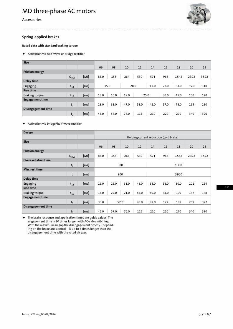
Spring-applied brakes
Rated data with standard braking torque
ƒ Activation via half-wave or bridge rectifier
Size
252018161412100806Friction energy
35222322154296657153026415885.0[MJ]QBWDelay time
11065.033.027.017.028.015.0[ms]t11EngagingRise time
12010045.030.025.019.016.013.0[ms]t12Braking torqueEngagement time
23016578.057.042.053.047.031.028.0[ms]t1Disengagement time
39034027022021011576.057.045.0[ms]t2
ƒ Activation via bridge/half-wave rectifier
Design
Holding current reduction (cold brake)Size
252018161412100806Friction energy
35222322154296657153026415885.0[MJ]QBWOverexcitation time
1300300[ms]tüMin. rest time
3900900[ms]tDelay time
15410280.058.033.048.031.025.016.0[ms]t11EngagingRise time
16815710964.049.043.021.027.014.0[ms]t12Braking torqueEngagement time
32225918912282.090.052.030.0[ms]t1Disengagement time
39034027022021011576.057.045.0[ms]t2
ƒ The brake response and application times are guide values. Theengagement time is 10 times longer with AC-side switching.With themaximumair gap thedisengagement time t2–depend-ing on the brake and control – is up to 4 times longer than thedisengagement time with the rated air gap.
5.7 - 47Lenze | V02-en_GB-04/2014
MD three-phase AC motorsAccessories
5.7

Spring-applied brakes
Rated data with increased braking torque
ƒ Please enquire for braking torques andmaximumswitchingworkvalues not listed here.
Size
25252020181616141210Power input
0.110.110.100.100.0850.0550.0550.0500.0400.030[kW]PinBraking torque
60049040031520012510075.046.023.0[Nm]MB100
46137631724916210383.064.039.020.0[Nm]MB1000
44936730924415810181.062.039.020.0[Nm]MB1200
436 1)356 1)300 1)237 1)15398.078.060.038.019.0[Nm]MB1500
150 1)96.077.059.037.019.0[Nm]MB1800
89.0 1)71.0 1)55.0 1)34.017.0[Nm]MB3000
33.0 1)17.0[Nm]MB3600Maximum switching energy
12012080.080.060.036.036.030.024.012.0[KJ]QE100
12012080.080.060.036.036.030.024.012.0[KJ]QE1000
12012080.080.060.036.036.030.024.012.0[KJ]QE1200
36.0 1)36.0 1)24.0 1)24.0 1)60.036.036.030.024.012.0[KJ]QE1500
36.0 1)36.036.030.024.012.0[KJ]QE1800
11.0 1)11.0 1)18.0 1)24.012.0[KJ]QE3000
7.00 1)12.0[KJ]QE3600Transition operating frequency
15.015.019.019.020.027.027.028.030.040.0[1/h]ShüMoment of inertia
20.020.07.307.302.901.501.500.630.450.20[kgcm²]JMass
31.031.019.519.512.68.708.705.804.202.60[kg]m
In the regionof the load limit the value for friction energyQBW canbe reducedto 40 %.
1)
ƒ Activation via half-wave or bridge rectifier
Size
25201816141210Friction energy
140924655801596578241563253353198[MJ]QBWDelay time
38.077.017.046.024.017.022.011.016.010.0[ms]t11EngagingRise time
12010045.030.025.019.0[ms]t12Braking torqueEngagement time
15819711714669.047.052.036.041.029.0[ms]t1Disengagement time
532451470378356435297308193109[ms]t2
Lenze | V02-en_GB-04/20145.7 - 48
MD three-phase AC motorsAccessories
5.7

Spring-applied brakes
Rated data with increased braking torque
ƒ Activation via bridge/half-wave rectifier
Design
Holding current reduction (cold brake)Size
25201816141210Friction energy
140924655801596578241563253353198[MJ]QBWOverexcitation time
1300300[ms]tüMin. rest time
3900900[ms]tDelay time
85.012317.069.060.021.041.017.027.024.0[ms]t11EngagingRise time
27019010014811337.055.037.043.044.0[ms]t12Braking torqueEngagement time
35531333421717357.097.054.070.068.0[ms]t1Disengagement time
532451470378356435297308193109[ms]t2
Design
Over-excitationSize
25201816141210Friction energy
352223221542966761706264[MJ]QBWOverexcitation time
1300300[ms]tüMin. rest time
3900900[ms]tDelay time
13517155.010386.046.070.031.054.029.0[ms]t11EngagingRise time
43026631922216083.093.068.087.053.0[ms]t12Braking torqueEngagement time
56543737432524612916399.014182.0[ms]t1Disengagement time
20418416716015116814111781.053.0[ms]t2
ƒ The brake response and application times are guide values. Theengagement time is 10 times longer with AC-side switching.With themaximumair gap thedisengagement time t2–depend-ing on the brake and control – is up to 4 times longer than thedisengagement time with the rated air gap.
5.7 - 49Lenze | V02-en_GB-04/2014
MD three-phase AC motorsAccessories
5.7

Spring-applied brakes
Manual release lever
Brake
d12h5Δ kk5[mm][mm][mm][mm]
13.01072917806063
13.013.0
107116
2927
205206
0608
071
13.013.0
116132
2728
224239
0810
080
13.013.0
116132
2728
238251
0810
090
13.013.0
132161
2837
305307
1012
100
13.024.0
161195
3741
320323
1214
112
24.024.0
195240
4155
400406
1416
132
24.024.0
240279
5559
505509
1618
160
24.024.0
279319
5974
540546
1820
180
The following combinations with manual release lever and motorconnection in the same position are not possible:• HAN connector with connection in position 1• Inverter motec• Terminal box of motor sizes 071, 080, 090 for brake and retracting(M☐☐MA BR/BS/BA/BI)
Lenze | V02-en_GB-04/20145.7 - 50
MD three-phase AC motorsAccessories
5.7
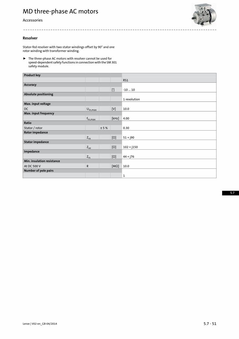
Resolver
Stator-fed resolver with two stator windings offset by 90° and onerotor winding with transformer winding.
ƒ The three-phase AC motors with resolver cannot be used forspeed-dependent safety functions in connectionwith the SM301safety module.
Product key
RS1Accuracy
-10 ... 10[']Absolute positioning
1 revolutionMax. input voltage
10.0[V]Uin,maxDCMax. input frequency
4.00[kHz]fin,maxRatio
0.30± 5 %Stator / rotorRotor impedance
51 + j90[Ω]ZroStator impedance
102 + j150[Ω]ZsoImpedance
44 + j76[Ω]ZrsMin. insulation resistance
10.0[MΩ]RAt DC 500 VNumber of pole pairs
1
5.7 - 51Lenze | V02-en_GB-04/2014
MD three-phase AC motorsAccessories
5.7

Incremental encoder andSinCosabsolute valueencoder
ƒ The three-phase ACmotorswith incremental encoders or SinCosabsolute value encoders cannot be used for speed-dependentsafety functions in connection with the SM 301 safety module.
Encoder type
SinCosabsolutevalue
TTL incrementalHTL incremental
Product key
AM1024-8V-H
IG2048-5V-T
IG1024-5V-T
IG512-5V-T
IG2048-24V-H
IG1024-24V-H
IG512-24V-H
IG128-24V-H
Encoder type
Multi-turn
Pulses
10242048102451220481024512128Output signals
1 VssTTLHTLInterfaces
HiperfaceA, B, N track and invertedA, B trackAbsolute revolutions
40960Accuracy
-0.8 ... 0.8-2 ... 2-22.5 ...22.5
[']
Min. input voltage
7.004.758.00[V]Uin,minDCMax. input voltage
12.05.2530.026.0[V]Uin,maxDCMax. current consumption
0.0800.150.040[A]ImaxLimit frequency
20030016030.0[kHz]fmaxInverter assignment
E84AVTCE84AVHCE84AVSCE94AE84AVHCECS
EVS93
Servo-InvertersInverters• Servo Drives 9400 (E94A)• Inverter Drives 8400 StateLine (E84AVSC)
• Inverter Drives 8400 HighLine (E84AVHC) • 9300 servo inverters (EVS93)• Servo Drives ECS• Inverter Drives 8400 TopLine (E84AVTC)
Lenze | V02-en_GB-04/20145.7 - 52
MD three-phase AC motorsAccessories
5.7

Blowers
ƒ The blower terminal box is available in positions 2, 3 or 5.
Rated data for 50 Hz
Connectionmethod
Number ofphases
Size
Motor
mImaxPmaxUmaxUmin
[kg][A][kW][V][V]
2.00
0.110.0272772301
063 0.120.028
303200Δ3
0.070525346Y
2.10
0.100.0272772301
071 0.110.031
303200Δ3
0.060525346Y
2.300.11
0.0292772301
0800.031
303200Δ3
0.060525346Y
2.70
0.290.0652772201
090 0.380.091
303200Δ3
0.22525346Y
3.00
0.280.0662772201
100 0.370.091
303200Δ3
0.22525346Y
3.10
0.280.0712772201
112 0.350.097
303200Δ3
0.20525346Y
4.20
0.400.0982772301
132 0.580.12
303200Δ3
0.33525346Y
6.20
0.97
0.25
2772301
160 0.87303200Δ3
0.50525346Y
8.00
0.972772301
180 0.87303200Δ3
0.50525346Y
5.7 - 53Lenze | V02-en_GB-04/2014
MD three-phase AC motorsAccessories
5.7

Blowers
Rated data for 50 Hz
Connectionmethod
Number ofphases
Size
Motor
mImaxPmaxUmaxUmin
[kg][A][kW][V][V]
8.00
0.97
0.25
2772301
200 0.87303200Δ
30.50525346Y
15.01.100.28400200Δ
2250.350.17525346Y
Rated data for 60 Hz
Connectionmethod
Number ofphases
Size
Motor
mImaxPmaxUmaxUmin
[kg][A][kW][V][V]
2.00
0.120.0322772301
063 0.100.028
332220Δ3
0.060575380Y
2.10
0.120.0332772301
071 0.100.029
332220Δ3
0.060575380Y
2.30
0.140.0372772301
080 0.100.034
332220Δ3
0.060575380Y
2.70
0.250.065277220
1
090 0.330.077
332Δ3
0.19575380Y
3.00
0.300.075277220
1
100 0.310.087
332Δ3
0.18575380Y
3.10
0.370.094277220
1
112 0.310.10
332Δ3
0.18575380Y
4.20
0.57
0.15
2772301
132 0.44332220Δ
3
0.25575380Y
6.200.93
0.36
332220Δ160
0.56575380Y
8.00
0.93332220Δ180
0.56575380Y
0.93332220Δ200
0.56575380Y
15.00.760.28400220Δ
2250.430.26575380Y
Lenze | V02-en_GB-04/20145.7 - 54
MD three-phase AC motorsAccessories
5.7

Temperature monitoring
ƒ The thermal sensors are integrated in the windings. The use ofan additional motor protection switch is recommended.
TKO thermal contacts
Max. input voltageMax. input currentMax. reset temperat-ure
Min. reset temperat-ure
Operating temperat-ure
Function
AC
Uin,maxIin,maxTmaxTminT
-5 ... 5
[V][A][°C][°C][°C]
2502.5013590.0150NC contact
PTC thermistor
StandardRated resistanceOperating temperat-ure
Function
140 °C-20 °C155 °C
RNRNRNT
-5 ... 5
[Ω][Ω][Ω][°C]
DIN 44080DIN VDE 0660 Part
30325030.0550150
Sudden change in res-istance
5.7 - 55Lenze | V02-en_GB-04/2014
MD three-phase AC motorsAccessories
5.7

Temperature monitoring
KTY temperature sensor
Max. input currentRated resistanceFunction
170 °C25 °C170 °C150 °C25 °C
Iin,maxIin,maxRNRNRN[A][A][Ω][Ω][Ω]
0.0020.010247122251000Continuous resistance changeKTY83-110
0.0020.01014821334603Continuous resistance changeKTY84-130
Variation of resistance
ƒ If the detector is supplied with a measured current of 1 mA, theabove relationship between the temperature and the resistanceapplies.
Lenze | V02-en_GB-04/20145.7 - 56
MD three-phase AC motorsAccessories
5.7

Terminal box
In the standard version, the motors are connected in the terminalbox. As an option, the motors are also available with the connectors
The three-phase ACmotors are designed for operation at a constantmains frequency and with an inverter.
described on the following pages as long as the permissible ratingsare not exceeded.
For 50 Hz operation, the motors are operated in Δconfiguration at230 V or in star configuration at 400 V.For inverter operation, thebase frequencyhas been specified as 87 Hzat a rated voltage of 400 V in Δconfiguration.
Connections
Motor type
M☐☐MABSM☐☐MAXXBuilt-on ac-cessories M☐☐MABIM☐☐MABR
M☐☐MABAM☐☐MARSM☐☐MAIGM☐☐MAAG
P6P4P3P2P1P6P4P3P2P1[mm][mm][mm][mm][mm][mm][mm][mm][mm][mm]
M16x1.5M16x1.5M20x1.5
M32x1.5M25x1.5
M16x1.5
M20x1.5M16x1.5063
071
M25x1.5M20x1.5
080
090
100
112
M16x1.5M20x1.5
M32x1.5M25x1.5132
M16x1.5M50x1.5M16x1.5M50x1.5
160
180
200
M12x1.5M50x1.5M63x1.5M12x1.5M12x1.5M50x1.5M63x1.5M12x1.5225 1)
The cable glands P1 to P4 are only arranged at the bottom.1)
5.7 - 57Lenze | V02-en_GB-04/2014
MD three-phase AC motorsAccessories
5.7

Plug connectors
ICN, HAN andM12 connectors (only for IG128-24V-H incrementalencoder) are available for the three-phase AC motors.
ICN connector
A connector is used for power, brake and temperature monitoring.The connections to the feedback systemand the blower each employa separate connector.
Connection for power, brake and temperature monitoring
The connectors can be rotated through 270° and are fitted with abayonet catch for SpeedTec connectors. As this connector is alsocompatiblewith conventional unionnuts, existingmating connectorscan continue to be used without difficulty. The motor connection isdetermined in the terminal boxandmust be checkedbefore commis-sioning.
ƒ ICN 6-pole
Pin assignment
MeaningDesignationContact
Brake +/ACBD1 / BA11
Brake /ACBD2 / BA22
PE conductorPEPE
Phase U powerU4
Phase V powerV5
Phase W powerW6
ƒ ICN 8-pole
Pin assignment
MeaningDesignationContact
Phase U powerU1
PE conductorPEPE
Phase V powerV3
Phase W powerW4
Thermal sensor: TKO/PTC/ +KTYTB1 / TP1 / R1A
Thermal sensor: TKO/PTC/-KTYTB2 / TP2 / R2B
Brake +/ACBD1 / BA1C
Brake /ACBD2 / BA2D
Lenze | V02-en_GB-04/20145.7 - 58
MD three-phase AC motorsAccessories
5.7

ICN connector
Feedback connection
All encoder systems (apart from IG128-24V-H) are also availablewithan ICN connector fixed to the motor terminal box for exceptionallyfast commissioning. The connectors are fitted with a bayonet fixing,which is also compatible with conventional union nuts. Existingmating connectors can therefore continue to be used without diffi-culty.
ƒ Resolver
Pin assignment
MeaningDesignationContact
Transformer windings+Ref1
-Ref2
Supply: Electronic nameplate+VCC ETS3
Cosine stator windings+COS4
-COS5
Sine stator windings+SIN6
-SIN7
Not assigned
8
9
10
KTY temperature sensor+KTY11
-KTY12
ƒ Hiperface incremental encoderandSinCosabsolutevalueencoder
Pin assignment
MeaningDesignationContact
Track B/+SINB1
Track A inverse/-COSA¯2
Track A/+COSA3
Supply ++UB4
MassGND5
Zero track inverse/-RS485Z¯6
Zero track/+RS485Z7
Not assigned8
Track B inverse/-SINB¯9
Not assigned10
KTY temperature sensor+KTY11
-KTY12
5.7 - 59Lenze | V02-en_GB-04/2014
MD three-phase AC motorsAccessories
5.7

ICN connector
Dimensions of the connectors on the terminal box
With the following motors, the feedback connection (B) is onlyavailable in position 3 or 5:
The following connector positions are possible:• power connection (A) in position 5 and feedback connection (B) inposition 3 • motor frame size 132 to 180
• power connection (A) in position 3 and feedback connection (B) inposition 5
Motor type
M☐☐MABRM☐☐MAXXM☐☐MABSM☐☐MARSM☐☐MABIM☐☐MAIGM☐☐MABAM☐☐MAAG
z1, maxx8x7n2m1xg1[mm][mm][mm][mm][mm][mm][mm]
431091610313617109063
24118071
4112523121152
25132080
29137090
36147100
38158112
711662712519451187132
65200127226
65210160
75230180
200
5132820435468348225
Lenze | V02-en_GB-04/20145.7 - 60
MD three-phase AC motorsAccessories
5.7

ICN connector
Blower connection
The blower is also optionally available with an ICN connector fixedto the terminal box of the blower for exceptionally fast commission-ing. The connectors are fitted with a bayonet fixing, which is alsocompatiblewith conventional union nuts. Existing counter plugs cantherefore continue to be used without difficulty.
ƒ Blower 1-ph
Pin assignment
MeaningDesignationContact
PE conductorPEPE
FanU11
U22
Not assigned
3
4
5
6
ƒ Blower 3-ph
Pin assignment
MeaningDesignationContact
PE conductorPEPE
Phase U powerU1
Not assigned2
Phase V powerV3
Not assigned4
5
Phase W powerW6
5.7 - 61Lenze | V02-en_GB-04/2014
MD three-phase AC motorsAccessories
5.7

ICN connector
Blower connection
ƒ The blower terminal box is available in positions 2, 3 or 5.ƒ In addition, the cover of the blower terminal box (including con-
nectors) can be rotated progressively through 90° if necessary.
Lenze | V02-en_GB-04/20145.7 - 62
MD three-phase AC motorsAccessories
5.7

M12 connector
IG128-24V-H incremental encoder connection
Asa standard this incremental encoder is equippedwith a connectioncable of about 0.5 m length and with a common industry standardM12 connector at its end.
Pin assignment
MeaningDesignationContact
Supply ++UB1
Track BB2
MassGND3
Track AA4
5.7 - 63Lenze | V02-en_GB-04/2014
MD three-phase AC motorsAccessories
5.7

HAN connector
10E
In the case of the rectangular HAN-10E connectors, all six ends of thethreewindingphases are takenout to thepower contacts. Themotorcircuit is therefore determined in the mating connector.
Pin assignment
MeaningContact
Terminal board: U11
Terminal board: V12
Terminal board: W13
Brake +/AC4
Brake -/AC5
Terminal board: W26
Terminal board: U27
Terminal board: V28
Thermal sensor: +KTY/PTC/TKO9
Thermal sensor: KTY/PTC/TKO10
Lenze | V02-en_GB-04/20145.7 - 64
MD three-phase AC motorsAccessories
5.7

HAN connector
Modular
The connector is available with two different power modules (16 Aor 40A), dependingon the ratedmotor current. Themotor connectionis determined in the terminal box and must be checked before com-missioning.
ƒ HANmodular 16 A
Pin assignment
MeaningContactModule
DummymoduleB
Thermal sensor: +KTY/PTC/TKO1
C
Brake +/AC2
Brake -/AC3
Rectifier: Switching contact4
5
Thermal sensor: KTY/PTC/TKO6
ƒ HANmodular 40 A
Pin assignment
MeaningContactModule
Terminal board: U11
A Terminal board: V12
Terminal board: W13
DummymoduleB
Thermal sensor: +KTY/PTC/TKO1
C
Brake +/AC2
Brake -/AC3
Rectifier: Switching contact4
5
Thermal sensor: KTY/PTC/TKO6
5.7 - 65Lenze | V02-en_GB-04/2014
MD three-phase AC motorsAccessories
5.7

HAN connector
ƒ The connection position for the connector is shown in position1. Positions 3 and 5 are also possible.
Motor type
M☐☐MAXXM☐☐MABR
x4x3x2n5m5g4[mm][mm][mm][mm][mm][mm]
1211
41102118
120063
1716129071
2618138080
3022143090
3729154100
3628164112
184847180120
233132 1)
4272248160
In the caseof theB5designmotors, it is not possible to connect the connectorat position 3 or 5.
1)
Lenze | V02-en_GB-04/20145.7 - 66
MD three-phase AC motorsAccessories
5.7
5.7 - 67Lenze | V02-en_GB-04/2014
MD three-phase AC motorsAccessories
5.7

Lenze | V02-en_GB-04/20145.7 - 68
MD three-phase AC motorsAccessories
5.7


Internet version
Lenze SEHans-Lenze-Straße 1D-31855 AerzenPhone: +49 (0)5154 82-0Telefax: +49 (0)5154 82 28 00
www.Lenze.com