Parallel Operation of Inverters and Active Power Filters in ...
Optimum control of Multilevel Inverters Using Artificial Neural Networks
M. Tarafdar Hagh, H. Taghizadeh and K. Razi
Department of Electrical and Computer Engineering, University of Tabriz, Tabriz, Iran E-mail: [email protected]
Abstract-Estimation of optimum switching angles for
multilevel converters so as to produce the required fundamental voltage while at the same time eliminate specified lower order harmonics through Artificial Neural Networks (ANNs) is presented. The proposed technique uses the best performance solutions (lowest THD solutions) as the training data set for proposed ANN system. This technique can be applied to multilevel inverters with any number of levels. As an example, in this paper estimation results of optimum switching angles are given for seven levels inverter to eliminate the 5th and 7th harmonics. After training the proposed ANN system, a large and memory-demanding look-up table replaced with trained neural network to generate the optimum switching angles with lowest THD for a given modulation index. The simulation results are presented in PSCAD/EMTDC software package to validate the accuracy of estimation results by proposed ANN system.
I. INTRODUCTION
Multilevel power conversion has been receiving special attention in the past few years for high voltage and high power applications due to their lower switching frequency, lower switching losses, high voltage rating and lower electromagnetic interfaces (EMI) than conventional two level inverters [1]-[3]. The output voltage waveform of multilevel inverters is synthesized by several sources of DC voltages so it can work as amplitude modulation and this fact makes the outputs of the inverter much cleaner. Numerous topologies and modulation strategies have been introduced and studied extensively for utility and drive applications in the recent literatures. In the family of multilevel inverters, topologies based on series-connected H-bridges are particularly attractive because of their modularity and simplicity of control [1], [2]. Moreover, to decrease the undesired harmonics and control the output voltage of inverter various modulation strategies such as Sinusoidal PWM (SPWM), Space-Vector PWM (SVPWM), Non-sinusoidal PWM and Selective Harmonic Elimination (SHE) have been suggested for multilevel inverters [4]-[7]. Among the mentioned techniques only SHE method is able to eliminate low order harmonics completely. In the SHE method, mathematical techniques such as iterative methods or mathematical theory of resultant can be applied to calculate the optimum switching angels such that lower order dominant harmonics are eliminated [3], [4].
The application of artificial neural networks (ANNs) is recently growing in the power electronics and drives areas. In the control of dc–ac inverters, ANNs have been used in the current control of inverters for ac motor drives [8], [9]. In literatures [9], [10] an application of ANNs for the harmonic
elimination of PWM inverters has been presented, where an ANN replaces a large and memory-demanding look-up table to generate the switching angles of a PWM inverter for a given modulation index.
A new application of artificial neural networks for the power electronics areas is proposed in [11], where an ANN is used as an alternative for the switching angles look-up table to generate the optimum switching angles of multilevel inverters. The advantages of this method are simple control circuit, controlling the magnitude of output voltage continuously versus modulation indexes and there is no need to any lookup table after training the ANN. However, by the proposed method in [11] to estimate the optimum switching angles, there is no guarantee to estimate the best performance solution among the possible set of them for a given modulation index. This subject is investigated in this paper and for this range of modulation indexes a separated ANN is considered. The simulation results are presented in PSCAD/EMTDC software package for a three-phase seven-level cascaded multilevel inverter to validate the accuracy of estimated switching angles generated by proposed ANN system.
II. CASCADED MULTILEVEL INVERTERS
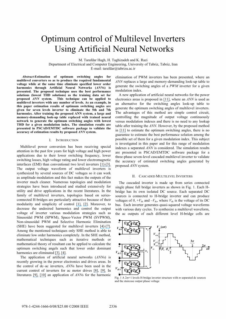
The cascaded inverter is made up from series connected single phase full bridge inverters as shown in Fig. 1. Each H-bridge has its own isolated DC source. Each separated DC sources is connected to H-bridge inverter and can produce voltages of 0, +Vdc and –Vdc, where Vdc is the voltage of its DC bus. Each inverter generates quasi-squared voltage waveforms with various duty cycles. To synthesize a multilevel waveform, the ac outputs of each different level H-bridge cells are
1Q 3Q
2Q4QdcsV
+
+
+
−
−
−
a
o
aoV2dcV
1dcV 1v
sv
2v1Q 3Q
2Q4Q
1Q 3Q
2Q 4Q
1θ 2θ sθ2
3π
2π
π π2tω
)( tVao ω
dcmV
2dcV1dcV
Fig. 1 A 2m+1 levels H-bridge inverter structure with m separated dc sources and the staircase output phase voltage
2336978-1-4244-1666-0/08/$25.00 '2008 IEEE
connected in series. The synthesized voltage waveform is, therefore, the sum of the inverter outputs i.e. v = v1+v2+…+vm. The number of output phase voltage levels in a cascade multilevel inverter is then 2s+1, where s is the number of isolated dc sources in a cascaded multilevel inverter. The staircase output voltage waveform of 2s+1 levels inverter is also shown in Fig. 1. Three phase configuration can be formed by connecting three numbers of these inverters in Y or ∆ [1].
III. SELECTIVE HARMONIC ELIMINATION FOR MULTILEVEL INVERTERS
For the staircase output voltage waveform of multilevel inverter as shown in Fig. 1 there is s degrees of freedom and s -1 number of undesired harmonics can be eliminated from the output phase voltage of inverter, where s is the number of separated dc sources in a cascaded multilevel inverter.
To eliminate specific higher order harmonics and at the same time control the amplitude of fundamental voltage, one must calculate the switching angels sθθθ ,...,, 21 shown in Fig. 1. The Fourier series expansion for the staircase waveform as shown in Fig .1 is as follows
)sin())cos(...
)cos()(cos(4
)( 21,...5,3,1
tnn
nnnV
tV
s
n
dc
ωθ
θθπ
ω
++
+= ∑∞
= (1)
For a seven level case, it is possible to eliminate two
undesired harmonics while maintaining the required fundamental voltage. In order to eliminate the 5th and 7th lower order harmonics, transcendental equations set (2) must be solved in unknown 321 ,, θθθ , where modulation index M is defined as dcsVVM /1= .
⎪⎩
⎪⎨
⎧
=++=++
=++
0)7cos()7cos()7cos(0)5cos()5cos()5cos(
)43()cos()cos()cos(
321
321
321
θθθθθθ
πθθθ M (2)
For the balanced three-phase system applications,
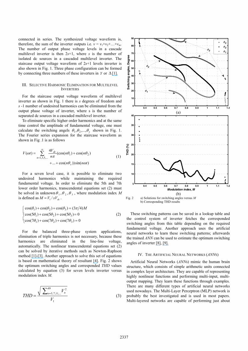
elimination of triple harmonics is not necessary, because these harmonics are eliminated in the line-line voltage, automatically. The nonlinear transcendental equations set (2) can be solved by iterative methods such as Newton-Raphson method [1]-[3]. Another approach to solve this set of equations is based on mathematical theory of resultant [4]. Fig. 2 shows the optimum switching angles and corresponded THD values calculated by equation (3) for seven levels inverter versus modulation index M.
1
49
,...11,7,52
V
VTHD n n∑ == (3)
These switching patterns can be saved in a lookup table and
the control system of inverter fetches the corresponded switching angles from this table depending on the required fundamental voltage. Another approach uses the artificial neural networks to learn these switching patterns; afterwards the trained ANN can be used to estimate the optimum switching angles of inverter [8], [9].
IV. THE ARTIFICIAL NEURAL NETWORKS (ANNS)
Artificial Neural Networks (ANNs) mimic the human brain structure, which consists of simple arithmetic units connected in complex layer architecture. They are capable of representing highly nonlinear functions and performing multi-input, multi-output mapping. They learn these functions through examples. There are many different types of artificial neural networks used nowadays. The Multi-Layer Perceptron (MLP) network is probably the best investigated and is used in most papers. Multi-layered networks are capable of performing just about
0.4 0.5 0.6 0.7 0.8 0.9 1 1.1 1.20
10
20
30
40
50
60
70
80
90
Sw
itch
ing
an
gle
s, D
egre
e
θ3
θ2
θ1
θ1
θ2
θ3
(a)
0.4 0.5 0.6 0.7 0.8 0.9 1 1.1 1.25
10
15
20
25
30
35
40
Modulation index, M
TH
D (%
)
(b)
Fig. 2 a) Solutions for switching angles versus M b) Corresponding THD results
2337

any linear or non-linear computation, and can approximate any reasonable functions. Properly trained networks tend to give reasonable answers when presented with inputs that they have never seen. Typically, a new input will lead to an output similar to the correct output for input vectors used in training that are similar to the new input being presented. This generalization property makes it possible to train a network on a representative set of input/target pairs and get good results without training the network on all possible input/output pairs. The stages of optimum switching angles estimation for multilevel inverters are as follows:
A. Topology of Neural Network
The topology of each ANN to estimate the optimum switching angles of multilevel inverter is illustrated in Fig. 3. The Multi Layer Perceptron (MLP) network is used in this research. As seen from Fig. 3, a network has one hidden layer with one input node, seven nodes in the hidden layer and three output nodes. The input node is corresponding to the desired modulation index and three output nodes corresponding to the related switching angles. The activity functions of neurons in the input and hidden layers are sigmoid and the output nodes use linear activity function which is suitable for function estimation applications.
B. Training patterns
The optimum switching angles of inverter to eliminate the fifth and seventh order harmonic versus modulation index M is plotted in Fig. 2a. Moreover, The THD values for the corresponding solutions is computed by equation (3) and shown in Fig. 2b. From the solutions set shown in Fig. 2a, the solutions exist only for M in the interval of 0.344 to 1.174. Furthermore, the modulation indexes in the interval of 0.632 to 0.787 have two set of solutions with different values for corresponded THD. Since, the ANN system is not able to learn and estimate the switching angles for this range of modulation indexes. To achieve accurate performance of the ANN, only one set of them should be chosen as a training data set for that range of modulation indexes. In [11], the width band branch of solutions which are continuous as a function of M are chosen as the training data set. This width band branch of solutions is shown in Fig. 4. However, the solutions set shown in Fig. 4 don’t have lower THD among the possible set of solutions in the all range of modulation indexes. To clear up this subject, the solutions set corresponding with lower THD is shown in Fig. 5. For M in the interval of 0.774 to 0.787 THD values are
lower than same range of M shown in Fig. 4. The estimation results by the ANN system shown in Fig. 3 for the switching patterns of Fig.5 are illustrated in Fig. 6. Clearly, the trained
1θ
2θ
3θ
M
Fig. 3 Artificial neural network topology
0.5 0.6 0.7 0.8 0.9 1 1.110
20
30
40
50
60
70
80
90
Sw
itch
ing
an
gle
s, D
egre
e
θ3
θ2
θ1
Fig. 4 Width band branch of solutions
0.5 0.6 0.7 0.8 0.9 1 1.10
10
20
30
40
50
60
70
80
90
S
witc
hin
g a
ng
les,
Deg
ree
θ3
θ2
θ1
Fig. 5 Optimum switching angles corresponding to lowest THD
0.5 0.6 0.7 0.8 0.9 1 1.10
10
20
30
40
50
60
70
80
90
Modulation index, M
Sw
itch
ing
an
gle
s, D
egre
e
Optimum switching anglesEstimated switching angles
optimum θ2
estimated θ2 by ANN
Fig. 6 Estimation results for switching angles by one ANN
2338
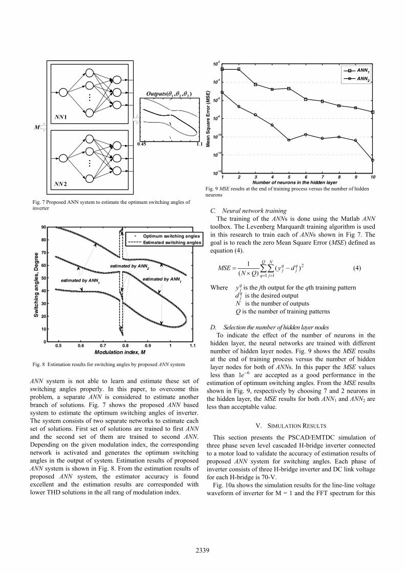
ANN system is not able to learn and estimate these set of switching angles properly. In this paper, to overcome this problem, a separate ANN is considered to estimate another branch of solutions. Fig. 7 shows the proposed ANN based system to estimate the optimum switching angles of inverter. The system consists of two separate networks to estimate each set of solutions. First set of solutions are trained to first ANN and the second set of them are trained to second ANN. Depending on the given modulation index, the corresponding network is activated and generates the optimum switching angles in the output of system. Estimation results of proposed ANN system is shown in Fig. 8. From the estimation results of proposed ANN system, the estimator accuracy is found excellent and the estimation results are corresponded with lower THD solutions in the all rang of modulation index.
C. Neural network training The training of the ANNs is done using the Matlab ANN
toolbox. The Levenberg Marquardt training algorithm is used in this research to train each of ANNs shown in Fig 7. The goal is to reach the zero Mean Square Error (MSE) defined as equation (4).
∑∑= =
−×
=Q
q
N
j
qj
qj dy
QNMSE
1 1
2)()(
1 (4)
Where qjy is the jth output for the qth training pattern
qjd is the desired output
N is the number of outputs Q is the number of training patterns
D. Selection the number of hidden layer nodes To indicate the effect of the number of neurons in the
hidden layer, the neural networks are trained with different number of hidden layer nodes. Fig. 9 shows the MSE results at the end of training process versus the number of hidden layer nodes for both of ANNs. In this paper the MSE values less than 61 −e are accepted as a good performance in the
estimation of optimum switching angles. From the MSE results shown in Fig. 9, respectively by choosing 7 and 2 neurons in the hidden layer, the MSE results for both ANN1 and ANN2 are less than acceptable value.
V. SIMULATION RESULTS
This section presents the PSCAD/EMTDC simulation of three phase seven level cascaded H-bridge inverter connected to a motor load to validate the accuracy of estimation results of proposed ANN system for switching angles. Each phase of inverter consists of three H-bridge inverter and DC link voltage for each H-bridge is 70-V.
Fig. 10a shows the simulation results for the line-line voltage waveform of inverter for M = 1 and the FFT spectrum for this
1 2 3 4 5 6 7 8 9 1010
-14
10-12
10-10
10-8
10-6
10-4
10-2
Number of neurons in the hidden layer
Mea
n S
qu
are
Err
or
(MS
E)
ANN1
ANN2
Fig. 9 MSE results at the end of training process versus the number of hidden neurons
M
),,( 321 θθθOutputs
1NN
2NN
450. 11.
Fig. 7 Proposed ANN system to estimate the optimum switching angles of inverter
0.5 0.6 0.7 0.8 0.9 1 1.10
10
20
30
40
50
60
70
80
90
Modulation index, M
Sw
itch
ing
an
gle
s, D
egre
e
Optimum switching anglesEstimated switching angles
estimated by ANN1
estimated by ANN1
estimated by ANN2
Fig. 8 Estimation results for switching angles by proposed ANN system
2339

waveform up to 37 harmonics is shown in Fig. 10b. FFT analysis of phase voltage and the current waveform of phase a are also shown in Fig. 10c and Fig. 10d respectively.
Another simulation is carried out for M = 0.78, where the second ANN is activated and estimate the optimum switching angles of inverter.
Fig. 11 shows the line-line voltage waveform, the corresponding FFT, current waveform of phase a and THD analysis result of phase voltage for this modulation index.
VI. CONCLUSION
The paper successfully demonstrates the validity of feedforward neural networks for the estimation of optimum switching angles of staircase waveform generated by multilevel inverters. After a large number of training steps, the estimator accuracy was found to be excellent and the estimation results are corresponded with the best performance solutions in the all rang of modulation index. In this paper a separate ANN is considered to estimate another branch of
-500
-400
-300
-200
-100
0
100
200
300
400
500 Vab
(a) The line-line voltage waveform
390.0
0.01 2 3 4 5 6 7 8 9 10 11 12 13 14 15 16 17 18 19 20 21 22 23 24 25 26 27 28 29 30 31 32 33 34 35 36 37
(b) FFT analysis of line-line voltage waveform
220.0
0.01 2 3 4 5 6 7 8 9 10 11 12 13 14 15 16 17 18 19 20 21 22 23 24 25 26 27 28 29 30 31 32 33 34 35 36 37
(c) FFT analysis of phase voltage
-4.0
-3.0
-2.0
-1.0
0.0
1.0
2.0
3.0
4.0 Ia
(d) Cuurent waveform of phase a
Fig. 10 simulatiom results for M = 1
2340

solutions. The proposed approach guarantees the estimation of switching angles which produce the lowest THD among the all possible set of solutions. Simulation results are presented in PSCAD/EMTDC software package for a seven level inverter to validate the accuracy of proposed approach to estimate the optimum switching angles. The estimation principle can be extended to high level inverters.
REFERENCES [1] J. S. Lai and F. Z. Peng, “Multilevel converters—A new breed of power
converters,” IEEE Trans. Ind. Applicat., vol. 32, no. 3, pp. 509–517, May/Jun. 1996.
[2] J. Rodríguez, J. Lai, and F. Peng, “Multilevel inverters: a survey of topologies, controls and applications,” IEEE Trans. Ind. Electron., vol. 49, pp. 724–738, Aug. 2002.
[3] L. M. Tolbert, F. Z. Peng, and T. G. Habetler, “Multilevel converter for large electric drives,” IEEE Trans. Ind. Appl., vol. 35, no. 1, pp. 36–44, Jan./Feb. 1999.
[4] J. N. Chiasson, L. M. Tolbert, K. J. McKenzie, and Z. Du, “Control of a multilevel converter using resultant theory,” IEEE Trans. Contr. Syst. Technol., vol. 11, no. 3, pp. 345–354, May 2003.
[5] V. G. Agelidis, S. Gardellia, M. Marchesoni, R. Salutari, and G. Sciutto, “A new multilevel PWM method: A theoretical analysis,” IEEE Trans. Power Electron., vol. 7, pp. 497–505, July 1992.
[6] R.W. Menzies, P. Steimer, and J. K. Steinke, “Five-level GTO inverters for large induction motor drives,” IEEE Trans. Ind. Applicat., vol. 30, pp. 938–944, July/Aug. 1994.
[7] D. W. Kang, Y. H. Lee, B. S. Suh, C. H. Choi, and D. S. Hyun, “An improved carrierwave-based SVPWM method using phase voltage redundancies for generalized cascaded multilevel inverter topology,” Proc. IEEE APEC’00 Conf., pp. 542–548, 2000.
[8] B. R. Lin and R. G. Hoft, “Power elctronics inverter control with neural networks,” in Proc. IEEE-APEC, 1993, pp. 128–134.
[9] A. M. Trzynadlowski and S. Legowski, “Application of neural networks to the optimal control of three-phase voltage-controlled inverters,” IEEE Trans. Power Electron., vol. 9, pp. 397–404, July 1994.
[10] M. R. Buhl and R. D. Lorenz, “Design and implementation of neural networks for digital current regulation of inverter drives,” in Proc. IEEE-IAS Annu. Meeting, 1991, pp. 415–423.
[11] S. H. Hosseini, H. Taghizadeh, H. Latafat and K. Razi, “Optimum Harmonic Elimination Control Method for Multilevel Inverters Using Artificial Neural Network” in Proc. PCIM China, Shanghai, China, 21-23 March 2007, pp. 267-271.
-300
-200
-100
0
100
200
300 Vab
(a) The line-line voltage waveform
350.0
0.01 2 3 4 5 6 7 8 9 10 11 12 13 14 15 16 17 18 19 20 21 22 23 24 25 26 27 28 29 30 31 32 33 34 35 36 37
(b) FFT analysis of line-line voltage waveform
200.0
0.01 2 3 4 5 6 7 8 9 10 11 12 13 14 15 16 17 18 19 20 21 22 23 24 25 26 27 28 29 30 31 32 33 34 35 36 37
(c) FFT analysis of phase voltage
-4.0
-3.0
-2.0
-1.0
0.0
1.0
2.0
3.0
4.0 Ia
(d) Cuurent waveform of phase a
Fig. 11 simulatiom results for M = 0.78
2341
Copyright © 2022 FDOKUMEN