State of the Art of the Techniques for Grid Forming Inverters to ...
25
Energies 2022, 15, 1879. https://doi.org/10.3390/en15051879 www.mdpi.com/journal/energies Review State of the Art of the Techniques for Grid Forming Inverters to Solve the Challenges of Renewable Rich Power Grids Efaf Bikdeli 1 , Md. Rabiul Islam 2, *, Md. Moktadir Rahman 3 and Kashem M. Muttaqi 2 1 Department of Electrical and Computer Engineering, Babol Noshirvani University of Technology, Babol 47148‐71167, Iran; [email protected] 2 School of Electrical, Computer and Telecommunications Engineering, Faculty of Engineering and Information Sciences, University of Wollongong, Wollongong, NSW 2522, Australia; [email protected] 3 Energy & Grid Division, Ingeteam Australia Pty Ltd., Wollongong, NSW 2500, Australia; [email protected] * Correspondence: [email protected]; Tel.: +61‐2‐4221‐3624 Abstract: To mitigate the fast‐growing demand of electrical energy, the use of renewable energy resources, e.g., solar and wind, can offer an environmentally friendly and sustainable solution. Due to their intermittent nature, the grid connected operation of renewable energy resources provides a better performance compared to the standalone operation. However, the massive penetration of power electronic inverter/converter‐interfaced renewable resources in power systems introduces new issues, such as voltage and frequency instabilities, because of their inherent low inertia properties. As a consequence, these issues may lead to serious problems, such as system blackouts. Therefore, there is an immediate demand to solve these new issues and ensure the normal performance of the power system with the large penetration of renewable energy resources. To achieve this, grid connected inverters/converters are designed to address these problems and behave as synchronous generators, which is possible with grid forming (GFM) inverters/converters concepts. This paper reviews the recent advancement of GFM converters for solving emerging issues related to the renewable rich power grids. It also provides a comprehensive review on frequency deviations and power system stability issues in low‐inertia systems and recent advancements in control methods for harmonic mitigation. It is expected that this paper will help the research community to enhance the technology further to solve the challenges in renewable rich power grids. Keywords: renewable energy resources; grid integration; grid forming converters; rate of change of frequency; low inertia; virtual inertia; system stability; harmonic mitigation; black start capability 1. Introduction Electrical energy is the most common and widely used form of energy as it has many advantages, e.g., easy to transform and transport. The generation of electrical energy from traditional sources, e.g., coal, oil, and gas, produces vast CO2 gases, which heavily affect the environment and consequently destroy the sustainability of the world. On the other hand, the generation of electrical energy from renewable energy resources, e.g., solar and wind, can keep the environment sustainable without any emission of CO2. Many countries have already set their target to generate a significant percentage of electrical energy from renewable resources to keep the environment sustainable. Many governments and industries are working closely to achieve the net‐zero carbon emissions goal. In many countries, traditional fossil‐fuel‐based power plants are being replaced by renewable‐ energy‐based power plants, e.g., solar photovoltaic and wind plants. Due to their intermittent nature, the grid connected operation of renewable energy resources provides a better performance compared to the standalone operation. Power electronic Citation: Bikdeli, E.; Islam, M. R.; Rahman, M.M.; Muttaqi, K.M. State of the Art of the Techniques for Grid Forming Inverters to Solve the Challenges of Renewable Rich Power Grids. Energies 2022, 15, 1879. https://doi.org/10.3390/en15051879 Academic Editor: Paolo Mattavelli Received: 30 January 2022 Accepted: 2 March 2022 Published: 3 March 2022 Publisher’s Note: MDPI stays neutral with regard to jurisdictional claims in published maps and institutional affiliations. Copyright: © 2022 by the authors. Licensee MDPI, Basel, Switzerland. This article is an open access article distributed under the terms and conditions of the Creative Commons Attribution (CC BY) license (https://creativecommons.org/license s/by/4.0/).
-
Upload
khangminh22 -
Category
Documents
-
view
3 -
download
0
Transcript of State of the Art of the Techniques for Grid Forming Inverters to ...
Energies 2022, 15, 1879. https://doi.org/10.3390/en15051879 www.mdpi.com/journal/energies
Review
State of the Art of the Techniques for Grid Forming Inverters to
Solve the Challenges of Renewable Rich Power Grids
Efaf Bikdeli 1, Md. Rabiul Islam 2,*, Md. Moktadir Rahman 3 and Kashem M. Muttaqi 2
1 Department of Electrical and Computer Engineering, Babol Noshirvani University of Technology,
Babol 47148‐71167, Iran; [email protected] 2 School of Electrical, Computer and Telecommunications Engineering, Faculty of Engineering and
Information Sciences, University of Wollongong, Wollongong, NSW 2522, Australia; [email protected] 3 Energy & Grid Division, Ingeteam Australia Pty Ltd., Wollongong, NSW 2500, Australia;
* Correspondence: [email protected]; Tel.: +61‐2‐4221‐3624
Abstract: To mitigate the fast‐growing demand of electrical energy, the use of renewable energy
resources, e.g., solar and wind, can offer an environmentally friendly and sustainable solution. Due
to their intermittent nature, the grid connected operation of renewable energy resources provides a
better performance compared to the standalone operation. However, the massive penetration of power electronic inverter/converter‐interfaced renewable resources in power systems introduces
new issues, such as voltage and frequency instabilities, because of their inherent low inertia properties. As a consequence, these issues may lead to serious problems, such as system blackouts.
Therefore, there is an immediate demand to solve these new issues and ensure the normal performance of the power system with the large penetration of renewable energy resources. To achieve this, grid connected inverters/converters are designed to address these problems and behave as synchronous generators, which is possible with grid forming (GFM) inverters/converters
concepts. This paper reviews the recent advancement of GFM converters for solving emerging issues related to the renewable rich power grids. It also provides a comprehensive review on frequency deviations and power system stability issues in low‐inertia systems and recent advancements in control methods for harmonic mitigation. It is expected that this paper will help
the research community to enhance the technology further to solve the challenges in renewable rich
power grids.
Keywords: renewable energy resources; grid integration; grid forming converters; rate of change of
frequency; low inertia; virtual inertia; system stability; harmonic mitigation; black start capability
1. Introduction
Electrical energy is the most common and widely used form of energy as it has many
advantages, e.g., easy to transform and transport. The generation of electrical energy from
traditional sources, e.g., coal, oil, and gas, produces vast CO2 gases, which heavily affect
the environment and consequently destroy the sustainability of the world. On the other
hand, the generation of electrical energy from renewable energy resources, e.g., solar and
wind, can keep the environment sustainable without any emission of CO2. Many countries
have already set their target to generate a significant percentage of electrical energy from
renewable resources to keep the environment sustainable. Many governments and
industries are working closely to achieve the net‐zero carbon emissions goal. In many
countries, traditional fossil‐fuel‐based power plants are being replaced by renewable‐
energy‐based power plants, e.g., solar photovoltaic and wind plants. Due to their
intermittent nature, the grid connected operation of renewable energy resources provides
a better performance compared to the standalone operation. Power electronic
Citation: Bikdeli, E.; Islam, M. R.;
Rahman, M.M.; Muttaqi, K.M. State
of the Art of the Techniques for Grid
Forming Inverters to Solve the
Challenges of Renewable Rich
Power Grids. Energies 2022, 15, 1879.
https://doi.org/10.3390/en15051879
Academic Editor: Paolo Mattavelli
Received: 30 January 2022
Accepted: 2 March 2022
Published: 3 March 2022
Publisher’s Note: MDPI stays
neutral with regard to jurisdictional
claims in published maps and
institutional affiliations.
Copyright: © 2022 by the authors.
Licensee MDPI, Basel, Switzerland.
This article is an open access article
distributed under the terms and
conditions of the Creative Commons
Attribution (CC BY) license
(https://creativecommons.org/license
s/by/4.0/).
Energies 2022, 15, 1879 2 of 25
inverters/converters are the key components in interfacing renewable energy resources to
the power grids.
As more and more renewable resources are integrated into the power grids, electric
power systems are experiencing a transition from a synchronous generator‐based control
to inverter/converter‐based resources. Conventionally, converter‐based sources have
been working in the grid‐following mode, as a current source in the system [1,2]. In this
mode, ancillary services, such as steady‐state voltage support through reactive power
injection, fault ride through, dynamic voltage support, and primary frequency support in
terms of droop and inertial response, are available [3–5]. However, these supports are not
effective enough under a disturbance situation, because of problems, such as sensing and
actuation delays, decreasing synchronous generation in weak grids, and challenges in the
phase locked loop (PLL) and the rate of change of frequency measurement [3,6–8]. Due to
the delay in frequency estimation and control response time in this mode, the concept of
synthetic inertia cannot effectively limit the frequency derivative. Grid‐forming (GFM) converters are a reliable alternative for grid‐following (GFL)
converters, which behave as a controllable voltage source and create voltage and
frequency in the system [3,9,10]. In the grid‐forming mode, the converter is robustly
synchronized to the grid and, in the case of any disturbance, without the need for a PLL,
the problem is solved quickly [11]. In terms of frequency stability and short‐term voltage
stability, grid‐forming has a superior dynamic behavior compared to GFL and
synchronous machines [12–14]. Additionally, these are necessary for islanded operations
and black start services [11]. Therefore, these converters are a promising method for the
high penetration of renewable energy sources [9,10,15] and have a number of system
functionalities, such as superior synchronization in weak grid situations, stand‐alone
functions and decentralized power sharing of different sources in islanded operations,
which is not possible in GFL modes [16]. Table 1 shows a comparison of GFL and GFM
inverter in terms of their capabilities.
Table 1. Comparison of GFL and GFM inverter capabilities.
GFL GFM Current source inverter Voltage source inverter
Controlling the current and phase angle Controlling the voltage amplitude and frequency Following the grid Adjusting voltage and frequency of the grid
Controlling the active and reactive power Balancing loads instantaneously
‐ Operating in islanded mode and weak grid condition
‐ Contribution to system inertia
‐ Black start capability
This paper reviews the recent advancements of GFM converters for solving emerging
issues related to renewable rich power grids. It also provides a comprehensive review on
frequency deviations and power system stability issues, including resonance stability and
converter‐driven stability in low‐inertia systems, and recent advancements in control
methods, including the virtual impedance‐based control method and the filtering method
for harmonic mitigation.
This paper is organized as follows. First, the importance of limiting of the rate of
change of frequency (RoCoF) in low‐inertia power systems is discussed and different
schemes for this purpose are reviewed in Section 2. After that, the black start capability of
GFM converters is defined in Section 3. Power system stability problems based on
different instability phenomena and current advanced methods are summarized in
Section 4. Section 5 describes various control methods used for harmonic mitigation in
GFM converters. Finally, the paper is summarized with a conclusion and future scope in
Section 6 and Section 7, respectively.
Energies 2022, 15, 1879 3 of 25
2. Rate of Change of Frequency in a Low‐Inertia Power System
With the high penetration of converter‐interfaced renewables and the replacement of
synchronous generators by them, the inertia of the modern power system is reduced.
Consequently, there is a possibility that the grid frequency and RoCoF are increased
compared to its normal operation range, which can cause problems, such as load shedding
and system blackout [17]. Inertia represents the physical characteristic of the rotating
machines to respond an immediate change in the active power output during any
frequency change in the network. Therefore, increasing the inertia of the power system
and limiting the RoCoF of the system are really important. To address the aforementioned
problems, the work in [18] provides a synthetic inertia control with the ability of RoCoF
mitigation and considers the inverter synchronization dynamics. The proposed controller
is regulated to have a fast settling time without any oscillations.
In [19], a new frequency shaping control is proposed to control a GFM converter
frequency of a low‐inertia power system. In this study, the frequency dynamics of the
system are modeled into a first‐order one with acceptable steady‐state frequency
deviations and RoCoF after a sudden change in power. The first order frequency response
of the system causes the system to reach its new steady‐state without any frequency nadir.
In [20], in order to emulate the inertia of synchronous generators and primary frequency
control, a synchronous active power control strategy is proposed, which incorporates
inertia emulation, damping and P‐f droop control as an alternative to emulate the inertia
characteristics of a synchronous machine.
Additionally, a virtual synchronous generator (VSG) with emulating the swing
equation of a synchronous generator can provide inertia support for the system. This
control scheme needs an energy storage system to limit the grid frequency deviations by
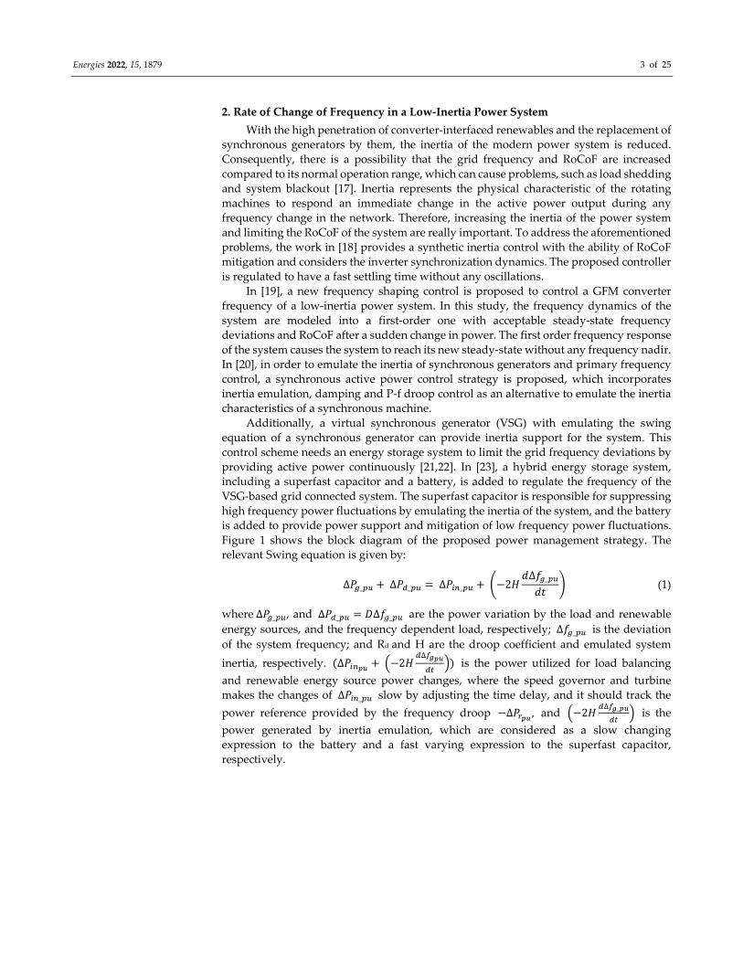
providing active power continuously [21,22]. In [23], a hybrid energy storage system,
including a superfast capacitor and a battery, is added to regulate the frequency of the
VSG‐based grid connected system. The superfast capacitor is responsible for suppressing
high frequency power fluctuations by emulating the inertia of the system, and the battery
is added to provide power support and mitigation of low frequency power fluctuations.
Figure 1 shows the block diagram of the proposed power management strategy. The
relevant Swing equation is given by:
∆𝑃 _ ∆𝑃 _ ∆𝑃 _ 2𝐻𝑑∆𝑓 _
𝑑𝑡 (1)
where ∆𝑃 _ , and ∆𝑃 _ 𝐷∆𝑓 _ are the power variation by the load and renewable
energy sources, and the frequency dependent load, respectively; ∆𝑓 _ is the deviation
of the system frequency; and Rd and H are the droop coefficient and emulated system
inertia, respectively. ∆𝑃 2𝐻∆
is the power utilized for load balancing
and renewable energy source power changes, where the speed governor and turbine
makes the changes of ∆𝑃 _ slow by adjusting the time delay, and it should track the
power reference provided by the frequency droop ∆𝑃 , and 2𝐻∆ _
is the
power generated by inertia emulation, which are considered as a slow changing
expression to the battery and a fast varying expression to the superfast capacitor,
respectively.
Energies 2022, 15, 1879 4 of 25
1
2Hs
P ref_pu
d
P in_pu
P g_pu
P f_pu f g_pu
DP d_pu
1
R
P r_pu
Speed governor & turbine
Figure 1. Block diagram of the proposed power management strategy in [23].
In [24], in order to limit the RoCoF and steady‐state frequency deviation of the system
in the absence of inertia response, a new scheme based on the energy storage system
analysis with VSG control is proposed. In the paper, the capacity and energy capacity of
the energy storage system are studied to provide the required power support in different
frequency adjustment stages. In [25], a new extended VSG control scheme is proposed to
improve the frequency support of the hybrid low‐inertia system. This scheme provides
inertia along with fast frequency response for the system by controlling the active power
of the converter interfaced energy storage system and adding a fast frequency response
block to the control system.
3. Black Start Capability
Due to growing penetration of the power electronic‐converter‐based generators and
continuous displacement of the synchronous generators, the ability to restore the power
system from an outage is reducing. This service is usually provided by the black‐start
units (e.g., diesel generators and small gas turbines) that can self‐energize and are able to
work as a voltage source to provide the required active and reactive power to energize
the components that require high inrush currents (e.g., motors, transformers, and lines).
The GFL converter requires an external grid and/or grid references to start up. Therefore,
it cannot provide black start support.
With the advance of GFM, converters with renewable energy resources and
interfacing battery energy storage can provide black start capability [26]. This is
performed through a soft energization of the connected network, where voltage is linearly
ramped up to eliminate the inrush current and harmonics of the transformers and motors.
This slow voltage ramp up reduces the chances of tripping the protection relays due to a
high inrush current and prevents harmonic overvoltage. The black start capability of four
different grid forming control methods, e.g., droop, power synchronization, virtual
synchronous machines (VSM), and matching under voltage and active power reference
disturbances are compared in [27]. The study shows that VSM is superior to others in
different disturbances. In [28], a modified VSM‐based grid connected control using a
ramping voltage reference for a black‐start operation is proposed. A direct voltage
control‐based grid forming approach with the black‐start capability of wind turbine
control is proposed in [29]. However, all the above studies are limited to the small section
of local distribution network restorations and are not tested for the large system restart
process.
4. Power System Stability
Power system stability is another important problem related to power system
performance, which can cause severe issues, such as blackouts with extraordinary losses
[30]. Therefore, it becomes an outstanding aspect of research [31]. The classification of the
traditional power systems based on the synchronous generator [32] needs to be redefined
due to the high penetration of converter‐ or inverter‐based generators into the grid. The
rotor angle, frequency and voltage stabilities are significantly impacted by the increased

Energies 2022, 15, 1879 5 of 25
penetration of the converter‐based generators as the system inertia will be reduced due to
the displacement of the synchronous generators by the converter‐based generators. The
reduction in the system inertia results in more faster and frequent frequency excursions,
cause instability in the controls of converter‐based generators. Likewise, the fast current
injection from the converter‐based generators move the voltage rapidly in the low‐inertia
grid, which can cause voltage stability issues. There are two new stability classifications
that are considered in the power system stability, namely, resonance stability and
converter‐driven stability, and are shown in Figure 2 [33].
Figure 2. Different categories of power system stability.
4.1. Rotor Angle Stability
With the high penetration of low‐inertia converter‐based resources and the
sensitivity of these converters to weak and faulty grids that threaten the synchronization
stability of the system, various grid‐synchronization methods have been proposed [34,35].
Some of them have analyzed the synchronization stability of the system under small
disturbances (small‐signal synchronization stability), while others have analyzed the
transient stability of the system and proposed various stabilization methods.
4.1.1. Transient Stability
GFM converter control methods have attracted more attention due to their
advantages over the GFL converter control methods in the case of weak and low‐inertia
power systems [34,36]. Although GFM converters can directly control the voltage and
frequency, they cannot limit the converter current and fault‐ride‐through current in grid
transient conditions, such as short circuit faults [37]. However, due to the low current rate
of switches in these converters, it is important to use current limitations to limit
overcurrent and protect switches during voltage drop events [38]. In order to achieve the
current limitation, various control methods are used, such as changing the operation to
the GFL mode [39,40], changing the voltage controller by adding an inner‐current control
loop [41,42], using virtual impedance [43,44], among others. However, limiting the current
with different approaches can affect the system stability and the GFM converters have to
stay stable and synchronized with the grid after large disturbances, which is defined as
the transient stability [45,46].
In the literature, various methods are used to limit the fault currents. Limiting the
inverter current may lead to a poor post‐fault transient, and improper adjustment of the
converter controller can also lead to oscillatory transients and overshoots in post‐fault
responses [39,47]. However, in some cases, only current limitation is used, while in other
cases oscillations and post‐fault recovery techniques are adopted. In some papers, the
large disturbances that do not stimulate the system overcurrent limitation are considered.
Table 2 summarizes the different methods for transient stability improvement in
GFM converters on the basis of three categories, i.e., current limitation, current limitation
along with post‐fault improvement, and without overcurrent stimulation.
Energies 2022, 15, 1879 6 of 25
Table 2. Methods used for transient stability improvement in GFM converters.
Categories Methods
Current limitation
Limiting the converter output voltage [48] Using circular current limiter in unified virtual oscillator control [49]
Considering the impact of current reference angle [50] Using virtual admittance [51]
Current limitation along with post‐fault
improvement
Using virtual impedance and adaptive parameters of the droop controller
[52] Adjusting power references based on the voltage drop along with a virtual
resistance [35] Using adaptive virtual resistance according to the intensity of the post fault
oscillations [53]
Without overcurrent stimulation
Mode adaptive power angle control scheme [54]
Improving the large signal angle stability by changing the internal voltage
control [55]
Use of frequency deviation through a high pass filter in combination with
active power control loop [56]
A. Current limitation
The use of the current limitation increases the critical clearing angle, but the system
depends on the fault duration, and if the fault is cleared after the critical clearing angle,
the part of the system that is affected loses its synchronization with the rest of the system
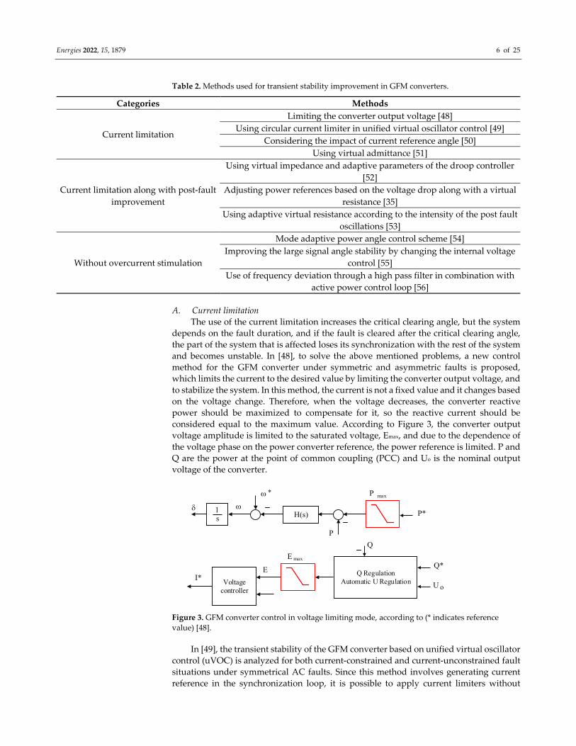
and becomes unstable. In [48], to solve the above mentioned problems, a new control
method for the GFM converter under symmetric and asymmetric faults is proposed,
which limits the current to the desired value by limiting the converter output voltage, and
to stabilize the system. In this method, the current is not a fixed value and it changes based
on the voltage change. Therefore, when the voltage decreases, the converter reactive
power should be maximized to compensate for it, so the reactive current should be
considered equal to the maximum value. According to Figure 3, the converter output
voltage amplitude is limited to the saturated voltage, Emax, and due to the dependence of
the voltage phase on the power converter reference, the power reference is limited. P and
Q are the power at the point of common coupling (PCC) and Uo is the nominal output
voltage of the converter.
P
P*
max
P
Q
U
Q*
o
E max
E Q RegulationAutomatic U Regulation
H(s)
Voltage controller
I*
1s
Figure 3. GFM converter control in voltage limiting mode, according to (* indicates reference
value) [48].
In [49], the transient stability of the GFM converter based on unified virtual oscillator
control (uVOC) is analyzed for both current‐constrained and current‐unconstrained fault
situations under symmetrical AC faults. Since this method involves generating current
reference in the synchronization loop, it is possible to apply current limiters without
Energies 2022, 15, 1879 7 of 25
saturating the outer loop. When the output current of the converter extends beyond an
overcurrent threshold, the controller operation changes to the current‐constrained mode.
In this condition, by using the circular limiter, the magnitude of the current reference is
limited and keeps the angle unchanged. While in the current‐unconstrained mode, fault
current is limited through the GFM nature.
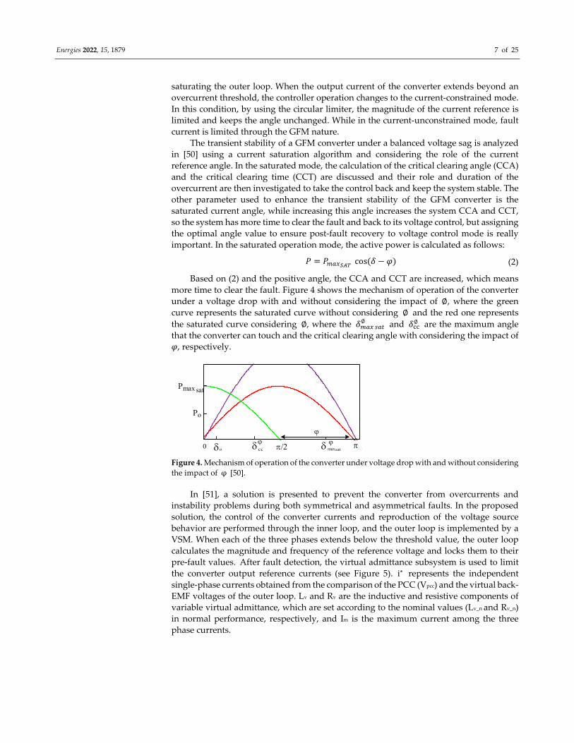
The transient stability of a GFM converter under a balanced voltage sag is analyzed
in [50] using a current saturation algorithm and considering the role of the current
reference angle. In the saturated mode, the calculation of the critical clearing angle (CCA)
and the critical clearing time (CCT) are discussed and their role and duration of the
overcurrent are then investigated to take the control back and keep the system stable. The
other parameter used to enhance the transient stability of the GFM converter is the
saturated current angle, while increasing this angle increases the system CCA and CCT,
so the system has more time to clear the fault and back to its voltage control, but assigning
the optimal angle value to ensure post‐fault recovery to voltage control mode is really
important. In the saturated operation mode, the active power is calculated as follows:
𝑃 𝑃 cos 𝛿 𝜑 (2)
Based on (2) and the positive angle, the CCA and CCT are increased, which means
more time to clear the fault. Figure 4 shows the mechanism of operation of the converter
under a voltage drop with and without considering the impact of ∅, where the green
curve represents the saturated curve without considering ∅ and the red one represents the saturated curve considering ∅, where the 𝛿∅ and 𝛿∅ are the maximum angle
that the converter can touch and the critical clearing angle with considering the impact of
𝜑, respectively.
Po
maxsat0
max satP
o cc
Figure 4. Mechanism of operation of the converter under voltage drop with and without considering
the impact of φ [50].
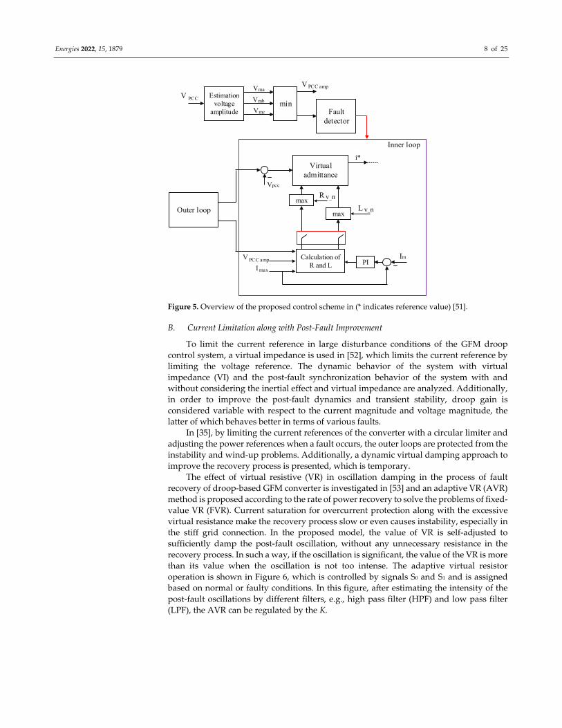
In [51], a solution is presented to prevent the converter from overcurrents and
instability problems during both symmetrical and asymmetrical faults. In the proposed
solution, the control of the converter currents and reproduction of the voltage source
behavior are performed through the inner loop, and the outer loop is implemented by a
VSM. When each of the three phases extends below the threshold value, the outer loop
calculates the magnitude and frequency of the reference voltage and locks them to their
pre‐fault values . After fault detection, the virtual admittance subsystem is used to limit
the converter output reference currents (see Figure 5). i∗ represents the independent single‐phase currents obtained from the comparison of the PCC (Vpcc) and the virtual back‐
EMF voltages of the outer loop. Lv and Rv are the inductive and resistive components of
variable virtual admittance, which are set according to the nominal values (Lv_n and Rv_n)
in normal performance, respectively, and Im is the maximum current among the three
phase currents.
Energies 2022, 15, 1879 8 of 25
Virtual admittance
max
max
Calculation of R and L
R v_n
L v_n
I max
V PCC amp PIIm
i*
Estimation voltage
amplitude
Vma
Vmc
Vmb minFault
detector
V PCC amp
V PCC
Inner loop
Outer loop
Vpcc
Figure 5. Overview of the proposed control scheme in (* indicates reference value) [51].
B. Current Limitation along with Post‐Fault Improvement
To limit the current reference in large disturbance conditions of the GFM droop
control system, a virtual impedance is used in [52], which limits the current reference by
limiting the voltage reference. The dynamic behavior of the system with virtual
impedance (VI) and the post‐fault synchronization behavior of the system with and
without considering the inertial effect and virtual impedance are analyzed. Additionally,
in order to improve the post‐fault dynamics and transient stability, droop gain is
considered variable with respect to the current magnitude and voltage magnitude, the
latter of which behaves better in terms of various faults.
In [35], by limiting the current references of the converter with a circular limiter and
adjusting the power references when a fault occurs, the outer loops are protected from the
instability and wind‐up problems. Additionally, a dynamic virtual damping approach to
improve the recovery process is presented, which is temporary.
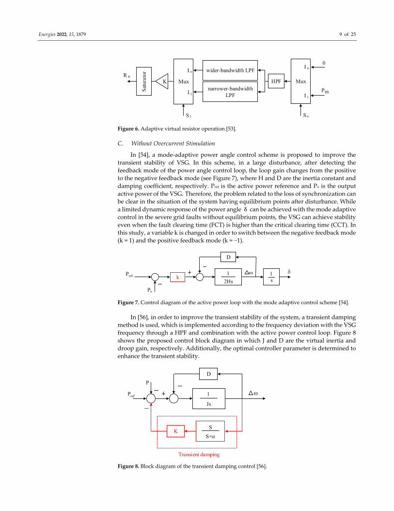
The effect of virtual resistive (VR) in oscillation damping in the process of fault
recovery of droop‐based GFM converter is investigated in [53] and an adaptive VR (AVR)
method is proposed according to the rate of power recovery to solve the problems of fixed‐
value VR (FVR). Current saturation for overcurrent protection along with the excessive
virtual resistance make the recovery process slow or even causes instability, especially in
the stiff grid connection. In the proposed model, the value of VR is self‐adjusted to
sufficiently damp the post‐fault oscillation, without any unnecessary resistance in the
recovery process. In such a way, if the oscillation is significant, the value of the VR is more
than its value when the oscillation is not too intense. The adaptive virtual resistor
operation is shown in Figure 6, which is controlled by signals S0 and S1 and is assigned
based on normal or faulty conditions. In this figure, after estimating the intensity of the
post‐fault oscillations by different filters, e.g., high pass filter (HPF) and low pass filter
(LPF), the AVR can be regulated by the K.
Energies 2022, 15, 1879 9 of 25
Mux
I o
I 1
0
Pm
S o
HPF
wider-bandwidth LPF
narrower-bandwidth LPF
K
Sat
urat
orR vMux
I o
I 1
S 1
Figure 6. Adaptive virtual resistor operation [53].
C. Without Overcurrent Stimulation
In [54], a mode‐adaptive power angle control scheme is proposed to improve the
transient stability of VSG. In this scheme, in a large disturbance, after detecting the
feedback mode of the power angle control loop, the loop gain changes from the positive
to the negative feedback mode (see Figure 7), where H and D are the inertia constant and
damping coefficient, respectively. Pref is the active power reference and Po is the output
active power of the VSG. Therefore, the problem related to the loss of synchronization can be clear in the situation of the system having equilibrium points after disturbance. While
a limited dynamic response of the power angle δ can be achieved with the mode adaptive
control in the severe grid faults without equilibrium points, the VSG can achieve stability
even when the fault clearing time (FCT) is higher than the critical clearing time (CCT). In
this study, a variable k is changed in order to switch between the negative feedback mode
(k = 1) and the positive feedback mode (k = −1).
P
P
o
k 1
sref 1
2Hs
D
Figure 7. Control diagram of the active power loop with the mode adaptive control scheme [54].
In [56], in order to improve the transient stability of the system, a transient damping
method is used, which is implemented according to the frequency deviation with the VSG
frequency through a HPF and combination with the active power control loop. Figure 8
shows the proposed control block diagram in which J and D are the virtual inertia and
droop gain, respectively. Additionally, the optimal controller parameter is determined to
enhance the transient stability.
P
P ref 1
Js
D
K
Transient damping
S+
S
Figure 8. Block diagram of the transient damping control [56].
Energies 2022, 15, 1879 10 of 25
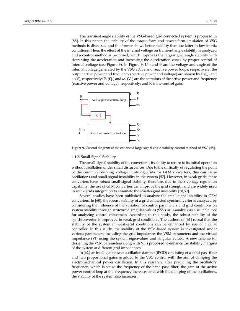
The transient angle stability of the VSG‐based grid connected system is proposed in
[55]. In this paper, the stability of the torque‐form and power‐form emulation of VSG
methods is discussed and the former shows better stability than the latter in low‐inertia
conditions. Then, the effect of the internal voltage on transient angle stability is analyzed
and a control method is proposed, which improves the large‐signal angle stability with
decreasing the acceleration and increasing the deceleration zones by proper control of
internal voltage (see Figure 9). In Figure 9, Uref and θ are the voltage and angle of the
internal voltage generated by the VSG active and reactive power loops, respectively; the
output active power and frequency (reactive power and voltage) are shown by P (Q) and
ω (V), respectively; Po (Qo) and ωo (Vo) are the setpoints of the active power and frequency
(reactive power and voltage), respectively; and K is the control gain.
Po
Active power control loopo
P
Qo
Reactive power control loop
Vo
Q
V
U ref
K | |.
Figure 9. Control diagram of the enhanced large signal angle stability control method of VSG [55].
4.1.2. Small‐Signal Stability
The small‐signal stability of the converter is its ability to return to its initial operation
without oscillation under small disturbances. Due to the difficulty of regulating the point
of the common coupling voltage in strong grids for GFM converters, this can cause
oscillations and small‐signal instability in the system [57]. However, in weak grids, these
converters have robust small‐signal stability, therefore, due to their voltage regulation
capability, the use of GFM converters can improve the grid strength and are widely used
in weak grids integration to eliminate the small‐signal instability [58,59].
Several studies have been published to analyze the small‐signal stability in GFM
converters. In [60], the robust stability of a grid connected synchronverter is analyzed by
considering the influence of the variation of control parameters and grid conditions on
system stability through structured singular values (SSV) or μ‐analysis as a suitable tool
for analyzing control robustness. According to this study, the robust stability of the
synchronverter is improved in weak grid conditions. The authors of [61] reveal that the
stability of the system in weak‐grid conditions can be enhanced by use of a GFM
controller. In this study, the stability of the VSM‐based system is investigated under
various parameters, including the grid impedance, the VSM parameters and the virtual
impedance (VI) using the system eigenvalues and singular values. A new scheme for
designing the VSM parameters along with VI is proposed to enhance the stability margins
of the system at different grid impedances.
In [62], an intelligent power oscillation damper (iPOD) consisting of a band‐pass filter
and two proportional gains is added to the VSG control with the aim of damping the
electromechanical power oscillation. In this research, after predicting the oscillatory
frequency, which is set as the frequency of the band‐pass filter, the gain of the active
power control loop at this frequency increases and, with the damping of the oscillations,
the stability of the system also increases.
Energies 2022, 15, 1879 11 of 25
4.2. Resonance Stability and Converter‐Driven Stability
The resonance stability is incorporated with mainly subsynchronous resonance (SSR)
associated either to electromechanical (torsional) or purely electrical resonance. The SSR
can be formed into two ways: resonance between series compensating network elements
and mechanical torsional frequencies of the conventional synchronous generator shat; and
resonance series compensating network elements and the electrical characteristics of the
generator. In the case of the electrical resonance, it is occurred due to the effective
reactance (self‐excitation effect) of the DFIG (Double Feed Induction Generator) wind‐
turbine generators, which creates electrical resonance with the series compensation
network elements [63].
In regard to the converter‐driven stability, it is associated with the power electronic
converter controls. The slow‐ and fast‐interaction timescale controls of the converter‐
based generators may create cross couplings with the electromechanical dynamics of
machines and the electromagnetic transients of the network. As a result, a wide range of
low‐to‐high frequency oscillations (0.5 Hz to several kHz) can be observed. For example,
the interactions of the fast inner‐current loops of the converter‐based generators with
passive network components may cause several kilohertz high frequency oscillations [64].
It is reported in [65] that the VSG in a low‐inertia grid may initiate super‐synchronous
stability issues due to converter control interactions. Therefore, a properly tuned VSG
controller will reduce these types of fast oscillations [66]. However, it will require more
investigation on how to optimize the VSG controller in different network conditions.
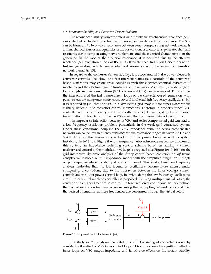
The impedance interaction between a VSG and series compensated grid can lead to
a low‐frequency oscillation problem, particularly in the weak grid connected system.
Under these conditions, coupling the VSG impedance with the series compensated
network can cause low frequency subsynchronous resonance ranges between 0.5 Hz and
50/60 Hz, since this resonance can lead to further power losses as well as system
instability. In [67], to mitigate the low frequency subsynchronous resonance problem of
this system, an impedance reshaping control scheme based on adding a current
feedforward control to the modulation voltage is proposed (see Figure 10). In [68], for the
grid‐interactive dynamic analysis of the droop‐control‐based converter an αβ‐frame
complex‐value‐based output impedance model with the simplified single input–single
output impedance‐based stability study is proposed. This study, based on frequency
analysis, indicates that the low frequency oscillations become more intense under
stringent grid conditions, due to the interaction between the inner voltage, current
controls and the outer power control loop. In [69], to damp the low frequency oscillations,
a multirotor virtual machine controller is proposed. By using multiple virtual rotors, the
converter has higher freedom to control the low frequency oscillations. In this method,
the desired oscillation frequencies are set using the decoupling network block and then
the desired attenuation at these frequencies are performed through the virtual rotors.
P
P
o
ref APC
Q
Q
o
ref RPC
Reference Generator
Vref
Inner loopm
Virtual Z
io
Figure 10. Proposed control scheme in [67].
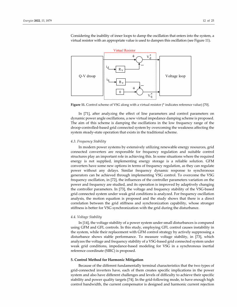
The study in [70] analyzes the stability of a VSG‐based grid connected system by
considering the effect of VSG inner control loops. This study shows the significant effect of
inner loops on VSG output impedance and its adverse effects on the system stability.
Energies 2022, 15, 1879 12 of 25
Considering the inability of inner loops to damp the oscillation that enters into the system, a
virtual resistor with an appropriate value is used to dampen this oscillation (see Figure 11).
Voltage loop
Rv
0
id
Rviq
Q-V droop
*Vd
*Vq
Virtual Resistor
Figure 11. Control scheme of VSG along with a virtual resistor (* indicates reference value) [70].
In [71], after analyzing the effect of line parameters and control parameters on
dynamic power angle oscillations, a new virtual impedance damping scheme is proposed.
The aim of this scheme is damping the oscillations in the low frequency range of the
droop‐controlled‐based grid connected system by overcoming the weakness affecting the
system steady‐state operation that exists in the traditional scheme.
4.3. Frequency Stability
In modern power systems by extensively utilizing renewable energy resources, grid
connected converters are responsible for frequency regulation and suitable control
structures play an important role in achieving this. In some situations where the required
energy is not supplied, implementing energy storage is a reliable solution. GFM
converters have some new options in terms of frequency regulation, as they can regulate
power without any delays. Similar frequency dynamic response to synchronous
generators can be achieved through implementing VSG control. To overcome the VSG
frequency oscillation, in [72], the influences of the controller parameters variation on the
power and frequency are studied, and its operation is improved by adaptively changing
the controller parameters. In [73], the voltage and frequency stability of the VSG‐based
grid connected system under weak grid conditions is analyzed. For frequency oscillation
analysis, the motion equation is proposed and the study shows that there is a direct
correlation between the grid stiffness and synchronization capability, whose stronger
stiffness is better for VSG synchronization with the grid during the disturbance.
4.4. Voltage Stability
In [14], the voltage stability of a power system under small disturbances is compared
using GFM and GFL controls. In this study, employing GFL control causes instability in
the system, while their replacement with GFM control strategy by actively suppressing a
disturbance shows stable performance. To measure voltage stability, in [73], which
analyzes the voltage and frequency stability of a VSG‐based grid connected system under
weak grid conditions, impedance‐based modeling for VSG in a synchronous inertial
reference coordinate (SIRC) is proposed.
5. Control Method for Harmonic Mitigation
Because of the different fundamentally terminal characteristics that the two types of
grid‐connected inverters have, each of them creates specific implications in the power
system and also have different challenges and levels of difficulty to achieve their specific
stability and power quality targets [74]. In the grid‐following mode, to have enough high
control bandwidth, the current compensator is designed and harmonic current rejection
Energies 2022, 15, 1879 13 of 25
in corresponding frequencies is provided by high gain control at the harmonic frequencies
[75]. Explicit active damping is needed to make the current controller stabilize against
harmonic resonance instabilities of interacting between the higher order filter (LC/LCL),
the grid and the controller of implementing delay [76–78].
In GFM converters, without the need to explicitly regulate the output current, it is
necessary to respond to the conditions of the grid using the voltage and frequency of the
converter terminal and adjust the active and reactive output power around the set points.
These converters typically use control methods, including primary control loops, such as
droop control or VSM control. Without harmonic mitigation, in the grid‐following mode,
all harmonics are automatically pushed to the grid side and make the PCC polluted,
whereas in the other mode the harmonic currents can be shared with the grid side based
on their respective impedances. Therefore, without the harmonic mitigation control
scheme, the grid‐forming mode leads to less voltage harmonic distortion in the PCC [79].
With the increase in the use of nonlinear loads, the problems related to the grid power
quality increased. These loads add distortion to the grid current and cause distortion in
the grid voltage. Another problem that the grid faces is the reduction in the power factor,
which is the result of the drawing power by large inductive loads and imbalance in the
three phase distribution grid can cause a neutral current to follow through the neutral
conductor [80,81]. An integration of power electronic‐based renewable energy with the
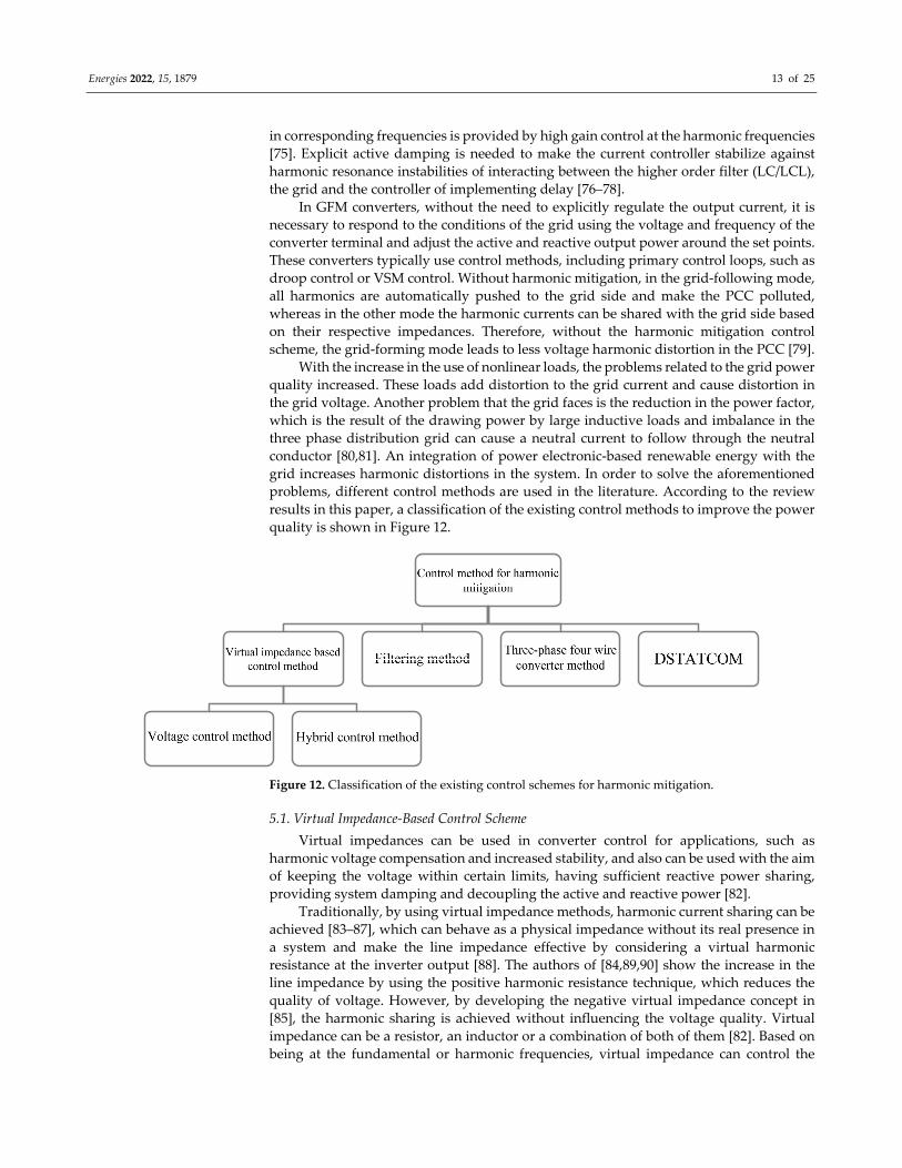
grid increases harmonic distortions in the system. In order to solve the aforementioned
problems, different control methods are used in the literature. According to the review
results in this paper, a classification of the existing control methods to improve the power
quality is shown in Figure 12.
Figure 12. Classification of the existing control schemes for harmonic mitigation.
5.1. Virtual Impedance‐Based Control Scheme
Virtual impedances can be used in converter control for applications, such as
harmonic voltage compensation and increased stability, and also can be used with the aim
of keeping the voltage within certain limits, having sufficient reactive power sharing,
providing system damping and decoupling the active and reactive power [82].
Traditionally, by using virtual impedance methods, harmonic current sharing can be
achieved [83–87], which can behave as a physical impedance without its real presence in
a system and make the line impedance effective by considering a virtual harmonic
resistance at the inverter output [88]. The authors of [84,89,90] show the increase in the
line impedance by using the positive harmonic resistance technique, which reduces the
quality of voltage. However, by developing the negative virtual impedance concept in
[85], the harmonic sharing is achieved without influencing the voltage quality. Virtual
impedance can be a resistor, an inductor or a combination of both of them [82]. Based on
being at the fundamental or harmonic frequencies, virtual impedance can control the
Energies 2022, 15, 1879 14 of 25
power flow and grid disturbance ride through or active damping and harmonic
mitigation, respectively [79].
In this section, various control schemes based on virtual impedance are discussed.
5.1.1. Current Control Method (CCM)
Harmonic compensation in grid‐connected renewable energy sources can be realized
by using the CCM [91–93]. In this control method, the current line is controlled based on
the modified current reference, which is modified according to the harmonic
compensation requirement and the inverter available power rating [79]. To achieve the
purpose of PCC voltage harmonic mitigation, the converter side is controlled to operate
as a small damping resistor at the selected harmonic frequencies. Therefore, more
harmonic currents of nonlinear loads are absorbed by the converter side and the grid
mainly provides sinusoidal fundamental current. As a result, the harmonic distortion of
the PCC voltage is improved [91,94].
5.1.2. Voltage Control Method (VCM)
The VCM‐based control method can be used in both grid‐connected and islanded
modes. By using a virtual harmonic impedance control, the VCM can obtain a reliable
PCC harmonic mitigation. In order to track the voltage reference, a double loop voltage
controller is generally incorporated, with the PR controller in the outer loop, to control the
voltage of the filter capacitor. By adding a feed‐forward term of a harmonic voltage
reference, the voltage reference is modified [95].
The VCM and hybrid control method (HCM), which can be innovative control
methods, are used as grid‐forming converters for harmonic mitigation.
5.1.3. Hybrid Control Method (HCM)
Due to the limitations of conventional CCM and VCM, the HCM has been presented
in the literature.
Using dead time between the switches of the leg of the inverter will cause output
voltage harmonics in a low frequency range. As the impedance of the grid is low at a low
frequency, the small output voltage harmonics can cause a serious distortion of the
injected grid current. In [96], to improve the injected grid current quality, a virtual series
impedance in order to increase the output impedance is used. Additionally, to not affect
the dynamic performance, this virtual impedance is designed to be high just at harmonic
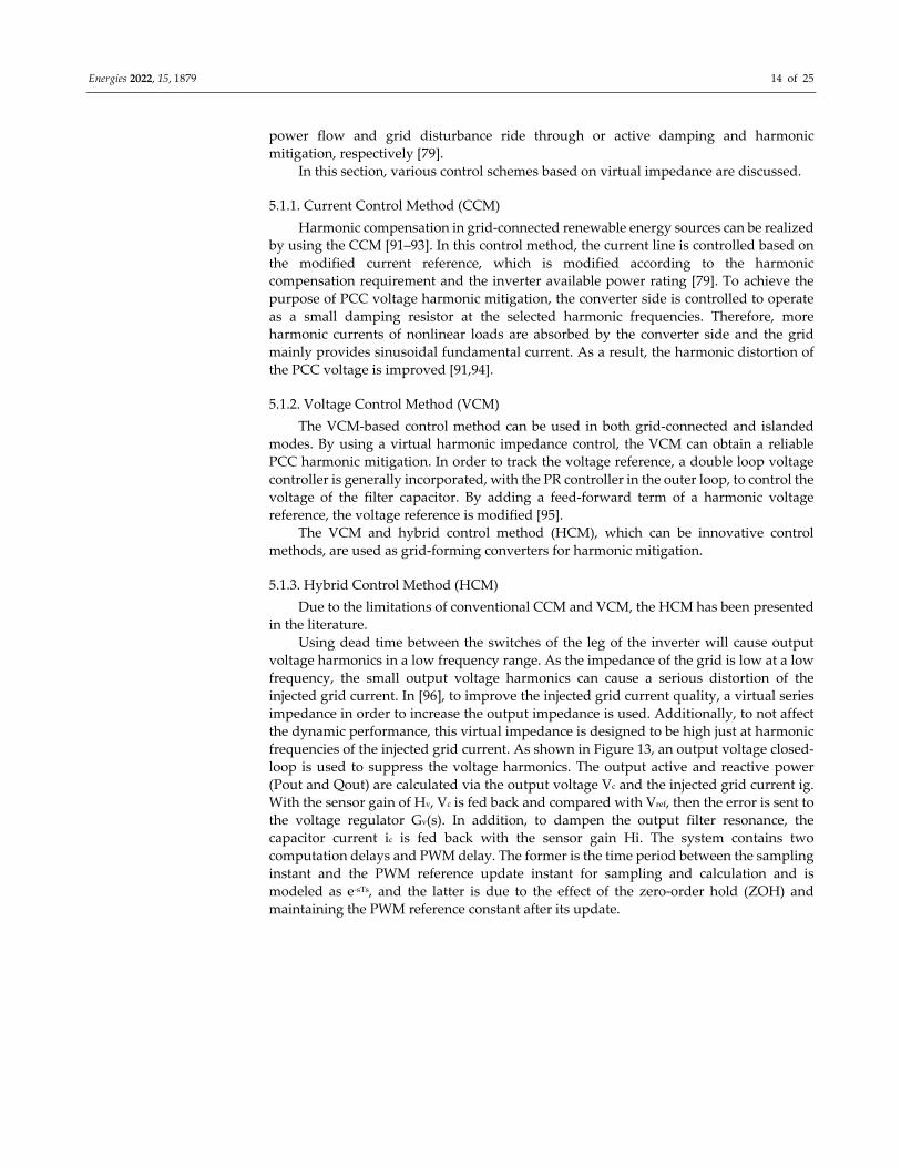
frequencies of the injected grid current. As shown in Figure 13, an output voltage closed‐
loop is used to suppress the voltage harmonics. The output active and reactive power
(Pout and Qout) are calculated via the output voltage Vc and the injected grid current ig.
With the sensor gain of Hv, Vc is fed back and compared with Vref, then the error is sent to
the voltage regulator Gv(s). In addition, to dampen the output filter resonance, the
capacitor current ic is fed back with the sensor gain Hi. The system contains two
computation delays and PWM delay. The former is the time period between the sampling
instant and the PWM reference update instant for sampling and calculation and is
modeled as e‐sTs, and the latter is due to the effect of the zero‐order hold (ZOH) and
maintaining the PWM reference constant after its update.
Energies 2022, 15, 1879 15 of 25
P&Qcontrol
Grid
V
Hv
Gv(s)
Hi
ZOH
PWM
Vm
C
e-sTs
ref
Figure 13. Structure of the voltage‐controlled grid‐connected converter [96].
With reducing the inertia of the power system in grid‐connected renewable energy
sources, which affects the frequency and voltage and even causes system instability, the
virtual synchronous generator (VSG) control method to solve the inertia shortage and
frequency fluctuation is proposed [97–99]. This method, by imitating the primary power
regulation and primary frequency regulating behavior of the synchronous generator,
creates inertial support for the grid. Since most of the renewable energy sources are
located in remote areas, they are weakly connected to the grid. Therefore, using the VSG
method, an oscillation or interaction between VSG and the grid is created and the power
quality of VSG is affected by the distorted grid voltage. Thus, to mitigate the current
harmonics, the harmonic impedance of the converter can be reshaped [100,101].
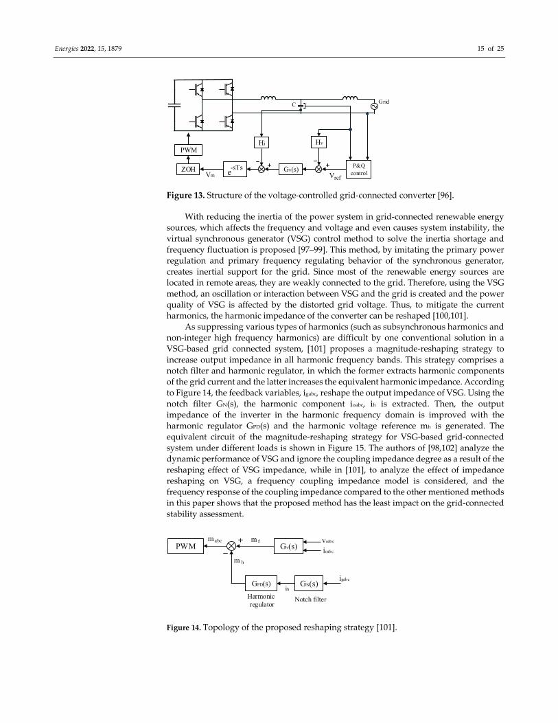
As suppressing various types of harmonics (such as subsynchronous harmonics and
non‐integer high frequency harmonics) are difficult by one conventional solution in a
VSG‐based grid connected system, [101] proposes a magnitude‐reshaping strategy to
increase output impedance in all harmonic frequency bands. This strategy comprises a
notch filter and harmonic regulator, in which the former extracts harmonic components
of the grid current and the latter increases the equivalent harmonic impedance. According
to Figure 14, the feedback variables, igabc, reshape the output impedance of VSG. Using the
notch filter GN(s), the harmonic component ioabc, ih is extracted. Then, the output
impedance of the inverter in the harmonic frequency domain is improved with the
harmonic regulator GPD(s) and the harmonic voltage reference mh is generated. The
equivalent circuit of the magnitude‐reshaping strategy for VSG‐based grid‐connected
system under different loads is shown in Figure 15. The authors of [98,102] analyze the
dynamic performance of VSG and ignore the coupling impedance degree as a result of the
reshaping effect of VSG impedance, while in [101], to analyze the effect of impedance
reshaping on VSG, a frequency coupling impedance model is considered, and the
frequency response of the coupling impedance compared to the other mentioned methods
in this paper shows that the proposed method has the least impact on the grid‐connected
stability assessment.
PWM Gv(s)
GPD(s) GN(s)
Harmonic regulator
Notch filter
voabc
ioabc
igabc
ih
mabc m f
m h
Figure 14. Topology of the proposed reshaping strategy [101].
Energies 2022, 15, 1879 16 of 25
GridInverter
Zg_hZvir_hZinv_h
DifferentLoads
Harmonic current
Figure 15. Equivalent circuit of magnitude‐reshaping strategy for the VSG‐based grid‐
connected system under different loads [101].
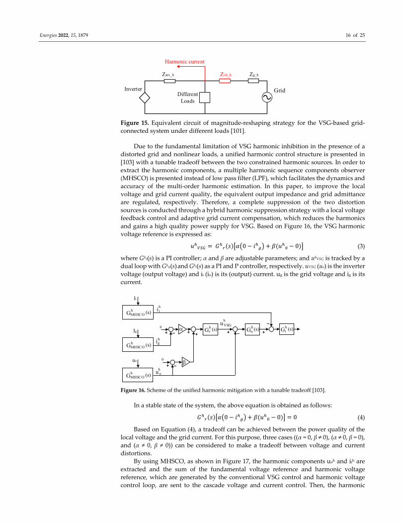
Due to the fundamental limitation of VSG harmonic inhibition in the presence of a
distorted grid and nonlinear loads, a unified harmonic control structure is presented in
[103] with a tunable tradeoff between the two constrained harmonic sources. In order to
extract the harmonic components, a multiple harmonic sequence components observer
(MHSCO) is presented instead of low pass filter (LPF), which facilitates the dynamics and
accuracy of the multi‐order harmonic estimation. In this paper, to improve the local
voltage and grid current quality, the equivalent output impedance and grid admittance
are regulated, respectively. Therefore, a complete suppression of the two distortion
sources is conducted through a hybrid harmonic suppression strategy with a local voltage
feedback control and adaptive grid current compensation, which reduces the harmonics
and gains a high quality power supply for VSG. Based on Figure 16, the VSG harmonic
voltage reference is expressed as:
𝑢 𝐺 𝑠 𝛼 0 𝑖 𝛽 𝑢 0 (3)
where Ghr(s) is a PI controller; α and β are adjustable parameters; and uhVSG is tracked by a
dual loop with Ghu(s) and Ghi(s) as a PI and P controller, respectively. uVSG (uo) is the inverter
voltage (output voltage) and ii (io) is its (output) current. ug is the grid voltage and ig is its
current.
Ii
Ig
uo
0
0
Gih (s)Gr
h (s)
GMHSCOh (s)
GMHSCOh (s)
GMHSCOh (s)
iih
igh
u oh
Guh (s)
uVSGh
Figure 16. Scheme of the unified harmonic mitigation with a tunable tradeoff [103].
In a stable state of the system, the above equation is obtained as follows:
𝐺 𝑠 𝛼 0 𝑖 𝛽 𝑢 0 0 (4)
Based on Equation (4), a tradeoff can be achieved between the power quality of the
local voltage and the grid current. For this purpose, three cases ((α = 0, β ≠ 0), (α ≠ 0, β = 0),
and (α ≠ 0, β ≠ 0)) can be considered to make a tradeoff between voltage and current
distortions.
By using MHSCO, as shown in Figure 17, the harmonic components uoh and iih are
extracted and the sum of the fundamental voltage reference and harmonic voltage
reference, which are generated by the conventional VSG control and harmonic voltage
control loop, are sent to the cascade voltage and current control. Then, the harmonic
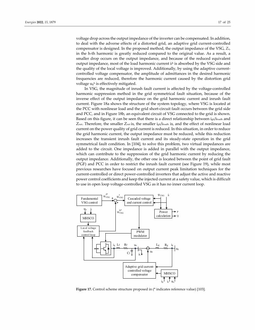
Energies 2022, 15, 1879 17 of 25
voltage drop across the output impedance of the inverter can be compensated. In addition,
to deal with the adverse effects of a distorted grid, an adaptive grid current‐controlled
compensator is designed. In the proposed method, the output impedance of the VSG, Zo,
in the h‐th harmonic is greatly reduced compared to the original value. As a result, a
smaller drop occurs on the output impedance, and because of the reduced equivalent
output impedance, most of the load harmonic current ilh is absorbed by the VSG side and
the quality of the local voltage is improved. Additionally, by using the adaptive current‐
controlled voltage compensator, the amplitude of admittances in the desired harmonic
frequencies are reduced, therefore the harmonic current caused by the distortion grid
voltage ugh is effectively mitigated.
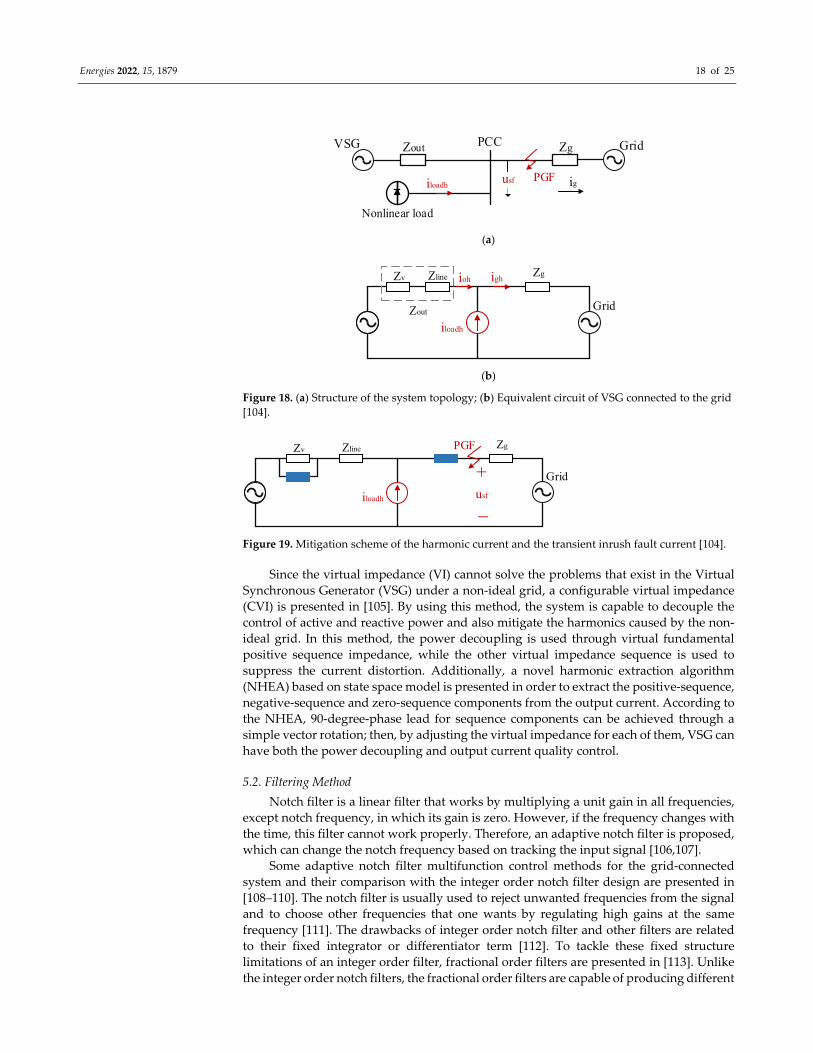
In VSG, the magnitude of inrush fault current is affected by the voltage‐controlled
harmonic suppression method in the grid symmetrical fault situation, because of the
inverse effect of the output impedance on the grid harmonic current and inrush fault
current. Figure 18a shows the structure of the system topology, where VSG is located at
the PCC with nonlinear load and the grid short‐circuit fault occurs between the grid side
and PCC, and in Figure 18b, an equivalent circuit of VSG connected to the grid is shown.
Based on this figure, it can be seen that there is a direct relationship between igh/iloadh and
Zout. Therefore, the smaller Zout is, the smaller igh/iloadh is, and the effect of nonlinear load
current on the power quality of grid current is reduced. In this situation, in order to reduce
the grid harmonic current, the output impedance must be reduced, while this reduction
increases the transient inrush fault current and its steady‐state operation in the grid
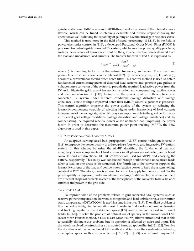
symmetrical fault condition. In [104], to solve this problem, two virtual impedances are
added to the circuit. One impedance is added in parallel with the output impedance,
which can contribute to the suppression of the grid harmonic current by reducing the
output impedance. Additionally, the other one is located between the point of grid fault
(PGF) and PCC in order to restrict the inrush fault current (see Figure 19), while most
previous researches have focused on output current peak limitation techniques for the
current‐controlled or direct power‐controlled inverters that adjust the active and reactive
power control coefficients and keep the injected current at a safety value, which is difficult
to use in open loop voltage‐controlled VSG as it has no inner current loop.
iL
Lf Rf Lg Rg
Cfuc
ig
ug
Power calculation Q
P
u iiVSG
Cascaded voltage and current control
uVSG*uVSG
f*
Fundamental VSG control
PWM modulator
MHSCO
Local voltage feedback
control loop
u iiouVSG
h*
ig uo
MHSCO
Adaptive grid current-controlled voltage
compensator
uic cig Figure 17. Control scheme structure proposed in (* indicates reference value) [103].
Energies 2022, 15, 1879 18 of 25
GridPCC ZgVSG Zout
iloadh igusf PGF
Nonlinear load
(a)
Grid
ZgZline
iloadh
ighioh
Zout
Zv
(b)
Figure 18. (a) Structure of the system topology; (b) Equivalent circuit of VSG connected to the grid
[104].
Grid
ZgZline
iloadh
Zv PGF
usf
+
_
Figure 19. Mitigation scheme of the harmonic current and the transient inrush fault current [104].
Since the virtual impedance (VI) cannot solve the problems that exist in the Virtual
Synchronous Generator (VSG) under a non‐ideal grid, a configurable virtual impedance
(CVI) is presented in [105]. By using this method, the system is capable to decouple the
control of active and reactive power and also mitigate the harmonics caused by the non‐
ideal grid. In this method, the power decoupling is used through virtual fundamental
positive sequence impedance, while the other virtual impedance sequence is used to
suppress the current distortion. Additionally, a novel harmonic extraction algorithm
(NHEA) based on state space model is presented in order to extract the positive‐sequence,
negative‐sequence and zero‐sequence components from the output current. According to
the NHEA, 90‐degree‐phase lead for sequence components can be achieved through a
simple vector rotation; then, by adjusting the virtual impedance for each of them, VSG can
have both the power decoupling and output current quality control.
5.2. Filtering Method
Notch filter is a linear filter that works by multiplying a unit gain in all frequencies,
except notch frequency, in which its gain is zero. However, if the frequency changes with
the time, this filter cannot work properly. Therefore, an adaptive notch filter is proposed,
which can change the notch frequency based on tracking the input signal [106,107].
Some adaptive notch filter multifunction control methods for the grid‐connected
system and their comparison with the integer order notch filter design are presented in
[108–110]. The notch filter is usually used to reject unwanted frequencies from the signal
and to choose other frequencies that one wants by regulating high gains at the same
frequency [111]. The drawbacks of integer order notch filter and other filters are related
to their fixed integrator or differentiator term [112]. To tackle these fixed structure
limitations of an integer order filter, fractional order filters are presented in [113]. Unlike
the integer order notch filters, the fractional order filters are capable of producing different
Energies 2022, 15, 1879 19 of 25
gain terms between 0 db/decade and ±20/40 db and make the power of the integrator more
flexible, which can be tuned to obtain a desirable and precise response during the
operation as well as having the capability of gaining an asymmetrical gain response curve.
This method is used more in the field of signal processing [114,115]. In the field of
power electronics control, in [116], a developed Fractional Order Notch Filter (FNOF) is
proposed to control a grid connected PV system, which can solve power quality problems,
such as the existence of harmonic current on the grid side, reactive power demand from
the load and unbalanced load currents. The transfer function of FNOF is expressed as:
𝐺 𝜉𝜔𝑠
𝑠 𝜉𝜔𝑠 𝜔 (5)
where ξ is damping factor, ω is the natural frequency, and α and β are fractional
parameters, which are variable in the interval (0, 2). By considering α = β = 1, Equation (5)
becomes a conventional second order notch filter. This control method is used to obtain
fundamental current components of distorted load currents and generate gate pulses of
voltage source converter of the system to provide the required load active power from the
PV and mitigate the grid current harmonics distortion and compensating reactive power
and load unbalancing. In [117], to improve the power quality of three phase grid
connected PV system under different conditions (voltage distortion and voltage
unbalance), a new multiple improved notch filter (MINF) control algorithm is proposed.
This control algorithm improves the power quality of the system by reducing the
harmonic components (capable of rejecting higher order harmonics) of load currents
independent of the voltage signal, which plays an important role in the good performance
in different grid voltage conditions (voltage distortion and voltage unbalance) and, by
compensating the required reactive power of the nonlinear load, improving the power
factor. In order to determine the maximum power point tracking (MPPT), the P&O
algorithm is used in this paper.
5.3. Three‐Phase Four Wire Converter Method
An adaptive learning based back propagation (AL‐BP) control technique is used in
[118] to improve the power quality of a three‐phase four‐wire grid interactive PV‐battery
system. In this scheme, by using the AL‐BP algorithm, the fundamental real and
imaginary power components of load currents in all phases are extracted, and a boost
converter and a bidirectional DC–DC converter are used for MPPT and charging the
battery, respectively. This study was conducted through nonlinear and unbalanced loads
when a load on one phase is disconnected. The fourth leg of the converter supplies the
harmonic currents of the load and compensates reactive power to keep the system voltage
constant at PCC. Therefore, there is no need for a grid to supply harmonic current. So, the
power quality is improved under unbalanced loading conditions. In this situation, there
are different shapes of currents in each of the three phases of the converter to have balance
currents and power in the grid side.
5.4. DSTATCOM
To improve some of the problems related to grid‐connected VSC systems, such as
reactive power compensation, harmonics mitigation and load unbalancing, a distribution
static compensator (DSTATCOM) is used in some industries [119]. The salient problem of
this method is its high implementation cost. In order to find a solution based on learning
and tracking capability, the distributed sparse (DS) control method is used in different
fields. In [120], to solve the problem of optimal use of sparsity in the conventional LMS
(Least Mean Fourth) method, a LMF (Least Mean Fourth) filter is introduced that is able
to partially eliminate this problem, but its operation is affected by noise and input. This
drawback is solved by introducing a distributed based adaptive filter in [121,122]. To solve
the drawbacks of the conventional LMF method and improve the steady‐state behavior,
an adaptive sparse method is presented in [121,122]. In [123], a novel multipurpose DS
Energies 2022, 15, 1879 20 of 25
(Distributed Sparse) control approach is proposed for the grid‐connected PV system,
which can operate in different solar radiations and mitigate the harmonics of the loads
and create a balanced grid current. In the absence of access to solar radiation, the system
operates as a DSTATCOM using the same voltage source converter, which is cost effective.
6. Conclusions
The application of GFM converters is a promising solution to the problems of the
high penetration of converter‐interfaced renewable resources integrated into low‐inertia
grids. This paper explores various challenges related to GFM converters, including
frequency deviations, black start capability, angle stability, frequency stability, voltage
stability and harmonic mitigation. Moreover, various control schemes presented in the
current literature are reviewed. In terms of frequency deviation, the consequences of not
limiting the RoCoF in low‐inertia systems are discussed and several methods to limit
frequency deviation and increase the inertia of the power system, including synthetic
inertia and utilizing energy storage system, are summarized. The concept and phenomena
of the power system stability in modern power systems and stabilization strategies with
respect to different stability classes, including angle stability, frequency stability and
voltage stability, are discussed and we pointed out that the GFM converters are preferable
to GFL converters, especially in low‐inertia systems. Under large grid disturbances with
respect to the low current rate of switches in GFM converters, different control methods
to limit the overcurrent are explored. Additionally, regarding the voltage regulation
capability of these converters, several studies have analyzed their robust small signal
stability in weak grid conditions. In order to suppress various types of harmonics,
different control techniques, including virtual impedance‐based method, filtering
method, four‐wire converter method and DSTATCOM, are discussed.
7. Future Scope
While the GFM converter is an exciting new technology for grid integration of
renewable energy resources, there are a few challenges that are yet to be addressed for the
effective operation of the renewable rich power grid. This technology is not a “silver
bullet” that can solve all challenges in the power system. The thoughtful implementation
of this technology alongside other technologies and techniques needs to be critically
studied for managing the transition to renewables. The assessment of the cost–benefit
analysis is also important to evaluate the implementation of the GFM converters with
other technologies, such as synchronous condensers and GFL inverters. Although the
GFM converter helps the nearby GFL converter to operate stably, it is itself susceptible to
small signal instability due to the faster inner control loops. In‐depth studies are required
to investigate the use of the power system stabilizer (PSS) in the control facilities of the
GFM converters, which has been historically used in synchronous generators to manage
small signal stability. The construction of the exact definition of the new GFM converter
technology is complex, as its characteristics are quite similar to the synchronous
generators. To date, the grid codes for the GFM converters integration into the grid are
not mature, for example, the system operators/regulators are still not fully clear whether
this technology can be part of an asynchronous or synchronous generator type for
assessing its performance. Therefore, the grid codes need to be thoroughly studied to
facilitate the GFM converter technology implementation. Finally, a detailed study is
required to formulate the exact required number of GFM converters to replace the existing
GFL converters to ensure a secure system operation with minimum cost.
Author Contributions: conceptualization, E.B., M.R.I. and M.M.R.; methodology, E.B., M.R.I. and
M.M.R.; software, E.B.; validation, M.R.I. and M.M.R.; investigation, E.B. and M.R.I.; data curation,
E.B. and M.M.R.; writing—original draft preparation, E.B.; writing—review and editing, M.R.I.,
M.M.R. and K.M.M.; supervision, M.R.I., M.M.R. and K.M.M. All authors have read and agreed to
the published version of the manuscript.
Energies 2022, 15, 1879 21 of 25
Funding: This research received no external funding.
Institutional Review Board Statement: Not applicable.
Informed Consent Statement: Not applicable.
Data Availability Statement: Not applicable.
Conflicts of Interest: The authors declare no conflicts of interest.
References
1. Beza, M.; Bongiorno, M.; Narula, A. Impact of control loops on the passivity properties of grid‐forming converters with fault‐
ride through capability. Energies 2021, 14, 6036.
2. Ray, I. Review of impedance‐based analysis methods applied to grid‐forming inverters in inverter‐dominated grids. Energies
2021, 14, 2686.
3. Milano, F.; Dörfler, F.; Hug, G.; Hill, D.J.; Verbič, G. Foundations and challenges of low‐inertia systems. In Proceedings of the
2018 Power Systems Computation Conference (PSCC), Dublin, Ireland, 11–15 June 2018; pp. 1–25.
4. Hernández, J.C.; Bueno, P.G.; Sanchez‐Sutil, F. Enhanced utility‐scale photovoltaic units with frequency support functions and
dynamic grid support for transmission systems. IET Renew. Power Gener. 2017, 11, 361–372.
5. Pawar, B.; Batzelis, E.; Chakrabarti, S.; Pal, B.C. Grid‐forming control for solar PV systems with power reserves. IEEE Trans.
Sustain. Energy 2021, 12, 1947–1959.
6. Guo, C.; Yang, S.; Liu, W.; Zhao, C.; Hu, J. Small‐signal stability enhancement approach for VSC‐HVDC system under weak AC
grid conditions based on single‐input single‐output transfer function model. IEEE Trans. Power Deliv. 2020, 36, 1313–1323.
7. Lu, S.; Xu, Z.; Xiao, L.; Jiang, W.; Bie, X. Evaluation and enhancement of control strategies for VSC stations under weak grid
strengths. IEEE Trans. Power Syst. 2017, 33, 1836–1847.
8. Sun, D.; Liu, H.; Gao, S.; Wu, L.; Song, P.; Wang, X. Comparison of different virtual inertia control methods for inverter‐based
generators. J. Mod. Power Syst. Clean Energy 2020, 8, 768–777.
9. Kroposki, B.; Johnson, B.; Zhang, Y.; Gevorgian, V.; Denholm, P.; Hodge, B.‐M.; Hannegan, B. Achieving a 100% renewable grid:
Operating electric power systems with extremely high levels of variable renewable energy. IEEE Power Energy Mag. 2017, 15,
61–73.
10. Christensen, P.; Andersen, G.K.; Seidel, M.; Bolik, S.; Engelken, S.; Knueppel, T.; Krontiris, A.; Wuerflinger, K.; Bülo, T.; Jahn, J.
High Penetration of Power Electronic Interfaced Power Sources and the Potential Contribution of Grid Forming Converters; ENTSO‐E:
Brussels, Belgium, 2020.
11. Lin, Y.; Eto, J.H.; Johnson, B.B.; Flicker, J.D.; Lasseter, R.H.; Villegas Pico, H.N.; Seo, G.‐S.; Pierre, B.J.; Ellis, A. Research Roadmap
on Grid‐Forming Inverters; National Renewable Energy Laboratory (NREL): Golden, CO, USA, 2020.
12. Pattabiraman, D.; Lasseter, R.; Jahns, T. Comparison of grid following and grid forming control for a high inverter penetration
power system. In Proceedings of the 2018 IEEE Power & Energy Society General Meeting (PESGM), Portland, OR, USA, 5–10
August 2018; pp. 1–5.
13. Tayyebi, A.; Groß, D.; Anta, A.; Kupzog, F.; Dörfler, F. Frequency stability of synchronous machines and grid‐forming power
converters. IEEE J. Emerg. Sel. Top. Power Electron. 2020, 8, 1004–1018.
14. Pattabiraman, D.; Lasseter, R.H.; Jahns, T.M. Short‐term voltage stability of power systems with high inverter penetration under
small disturbances. In Proceedings of the 2019 IEEE Power & Energy Society General Meeting (PESGM), Atlanta, GA, USA, 4–
8 August 2019; pp. 1–5.
15. Unruh, P.; Nuschke, M.; Strauß, P.; Welck, F. Overview on grid‐forming inverter control methods. Energies 2020, 13, 2589.
16. Awal, M.; Yu, H.; Husain, I.; Yu, W.; Lukic, S.M. Selective harmonic current rejection for virtual oscillator controlled grid‐
forming voltage source converters. IEEE Trans. Power Electron. 2020, 35, 8805–8818.
17. Fang, J.; Li, H.; Tang, Y.; Blaabjerg, F. On the inertia of future more‐electronics power systems. IEEE J. Emerg. Sel. Top. Power
Electron. 2018, 7, 2130–2146.
18. Qi, Y.; Deng, H.; Liu, X.; Tang, Y. Synthetic inertia control of grid‐connected inverter considering the synchronization dynamics.
IEEE Trans. Power Electron. 2021, 37, 1411–1421.
19. Jiang, Y.; Bernstein, A.; Vorobev, P.; Mallada, E. Grid‐forming frequency shaping control. arXiv 2020, arXiv:2009.06707.
20. Zhang, W.; Remon, D.; Rodriguez, P. Frequency support characteristics of grid‐interactive power converters based on the
synchronous power controller. IET Renew. Power Gener. 2017, 11, 470–479.
21. Zhong, Q.‐C.; Nguyen, P.‐L.; Ma, Z.; Sheng, W. Self‐synchronized synchronverters: Inverters without a dedicated
synchronization unit. IEEE Trans. Power Electron. 2013, 29, 617–630.
22. Qi, Y.; Yang, T.; Fang, J.; Tang, Y.; Potti, K.R.R.; Rajashekara, K. Grid inertia support enabled by smart loads. IEEE Trans. Power
Electron. 2020, 36, 947–957.
23. Fang, J.; Tang, Y.; Li, H.; Li, X. A battery/ultracapacitor hybrid energy storage system for implementing the power management
of virtual synchronous generators. IEEE Trans. Power Electron. 2017, 33, 2820–2824.
24. Liu, H.; Zhang, C.; Peng, X.; Zhang, S. Configuration of an energy storage system for primary frequency reserve and inertia
response of the power grid. IEEE Access 2021, 9, 41965–41975.
Energies 2022, 15, 1879 22 of 25
25. Heydari, R.; Savaghebi, M.; Blaabjerg, F. Fast frequency control of low‐inertia hybrid grid utilizing extended virtual
synchronous machine. In Proceedings of the 2020 11th Power Electronics, Drive Systems, and Technologies Conference
(PEDSTC), Tehran, Iran, 4–6 February 2020; pp. 1–5.
26. Noris, L.; Rueda, J.; Rakhshani, E.; Korai, A.W. Power system black‐start and restoration with high share of power‐electronic
converters. In Proceedings of the 2019 IEEE Power & Energy Society General Meeting (PESGM), Atlanta, GA, USA, 4–8 August
2019; pp. 1–5.
27. Alassi, A.; Ahmed, K.; Egea‐Alvarez, A.; Ellabban, O. Performance evaluation of four grid‐forming control techniques with soft
black‐start capabilities. In Proceedings of the 2020 9th International Conference on Renewable Energy Research and Application
(ICRERA), Glasgow, UK, 27–30 September 2020; pp. 221–226.
28. Alassi, A.; Ahmed, K.; Egea‐Alvarez, A.; Foote, C. Modified grid‐forming converter control for black‐start and grid‐
synchronization applications. In Proceedings of the 2021 56th International Universities Power Engineering Conference (UPEC),
Middlesbrough, UK, 31 August–3 September 2021; pp. 1–5.
29. Korai, A.W.; Rakhshani, E.; Adabi, M.E.; Torres, J.L.R.; van der Meijden, M.A. Modelling and simulation of wind turbines with
grid forming direct voltage control and black‐start capability. In Modelling and Simulation of Power Electronic Converter Dominated
Power Systems in PowerFactory; Springer: Cham, Switzerland, 2021; pp. 245–268.
30. Shrestha, A.; Gonzalez‐Longatt, F. Frequency stability issues and research opportunities in converter dominated power system.
Energies 2021, 14, 4184.
31. Wang, X.; Chen, L.; Sun, D.; Zhang, L.; Nian, H. A modified self‐synchronized synchronverter in unbalanced power grids with
balanced currents and restrained power ripples. Energies 2019, 12, 923.
32. Kundur, P.; Paserba, J.; Ajjarapu, V.; Andersson, G.; Bose, A.; Cañizares, C.; Hatziargyriou, N.; Hill, D.; Stankovic, A.; Taylor,
C.; et al. Definition and classification of power system stability. IEEE Trans. Power Syst. 2004, 19, 1387–1401.
33. Power System Dynamic Performance Committee (PSDP). Stability Definitions and Characterization of Dynamic Behavior in Systems
with High Penetration of Power Electronic Interfaced Technologies; Technical Report PS‐TR77; IEEE PES: Piscataway, NJ, USA, 2020.
34. Taul, M.G.; Wang, X.; Davari, P.; Blaabjerg, F. An overview of assessment methods for synchronization stability of grid‐
connected converters under severe symmetrical grid faults. IEEE Trans. Power Electron. 2019, 34, 9655–9670.
35. Taul, M.G.; Wang, X.; Davari, P.; Blaabjerg, F. Current limiting control with enhanced dynamics of grid‐forming converters
during fault conditions. IEEE J. Emerg. Sel. Top. Power Electron. 2019, 8, 1062–1073.
36. Rosso, R.; Wang, X.; Liserre, M.; Lu, X.; Engelken, S. Grid‐forming converters: control approaches, grid‐synchronization, and
future trends—A review. IEEE Open J. Ind. Appl. 2021, 2, 93–109.
37. Denis, G.; Prevost, T.; Debry, M.S.; Xavier, F.; Guillaud, X.; Menze, A. The migrate project: The challenges of operating a
transmission grid with only inverter‐based generation. A grid‐forming control improvement with transient current‐limiting
control. IET Renew. Power Gener. 2018, 12, 523–529.
38. Huang, L.; Xin, H.; Wang, Z.; Zhang, L.; Wu, K.; Hu, J. Transient stability analysis and control design of droop‐controlled voltage
source converters considering current limitation. IEEE Trans. Smart Grid 2017, 10, 578–591.
39. Shi, K.; Song, W.; Xu, P.; Liu, R.; Fang, Z.; Ji, Y. Low‐voltage ride‐through control strategy for a virtual synchronous generator
based on smooth switching. IEEE Access 2017, 6, 2703–2711.
40. Wu, H.; Wang, X. Design‐oriented transient stability analysis of PLL‐synchronized voltage‐source converters. IEEE Trans. Power
Electron. 2019, 35, 3573–3589.
41. Shi, K.; Ye, H.; Xu, P.; Zhao, D.; Jiao, L. Low‐voltage ride through control strategy of virtual synchronous generator based on
the analysis of excitation state. IET Gener. Transm. Distrib. 2018, 12, 2165–2172.
42. Piya, P.; Ebrahimi, M.; Karimi‐Ghartemani, M.; Khajehoddin, S.A. Fault ride‐through capability of voltage‐controlled inverters.
IEEE Trans. Ind. Electron. 2018, 65, 7933–7943.
43. Lu, X.; Wang, J.; Guerrero, J.M.; Zhao, D. Virtual‐impedance‐based fault current limiters for inverter dominated AC microgrids.
IEEE Trans. Smart Grid 2016, 9, 1599–1612.
44. Shuai, Z.; Shen, C.; Liu, X.; Li, Z.; Shen, Z.J. Transient angle stability of virtual synchronous generators using Lyapunov’s direct
method. IEEE Trans. Smart Grid 2018, 10, 4648–4661.
45. Pan, D.; Wang, X.; Liu, F.; Shi, R. Transient stability of voltage‐source converters with grid‐forming control: A design‐oriented
study. IEEE J. Emerg. Sel. Top. Power Electron. 2019, 8, 1019–1033.
46. Wu, H.; Wang, X. Design‐oriented transient stability analysis of grid‐connected converters with power synchronization control.
IEEE Trans. Ind. Electron. 2018, 66, 6473–6482.
47. Bottrell, N.; Green, T.C. Comparison of current‐limiting strategies during fault ride‐through of inverters to prevent latch‐up
and wind‐up. IEEE Trans. Power Electron. 2013, 29, 3786–3797.
48. Chen, J.; Prystupczuk, F.; O’Donnell, T. Use of voltage limits for current limitations in grid‐forming converters. CSEE J. Power
Energy Syst. 2020, 6, 259–269.
49. Awal, M.; Husain, I. Transient stability assessment for current constrained and unconstrained fault ride‐through in virtual
oscillator controlled converters. IEEE J. Emerg. Sel. Top. Power Electron. 2021, 9, 6935–6946.
50. Rokrok, E.; Qoria, T.; Bruyere, A.; Francois, B.; Guillaud, X. Transient stability assessment and enhancement of grid‐forming
converters embedding current reference saturation as current limiting strategy. IEEE Trans. Power Syst. 2021.
https://doi.org/10.1109/TPWRS.2021.3107959.
Energies 2022, 15, 1879 23 of 25
51. Rosso, R.; Engelken, S.; Liserre, M. On the implementation of an FRT strategy for grid‐forming converters under symmetrical
and asymmetrical grid faults. IEEE Trans. Ind. Appl. 2021, 57, 4385–4397.
52. Qoria, T.; Gruson, F.; Colas, F.; Denis, G.; Prevost, T.; Guillaud, X. Critical clearing time determination and enhancement of
grid‐forming converters embedding virtual impedance as current limitation algorithm. IEEE J. Emerg. Sel. Top. Power Electron.
2019, 8, 1050–1061.
53. Me, S.P.; Zabihi, S.; Blaabjerg, F.; Bahrani, B. Adaptive virtual resistance for post‐fault oscillation damping with grid‐forming
control. IEEE Trans. Power Electron. 2021, 37, 3813–3824.
54. Wu, H.; Wang, X. A mode‐adaptive power‐angle control method for transient stability enhancement of virtual synchronous
generators. IEEE J. Emerg. Sel. Top. Power Electron. 2020, 8, 1034–1049.
55. Chen, M.; Zhou, D.; Blaabjerg, F. Enhanced transient angle stability control of grid‐forming converter based on virtual
synchronous generator. IEEE Trans. Ind. Electron. 2021. https://doi.org/10.1109/tie.2021.3114723.
56. Xiong, X.; Wu, C.; Cheng, P.; Blaabjerg, F. An optimal damping design of virtual synchronous generators for transient stability
enhancement. IEEE Trans. Power Electron. 2021, 36, 11026–11030.
57. Wang, X.; Blaabjerg, F. Harmonic stability in power electronic‐based power systems: Concept, modeling, and analysis. IEEE
Trans. Smart Grid 2018, 10, 2858–2870.
58. Huang, L.; Xin, H.; Yang, H.; Wang, Z.; Xie, H. Interconnecting very weak AC systems by multiterminal VSC‐HVDC links with
a unified virtual synchronous control. IEEE J. Emerg. Sel. Top. Power Electron. 2018, 6, 1041–1053.
59. Yang, C.; Huang, L.; Xin, H.; Ju, P. Placing grid‐forming converters to enhance small signal stability of PLL‐integrated power
systems. IEEE Trans. Power Syst. 2020, 36, 3563–3573.
60. Rosso, R.; Cassoli, J.; Buticchi, G.; Engelken, S.; Liserre, M. Robust stability analysis of LCL filter based synchronverter under
different grid conditions. IEEE Trans. Power Electron. 2018, 34, 5842–5853.
61. Rodríguez‐Cabero, A.; Roldán‐Pérez, J.; Prodanovic, M. Virtual impedance design considerations for virtual synchronous
machines in weak grids. IEEE J. Emerg. Sel. Top. Power Electron. 2019, 8, 1477–1489.
62. Baltas, G.N.; Lai, N.B.; Marin, L.; Tarraso, A.; Rodriguez, P. Grid‐forming power converters tuned through artificial intelligence
to damp subsynchronous interactions in electrical grids. IEEE Access 2020, 8, 93369–93379.
63. Anderson, P.M.; Farmer, R.G. Series Compensation of Power Systems; PBLSH: Encinitas, CA, USA, 1996.
64. Ebrahimzadeh, E.; Blaabjerg, F.; Wang, X.; Bak, C.L. Harmonic stability and resonance analysis in large PMSG‐based wind
power plants. IEEE Trans. Sustain. Energy 2018, 9, 12–23.
65. Yu, M.; Roscoe, A.J.; Booth, C.D.; Dyśko, A.; Ierna, R.; Zhu, J.; Urdal, H. Use of an inertia‐less Virtual Synchronous Machine
within future power networks with high penetrations of converters. In Proceedings of the Power Systems Computation
Conference (PSCC), Genoa, Italy, 20–24 June 2016.
66. Roscoe, A.J.; Yu, M.; Dyśko, A.; Booth, C.; Ierna, R.; Zhu, J.; Urdal, H. A VSM (virtual synchronous machine) convertor control
model suitable for RMS studies for resolving system operator/owner challenges. In Proceedings of the 15th Wind Integration
Workshop, Vienna, Austria, 15–17 November 2016.
67. Li, G.; Chen, Y.; Luo, A.; He, Z.; Wang, H.; Zhu, Z.; Wu, W.; Zhou, L. Analysis and mitigation of subsynchronous resonance in
series‐compensated grid‐connected system controlled by a virtual synchronous generator. IEEE Trans. Power Electron. 2020, 35,
11096–11107.
68. Liao, Y.; Wang, X.; Liu, F.; Xin, K.; Liu, Y. Sub‐synchronous control interaction in grid‐forming VSCs with droop control. In
Proceedings of the 2019 4th IEEE Workshop on the Electronic Grid (eGRID), Xiamen, China, 11–14 November 2019; pp. 1–6.
69. Lai, N.B.; Baltas, G.N.; Rodriguez, P. Multi‐rotor virtual machine for grid‐forming converter to damp sub‐synchronous
resonances. IEEE Access 2021, 9, 128178–128187.
70. Peng, Y.; Wang, Y.; Liu, Y.; Yu, P.; Shu, S.; Lei, W. A full sequence impedance modelling and stability analysis of the virtual
synchronous generator with inner loops. IET Renew. Power Gener. 2021, 15, 397–408.
71. Zhang, X.; Zhanga, H.; Li, M.; Guo, Z.; Hu, Y.; Chen, Q.; Liu, X.; Lib, F. Analysis of dynamic power angle oscillation and its
suppression strategy for the droop‐controlled grid‐connected inverter. IEEE J. Emerg. Sel. Top. Power Electron. 2021, 9, 5718–5731.
72. Wang, F.; Zhang, L.; Feng, X.; Guo, H. An adaptive control strategy for virtual synchronous generator. IEEE Trans. Ind. Appl.
2018, 54, 5124–5133.
73. Li, C.; Yang, Y.; Cao, Y.; Wang, L.; Dragicevic, T.; Blaabjerg, F. Frequency and voltage stability analysis of grid‐forming virtual
synchronous generator attached to weak grid. IEEE J. Emerg. Sel. Top. Power Electron. 2020.
https://doi.org/10.1109/jestpe.2020.3041698.
74. Matevosyan, J.; Badrzadeh, B.; Prevost, T.; Quitmann, E.; Ramasubramanian, D.; Urdal, H.; Achilles, S.; MacDowell, J.; Huang,
S.H.; Vital, V. Grid‐forming inverters: Are they the key for high renewable penetration? IEEE Power Energy Mag. 2019, 17, 89–
98.
75. Zhou, K.; Yang, Y.; Blaabjerg, F.; Wang, D. Optimal selective harmonic control for power harmonics mitigation. IEEE Trans. Ind.
Electron. 2014, 62, 1220–1230.
76. Awal, M.; Husain, I.; Yu, W. Predictive current control for stabilizing power electronics based AC power systems. In
Proceedings of the 2017 IEEE Energy Conversion Congress and Exposition (ECCE), Cincinnati, OH, USA, 1–5 October 2017; pp.
4634–4641.
Energies 2022, 15, 1879 24 of 25
77. Awal, M.; Yu, H.; Della Flora, L.; Yu, W.; Lukic, S.; Husain, I. Observer based admittance shaping for resonance damping in
voltage source converters with LCL filter. In Proceedings of the 2019 IEEE Energy Conversion Congress and Exposition (ECCE),
Baltimore, MD, USA, 29 September–3 October 2019; pp. 4455–4462.
78. Awal, M.; Yu, W.; Husain, I. Passivity‐based predictive‐resonant current control for resonance damping in LCL‐equipped VSCs.
IEEE Trans. Ind. Appl. 2019, 56, 1702–1713.
79. Liang, X.; Andalib‐Bin‐Karim, C. Harmonics and mitigation techniques through advanced control in grid‐connected renewable
energy sources: A review. IEEE Trans. Ind. Appl. 2018, 54, 3100–3111.
80. Mukundan, N.; Singh, Y.; Naqvi, S.B.Q.; Singh, B.; Pychadathil, J. Multi‐objective solar power conversion system with MGI
control for grid integration at adverse operating conditions. IEEE Trans. Sustain. Energy 2020, 11, 2901–2910.
81. Barragán‐Villarejo, M.; Mauricio, J.M.; Olives‐Camps, J.C.; Matas‐Díaz, F.J.; de Paula García‐López, F.; Maza‐Ortega, J.M.
Harmonic and Imbalance Compensation in Grid‐Forming VSC. In Proceedings of the 2020 IEEE International Conference on
Industrial Technology (ICIT), Buenos Aires, Argentina, 26–28 February 2020; pp. 757–762.
82. Munir, S.; Li, Y.W. Residential distribution system harmonic compensation using PV interfacing inverter. IEEE Trans. Smart
Grid 2013, 4, 816–827.
83. Han, Y.; Shen, P.; Zhao, X.; Guerrero, J.M. An enhanced power sharing scheme for voltage unbalance and harmonics
compensation in an islanded AC microgrid. IEEE Trans. Energy Convers. 2016, 31, 1037–1050.
84. De, D.; Ramanarayanan, V. Decentralized parallel operation of inverters sharing unbalanced and nonlinear loads. IEEE Trans.
Power Electron. 2010, 25, 3015–3025.
85. Sreekumar, P.; Khadkikar, V. A new virtual harmonic impedance scheme for harmonic power sharing in an islanded microgrid.
IEEE Trans. Power Deliv. 2015, 31, 936–945.
86. Chen, J.; Wang, L.; Diao, L.; Du, H.; Liu, Z. Distributed auxiliary inverter of urban rail train—Load sharing control strategy
under complicated operation condition. IEEE Trans. Power Electron. 2015, 31, 2518–2529.
87. Han, H.; Hou, X.; Yang, J.; Wu, J.; Su, M.; Guerrero, J.M. Review of power sharing control strategies for islanding operation of
AC microgrids. IEEE Trans. Smart Grid 2015, 7, 200–215.
88. Sreekumar, P.; Khadkikar, V. Direct control of the inverter impedance to achieve controllable harmonic sharing in the islanded
microgrid. IEEE Trans. Ind. Electron. 2016, 64, 827–837.
89. Guerrero, J.M.; Matas, J.; de Vicuna, L.G.; Castilla, M.; Miret, J. Decentralized control for parallel operation of distributed
generation inverters using resistive output impedance. IEEE Trans. Ind. Electron. 2007, 54, 994–1004.
90. Vandoorn, T.; Meersman, B.; De Kooning, J.; Vandevelde, L. Controllable harmonic current sharing in islanded microgrids: DG
units with programmable resistive behavior toward harmonics. IEEE Trans. Power Deliv. 2012, 27, 831–841.
91. Li, Y.W.; He, J. Distribution system harmonic compensation methods: An overview of DG‐interfacing inverters. IEEE Ind.
Electron. Mag. 2014, 8, 18–31.
92. Teodorescu, R.; Blaabjerg, F.; Liserre, M. Proportional‐resonant controllers. A new breed of controllers suitable for grid‐
connected voltage‐source converters. J. Electr. Eng. 2006, 6, 6.
93. Pogaku, N.; Green, T. Harmonic mitigation throughout a distribution system: A distributed‐generator‐based solution. IEE Proc.‐
Gener. Transm. Distrib. 2006, 153, 350–358.
94. He, J.; Li, Y.W. Generalized microgrid harmonic compensation strategies using DG unit interfacing converters. In Proceedings
of the IECON 2012—38th Annual Conference on IEEE Industrial Electronics Society, Montreal, QC, Canada, 25–28 October 2012;
pp. 3419–3424.
95. He, J.; Li, Y.W.; Munir, M.S. A flexible harmonic control approach through voltage‐controlled DG–grid interfacing converters.
IEEE Trans. Ind. Electron. 2011, 59, 444–455.
96. Chen, X.; Ruan, X.; Yang, D.; Zhao, W.; Jia, L. Injected grid current quality improvement for a voltage‐controlled grid‐connected
inverter. IEEE Trans. Power Electron. 2017, 33, 1247–1258.
97. Lou, G.; Yang, Q.; Gu, W.; Zhang, J. An improved control strategy of virtual synchronous generator under symmetrical grid
voltage sag. Int. J. Electr. Power Energy Syst. 2020, 121, 106093.
98. Wu, H.; Ruan, X.; Yang, D.; Chen, X.; Zhao, W.; Lv, Z.; Zhong, Q.‐C. Small‐signal modeling and parameters design for virtual
synchronous generators. IEEE Trans. Ind. Electron. 2016, 63, 4292–4303.
99. Zhong, Q.‐C.; Weiss, G. Synchronverters: Inverters that mimic synchronous generators. IEEE Trans. Ind. Electron. 2010, 58, 1259–
1267.
100. Sun, J. Impedance‐based stability criterion for grid‐connected inverters. IEEE Trans. Power Electron. 2011, 26, 3075–3078.
101. Yang, W.; Wang, M.; Aziz, S.; Kharal, A.Y. Magnitude‐reshaping strategy for harmonic suppression of VSG‐based inverter
under weak grid. IEEE Access 2020, 8, 184399–184413.
102. Asrari, A.; Mustafa, M.; Ansari, M.; Khazaei, J. Impedance analysis of virtual synchronous generator‐based vector controlled
converters for weak AC grid integration. IEEE Trans. Sustain. Energy 2019, 10, 1481–1490.
103. Lou, G.; Yang, Q.; Gu, W.; Quan, X.; Guerrero, J.M.; Li, S. Analysis and design of hybrid harmonic suppression scheme for VSG
considering nonlinear loads and distorted grid. IEEE Trans. Energy Convers. 2021, 36, 3096–3107.
104. Zhou, L.; Liu, S.; Chen, Y.; Yi, W.; Wang, S.; Zhou, X.; Wu, W.; Zhou, J.; Xiao, C.; Liu, A. Harmonic current and inrush fault
current coordinated suppression method for VSG under non‐ideal grid condition. IEEE Trans. Power Electron. 2020, 36, 1030–
1042.
Energies 2022, 15, 1879 25 of 25
105. Hu, Y.; Shao, Y.; Yang, R.; Long, X.; Chen, G. A configurable virtual impedance method for grid‐connected virtual synchronous
generator to improve the quality of output current. IEEE J. Emerg. Sel. Top. Power Electron. 2019, 8, 2404–2419.
106. Mojiri, M.; Karimi‐Ghartemani, M.; Bakhshai, A. Time‐domain signal analysis using adaptive notch filter. IEEE Trans. Signal
Processing 2006, 55, 85–93.
107. Ketabi, A.; Farshadnia, M.; Malekpour, M.; Feuillet, R. A new control strategy for active power line conditioner (APLC) using
adaptive notch filter. Int. J. Electr. Power Energy Syst. 2013, 47, 31–40.
108. Chilipi, R.S.R.; Al Sayari, N.; Al Hosani, K.H.; Beig, A.R. Adaptive notch filter‐based multipurpose control scheme for grid‐
interfaced three‐phase four‐wire DG inverter. IEEE Trans. Ind. Appl. 2017, 53, 4015–4027.
109. Singh, B.; Kant, K.; Arya, S.R. Notch filter‐based fundamental frequency component extraction to control distribution static
compensator for mitigating current‐related power quality problems. IET Power Electron. 2015, 8, 1758–1766.
110. Kewat, S.; Singh, B. Modified amplitude adaptive control algorithm for power quality improvement in multiple distributed
generation system. IET Power Electron. 2019, 12, 2321–2329.
111. Schaumann, R.; Mac Elwyn Van Valkenburg, X.; Xiao, H. Design of Analog Filters; Oxford University Press: New York, NY, USA,
2001; Volume 1.
112. Radwan, A.G.; Elwakil, A.S.; Soliman, A.M. On the generalization of second‐order filters to the fractional‐order domain. J.
Circuits Syst. Comput. 2009, 18, 361–386.
113. Adhikary, A.; Sen, S.; Biswas, K. Practical realization of tunable fractional order parallel resonator and fractional order filters.
IEEE Trans. Circuits Syst. I Regul. Pap. 2016, 63, 1142–1151.
114. Ahmadi, P.; Maundy, B.; Elwakil, A.S.; Belostotski, L. High‐quality factor asymmetric‐slope band‐pass filters: A fractional‐order
capacitor approach. IET Circuits Devices Syst. 2012, 6, 187–197.
115. Bošković, M.; Šekara, T.B.; Rapaić, M.R.; Lutovac, B.; Daković, M.; Govedarica, V. Novel band‐pass and notch filter with
dynamic damping of fractional order. In Proceedings of the 2017 25th Telecommunication Forum (TELFOR), Belgrade, Serbia,
21–22 November 2017; pp. 1–4.
116. Badoni, M.; Singh, A.; Pandey, S.; Singh, B. Fractional order notch filter for grid‐connected solar pv system with power quality
improvement. IEEE Trans. Ind. Electron. 2021, 69, 429–439.
117. Jain, V.; Singh, B. A multiple improved notch filter‐based control for a single‐stage PV system tied to a weak grid. IEEE Trans.
Sustain. Energy 2018, 10, 238–247.
118. Kalla, U.K.; Kaushik, H.; Singh, B.; Kumar, S. Adaptive control of voltage source converter based scheme for power quality
improved grid‐interactive solar PV–battery system. IEEE Trans. Ind. Appl. 2019, 56, 787–799.
119. Singh, B.; Chandra, A.; Al‐Haddad, K. Power Quality: Problems and Mitigation Techniques; John Wiley & Sons: Hoboken, NJ, USA,
2014.
120. Lopes, C.G.; Sayed, A.H. Diffusion least‐mean squares over adaptive networks. In Proceedings of the 2007 IEEE International
Conference on Acoustics, Speech and Signal Processing‐ICASSP’07, Honolulu, HI, USA, 15–20 April 2007; pp. III‐917–III‐920.
121. Sayed, A.H.; Lopes, C.G. Distributed processing over adaptive networks. In Proceedings of the 2007 9th International
Symposium on Signal Processing and Its Applications, Sharjah, United Arab Emirates, 12–15 February 2007; pp. 1–3.
122. Hajiabadi, M.; Zamiri‐Jafarian, H. Distributed adaptive LMF algorithm for sparse parameter estimation in Gaussian mixture
noise. In Proceedings of the 7’th International Symposium on Telecommunications (IST’2014), Tehran, Iran, 9–11 September
2014; pp. 1046–1049.
123. Singh, A.K.; Kumar, S.; Singh, B. Solar PV energy generation system interfaced to three phase grid with improved power quality.
IEEE Trans. Ind. Electron. 2019, 67, 3798–3808.