
AVIO: Detecting Atomicity Violations via Access-Interleaving Invariants
Upload
independentCategory
view
0download
0
Interleaving Quasi-Sliding Mode Control of Parallel-Connected Inverters
D. Biel, E. Fossas, F. Guinjoan and R. Ramos Universitat Politècnica de Catalunya (UPC)
biel,guinjoan,[email protected], enric. [email protected]
Abstract An interleaving fixed switching frequency quasi-sliding control algorithm based on the Zero Average Dynamics (ZAD) approach is reported and applied to the design of a modular system of parallel-connected single-phase inverters. This approach is used in a laboratory prototype of three inverters with an FPGA control-based implementation embedding this algorithm. Experimental results are provided to illustrate the design features in terms of AC output voltage regulation, balanced current sharing among mismatched modules, interleaved fixed switching frequency operation and robustness with respect to load variations. 1. Introduction
This work focuses on the control of a modular DC-AC power conversion system comprising m single-phase inverter modules whose outputs are parallel-connected to the load. This power conversion structure exhibits the following features improving power management flexibility and reliability:
a) System power can be easily increased by parallel connecting additional inverter modules to the power conversion structure.
b) For a fixed power capability, device stresses can be reduced by adding inverter modules since the power density handled by each module is reduced.
c) The modular power conversion structure is especially well suited to benefit from the advantages of fixed-frequency interleaving operation mode such as the reduction in switching losses and output current ripple.
The control design of such modular inverter system must ensure both fast AC output voltage regulation with respect to input voltage and load transients and appropriate power sharing among active inverters, by controlling each inverter current. In addition, operation at a fixed switching frequency rate is desirable since it facilitates the design of filter elements and allows both control of switching losses and implementation of interleaving modulation. Several control strategies can be applied to achieve output voltage regulation and balanced current sharing among active inverter modules [1-7]. For instance, the master-slave technique is based on the design of a master inverter voltage loop ensuring tracking of the desired sinusoidal voltage reference and of as many
current loops as slave inverters, which are in charge of tracking master inverter current. The common approach to the design of the corresponding controllers generally assumes a fixed-frequency Pulse Width Modulation (PWM) operation and applies standard linear control techniques on a linear model of the inverter system. In consequence, the resulting linear controllers are model-dependent, this leading to output waveforms sensitive to inverter system parameter variations, as in the case of module mismatching. It must be pointed out that in the area of modular DC-DC power conversion; several authors have proposed the use of more sophisticated techniques, such as robust control or H∞ control, to overcome these problems. However, this generally results in high order controllers and the need for numerical algorithms to design controller coefficients [2,5].
In order to tackle the model dependence problem of PWM-based linear control, this work proposes a fixed switching-frequency quasi-sliding mode control approach for inverter system control design. This choice is motivated by the fact that quasi-sliding mode control preserves the robustness properties of its sliding mode control counterpart with respect to inverter system parameter variations. Moreover, unlike the sliding mode control approach, this technique also ensures a fixed switching frequency operation, and allows the implementation of interleaving algorithms. In this regard, this work has selected the algorithm based on the Zero Averaged Dynamics (ZAD) approach, whose robustness properties are described in [8], among the quasi-sliding control algorithms reported in the literature in the framework of single inverters control [9-12].
The procedure presented in [8] is not directly applicable to MIMO systems; accordingly, the MIMO ZAD algorithm leading the system to the desired steady-state sliding motion is achieved by solving a “sliding surfaces to control inputs” decoupling problem, i.e. reducing the MIMO control problem to m-SISO control problems.
The second goal of the work is to experimentally validate design features on a laboratory prototype of three parallel-connected inverters. Specific test conditions were selected to verify proper operation of ZAD control laws under interleaving modulation. As a proof of concept, all the control algorithms and the interleaving modulation
978-1-4244-2200-5/08/$25.00 ©2008 IEEE 337
Authorized licensed use limited to: UNIVERSITAT POLITÈCNICA DE CATALUNYA. Downloaded on December 23, 2009 at 03:57 from IEEE Xplore. Restrictions apply.
were embedded into an FPGA since its hardware-based concurrent processing capability allows a cycle by cycle power system control, which was fixed to 23kHz for the present case.
The paper is organized as follows: after stating the control problem in section 2, section 3 proposes and analyzes a control design solution in the frame of sliding mode control. This procedure enables direct application of the ZAD algorithm, as described in section 4. Section 5 shows experimental results on the laboratory prototype to highlight the features of the proposed approach, in particular control robustness with respect to inverter activation during system operation. Conclusions are finally drawn in section 6. An extended version of this paper has been submitted to the special issue of the IE Transactions.
2. Statement of the problem
Two problems are generally associated with parallel-
connected inverters, i.e. output voltage tracking and balanced current sharing among active inverter modules.
+ +
-
+
+ +
-
+
u 1
u m
E m
E 1
L 1 /2
L 1 /2 r L1 /2
r L1 /2 i L1
r Lm /2
r Lm /2 L m /2
L m /2
i Lm
C 1
C m
Load v0
io
+ +
-
+
+ +
-
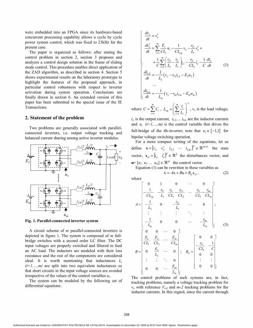
Fig. 1. Parallel-connected inverter system
A circuit scheme of m parallel-connected inverters is depicted in figure 1. The system is composed of m full-bridge switches with a second order LC filter. The DC input voltages are properly switched and filtered to feed an AC load. The inductors are modeled with their loss resistance and the rest of the components are considered ideal. It is worth mentioning that inductances Li (i=1,…,m) are split into two equivalent inductances so that short circuits in the input voltage sources are avoided irrespective of the values of the control variables ui.
The system can be modeled by the following set of differential equations:
( )
( )
1
1 1
1 1
2 1 1
22 2 2 2
2
1
1 1
1
...1
oo
mo i l
i o oi i eq
ml li l o
Li oi i
Lo l L
Lmo lm Lm m m
m
dvv
dtdv E r
u v vdt CL CL L
r r r dii i
C L L CL C dtdi
v r i E udt L
div r i E u
dt L
=
=
′= ′
′= − − + + − − − = − − − = − − −
∑
∑ (1)
where 1
m
ii
C C=
=∑ , 1
1
1m
eqi i
LL
−
=
= ∑ , vo is the load voltage,
io is the output current, iL2,… iLm are the inductor currents and iu (i=1,…,m) is the control variable that drives the full-bridge of the ith-inverter; note that 1,1iu ∈ − for bipolar voltage switching operation.
For a more compact writing of the equations, let us define [ ] 1
2+ℜ∈′= mT
LmLoo iivvx the state
vector, [ ] 2ℜ∈′= Tood iix the disturbances vector, and
u= [u1 u2 … um] mℜ∈ the control vector. Equation (1) can be rewritten in these variables as
x x u xd dA B B= + + , (2) where
1 1 2 1
1 1 2 1
2
2 2
1 2
1 2 1
12
2
0 1 0 01
1 ;0 0
1 0 0
0 0 00 0
1
0 0 ;0 0
00 0
0 0
l l l l lm
eq m
l
lm
m m
m
m l
d
m
m
r r r r rCL L CL CL CL CL
rA
L L
rL L
EE ECL CL CL r
CL CEB B
L
EL
− − − − = − − − −
− − = =
(3)
The control problems of such systems are, in fact, tracking problems, namely a voltage tracking problem for vo with reference Vref and m-2 tracking problems for the inductor currents. In this regard, since the current through
338
Authorized licensed use limited to: UNIVERSITAT POLITÈCNICA DE CATALUNYA. Downloaded on December 23, 2009 at 03:57 from IEEE Xplore. Restrictions apply.
L1 will be used as reference it must be computed from the state variables, i.e.
12
( ) ( ) ( )m
L o Li oi
i t i t i t Cv=
′= − +∑ (4)
3. A sliding mode solution
In accordance with the main guidelines of sliding mode control theory [13-14], the first step in the control design is to define as many switching surfaces as control variables so that the Ideal Sliding Dynamics coincides with the desired steady-state behaviour. Consider a master-slave strategy where the master role is assigned to the first inverter. Note that the output voltage vo is relative degree two with respect to all the inputs. Thus, the output voltage error is forced to perform a linear first order dynamics while all the slave inverter currents are compared to the master current iL1. Both AC output voltage regulation and balanced current sharing among the inverter modules can be achieved by the following set of switching surfaces
( ) ( ) ( )( )
( )
1 1 2
2 1 2
1
( ) ( ) ( ) ( )
( ) ( )
( ) ( )
ref o ref o
L L
m L Lm
dt k V t v t k V t v tdt
t i t i t
t i t i t
σ
σ
σ
= − + −
= −
= −
(5)
where ( ) sin( )refV t A tω= ⋅ is an external sinusoidal reference defined by the user, as well as the gains k1 and k2, and 1( )Li t is given by (4). The equations can be compacted as follows:
( ) ( ), v i r r Sd dt K K B B= + + +σ x x x x , (6)
where [ ] 2)()( ℜ∈′= Trefrefr tVtVx and , ,v i rK K B
and SdB are matrices whose elements can be easily deduced from (5).
A standard design procedure for control laws in MIMO systems is based on a decoupling approach. Namely, a change of variables in the switching surfaces or in the input variables is applied in order to reduce a MIMO control design problem to m-SISO problems. Since in power converters inputs typically model switching actions, and it is beneficial to preserve this relationship, the “sliding surfaces to control inputs” decoupling problem is solved by finding equivalent equations for the
sliding variety. A sufficient condition is that x
B∂∂σ
be an
invertible matrix of constant coefficients. As will be seen in next section, the use of a decoupling approach in control design allows direct application of the Zero Averaged Dynamics (ZAD) quasi-sliding control algorithm [8], which ensures the desirable fixed switching frequency operation of the system.
Lemma Since it will be used later, the transversally condition matrix and its inverse are calculated here,
i.
22 1 2 2
1 2
1 2
1 2
1
1
0x
0
m
m
m
m
k Ek E k ECL CL CLE EL LB
EEL L
− − −
−∂ = ∂ −
σ
ii. ( ) 2 1
1det 1
xm m
m
m k E EB
C L L∂ = − ∂
……
σ
iii.
( )
( )
1 1 1
2 1 1 1
21 2 2
2 2 2 2
2
11
x
1 mm m
m m m
CL L Lk E E E
m LCL Lk E E EB
m
m LCL Lk E E E
−
− −
− − ∂ = ∂ −
− −
σ
Proposition The MIMO design control problem results in m-SISO
design control problems provided that the following sliding surfaces are used:
( )
( )
1 1 22
2 1 22
1 22
1
1
m
m
m m
CkC mk
C mk
µ σ σ σ
µ σ σ σ
µ σ σ σ
= − + + +
= − − − + +
= − + + − −
…
…
… (7)
Proof µ-sliding surfaces are obtained from σ surfaces by the
change of variables 1
xB
−∂ Ω = ∆ ∂
σ, where ∆ is a
diagonal matrix with iii
i
Lm
E∆ = .
Proposition: Each of the new switching surfaces µi defined in (7)
depends on its own inverter inductor current, as well as on the load current and the output voltage and its derivative only, i.e:
( , , , )i Li o o of i i v vµ ′=
339
Authorized licensed use limited to: UNIVERSITAT POLITÈCNICA DE CATALUNYA. Downloaded on December 23, 2009 at 03:57 from IEEE Xplore. Restrictions apply.
Proof: It is straightforward using (7), (5) and (4).
Hence, the variables to be measured when implementing the control action driving the i-th inverter are Lii , oi , ov and ov′ only, which facilitates a modular conception of the power conversion system. The decoupling procedure gives
0 ( , )i ii i
i
d Ex t m u
dt Lµ µ= + (8)
Adding up to and subtracting the equivalent control, iequ from (8) results in
( ) ( )oi i i ii ieq i ieq i ieq
i i i
d E E E(x,t) m u m u u m u u
dt L L Lµ µ= + + − = −
(9)
and taking into account that 0 ( , ). iieq i
i
Lu x t
m Eµ= − , the
control law 1 0
( , )1 0
ii
i
if (x,t)u x t
if (x,t)µµ
+ <= − >
(10)
gives 0iµ = provided that 1 1 1...iequ i m− < < + = , (11)
which are necessary conditions for sliding motion when 1,1iu ∈ − .
Summarizing the controller design proceeds as follows: 1- to build the switching surfaces given by (5), 2- to obtain the decoupling surfaces from (7) and the corresponding dynamics as in (8) and, finally, 3- to apply the switching law defined in (10). 4. Fixed switching frequency operation
The robustness properties of sliding mode control
require the assumption of an infinite switching frequency operation which, in practice, leads to switching control actions occurring at a variable frequency rate. However, fixed switching frequency operation is often required in power electronics equipment since it not only facilitates filter elements design to avoid undesirable electromagnetic interferences, but also provides switching losses control to improve the system efficiency.
Additionally, a fixed-switching frequency operation allows the use of interleaving techniques for parallel-connected inverters aimed at reducing the output current ripple by properly shifting the inductor current of each inverter. In this sense, a modular inverter system interleaving operation preserving the robustness properties of the sliding mode control approach requires above all turning the original sliding mode based design into a fixed-frequency based one. In this paper, this is achieved through a Zero Averaged Dynamics quasi-sliding mode control algorithm (see [8] for further
details). Since the original MIMO control design problem for the sliding surfaces σ is turned into m-SISO control design problems for the sliding surfaces µ, the ZAD control algorithm can be directly applied, as in [8], to each surface µi.
5. Experimental Results
In order to validate the design, a set of experimental
results addressing both the steady-state and the transient behaviour of the modular inverter system have been obtained through a prototype of three parallel-connected inverters. The nominal operation of the modular system assumes that
· The three inverters are supplied by the same DC input voltage, which is set to 70V DC.
· The modular system must deliver an AC output voltage fixed by a reference signal of Vref(t)=55sin(100πt) to a resistive load of RL=5Ω, which corresponds to a total power of 300W.
As regards the modular inverter power stage, all the full-bridge switches were built by means of IRFP450 MOSFETs driven by IR2110 drivers, the switching frequency was fixed to 23kHz, the values of each inverter output filter capacitor were set to C1=C2=C3=20µF whereas the values of the corresponding output filter inductances were deliberately mismatched and set to L1=1.5mH, L2=1.22mH, L3=0.9mH, rL1=94mΩ, rL2=116mΩ, rL3=100mΩ in order to check inductor current equalization capability. It must be pointed out that this set of parameter values ensures the linear behaviour approximation of the switching surfaces required by proper ZAD algorithm operation [8].
Moreover, the control parameter values (i.e., the coefficient values of the sliding surfaces involved in (5)) were set to k1=1, k2=6e-5 taking into account the following considerations:
· Since k2/k1 > 0 is the time constant of the output voltage error sliding-mode transient response, this factor was adjusted in order to obtain a fast transient response as well as to verify the sliding mode conditions according to the criteria already reported in [9].
· The dynamic range limitation of the A/D Converters. Concerning several of the following experimental
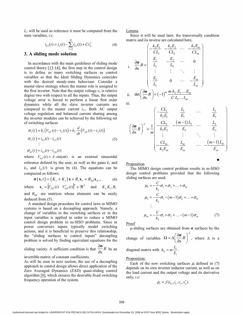
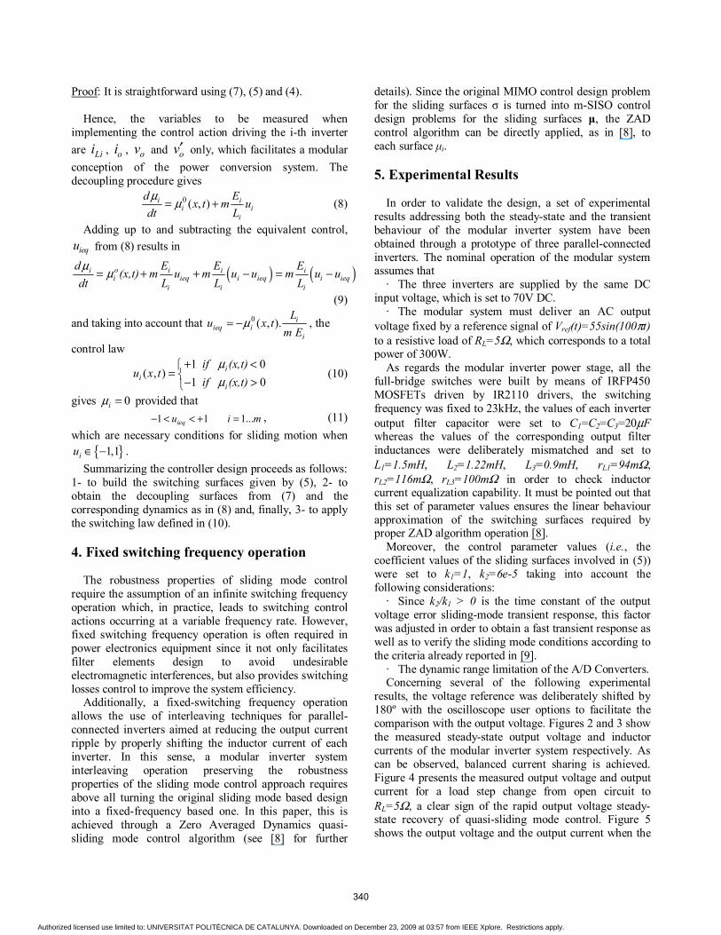
results, the voltage reference was deliberately shifted by 180º with the oscilloscope user options to facilitate the comparison with the output voltage. Figures 2 and 3 show the measured steady-state output voltage and inductor currents of the modular inverter system respectively. As can be observed, balanced current sharing is achieved. Figure 4 presents the measured output voltage and output current for a load step change from open circuit to RL=5Ω, a clear sign of the rapid output voltage steady-state recovery of quasi-sliding mode control. Figure 5 shows the output voltage and the output current when the
340
Authorized licensed use limited to: UNIVERSITAT POLITÈCNICA DE CATALUNYA. Downloaded on December 23, 2009 at 03:57 from IEEE Xplore. Restrictions apply.
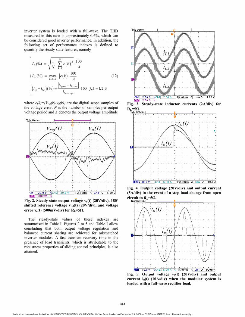
inverter system is loaded with a full-wave. The THD measured in this case is approximately 0.6%, which can be considered good inverter performance. In addition, the following set of performance indexes is defined to quantify the steady-state features, namely
( )
( )
( ) ( )
22
1
1..
1 100(%)
100(%) max
% 100 , 1,2,3
N
k
k N
Ljrms LkrmsLj Lk
Laverage
L e kN A
L e kA
i ii i j k
i
=
∞ =
= ⋅ = ⋅ − − = ⋅ =
∑
(12)
where e(k)=(Vref(k)-v0(k)) are the digital scope samples of the voltage error, N is the number of samples per output voltage period and A denotes the output voltage amplitude
vref(t) vo(t)
ve(t)
Fig. 2. Steady-state output voltage v0(t) (20V/div), 180º shifted reference voltage vref(t) (20V/div), and voltage error ve(t) (500mV/div) for RL=5Ω. The steady-state values of these indexes are summarised in Table I. Figures 2 to 5 and Table I allow concluding that both output voltage regulation and balanced current sharing are achieved for mismatched inverter modules. A fast transient recovery time in the presence of load transients, which is attributable to the robustness properties of sliding control principles, is also attained.
iL1
iL2
iL3
Fig. 3. Steady-state inductor currents (2A/div) for RL=5Ω.
vo(t)
io(t)
Fig. 4. Output voltage (20V/div) and output current (5A/div) in the event of a step load change from open circuit to RL=5Ω.
vo(t)
io(t)
Fig. 5. Output voltage v0(t) (20V/div) and output current i0(t) (10A/div) when the modular system is loaded with a full-wave rectifier load.
341
Authorized licensed use limited to: UNIVERSITAT POLITÈCNICA DE CATALUNYA. Downloaded on December 23, 2009 at 03:57 from IEEE Xplore. Restrictions apply.
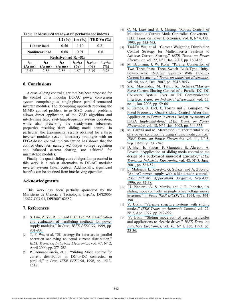
Table I: Measured steady-state performance indexes
L2 (%) L∞ (%) THD Vo (%) Linear load 0.56 1.10 0.21
Nonlinear load 0.68 0.91 0.6 Resistive load RL=5Ω
iL1 (Arms)
iL2 (Arms)
iL3 (Arms)
iL1-iL2 (%)
iL1-iL3 (%)
iL2-iL3 (%)
2.52 2.56 2.58 1.57 2.35 0.78
6. Conclusions
A quasi-sliding control algorithm has been proposed for
the control of a modular DC-AC power conversion system comprising m single-phase parallel-connected inverter modules. The decoupling approach reducing the MIMO control problem to m SISO control problems allows direct application of the ZAD algorithm and interleaving fixed switching-frequency system operation, while also preserving the steady-state robustness properties resulting from sliding mode control. In particular, the experimental results obtained for a three inverter modular system laboratory prototype with an FPGA-based control implementation has shown that the control objectives, namely AC output voltage regulation and balanced current sharing, are achieved for mismatched modules.
Finally, the quasi-sliding control algorithm presented in this work is a robust alternative to DC-AC modular inverter systems linear control. Additionally, significant benefits can be obtained from interleaving operation.
Acknowledgments
This work has been partially sponsored by the
Ministerio de Ciencia y Tecnología, España, DPI2006-15627-C03-01, DPI2007-62582. 7. References
[1] S. Luo, Z. Ye, R. Lin and F. C. Lee, “A classification
and evaluation of paralleling methods for power supply modules,” in Proc. IEEE PESC’99, 1999, pp. 901-908.
[2] T. F. Wu, et al. “3C strategy for inverters in parallel operation achieving an equal current distribution,” IEEE Trans. on Industrial Electronics, vol. 47, Nº 2, April 2000, pp. 273-281.
[3] P. Donoso-Garcia, et al. “Sliding Mode control for current distribution in DC-to-DC connected in parallel,” in Proc. IEEE PESC’96, 1996, pp. 1513-1518.
[4] C. M. Liaw and S. J. Chiang, “Robust Control of Multimodule Current-Mode Controlled Converters,” IEEE Trans. on Power Electronics, Vol. 8, Nº 4, Oct. 1993, pp. 455-465.
[5] Tsai-Fu Wu, et al. “Current Weighting Distribution Control Strategy for Multi-Inverter Systems to Achieve Current Sharing,” IEEE Trans. on Power Electronics, vol. 22, Nº 1, Jan. 2007, pp. 160-168.
[6] M. Baumann, J. W. Kolar, "Parallel Connection of Two Three-Phase Three-Switch Buck-Type Unity-Power-Factor Rectifier Systems With DC-Link Current Balancing," Trans. on Industrial Electronics, vol. 54, no. 6, Dec. 2007, pp. 3042-3053.
[7] S.K. Mazumder, M. Tahir, K. Acharya.“Master–Slave Current-Sharing Control of a Parallel DC–DC Converter System Over an RF Communication Interface. Trans. on Industrial Electronics, vol. 55, no. 1, Jan. 2008, pp. 59-66.
[8] R. Ramos, D. Biel, E. Fossas and F. Guinjoan, “A Fixed-Frequency Quasi-Sliding Control Algorithm: Application to Power Inverters Design by means of FPGA Implementation,” IEEE Trans. on Power Electronics, vol. 18, Nº 1, Jan. 2003, pp. 344-355.
[9] M. Carpita and M. Marchesoni, “Experimental study of a power conditioning using sliding mode control,” IEEE Trans. on Power Electronics, vol. 11, Nº 5, Sep. 1996, pp. 731-742.
[10] D. Biel, E. Fossas, F. Guinjoan, E, Alarcon, A. Poveda. “Application of sliding-mode control to the design of a buck-based sinusoidal generator,” IEEE Trans. on Industrial Electronics, vol. 48, Nº 3, June. 2001, pp. 563-571.
[11] L. Malesani, L. Rossetto, G. Spiazzi and A. Zuccato, “An AC power supply with sliding-mode control,” IEEE Industry Applications Magazine, Sep.-Oct. 1996, pp. 32-38.
[12] H. Pinheiro, A. S. Martins and J. R. Pinheiro, “A sliding mode controller in single phase voltage source inverters,” in Proc. IEEE IECON’94, 1994, pp. 394-398.
[13] V. Utkin, “Variable structure systems with sliding modes,” IEEE Trans. on Automatic Control, vol. 22, Nº 2, Apr. 1977, pp. 212-222.
[14] V. Utkin, “Sliding mode control design principles and applications to electric drives,” IEEE Trans. on Industrial Electronics, vol. 40, Nº 1, Feb. 1993, pp. 23-36.
342
Authorized licensed use limited to: UNIVERSITAT POLITÈCNICA DE CATALUNYA. Downloaded on December 23, 2009 at 03:57 from IEEE Xplore. Restrictions apply.
Copyright © 2022 FDOKUMEN