On-demand generation of monodisperse femtolitre droplets by shape-induced shear
7
On-demand generation of monodisperse femtolitre droplets by shape-induced shear† Seung-Yong Jung, a Scott T. Retterer ab and C. Patrick Collier * a Received 16th June 2010, Accepted 28th July 2010 DOI: 10.1039/c0lc00120a We describe a method for creating discrete femtolitre-scale water-in-oil droplets on demand, based solely on a geometrically induced reduction in oil/water interfacial area at microfabricated junction orifices. This on-demand generation method is driven by self-shear of droplets due to interfacial tension induced forces resulting from a localized transition in microchannel height. The magnitudes of shear stresses involved appear to be significantly less than the shearing instabilities used to split off daughter droplets from aqueous mother plugs at microfabricated junctions in continuous water-in-oil segmented flows, which implies that this method may be better suited for studying biochemical reactions and reaction kinetics in droplets of decreased volume without loss of chemical reactivity due to redistribution of surfactant density used to passivate the oil/water interface. Predictable droplet generation rates under constant pressure conditions or the gated formation of one, two or more droplets at a time with fixed pressure pulses have been demonstrated in a similar manner to active on-demand droplet generation strategies, but with a simpler system not needing actuation and sensing equipment beyond a pressure regulator. Introduction Droplet-based microfluidic platforms offer many opportunities to confine chemical and biochemical reactants in discrete ultra- small reaction volumes, and investigate the effects of increased confinement on reaction kinetics. 1,2 Most droplet-based systems rely on generation of continuous streams of droplets in multi- phase segmented flows, either via a ‘‘squeezing’’ mechanism involving pressure fluctuations related to periodic blocking of oil flow in a channel by aqueous plugs, or by ‘‘dripping’’ or ‘‘jetting’’ mechanisms involving shearing of the aqueous phase by the oil phase. 3,4 Droplets are generated in such flows at high frequencies and transported downstream at high flow rates, which compli- cates efforts to initiate chemical reactions with a well-defined time zero, analyze reaction kinetics in real time, and further manipulate droplets to carry out sequential multistep reactions. In addition, generation of the smallest droplet sizes (1–10 mm in diameter) due to droplet splitting generally requires strong shear stresses, which can adversely affect the distribution of surfactant stabilizing the oil–water interface and the passivation of the interface against nonspecific adsorption of biomolecules such as enzymes. 5 On-demand generation of droplets allows more precise temporal control of reactions inside droplets since each droplet can be individually triggered, tracked and manipulated. Methods to control droplet splitting on demand involve thinning or breaking the aqueous thread connecting a growing droplet to the water pore to which it is attached, due to local extensional and shear stresses at the orifice. 6,7 The resulting size of the droplet, or whether or not multiple droplets or even aqueous jets are injected into the oil phase, will depend on competition between the rates of thinning of the aqueous thread versus inflation of the droplet by fluid flow through the orifice. 8 For water-in-oil droplets created rapidly under steady-state conditions with continuous segmented flows, shear is provided by the cross-flow of the oil phase. To form individual droplets on demand without cross-flow, some other mechanism is necessary to create sufficient shear. Recent examples of on-demand droplet generation methods in the absence of steady-state cross-flows include the use of programmable microinjectors, 9 syringe pumps, 10,11 piezoelectric actuators, 12 high-voltage pulses, 13,14 electrowetting on dielec- trics, 15 and use of dielectrophoretic pressure. 16 These methods rely on actively controlled mechanical displacements of the water–oil interface sufficient to split off aqueous droplets one at a time at junctions of aqueous and oil channels. On the other hand, continuous multiphase flows in microchannels generally rely on passive means for forming water-in-oil droplets, based on flow instabilities induced by interfacial forces. This paper describes a method for creating individual femto- litre scale aqueous droplets on demand at a junction between an aqueous and oil channel in the absence of cross-flow, based on an abrupt increase in the oil channel height relative to that of the aqueous channel. This increase in channel height permits a droplet to attain its lowest energy spherical shape, which creates an interfacial tension induced force on the droplet suffi- cient to detach it from the orifice. Similar mechanisms have been described in reports of surface tension guided droplet storage in nanolitre wells, 17,18 droplet formation in microchannel a Center for Nanophase Materials Sciences, Oak Ridge National Laboratory, P.O. Box 2008, MS-6493, Oak Ridge, Tennessee, 37831, USA. E-mail: [email protected] b Biological and Nanoscale Systems Group, Biosciences Division, Oak Ridge National Laboratory, Oak Ridge, TN, 37831-6445, USA † Electronic supplementary information (ESI) available: Sequences of bright field images captured with CCD camera and high-speed CMOS camera of droplet formation dynamics, data files of droplet formation intervals and droplet diameter distributions, device fabrication using hPDMS. See DOI: 10.1039/c0lc00120a 2688 | Lab Chip, 2010, 10, 2688–2694 This journal is ª The Royal Society of Chemistry 2010 PAPER www.rsc.org/loc | Lab on a Chip Downloaded by UNIVERSITY OF TENNESSEE AT KNOXVILLE on 06 October 2010 Published on 19 August 2010 on http://pubs.rsc.org | doi:10.1039/C0LC00120A View Online
-
Upload
independent -
Category
Documents
-
view
0 -
download
0
Transcript of On-demand generation of monodisperse femtolitre droplets by shape-induced shear

PAPER www.rsc.org/loc | Lab on a Chip
Dow
nloa
ded
by U
NIV
ER
SIT
Y O
F T
EN
NE
SSE
E A
T K
NO
XV
ILL
E o
n 06
Oct
ober
201
0Pu
blis
hed
on 1
9 A
ugus
t 201
0 on
http
://pu
bs.r
sc.o
rg |
doi:1
0.10
39/C
0LC
0012
0AView Online
On-demand generation of monodisperse femtolitre droplets by shape-inducedshear†
Seung-Yong Jung,a Scott T. Rettererab and C. Patrick Collier*a
Received 16th June 2010, Accepted 28th July 2010
DOI: 10.1039/c0lc00120a
We describe a method for creating discrete femtolitre-scale water-in-oil droplets on demand, based
solely on a geometrically induced reduction in oil/water interfacial area at microfabricated junction
orifices. This on-demand generation method is driven by self-shear of droplets due to interfacial tension
induced forces resulting from a localized transition in microchannel height. The magnitudes of shear
stresses involved appear to be significantly less than the shearing instabilities used to split off daughter
droplets from aqueous mother plugs at microfabricated junctions in continuous water-in-oil segmented
flows, which implies that this method may be better suited for studying biochemical reactions and
reaction kinetics in droplets of decreased volume without loss of chemical reactivity due to
redistribution of surfactant density used to passivate the oil/water interface. Predictable droplet
generation rates under constant pressure conditions or the gated formation of one, two or more
droplets at a time with fixed pressure pulses have been demonstrated in a similar manner to active
on-demand droplet generation strategies, but with a simpler system not needing actuation and sensing
equipment beyond a pressure regulator.
Introduction
Droplet-based microfluidic platforms offer many opportunities
to confine chemical and biochemical reactants in discrete ultra-
small reaction volumes, and investigate the effects of increased
confinement on reaction kinetics.1,2 Most droplet-based systems
rely on generation of continuous streams of droplets in multi-
phase segmented flows, either via a ‘‘squeezing’’ mechanism
involving pressure fluctuations related to periodic blocking of oil
flow in a channel by aqueous plugs, or by ‘‘dripping’’ or ‘‘jetting’’
mechanisms involving shearing of the aqueous phase by the oil
phase.3,4 Droplets are generated in such flows at high frequencies
and transported downstream at high flow rates, which compli-
cates efforts to initiate chemical reactions with a well-defined
time zero, analyze reaction kinetics in real time, and further
manipulate droplets to carry out sequential multistep reactions.
In addition, generation of the smallest droplet sizes (1–10 mm in
diameter) due to droplet splitting generally requires strong shear
stresses, which can adversely affect the distribution of surfactant
stabilizing the oil–water interface and the passivation of the
interface against nonspecific adsorption of biomolecules such as
enzymes.5 On-demand generation of droplets allows more precise
temporal control of reactions inside droplets since each droplet
can be individually triggered, tracked and manipulated.
aCenter for Nanophase Materials Sciences, Oak Ridge NationalLaboratory, P.O. Box 2008, MS-6493, Oak Ridge, Tennessee, 37831,USA. E-mail: [email protected] and Nanoscale Systems Group, Biosciences Division, Oak RidgeNational Laboratory, Oak Ridge, TN, 37831-6445, USA
† Electronic supplementary information (ESI) available: Sequences ofbright field images captured with CCD camera and high-speed CMOScamera of droplet formation dynamics, data files of droplet formationintervals and droplet diameter distributions, device fabrication usinghPDMS. See DOI: 10.1039/c0lc00120a
2688 | Lab Chip, 2010, 10, 2688–2694
Methods to control droplet splitting on demand involve
thinning or breaking the aqueous thread connecting a growing
droplet to the water pore to which it is attached, due to local
extensional and shear stresses at the orifice.6,7 The resulting size
of the droplet, or whether or not multiple droplets or even
aqueous jets are injected into the oil phase, will depend on
competition between the rates of thinning of the aqueous thread
versus inflation of the droplet by fluid flow through the orifice.8
For water-in-oil droplets created rapidly under steady-state
conditions with continuous segmented flows, shear is provided
by the cross-flow of the oil phase.
To form individual droplets on demand without cross-flow,
some other mechanism is necessary to create sufficient shear.
Recent examples of on-demand droplet generation methods in
the absence of steady-state cross-flows include the use of
programmable microinjectors,9 syringe pumps,10,11 piezoelectric
actuators,12 high-voltage pulses,13,14 electrowetting on dielec-
trics,15 and use of dielectrophoretic pressure.16 These methods
rely on actively controlled mechanical displacements of the
water–oil interface sufficient to split off aqueous droplets one at
a time at junctions of aqueous and oil channels. On the other
hand, continuous multiphase flows in microchannels generally
rely on passive means for forming water-in-oil droplets, based on
flow instabilities induced by interfacial forces.
This paper describes a method for creating individual femto-
litre scale aqueous droplets on demand at a junction between an
aqueous and oil channel in the absence of cross-flow, based on an
abrupt increase in the oil channel height relative to that of the
aqueous channel. This increase in channel height permits
a droplet to attain its lowest energy spherical shape, which
creates an interfacial tension induced force on the droplet suffi-
cient to detach it from the orifice. Similar mechanisms have been
described in reports of surface tension guided droplet storage in
nanolitre wells,17,18 droplet formation in microchannel
This journal is ª The Royal Society of Chemistry 2010
Dow
nloa
ded
by U
NIV
ER
SIT
Y O
F T
EN
NE
SSE
E A
T K
NO
XV
ILL
E o
n 06
Oct
ober
201
0Pu
blis
hed
on 1
9 A
ugus
t 201
0 on
http
://pu
bs.r
sc.o
rg |
doi:1
0.10
39/C
0LC
0012
0AView Online
emulsification membranes19 and arrays,20 and droplet formation
by Rayleigh-Plateau instabilities generated across a micro-
fabricated step.21 Monodisperse droplets were created at regular
intervals, up to several seconds between successive droplets,
simply by using constant backing pressure slightly higher than
the capillary pressure. This slow and predictable droplet
formation rate allows each individual droplet to be tracked and
manipulated separately and continuously in the main channel in
real time, in a similar manner to active on-demand droplet
generation strategies described above, but with a simpler system
not needing bulky actuation and sensing equipment. The only
control element that is needed outside the microfluidic chip is
a pressure regulator. In addition, pulsed output of the pressure
regulator allows droplet formation to be gated, due to the
predictable droplet generation rates at the junction. One, two, or
more droplets per pulse could be produced at a time, depending
on the width and magnitude of the pressure pulse.
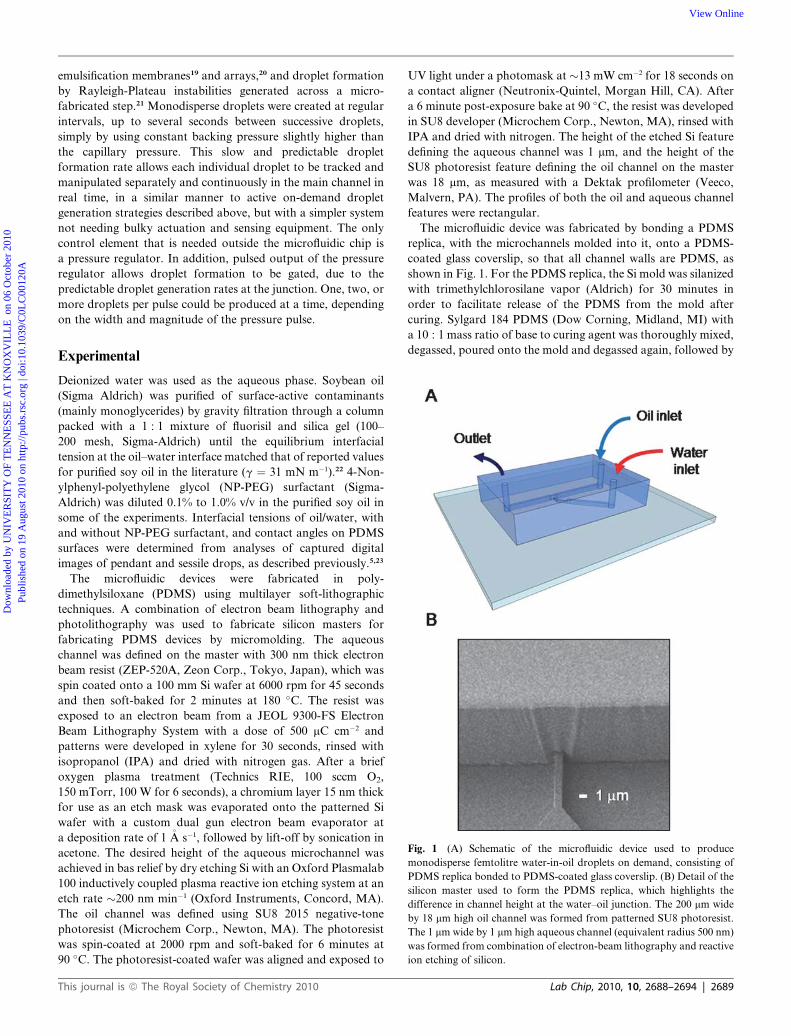
Fig. 1 (A) Schematic of the microfluidic device used to produce
monodisperse femtolitre water-in-oil droplets on demand, consisting of
PDMS replica bonded to PDMS-coated glass coverslip. (B) Detail of the
silicon master used to form the PDMS replica, which highlights the
difference in channel height at the water–oil junction. The 200 mm wide
by 18 mm high oil channel was formed from patterned SU8 photoresist.
The 1 mm wide by 1 mm high aqueous channel (equivalent radius 500 nm)
was formed from combination of electron-beam lithography and reactive
ion etching of silicon.
Experimental
Deionized water was used as the aqueous phase. Soybean oil
(Sigma Aldrich) was purified of surface-active contaminants
(mainly monoglycerides) by gravity filtration through a column
packed with a 1 : 1 mixture of fluorisil and silica gel (100–
200 mesh, Sigma-Aldrich) until the equilibrium interfacial
tension at the oil–water interface matched that of reported values
for purified soy oil in the literature (g ¼ 31 mN m�1).22 4-Non-
ylphenyl-polyethylene glycol (NP-PEG) surfactant (Sigma-
Aldrich) was diluted 0.1% to 1.0% v/v in the purified soy oil in
some of the experiments. Interfacial tensions of oil/water, with
and without NP-PEG surfactant, and contact angles on PDMS
surfaces were determined from analyses of captured digital
images of pendant and sessile drops, as described previously.5,23
The microfluidic devices were fabricated in poly-
dimethylsiloxane (PDMS) using multilayer soft-lithographic
techniques. A combination of electron beam lithography and
photolithography was used to fabricate silicon masters for
fabricating PDMS devices by micromolding. The aqueous
channel was defined on the master with 300 nm thick electron
beam resist (ZEP-520A, Zeon Corp., Tokyo, Japan), which was
spin coated onto a 100 mm Si wafer at 6000 rpm for 45 seconds
and then soft-baked for 2 minutes at 180 �C. The resist was
exposed to an electron beam from a JEOL 9300-FS Electron
Beam Lithography System with a dose of 500 mC cm�2 and
patterns were developed in xylene for 30 seconds, rinsed with
isopropanol (IPA) and dried with nitrogen gas. After a brief
oxygen plasma treatment (Technics RIE, 100 sccm O2,
150 mTorr, 100 W for 6 seconds), a chromium layer 15 nm thick
for use as an etch mask was evaporated onto the patterned Si
wafer with a custom dual gun electron beam evaporator at
a deposition rate of 1 �A s�1, followed by lift-off by sonication in
acetone. The desired height of the aqueous microchannel was
achieved in bas relief by dry etching Si with an Oxford Plasmalab
100 inductively coupled plasma reactive ion etching system at an
etch rate �200 nm min�1 (Oxford Instruments, Concord, MA).
The oil channel was defined using SU8 2015 negative-tone
photoresist (Microchem Corp., Newton, MA). The photoresist
was spin-coated at 2000 rpm and soft-baked for 6 minutes at
90 �C. The photoresist-coated wafer was aligned and exposed to
This journal is ª The Royal Society of Chemistry 2010
UV light under a photomask at �13 mW cm�2 for 18 seconds on
a contact aligner (Neutronix-Quintel, Morgan Hill, CA). After
a 6 minute post-exposure bake at 90 �C, the resist was developed
in SU8 developer (Microchem Corp., Newton, MA), rinsed with
IPA and dried with nitrogen. The height of the etched Si feature
defining the aqueous channel was 1 mm, and the height of the
SU8 photoresist feature defining the oil channel on the master
was 18 mm, as measured with a Dektak profilometer (Veeco,
Malvern, PA). The profiles of both the oil and aqueous channel
features were rectangular.
The microfluidic device was fabricated by bonding a PDMS
replica, with the microchannels molded into it, onto a PDMS-
coated glass coverslip, so that all channel walls are PDMS, as
shown in Fig. 1. For the PDMS replica, the Si mold was silanized
with trimethylchlorosilane vapor (Aldrich) for 30 minutes in
order to facilitate release of the PDMS from the mold after
curing. Sylgard 184 PDMS (Dow Corning, Midland, MI) with
a 10 : 1 mass ratio of base to curing agent was thoroughly mixed,
degassed, poured onto the mold and degassed again, followed by
Lab Chip, 2010, 10, 2688–2694 | 2689

Dow
nloa
ded
by U
NIV
ER
SIT
Y O
F T
EN
NE
SSE
E A
T K
NO
XV
ILL
E o
n 06
Oct
ober
201
0Pu
blis
hed
on 1
9 A
ugus
t 201
0 on
http
://pu
bs.r
sc.o
rg |
doi:1
0.10
39/C
0LC
0012
0AView Online
curing for 30 minutes at 120 �C. The cured PDMS replica was
peeled off from mold and holes were punched with a 0.75 mm
hole-puncher (Harris Uni-Core, Ted Pella, Inc. Redding, CA).
The PDMS replica was bonded onto a #1 glass coverslip (Erie
Scientific Co., Portsmouth, NH) that had a 10 mm thick layer of
PDMS spin coated onto it (6500 rpm), followed by curing for 30
minutes at 120 �C. Bonding between the top PDMS replica and
the bottom PDMS-coated glass coverslip was activated by
plasma treatment of both bonding surfaces in an inductively
coupled plasma cleaner at 10.5 W for 20 seconds (Harrick,
Ithaca, NY). In order to render all the channel surfaces of the
completed device sufficiently hydrophobic, the bonded chips
were heated at 120 �C for an additional 48 hours to ensure
hydrophobic recovery of the PDMS.
4 mL glass vials with PTFE/silicone septum lids (C4015-17W,
National Scientific, Rockwood, TN) were used as sample reser-
voirs for the aqueous and oil phases, and were connected to high
precision closed-loop voltage–pressure transducers (Marsh
Bellofram, Newell, WV) by 24 gauge PTFE tubing (Small Parts,
Miramar, FL). The reservoirs were connected to the inlets of the
PDMS device by 23 gauge stainless steel tubing (Technical
Innovations, Brazoria, TX). Male-to-male luer lock adapters
(Qosina, Edgewood, NY) holding two 23 gauge needles, one
penetrating the septum of the vial cap, and the other connecting
to the 24 gauge PTFE tubing, were used for access into and out of
the sample vials. The pressure regulators were controlled by
a custom Matlab script (Mathworks, Natick, MA) through an
analog output board (16 bit resolution, 0–10 V range, USB3103,
Measurement Computing, Norton, MA), and were calibrated
using a Dwyer Series 475 Mark III digital manometer (Michigan
City, IN). Bright field images were acquired with an inverted
optical microscope (Eclipse TE 300, Nikon Instruments,
Melville, NY), using either a CCD camera (CoolSNAP-HQ,
Roper Scientific, Tucson, AZ) controlled with Metamorph
software (Universal Imaging Corp., Downing Town, PA), or
a high-speed CMOS camera (EPIX SV643, Buffalo Grove, IL).
Images were analyzed with ImageJ software (National Institutes
of Health).
Fig. 2 (A) Series of bright field images spaced at 82 ms intervals of the
formation and detachment of an individual 5.7 mm diameter droplet from
an aqueous channel (1 � 1 mm) into the oil phase, at a constant backing
pressure of 130.3 kPa. (B) Cross-sectional schematic of steps involved
during droplet formation corresponding to bright field images in (A).
Results and discussion
In order to form only one droplet from an orifice at a time,
actively controlled methods have been used to transiently bring
the internal pressure at the curved interface above the capillary
hold-off value without allowing subsequent drops to form until
needed.9–16 Regulation of just the backing hydrostatic pressure at
the orifice with enough precision for this degree of control has
not been demonstrated to date. This degree of control may be
achieved, however, by increasing the resistance to fluid flow in
the channel while providing a mechanism for shearing the
nascent droplet at the orifice.
At these scales, consideration of capillary effects due to the
surface energetics of the water and oil fluids with the hydro-
phobic PDMS channel walls become important. To form discrete
aqueous droplets on demand in an oil phase, the channel walls
must be kept hydrophobic; otherwise, the aqueous phase would
wet the walls of the oil channel without forming discrete droplets.
On the other hand, for hydrophobic channel walls wetted with
oil, a resistive capillary pressure must be overcome by the applied
2690 | Lab Chip, 2010, 10, 2688–2694
backing pressure in order to fill the aqueous channel with water.
For a rectangular channel, this pressure will depend on the
interfacial tension between the two immiscible phases
(g¼ 31 mN m�1 for purified soybean oil and water), the cosine of
the contact angle of the wetting fluid with the channel wall
(qoil with purified soybean oil was measured to be �20 to 30� on
hydrophobic PDMS), and the two radii of curvature associated
with one-half of the width, a¼ 1.0 mm, and height, b¼ 1.0 mm, of
the channel,24
PC ¼ 2g cos qoil
�1
aþ 1
b
�z110� 117 kPa (1)
Experimental values for the backing pressure required to fill
the 1 � 1 mm aqueous channel, PC0, were slightly higher than this
estimate, about 124–131 kPa, due to a combination of factors
increasing local flow resistance in the channel, including surface
roughness of the channel walls, and minor defects/obstructions in
the channel and junction orifice in the PDMS replica formed
during molding. These non-uniform variations in flow resistance
prevented control of fluid flow with the precision and accuracy
required for forming droplets on demand for channel lengths
greater than 7 mm. This also prevented precise positioning the oil/
water interface as a function of backing pressure exactly at the
opening into the oil channel without uncontrolled injection of
multiple droplets into the oil phase. Instead, the closest stable
position of the oil/water interface to the opening tended to be
slightly behind it, inside the aqueous channel. For this reason, the
backing pressure PC0 was adjusted such that the oil/water inter-
face was positioned as close as possible to, but not at the channel
opening. This position was stable indefinitely and was a repro-
ducible function of backing pressure. For the images in
Fig. 2A, the backing pressure necessary to fill the aqueous
channel and maintain the oil/water interface at this position was
This journal is ª The Royal Society of Chemistry 2010

Fig. 3 (A) Plot of droplet formation intervals from a 1 � 1 mm orifice as
functions of the pressure difference DP across the water–oil interface. The
inset shows that at and above DP ¼ 1.0 kPa, the droplet formation
interval is affected by previously formed droplets. (B) Droplet diameter
size distribution histogram corresponding to steady-state droplet
formation over the range of DP values in (A).
Dow
nloa
ded
by U
NIV
ER
SIT
Y O
F T
EN
NE
SSE
E A
T K
NO
XV
ILL
E o
n 06
Oct
ober
201
0Pu
blis
hed
on 1
9 A
ugus
t 201
0 on
http
://pu
bs.r
sc.o
rg |
doi:1
0.10
39/C
0LC
0012
0AView Online
PC0 ¼ 130.1 kPa. Because the flow resistances depended sensi-
tively on local variations in width in the aqueous injection
channel, the precise location of the pinned interface varied from
one device to the next. From numerous bright field images,
including those shown in Fig. 2A, we determined the mean and
standard deviation of the stable position of the interface to be
1.3 mm � 0.6 mm from the orifice.
Fig. 2A shows a series of bright field images, captured with
a CCD camera every 82 ms (corresponding to the maximum frame
transfer rate for the imaged pixel area), of an individual 5.7 mm
diameter droplet forming and detaching from the orifice at the
junction of a 1 mm wide� 1 mm high� 7 mm long aqueous channel
with a 200 mm wide � 18 mm high main oil channel. The corre-
sponding movie can be found in the ESI†. This sequence was not
triggered, but instead represents a series of successive ‘‘snapshots’’
taken under steady-state conditions, at a constant applied backing
pressure of 130.3 kPa. Fig. 2B shows a schematic of the proposed
droplet formation mechanism from a side-view perspective.
In the first panel of Fig. 2A and B, the curved oil/water
interface has started to protrude from the junction orifice with
a hemispherical shape, which indicates the internal pressure
acting on the water/oil interface is at or very close to the capillary
hold-off value corresponding to spontaneous growth of the
aqueous phase into the oil channel.16 By the next frame (within
82 ms), a fully grown droplet has formed at the interface, con-
nected to the water channel by an aqueous neck. Bright field
images captured with a fast CMOS camera (frame rate 841 ms)
indicate that the droplet formation process, beginning with the
oil/water interface at the capillary hold-off value, is complete
within 2.5 ms (see ESI†).
The distance from the floor of the device to the centerline
of the aqueous channel (500 nm) is significantly less than that
from the ceiling of the device to this centerline (17.5 mm). We
believe the key enabling process for droplet detachment on
demand for our device is the abrupt change in channel height
across the junction orifice, from the 1 mm height of the aqueous
channel to the 18 mm height of the oil channel. This increase in
height allows the rapidly growing droplet room to expand both
vertically and horizontally away from the orifice in order to
minimize the surface area of the droplet by approximating
a spherical shape above the centerline of the orifice. However, at
the hydrophobic floor and wall of the channel near the opening,
the droplet shape is distorted from spherical due to steric
hindrance.
This can be seen in the second panel of Fig. 2A and B, which
show an inflated droplet, the shape of which is clearly distorted
from spherical, near the channel wall. The local Laplace pressure
at the nose of the droplet is less than that at the neck due to
differences in the radii of curvature. The resulting pressure
gradient results in local extensional and shear stresses at the oil–
water interface that drives the growth of an oil film and thinning
of the aqueous neck at the orifice.
This process results in the droplet splitting off from the orifice
and recovering its lowest energy spherical shape.6,7 The newly
freed droplet then drifts away from the orifice in the remaining
panels, presumably due to slow fluid flow in the main oil channel
from a slight hydrostatic pressure imbalance between the inlet
and outlet of the oil channel. If needed, this slow drift in the oil
channel could be controlled with pressure regulators.
This journal is ª The Royal Society of Chemistry 2010
Fig. 3A is a plot of steady-state droplet formation intervals for
this channel geometry as a function of the pressure drop across
the water–oil interface in the aqueous channel, taken from over
50 bright field images. These data are included in the ESI†. We
assigned the pressure drop across the oil/water interface to be
equal to the difference between the applied backing pressure and
an effective capillary pressure of the channel, DP ¼ Pa � PC0. As
described above, PC0 corresponds to the minimum backing
pressure required to pin the interface at its closest stable position
behind the channel opening without flooding the oil channel;
DP ¼ 0 refers to an applied backing pressure equaling this
effective capillary pressure. The difference between neighboring
DP values in the plot, 0.2 kPa, corresponds to the resolution of
the voltage–pressure transducers used to regulate the backing
pressure, which was 0.1% of full scale (200 kPa).
Analyses of time dependent sequences of bright field images
taken at each value of DP were used to generate the mean and
standard deviation for each data point in Fig. 3A. Included in the
Lab Chip, 2010, 10, 2688–2694 | 2691

Fig. 4 Still images of droplet formation during pulsed operation from
four different movie sequences: (A) 10 ms pulse, Pa ¼ 134.5 kPa, (B) 10
ms pulse, Pa ¼ 138.6 kPa, (C) 15 ms pulse, Pa ¼ 134.5 kPa and (D) 20 ms
pulse, Pa ¼ 134.5 kPa.
Dow
nloa
ded
by U
NIV
ER
SIT
Y O
F T
EN
NE
SSE
E A
T K
NO
XV
ILL
E o
n 06
Oct
ober
201
0Pu
blis
hed
on 1
9 A
ugus
t 201
0 on
http
://pu
bs.r
sc.o
rg |
doi:1
0.10
39/C
0LC
0012
0AView Online
plot is a linear fit (R2 ¼ 0.98) to the data except for the last data
point at DP ¼ 1.0 kPa, which did not follow the linear trend due
to blocking of the aqueous channel opening by previously
formed droplets, as shown by the image in the inset.
Bright field image sequences for the range of DP values used in
Fig. 3A show that for most of the time between successive droplet
generation events (1 to 3.5 seconds, depending on DP), the water/
oil interface in the aqueous channel was pinned at its stable initial
position within the aqueous channel. The growth and detach-
ment of a droplet were rare, transient events within each droplet
generation cycle, occurring rapidly (within 2.5 ms) once the
interface moved to the channel opening and started to protrude
into the oil phase. As each droplet split off from the orifice, the
water/oil interface of the remaining water column recoiled back
to its initial stable position within the aqueous channel, due to
interfacial tension, to begin a new cycle. A detailed description of
the complex time-dependent behavior is beyond the scope of this
paper, but the hydrodynamics should be similar to that of
a macroscale dripping faucet, albeit with surface interactions
such as interfacial tension and contact angles dominating volume
effects such as gravity or inertial forces.
Fig. 3B is a plot of the droplet diameter size distribution
observed from bright field image sequences corresponding to 0.2
to 1.0 kPa, the range of DP values shown in Fig. 3A. The mean
and standard deviation from this distribution was 5.7 � 0.2 mm,
resulting in a coefficient of variation (COV ¼ std/m � 100%) of
3.5%. This diameter corresponds to a volume of 97 femtolitres
for a spherical droplet. The fact that the droplet size distribution
was relatively independent of the backing pressures used and
frequencies of droplet formation are consistent with the fact that
the ultimate droplet diameter is controlled more by interfacial
tension than flow rate at this length scale.
The slow, predictable droplet generation intervals shown in
Fig. 3A represent a different droplet formation methodology
than steady-state approaches to produce droplets at high
formation frequencies (up to kHz) based on continuous
segmented flows, and allows interrogation, tracking and
manipulation of individual droplets in the same way as active-
control schemes for on-demand generation. This slow, predict-
able steady-state rate also enables droplet formation to be gated,
by application of pressure pulses instead of a constant applied
pressure.
Fig. 4 shows still images of droplet formation occurring after
the application of a short pressure pulse (10–20 ms pulse dura-
tion). The number of droplets per pulse could be controlled either
with the magnitude (Fig. 4A and B) or the duration (Fig. 4C and
D) of the pressure pulse. Comparison of Fig. 4A and B shows
that an increase in DP of just 4.1 kPa, for the same pulse duration
(10 ms), results in a transition from one droplet per pulse for
Fig. 4A to numerous droplets per pulse for Fig. 4B. For Fig. 4B,
there were actually two sets of four-droplet injections per pulse,
due to transient pressure oscillations from the Marsh-Bellofram
voltage-to-pressure transducer.
Varying the duration of the pressure pulse was an easier way to
control the number of droplets per pulse in a digital manner than
varying the magnitude of the pressure pulse. Comparison of
Fig. 4A, C and D shows that by increasing the duration of the
pulse from 10 ms to 15 ms to 20 ms, all at Pa ¼ 134.5 kPa, one,
two or three droplets could be produced on demand
2692 | Lab Chip, 2010, 10, 2688–2694
reproducibly. Oscillations in the positions of the oil/water
interface in the channel occurred after each pulse due to the
pressure transducer, but the oscillations did not extend all the
way to the orifice of the channel as they did for Fig. 4B because
the pressure was lower.
Our hypothesis that the droplet formation mechanism is based
on the discontinuity in channel height at the oil/water channel
junction was tested by increasing the height of the aqueous
channel from 1.0 to 3.3 mm, corresponding to an increase in the
channel aspect ratio from 1 : 1 to 1 : 3. We found that the
structural strength of the commercial PDMS used (Sylgard 184)
for the 1 : 1 aspect ratio aqueous channel was not sufficient for
the 1 : 3 aspect ratio channels, which were prone to collapse
during pattern transfer. Therefore, a harder PDMS formulation
(hPDMS) with increased modulus was used for these channels.25
Our prediction was that a lower backing pressure would be
needed for filling the 1 : 3 aspect ratio channels, corresponding to
a lower expected capillary pressure in eqn (1). Our prediction was
verified; the backing pressure needed for forming droplets from
the 1 : 3 aspect ratio channels was 56.6 kPa, compared to
130.3 kPa for the 1 : 1 aspect ratio channels. In addition, we
predicted that the final droplet diameter would be larger for the
1 : 3 aspect ratio channel compared to the 1 : 1 aspect ratio
channel, since the distance from the axial centerline of the
aqueous channel, and hence, the droplet center, to the channel
floor was greater. This was also validated by experiment; the
mean and standard deviation of the droplet diameter distribution
from 1 : 3 aspect ratio channels were 10.6� 1.0 mm, compared to
5.7 � 0.2 mm for the 1 : 1 aspect ratio channels (ESI†).
Another test involved reducing the oil channel height from
18 mm to 1 mm, which is the same height as the 1 : 1 aspect ratio
aqueous channel. Without the room to inflate vertically into the
18 mm high oil channel, which would allow the droplet to assume
its lowest energy spherical shape and shear-off from the orifice, the
aqueous flow assumed an oblate, plug-like shape, bounded by the
reduced 1 mm channel height. Under these conditions, the aqueous
plug ultimately filled the entire volume of the oil channel (ESI†).
This journal is ª The Royal Society of Chemistry 2010

Dow
nloa
ded
by U
NIV
ER
SIT
Y O
F T
EN
NE
SSE
E A
T K
NO
XV
ILL
E o
n 06
Oct
ober
201
0Pu
blis
hed
on 1
9 A
ugus
t 201
0 on
http
://pu
bs.r
sc.o
rg |
doi:1
0.10
39/C
0LC
0012
0AView Online
The droplet formation mechanism was highly dependent on
interfacial tension induced forces. When the interfacial tension
was lowered with the addition of 0.1% v/v NP-PEG surfactant,
which has been shown to effectively passivate the oil/water
interface against nonspecific adsorption and inactivation of
enzymes,5 a lower backing pressure was required to fill the 1 : 1
aspect ratio channel and form droplets, 122.1 kPa, consistent
with eqn (1). In addition, the time interval between successive
droplets increased (to about 10 seconds). This was because the
time-dependent diffusion of surfactant molecules from the oil
phase and their dynamic adsorption at the three-phase interface
(oil/water/PDMS) in the aqueous channel became the rate-
limiting steps.26,27 When the surfactant concentration was
increased to 1.0% v/v, the interfacial tension was reduced enough
to the point where discrete droplets could no longer be formed;
instead the aqueous phase flooded the oil channel (ESI†).
Conclusions
This paper describes a method that enables precise temporal
control of individual droplet formation. This capability allows
each individual droplet to be tracked and manipulated separately
and continuously in real time. The mechanism for droplet
formation was controlled by interfacial tension coupled to an
abrupt change in channel height at a microfabricated junction
that allowed a reduction in the droplet surface area and inter-
facial energy of the system. This resulted in an interfacial tension
based force that sheared the aqueous thread connecting
a growing droplet to the water column, and drove detachment of
the droplet from the orifice. Individual water-in-oil droplets were
created at constant backing pressure with well-defined regular
intervals between successive droplets as long as several seconds,
without cross-flow of the oil phase. These predictable droplet
generation rates allowed the use of fixed pressure pulses to gate
the formation of one, two, or more droplets at a time, depending
on the length and magnitude of the pulse.
Because droplet formation was controlled predominately by
interfacial tension, rather than flow rate or applied pressure, the
formation of droplets on demand will be very sensitive to the
choice of surfactant, as well as oil and aqueous phase composi-
tion. We used purified soybean oil and deionized water to
demonstrate the method, but fluorinated and silicone-based oils
are also commonly used.1,2 Aqueous phases may contain surface-
active molecules, particularly for biological applications. As long
as careful calibrations are carried out for the effects of different
phases, surfactants and surface-active analytes, this method
should be broadly applicable to a wide range of practitioners in
microfluidics, including in biological fields.
Shearing mechanisms play important roles in droplet forma-
tion in multiphase microfluidics. We have shown previously that
strong shear stresses can adversely affect the distribution of
surfactant stabilizing the oil–water interface and the passivation
of the interface against nonspecific adsorption of biomolecules
such as enzymes.5 Although the droplet detachment mechanism
described here is driven by (self) shear due to interfacial tension
induced forces acting on the droplet, the magnitude of the shear
stresses involved appears to be significantly less than the shearing
instabilities used to split off droplets in continuous segmented
flows. This comparison can be made based on bright field
This journal is ª The Royal Society of Chemistry 2010
analyses of droplet deformation during the splitting off process.28
For the droplets formed on demand described here, the distor-
tion of the droplet from a spherical shape is far less in scope and
is more localized (at the aqueous neck connecting the droplet to
the orifice) than for droplets that are split off in rapid steady-
state flows. This implies that this method may be better suited for
studying biochemical reactions and reaction kinetics in droplets
of decreasing volume without loss of chemical reactivity due to
redistribution of surfactant density at the interface. At the same
time, this methodology is simpler than active control methods for
on-demand droplet generation, requiring only a pressure
regulator.
Acknowledgements
The authors acknowledge support for device fabrication from
the Center for Nanophase Materials Sciences, which is sponsored
by the Scientific User Facilities Division, Office of Basic Energy
Sciences, US Department of Energy. Device characterisation and
analysis sponsored by the Laboratory Directed Research and
Development Program of Oak Ridge National Laboratory,
managed by UT-Battelle, LLC, for the US Department of
Energy under Contract No. DE-AC05-00OR22725.
Notes and references
1 D. T. Chiu and R. M. Lorenz, Acc. Chem. Res., 2009, 42, 649–658.2 H. Song, D. L. Chen and R. F. Ismagilov, Angew. Chem., Int. Ed.,
2006, 45, 7336–7356.3 P. Garstecki, M. J. Fuerstman, H. A. Stone and G. M. Whitesides,
Lab Chip, 2006, 6, 437–446.4 A. G€unther and K. F. Jensen, Lab Chip, 2006, 6, 1487–1503.5 Y. Liu, S.-Y. Jung and C. P. Collier, Anal. Chem., 2009, 81, 4922–
4928.6 W. L. Olbricht, Annu. Rev. Fluid Mech., 1996, 28, 187–213.7 T. M. Tsai and M. J. Miksis, J. Fluid Mech., 1994, 274, 197–217.8 A. S. Utada, A. Fernandez-Nieves, H. A. Stone and D. A. Weitz,
Phys. Rev. Lett., 2007, 99, 094502.9 R. M. Lorenz, J. S. Edgar, G. D. M. Jeffries and D. T. Chiu, Anal.
Chem., 2006, 78, 6433–6439.10 R. M. Lorenz, G. S. Fiorini, G. D. M. Jeffries, D. S. W. Lim, M. He
and D. T. Chiu, Anal. Chim. Acta, 2008, 630, 124–130.11 M. He, J. S. Edgar, G. D. M. Jeffries, R. M. Lorenz, J. P. Shelby and
D. T. Chiu, Anal. Chem., 2005, 77, 1539–1544.12 J. Xu and D. J. Attinger, J. Micromech. Microeng., 2008, 18, 065020.13 M. He, J. S. Kuo and D. T. Chiu, Appl. Phys. Lett., 2005, 87, 031916.14 M. He, J. S. Kuo and D. T. Chiu, Langmuir, 2006, 22, 6408–6413.15 R. Fair, Microfluid. Nanofluid., 2007, 3, 245–281.16 P. R. C. Gascoyne, J. V. Vykoukal, J. A. Schwartz, T. J. Anderson,
D. M. Vykoukal, K. W. Current, C. McConaghy, F. F. Becker andC. Andrews, Lab Chip, 2004, 4, 299–309.
17 J. Shim, G. Cristobal, D. R. Link, T. Thorsen, Y. Jia, K. Piatelli andS. Fraden, J. Am. Chem. Soc., 2007, 129, 8825–8835.
18 H. Boukellal, �S. Selimovi�c, Y. Jia, G. Cristobal and S. Fraden, LabChip, 2009, 9, 331–338.
19 I. Kobayashi, M. Nakajima, K. Chun, Y. Kikuchi and H. Fujita,AIChE J., 2002, 48, 1639–1644.
20 S. Sugiura, M. Nakajima, S. Iwamoto and M. Seki, Langmuir, 2001,17, 5562–5566.
21 D. Saeki, S. Sugiura, T. Kanamori, S. Sato, S. Mukataka andS. Ichikawa, Langmuir, 2008, 24, 13809–13813.
22 A. G. Gaonkar and R. P. Borwankar, J. Colloid Interface Sci., 1991,146, 525–532.
23 H. Jung, C. K. Dalal, S. Kuntz, R. Shah and C. P. Collier, Nano Lett.,2004, 4, 2171–2177.
24 E. Delamarche, A. Bernard, H. Schmid, A. Bietsch, B. Michel andH. Biebuyck, J. Am. Chem. Soc., 1998, 120, 500–508.
25 H. Schmid and B. Michel, Macromolecules, 2000, 33, 3042–3049.
Lab Chip, 2010, 10, 2688–2694 | 2693

Dow
nloa
ded
by U
NIV
ER
SIT
Y O
F T
EN
NE
SSE
E A
T K
NO
XV
ILL
E o
n 06
Oct
ober
201
0Pu
blis
hed
on 1
9 A
ugus
t 201
0 on
http
://pu
bs.r
sc.o
rg |
doi:1
0.10
39/C
0LC
0012
0AView Online
26 M. J. Geerken, R. G. H. Lammertink and M. Wessling, J. ColloidInterface Sci., 2007, 312, 460–469.
27 B. Huang, H. Wu, S. Kim and R. N. Zare, Lab Chip, 2005, 5, 1005–1007.
28 G. I. Taylor, Proc. R. Soc. London, Ser. A, 1934, 146, 0501–0523.The length (L) and breadth (B) of a deformed droplet subjectedto shear stress by an external flow field can provide a measure ofthe capillary number Ca h shear stress/Laplace pressure fora stationary droplet (one not moving with external flow).
2694 | Lab Chip, 2010, 10, 2688–2694
A dimensionless parameter F h (L � B)/(L + B) can be derivedwhich is equivalent to the capillary number for a stationarydroplet. This condition should be approximately satisfied fora new droplet within the first few ms as it splits from the orifice,as seen in the images in Fig. 2 and in the ESI†. These imagesshow considerably less distortion of droplets from their lowestenergy spherical shape compared to the daughter droplets split offfrom aqueous mother plugs in rapid segmented flows described inref. 5.
This journal is ª The Royal Society of Chemistry 2010