axial incompressible viscous flow past a slender body of ...
J. Fluid Mech. (2002), vol. 454, pp. 145–201. c© 2002 Cambridge University Press
DOI: 10.1017/S0022112001006966 Printed in the United Kingdom
145
Collision and rebound of small droplets in anincompressible continuum gas
By A R V I N D G O P I N A T H AND D O N A L D L. K O C HSchool of Chemical Engineering, Cornell University, Ithaca, NY 14853, USA
(Received 3 May 2001 and in revised form 10 August 2001)
We study the head-on collision between two weakly deformable droplets, each ofradius a (in the range 10–150 µm), moving towards one another with characteristicimpact speeds ±U ′c. The liquid comprising the drop has density ρd and viscosity µd.The collision takes place in an incompressible continuum gas with ambient densityρg � ρd, ambient pressure p′∞ and viscosity µg � µd. The gas–liquid interface issurfactant free with interfacial tension σ. The Weber number based on the dropdensity, Wed ≡ ρdU
′2c a/σ � 1 and the capillary number based on the gas viscosity,
Cag ≡ µgU′c/σ � 1. The Reynolds number characterizing flow inside the drops
satisfies Red ≡ aU ′cρd/µd � We1/2d and the Stokes number characterizing the drop
inertia, St ≡ 2Wed(9Cag)−1 ≡ 2(ρdU
′caµ
−1g )/9 is O(1) or larger.
We first analyse a simple model for the rebound process which is valid whenSt � 1 and viscous dissipation in both the gas and in the drop can be neglected.We assume that the film separating the drops only serves to keep the interfacesfrom touching by supplying a constant excess pressure 2σ/a. A singular perturbationanalysis reveals that when ln(We
−1/4d ) � 1, rebound occurs on a time scale t′b =
23
1/2πaWe
1/2d ln1/2(We
−1/4d )U ′−1
c . Numerical results for Weber numbers in the range
O(10−6)−O(10−1) compare very well to existing experimental and simulation results,indicating that the approximate treatment of the bounce process is applicable forWed < 0.3.
In the second part of the paper we formulate a general theory that not onlymodels the flow inside the drop but also takes into account the evolution of thegap width separating the drops. The drop deformation in the near-contact innerregion is determined by solving the lubrication equations and matching to an outersolution. The resulting equations are solved numerically using a direct, semi-implicit,matrix inversion technique for capillary numbers in the range 10−8 to 10−4 andStokes numbers from 2 to 200. Trajectories are mapped out in terms of Cag and theparameter χ = (Wed/Cag)
1/2 so that St ≡ 29χ2. For small Stokes numbers, the drops
behave as nearly rigid spheres and come to rest without any significant rebound.For O(1) Stokes numbers, the surfaces deform noticeably and a dimple forms whenthe gap thickness is approximately O(aCa
1/2g ). The dimple extent increases, reaches
a maximum and then decreases to zero. Meanwhile, the centroids of the two dropscome to rest momentarily and then the drops rebound, executing oscillatory motionsbefore finally coming to rest. As the Stokes number increases with Cag held fixed,more energy is stored as deformation energy and the maximum radial extent of thedimple increases accordingly. For St � 1, no oscillations in the centroid positionsare observed, but the temporal evolution of the minimum gap thickness exhibits twominima. One minimum occurs during the dimple evolution process and correspondsto the minimum attained by the dimple rim. The second minimum occurs along theaxis of symmetry when the dimple relaxes, a tail forms and then retracts. A detailed
146 A. Gopinath and D. L. Koch
analysis of the interface shapes, pressure profiles and the force acting on the dropsallows us to obtain a complete picture of the collision and rebound process.
1. IntroductionThis paper addresses binary, head-on collisions between weakly deformable liquid
droplets in an incompressible gas. Our focus will be on small droplets with radiiin the range O(5) − O(100) µm. Collisions of such small droplets are encountered inmany interesting processes as diverse as rain drop formation (see for example, Fuchs1964; Hidy & Brock 1970; Mason 1971; Brazier-Smith, Jennings & Latham 1972,and references therein), spray combustion and painting, pressurized turbines andaerosol coagulation (Friedlander 1977). For drops in this size range, the dominantfactor driving collision is usually drop inertia and the impact energy involved in thecollision is small compared with the surface energy associated with the gas–liquidinterfaces. The velocities, shape and separation of the approaching interfaces controlthe hydrodynamic forces acting on the drops and determine the minimum possibledistance between the drops.
When two drops collide in a gas, they may bounce apart or they may come intocontact. A bounce occurs if the pressure in the gas film separating the drops deformsthe drop surfaces sufficiently to transform the drops’ kinetic energy into deformationenergy before the gas film becomes thin enough for lubrication breakdown to occur.In this paper, we study droplet collisions that result in a bounce. The collisions areassumed to take place in an incompressible, continuum gas and so the drops undergo-ing collision cannot come into contact; the nature of the continuum lubrication forceprevents this from occurring. We also assume that the effects of inter-particle forcessuch as the London–van der Waals dispersion forces are negligible. The viscositycontrast between the liquid and the gas is large enough that the gas does not slipat the interfaces. The interfaces are assumed to be tangentially immobile and this islater shown to be a good assumption.
When two rigid spheres undergo relative motion in an incompressible, continuumgas, the initial kinetic energy is dissipated by viscous forces in the gas. The forceresisting relative motion scales as O(h−1), h being the minimum gap separation. Thus,the approach is asymptotically slow. Furthermore, since there is no mechanism forenergy storage, the spheres do not rebound. When two drops collide, however, thedeformation of the drop surface allows for a part of the initial kinetic energy to bestored as deformation energy. This stored energy is then released when the drops slowdown and transformed back into the kinetic energy of the centres of mass of thedrops during the rebound process. We seek a simple theory to describe the bouncephenomenon and the dynamics in the limit of moderate to large Stokes number andsmall Weber number. By simultaneously including strong retarding viscous forcesand also surface deformation, our work provides a rational basis to understandingand predicting collision outcomes.
The geometry of the binary encounter we study in this paper is depicted infigures 1(a) and 1(b). Both drops have the same radius a, and their centroids movewith equal and opposite speeds W ′ (which equals U ′c when the collision begins)along the line joining their centres. The liquid comprising the drop has densityρd and viscosity µd. The collision takes place in an incompressible, continuum gaswhich has ambient density ρg � ρd, ambient pressure p′∞ and viscosity µg � µd.

Collision and rebound of small droplets in a gas 147
(a)
Drop 2
WO2
O1
θµd
ρd
Dimple region
–W
Drop 1
µg
ρg
Incompressiblecontinuum gas
(b)
Drop
Drop
z
r
D!
H! (r, t)
Undeformed parabolicprofile
Figure 1. Schematic sketch showing the geometry and relative orientation for drop–drop collision.(a) The global geometry as viewed from a stationary reference frame whose origin, O1 is fixed onthe intersection of the plane of symmetry with the line joining the drop centroids. The figure showsthe origin of the accelerating reference frame, O2, fixed at the centroid of drop 2. (b) The localgeometry of the near contact region. The solid curves represent the deformed surfaces while thedashed curve represents the interface position corresponding to a rigid drop.
The gas–liquid interface is surfactant-free and is characterized by interfacial tensionσ. The parameters that we expect to influence the collision process are the Webernumber based on the drop density, Wed ≡ aρ′dU ′2c /σ, the Weber number based onthe gas density, Weg ≡ aρ′gU ′2c /σ, the capillary number based on drop viscosity,Cad ≡ µdU
′c/σ, the capillary number based on gas viscosity, Cag ≡ µgU
′c/σ, and
the Reynolds numbers based on the drop and gas properties, Red ≡ ρdU′ca/µd and
Reg ≡ ρgU′ca/µg . The collision dynamics is critically dependent on drop inertia,
characterized by the Stokes number St ≡ 2Wed(9Cag)−1 which is the ratio of the
time over which the drops move through a distance of O(a) to the viscous relaxation

148 A. Gopinath and D. L. Koch
Radius a 10 µm 100 µmAmbient pressure p′∞ 1 atm 1 atmVelocities U ′c 1 cm s−1 100 cm s−1
Gas capillary number Cag 2.5× 10⁻⁶ 2.6× 10⁻⁴
Drop capillary number Cad 1.2× 10⁻⁴ 1.3× 10⁻²
Drop Weber number Wed 1.4× 10⁻⁵ 1.5Gas Weber number Weg 1.4× 10⁻⁸ 1.5× 10⁻³
Stokes number St 1.3 1.2× 10³
Drop Reynolds number Red 10−1 102
Gas Reynolds number Reg 10−2 101
Table 1. Typical values of relevant dimensionless parameters for collisions of small water dropletsin atmospheric air. The surface tension used in these estimates is 70 dyn cm−1.
time based on the force exerted by the surrounding gas. Table 1 shows values of thedimensionless numbers for water droplets moving in air at velocities comparable totheir terminal speeds. Note that in actual collisions, the velocity is set by externalforces and so is an independent parameter. Also, typical relative velocities are lessthan the terminal velocities. We consider droplets of radius in the range a = 5–150 µmand ranges of other parameters in typical applications are σ = 20–75 dyn cm−1, ρd ≈1 g cm−3 and U ′c ≈ 5–100 cm s−1. Using these values we obtain Cag ∼ O(10−6–10−3),Wed ∼ O(10−3–10−1) and St ∼ O(1–200).
Our theoretical analysis is conducted in the limits Wed � 1 and Cag � 1. TheStokes number characterizing the drop inertia, St ≡ 2Wed(9Cag)
−1 is O(1) or larger.The Reynolds number based on drop properties in all cases satisfies the inequality
Red � We1/2d . We show later that this criterion allows us to neglect viscous effects
inside the drop and treat the flow as potential flow driven by the impulsive natureof the collision. The dynamics of the bounce is, to leading order, independent of thedrop Reynolds number.
Experimental studies at small and O(1) Weber numbers by Park (1970), Brazier-Smith (1972), Spengler & Gokhale (1973), Bradley & Stow (1978), Ochs, Czys & Beard(1980), Yao & Cai (1988), Ashgriz & Poo (1990) and Jiang, Umemura & Law (1992)indicate that the head-on collision of two small droplets at high pressures (high gasdensities) result in rebound. Other experiments on off-centre binary droplet collisionsby Qian & Law (1994) also show that in a highly pressurized or a high viscosity gas,collisions may result in rebound for sufficiently large impact velocities (Wed > 1). It isthus of interest to obtain analytical estimates of the rebound time and the associatedenergy loss in the complementary limit Wed � 1. Numerical investigations of dropcollisions using simulation techniques have also been available for some time.
Using a marker and cell method, Foote (1975) conducted simulations of a liquiddrop colliding with a wall and then rebounding. He included the effects of drop vis-cosity and finite surface tension. However, in his simulations, the flow and dissipationin the surrounding gas were not considered. Computations of drop collisions witha solid wall using molecular dynamics have also been reported (see, for example,Murad & Law 1999 and references therein). However, these investigations are moreor less for medium to high impact energies corresponding to Wed > 1. More recently,Nobari, Jan & Tryggvason (1996) used simulations based on finite differences tostudy head-on collisions of equal sized drops moving due to a constant force. Drop

Collision and rebound of small droplets in a gas 149
contacts were simulated artificially by removing the intervening layer at a prescribedgap width.
The extent of drop deformation is set by the imbalance between the normal stressexerted on the interface by the flow in the outside gas and the normal stress due toflow inside the drop. Typically, Reg is O(1) or only moderately small and so inertialeffects in the gas are not insignificant. However, if Cag � Weg , or, equivalently,the Stokes number St � 2ρd(9ρg)
−1, viscous effects dominate in the gas. When thedistance between the drop surfaces, h′ is comparable to or larger than a, the dropsinteract very weakly and each drop experiences a force which is of the order of theStokes drag O(µgaU
′c). For large Stokes numbers this is insufficient to prevent the
drops from approaching to distances h′ � a. In fact, the energy dissipated in this outertrajectory motion is only a factor O(St−1) of the initial kinetic energy of the drop andis negligible. Once the gap thins to very small widths, h′ � a, the radial flow out of thegap leads to a viscous stress resulting in a large O(µgU
′ca/h
′2) lubrication force thatresists drop motion and induces surface deformation. Note that the characteristic gapthickness at which drop deformation becomes important is O(aCa
1/2g ), as can be seen
by balancing the viscous force exerted by the gas with the capillary pressure O(σ/a).The criterion for the neglect of inertia of the gas when the drops are first starting todeform is RegCa
1/2g � 1 which is satisfied for Cag � 1. The small capillary number
criterion implies that most of the deformation occurs only when the drops are nearlycontacting. The small Weber number criterion implies that the magnitude of thisdeformation is small compared to the undeformed radius a, thus the drops remainspherical to leading order until the separation becomes O(aCa
1/2g ) � a. Therefore,
detailed analysis of the relative motion at small gap separations is sufficient todetermine the outcome of the collision process.
In the first part of the paper, we analyse collisions in the limits St � 1 andRed � We
1/2d . Under these conditions, viscous dissipation in the gas and in the drop
can be neglected. We assume that the film separating the drops only serves to keepthe interfaces from touching by supplying a constant external pressure 2σ/a. In thesecond part of our study, we will formulate the general theory that also includesthe effects of the gas flow in the film separating the drops. The equations we obtainare then solved numerically using a matrix inversion technique and the role playedby gas viscosity is investigated in detail. Wherever possible, we will compare ourtheoretical and numerical results to existing simulation and experimental results fordroplet collisions.
2. Idealized model of the rebound process in an incompressible gas whenSt� 1
Collisions at Weber numbers much less than unity occur frequently and it is naturalto investigate the rebound phenomena in the asymptotic limit, Wed � 1. Deformationof the interface sets in when the normal component of the stress due to flow in thedrop is comparable to the rest state capillary stress due to interfacial tension. Fordrop separations h′ 6 aCa
1/2g , the lubrication pressure in the gap between the drops
becomes O(2σ/a) and the approaching surfaces deform considerably resulting in theformation of a nearly flat region. This geometry effectively traps the cushion of gasbetween the drops and prevents it from draining out of the gap. Clearly, the local rateat which the gas drains from this inner region depends on the local deformation. Forsmall drop inertia, the energy stored due to deformation will be smaller or comparable

150 A. Gopinath and D. L. Koch
to the energy expended in forcing the gas out of the intervening gap and the drops willcome to a stop and will rebound back to a very small extent. For St� 1, significantdeformation will occur as the surfaces tend to deform rather than push the gas outand decrease the gap width. If the deformation is large enough, most of the initialkinetic energy is stored rather than dissipated. When the drops come to a temporaryhalt, the deformed surfaces will begin to relax. If this relaxation occurs on a timescale much smaller than the time it takes for the gas film to drain significantly andthe viscous dissipation in the gas film is small then the drops will clearly undergo anenergetic rebound. We may make the idealized assumption that the dynamics of thedrop collision and rebound is independent of the rate at which the film drains andthat the gas film primarily serves to prevent the drops from touching. The collisionprocess itself, as far as the drops are concerned, is equivalent to a process where theeffects of the air film are mimicked using a constant local external gas pressure thatkeeps the near contact region flat. In short, the gas in the gap effectively stays there,cushioning the drops from physical contact. The assumptions made in this sectionare all validated in the detailed calculations that include analysis of the flow in thelubricating gas film that follows in § 3.
Simulations of an idealized two-drop collision and rebound were conducted byFoote in 1975. Foote argued that the collision could be viewed as a combinationof a rebound process and a film drainage process. The rebound process was studiedunder the assumption that the drops were prevented from touching by a constantgas pressure that constrained the two drop surfaces to meet the axis of symmetry atnormal incidence (i.e. the contact angle was 180◦). The area of close contact was thusnearly flat. The force acting on the drop obtained from this bounce analysis was usedas an input in the film drainage problem. Based on the time for the film to drainsignificantly relative to the time for the drop deformation to relax, the drops couldtouch or bounce. Marker and cell techniques were used to solve the Navier–Stokesequations inside the drop. The flow in the surrounding gas was not considered andthe simulations were conducted for Weber numbers Wed ∼ O(0.1)–O(10). Foote’sresults agree with previous experimental observations of drop collisions ending inrebound. The idealized model of the rebound process we consider is the same asthat simulated by Foote. Our analytical results for Wed � 1 complement Foote’ssimulations for Wed ∼ O(1) and provide us with quantitative details of the flow andrebound dynamics. Comparison to Foote’s results indicates that the analytical theoryis valid for Weber numbers of up to 0.3. We will also compare our predictions withexperimental results by Park (1970) on water droplets colliding in humidified nitrogenat atmospheric pressure and observations of drops colliding with an air–water planarinterface by Jayaratne & Mason (1964).
The scalings for the bounce time derived in this section can also be used to predictthe collision and bounce of small liquid droplets with hot rigid walls well abovethe Leidenfrost temperature. The Leidenfrost temperature is the wall temperatureat which the total evaporation time of a droplet is the longest. The Leidenfrosttemperature has long been taken as the criterion to identify characteristic regimesfor hydrodynamic impact patterns for droplets impinging on a heated wall andis also sometimes considered as the lowest boundary of the non-wetting impact.Experimental observations by Karl & Frohn (2000) and Yao & Cai (1988) using high-speed video photography show that collisions of small droplets of radii O(10–100) µmwith rigid walls at Wed ∼ O(1) are almost elastic, with the drop undergoing verysmall deformations. Since the collision occurs above the Leidenfrost temperature, theliquid does not wet the wall at small enough velocities and the vaporization of someof the liquid comprising the drop may be neglected.
Collision and rebound of small droplets in a gas 151
Drop 2
z = 0
z
a
Drop 1
Fixed origin
α(t)
rs
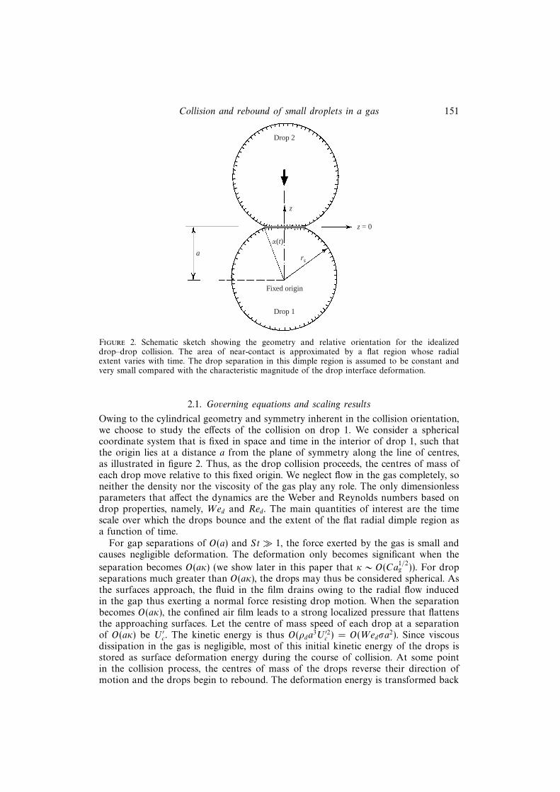
Figure 2. Schematic sketch showing the geometry and relative orientation for the idealizeddrop–drop collision. The area of near-contact is approximated by a flat region whose radialextent varies with time. The drop separation in this dimple region is assumed to be constant andvery small compared with the characteristic magnitude of the drop interface deformation.
2.1. Governing equations and scaling results
Owing to the cylindrical geometry and symmetry inherent in the collision orientation,we choose to study the effects of the collision on drop 1. We consider a sphericalcoordinate system that is fixed in space and time in the interior of drop 1, such thatthe origin lies at a distance a from the plane of symmetry along the line of centres,as illustrated in figure 2. Thus, as the drop collision proceeds, the centres of mass ofeach drop move relative to this fixed origin. We neglect flow in the gas completely, soneither the density nor the viscosity of the gas play any role. The only dimensionlessparameters that affect the dynamics are the Weber and Reynolds numbers based ondrop properties, namely, Wed and Red. The main quantities of interest are the timescale over which the drops bounce and the extent of the flat radial dimple region asa function of time.
For gap separations of O(a) and St� 1, the force exerted by the gas is small andcauses negligible deformation. The deformation only becomes significant when the
separation becomes O(aκ) (we show later in this paper that κ ∼ O(Ca1/2g )). For drop
separations much greater than O(aκ), the drops may thus be considered spherical. Asthe surfaces approach, the fluid in the film drains owing to the radial flow inducedin the gap thus exerting a normal force resisting drop motion. When the separationbecomes O(aκ), the confined air film leads to a strong localized pressure that flattensthe approaching surfaces. Let the centre of mass speed of each drop at a separationof O(aκ) be U ′c. The kinetic energy is thus O(ρda
3U ′2c ) = O(Wedσa2). Since viscous
dissipation in the gas is negligible, most of this initial kinetic energy of the drops isstored as surface deformation energy during the course of collision. At some pointin the collision process, the centres of mass of the drops reverse their direction ofmotion and the drops begin to rebound. The deformation energy is transformed back

152 A. Gopinath and D. L. Koch
into kinetic energy and the rebound process is complete when the drops are againseparated by a distance large compared to O(aκ).
For the deformation energy to balance the O( 43πρda
3U ′2c ) initial kinetic energy, the
characteristic magnitude of the interface deformation should scale as O(aWe1/2d ). The
pressure exerted in the dimple region is 2σ/a. The time scale for the drops to translatethrough a distance of O(a) is O(a/U ′c) whereas the time for the deformation to relax
is much smaller being O(aWe1/2d U ′−1
c ). This is also the time over which the centre ofmass velocity changes sign and the rebound occurs. Balancing the overall force withthe rate at which the centre of mass velocity changes indicates that the radial extentof the dimple scales as O(aWe
1/4d ). This scaling is thus consistent with the O(aWe
1/2d )
deformation and the O(aWe1/2d ) distance the centroid of the drops translate through
during the bounce.The flow field inside the drop may be described by the Navier–Stokes equation
supplemented with the criterion that the velocity field is divergence free. We scaleall lengths with the undeformed drop radius a, drop velocity with the characteristic
velocity of approach when collision begins, U ′c and time with aWe1/2d U ′−1
c . For colli-sions of interest, drop Reynolds numbers are usually greater than one and the Webernumber is very small, so viscous effects are negligible. Furthermore, since St� 1, weanticipate that the dynamic pressure in the drop will scale as O(ρdU
′2c We
−1/2d ) and use
this as the characteristic deformation-induced dynamic pressure. The Navier–Stokesequation for the fluid velocity u and pressure pd in the drops reads:
∂ud∂t
+We1/2d ud · ∇ud = −∇pd +
We1/2d
Red∇2ud +
We1/2d
Frg (2.1)
where in equation (2.1), Fr ≡ U ′2c /ag is the Froude number and g is the unitvector along which gravity (of magnitude g) acts. In most collisions of interest,We
1/2d /Red � 1, i.e. the O(a2ρd/µd) time scale for viscous diffusion of momentum in
the drop is much larger than the O(aWe1/2d /U ′c) bounce time. The Froude number
is typically large for these collisions because the fluid acceleration is greater than gduring most of the collision. Taking the terminal velocity as a typical relative velocityindicates that the Froude number is large whenever the Stokes number is large. Thus,we will neglect gravity in our analysis, i.e. we set the Froude number to infinity. Sincethe gravity term is absent and the viscous term is typically negligible compared to theinertia terms, the equation of motion reduces to the unsteady, linear form:
∂ud∂t
= −∇pd. (2.2)
The pressure gradient generated in the drop due to the impulsive nature of thecollision is balanced by drop inertia. Note that all velocities, forces and positionvectors are measured in the stationary inertial reference frame.
The fluid in the drop undergoes inviscid impulsive motion owing to the deformationof the bounding surface. This deformation produces instantaneous pressure gradientswhich cause instantaneous changes in the fluid velocity. The initial state is assumedto be an undeformed drop so that the initial vorticity is everywhere zero. The tractiongenerated by the ambient gas on the drop surface is a source of vorticity. WhenRed � 1, the effect of these tangential stresses is confined to a very small boundarylayer of O(aRe
−1/2d We
1/4d ) close to the surface during the O(aWe
1/2d U ′−1
c ) time it takesfor the bounce to occur. Thus, we may assume that the flow in the interior of the drop

Collision and rebound of small droplets in a gas 153
is irrotational. Furthermore, the pressure drop across this boundary layer generateddue to viscous effects is small compared to that generated by the impulsive motion ofthe drop. Equation (2.1) also indicates that the viscous terms are in fact less importantthan the nonlinear inertial terms when Red � We
1/2d . Consequently, we expect drop
viscosity to have negligible effects on the rebound process.In the analysis that follows, we will assume that there is a localized pressure of
O(2σ/a) acting over a flat region of angular extent α. Thus, the gas pressure can bewritten as
p′g = p′∞ + 2σ
aH(α− θ),
H(z) being the Heaviside step function. Equation (2.2) allows us to write the pressureinside the drop in the form:
p′d = p′∞ + 2σ
a+ A′(t)− ρd
(∂φ′
∂t′
)s
,
where A′(t) is a function of time. The O(aWe1/2d ) surface deformation is caused by the
localized pressure 2σ/a acting in the region around the centreline. Initially, when theundeformed drops begin their approach, the angular extent of the dimple region, α,is zero. As the drops come closer, the pressure flattens an increasing portion of thesurface and hence the radial extent will evolve with time.
We now write the velocity field as the gradient of a potential function, φ whichsatisfies Laplace’s equation,
ud = ∇φ.Thus,
∇2φ = 0, (2.3)
owing to the incompressibility of the fluid in the drop. To see this, we note that thereare no sources of mass or momentum inside the drop. Equation (2.3) also impliesthat ∫
Vd
∇2φ dVd = 0 =
∫Ad
((∇φ)s · ns) dAd
where Vd and Ad stand for the volume and surface of the drop, respectively. As faras the fluid inside the drop is concerned, the flat dimple region looks like a pointsince its radial extent is only O(aWe
1/4d ) compared to the O(a) extent of the drop.
The development of the flat region displaces a mass of fluid that is O(ρda3Wed). This
is an O(Wed) fraction of the total mass of the drop. In the analysis that follows, wewill enforce the volume constraint in the drop to O(We
1/2d ) with errors of O(Wed) and
so the effects of this flat region can be neglected in formulating the equation for thevelocity potential in the drop. We also note that the near-contact region is assumedto remain flat. Hence, as the centroids of the drops become closer to each other, inorder to keep the volume constant, the drops bulge at their equators.
Without loss of generality, we may set the constant A′(t) to zero for all time. Thisis permitted since φ and dφ/dt are defined to arbitrary constants which may bechosen to make A′(t) zero. This result is also obtained by matching φ in the outerand inner regions. The most general solution for the velocity potential is thus a linearsuperposition of growing spherical harmonics. Note that φ and its derivatives haveto be finite at the origin of the spherical coordinate system. The boundary conditionsthat must be imposed are the kinematic condition at the drop interface,
(∇φ)s · ns = U s · ns, (2.4)

154 A. Gopinath and D. L. Koch
where ns is the outward unit normal at the drop surface (represented by s). Thisimposes the constraint that the interface is a material surface and fluid elements onthe interface remain on it at all times. Since the only normal stresses are due to theliquid and gas pressures, the normal stress balance reduces to the Young–Laplaceequation,
(p′d − p′g)s = σ(∇′ · n′)s. (2.5)
Let r∗ be the position vector of a point as measured from the fixed origin (in theinterior of drop 1) and η = cos θ. Then we have,
r∗s (η, t) = aR(η, t) = a[1 +We1/2d H(η, t)].
The expression on the right-hand side of equation (2.5), i.e. the curvature termrepresenting the pressure drop across the interface due to surface tension, may thenbe written in dimensionless form as:
ΥR =−([(1− η2)Rη]η − 2R)R + η(1− η2)[R3
ηR−1] + 3(1− η2)(Rη)
2
[R2 + (1− η2)(Rη)2]3/2,
the subscripts η denoting differentiation with respect to η. Substituting the expressionfor R we obtain the much simplified linearized form for the curvature term valid forsmall deformations:
ΥoH = −2H− d
dη
[(1− η2)
dHdη
].
The axisymmetric collision geometry and the structure of the operator Υo indicatethat we can write H as (see Appendix A):
H(η, t) =
∞∑k=0
Dk(t)Pk(η), (2.6)
where η = cos θ and Pk(η) is the Legendre function of order k. Imposition ofthe constraint that the drop volume is constant at all times, shows that the modecorresponding to a uniform volumetric change, Do(t) = 0. Also, the velocity of thecentre of mass of the drop is given by dD1/dt and the rate at which this changes isrelated to the overall force acting on the drop.
The size of the transition region intermediate between the dimple and outer regionsmay be estimated easily as O(aCa
1/4g ). For the inner region to be approximately flat,
we require that the O(a2 sin2 α/κ) radius of curvature of the dimple be much largerthan a. Finally, we note that the area of the transition region over which the curvaturechanges from infinity to a value of O(a−1) is given by O(aCa
1/4g ) and is much less than
the O(aWe1/4d ) size of the flat region.
Geometric considerations indicate that the area of closest approach may be ap-proximated as a circle and so α, the half-angle subtended by the flat region at thedrop centre, is given by:
1 +We1/2d
∞∑k=1
Dk(t)Pk(cos α) = (cos α)−1. (2.7)
Let er and eθ be the unit surface vectors along the radial and tangential directions,respectively. Using, ns ≈ er + O(We
1/2d )eθ , we can write the radius of curvature as:
(∇′ · n′)s =2
a+
1
aWe
1/2d
∞∑k=1
(k2 + k − 2)Dk(t)Pk(η).
Collision and rebound of small droplets in a gas 155
The solution for φ valid away from the inner flat region which satisfies the symmetryconditions and is bounded for all points within the drop is given by
φ =
∞∑k=0
Bk(r∗)kPk(η). (2.8)
Substituting (2.6) and (2.8) in the kinematic condition (2.4), and using the orthog-onality properties of Legendre polynomials gives us one relationship between Bk(t)and Dk(t) valid for k > 1:
dDkdt
= kBk. (2.9)
The second equation relating the two sets of unknown coefficients can be obtained bysubstituting the expansions for the deformation and velocity potential in the normalstress boundary condition. This gives us the Young–Laplace equation of the form(k > 1):
dBkdt
= −We−1/2d [Pk−1(cos α)−Pk+1(cos α)]− [k(k + 1)− 2]Dk. (2.10)
Equations (2.9) and (2.10) along with equation (2.7) for the extent of the inner regionserve to define the problem fully. Thus, the force in the inner region drives a potentialflow inside the drop which then controls surface deformation and the extent of theflat region.
Tsao & Koch (1994) studied the rebound process for low-Weber-number, high-Reynolds-number bubbles colliding in a liquid to which ionic salts have been added.The addition of dissociating salts creates a strong hydration repulsive force that actswhen the bubbles are nearly touching and keeps the near-contact interfaces separated(thus this repulsive force is analogous to the force exerted by the pressure in thegas film). The inertia of the liquid outside the bubbles was taken into considerationand the flow outside the bubbles was modelled using potential flow theory. Thequalitative behaviour of the drop bounce is similar to that of the bubble bounce, infact, when ln(We
1/4d ) � 1, the analytical expressions for the bouncing times and the
radial extent of the dimple region are the same. This is essentially due to the potentialflow formulation.
As Wed → 0, we anticipate that more modes must be included for accuratenumerical resolution of the deformation. Combining equations (2.9) and (2.10) givesus the following second-order differential equation for Dk(t):
d2Dk
dt2= −k[k(k + 1)− 2]Dk − kWe
−1/2d [Pk−1(cos α)−Pk+1(cos α)], (2.11)
for k > 1. Analysis of the k � 1 modes shows that for 1� k � α−1,
Dk ≈ −We−1/2d
[2k + 1
2k2
(α2 − α4
12
)− k(k + 1)(2k + 1)
16k2α4
], (2.12)
and for k � α−1
Dk ≈ −We−1/2d
k5/2
(8 sin α
π
)1/2
sin[(k + 12)α− 1
4π]. (2.13)
Thus, for a fixed value of the Weber number, kα � 1, Dk ∼ k−1 and for kα � 1, Dkdecays faster than O(We
−1/2d sin α1/2k−5/2). Note that when k ∼ O(α−1), the deformation
156 A. Gopinath and D. L. Koch
Dk is O(α). We would need to keep terms k ∼ O(We−1/4d ) to describe the deformation
close to the inner region. Equation (2.11) indicates that higher-order deformationmodes have a leading O(k−2) component that is in quasi-equilibrium with the forcingpressure, namely, the [Pk−1(cos α)−Pk+1(cos α)] term. These modes also have a smallO(k−3) component that oscillates with a large O(k3/2/2π) frequency. For very smallWeber numbers, the time scale of the bounce is much larger than the period ofoscillation of these high-frequency components and hence the large modes of surfacedeformation are essentially in equilibrium with the driving force.
We note that the initial-value problem of determining the droplet deformationand the evolution of the interface shape with time is, in principle, solvable usinga known set of eigenvalues and the associated normal modes for each value ofthe Weber number. The deformation can be written as a linear superposition ofthe corresponding non-degenerate eigenvalues. Clearly, in the case of zero net force(i.e. the dimple extent is always zero), the free-surface oscillations are solely due tocapillary effects with the net surface energy being conserved.
2.2. Analytical solutions when ln(We−1/4d )� 1
The equations described in the previous section are obtained by neglecting higher-order terms thus leading to algebraic errors of O(We
1/4d ). A completely analytical
approach, albeit with larger logarithmic errors is possible when ln(We−1/4d ) � 1.
However, comparison of results obtained by this asymptotic analysis to the exactnumerical and simulation results shows the approximate theory to be valid over asurprisingly large range of Weber numbers.
Expressions (2.6) and (2.12) indicate that the sum of the deformation modes
1� k �We−1/4d gives a logarithmic term of O(ln(We
−1/4d )) for the scaled deformation.
In other words, as the Weber number becomes asymptotically small, the length scaleof the translational mode is different from that of the other surface deformationmodes by a logarithmic factor. Thus, the flow driven by deformation modes can beneglected when compared to that driven by the primary translational mode. The mainvariable controlling the dynamics is the instantaneous force acting on the drop thattends to change its centre of mass velocity. In view of these observations, we nowrewrite the equation for the position vector on the drop surface as follows:
rs(η, t) = 1 + δ1D∗1(t)P1(η) + δ2
∞∑k=2
D∗k(t)Pk(η). (2.14)
Here, δ1 and δ2 are small parameters which were assumed to be equal to We1/2d in
our previous analysis. Consider the energy balance that describes the conversion ofinitial kinetic energy of the drop into deformation energy. The total energy stored assurface deformation energy is the area integral of the sum of the deformation modes.For all the initial kinetic energy to be stored as deformation energy, this area integralshould be O(Wed). A rough argument assuming that all modes scale similarly wouldindicate that deformation modes are O(We
1/2d ), thus giving the O(Wed) estimate for
the energy stored as deformation energy. For asymptotically small Weber numbers,the equations obtained previously indicate that the sum of modes k � 1 gives a
term that is O(ln(We−1/4d )) larger than expected. This means the magnitude of these
higher modes should be O([Wed/ ln(We−1/4d )]1/2) instead of We
1/2d to obtain the correct
global energy scaling. We thus see that to leading order, δ1/δ2 ∼ ln(We−1/4d ) � 1.
Equating the inertia of the drop to the net force exerted by the localized pressure
Collision and rebound of small droplets in a gas 157
gives δ1δ2 = Wed. Analytical expressions for δ1 and δ2 can be obtained by combiningthe scaling from the force balance with the scaling from the surface energy balance.This yields
δ1 = We1/2d ln1/2 We
−1/4d
[1 + O
(ln1/2 ln1/4 We
−1/4d
ln1/2 We−1/4d
)].
and
δ2 =We
1/2d
ln1/2 We−1/4d
[1 + O
(ln1/2 ln1/4 We
−1/4d
ln1/2 We−1/4d
)].
The extent of the inner flat region is obtained from force balance arguments and is
O(δ1/22 ). Re-scaling the time for the bounce by aU ′−1
c δ1 and using (2.8) and (2.14) in(2.4) we obtain:
dD∗1dt∗
= B1,δ2
δ1
dD∗kdt∗
= kBk (∀ k > 2). (2.15)
The deformation modes 1 � k � α−1(t∗) are in quasi-steady equilibrium with theforcing in the inner region and are given by:
D∗k(t∗) ≈ −α2∗(t∗)k
+ O
(1
k2
), (2.16)
where, α∗ is the scaled radial extent of the inner region written thus:
α∗(t∗) = α(t∗)[We
δ1
]−1/2
= α(t∗)δ−1/22
An overall force balance on the drop gives
d2D∗1dt2∗
=dB1
dt∗= − 3
2α2∗(t∗). (2.17)
The same result can be obtained by simplifying the normal stress balance, namely,the Young–Laplace equation. The radial extent of the inner region is coupled directlyto the translational mode since the other modes of fluid motion driven by thedeformation are small in the limit Wed → 0. The fluid motion inside is primarilycontrolled by the local applied pressure (forcing). In the limit of small α, the radialextent is determined to leading order by the translation mode and also the sum ofhigher-order modes. Indeed, a Taylor series expansion of (2.7) for small α indicatesthat:
α2∗(t∗) = D∗1(t∗). (2.18)
The contribution from modes k � 1 is as important as that from the k = 1 mode,but much larger than that from other k ∼ O(1) modes. The bounce time defined asthe time it takes for the drops to rebound back to their initial separation is given by
t′b = π√
23aU ′−1
c δ1. (2.19)
Using the initial conditions for the deformation and flow modes, we obtain thefunctional forms for B1 and D∗1:
B1(t∗) = cos
(√32t∗), D∗1(t∗) =
√23
sin
(√32t∗)
(2.20)
158 A. Gopinath and D. L. Koch
Thus,
D′1,max ≈√
23aWe
1/2d ln1/2 (We
−1/4d ). (2.21)
The total dimensional force, F ′(t′), acting on the drop from the 2σ/a pressure actingover the flat region of radial extent α(t∗) is:
F ′(t′) = 2πρdU′c2a
2δ−11 α2
∗(t′) ∼ O
(2σ
aa2δ1
). (2.22)
Clearly, in this asymptotic limit, the maximum force occurs when the flat region hasthe maximum radial extent. We also note that the localized force is assumed to beindependent of the drop velocity. As the collision proceeds, the initial kinetic energyof the drop is converted to the surface deformation energy, kinetic energy of the fluidand work done against the force. However, in the limit ln(We
−1/4d ) � 1, the force
is approximately simple harmonic in nature and is hence conservative. This leading-order approximation indicates that all the energy expended in deforming the surfaceis converted back to the kinetic energy of the drop when the collision is complete.This, however, is only an approximation as the rebound process and approach arenot symmetric when k ∼ O(1) modes are considered and this asymmetry becomesmore pronounced as the Weber number increases. The kinetic energy at time t = 0 is23πρda
3U ′2c . At any arbitrary time during the approach or rebound, the kinetic energyin the fluid is given by:
E ′KE = 12ρd
∫V ′d
(∇′φ′)2 dV ′. (2.23)
Using the analytical expressions obtained in this section, we can write
E ′KE(t∗)E ′KE(0)
= cos2
(√32t∗). (2.24)
2.3. Numerical results and comparison with existing simulations and experiments
The first-order differential equations (2.9) and (2.10) in conjunction with the algebraicequation (2.7) can be solved simultaneously to obtain the deformation and fluidmodes. We start the collision when the drops are separated by a distance equal to 2a.The initial conditions are taken to be:
Dk>1(t = 0) = 0, Bk>2(t = 0) = 0, B1(t = 0) = 1.
The dimensionless centre-to-centre distance between the drops at any instant in time
is given by 2(1−We1/2d D1(t)).
Numerical solutions were obtained as follows. We chose a value of N∗ and retainedterms 1 6 k 6 N∗ in the expansions to obtain a finite system of equations forthe unknown coefficients. The resulting equations were solved by a second-orderpredictor–corrector method. The value of N∗ was varied until convergent results(within variations of 1%) were obtained for the variables of interest. The temporalevolution of the drop deformation, fluid motion and dimple extent was followed.Finally, the calculations were terminated when the drop reached its initial position,i.e. the drops were separated by a distance equal to 2a. This procedure was repeatedfor various values of the Weber number.
The equations for Dk indicate that a very large number of nodes k ∼ O(We−1/4d )
are required to resolve accurately the deformation and fluid flow inside the drop.As Wed → 0, we would need to solve a very large and stiff set of nonlinearequations. In order to avoid this, we use expressions (2.12) and (2.13) to simplifythe numerical solution. We split the set of equations into two sets: the first for
Collision and rebound of small droplets in a gas 159
1 6 k 6 N =∼ O(We−1/4d ) and the other for k > N. For the latter equations, we
use the asymptotic expressions for Dk presented earlier while explicitly solving forthe deformation modes for 1 6 k 6 N. This procedure was used to obtain results forWeber numbers less than 10−4. For Weber numbers O(10−4)–O(10−3), we used theasymptotic expressions and also solved the system using a large number of modes.Both methods yield identical results.
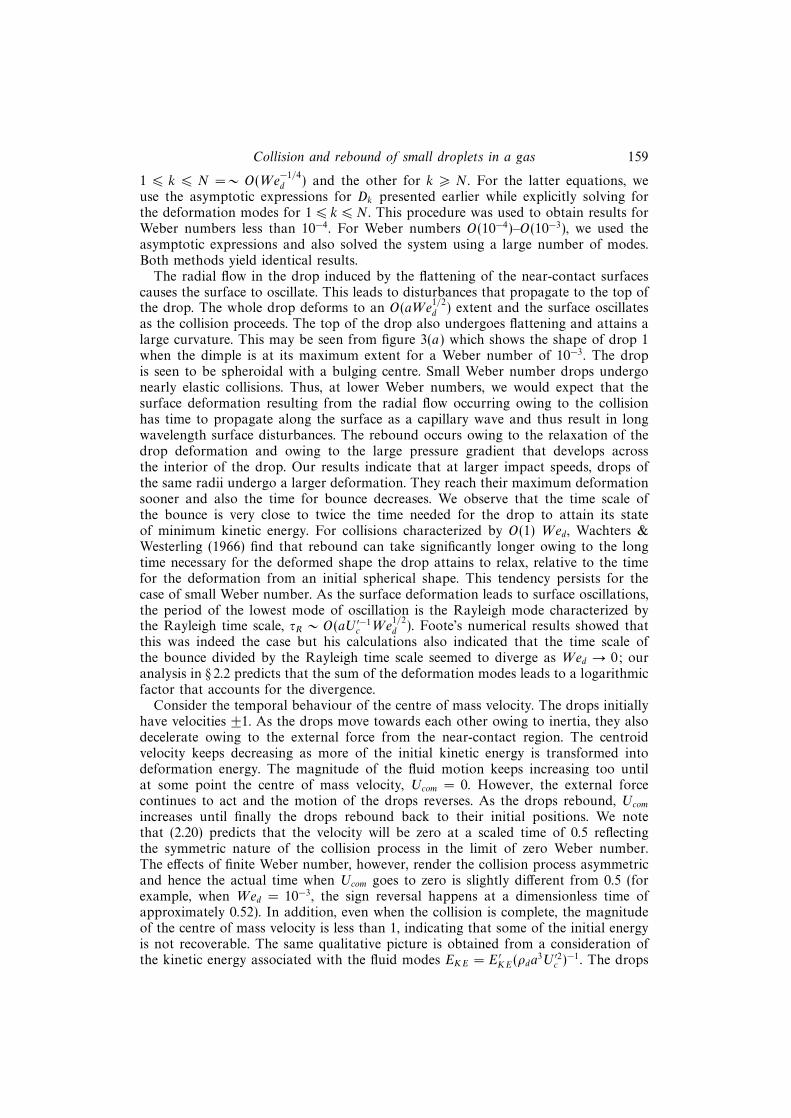
The radial flow in the drop induced by the flattening of the near-contact surfacescauses the surface to oscillate. This leads to disturbances that propagate to the top ofthe drop. The whole drop deforms to an O(aWe
1/2d ) extent and the surface oscillates
as the collision proceeds. The top of the drop also undergoes flattening and attains alarge curvature. This may be seen from figure 3(a) which shows the shape of drop 1when the dimple is at its maximum extent for a Weber number of 10−3. The dropis seen to be spheroidal with a bulging centre. Small Weber number drops undergonearly elastic collisions. Thus, at lower Weber numbers, we would expect that thesurface deformation resulting from the radial flow occurring owing to the collisionhas time to propagate along the surface as a capillary wave and thus result in longwavelength surface disturbances. The rebound occurs owing to the relaxation of thedrop deformation and owing to the large pressure gradient that develops acrossthe interior of the drop. Our results indicate that at larger impact speeds, drops ofthe same radii undergo a larger deformation. They reach their maximum deformationsooner and also the time for bounce decreases. We observe that the time scale ofthe bounce is very close to twice the time needed for the drop to attain its stateof minimum kinetic energy. For collisions characterized by O(1) Wed, Wachters &Westerling (1966) find that rebound can take significantly longer owing to the longtime necessary for the deformed shape the drop attains to relax, relative to the timefor the deformation from an initial spherical shape. This tendency persists for thecase of small Weber number. As the surface deformation leads to surface oscillations,the period of the lowest mode of oscillation is the Rayleigh mode characterized bythe Rayleigh time scale, τR ∼ O(aU ′−1
c We1/2d ). Foote’s numerical results showed that
this was indeed the case but his calculations also indicated that the time scale ofthe bounce divided by the Rayleigh time scale seemed to diverge as Wed → 0; ouranalysis in § 2.2 predicts that the sum of the deformation modes leads to a logarithmicfactor that accounts for the divergence.
Consider the temporal behaviour of the centre of mass velocity. The drops initiallyhave velocities ±1. As the drops move towards each other owing to inertia, they alsodecelerate owing to the external force from the near-contact region. The centroidvelocity keeps decreasing as more of the initial kinetic energy is transformed intodeformation energy. The magnitude of the fluid motion keeps increasing too untilat some point the centre of mass velocity, Ucom = 0. However, the external forcecontinues to act and the motion of the drops reverses. As the drops rebound, Ucom
increases until finally the drops rebound back to their initial positions. We notethat (2.20) predicts that the velocity will be zero at a scaled time of 0.5 reflectingthe symmetric nature of the collision process in the limit of zero Weber number.The effects of finite Weber number, however, render the collision process asymmetricand hence the actual time when Ucom goes to zero is slightly different from 0.5 (forexample, when Wed = 10−3, the sign reversal happens at a dimensionless time ofapproximately 0.52). In addition, even when the collision is complete, the magnitudeof the centre of mass velocity is less than 1, indicating that some of the initial energyis not recoverable. The same qualitative picture is obtained from a consideration ofthe kinetic energy associated with the fluid modes EKE = E ′KE(ρda
3U ′2c )−1. The drops

160 A. Gopinath and D. L. Koch
Undeformeddrop
180°
150°
120°90°
60°
30°
0°
Flatdimpleregion
Fixedorigin
Direction of collision
101
(b)
100
t b
(a)
10–6 10–5 10–4 10–3 10–2 10–1 100
0.8
0.7
0.6
0.5
0.4
0.3
0.2
0.1
010–6 10–5 10–4 10–3 10–2 10–1 100 101
(c)
Wed
(r! d/a
) max
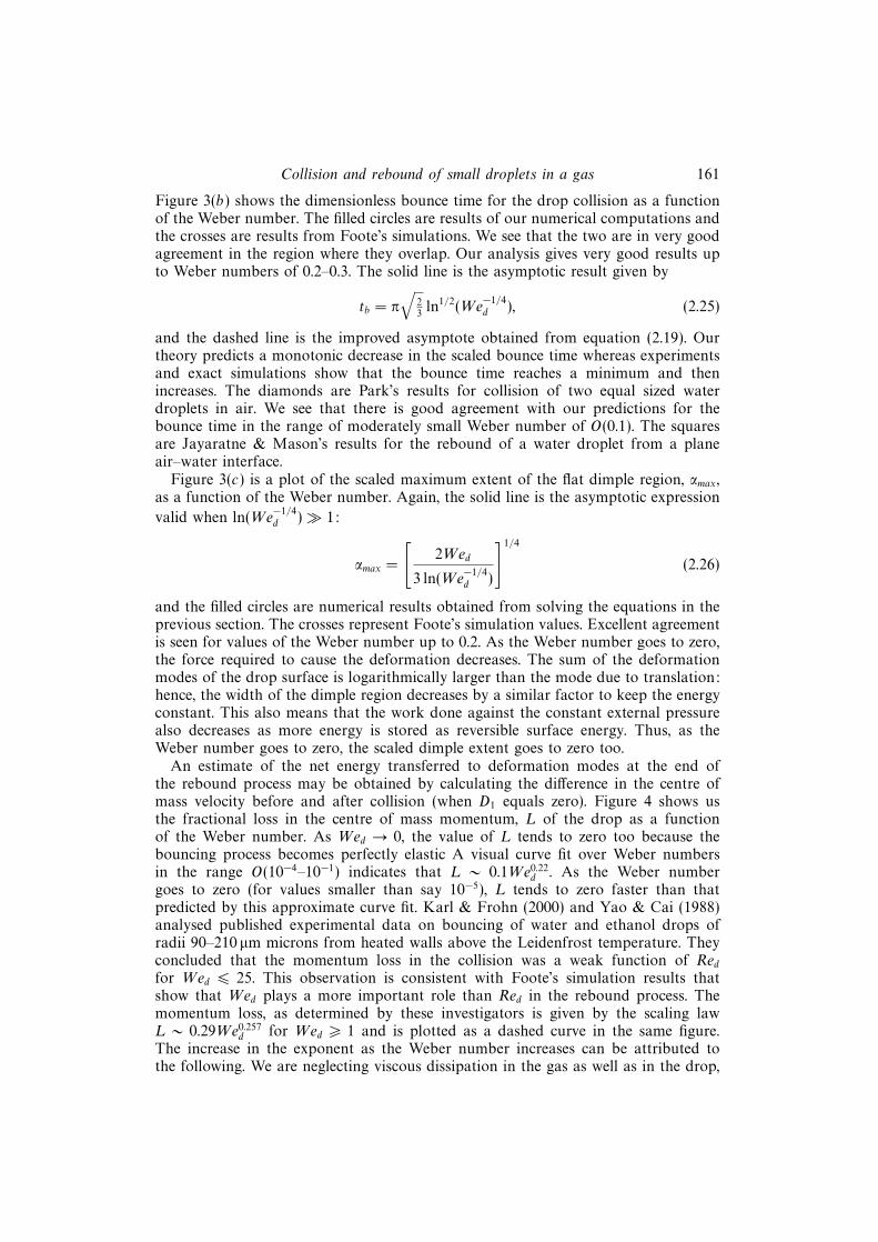
Figure 3. (a) The shape of drop 1 when the flat dimple region attains its maximum radial extent.The Weber number is 10−3. The radial distances from the fixed origin (in drop 1) to the interfaceare scaled by a. The solid curve is the actual drop shape while the dashed curve represents theundeformed drop. Only half of the domain is shown since the shape is axisymmetric. (b) The scaledbounce time, tb, as a function of the Weber number. •, our numerical results; ×, Foote’s simulationresults. The dashed and the solid curves represent asymptotic expansions valid for small Webernumber. �, results from experiments by Park (1970); �, experimental results from Jayaratne &Mason (1964). (c) Scaled maximum extent of the flat dimple region as a function of the Weber
number, Wed. The solid line is the asymptotic expression valid when ln(We−1/4d )� 1. •, numerical
results obtained from solving the equations in the previous section. ×, Foote’s simulation values.
remain deformed and undergo shape oscillations even when they have reboundedback to their initial separations. Our results also show that the minimum values ofthe the kinetic energy and |Ucom| are attained at different times.
The main variables predicted from this potential flow analysis that can be comparedto existing simulations by Foote (1975), and experiments by Jayaratne & Mason (1964)and Park (1970) are the time scales over which the drop bounce occurs (or equivalentlythe total time of apparent contact) and the maximum extent of the flat dimple region.
Collision and rebound of small droplets in a gas 161
Figure 3(b) shows the dimensionless bounce time for the drop collision as a functionof the Weber number. The filled circles are results of our numerical computations andthe crosses are results from Foote’s simulations. We see that the two are in very goodagreement in the region where they overlap. Our analysis gives very good results upto Weber numbers of 0.2–0.3. The solid line is the asymptotic result given by
tb = π√
23
ln1/2(We−1/4d ), (2.25)
and the dashed line is the improved asymptote obtained from equation (2.19). Ourtheory predicts a monotonic decrease in the scaled bounce time whereas experimentsand exact simulations show that the bounce time reaches a minimum and thenincreases. The diamonds are Park’s results for collision of two equal sized waterdroplets in air. We see that there is good agreement with our predictions for thebounce time in the range of moderately small Weber number of O(0.1). The squaresare Jayaratne & Mason’s results for the rebound of a water droplet from a planeair–water interface.
Figure 3(c) is a plot of the scaled maximum extent of the flat dimple region, αmax,as a function of the Weber number. Again, the solid line is the asymptotic expression
valid when ln(We−1/4d )� 1:
αmax =
[2Wed
3 ln(We−1/4d )
]1/4
(2.26)
and the filled circles are numerical results obtained from solving the equations in theprevious section. The crosses represent Foote’s simulation values. Excellent agreementis seen for values of the Weber number up to 0.2. As the Weber number goes to zero,the force required to cause the deformation decreases. The sum of the deformationmodes of the drop surface is logarithmically larger than the mode due to translation:hence, the width of the dimple region decreases by a similar factor to keep the energyconstant. This also means that the work done against the constant external pressurealso decreases as more energy is stored as reversible surface energy. Thus, as theWeber number goes to zero, the scaled dimple extent goes to zero too.
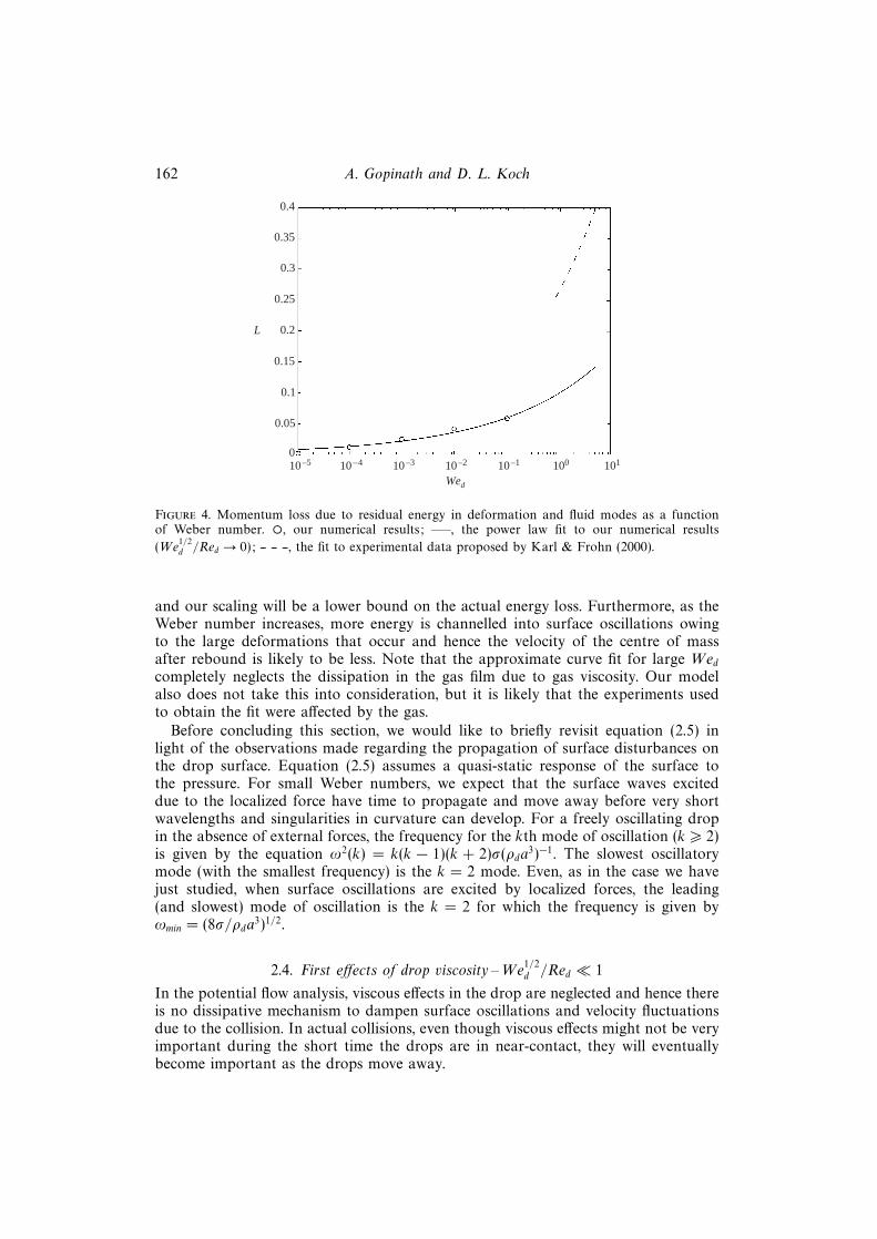
An estimate of the net energy transferred to deformation modes at the end ofthe rebound process may be obtained by calculating the difference in the centre ofmass velocity before and after collision (when D1 equals zero). Figure 4 shows usthe fractional loss in the centre of mass momentum, L of the drop as a functionof the Weber number. As Wed → 0, the value of L tends to zero too because thebouncing process becomes perfectly elastic A visual curve fit over Weber numbersin the range O(10−4–10−1) indicates that L ∼ 0.1We0.22
d . As the Weber numbergoes to zero (for values smaller than say 10−5), L tends to zero faster than thatpredicted by this approximate curve fit. Karl & Frohn (2000) and Yao & Cai (1988)analysed published experimental data on bouncing of water and ethanol drops ofradii 90–210 µm microns from heated walls above the Leidenfrost temperature. Theyconcluded that the momentum loss in the collision was a weak function of Redfor Wed 6 25. This observation is consistent with Foote’s simulation results thatshow that Wed plays a more important role than Red in the rebound process. Themomentum loss, as determined by these investigators is given by the scaling lawL ∼ 0.29We0.257
d for Wed > 1 and is plotted as a dashed curve in the same figure.The increase in the exponent as the Weber number increases can be attributed tothe following. We are neglecting viscous dissipation in the gas as well as in the drop,
162 A. Gopinath and D. L. Koch
0.35
0.3
0.25
0.2
0.15
0.1
0.05
010–5 10–4 10–3 10–2 10–1 100 101
Wed
0.4
L
Figure 4. Momentum loss due to residual energy in deformation and fluid modes as a functionof Weber number. ◦, our numerical results; —–, the power law fit to our numerical results
(We1/2d /Red → 0); -- -- --, the fit to experimental data proposed by Karl & Frohn (2000).
and our scaling will be a lower bound on the actual energy loss. Furthermore, as theWeber number increases, more energy is channelled into surface oscillations owingto the large deformations that occur and hence the velocity of the centre of massafter rebound is likely to be less. Note that the approximate curve fit for large Wedcompletely neglects the dissipation in the gas film due to gas viscosity. Our modelalso does not take this into consideration, but it is likely that the experiments usedto obtain the fit were affected by the gas.
Before concluding this section, we would like to briefly revisit equation (2.5) inlight of the observations made regarding the propagation of surface disturbances onthe drop surface. Equation (2.5) assumes a quasi-static response of the surface tothe pressure. For small Weber numbers, we expect that the surface waves exciteddue to the localized force have time to propagate and move away before very shortwavelengths and singularities in curvature can develop. For a freely oscillating dropin the absence of external forces, the frequency for the kth mode of oscillation (k > 2)is given by the equation ω2(k) = k(k − 1)(k + 2)σ(ρda
3)−1. The slowest oscillatorymode (with the smallest frequency) is the k = 2 mode. Even, as in the case we havejust studied, when surface oscillations are excited by localized forces, the leading(and slowest) mode of oscillation is the k = 2 for which the frequency is given byωmin = (8σ/ρda
3)1/2.
2.4. First effects of drop viscosity –We1/2d /Red � 1
In the potential flow analysis, viscous effects in the drop are neglected and hence thereis no dissipative mechanism to dampen surface oscillations and velocity fluctuationsdue to the collision. In actual collisions, even though viscous effects might not be veryimportant during the short time the drops are in near-contact, they will eventuallybecome important as the drops move away.
Collision and rebound of small droplets in a gas 163
2.4.1. Viscous dissipation due to the primary, inviscid flow
An estimate of the rate of viscous dissipation due to the primary potential flow maybe made easily. Analysis indicates that the rate of energy dissipated due to viscosityin the drop is given by:
Πvis =
[−µd
∫Vdrop
(∇′u′d : ∇′u′d)dV′]
= −U′3c ρda
2
Red$, (2.27)
where,
$ = 2π
∫ π
0
sin θ dθ
∫ 1
0
(∇ud :∇ud)r2 dr + 2πWe1/2d
∫ π
0
sin θ dθ
∫ H(η,t)
0
(∇ud :∇ud) dy,
where y = (r−1)We−1/2d . The expressions for ud and the drop deformation in the above
equation are as given by (2.3) and (2.6). A simple scaling argument indicates that
the net viscous dissipation over the bounce time is roughly O(ρdU′2c a
3We1/2d Re−1
d ). Amore exact analysis using equation (2.27) and the properties of Legendre polynomials
indicates that in the limit ln(We−1/4d )� 1, $ ∼ O(ln−2(We
−1/4d )).
2.4.2. First effects of drop viscosity on rebound process when We1/2d � Red
The first effects of drop viscosity for small values of We1/2d /Red may be incorporated
into the potential flow analysis done in the previous section by including a dissipativeforce in the momentum equation for the fluid modes. Consider the rate at which thetotal energy contained in the fluid modes is dissipated by drop viscosity. Owing to thelinear nature of the governing equations, the viscous dissipation for each mode k canbe calculated independently of other modes. The balance for each mode is given by:
ρdU′3c a
2We−1/2d
(dBkdt
)vis
= −µdaU ′2c (k − 1)(2k + 1)Bk, (2.28)
where the subscript vis indicates that this balance does not take into account theenergy generated due to the force in the inner flat region. (Physically, this equationis obtained by analysis of the total kinetic energy of the drop associated with thevelocity modes Bk . The effects of viscous dissipation are represented via a fictitiousforce that leads to a decrease in the total kinetic energy of the fluid motions inthe drop.) The modified rate at which the velocity modes change due to inclusionof viscous effects can now be obtained by incorporating this energy loss term intoequation (2.10) to get,
dBkdt
= −We−1/2d [Pk−1(cos α)−Pk+1(cos α)]− [k(k+1)−2]Dk−We
1/2d
Red(k−1)(2k+1)Bk.
(2.29)
We note that this scaling for the energy loss is consistent with the O(We1/2d /Red)
term we neglected in the Navier–Stokes equation. Thus, we find that higher-ordermodes, which also have higher frequencies and smaller amplitudes, are dissipatedfaster. In fact, equation (2.29) indicates that the amplitude Bk of the kth mode inthe absence of any energy inputs would decrease exponentially over a time scaleO[(k − 1)−1(2k + 1)−1RedaU
′−1c ]. Clearly, even for the k = 2 mode, viscous decay
occurs over a time scale that is O(We−1/2d Re−1
d ) larger than the time over which thebounce occurs.

164 A. Gopinath and D. L. Koch
In obtaining equations (2.28) and (2.29), we assumed that the governing equationsfor the fluid velocity were linear. Thus, the analysis is strictly applicable when theviscous effect acts as a small perturbation to the inviscid base state, i.e. We
1/2d /Red � 1
and the viscous term is more important than the nonlinear term. Of course, inmost cases of interest (as shown in table 1), the Reynolds number is in the rangeO(0.1) − O(10) so this simple analysis is expected to give a reasonably qualitativepicture of the effects of drop viscosity. It is interesting, however, to note that nonlinearinertial effects are predicted to be more important than viscous effects for moderateand large Reynolds numbers. This is indeed observed to be the case in experimentsand also in Foote’s simulations where the dynamics of the rebound was found to berelatively insensitive to the drop Reynolds number.
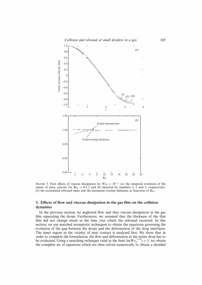
Figure 5(a) shows the centre of mass velocity B1 as a function of dimensionlesstime for Red = 0.5, 2 and 20 and a Weber number of 10−2. As the Reynolds numberdecreases, more of the initial kinetic energy is dissipated and hence the drop speedwhen the rebound process ends follows a decreasing trend. The rebound times increasewith decreasing Red. This is likely to be due to the decrease in the centre of massvelocity compared to the truly inviscid case. However, the magnitude of the changeis very small for the range of Reynolds numbers considered. At t = 0, the distancebetween the drops’ centroids is 2a. As the collision progresses this distance decreases,indicating that if the drops were rigid spheres, they would overlap, i.e. the distancebetween their centres of mass would be less than 2a. We define the magnitude of thedifference between the centroid to centroid distance and 2a as the overlap thickness.Figure 5(b) shows plots of the rebound time (solid line) and the maximum overlapthickness (dashed line), as functions of Red for Wed = 10−2. Both the rebound timesand the overlap thickness are normalized with the corresponding values obtained inthe limit Red → ∞. We find that the degree of maximum overlap decreases slightlyas the Reynolds number decreases. This may be attributed due to increasing viscousdissipation leading to a reduction in the energy available to overcome the forceresisting the relative approach of the drops. As mentioned before, the bounce timeincreases as viscous effects become more important owing to the decrease in the centreof mass velocity. As Red decreases, dissipation becomes important. Consequently, thenet energy available to do work against the constant pressure also decreases.
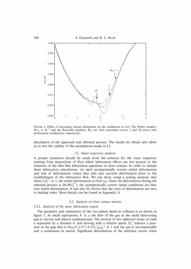
Consider now the temporal evolution of α(t) when drop viscosity is neglected. Thehigher-order deformation modes k � 1 are comprised of a quasi-steady part thatis in equilibrium with the applied force and a smaller, high-frequency componentthat has a small O(2π/k3/2) period. Owing to the coupling between the deformationmodes and the extent of the dimple, as reflected in equation (2.7), these surfacefluctuations cause oscillations in α too. For extremely small values of the Webernumber (say, 10−5), the modes that control the dimple area are the k = 1 andk � 1 modes. Thus the magnitude of the oscillations in α for Wed = 10−5 aresmaller and have a higher frequency. For the relatively larger Weber number of10−3, the area of the dimple region is controlled by modes that are O(10) and sothe time scale for the bounce is comparable to the time scale characterizing theoscillatory behaviour of these modes. A clearer picture of dissipative effects of dropviscosity on the deformation is seen in figure 6 which shows the temporal evolutionof the radial extent of the dimple as a function of time for a Weber number,Wed = 10−2. The higher-order deformation modes oscillate with smaller amplitudeand larger frequency. When viscosity is introduced, the dissipative mechanism causesa dampening of the oscillations. Equations (2.28) and (2.29) indicate that one mayexpect rapid suppression of the large-frequency, small-amplitude oscillations. Thesmoothing effect increases as the Reynolds number decreases, as is expected.
Collision and rebound of small droplets in a gas 165
0.8
0.6
0.4
0.2
0
–0.2
–1.00 1 2 3 4
t
1.0
(a)
–0.4
–0.6
–0.8
(i)(ii) (iii)
(b)Scaled rebound time
Scaled overlap thickness
1.05
1.00
0.95
0.90
0.852 4 6 8 10 12 14 16 18 20
Red
Cen
tre
of m
ass
velo
city
, W(t
)
Figure 5. First effects of viscous dissipation for Wed = 10−2: (a) the temporal evolution of thecentre of mass velocity for Red = 0.5, 2 and 20 (denoted by numbers 3, 2 and 1, respectively);(b) the normalized rebound times and the maximum overlap thickness as functions of Red.
3. Effects of flow and viscous dissipation in the gas film on the collisiondynamics
In the previous section, we neglected flow and thus viscous dissipation in the gasfilm separating the drops. Furthermore, we assumed that the thickness of the thinfilm did not change much in the time over which the rebound occurred. In thissection, we use matched asymptotic techniques to obtain the equations governing theevolution of the gap between the drops and the deformation of the drop interfaces.The inner region in the vicinity of near contact is analysed first. We show that inorder to complete the formulation, the flow and deformation in the entire drop has tobe evaluated. Using a matching technique valid in the limit ln(We
−1/4d ) > 1, we obtain
the complete set of equations which are then solved numerically to obtain a detailed
166 A. Gopinath and D. L. Koch
0.985
0.980
0.975
0.970
0.9650 1 2 3
t
0.990
cos α
(t)
1.000
0.995
4
20
2
Red = 1
Figure 6. Effect of increasing viscous dissipation on the oscillations in α(t). The Weber number,Wed, is 10−2 and the Reynolds numbers, Red are 1(the smoothest curve), 2 and 20 (curve withpronounced oscillations), respectively.
description of the approach and rebound process. The results we obtain also allowus to test the validity of the assumptions made in § 2.
3.1. Outer trajectory analysis
A proper transition should be made from the solution for the outer trajectorystarting from separations of O(a) where lubrication effects are not present to thesolutions of the thin film lubrication equations at close contact. In order to initiatethese lubrication calculations, we need asymptotically correct initial deformationand rate of deformation values that take into account deformation prior to theestablishment of the lubrication flow. We can show, using a scaling analysis, thatwhen Ca
1/2g � 1, the initial deformation is O(aCag). Since the deformation during the
rebound process is O(aWe1/2d ), the asymptotically correct initial conditions are thus
zero initial deformation. It can also be shown that the rates of deformation are zeroto leading order. More details can be found in Appendix A.
3.2. Analysis of close contact motion
3.2.1. Analysis of the inner lubrication region
The geometry and orientation of the two-sphere head-on collision is as shown infigure 1. At small separations, h′ � a the flow of the gas in the small interveninggap is viscous and almost unidirectional. The motion of two spherical drops of radiia separated by a distance h′ and moving with a relative speed 2U ′c induces a pres-sure in the gap that is O(µgU
′ca/h
′2) if h′U ′cρgµ−1g � 1 and the gas is incompressible
and a continuum in nature. Significant deformation of the interface occurs when
Collision and rebound of small droplets in a gas 167
this lubrication pressure balances the capillary pressure 2σ/a. For an incompress-ible, continuum gas, the characteristic gap width, l, at which deformation becomesimportant is thus l ≡ aCa
1/2g . Note that since Cag � 1, deformation effects become
important only when the gap is small enough that a lubrication type analysis applies.Furthermore, we find that the Reynolds number based on l is much less than one, sothat the flow of the gas is governed by the Stokes equations. Since we are interestedin effects of deformation, we choose l as our characteristic axial length scale. Thecharacteristic radial length scale in the region of close contact is taken to be (al)1/2.We choose the initial velocity U ′o when the lubrication calculations are started as ourcharacteristic axial velocity scale. Since St > 1, this choice allows us to relate ourtheoretical predictions with simulation and experimental results that are formulatedin terms of the velocity prior to the collision process. Velocities in the radial directionare scaled by U ′c(a/l)1/2. As the drops come closer, the surfaces deform and this pro-cess leads to energy being stored as deformation energy. For large Stokes numbers,it is reasonable to expect that the energy stored in the deformation modes will be ofthe order of the initial kinetic energy of the drop, O(ρdU
′2c a
3) = O(a2σWed). Thus, thesurface of the drop is expected to deform by an O(aWe
1/2d ) amount, and we choose
to scale the deformation with this length scale. The time scale of the collision processis very small and the characteristic acceleration of the centre of mass of each dropwill be O(U ′2c We
−1/2d a−1), and much greater than the acceleration due to gravity and
so gravity effects on the total force can be ignored for most of the collision. Forstrongly or moderately bouncing drops, the collision and bounce time is expected tobe approximately the time it takes for the centre of mass of the drop to travel avertical distance of the order of the deformation, and so we choose aWe
1/2d U
′−1c as a
characteristic time. The characteristic pressure, pc, used in the scalings is σ/a.The drop surface can be considered tangentially immobile for calculating the gas
flow field, if the tangential velocity of the fluid inside the drop induced due to radialmotion of the gas in the gap is small compared to the radial gas velocity. If the gapthickness at any instant in time is h′, the characteristic size of the region inside thedrop (in the lubrication region) over which gradients of flow and pressure occur isO([ah′]1/2). When h′ ∼ O(aµ2
gµ−2d ), the radial flow of the gas will cause the interface
to move tangentially with velocity of the order of the radial gas velocity. For gapthicknesses larger than this, the drop surfaces are tangentially immobile to leadingorder (Davis, Schonberg & Rallision 1989). Once strong deformation sets in, thecharacteristic spatial extent in the lubrication region over which large gradients inthe drop exist is O(aWe
1/4d ) for St� 1. However, the minimum gap width will still be
O(aCa1/2g ), and so as long as Cag � (µg/µd)
4, the drop interfaces can be consideredtangentially immobile insofar as the gas flow in the thin film is considered. Forwater droplets in air, the viscosity contrast µd/µg is about 100. Taking aCa
1/2g as the
characteristic gap thickness we find that for capillary numbers of O(10−3–10−6) thecriterion derived above is satisfied. We note that at gap separations of O(aCa
1/2g ),
the deformation-induced drop pressure in the lubrication region is O(ρdU′2c Ca
1/4g ).
The pressure generated by the viscous term due to the induced tangential velocity
is O(µdU′cCa
−1/4g /a). Both these terms are much smaller than the pressure in the gas
that is of O(σ/a) if We3/4d � 1 and Ca
3/4g � 1. For Ca
1/2g µd/µg = O(1), the tangential
velocity at h′ = O(aCa1/2) is of the order of U ′c. For smaller capillary numbers, the
tangential interface velocity is O(U ′c) at separations larger than O(aCa1/2g ). Even then,
as far as the gas is concerned, the O(U ′c) tangential velocity is still a factor Ca1/4g
smaller than the mean radial velocity of the gas and hence in order to calculate the
168 A. Gopinath and D. L. Koch
velocity field and pressure in the gap, we can assume zero tangential velocity at thesurface.
We will show later on that the flow inside the drop is potential flow, the viscousterms being negligible for Red �We
1/2d . In most cases, Red � 1, so that viscous effects
are confined to a thin boundary layer near the surface of the drop where the tangentialvelocity adjusts from the value obtained based on the solution of the gas flow to thevalue given by the potential flow solution. The gas flow in the outer region may beneglected to leading order, and so the tangential velocity of the interface induced bythe outer gas flow is small. In the O(aWe
1/2d U ′−1
c ) time it takes for the collision tooccur, the boundary layer that develops in the lubrication region, penetrates into thedrop to an extent given by a(Cag/St)
1/4(µd/µg)1/2. The boundary layer is confined
to the lubrication region as long as the Stokes number, St1/4 � (Ca1/2g µdµ
−1g )1/2. The
normal interface stress resulting from this boundary layer is small compared withthe flow induced drop pressure. Thus, as far as the flow inside the drop in the outerregion is considered, we may model the interface as a stress-free, mobile interface.
We do not include any inter-particle attractive forces and also assume that thereare no surfactants on the interfaces that give rise to surface tension gradients orrepulsive forces. In addition, we also neglect the absorption of gas by the drop. UsingHenry’s law, we can estimate the fractional amount of gas in the gap that is absorbedduring the collision process as O(Dgcst
′c(ah
′cg)−1) and this is typically of the order of10−5 or so. Here, Dg is the gas diffusion coefficient, cs is the molar concentration ofthe gas on the surface, c is the molar concentration of the gas in the gap, h′ is atypical gap width during the collision process that lasts for a time t′c.
In the near contact region (see figure 1b), the two undeformed spheres can beapproximated by paraboloids. The gap extends in the z-direction from H ′1 to H ′2 =−H ′1, where,
H ′1 = − 12H ′ = −
(h′ +
1
2
r′2
a+ D′
), (3.1)
D′ being the deformation in the z-direction measured as indicated in the figure. Thecentres of mass of the spheres move towards one another with speeds U ′1 and U ′2,where, −U ′1 = U ′2 = W ′. The flow of the gas in the gap when the gas behaves asa continuum incompressible fluid is governed by the continuity equation which inscaled form reads:
1
r
∂
∂r(rur) +
∂uz
∂z= 0. (3.2)
The rate at which the centre of mass of drop 2 moves is given by:(Cag
Wed
)1/2dh
dt= W. (3.3)
In the lubrication region, the unit normals to the two surfaces are in the z-direction(to leading order) and, hence, we can write expressions for the rates at which theinterfaces move:(
Cag
Wed
)1/2∂H1
∂t= uz(H1),
(Cag
Wed
)1/2∂H2
∂t= uz(H2). (3.4)
To obtain an equation for the pressure in the gap, we integrate the scaled continuity
Collision and rebound of small droplets in a gas 169
equation over the inter-sphere gap and use equations (3.3) and (3.4):
1
r
∂
∂r(rj) + 2W + 2
∂D
∂t= 0. (3.5)
Here, j is the dimensionless fluid flux per unit circumference out of the gap and isdefined as:
j =
∫ H2
H1
ur dz. (3.6)
To obtain an equation for the flux, we must scale the momentum equations and con-
sider the relative magnitude of the different terms. Since Rel ≡ (aµ−1g U
′cρgCa
1/2g )� 1
and typical values of Rel(Cag/Wed)1/2 are very small, the equation for the radial
pressure gradient reduces to a simple form:
−∂pg∂r
+∂2ur
∂z2= 0.
In the limit of small Rel � 1 and for weakly deforming drops, the pressure gradientalong the gap develops owing to radial motion of the gas out of the gap. Scalearguments indicate that ∂p′g/∂z′, is small compared to radial variations in the pressure.Using this, the momentum equations can be solved for the radial velocity of the gas.We obtain,
ur =1
12
∂pg
∂r[z2 − (H1 +H2)z +H1H2].
From this, we can obtain the following expression for the flux valid for continuumflow:
j = −H3
12
∂pg
∂r. (3.7)
The pressure field satisfies (∂pg/∂r)r=0 = 0 and pg → p∞ for max[1, (Wed/Cag)1/4]� r.
For very large values of the Stokes number, the characteristic radial extent of the
lubrication region scales as aWe1/4d . In deriving these governing equations, we have
used aCa1/4g as the radial scale. An overall force balance on the drop is obtained by
integrating the pressure over the drop surface and this force determines the rate atwhich the velocity of the centre of mass changes:
dW
dt=
3
2
(Cag
Wed
)1/2 ∫ r∞
0
(pg − p∞)r dr. (3.8)
The shape of the air–drop interface is determined by the balance between the exterior(gas) and interior (drop) pressures at the interface and the capillary pressure which isa consequence of the finite interfacial tension and the curvature of the interface. Thestress balance at interface Si of drop i may be written in the form:
p′d,i − p′g − 2µg(ni · e ′ · ni) + 2µd(ni · E ′i · ni) = ±σ(∇′ · ni), (3.9)
p′d is the dimensional drop pressure, while e ′ and E ′ represent the traceless, symmetricparts of the viscous stress tensor in the gas and in the drop, respectively. The unitnormals ±n are chosen such that the pressure inside each non-deformed drop isgreater than that outside by the quantity 2σ/a. Equation (3.9) is valid at all points onthe drop surfaces. In the inner region, however, the two interfaces are nearly planarand parallel to the z = 0 plane and this permits considerable simplification. The

170 A. Gopinath and D. L. Koch
following equation for the deformation of the surface of drop 2 is easily obtained:
1
r
∂
∂r
(r∂D
∂r
)=
(Cag
Wed
)1/2 [p∞ − pg + a
p′d,cσPs
], (3.10)
where, the drop pressure at the interface (p′d)s has been written as p′o + 2σ/a+ p′d,cPs.In equation (3.10), p′d,c is a characteristic fluid pressure induced due to the dropmotion and Ps is the dynamic drop pressure evaluated at the interface. For St > 1,the radial extent of the region inside the drop where strong flow gradients are
induced is O(aWe1/4d ). Since the collision takes place on a time scale O(aWe
1/2d /U ′c),
the characteristic pressure p′d,c in the inner region is O(ρdU′2c We
−1/4d ). In order to be
able to neglect Ps, we want p′d,c � 2σ/a. This criterion gives the condition, We3/4d � 1.
Thus, we find that the deformation in the lubrication region is determined by abalance between the gas pressure in the gap and surface tension forces. In any case,viscous pressure gradients in the drop due to deformation-induced flow in the gapcan be neglected if µdµ
−1g Cag < 1.
Multiplying (3.10) by r and integrating over r using the symmetry condition∂D/∂r = 0 at r = 0 we obtain:
r∂D
∂r= −2
3
dW
dt−(Cag
Wed
)1/2 [∫ r∞
r
(p∞ − pg)r∗ dr∗]. (3.11)
Thus, we obtain the following asymptotic behaviour of D(r, t) as r → r∞:
D(r) ≈ −2
3
dW
dtln r + f(t) + O
((Cag
Wed
)1/2ln r
r2
). (3.12)
In the limit max[Cag,Wed] � 1, we may replace r∞ in the above equations byinfinity without loss of generality. The logarithmic divergence of the deformationindicates that the entire drop deforms and not just the near-contact regions. This maybe contrasted with inertia driven elastohydrodynamic collisions between deformablesolid spheres where the deformation is confined only to the lubrication region andhence analysis of the near-contact region alone provides a description of the collisiondynamics. Our analysis shows that for deformable drops undergoing a collision, sucha local analysis is not sufficient and the deformation of the entire drop has to beconsidered. However, drop–drop collisions are similar to buoyancy driven collisionsof a deformable drop with a rigid or deformable air–water interface. In the latter case,the deformation of the drop and the interface are of the same order. The time scalefor the drop bounce is determined by the rate at which the deformation throughoutthe drop relaxes. Thus, the flow and deformation in the inner region is fully coupledto the flow inside the drop. The divergence of the deformation contrasts with theasymptotic behaviour of the gas pressure for very large values of r which is as follows:
pg − p∞ ≈ 2d2W
dt2ln r
r4−(
1
2
d2W
dt2+ 3W + 3
df
dt
)1
r4. (3.13)
3.2.2. Outer problem for the drop deformation
When r′ � r′∞, the pressure p′g is approximately equal to the bulk value p′∞.Consequently, when the curvature of the interface becomes important, the gas pressurehas nearly decayed to its bulk value and we expect the extent of deformation to bedetermined by a balance between the surface tension (capillary) pressure and the

Collision and rebound of small droplets in a gas 171
pressure induced inside the drop owing to the flow set up by the deformation in thelubrication region. This balance will occur if the characteristic dynamic pressure inthe drop is much greater than the characteristic gas pressure outside the drop. Farfrom the lubrication region, we expect the characteristic gas pressure to scale likeO(µgU
′c/a) and we will find later that the dynamic pressure in the drop scales like
O(ρdU′2c We
−1/2d ). So, as long as Cag �We
1/2d , the effects of gas flow in the outer region
can be neglected. As seen from the outer region, the inner lubrication region shrinksto a point. All details of the pressure profile are lost and the only relevant informationthat is transmitted to the outer region is some sort of averaged information. Theseobservations motivate a simpler treatment of the deformation in the outer region.
It is convenient to use a coordinate system that readily allows us to decouplethe gap thickness from the drop deformation. So we now choose a new sphericalcoordinate system (r∗, θ, φ) with origin at the centre of mass of drop 2, as shown infigure 1(a). This origin, O2, is thus accelerating in a reference frame that is fixed atO1 as shown in figure 1. The spherical coordinate system has its polar axis oriented inthe direction of the acceleration (line of centres) so that the fluid velocity and dropletdeformation in either reference frame is symmetric with respect to the polar axis i.e.∂(.)/∂φ = 0. The droplet surface is at all times during the collision process assumedto be slightly perturbed from its equilibrium value R′ = a.
As seen in the accelerating reference frame, there exists a static pressure gradient inthe gas and in the drop that results from the pseudo-force needed to keep the centreof mass stationary. We retain this force in the momentum balance for the liquid inthe drop since it is of the same order as the leading order inertia terms. In the gas,this induces a pressure that is at most O(ρgaU
′2c We
−1/2d ) on the surface of the drop
and this may be neglected compared to the much larger O(ρdaU′2c We
−1/2d ) dynamic
pressure induced in the drop. In addition, this O(ρgaU′2c We
−1/2d ) pressure term is
smaller than the O(σ/a) pressure that develops in the lubrication region during thebouncing process. Consequently, the gas pressure in this non-inertial frame is thesame as that in the stationary reference frame to leading order.
Let the centre of mass undergo an acceleration
A′com(t′) =dW ′
dt′ez
at any instant in time t′, ez being the unit vector in the z′-direction along the lineof centres. In the accelerating reference frame, the flow inside the drop is governedby the Navier–Stokes equations with a term to account for the pseudo-force due tothe acceleration. Since we are interested in spatial length scales of O(a) (far from thelubrication region), we scale all spatial gradients by 1/a. Fluid velocity u′d is scaledwith U ′c and time t′ is scaled by aWed
1/2/U ′c. The scaled Navier–Stokes equation thenreads:
∂ud
∂t+We
1/2d ud · ∇ud +
p′d,ca∇P =
We1/2d
Red∆ud +
We1/2d
Frd
g
g− aA′comWe
1/2d
U ′2cez. (3.14)
As in § 2, we consider drops for which We1/2d � 1, Frd = U ′2c /ag � 1 and We
1/2d /Red ≡
µd/(ρ′daσ)1/2 � 1. The large Froude number limit implies that gravity effects may be
neglected during the collision process. An examination of the scalings shows that
A′com =
(U ′2c
aWe1/2d
)dW
dt,
172 A. Gopinath and D. L. Koch
and hence the centre of mass acceleration term is also O(1), like the inertia term.Balancing the pressure gradients with inertia gives us the following scaling for thedynamic pressure, p′d,c ∼ O(ρdU
′2c We
1/2d ). The approximate form of the equation of
motion during the collision process attains the form,
∂ud∂t
= −∇pd = −∇P − dW
dtez, (3.15)
and is similar to equation (2.2). Here, P is the dynamic pressure satisfying thecondition P → 0 as ud → 0. This equation represents the impulsive motion of thefluid in the short duration of the collision process.
Let the surface of the drop as measured from the centre of mass of the drop begiven by
r∗s = a(1 +We1/2d D), D(θ, t) =
∞∑k=0
Lk(t)Pk(cos θ). (3.16)
The k = 0 mode corresponds to a volumetric pulsation whereas the k = 1 modecorresponds to the motion of the centre of mass relative to the centre of the coordinatesystem. Imposing the constraint of constant drop volume due to the incompressibilityof the fluid and also the condition that the centre of mass lies at the origin of thecoordinate system, we find both Lo and L1 to be zero for all time. The relativeerrors incurred while imposing the constant volume and centre of mass conditionsare O(Wed) and are small compared to the terms retained. Note that the volumeof the inner dimple region is O(Wed) and thus details of the dimple shape can beneglected in imposing the constant volume constraint. Since vorticity effects may beneglected and the fluid is incompressible, the velocity may be written as the gradientof a velocity potential that satisfies Laplace’s equation in the interior of the drop,
ud = ∇φ, ∆φ = 0. (3.17)
Equation (3.17) presupposes that the potential at the origin (the inner region) isbounded and there is no source of mass/momentum to leading order. A localanalysis of the liquid flow in the inner lubrication region shows that this is indeed the
case. The characteristic length scale in this region is O(aWe1/4d ) and the characteristic
velocities are O(U ′c). Viscous effects can be neglected compared to inertial effects and
so the characteristic pressure is O(ρdU′2c We
−1/4d ), a factor O(We
1/4d ) smaller than the
characteristic pressure in the outer region. The pressure gradients, however, have thesame magnitudes as expected. The characteristic velocity potential in the inner regionis thus O(aU ′cWe
1/4d ), also a factor O(We
1/4d ) smaller than the value in the outer region.
Thus, the velocity potential in the inner lubrication region is small and bounded. Thisimplies that there cannot be a source term on the right-hand side of the Laplaceequation for φ, namely, equation (3.17), since such a source term would imply thatφ is singular at some point inside the drop region. In addition, we note that since φhas to be bounded, we can choose to express both D and φ as a linear superpositionof any complete set of basis functions. We choose the Legendre polynomials as ourbasis functions for convenience.
The governing equations (3.15) and (3.17) are similar to that obtained previouslyfor the idealized bounce problem in § 2. We now write the solution to (3.17) in a formsimilar to (2.8),
φ =
∞∑k=0
Bk(t)(r∗)kPk(cos θ). (3.18)

Collision and rebound of small droplets in a gas 173
Here, r∗ is the scaled radial position as measured from the centre of mass and θ isthe angular position as measured in this new coordinate system. Clearly, both Bo andB1 are zero, owing to the choice of our reference frame.
The dynamic pressure inside the drop can now be written as:
P = −∂φ∂t
+dW
dtr cos θ,
with the rate of change of velocity given by (3.8). Incorporating the expansions forthe deformation and velocity potential in the kinematic interface condition, (2.4), weobtain the following equations relating the two sets of coefficients:
dLk
dt= kBk, k > 2. (3.19)
Here, we used the fact that U s is the velocity of the fluid relative to the centre ofmass velocity evaluated at the particle surface.
The formulation of the problem, as stated above, allows us to obtain anotherrelationship between the pressure inside the drop and the external pressure acting onthe drop. By Newton’s law we can write,
MA′com(t′) =MA′com(t′)ez = −∫Ad
(p′g − p′∞)ns dAd
= −∫Ad
(p′g − p′∞)(ns · ez)ez dAd, (3.20)
where ns is the outward unit normal at a differential surface area dAd of the dropsurface, ez is the unit normal along the z-direction and M is the constant mass ofthe drop. A simple rearrangement of terms and simplification shows that equations(3.8) and (3.20) are exactly identical as Wed → 0. Balancing the capillary pressure dueto the curvature with the pressure drop across the interface we obtain the followingequation,
2D+d
dη
[(1− η2)
dDdη
]= We
−1/2d (pg − p∞) +
∂φ
∂t− dW
dtη + O(We
1/2d D).
Using the fact that D is expressible as a linear superposition of Legendre modes, theabove equation can be rewritten as:
∞∑k=2
dBkdtPk(η) =
dW
dtP1(η)−We
−1/2d (pg − p∞)−
∞∑k=2
(k2 + k − 2)LkPk(η). (3.21)
Multiplying (3.21) by Pm(η) and integrating over η from −1 to +1 we obtain (fork > 2):
dBkdt
= −(k2 + k − 2)Lk − 2k + 1
2We
−1/2d
∫ 1
−1
(pg − p∞)Pk(η) dη. (3.22)
Note that for this equation to be consistent with the expansions assumed for φ andD we need:
dW
dt= 3
2We
−1/2d
∫ 1
−1
(pg − p∞)P1(η) dη.
It can be easily checked that this equation is satisfied in the limit Wed → 0. Inaddition, we also require that the zeroth Legendre moment of the scaled excess gas

174 A. Gopinath and D. L. Koch
pressure be zero, i.e.∫ 1
−1
(pg − p∞)P0(η) dη =
∫ 1
−1
(pg − p∞)η dη = 0.
This equation is satisfied since the component of the excess pressure that is inde-pendent of the angular variable and constant is identically zero. Equations (3.19)and (3.22), when solved simultaneously with appropriate initial conditions, yield thedeformation and velocity profiles. The viscous dissipation in the drop both in theinner and outer regions has been neglected.
3.2.3. Matching and calculation of the unknown function f(t)
In order to obtain a uniformly valid description of the drop deformation wefunctionally match the inner and outer solutions for the deformation and thus obtainf(t). The matching region in terms of the angular variable θ (or in terms of r) satisfiesmax(Ca
1/4g ,We
1/4d )� sin θ � 1, that is, max(1, St1/4)� r � Ca
−1/4g . For a separation
of scales to exist, the asymptotic theory we developed is thus restricted to the rangeof Stokes numbers St � Ca−1
g , i.e. Wed � 1 and is consistent with the assumptionsmade. Seen from the outer region, the inner and matching regions tend to the originr = 0 in the limit of vanishing capillary and Weber numbers. Rewriting equation(3.22) and using the fact that points in the inner region correspond to very smallvalues of θ, we obtain:
dBkdt
= −(k2 + k − 2)Lk
−2k + 1
4π
a
σ
We−1/2
a2
[2π
∫ r′∞
0
(p′g − p′∞)Pk
(1− 1
2
r′2
a2
)(1− 1
2
r′2
a2
)−1
r′ dr′].
Taking the leading expansion of the integrand, we obtain (see Appendix A):
dBkdt
= −(k2 + k − 2)Lk − 2k + 1
3
dW
dt. (3.23)
Equations (3.19) and (3.23) together with appropriate initial conditions are sufficientto determine the values ofLk for all time. Combining the two gives us a second-orderequation for Lk which can be solved exactly. The solution is as follows:
Lk(t) = sin(ωt)c1(k) + cos(ωt)c2(k)− 2k2 + k
3ω
∫ t
0
[dW (t′)
dt′cos(ωt′) sin(ωt)
]dt′
−2k2 + k
3ω
∫ t
0
[dW (t′)
dtsin(ωt′) cos(ωt) dt′
], (3.24)
where, ω(k) = (k3 + k2 − 2k)1/2. The first two terms on the right hand-side representundamped free surface oscillations corresponding to capillary waves on the surfaceof the drop. The constants in these two terms, c1(k) and c2(k) are to be determinedfrom the initial conditions when the force acting on the drop is zero (namely, at
large separations). We note that the deformation has been scaled by aWe1/2d . At large
separations, the deformation of the drop is typically O(aCag) and hence Lk(t = 0) ∼O[(Cag/St)
1/2]� 1. Thus, suitable initial conditions valid when Ca1/2g � 1 and St > 1
are Lk = 0 and dLk/dt = 0 at t = 0. The third and fourth terms on the right-hand
Collision and rebound of small droplets in a gas 175
side of (3.24) represent the direct effect of the force and also the wavelike deformationcreated owing to the forcing. These expressions have a component that is in phasewith the forcing and an oscillatory component that is out of phase. Analysis of (3.24),or equivalently analysis of equations (3.19) and (3.23) in the limit of large n, indicatesthat the deformation modes for large n go as:
Lk(k � 1) ≈ −2
3
dW
dt
1
k+ O
(dW
dtk−2
). (3.25)
Thus, the large deformation modes behave as in the idealized problem dealt with in§ 2 and are in quasi-static equilibrium with the forcing.
Rewriting the expression for the deformation given by the lubrication asymptoteand equating it to the deformation given by the Legendre expansion, we obtain:
−D(θ) =1
3
dW
dtln(Ca−1/2
g ) +2
3
dW
dtln(sin θ)− f(t) = D(θ) =
∞∑k=2
LkPk(cos θ). (3.26)
We now write the sum over all modes as follows using the fact that for large k, wemay replace the summation by an integral:
∞∑k=2
LkPk(η) =
Nc∑k=2
LkPk(η) +
∫ c(sin θ)−1
Nc
LkPk(η) dk +
∫ ∞c(sin θ)−1
LkPk(η) dk, (3.27)
where c is an O(1) constant, η = cos θ and Nc is a cutoff number that satisfies:
1� Nc � c(sin θ)−1.
To evaluate the integrals and obtain a closed form expression for f(t) we mustsubstitute analytical forms for the Legendre polynomials in (3.27). The followingexpressions for the Legendre polynomials are very accurate (see Tsao & Koch 1994)
Pk(cos θ) ≈ 1− 12(k2 + k)(1− cos θ) + 1
16(k2 − 1)(k2 + 2k)(1− cos θ)2, (k sin θ)4 6 64
Pk(cos θ) ≈ cos(kθ + 12θ) + sin(kθ + 1
2θ)√
πk sin θ, (k sin θ)4 > 64
and we use these expressions. This corresponds to choosing the value c = 81/2. In orderto complete the matching procedure we must show that the sum of the deformationmodes has a term that diverges as ln(sin θ). Substituting these asymptotic expressionsfor Pk in (3.27) and simplifying the resulting integrals in the limit θ → 0, we findthat, indeed, in the limit θ → 0 the logarithmically divergent terms match and f(t)is completely specified once the next O(1) term is evaluated. After some algebraicmanipulations we finally obtain
f(t) =dW
dt
[23
ln
(Ca−1/4g
Nc
)+ 0.100 . . .
]−
Nc∑k=2
Lk. (3.28)
The final expression for f(t) is actually independent of Nc provided that Nc lies inthe range of values mentioned above.
A brief note on the errors involved and the range of applicability of this analyticalmatching result is in order. The leading term in the sum of the deformation modesis O(ln(sin θ)). Since the matching region is beyond the dimple region, this leading

176 A. Gopinath and D. L. Koch
term is typically O(ln(We−1/4d )). The higher-order corrections are thus typically O(1),
O(We1/4d ) and so on. When ln(We
−1/4d ) � 1, the neglect of higher-order terms leads
to negligible error and the analytical expression for f(t) is quite accurate. However,when the Weber number is not so small, the higher-order terms cannot be neglectedand a numerical matching has to be performed. The use of the simple analytical form(3.28) can, in such cases, lead to inaccurate and unphysical solutions.
3.3. Collisions of a droplet with a rigid planar wall
A situation encountered in many physical applications is collision of droplets withrigid planar walls. One example is high-pressure sprays where the drops are sur-rounded by a pressurized gas. We can use an analysis similar to that presented thusfar to study the rebound dynamics of the colliding drops in the limit of low impactenergy. In fact, the drop–drop collision may be regarded as a drop–wall collision (thewall being rigid) with a zero stress condition, instead of perfect stick conditions atthe wall. Mathematically, instead of imposing the condition that the velocity be zeroat the wall, we would need to impose the condition that the derivative of the velocityis zero at the wall. Note that we could equivalently use the method of images toformulate the governing equations appropriate for the Stokes flow in this case.
Let the rigid wall be coincident with the z = 0 plane (figure 1a) and consider drop2 with undeformed radius a as the drop undergoing a normal head-on collision withthe wall. We make the scalings as in the drop–drop case. The expression for the gapin the near-contact region is now given by:
Hdw = h+ 12r2 +
(Wed
Cag
)1/2
D. (3.29)
The equations for the flux j, the centre of mass velocity W and the equation forthe deformation D are the same as before. The boundary conditions and the large rbehaviour of D are identical to those obtained for the droplet collision problem. Theonly difference is in the equation for the evolution of the gap size Hdw which has theform:
W +∂D
∂t=
1
12
1
r
∂
∂r
(rH3
dw
∂pg
∂r
). (3.30)
Comparison to the drop–drop case shows that the numerical factor multiplying theright-hand side of (3.30) is different from that in (3.5). This reflects the fact thatonly the drop–gas interface can deform and thus has a non-zero normal velocitycomponent. In fact, a suitable rescaling of the variables and the initial conditionsrenders the two equations for the gap evolution identical. The above equations implythat for large values of r, the pressure profile is given by the following asymptoticrelationship
pg(r � 1) ∼ −12
r4
(W +
∂D
∂t
).
4. Results and discussionThe equations for the gap thickness and the deformation given by (3.5) and
(3.10) form a coupled nonlinear elliptic–parabolic system of equations. The boundarycondition on H , i.e. (3.12), introduces further complications in the attempt to find asuitable convergent and accurate numerical scheme. This is because the deformation

Collision and rebound of small droplets in a gas 177
in the outer region depends on the force acting on the drop and hence the matchingconstant f(t) is also an unknown quantity. Explicit methods to solve the equations inthe incompressible limit and for finite β are not very useful since the stability limit onthe maximum allowable time step ∆t is seen to scale as (∆r)4. Thus, for ∆r ∼ O(10−2)the minimum time increment will be O(10−8) and prohibitively small. An adaptationof the predictor–corrector scheme outlined in our paper for rigid particles (Gopinath,Chen & Koch 1997) showed that this requirement for the largest possible time stepfor obtaining stable solutions was indeed true. This is, in fact, not surprising since theequations we are trying to solve constitute a set of stiff thin-film equations. The simplepredictor–corrector method based on the trapezoidal rule was seen to be second-orderaccurate in time, but it had roughly the stability of the explicit Euler method, i.e.(∆t)min < (∆r)4. Since explicit schemes did not give good results, implicit schemes werethen tried. The completely implicit, iterative scheme used by Davis, Serayssol & Hinch(1986) and also by Yiantsios & Davis (1990) was tried. To guarantee convergencefor very strong deformations, under-relaxation had to be used because of the inversenon-evolutional order of operations employed. This method was seen to work wellfor O(1) values of the Stokes number. However, for large Stokes numbers, a verysmall value of the under-relaxation parameter was required and a prohibitively largenumber of iterations was required to obtain accurate results. Consequently, we useda semi-implicit direct, matrix method based on the algorithm described in Rother,Zinchenko & Davis (1997). This allowed us to obtain stable, accurate solutions using areasonable number of grid points without resorting to extremely small time steps. Theiterative scheme was used to validate and check the accuracy of the matrix inversionresults. Details of the numerical algorithm and the code are given in Appendix B.
We present numerical results for Capillary numbers, Cag = 10−8–10−5. Thesevalues are small enough that meaningful comparisons can be made with the idealizedproblem solved in § 2. At the same time, they represent physically meaningful valuesrepresentative of real collisions. The Stokes numbers we study range from 2 to200. Equations (3.3)–(3.11) indicate that the natural dimensionless quantity thatenters as an independent scaling parameter is not the Stokes number, but rather(Wed/Cag)
1/2 = χ. We present most of our results in terms of Cag and χ. The Stokesnumber is simply 2χ2/9. All values of Cag that we consider are small enough forthe lubrication calculations to be started assuming nearly undeformed spheres. Inorder to obtain estimates of the deformation prior to the development of lubricationflow, the deformation and pressure profiles for some values of St and Cag = 10−6
were calculated using the outer trajectory analysis of § 3.1. These calculations werestarted at an initial centre to centre distance of 3a and continued until h = 20, afterwhich the lubrication equations were used. We found that in all cases, so long asCa−1/2g � 1, ignoring this initial deformation and instead using the deformed profile
obtained from a regular perturbation analysis of the lubrication equations did notchange our results significantly. All our calculations were started using the initialcondition h(t = 0) = 15 and W (t = 0) = −1. The initial deformation of the spheresis small in all the cases we considered and hence we used the undeformed parabolicprofiles as the initial interface shapes in our trajectory calculations. Consequently, theinitial condition for the fluid and deformation modes in the outer region wereLk = 0and dLk/dt = 0 for k > 2 at t = 0. We will compare our analysis and results withexisting theoretical results for two classes of problems that have similarities to inertiadriven drop collisions. One is buoyancy-driven coalescence of slightly deformabledrops in a viscous liquid, which has been investigated in various papers over the lastfew years. In this case, there are no inertial effects and the force driving the drops

178 A. Gopinath and D. L. Koch
together is determined by the orientation of the drops relative to the gravity† vector.Effects of particle inertia have also been investigated in so-called elastohydrodynamic(Davis et al. 1986; Serayssol & Davis 1986; Barnocky & Davis 1989) collisions ofsolid deformable particles in an ambient liquid. Studies demonstrating the influenceof pressure-dependent liquid density and viscosity on the dynamics of low-Reynolds-number collisions of elastic and rigid spheres indicate that there is significant couplingbetween the equations describing the fluid dynamics in the gap and the elastic solidmechanics in the particles. These studies show that a dimple is formed on the spheresurface during the collision process and the spheres rebound without coming intocontact. In fact, for Stokes numbers larger than a critical value, the spheres were seento bounce back to their initial separations.
We perform calculations of two types. In one type, the Capillary number Cag is heldfixed and the Stokes number is varied. This is equivalent to varying the Weber numberat fixed Capillary number. Since the dynamical trajectory calculations are mapped interms of scaled time, it should be remembered that to obtain the dimensional timewe must multiply by aWe
1/2d U ′−1
c . A decrease in the scaled time owing to an increasein χ does not necessarily mean a decrease in dimensional time. We also performsome calculations keeping χ fixed, but varying the Capillary number. In this case too,the Weber number changes and conversion to dimensional times should be madeaccordingly.
4.1. Small deformation results
For a fixed and small value of the Capillary number, a larger fraction of the initialenergy is stored as deformation energy as the Stokes number increases. This trend isalmost independent of Cag as long as Cag � 1. Thus, for small Stokes numbers, weanticipate that the extent of deformation is small and the drops behave as nearly rigidspheres. This rigid sphere behaviour is seen for drops which do not have sufficientenergy to come to within an O(aCag) distance of each other. Figure 7 is a plotof the minimum distance between the spheres Hmin (the solid line) as a function ofscaled time t. For all the results shown, the Capillary number Cag is 10−6. Profilesare shown for χ = 0.25–1.5. If the drops were truly rigid, incompressible lubricationtheory predicts that the minimum distance would be:
Hincmin = Hinc
min(t = 0) exp(− 89χ2) = 2h(t = 0) exp(− 8
9χ2), (4.1)
and these values are shown as filled circles on the same graph. We find that forχ = 0.25 and 0.5, the drops indeed behave as nearly rigid spheres. For χ = 1.0 and1.5, we find that the drops actually come to a halt at a separation that is lower thanthat predicted by equation (4.1).
At small St and at fixed and small but non-zero value of Cag , the drop surfacedeforms slightly and this allows a larger gap and less energy dissipation during theapproach. The effect should vanish as Cag goes to zero. We find that for χ > 2,the minimum distance of approach is greater than that predicted for rigid spheres
† In studies by Rother et al. (1997) and Yiantsios & Davis (1990), the evolution of the buoy-ancy-driven drop is traced from a relatively undeformed state until a dimple forms and a long-timequasi-steady pattern is established. The constant buoyancy force and negligible drop inertia implythat the long time drop deformation and dimple behaviour are independent of initial conditions.Owing to the quasi-steady nature of the flow and deformation profiles that develop, we can employa singular perturbation analysis, using fractional powers of inverse time as the small parameter, toobtain scaling relationships for the drop temporal evolution of the gap thickness and dimple extent.This approach is, however, ruled out when effects of drop inertia cannot be neglected.
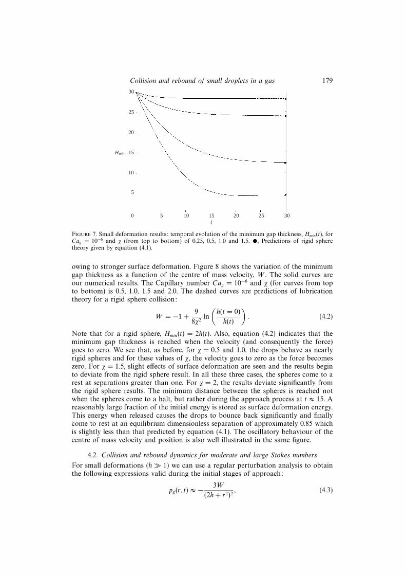
Collision and rebound of small droplets in a gas 179
25
20
15
10
5
0 5 10 30t
Hmin
30
15 20 25
Figure 7. Small deformation results: temporal evolution of the minimum gap thickness, Hmin(t), forCag = 10−6 and χ (from top to bottom) of 0.25, 0.5, 1.0 and 1.5. •, Predictions of rigid spheretheory given by equation (4.1).
owing to stronger surface deformation. Figure 8 shows the variation of the minimumgap thickness as a function of the centre of mass velocity, W . The solid curves areour numerical results. The Capillary number Cag = 10−6 and χ (for curves from topto bottom) is 0.5, 1.0, 1.5 and 2.0. The dashed curves are predictions of lubricationtheory for a rigid sphere collision:
W = −1 +9
8χ2ln
(h(t = 0)
h(t)
). (4.2)
Note that for a rigid sphere, Hmin(t) = 2h(t). Also, equation (4.2) indicates that theminimum gap thickness is reached when the velocity (and consequently the force)goes to zero. We see that, as before, for χ = 0.5 and 1.0, the drops behave as nearlyrigid spheres and for these values of χ, the velocity goes to zero as the force becomeszero. For χ = 1.5, slight effects of surface deformation are seen and the results beginto deviate from the rigid sphere result. In all these three cases, the spheres come to arest at separations greater than one. For χ = 2, the results deviate significantly fromthe rigid sphere results. The minimum distance between the spheres is reached notwhen the spheres come to a halt, but rather during the approach process at t ≈ 15. Areasonably large fraction of the initial energy is stored as surface deformation energy.This energy when released causes the drops to bounce back significantly and finallycome to rest at an equilibrium dimensionless separation of approximately 0.85 whichis slightly less than that predicted by equation (4.1). The oscillatory behaviour of thecentre of mass velocity and position is also well illustrated in the same figure.
4.2. Collision and rebound dynamics for moderate and large Stokes numbers
For small deformations (h� 1) we can use a regular perturbation analysis to obtainthe following expressions valid during the initial stages of approach:
pg(r, t) ≈ − 3W
(2h+ r2)2, (4.3)

180 A. Gopinath and D. L. Koch
101
–1.0 –0.9 0.1W
Hmin
100
–0.8 –0.7 –0.6 –0.5 –0.4 –0.3 –0.2 –0.1 0
(iv)
(ii)
(i)
(iii)
Figure 8. Small deformation results: variation of the minimum gap thickness as a function of thecentre of mass velocity, W . The capillary number Cag = 10−6 and χ (from top to bottom) is 0.5, 1.0,1.5 and 2.0. The solid curves are our numerical results and the dashed line corresponds to equation(4.2).
dW
dt≈ −9W
8χh, (4.4)
D(r, t) ≈ 3W
8χhln(2h+ r2) + f(t). (4.5)
Equation (4.2) indicates that collisions between drops with χ much greater thanapproximately (9 ln (h(t = 0))/8)1/2 will lead to a rebound. This is consistent with ourcalculations which indicate that for χ > 2, the drops deform strongly and a significantportion of the initial kinetic energy is stored as deformation energy.
In order to illustrate clearly the interesting aspects of the collision process, weexamine in detail two cases corresponding to χ = 3 (St = 2) and χ = 20 (St ≈ 88.8).For both of these, Cag = 10−6 and the initial conditions were, as before, h(t = 0) = 15and W (t = 0) = −1. Thus, χ is changed by changing Wed. The initial deformation wasset to zero and the temporal evolution of the pressure, deformation, gap thickness,centre of mass velocity and scaled force was analysed. An examination of thesevariables in conjunction provides a composite and complete picture of the approachand rebound process.
Consider first the collision dynamics for χ = 3 illustrated in figure 9. The drops
start with a minimum separation of 30(aCa1/2g ) and a relative velocity of 2U ′c directed
towards each other. As the drops approach, the gas in the intervening film resiststhe relative motion of the drops and generates a force that decelerates the centroids.The deformation during the initial stages of approach when h � 1 is negligible andhence the evolution of the gap, the force on the drops and the pressure profilesgenerated follow trends predicted by equations (4.3)–(4.5). The deformation andthe flow generated in the interior of the drops are small for 0 < t < 6, t beingthe scaled time. The decrease in the kinetic energy of the centroids is mostly dueto viscous dissipation in the gas film. Both the minimum gap thickness and the
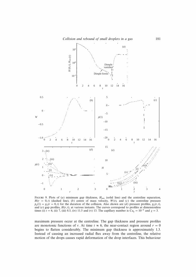
Collision and rebound of small droplets in a gas 181
(a)
10–1
100
101
Dimple forms
Dimplevanishes
0 2 4 6 8 10 12 14 16
H (
0,t)
, Hm
in (t
)
t
(b)
–0.5
0
0.5
0 2 4 6 8 10 12 14 16t
(d )
0 1 2 3r
(c)
0
5
0 2 4 6 8 10 12 14 16t
(e)
5
10
15
0 1 2 3 4r
–1.0
–5
–10
–15
–20
W p(1)
(iv)
(iii)
(ii)
(i)
(v)
3
2
1
0
–1
p(r)H
(iv) (iii)
(v)(i)
(ii)
Figure 9. Plots of (a) minimum gap thickness, Hmin (solid line) and the centreline separation,H(r = 0, t) (dashed line), (b) centre of mass velocity, W (t), and (c) the centreline pressurepg(1) = pg(r = 0, t) for the duration of the collision. Also shown are (d ) pressure profiles, pg(r, t),and (e) gap profiles, H(r, t), at various instants. The curves correspond to profiles at dimensionlesstimes (i) t = 6, (ii) 7, (iii) 8.5, (iv) 11.5 and (v) 13. The capillary number is Cag = 10−6 and χ = 3.
maximum pressure occur at the centreline. The gap thickness and pressure profilesare monotonic functions of r. At time t ≈ 6, the near-contact region around r = 0begins to flatten considerably. The minimum gap thickness is approximately 1.3.Instead of causing an increased radial flux away from the centreline, the relativemotion of the drops causes rapid deformation of the drop interfaces. This behaviour

182 A. Gopinath and D. L. Koch
is similar to the near contact motion of rigid spheres in a compressible gas where thegas tends to compress rather than flow out of the gap. The tendency of the drops todeform manifests itself in the decreased rate at which the minimum gap thickness Hmin
decreases. The rate of change of the force begins to decrease and both the velocityand the force profiles exhibit points of inflection. The pressure profiles begin to showa characteristic inner region where the gas pressure is O(1) and an outer region wherethe pressure is much less than 1. In the outer region, the pressure and deformationare given by the asymptotic forms (3.12) and (3.13). The decreasing gap separationcauses the pressure and deformation to become more localized, as is evident from thesteepening of the profiles in figures 9(d ) and 9(e) at t = 7. A dimple begins to form ata dimensionless time of t ≈ 8.2 and the minimum gap separation occurs at the rim ofthe dimple rather than at r = 0. At this point, the centreline pressure is approximately2 indicating that the pressure in the dimple area close to r = 0 is p′∞+2σ/a to leadingorder. The formation of the dimple causes a larger curvature at the rim comparedto the centreline and consequently, the gas film thins faster at the rim owing to therelatively larger pressure gradient. Thus, Hmin decreases faster than H(r = 0, t). Mostof the total force acting on the drops comes from the O(1) pressure in the dimpleregion. Note, however, that the centre of mass velocities have, by this time, reversedsign so that the centroids are actually moving away from each other even though thenear-contact regions are moving towards one another. An examination of the globaldrop deformation indicates that the drops become flattened at the end (around θ = π)and bulge out at the equator (around θ = 1
2π) at this time. The dimple meanwhile
increases in extent and reaches a maximum radial width of approximately 0.46 att ≈ 9.9. Note that although the film thickness remains approximately O(aCa
1/2g ), the
centroid to centroid distance becomes less than 2a by an amount O(aWe1/2d ). As the
dimple width begins to decrease, a larger fraction of the initial kinetic energy that isstored has been channelled back into the energy corresponding to the translationalmode, i.e. the centre of mass speed increases. The motion of the drops away fromeach other causes the interfaces beyond the dimple region to peel away from theplane of symmetry corresponding to z = 0. This motion occurs rather rapidly andleads to an adverse pressure gradient and a pressure that is less than the ambientpressure over the region beyond the dimple rim. Thus, at time t = 11.5, the pressureprofile is non-monotonic. It has two extrema, a maximum positive value at r = 0 anda minimum negative value just beyond the dimple. As the dimple shrinks, the forceacting on the drops decreases and the radial region over which pg > p∞ decreases.The centreline pressure is still of the order of 2. The radial flux out of the centrelineregion causes the separation at r = 0 to decrease with time and a tail to form. This tailthen pushes into the gap, resulting in a minimum film thickness with respect to time(primary minimum, H∗min) that occurs at t ≈ 12.2. Meanwhile, when t ≈ 12, the dimplevanishes and the minimum film thickness once again occurs at r = 0. The excess gaspressure at all points in the gap now rapidly becomes less than p′∞. This causes a fluxof gas into the gap which together with the relaxation of the surface deformationcauses the tail to retract back in a very short period of time. In fact, the tail formationand retraction occurs in a short time interval that is ∆t ≈ 0.8, compared to the time∆t ≈ 6 for which the dimple exists. By this time, the centre of mass velocity starts todecrease quite rapidly owing to the large negative force acting on each of the drops.As the drops move away from each other, the interplay and exchange of energybetween the deformation and the translational modes causes the centroids to executean oscillatory behaviour. In this case, we see that the residual energy remaining afterthe drops have rebounded back to beyond Hmin = 2 is rapidly dissipated. Eventually,
Collision and rebound of small droplets in a gas 183
the drops come to a rest at a dimensionless separation of approximately 3.5. Thus,this entire collision process may be considered one with an effective coefficient ofrestitution of zero since all the initial kinetic energy is dissipated and the drops donot rebound back to their initial separations. The net force acting on the drops slowlyincreases from zero at t = 0 and reaches a positive maximum at t ∼ 7.8, after whichit decreases. The force then becomes negative at t ∼ 10.2 decreases further due to thenegative pressure gradient in the thin gap, attains a negative minimum at t ∼ 12.3and then slowly increases to zero with pronounced oscillations as the drops come toa stop.
In order to investigate the dynamics at large Stokes numbers, we conductedtrajectory calculations for the case where χ = 20 and the capillary number was 10−6.The initial conditions were the same as for the χ = 3 case, i.e. h(t = 0) = 15 andW (t = 0) = −1, and the initial profiles were those for rigid spheres. Figure 10 showsthe temporal evolution of various quantities during the entire collision process. Inthis case, we terminated our calculations when the drops rebounded back to theirinitial separation. For small times, the dynamical behaviour was predicted well by thesmall deformation equations, namely (4.3)–(4.5). We expect that the initial approachbefore deformation is important, is faster than for the χ = 3 case and that thedrops approach to within an O(aCa
1/2g ) distance of each other in an O(aCa
1/2g U−1
c )time owing to negligible viscous dissipation in the gas film. In terms of scaled time,the initial approach occurs in a time of O(χ−1) for χ � 1. The force acting on thedrops during the initial stages is quite small and causes negligible deformation. Theincreasing centreline pressure eventually causes flattening of the surface around r = 0.A rather rapid increase in the centreline pressure occurs around t ≈ 0.8. The valueof h becomes zero at this point indicating that if the drops were rigid they wouldhave overlapped at this point. The centreline pressure begins to increase rapidly.At t ≈ 0.99, a dimple forms. The pressure at the centreline is slightly more than 2at this point but the profile is still evolving. Once the dimple forms, the centrelineseparation remains almost constant and changes very slowly. The separation at therim, on the other hand, decreases at a significantly faster rate owing to the largelocal pressure gradient in the gas and a smaller radius of curvature. The pressureand deformation profiles indicate that the force on the drop increases mainly due tothe lateral spreading of the dimple. The centreline pressure remains almost constant,but the motion of the drop squashes the near-contact surface thus leading to anincrease in dimple radius. The radial pressure profiles tend to a step shape with anear constant value in the dimple and with a sharp gradient at the rim. Beyond thedimple, the pressure drops extremely rapidly to the asymptotic value given by (3.13).Meanwhile, h reaches a minimum value of about −27.2 at t ≈ 2.92. The centroidsof the drops then begin to move away from each other. The minimum separation,however, continues to decrease and the dimple continues to spread attaining itsmaximum radial extent of about 3.03 at approximately t = 3.3. After this, the dimplewidth begins to decrease causing the force to decrease proportionately. The filmthickness at the rim reaches a minimum with respect to time at approximately t = 3.7and then begins to increase. The gap profile at this point (t ≈ 3.7) clearly shows thelarge radius of curvature in the interior of the dimple. This minimum, which we didnot observe in the χ = 3 case, we term the secondary minimum and denote by H∗∗min.The drops now begin to move apart slightly as the dimple relaxes by shrinking, theinterfaces beyond the rim gradually peeling away from each other. An interestingphenomenon then occurs. The film thickness at the centreline begins to decrease whilethe film thickness at the rim begins to increase. This causes the centreline pressure

184 A. Gopinath and D. L. Koch
(a)
10–1
100
101
Dimple formsDimple vanishes
0 2 3 5 6
H (
0,t)
, Hm
in (t
)
t
(b)
–0.4
0.8
0 2 5 6t
(d )
0 1 3 5r
(c)0
5
0 1 3 4 5 6t
(e)
1
2
3
0 1 2 3 4r
–20
–25
–30
W p(1)
(iv)
(iii)
(ii)
(i)
3
2
1
0
–1
–2
p(r) H
(iv)
(i)
(iii) (ii)
1 4
0.4
0
–0.8
1 73 4
–15
–10
–5
2
2 4
Figure 10. Plots of (a) minimum gap thickness, Hmin, (solid line) and the centreline separation,H(r = 0, t), (dashed line) (b) centre of mass velocity, W (t), and (c) the centreline pressurepg(1) = pg(r = 0, t) for the duration of the collision. Also shown are (d ) pressure profiles, pg(r, t),and (e) gap profiles, H(r, t), at various instants. The curves correspond to profiles at dimensionlesstimes (i) t = 1, (ii) t = 3.7 and (iii) t = 5. Curve (iv) in the pressure plot corresponds to t = 5.3 andin the gap thickness plot corresponds to t = 5.375. The capillary number is Cag = 10−6 and χ = 20.
to increase while the pressure beyond the rim begins to attain values less than theambient pressure (see profiles at t ≈ 5). The front separating regions of positive excessgas pressure from the negative region rapidly moves towards the centreline leading toa force that becomes negative – from this point on, viscous effects begin to dominate.The dimple completely relaxes by t ≈ 5.37; approximately the same time at which

Collision and rebound of small droplets in a gas 185
101
100
10–1
0 2 4 6 8 10 12 14 16 18 20t
(i)
(ii)(iii)
(iv)
Hmin
Figure 11. The temporal evolution of the minimum film thickness, Hmin(t), for various values ofthe scaled Stokes number χ and for a Capillary number of 10−6. The curves from right to leftcorrespond to (i) χ = 3, (ii) 4, (iii) 8 and (iv) 20, respectively. As χ increases, the dimple formationbecomes more pronounced and the secondary minimum that occurs during the dimple evolutionprocess becomes smaller than the primary minimum that occurs when the tail begins to retract.
the centreline excess pressure becomes negative. Curve (iv) in the pressure profileplot illustrates clearly the small region of positive pressure followed by the regionof negative pressure. The tail formation at r = 0 occurs because of the flux of gasout of the centreline region. The tail retraction occurs once the pressure in all of thelubrication region is less than ambient.
Figures 9 and 10 provide details of the collision process for two values of theStokes number. The dynamical behaviour is seen to be strikingly different and it isof interest to enquire into the transition from the O(1) to the St � 1 behaviour. Ofparticular relevance is the evolution of the minimum film thickness – the variation inthe primary and secondary minima as the Stokes number (or equivalently χ) changesand their relative magnitudes. Figure 11 is a plot of Hmin(t) for trajectory calculationswith Cag = 10−6. The profiles (from right to left) correspond to increasing Stokesnumbers. We see that for χ = 3, there is no evidence of a secondary minimum. As theStokes number increases, the dimple formation becomes more evident as indicatedby the formation of an inflection point at t ≈ 9 for χ = 4. For larger Stokes numbers(curves (iii) and (iv)), the dimple evolution process is very easily identified. The plotsindicate that the primary minimum (the sole minimum for small Stokes numbers)actually increases as the Stokes number increases. The secondary minimum, on theother hand, decreases as the Stokes number increases. Also, we see that the ratio ofthe time scale over which the tail retraction occurs to the time scale over which thedimple evolves becomes increasingly large as the Stokes number increases. Althoughnot shown in the figure, our numerical results also indicate that for sufficiently largevalues of χ, the secondary minimum corresponds to a smaller gap thickness than theprimary minimum.
Figure 12 shows the manner in which the dimple extent changes during the courseof the collision for four values of χ. The Capillary number is set constant at 10−6.
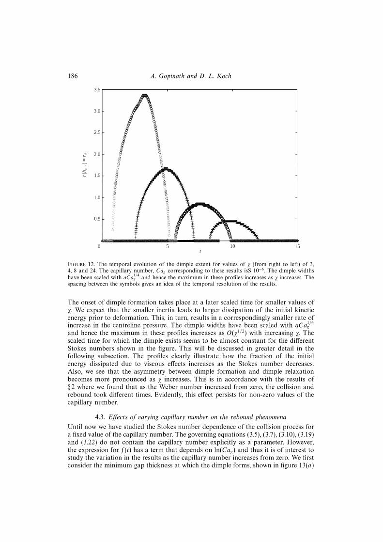
186 A. Gopinath and D. L. Koch
t
r(h m
in)
= r
d3.5
3.0
2.5
2.0
1.5
1.0
0.5
0 5 10 15
Figure 12. The temporal evolution of the dimple extent for values of χ (from right to left) of 3,4, 8 and 24. The capillary number, Cag corresponding to these results isS 10−6. The dimple widthshave been scaled with aCa
1/4g and hence the maximum in these profiles increases as χ increases. The
spacing between the symbols gives an idea of the temporal resolution of the results.
The onset of dimple formation takes place at a later scaled time for smaller values ofχ. We expect that the smaller inertia leads to larger dissipation of the initial kineticenergy prior to deformation. This, in turn, results in a correspondingly smaller rate ofincrease in the centreline pressure. The dimple widths have been scaled with aCa
1/4g
and hence the maximum in these profiles increases as O(χ1/2) with increasing χ. Thescaled time for which the dimple exists seems to be almost constant for the differentStokes numbers shown in the figure. This will be discussed in greater detail in thefollowing subsection. The profiles clearly illustrate how the fraction of the initialenergy dissipated due to viscous effects increases as the Stokes number decreases.Also, we see that the asymmetry between dimple formation and dimple relaxationbecomes more pronounced as χ increases. This is in accordance with the results of§ 2 where we found that as the Weber number increased from zero, the collision andrebound took different times. Evidently, this effect persists for non-zero values of thecapillary number.
4.3. Effects of varying capillary number on the rebound phenomena
Until now we have studied the Stokes number dependence of the collision process fora fixed value of the capillary number. The governing equations (3.5), (3.7), (3.10), (3.19)and (3.22) do not contain the capillary number explicitly as a parameter. However,the expression for f(t) has a term that depends on ln(Cag) and thus it is of interest tostudy the variation in the results as the capillary number increases from zero. We firstconsider the minimum gap thickness at which the dimple forms, shown in figure 13(a)

Collision and rebound of small droplets in a gas 187
(a)
0.7H
min
whe
n di
mpl
e fo
rms
(b)0.4
0.3
0
0.2
0.6
0.5
0.4
0 5 10 15 20 25
–0.2
–0.4
–0.6
–0.8
–1.00 5 10 15 20 25
Cen
tre
of m
ass
velo
city
whe
n di
mpl
e fo
rms
ø
Figure 13. Values of (a) the minimum film thickness, Hmin, and (b) the centre of mass velocity, W ,when the dimple forms. �, Cag = 10−8; �, 10−7; ◦, 10−6; 4, 10−5; ×, Cag = 10−4.
for capillary numbers spanning four decades from 10−8 to 10−4. For a fixed value of χ,as Cag increases, so does Hmin. For a fixed value of Cag as χ (or St increases) so doesHmin. Finally, as χ increases, the variation in Hmin as the capillary number changesbecomes slightly larger; our calculations seem to suggest, however, that these values

188 A. Gopinath and D. L. Koch
22
18
20
16
14
6
44 6 12 14 20 24
Tim
e to
reb
ound
bac
k to
init
ial s
epar
atio
n
ø
12
10
8
8 10 16 18 22
Figure 14. Plot of the total scaled time taken by the drops to rebound back to their initial
separation of 30(aCa1/2g ) starting from t = 0. �, Cag = 10−8; �, 10−7; ◦, 10−6; 4, 10−5.
tend to asymptote to constants as the Stokes number increase. Figure 13(b) showsthat, for small Stokes numbers (say χ = 3), the centre of mass velocity is positivewhen the dimple forms, i.e. the drops have already started the rebound process. Thus,the areas of near-contact are moving towards one another while the rear of the dropsare receding from each other. The value of the centre of mass velocity when thedimple forms is very weakly dependent on the capillary number – in fact, the collapsefor the wide range of Cag we consider is quite remarkable. As χ increases, the valueof W tends to −1, the deviation from this value is seen to be approximately O(χ−2)in accordance with the behaviour predicted by the equations for small deformation.Thus, for large Stokes numbers, the small deformation that occurs prior to the dimpleformation leads to negligible energy storage. Figure 14 shows the total time (scaledby aWe
1/2d U−1
c ) taken by the drops to rebound back to their initial separation of
30(aCa1/2g ) starting from t = 0. The calculations are for capillary numbers of 10−8,
10−7, 10−6 and 10−5. We note that the spread in values increases as the Stokesnumber increases. Also, at very small values of χ (say 4), collisions characterized bythe largest value of Cag (10−5) take the longest scaled time. However, as χ increases,this trend is reversed. At χ = 24, the smallest capillary number drops (Cag = 10−8)take the longest scaled time to complete the collision process. This result is consistentwith our idealized bounce calculations where we found that small Weber numbersresult in larger scaled bounce times. For small Stokes numbers, the effects of viscousdissipation play an important role and modify this trend.
Figure 15 shows the variation with changing χ in the values of the primary andsecondary minimum for two values of the capillary number (10−8 and 10−6). As χincreases from small values, the secondary minimum H∗∗min monotonically decreases
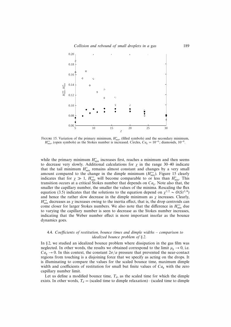
Collision and rebound of small droplets in a gas 189
0.20
0.18
0.16
0.14
0.08
0.06
0.12
0.10
H** m
in, H
* min
5 10 15 20 25 30ø
Figure 15. Variation of the primary minimum, H∗min, (filled symbols) and the secondary minimum,H∗∗min, (open symbols) as the Stokes number is increased. Circles, Cag = 10−6; diamonds, 10−8.
while the primary minimum H∗min increases first, reaches a minimum and then seemsto decrease very slowly. Additional calculations for χ in the range 30–40 indicatethat the tail minimum H∗min remains almost constant and changes by a very smallamount compared to the change in the dimple minimum (H∗∗min). Figure 15 clearlyindicates that for χ � 1, H∗∗min will become comparable to or less than H∗min. Thistransition occurs at a critical Stokes number that depends on Cag . Note also that, thesmaller the capillary number, the smaller the values of the minima. Rescaling the fluxequation (3.5) indicates that the solutions to the equation depend on χ1/2 ∼ O(St1/4)and hence the rather slow decrease in the dimple minimum as χ increases. Clearly,H∗∗min decreases as χ increases owing to the inertia effect, that is, the drop centroids cancome closer for larger Stokes numbers. We also note that the difference in H∗∗min dueto varying the capillary number is seen to decrease as the Stokes number increases,indicating that the Weber number effect is more important insofar as the bouncedynamics goes.
4.4. Coefficients of restitution, bounce times and dimple widths – comparison toidealized bounce problem of § 2.
In § 2, we studied an idealized bounce problem where dissipation in the gas film wasneglected. In other words, the results we obtained correspond to the limit µg → 0, i.e.Cag → 0. In this context, the constant 2σ/a pressure that prevented the near-contactregions from touching is a disjoining force that we specify as acting on the drops. Itis illuminating to compare the values for the scaled bounce time, maximum dimplewidth and coefficients of restitution for small but finite values of Cag with the zerocapillary number limit.
Let us define a modified bounce time, Td, as the scaled time for which the dimpleexists. In other words, Td = (scaled time to dimple relaxation) – (scaled time to dimple

190 A. Gopinath and D. L. Koch
5.5
2.5
Td
10–8 10–7 10–6 10–5 10–4 10–3 10–2
Wed
5.0
4.5
4.0
3.5
3.0
10–1 100
(i)
(ii)
(iii)
(iv)
Figure 16. The Weber number dependence of the modified bounce time defined as the scaled timefor which a dimple exists. -- -- --, Cag → 0 asymptote. �, Cag = 10−8; �, 10−7; ◦, 10−6; 4, 10−5.
formation). This allows us to correct for the dynamics of the initial trajectory, whichin the limit of St � 1, takes a very short O(aCa
1/2g U−1
c ) time compared to the muchgreater O(aWe
1/2d U−1
c ) time for the dimple to evolve. Furthermore, tail formation andretraction in the limit St� 1 takes place over a time period that is much smaller thanTd. Thus, Td is approximately the scaled time for which the centres of the two dropletsare closer than 2a for St� 1. Figure 16 shows the Weber number dependence of Tdfor Cag varying from 10−8 to 10−5. The limit of zero viscous dissipation is shown as adashed curve. For fixed Cag , the time Td increases from zero as χ (or equivalently, theWeber number), increases from zero. The comparative strengths of viscous dissipationand surface deformation dictate the time for which the dimple exists and control therate of drainage of the gas in the thin film. Consider the results for Cag = 10−8
denoted by diamonds. For Weber numbers smaller than approximately 10−6, thebounce times are smaller than those predicted by the zero capillary number theory.For small Stokes numbers, most of the initial kinetic energy is dissipated in thegas film; consequently, the energy available for surface deformation is reduced. Wecould try to correct for this effect by using the Stokes number based on the velocitywhen the dimple first forms. In addition, the dimple that eventually forms is not verypronounced and relaxes quickly. As χ increases, the drops deform rather than forcethe gas out of the gap and the gap separation remains almost constant over the timethe dimple evolves. Thus, for large Stokes number we expect Td to approach andfollow the dashed line. For a fixed Weber number, the smaller the Stokes number,the smaller the capillary number and so the dimple formation takes place at smallerseparations. Thus the smaller film thickness at the rim of the dimple leads to a largerresistance to change in the film thickness.
Figure 17 shows the maximum dimple width scaled with the undeformed dropradius a as a function of Wed for different values of Cag . The dashed line is thelimiting result corresponding to zero capillary number and provides an upper bound
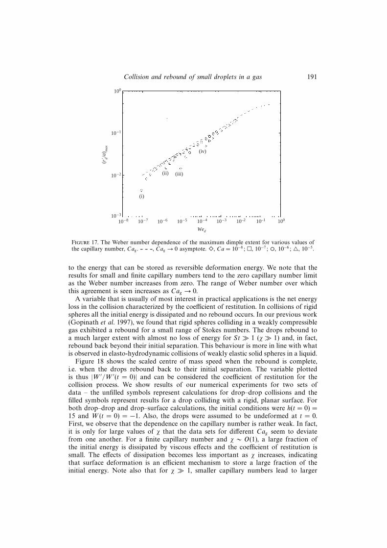
Collision and rebound of small droplets in a gas 191
(r! d/a
) max
10–8 10–7 10–6 10–5 10–4 10–3 10–2
Wed
10–1 100
(i)
(ii) (iii)
(iv)
10–3
10–2
10–1
100
Figure 17. The Weber number dependence of the maximum dimple extent for various values ofthe capillary number, Cag . -- -- --, Cag → 0 asymptote. �, Ca = 10−8; �, 10−7; ◦, 10−6; 4, 10−5.
to the energy that can be stored as reversible deformation energy. We note that theresults for small and finite capillary numbers tend to the zero capillary number limitas the Weber number increases from zero. The range of Weber number over whichthis agreement is seen increases as Cag → 0.
A variable that is usually of most interest in practical applications is the net energyloss in the collision characterized by the coefficient of restitution. In collisions of rigidspheres all the initial energy is dissipated and no rebound occurs. In our previous work(Gopinath et al. 1997), we found that rigid spheres colliding in a weakly compressiblegas exhibited a rebound for a small range of Stokes numbers. The drops rebound toa much larger extent with almost no loss of energy for St � 1 (χ � 1) and, in fact,rebound back beyond their initial separation. This behaviour is more in line with whatis observed in elasto-hydrodynamic collisions of weakly elastic solid spheres in a liquid.
Figure 18 shows the scaled centre of mass speed when the rebound is complete,i.e. when the drops rebound back to their initial separation. The variable plottedis thus |W ′/W ′(t = 0)| and can be considered the coefficient of restitution for thecollision process. We show results of our numerical experiments for two sets ofdata – the unfilled symbols represent calculations for drop–drop collisions and thefilled symbols represent results for a drop colliding with a rigid, planar surface. Forboth drop–drop and drop–surface calculations, the initial conditions were h(t = 0) =15 and W (t = 0) = −1. Also, the drops were assumed to be undeformed at t = 0.First, we observe that the dependence on the capillary number is rather weak. In fact,it is only for large values of χ that the data sets for different Cag seem to deviatefrom one another. For a finite capillary number and χ ∼ O(1), a large fraction ofthe initial energy is dissipated by viscous effects and the coefficient of restitution issmall. The effects of dissipation becomes less important as χ increases, indicatingthat surface deformation is an efficient mechanism to store a large fraction of theinitial energy. Note also that for χ � 1, smaller capillary numbers lead to larger

192 A. Gopinath and D. L. Koch
1.0
0.9
0.8
0.7
0.6
0.5
0.4
0.3
0.2
0.1
04 6 8 10 12 14 16 18 20 22 24
Coe
ffici
ent o
f re
stit
utio
n
ø
Figure 18. Final scaled rebound speeds, (effective coefficient of restitution) as a function ofχ = (Wed/Cag)
1/2 for drop–drop (unfilled symbols) and drop–rigid surface (filled symbols) collisions.�, Cag = 10−8; �, 10−7; ◦, 10−6; ., 10−5.
scaled rebound velocities, i.e. deformation effects dominate viscous effects. For all thecapillary numbers considered, rebound to the initial separation occurred so long asχ > 3. For smaller Stokes numbers, the drops came to a rest after executing dampedoscillations. The results for drops colliding with a rigid surface (filled symbols andsame notation) illustrate the increased dissipation that occurs owing to the no-slipcondition at the rigid surface. For drop–drop collision, this is replaced by a planeof symmetry with a no-stress condition and hence the dissipation is less. As theStokes number increases this difference in the boundary condition plays less of arole in determining the time scale of the bounce and the coefficient of restitution.Comparison of these results with the energy loss in the idealized collision process of§ 2 indicates that even in the limit Cag � 1, viscous dissipation cannot be neglectedfor St 6 O(1).
In the model we have developed and used, the near-contact deformed surfacesare assumed to have a large radius of curvature so that the lubrication, thin-filmequations apply. For the Stokes numbers considered in this paper, the lubricationassumption was indeed satisfied for the duration of the collision and rebound process.Our numerical results, however, do indicate that there is a possibility that this mightnot be valid, albeit for a very short period of time during the tail retraction periodwhen the curvature at r = 0 becomes very large. However, the total time thisphenomenon takes is negligible compared to the time over which the dimple evolvesand the energy dissipation during this time period is expected to be small. Sincethe collision is assumed to occur in an incompressible continuum gas, the grossdynamical quantities, namely, the force and velocity, will not change very much inthis time period.
Collision and rebound of small droplets in a gas 193
5. Concluding remarks
In this paper, we analysed the head-on collision and subsequent rebound of twoweakly deformable droplets in an incompressible continuum gas. Our results areapplicable when the Weber number based on the drop density Wed ≡ ρdU ′2
c a/σ � 1and the capillary number based on the gas viscosity Cag ≡ µgU
′c/σ � 1.
The Reynolds number based on drop properties Red ≡ aU ′cρd/µd �We1/2d .
In the first part of the paper, we analysed an idealized model of the bounce processvalid when viscous dissipation in the gas and in the drop can be ignored. We assumedthat the only effect of the gas was to supply a constant disjoining pressure to keepthe drop interfaces from touching. Such a description is valid provided that the rateof film drainage is so slow that in the time it takes for the drops to rebound, the filmthickness remains almost constant. For very small Weber numbers, we used singularperturbation methods to obtain a fully analytic description of the rebound process.Expressions for the rebound times and the extent over which surface flattening occurswere seen to match extremely well with exact simulations and available experimentaldata.
In the second part of the paper, we obtained the set of equations that provideda more complete picture of the collision process. The analysis took into account theflow in the drop and also in the thin gap separating the drops. These equations werethen solved numerically using a semi-implicit, direct, matrix inversion technique. Theeffects of viscous dissipation due to the flow of the gas out of the gap was studied indetail by varying the capillary number Cag . For large Stokes numbers and in the limitCag � 1, our calculations present the following picture of the approach and rebound
process. (i) During the initial approach when h′ � O(aCa1/2g ), the drops approach
each other with negligible deformation. The minimum gap thickness occurs at thecentreline. (ii) When the minimum gap thickness becomes O(aCa
1/2g ), the interfaces
in the inner region begin to flatten and deform significantly. A dimple then forms.The film thickness at the rim decreases faster than the gap thickness at the centreof the dimple. Meanwhile, the centre of mass velocity of the drop decreases withtime as a part of the initial kinetic energy is channelled into deformation energy,a part is stored in the pressure and velocity fields in the interior of the drop andthe remainder is dissipated due to gas viscosity. (iii) The centroids of the dropscome to rest momentarily and then reverse direction as the rebound process begins.Meanwhile, the minimum gap thickness that occurs at the dimple rim increases as thedimple reaches its maximum extent and begins to shrink. By this time, most of thedeformation energy is converted back to the kinetic energy associated with the centreof mass motion. (iv) The edges of the dimple peel away as the drops recede. Theminimum gap thickness occurs at the centreline and a tail forms. The rapid motionof the interfaces causes the pressure beyond the rim of the dimple to fall belowthe ambient value. The flux of gas out of the dimple that develops combined withsurface oscillations cause the thickness at the tip of the tail to decrease with time.The centreline separation reaches a minimum and then increases rapidly as the tailretracts. This retraction takes place over a time scale that is very small compared tothe time over which the dimple evolves and relaxes. (v) Once retraction is complete,the drops move away from each other. The velocity of the centre of mass of eachdrop increases, reaches a maximum and then decreases as viscous dissipation becomesimportant in the final stages of rebound.
Studies on elastohydrodynamic collisions of deformable solid spheres in an in-compressible liquid by Davis and co-workers (Davis et al. 1986; Serayssol & Davis
194 A. Gopinath and D. L. Koch
1986) showed that two dimensionless parameters influenced the dynamical characterof the collision process – an elasticity parameter that characterizes the tendency of thespheres to deform and the Stokes number. For small Stokes numbers, deformation aswell as the rebound height was seen to increase as the Stokes number increased. Also,the spheres underwent damped oscillations before finally coming to rest. For Stokesnumbers larger than a critical value dictated by the length scale at which deformationbecame important, the spheres rebounded very strongly. The minimum gap thicknessattained scaled by the characteristic length scale at which elastic deformation becameimportant tended to a constant as St → ∞. Most of the initial energy was storedas reversible elastic strain energy and was released during the rebound. In the timeperiod over which the rebound occurred, the gap thickness and the pressure in thegap remained nearly constant. Thus, although the equations governing the elastic de-formation of a solid body are very different from those governing the deformation ofa liquid–gas interface, we find that the dynamical behaviour is similar to what we ob-serve in collisions between drops. One main difference is that in a drop–drop collision,the whole drop surface deforms: the elastic spheres undergo localized deformation inthe region of close contact only.
We considered Stokes numbers of up to 200 in this analysis. Our results indicatethat both H∗∗min and H∗min vary extremely slowly with the Stokes number in the limitSt→ ∞. In fact, the results plotted in figure 15 indicate that H∗∗min scales as χa wherethe exponent a is about −0.5 when χ ∼ 20–30. The Stokes number dependence of theprimary minimum exhibits an even weaker dependence on the Stokes number.
The collision orientation we studied was axisymmetric about the line joining thecentroids of the drops. Since the gas film exerts only resisting forces and no inter-particle attractive forces are present, we do not expect to have unbounded growthof randomly induced surface oscillations. Based on the physics of the problem, it isreasonable to expect that the gas film will be stable to random perturbations – axialand transverse.
As mentioned before, collisions occurring in a continuum incompressible gas cannotend in contact due to the nature of the resisting lubrication force. Two physicallyrelevant mechanisms causing lubrication breakdown are compressibility of the gasand/or non-continuum effects. Compressibility effects will become important whenthe pressure drop along the gap becomes comparable to the outside ambient pressure.Consider the case of a collision between two identical rigid spheres moving towardseach other with equal speeds. Using the scaling of the pressure for incompressiblelubrication flow, p′ = O(µgU
′ca/h
′2), h′ being the minimum gap thickness, we canobtain an estimate of the relevant length, hc, at which compressibility effects becomeimportant. This is given by h′c ≡ (2µgU
′ca/p
′∞)1/2 where p′∞ is the ambient pressure.When the particle separation is comparable to or smaller than h′c the relative motionof the surfaces will cause the gas to compress rather than flow out (Gopinath et al.1997). Alternatively, when the gap between the particles becomes comparable to themean free path of the molecules, λo, the description of the gas as a continuum breaksdown and non-continuum effects have to be taken into account. For example, themean free path of air molecules is approximately 0.05µm and colliding drops wouldapproach to distances smaller than this value. The Navier–Stokes equation is theninadequate to represent the gas flow. We have to use the Boltzmann equation whichgoverns the evolution of the probability density of the gas. If the colliding drops haveinfinite surface tension (rigid spheres) lubrication breakdown will allow contact tooccur in finite time provided the drops have sufficient energy as shown in studies by(Sundararajakumar & Koch 1996; Gopinath et al. 1997). When drop deformation is

Collision and rebound of small droplets in a gas 195
taken into consideration we see clearly that the collision outcome is determined bythe relative importance of two competing effects – drop deformation which tends tostore energy and cause rebound, and lubrication breakdown mechanisms that allowfor contact to occur. In a subsequent publication, we will explore these in detail usinga formulation similar to that presented in this paper.
This work was supported by the US Environmental Protection Agency under grantnumber R827115. The authors would like to thank Dr Alexander Zinchenko for helpwith his thin film code and also for very useful and interesting discussions.
Appendix A. Scaling arguments used in the derivation of governingequations
A.1. Validation of basis function expansion
Examination of the linear operator Υo shows that if H = Hsol is a solution to theoperator equation ΥoH = ψ(η, t) then so is H =Hsol + γ1(t)η + γ2(t)F(− 1
2, 1, 1
2, η2),
γ1(t) and γ2(t) being appropriately chosen functions of time. Here F(− 12, 1, 1
2, η2) is a
generalized hypergeometric function and is logarithmically singular at η = ±1. Wenote now that since there are no sinks or sources of mass or momentum in the drop,the velocity potential φ has to be bounded at all points in the drop interior. Thekinematic interface condition combined with the Laplace equation for the velocitypotential suggests that the rate at which deformation occurs should also be boundedat points on the drop surface. At the point diametrically opposite to the point ofclose contact, i.e. at η = −1, the drop deformation should be small and bounded.Since we have specified that the interface be flat over the region θ = 0 to θ = α,the matching is actually carried out at the edge of the dimple, namely, at η = cos αwhere F(− 1
2, 1, 1
2, η2) is bounded. In addition, at the start of the collision process,
i.e. at t = 0, the dimple extent is zero and so the drops are exactly spherical correctto O(We
1/2d ). These conditions, together with the criterion that the velocity potential
should be bounded, allow us to writeH as a linear superposition of a set of completeand bounded basis functions. The regular parts of the homogeneous solutions canthen be rewritten in terms of these basis functions too.
A.2. Outer trajectory scaling
The outer trajectory calculations are started when the drops are separated by adistance equal to O(a) and are undeformed. At inter-drop distances of O(a), the gasflow around the drops is governed by the Stokes equations provided St < O(ρd/ρg).As the drops converge, the dynamic pressure that is created in the gas scales roughlyas O(µgU
′c/a). For St � 1, the centre of mass speeds do not change much in the
time it takes for the separation to reduce to a value that marks the beginning ofthe lubrication regime. The centre of mass velocity of the drops relaxes on a viscoustimescale τv ∼ 2ρda
2(9µg)−1. The characteristic magnitude of the deformation induced
velocities is uf � U ′c and this velocity evolves over a time scale τc ∼ O(a/U ′c) � τv .Because the governing equations for Stokes flow are quasi-steady and linear, thepressure and the velocity fields set up in the gas at any given time are completelydetermined by instantaneous velocities and position of the interfaces. To leadingorder, the deformation of the surface is small compared to the radius a and may beneglected. Similarly, the velocity of each drop–gas interface is approximately equal tothe velocity of the centroid of the corresponding drop. The deformation in the outertrajectory becomes important only for moderately small or O(1) values of Ca
1/2g ;
196 A. Gopinath and D. L. Koch
in these cases, we can neglect any induced tangential velocity of the surfaces. Thepressure and velocity fields in the gas can be obtained by solving for the flow aroundtwo rigid spheres moving towards each other with specified velocities. These velocitiesare in turn determined by the overall hydrodynamic force acting on the drops.
We write the drop velocity as u′d(r′, t′) = u′cm(t′) + u′f(r′, t′) where u′cm(t′) ∼ O(U ′c)and u′f � u′cm(t′). The part u′f(r′, t′) is the deformation induced velocity and is smallcompared to the centre of mass velocity. Then,
ρd∂u′cm∂t′∼ O
(ρdU ′cτv
), ρd
∂u′f∂t′∼ O
(ρdU ′cτv
τv
τc
uf
U ′c
), ρdu
′cm · ∇′u′f ∼ O
(ρdU ′cτv
τv
τc
uf
U ′c
)
ρdu′f · ∇′u′f ∼ O
(ρdU ′cτv
τv
τc
(uf
U ′c
)2), µd∆
′u′f ∼ O(ρdU ′cτv
τv
τc
uf
U ′cRe−1
d
).
When Red � 1, the viscous term can be neglected in comparison to other terms. TheStokes number, St ∼ τc/τv > 1. For Red � 1 and St � 1, the flow induced in thedrop due to deformation and surface stress is less than the centre of mass speed,namely, uf/U
′c � 1, the nonlinear quadratic inertial term u′f · ∇′u′f may be neglected.
For Stokes numbers 1� St� Ca−1g , the capillary pressure balances the external gas
pressure O(µgU′c/a); thus, the deformation is O(aCag) and uf ∼ O(U ′cCag)� U ′c. For
the dynamic drop pressure to be of the same order as this gas pressure, we requirethat p′d = p′o +2σ/a+O(aρdU
′cτ−1v ) and the governing equation then attains the simple
form:
ρd∂u′cm∂t′
+ ∇′p′d = 0.
This equation applies even for moderately large or O(1) drop Reynolds numbers.When St ∼ O(1) and for moderately small capillary numbers say, Cag ∼ O(0.1), weexpect that the induced flow occurring inside the drop should be included in ouranalysis. Scaling time with tc and the dynamic pressure with µgU
′c/a we obtain:
Wed
Cag
(ducmdt
)+Wed
[∂uf∂t
+ ucm · ∇uf]
= −∇Pd.
Here, we have assumed (subject to verification) that uf = U ′cCag . Note that the netforce on each drop scales like O(µgU
′ca). The first term on the left-hand side is actually
O(1) whereas the other terms on the left-hand side are O(Wed) < 1. Thus, as longas St > O(1) and Wed < 1, the main contribution to the pressure gradient in thedrop comes from the net force acting on the drop and we need not consider the flowinside the drop to calculate the deformation to leading order – just the net force actingon the drop due to the gas outside will suffice. The correction to the leading-orderO(1) term becomes increasingly important and uf becomes of the order of U ′c. As acheck of consistency, we note that for Wed 6 1, the deformation is O(aCag) and thecharacteristic velocity is indeed O(U ′cCag) as is assumed in the scaling.
A.3. Alternative derivation of outer equations
In deriving equation (3.23) we have neglected higher-order terms that vanish asCag → 0. An additional condition that results is that r2(Cag/Wed)
1/2 � 1 +ln[r2(Cag/Wed)
1/2]/2. A physical interpretation of this criterion is that the defor-mation at the outer edge of the lubrication layer and in the matching region, shouldbe small compared to the undeformed radius. We may also derive equation (3.23) in

Collision and rebound of small droplets in a gas 197
a manner comparable to the analysis in § 2. We consider a mean constant pressure ofvalue equal to 4
3ρdU
2cWe
−1/2d (sin α)−2dW/dt acting over a flat region of radial extent
(a sin α). Using this step function form for the pressure profile in (3.22), we can writedown the rate at which the velocity in the drop changes. In the limit α → 0, wefind, as expected, that only the net force acting in the inner region determines thedeformation in the outer region and details of the deformation in the inner regionare not important.
Appendix B. Numerical methodologyB.1. Numerical scheme and discretization
The first order, implicit (backward) Euler scheme for the time derivative and centraldifferences for the radial derivative were used to solve the equations. The implicittime-stepping scheme renders the numerical computation stable whereas the centraldifferencing adopted allows for second-order accuracy in space.
First, we discretize the equations at points ri; i = 1, 2, . . . , N + 1 where rN+1 is thelast grid point selected such that the asymptotic form for the deformation is satisfied.Then, given the gap profile Hn, pressure png , force Fn, velocity Wn and hn at the nthtime level, the equation for the flux, namely (3.5), was made semi-implicit and linearin Hn+1 and pn+1
g thus:
1
r
∂
∂r
[r(H3)n
(∂pg
∂r
)n+1]
= 24Qn+1 = 241
χ
(Yn+1 −Yn
dt
), (B 1)
where
Yn+1 = hn+1 + χDn+1 = hn+1 +
(Wed
Cag
)1/2
Dn+1, (B 2)
Qn+1 = Wn+1 +
(dD
dt
)n+1
=1
χ
(dYdt
)n+1
, (B 3)
so that
Hn+1 = 2Yn+1 + r2. (B 4)
The time rates of change of h and W are given by:(dh
dt
)n+1
=hn+1 − hn
dt= χWn+1 (B 5)
and (dW
dt
)n+1
=3
2χ
∫ r∞
0
pn+1g r dr =
Wn+1 −Wn
dt. (B 6)
We have set the pressure at infinity, p∞, to be zero for convenience and we alsotake the limit r∞ → ∞ when evaluating the force. The Young–Laplace equation isevaluated thus:
1
r
∂
∂r
(r∂Y∂r
)n+1
= −pn+1g . (B 7)
This procedure parallels that used in the paper by Rother et al. (1997) and is similarto the linearization process advocated by Lees (1966). In addition, the equations for

198 A. Gopinath and D. L. Koch
Lk and Bk are differenced as (for k > 2)(dLk
dt
)n+1
=Ln+1
k −Lnk
dt= kBn+1
k , (B 8)
(dBkdt
)n+1
=Bn+1k − Bnk
dt= −(k2 + k − 2)Ln+1
k − 2k + 1
3
(dW
dt
)n+1
. (B 9)
The boundary conditions on the variables pg and Y are given by:
pn+1g (rN+1) =
−3
r4N+1
Qn+1(rN+1) (B 10)
and
Yn+1(rN+1) = hn+1 + χDn+1(rN+1), (B 11)
where
Dn+1(rN+1) = −2
3
(dW
dt
)n+1
ln(rN+1) + fn+1(t), (B 12)
and the constant fn+1 is evaluated using (3.27) and (3.28). Now integrating (B 1) twiceover r, using the symmetry condition at r = 0 and equation (B 10), changing the orderof integration and finally discretizing using the trapezoidal rule we obtain a matrixequation relating pn+1
g to Qn+1 of the form pn+1g = E ·Qn+1. Similarly, integrating (B 7)
twice over r, imposing the symmetry condition at the origin and using the matrix formfor the pressure we obtain an equation for Y n+1 in terms of Yn+1(r = 0, t) and pn+1
g .Here, the elements of pn+1
g , Qn+1 and Y n+1 are values of pg , Q and Y at grid pointsri, i = 1, 2, . . . , N + 1 where the last grid point is rN+1. Using these matrix equations,we finally obtain a matrix equation for Qn+1:
S ·Qn+1 = −Y n +Yn+1(r = 0, t)1, (B 13)
where S is obtained by substituting the matrix form of (B 1) into the matrix form of(B 7). Note that Yn+1(r = 0, t) is as yet unknown. The solution to (B 13) is written asQn+1 = Qn+1
1 +Yn+1(r = 0, t)Qn+12 where
S ·Qn+11 = −Y n, S ·Qn+1
2 = 1. (B 14)
These equations may then be used to obtain an algebraic equation for the unknowngap width Yn+1(r = 0, t). This, when known, can be substituted back to find Qn+1 andhence Yn+1, pn+1
g ,Wn+1, Fn+1, hn+1 and Hn+1. It should be pointed out that the directsemi-implicit scheme has some similarities to the three-level scheme proposed by Lees(1966) to solve quasi-linear parabolic equations. The algorithm proposed by Rotheret al. achieves linearization of the governing equations in a similar manner; however,because backward (implicit) Euler differencing is used for the time derivatives andcentral differences for the space derivatives, the complicated boundary condition onthe gap thickness at large r can be implemented easily.
The accuracy of the numerical method was checked by comparing the solutionsobtained at different values of ∆t and ∆r. Varying ∆t allows us to test the temporalaccuracy of the solutions while varying ∆r allows us to probe the effect of gridresolution. In our calculations, the last grid point was chosen such that the asymptoticexpression for the deformation was readily satisfied. We used a mesh with a fixednumber of grid points but varying grid size in order to make sure that deformationand pressure gradients were resolved accurately. The mesh contracted as the drops
Collision and rebound of small droplets in a gas 199
came closer to one another and expanded as the drops receded from each other. Themesh size was made constant as soon as the dimple formed and remained constantuntil the dimple vanished. Most calculations were carried out with 251 grid points.Calculations with 151–601 grid points showed nearly identical results with variationsin rebound times and minimum gap thickness of less than 2%. The cutoff value forthe last grid point was calculated as rsc[Hmin(t)/2]1/2 where rsc is a scaling coefficient.Most calculations used rsc = 20 so that the last point was sufficiently larger than themaximum dimple width. Values of rsc in the range 10–30 resulted in the same valuesof all dynamical quantities. We note that the pressure decays very rapidly beyond thedimple and hence the cutoff radius does not have to be much larger than the dimpleextent. Typical values of the time increment ∆t used ranged from 10−1/5–10−2/5.In all cases, we made sure that converged results were obtained. A small time stepwas used in the tail formation and retraction step so that the fast dynamics of tailretraction could be adequately captured. Finally, the cutoff number for the outermodes we used were Nc = 3–4 for χ ∼ O(1) and Nc = 5–7 for χ� 1.
B.2. Validation of numerical code: application to collision of a deformable drop with arigid wall owing to the action of a constant force
In order to validate the numerical code and test its accuracy and convergenceproperties, we analysed the buoyancy driven collision of a deformable drop with arigid flat wall in the presence of a gas. This corresponds to zero Stokes number (nodrop inertia) and a constant body force. Numerical results for the film thickness andpressure profiles obtained from our code were compared with those obtained by acompletely different method by Yiantsios & Davis (1990). The equations we solve (indimensionless form) are:
1
r∗∂
∂r∗
[r∗H∗3
(∂p∗
∂r∗
)]=∂Y ∗
∂t∗(B 15)
1
r∗∂
∂r∗
(r∗∂Y ∗
∂r∗
)= −p∗ (B 16)
and2
3=
∫ ∞0
p∗r∗dr∗, (B 17)
with
H∗ = Y ∗ + 13r∗2. (B 18)
Here, p∗ is the scaled gas pressure and H∗ is the scaled gap thickness. Flow of theliquid inside the drop may be neglected in this case. In this case too, we find that forlarge r∗, the deformation diverges as ln r∗ and the O(1) constant required to determinethe deformation far from the lubrication region is obtained from equation (B 17).
In accordance with the initial conditions used by Yiantsios & Davis, we started ourcalculations with Y ∗ = 20 and traced the trajectory of the drop over several decadesin time. We used a contracting mesh with 200 grid points and a dimensionless step sizedt∗ = 10−1. The results using a step size dt∗ = 10−2 and 400 grid points do not changethe solution values significantly. Our results for the deformation and pressure profilesat various instants in time compared extremely well with the graphs in Yiantsios &Davis. Figure 19(a) illustrates the validity and accuracy of our calculations comparedto Yiantsios & Davis. The two solid lines show the variation of the scaled centrelinegap separation, H∗(r∗ = 0, t∗), and the minimum gap thickness, H∗min(t∗), respectively.

200 A. Gopinath and D. L. KochH
* (0,
t*),
H* m
in(t
* )
t*
102
101
100
10–1
10–2
10–3
10–2 10–1 100 101 102 103
(a)
10–1 100 101
(b)(iii)(ii)
(i)
1.6
1.4
1.2
1.0
0.8
0.6
0.4
0.2
0
r*
p* (
r*)
Figure 19. (a) Temporal evolution of the minimum gap width and the centreline gap width for zeroinertia drops colliding due to the action of a constant force (b) Profiles of the pressure in the gasfilm at various instants in time illustrating dimple evolution. Note the steepening of the pressureprofile leading to a sharper pressure gradient at the rim as time increases.
The line with short dashes is a regular perturbation, asymptotic solution valid for smalldeformations (small times) and the line with long dashes is the long-time asymptoticsolution for the minimum gap thickness, H∗min, representing the quasi-steady approachof the drop interfaces. This long-time asymptote is given by,
H∗min(t∗) ∼ 0.4897 . . . ( 3
16)1/2t∗−1/2.
The solid circles and the crosses are numerical results obtained by Yiantsios &Davis using an iterative nonlinear solver. These values were obtained from a visualexamination of the graphs in their paper. Note that at short times, a dimple is notformed and so the minimum gap thickness occurs at r∗ = 0. However, at t∗ ≈ 10.0,a dimple forms and the minimum gap width occurs not at r∗ = 0, but at the rim ofthe dimple. Figure 19(b) shows the pressure profiles in the gap when H∗min = 1.0, 0.10and 0.05. These pressure profiles match those in Yiantsios & Davis. As the dropscome closer, the dimple radius keeps increasing with time and the pressure in thedimple also increases. The pressure gradient at the rim of the dimple becomes largerat the same time. For very large times, the nearly constant pressure in the dimple andthe radial extent of the dimple region may be obtained by balancing the lubricationforce with the external driving force causing the collision. Calculations indicate thatfor the initial conditions we adopted, the dimple reaches slightly more than 93% ofits maximum extent by a dimensionless time t∗ ≈ 75, a value that agrees with thatreported by Yiantsios & Davis. In fact, all our numerical results for the pressure anddeformation profiles and the temporal evolution of the dimple radius also match verywell with the results of Yiantsios & Davis.
REFERENCES
Ashgriz, N. & Poo, J. Y. 1990 Coalescence and separation in binary collision of liquid drops.J. Fluid Mech. 221, 183.
Barnocky, G. & Davis, R. H. 1989 The influence of pressure-dependent density and viscosity onthe elastohydrodynamic collision and rebound of two spheres. J. Fluid Mech. 209, 501.
Bradley, S. G. & Stow, C. D. 1978 Collision between liquid drops. Phil. Trans. R. Soc. Lond. A287, 635.
Collision and rebound of small droplets in a gas 201
Brazier-Smith, P. R., Jennings, S. G. & Latham, J. 1972 The interaction of falling water drops:coalescence. Proc. R. Soc. Lond. A 326, 393.
Davis, R. H., Schonberg, J. A. & Rallison, J. M. 1989 The lubrication force between two viscousdrops. Phys. Fluids A 1, 77.
Davis, R. H., Serayssol, J.-M. & Hinch, E. J. 1986 The elastohydrodynamic collision of twospheres. J. Fluid Mech. 163, 479.
Foote, G. B. 1975 The water drop rebound problem: dynamics of collision. J. Atmos. Sci. 32, 390.
Friedlander, S. K. 1977 Smoke, Dust and Haze: Fundamentals of Aerosol behavior. Wiley.
Fuchs, N. A. 1964 The Mechanics of Aerosols. Pergamon.
Gopinath, A., Chen, S. B. & Koch, D. L. 1997 Lubrication flows between spherical particlescolliding in a compressible non-continuum gas. J. Fluid Mech. 344, 245.
Hidy, G. M. & Brock, J. R. 1970 The Dynamics of Aerocolloidal Systems. Pergamon.
Jayaratne, O. W. & Mason, B. J. 1964 The coalescence and bouncing of drops at an air/waterinterface. Proc. R. Soc. Lond. A 280, 545.
Jiang, Y. J., Umemura, A. & Law, C. K. 1992 An experimental investigation on the collisionbehaviour of hydrocarbon droplets. J. Fluid Mech. 234, 171.
Karl, A. & Frohn, A. 2000 Experimental investigation of the interaction process between dropletsand hot walls. Phys. Fluids 12, 785.
Lees, M. 1966 A linear three-level difference scheme for quasilinear parabolic equations. Math.Comput. 20, 516.
Mason, B. J. 1971 The Physics of Clouds. Oxford.
Murad, S. & Law, C. K. 1999 Molecular simulation of droplet collision in the presence of ambientgas Mol. Phys. 96, 81.
Nobari, M. R., Jan, Y.-J. & Tryggvason, G. 1996 Head-on collision of drops – a numericalinvestigation. Phys. Fluids 8, 29.
Ochs, H. T. & Beard, K. V. 1985 Effects of coalescence efficiencies on the formation of precipitation.J. Atmos. Sci. 42, 1451.
Ochs, H. T., Czys, R. R. & Beard, K. V. 1980 Laboratory measurements of coalescence efficienciesfor small precipitation drops. J. Atmos. Sci. 3, 225.
Park, R. W. 1970 Behaviour of water drops colliding in humid nitrogen. PhD thesis, Departmentof Chemical Engineering, The University of Wisconsin.
Qian, J. & Law, C. K. 1994 Effects of ambient gas pressure on droplet collision. AIAA PaperAIAA-94-0681.
Rother, M. A., Zinchenko, A. Z. & Davis, R. H. 1997 Buoyancy-driven coalescence of slightlydeformable drops. J. Fluid Mech. 346, 117.
Serayssol, J.-M. & Davis, R. H. 1986 The influence of surface interactions on the elastohydro-dynamic collision of two spheres. J. Coll. Interface Sci. 114, 54.
Spengler, J. D. & Gokhale, N. R. 1973 Drop impactions. J. Appl. Meteorol. 12, 316.
Sundararajakumar, R. R. & Koch, D. L. 1996 Non–continuum flows between particles collidingin a gas. J. Fluid Mech. 313, 283.
Tsao, H.-K. & Koch, D. L. 1994 Collisions of slightly deformable, high Reynolds number bubbleswith short-range forces. Phys. Fluids 6, 2591.
Wachters, L. H. J. & Westerling, N. A. J. 1966 The heat transfer from a hot wall to impingingwater drops in the spheroidal state. Chem. Engng Sci. 21, 1047.
Yao, S.-C. & Cai, K. Y. 1988 The dynamics and Leidenfrost temperature of drops impacting on ahot surface at small angles. Exp. Therm. Fluid Sci. 1, 363.
Yiantsios, S. G. & Davis, R. H. 1990 On the bouyancy-driven motion of a drop towards a rigidsurface or a deformable surface. J. Fluid Mech. 217, 547.
Copyright © 2022 FDOKUMEN