Numerical study of the coupled heat and mass transfer in membrane distillation
8
Desalination 152 (2002) 245–252 0011-9164/02/$– See front matter © 2002 Elsevier Science B.V. All rights reserved Presented at the EuroMed 2002 conference on Desalination Strategies in South Mediterranean Countries: Cooperation between Mediterranean Countries of Europe and the Southern Rim of the Mediterranean. Sponsored by the European Desalination Society and Alexandria University Desalination Studies and Technology Center, Sharm El Sheikh, Egypt, May 4–6, 2002. *Corresponding author. Numerical study of the coupled heat and mass transfer in membrane distillation S. Bouguecha a , R. Chouikh b , M. Dhahbi a * a INRST, BP 95 Hammam-lif 2050, Tunisia Fax +216 (71) 430-934; emails: [email protected], [email protected] b IPEIN, Campus Universitaire Merazka Nabeul, Tunisia Fax +216 (71) 430-934; email: [email protected] Received 30 March 2002; accepted 10 April 2002 Abstract In order to deepen the understanding of the permeate characteristics of membrane distillation considering heat and mass transfers and concentration polarisation, a fully predictive mathematical model was developed. The first part that is devoted to the natural heat and mass transfer in the rectangular cavity, states the problem in Cartesian coordinates system, involves the use of a control-volume method and solves the full vorticity transport equation together with the stream function, mass and energy equations. The temperature fields and streamlines are plotted for various geometrical conditions to show some of the flow field characteristics. The second part was set up to simulate the phenomenon present in the membrane distillation process. The mass transfer was described with combined Knudsen and Maxwell–Stefan equations and coupled to the simultaneous heat transfer. The effect of parameters such as thickness of cavity, temperature and feed flow rate were investigated. The results were compared with the available data and the agreement is satisfactory. Keywords: Membrane distillation; Air gap membrane distillation method; Heat and mass transfer; Modelling
Transcript of Numerical study of the coupled heat and mass transfer in membrane distillation
Desalination 152 (2002) 245–252
0011-9164/02/$– See front matter © 2002 Elsevier Science B.V. All rights reserved
Presented at the EuroMed 2002 conference on Desalination Strategies in South Mediterranean Countries:Cooperation between Mediterranean Countries of Europe and the Southern Rim of the Mediterranean.Sponsored by the European Desalination Society and Alexandria University Desalination Studies and TechnologyCenter, Sharm El Sheikh, Egypt, May 4–6, 2002.
*Corresponding author.
Numerical study of the coupled heat and mass transfer inmembrane distillation
S. Bouguechaa, R. Chouikhb, M. Dhahbia*aINRST, BP 95 Hammam-lif 2050, Tunisia
Fax +216 (71) 430-934; emails: [email protected], [email protected], Campus Universitaire Merazka Nabeul, Tunisia
Fax +216 (71) 430-934; email: [email protected]
Received 30 March 2002; accepted 10 April 2002
Abstract
In order to deepen the understanding of the permeate characteristics of membrane distillation considering heatand mass transfers and concentration polarisation, a fully predictive mathematical model was developed. The firstpart that is devoted to the natural heat and mass transfer in the rectangular cavity, states the problem in Cartesiancoordinates system, involves the use of a control-volume method and solves the full vorticity transport equationtogether with the stream function, mass and energy equations. The temperature fields and streamlines are plotted forvarious geometrical conditions to show some of the flow field characteristics. The second part was set up to simulatethe phenomenon present in the membrane distillation process. The mass transfer was described with combinedKnudsen and Maxwell–Stefan equations and coupled to the simultaneous heat transfer. The effect of parameterssuch as thickness of cavity, temperature and feed flow rate were investigated. The results were compared with theavailable data and the agreement is satisfactory.
Keywords: Membrane distillation; Air gap membrane distillation method; Heat and mass transfer; Modelling
246 S. Bouguecha et al. / Desalination 152 (2002) 245–252
1. Introduction
Membrane distillation is a separation processthat involves transport of water vapour throughporous hydrophobic membranes. A variety ofmethods may be employed to impose this vapourpressure difference. In the present work, the airgap membrane distillation method (AGMD) isconsidered. The principal advantage of AGMDagainst other configurations of membrane dis-tillation arises from the possibility to condensingthe permeate vapours on a cold surface rather thandirectly in a cold liquid. In this configuration, themass transfer steps involve movement within theliquid feed toward the membrane surface, evapo-ration at the membrane interface and transport ofthe vapour through the membrane pores and airgap prior to condensation. So, the separationmechanism of membrane distillation and its per-formance is based on vapour–liquid equilibrium.The driving force of the process is supplied bythe vapour pressure difference caused by the existingtemperature difference between the liquid–vapourinterfaces. The benefits of membrane distillationover conventional distillation processes are foundin the lower operating temperatures and pressuresthat reduce the equipment surface and costs, thecompact modules and the possibility of overcomingcorrosion problems by using plastic equipment.The lower operating temperatures can use availableenergy sources such as solar and geothermal energiesor waste energy in industrial processes. That iswhy transmembrane evaporation applied to thedesalination of seawater is a very promising tech-nology to reduce the production costs of water fromfresh water sources [1] (lakes, solar pond, etc.).However, at this moment little knowledge isavailable about the optimal design of such atransmembrane evaporation process. In fact, thecoupling and non-linearity of the equations, theinteraction between the flow and the thermal plumein the cavity and the complicated geometriesinvolved have forced experimental solutions. So,the evident lack of data for thermal and dynamicinteractions in natural convection within the
cavity prompted the present study. This workpresents a model for preliminary design cal-culations that is used to evaluate the effect of themain design parameters in the transmembraneevaporation module performance for water desali-nation.
2. Principle of membrane distillation
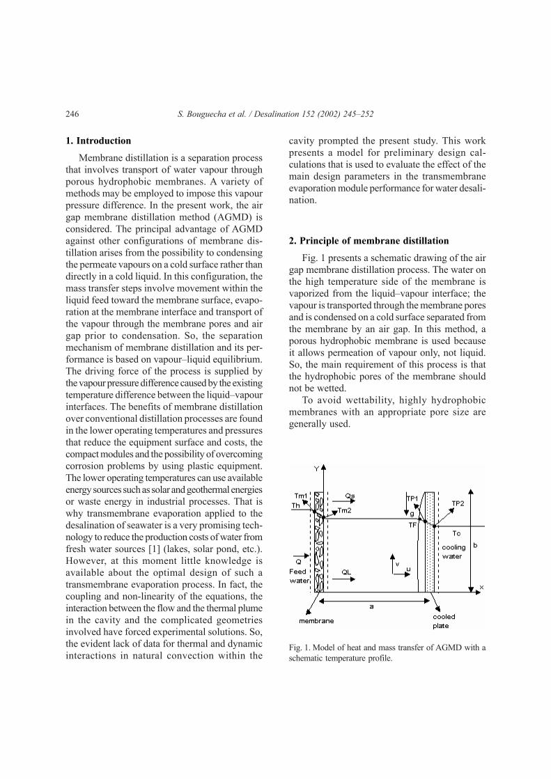
Fig. 1 presents a schematic drawing of the airgap membrane distillation process. The water onthe high temperature side of the membrane isvaporized from the liquid–vapour interface; thevapour is transported through the membrane poresand is condensed on a cold surface separated fromthe membrane by an air gap. In this method, aporous hydrophobic membrane is used becauseit allows permeation of vapour only, not liquid.So, the main requirement of this process is thatthe hydrophobic pores of the membrane shouldnot be wetted.
To avoid wettability, highly hydrophobicmembranes with an appropriate pore size aregenerally used.
Fig. 1. Model of heat and mass transfer of AGMD with aschematic temperature profile.

S. Bouguecha et al. / Desalination 152 (2002) 245–252 247
3. Theoretical study
3.1. Modelling of the flow
Using the stream function–vorticity approachand assuming constant properties except for thedensity in the body force term, the coupled elliptictransport equations for ψ, ω, ξ and T written inCartesian coordinates, in dimensionless form andfor steady state 2-dim. laminar natural convection,are as follows:• Continuity equation:
**
*
*
*2
2
2
2
−=∂∂
+∂∂
yx (1)
• Vorticity equation:
∂∂+
∂∂+
∂∂+
∂∂=
∂∂+
∂∂
2
2
2
2
*
*
*
*Pr
*
*PrRa
*
*PrRa
*
**
*
**
yxx
x
T
yV
xU
M
T
(2)
• Energy equation:
∂∂+
∂∂=
∂∂+
∂∂
2
2
2
2
*
*
*
*
*
**
*
**
y
T
x
T
y
TV
x
TU (3)
• Mass equation:
∂∂+
∂∂=
∂∂+
∂∂
2
2
2
2
*
*
*
*
Sc
Pr
*
**
*
**
yxyV
xU (4)
The boundary conditions are as follows:• On the membrane:
T* = ζ* = 1, U* = V* = ψ* = 0 (5)
• On the cooling plate:
T* = ζ* = U* = V* = ψ* = 0 (6)
• On the adiabatic walls:
0****
*
*
* ====∂∂=
∂∂
VUyy
T(7)
We derive the boundary condition for ω* byexpanding the stream function near the wall as aTaylor series and then using the continuity andthe no-slip condition.
∆
−=
2*
**2*
n
W
(8)
n* denotes the normal direction from the wall.ψW* is the stream function value at the wall andψ* is the value at a short distance ∆n* into thefluid.
3.2. Mass and heat transfer
In membrane distillation, the vapour from thefeed moves through the air and condenses at hecooled surface. The mass transfer is affected bydiffusion and free convection due to the concen-tration difference of vapour. Heat conduction andmass transfer of membrane distillation also affectthe heat transfer. When only water vapour diffusesthrough the membrane and assuming that the airinside the pores of membrane acts as a stagnantfilm, the vapour diffusion flux is shown as Stefandiffusion and is given by the following expressionaccording to the nomenclature shown in Fig. 1:
( )Fm
aw
w
www
PPaRTP
pDN
MNn
−⋅
=
⋅=
2
ln
,with
(9)
where a is the air gap thickness, Pm2;F are thepartial pressures of water vapour, Pln is the logmean partial pressure difference of the stagnantcomponent (air) defined as:
ml
Fn
mlF
P
PL
PPP
−=ln (10)

248 S. Bouguecha et al. / Desalination 152 (2002) 245–252
P is the total pressure, R is the ideal gas con-stant and T is the average temperature. Dw;a is thediffusion coefficient of water vapour at theaverage temperature in the air gap cavity. Mw isthe molecular weight of water. The vapour pressureof water is related to temperature by Antoine’sequation [2]:
( )−−=
45
2.3481273.23exp
TP (11)
where P is in Pascal and T is in degree Kelvin.The membrane is usually hydrophobic and the
pores are vapour filled. In order to optimise theprocess of MD, it is necessary to describe thetransport of water vapour through the membranes.In this case the driving force is vapour pressuredifference and flow is through pores. So, anymodelling of gas permeation through microporousstructures begins with a comparison of the meanfree path of the gas and the mean pore size of thestructure. In this study, the mean free path is con-sidered much greater than the pore size and Knudsendiffusion is the dominant mechanism. Further-more, the process of diffusion of gaseous speciesthrough a porous membrane depends generallyupon void pore area plus a solid membrane areaperpendicular to the direction of diffusion, thick-ness δ and the pore structure. In, order to accountfor these factors, porosity ε and tortuosity factorτ are introduced. Thus, the effective diffusivitycan be written as [3]:
, ⋅= awDD (12)
According to the precedent equation, theeffective mass flux is
( )Fml
aw
w
www
PPaRTP
PDN
MNn
−+
⋅⋅=
⋅=
1with
ln
,
(13)
If the vapour flux is controlled by diffusionthrough the membrane pores and natural convection
through the air gap, the final derivation of the massflux is expressed by the following equation usingthe nomenclature in Fig. 1:
[ ]Fml
T
wwww PPR
KNMNn −== with (14)
where KT is the total mass transfer coefficient,Pm1;F are the partial pressures at temperature Tm1and TF, Km;cav is the convective mass transfercoefficient in the air gap and Km;D is the diffusivemass transfer coefficient through the membrane.
with
11
1
ln
;
;;
⋅⋅⋅
=
+=
P
PDK
KK
K
aw
D
cavmDm
mT
(15)
In MD, a coupled heat and mass transfer occursand an enthalpy flux exists across the hydrophobicmembrane from the feed to the permeate. Thetemperatures measured in the feed and at thecooling plate do not coincide with the tempera-tures at the liquid–vapour interfaces, which cannotbe measured experimentally but can be estimatedby applying the conservation of the total energyin the different regions of the temperature profileshown in Fig. 1. Neglecting the heat flux thatoccurs due to the concentration gradient and thepossible radiative heat flux, the total heat fluxfrom the feed bulk to the membrane can be writtenas:
( ) PLwHFbmlhb CnhhTThQ +=−= with (16)
where hHF is the film heat transfer coefficient andCPL is the liquid phase specific heat.
Assuming that the air inside the pores of themembrane acts as a stagnant film, the heat fluxby conduction in the membrane is equal to thesum of the heat flux by conduction across of themembrane matrix and that of the mixture of airand permeate water vapour that are inside thepores of the membrane. Taking in to account the
S. Bouguecha et al. / Desalination 152 (2002) 245–252 249
specific evaporation enthalpy of water λ whereevaporation takes place, the total heat transfer ratecan be written as:
( )
g
m
pw
C
MEM
wmmMEM
Cnk
k
nTTkQ
⋅−=
⋅+−=
with
21
(17)
where Tm2 is the temperature at the permeatemembrane surface, CPg is the specific heat atconstant pressure in the gas phase of the water, δis the membrane thickness and kcm is the effectivethermal conductivity of the membrane, calculatedfrom the air and solid conductivities ka, kS by [4]:
kCm = ε ka +(1 – ε) ks (18)
The total heat transfer rate in membrane dis-tillation must supply energy in the air gap, forboth latent heat and sensible heat:
Q = QS + QL (19)
QL is the rate of change in latent heat, QS is therate of change in sensible heat and contains thefollowing contributions:• sensible heat carried by conduction in the
normal manner without mass transfer;• sensible heat carried bodily by the transferring
substance which is the vapour in our case.
So, the total heat flux in the air gap is givenby:
( ) −−=+−= 2
1 with
enTThQ wFmcav (20)
where θ is the dimensionless heat transfer ratefactor:
a
kh
h
Cnwg
cav
cav
pw g =⋅
= and (21)
where kwg is the gas phase thermal conductivity.The Ackerman correction factor Σ appearing inthe precedent equation accounts for the sensibleheat transferred by diffusing vapour.
When the air gap is widened, the naturalconvection is the dominant mechanism of heattransfer. In this case, the total heat transfer wouldbe:
( )gPwcavwFm CnhUnTTUQ +=+−= with 2 (22)
From the condensation layer interface to thecold bulk liquid, the heat transfer rate can bewritten as:
( ) ( )
( ) ( )1221
11
ppCFpp
p
FmPLwPFd
TThTTe
k
TTCnTThQ
−=−=
−−−= (23)
where kP and e are the thermal conductivity andthe thickness of the cooling plate respectively. hdis the heat transfer coefficient at the condensationfilm
The precedent equations can be solved for theinterfacial temperature to give Tm1 and TF as afunction of the measurable temperatures Th andTC.
The values of the heat transfer coefficients canbe calculated from the hydrodynamic conditions[5] and from Jacob correlations for gases enclosedbetween vertical plates [6]. From the hydro-dynamic correlations and the hydrodynamicdiameter dh, we can deduce the feed and thecooling water velocities which are perpendicularto the cross sectional area of the feed and coolingcells [3].
The similarities between the governing equationsfor heat and mass transfer suggest that empiricalcorrelations for the mass transfer coefficient wouldbe similar to those for the heat transfer coefficients[7]. So, the mass and heat transfer coefficientsmay be related by the Reynolds analogy [8] yieldingto the mass transfer coefficient once the heattransfer coefficient is known. Finally, we note thatall variables are expressed in the internationalsystem of unity.
250 S. Bouguecha et al. / Desalination 152 (2002) 245–252
4. Solution procedure
The coupled elliptic transport equations forω*, ψ* ξ* and T* are solved numerically usingthe control-volume scheme [9]. The discretizedequations, one for each control-volume, are solvedby using the successive over relaxation method(SOR) with Chebyshev acceleration. The solutionwas considered converged when the relative errorbetween the new and the old values of ψ and Tbecame less than 10–4. Finally, we use in thepresent study an unequally spaced grid that pro-vides good results with a minimum number ofcomputational points and allows us to obtain theboundary grid points on the isothermal cylinderssurfaces. In the present study, the number of gridpoints is fixed at 20×20 for all cases.
5. Numerical results
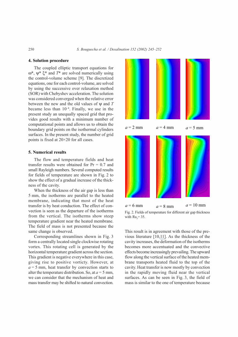
The flow and temperature fields and heattransfer results were obtained for Pr = 0.7 andsmall Rayleigh numbers. Several computed resultsfor fields of temperature are shown in Fig. 2 toshow the effect of a gradual increase of the thick-ness of the cavity.
When the thickness of the air gap is less than5 mm, the isotherms are parallel to the heatedmembrane, indicating that most of the heattransfer is by heat conduction. The effect of con-vection is seen as the departure of the isothermsfrom the vertical. The isotherms show steeptemperature gradient near the heated membrane.The field of mass is not presented because thesame change is observed.
Corresponding streamlines shown in Fig. 3form a centrally located single clockwise rotatingvortex. This rotating cell is generated by thehorizontal temperature gradient across the section.This gradient is negative everywhere in this case,giving rise to positive vorticty. However, ata = 5 mm, heat transfer by convection starts toalter the temperature distribution. So, at a = 5 mm,we can consider that the mechanism of heat andmass transfer may be shifted to natural convection.
a = 2 mm
a = 4 mm
a = 5 mm
a = 6 mm
a = 8 mm
a = 10 mm
Fig. 2. Fields of temperature for different air gap thicknesswith RaT= 35.
This result is in agreement with those of the pre-vious literature [10,11]. As the thickness of thecavity increases, the deformation of the isothermsbecomes more accentuated and the convectiveeffects become increasingly prevailing. The upwardflow along the vertical surface of the heated mem-brane transports heated fluid to the top of thecavity. Heat transfer is now mostly by convectionin the rapidly moving fluid near the verticalsurfaces. As can be seen in Fig. 3, the field ofmass is similar to the one of temperature because

S. Bouguecha et al. / Desalination 152 (2002) 245–252 251
of the similarities between the governing equationsof heat and mass transfer.
The variation of permeate flux with bulktemperature differences is shown in Fig. 4 fordifferent values of feed flow rate Dh. The feedflow rate Dh is calculated as the feed velocitymultiplied by the cell area perpendicular to theliquid flow direction. We note that as thetemperature difference and the feed flow rateincrease, the permeate flux increases. The effectof feed flow rate on permeate flux for differentbulk temperature differences is shown in Fig. 5.The permeate fluxes increase with feed flow rate,
Fig. 3. Fields of temperature (a),mass (b) and streamlinesfor a = 2 mm with RaT= 35.
(a) (b) (c)
Fig. 4. Effect of bulk temperature difference on permeateflux Dc = 0.25 l/min, Tc = 20°C.
0
1
2
3
4
5
6
7
8
0 10 20 30 40 50
n (
kg
/m²s
)
Dh= 0.5 l/mn
Dh= 1 l/mn
Dh= 2 l/mn
∆T (°C)
and they seem to reach maximum values asympto-tically for higher feed flow rate. Furthermore, itwas seen (not shown here) that the flow rate ofcooling water has a small effect on the permeateflux. The effect of air gap thickness on permeateflux for different values of bulk temperaturedifferences is shown in Fig. 6. As indicated in theprevious studies [12,13], the permeate flux decreaseswith increasing the gap thickness, as expectedfrom the gas stagnant film diffusion model [14].
4. Conclusion
Numerical solutions to the Navier–Stokes,mass and energy equations for laminar naturalconvection for the considered cavity have beenobtained for small Rayleigh numbers and usingan elliptic procedure and a control-volume scheme.
Fig. 5. Effect of feed flow rate on permeate flux TC= 20°C,Dc=0.25 l/min.
Fig. 6. Effect of thickness air gape on permeate flux Dh = 2 l/min, Dc = 0.25 l/mn, ∆T = 40°C.
0
1
2
3
4
5
6
7
8
9
0 1 2 3 4 5 6 7 8 9 10
a (mm)
n (
kg
/m²s
)
0
0.5
1
1.5
2
2.5
3
3.5
4
4.5
0 1 2 3
Dh (l/min)
n (
kg
/m²s
)
∆T = 20 °C
∆T = 30 °C
∆T = 40°C
252 S. Bouguecha et al. / Desalination 152 (2002) 245–252
This numerical approach allowed us to analysethe complex natural convection flow situationsarising in the air gap. At a = 5 mm, we note a tran-sition from conduction to convection for the heatand mass transfer in the air gap. The permeateflux is an increasing function of feed flow rateand bulk temperature difference but it decreaseswith increasing gap thickness. The agreementbetween our results and those of the previousstudies can be regarded as satisfactory qualifyingthe model for use in more complex situations.
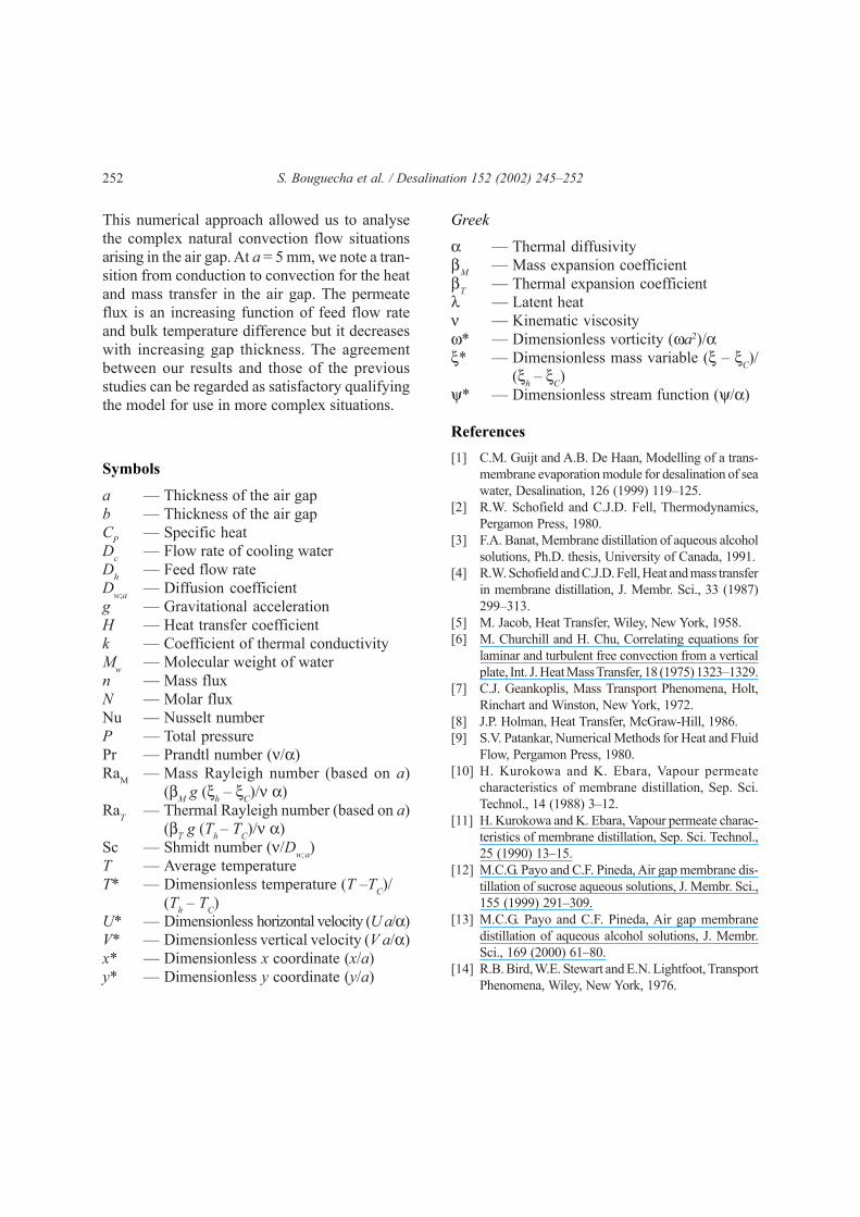
Symbols
a — Thickness of the air gapb — Thickness of the air gapCP — Specific heatDc — Flow rate of cooling waterDh — Feed flow rateDw;a — Diffusion coefficientg — Gravitational accelerationH — Heat transfer coefficientk — Coefficient of thermal conductivityMw — Molecular weight of watern — Mass fluxN — Molar fluxNu — Nusselt numberP — Total pressurePr — Prandtl number (ν/α)RaM — Mass Rayleigh number (based on a)
(βM g (ξh – ξC)/ν α)RaT — Thermal Rayleigh number (based on a)
(βT g (Th – TC)/ν α)Sc — Shmidt number (ν/Dw;a)T — Average temperatureT* — Dimensionless temperature (T –TC)/
(Th – TC)U* — Dimensionless horizontal velocity (U a/α)V* — Dimensionless vertical velocity (V a/α)x* — Dimensionless x coordinate (x/a)y* — Dimensionless y coordinate (y/a)
Greek
α — Thermal diffusivityβM — Mass expansion coefficientβT — Thermal expansion coefficientλ — Latent heatν — Kinematic viscosityω* — Dimensionless vorticity (ωa2)/αξ* — Dimensionless mass variable (ξ – ξC)/
(ξh – ξC)ψ* — Dimensionless stream function (ψ/α)
References[1] C.M. Guijt and A.B. De Haan, Modelling of a trans-
membrane evaporation module for desalination of seawater, Desalination, 126 (1999) 119–125.
[2] R.W. Schofield and C.J.D. Fell, Thermodynamics,Pergamon Press, 1980.
[3] F.A. Banat, Membrane distillation of aqueous alcoholsolutions, Ph.D. thesis, University of Canada, 1991.
[4] R.W. Schofield and C.J.D. Fell, Heat and mass transferin membrane distillation, J. Membr. Sci., 33 (1987)299–313.
[5] M. Jacob, Heat Transfer, Wiley, New York, 1958.[6] M. Churchill and H. Chu, Correlating equations for
laminar and turbulent free convection from a verticalplate, Int. J. Heat Mass Transfer, 18 (1975) 1323–1329.
[7] C.J. Geankoplis, Mass Transport Phenomena, Holt,Rinchart and Winston, New York, 1972.
[8] J.P. Holman, Heat Transfer, McGraw-Hill, 1986.[9] S.V. Patankar, Numerical Methods for Heat and Fluid
Flow, Pergamon Press, 1980.[10] H. Kurokowa and K. Ebara, Vapour permeate
characteristics of membrane distillation, Sep. Sci.Technol., 14 (1988) 3–12.
[11] H. Kurokowa and K. Ebara, Vapour permeate charac-teristics of membrane distillation, Sep. Sci. Technol.,25 (1990) 13–15.
[12] M.C.G. Payo and C.F. Pineda, Air gap membrane dis-tillation of sucrose aqueous solutions, J. Membr. Sci.,155 (1999) 291–309.
[13] M.C.G. Payo and C.F. Pineda, Air gap membranedistillation of aqueous alcohol solutions, J. Membr.Sci., 169 (2000) 61–80.
[14] R.B. Bird, W.E. Stewart and E.N. Lightfoot, TransportPhenomena, Wiley, New York, 1976.