NOMAD Portable Probe User's Manual version 5.4
218
NOMAD Portable Probe Applies to software release v5.4 May 2018 Current documents are always found in the log-in area of the www.bridgetech.tv site. Refer to section 1.2 of this document for more information. DVBCommunity - cообщество профессионалов ЦТВ https://dvbcommunity.ru/
-
Upload
khangminh22 -
Category
Documents
-
view
3 -
download
0
Transcript of NOMAD Portable Probe User's Manual version 5.4

NOMAD Portable ProbeApplies to software release v5.4
May 2018
Current documents are always found in the log-in area of the www.bridgetech.tv site.Refer to section 1.2 of this document for more information.
DVBCommunity - cообщество профессионалов ЦТВ https://dvbcommunity.ru/

NOMAD Portable Probe User’s ManualRevision 550528e (2018-05-07)
Copyright © Bridge Technologies Co AS. Bentsebrugata 20, NO-0476, Oslo, Norway.All rights reserved.
This publication can contain confidential, proprietary, and confidential trade secret information. No part of this documentmay be copied, photocopied, reproduced, translated, or reduced to any machine-readable or electronic format without priorwritten permission from Bridge Technologies Co AS. CE-marked in accordance to low voltage directive (LVC) 73/23/EECand EMC directive 89/336/EEC. Compliant to requirements for US and Canada. Designed for CSA approval. BridgeTechnologies Co AS continuously improves on products and reserves the right to modify the specifications without priornotice. Information in this document is subject to change without notice and Bridge Technologies assumes no responsibilityor liability for any errors or inaccuracies.
The BRIDGE, BRIDGE TECHNOLOGIES and BRIDGETECH name, logo and all other related logos are registeredtrademarks of BRIDGE TECHNOLOGIES Co AS.
All other products or services mentioned in this document are identified by the trademarks, service marks, or productnames as designated by the companies who market those products. Inquiries should be made directly to those companies.This document may also have links to third-party web pages that are beyond the control of Bridge Technologies. Thepresence of such links does not imply that Bridge Technologies Co AS endorses or recommends the content on thosepages. Bridge Technologies acknowledges the use of third-party open source software and licenses in some products.
All trademarks and registered trademarks mentioned herein are the property of their respective owners.
DVBCommunity - cообщество профессионалов ЦТВ https://dvbcommunity.ru/

Contents
Contents 3
1 INTRODUCTION 71.1 About the NOMAD . . . . . . . . . . . . . . . . . . . . . . . . . . . . . . . . . . . . 7
1.1.1 NOMAD – Functionality . . . . . . . . . . . . . . . . . . . . . . . . . . . . . 101.2 How to Use This Manual . . . . . . . . . . . . . . . . . . . . . . . . . . . . . . . . . 11
2 PRINCIPLE OF OPERATION 13
3 SAFETY 15
4 INSTALLATION AND INITIAL SETUP 164.1 Quick Installation Guide . . . . . . . . . . . . . . . . . . . . . . . . . . . . . . . . . 164.2 The NOMAD portable probe . . . . . . . . . . . . . . . . . . . . . . . . . . . . . . . 16
4.2.1 AC Power Supply . . . . . . . . . . . . . . . . . . . . . . . . . . . . . . . . . 164.2.2 Cooling System . . . . . . . . . . . . . . . . . . . . . . . . . . . . . . . . . . 164.2.3 Serial number location . . . . . . . . . . . . . . . . . . . . . . . . . . . . . . 164.2.4 Interfaces . . . . . . . . . . . . . . . . . . . . . . . . . . . . . . . . . . . . . 17
4.3 Powering up the Unit . . . . . . . . . . . . . . . . . . . . . . . . . . . . . . . . . . . 184.4 Initial Configuration . . . . . . . . . . . . . . . . . . . . . . . . . . . . . . . . . . . . 18
4.4.1 Initial Configuration Using the Built-In Wireless Network . . . . . . . . . . . . 194.4.2 Initial Configuration Using the Pre-Set IP-Address . . . . . . . . . . . . . . . 194.4.3 Initial Configuration Via Serial Console Emulated Over USB . . . . . . . . . . 204.4.4 Verifying Correct Initial Setup of the NOMAD . . . . . . . . . . . . . . . . . . 234.4.5 Initial Setup Troubleshooting . . . . . . . . . . . . . . . . . . . . . . . . . . . 23
5 QUICK SETUP GUIDE 255.1 Basic Setup . . . . . . . . . . . . . . . . . . . . . . . . . . . . . . . . . . . . . . . . 255.2 Input Signal Definitions . . . . . . . . . . . . . . . . . . . . . . . . . . . . . . . . . . 25
5.2.1 ASI Input . . . . . . . . . . . . . . . . . . . . . . . . . . . . . . . . . . . . . 255.2.2 Multicasts . . . . . . . . . . . . . . . . . . . . . . . . . . . . . . . . . . . . . 255.2.3 OTT Input (OTT Engine Option Only) . . . . . . . . . . . . . . . . . . . . . . 265.2.4 Demodulator Inputs . . . . . . . . . . . . . . . . . . . . . . . . . . . . . . . 26
5.3 Monitoring . . . . . . . . . . . . . . . . . . . . . . . . . . . . . . . . . . . . . . . . . 265.4 Adjusting Alarm Thresholds . . . . . . . . . . . . . . . . . . . . . . . . . . . . . . . 27
6 THE NOMAD PORTABLE PROBE GRAPHICAL USER INTERFACE 286.1 Main . . . . . . . . . . . . . . . . . . . . . . . . . . . . . . . . . . . . . . . . . . . . 30
6.1.1 Main — Summary . . . . . . . . . . . . . . . . . . . . . . . . . . . . . . . . 306.1.2 Main — CPU usage . . . . . . . . . . . . . . . . . . . . . . . . . . . . . . . 33
NOMAD Portable Probe User’s Manual v5.4 © BRIDGE Technologies Co AS 3
DVBCommunity - cообщество профессионалов ЦТВ https://dvbcommunity.ru/

6.1.3 Main — Thumb overview . . . . . . . . . . . . . . . . . . . . . . . . . . . . . 346.1.4 Main — Eii graphing . . . . . . . . . . . . . . . . . . . . . . . . . . . . . . . 36
6.2 Alarms . . . . . . . . . . . . . . . . . . . . . . . . . . . . . . . . . . . . . . . . . . . 376.2.1 Alarms — All Alarms . . . . . . . . . . . . . . . . . . . . . . . . . . . . . . . 386.2.2 Alarms — Alarm setup . . . . . . . . . . . . . . . . . . . . . . . . . . . . . . 396.2.3 Alarms — Flash Alarms (FLASH option) . . . . . . . . . . . . . . . . . . . . 45
6.3 OTT . . . . . . . . . . . . . . . . . . . . . . . . . . . . . . . . . . . . . . . . . . . . 466.3.1 OTT — Active testing . . . . . . . . . . . . . . . . . . . . . . . . . . . . . . . 466.3.2 OTT — Details . . . . . . . . . . . . . . . . . . . . . . . . . . . . . . . . . . 47
6.3.2.1 OTT — Details — Profiles . . . . . . . . . . . . . . . . . . . . . . . 486.3.2.2 OTT — Details — Manifest . . . . . . . . . . . . . . . . . . . . . . 506.3.2.3 OTT — Details — Alarms . . . . . . . . . . . . . . . . . . . . . . . 526.3.2.4 OTT — Details — Thumbnails . . . . . . . . . . . . . . . . . . . . 536.3.2.5 OTT — Details — Alignment . . . . . . . . . . . . . . . . . . . . . 54
6.3.3 OTT — Latency . . . . . . . . . . . . . . . . . . . . . . . . . . . . . . . . . . 556.3.4 OTT — Channels . . . . . . . . . . . . . . . . . . . . . . . . . . . . . . . . . 566.3.5 OTT — Settings . . . . . . . . . . . . . . . . . . . . . . . . . . . . . . . . . 586.3.6 OTT — Thresholds . . . . . . . . . . . . . . . . . . . . . . . . . . . . . . . . 59
6.4 Multicasts . . . . . . . . . . . . . . . . . . . . . . . . . . . . . . . . . . . . . . . . . 616.4.1 Multicasts — Parameters . . . . . . . . . . . . . . . . . . . . . . . . . . . . . 616.4.2 Multicasts — Parameters — Fields . . . . . . . . . . . . . . . . . . . . . . . 716.4.3 Multicasts — Summary . . . . . . . . . . . . . . . . . . . . . . . . . . . . . . 716.4.4 Multicasts — History . . . . . . . . . . . . . . . . . . . . . . . . . . . . . . . 736.4.5 Multicasts — Join . . . . . . . . . . . . . . . . . . . . . . . . . . . . . . . . . 746.4.6 Multicasts — Streams . . . . . . . . . . . . . . . . . . . . . . . . . . . . . . 756.4.7 Multicasts — Ethernet thresh. . . . . . . . . . . . . . . . . . . . . . . . . . . 79
6.5 MW (Media Window) . . . . . . . . . . . . . . . . . . . . . . . . . . . . . . . . . . . 826.5.1 Media Window — Selected channel . . . . . . . . . . . . . . . . . . . . . . . 836.5.2 Media Window — Bandwidth graph . . . . . . . . . . . . . . . . . . . . . . . 846.5.3 Media Window — Inter Arrival Time graph . . . . . . . . . . . . . . . . . . . 85
6.6 RDP (Return Data Path) . . . . . . . . . . . . . . . . . . . . . . . . . . . . . . . . . 856.6.1 RDP — Control . . . . . . . . . . . . . . . . . . . . . . . . . . . . . . . . . . 856.6.2 RDP — Setup . . . . . . . . . . . . . . . . . . . . . . . . . . . . . . . . . . . 86
6.7 Traffic . . . . . . . . . . . . . . . . . . . . . . . . . . . . . . . . . . . . . . . . . . . 886.7.1 Traffic — Protocols . . . . . . . . . . . . . . . . . . . . . . . . . . . . . . . . 886.7.2 Traffic — Detect . . . . . . . . . . . . . . . . . . . . . . . . . . . . . . . . . . 896.7.3 Traffic — Filter statistics . . . . . . . . . . . . . . . . . . . . . . . . . . . . . 916.7.4 Traffic — Filter setup . . . . . . . . . . . . . . . . . . . . . . . . . . . . . . . 936.7.5 Traffic — Microbitrate . . . . . . . . . . . . . . . . . . . . . . . . . . . . . . . 95
6.8 Ethernet . . . . . . . . . . . . . . . . . . . . . . . . . . . . . . . . . . . . . . . . . . 966.8.1 Ethernet — FSM . . . . . . . . . . . . . . . . . . . . . . . . . . . . . . . . . 96
6.8.1.1 Ethernet — FSM — Monitor . . . . . . . . . . . . . . . . . . . . . . 976.8.1.2 Ethernet — FSM — Setup . . . . . . . . . . . . . . . . . . . . . . 986.8.1.3 Ethernet — FSM — Syslog . . . . . . . . . . . . . . . . . . . . . . 100
6.8.2 Ethernet — IGMP . . . . . . . . . . . . . . . . . . . . . . . . . . . . . . . . 1016.8.3 Ethernet — PCAP . . . . . . . . . . . . . . . . . . . . . . . . . . . . . . . . 102
6.9 ETR 290 . . . . . . . . . . . . . . . . . . . . . . . . . . . . . . . . . . . . . . . . . . 1036.9.1 ETR 290 — ETR Overview . . . . . . . . . . . . . . . . . . . . . . . . . . . . 1036.9.2 ETR 290 — ETR Details . . . . . . . . . . . . . . . . . . . . . . . . . . . . . 104
4 NOMAD Portable Probe User’s Manual v5.4 © BRIDGE Technologies Co AS
DVBCommunity - cообщество профессионалов ЦТВ https://dvbcommunity.ru/

6.9.3 ETR 290 — PIDs . . . . . . . . . . . . . . . . . . . . . . . . . . . . . . . . . 1076.9.4 ETR 290 — Services . . . . . . . . . . . . . . . . . . . . . . . . . . . . . . . 1086.9.5 ETR 290 — Bitrates . . . . . . . . . . . . . . . . . . . . . . . . . . . . . . . 1126.9.6 ETR 290 — Tables . . . . . . . . . . . . . . . . . . . . . . . . . . . . . . . . 1136.9.7 ETR 290 — PCR . . . . . . . . . . . . . . . . . . . . . . . . . . . . . . . . . 1156.9.8 ETR 290 — T2MI (requires T2MI-OPT) . . . . . . . . . . . . . . . . . . . . . 1176.9.9 ETR 290 — SCTE 35 (requires SCTE35-OPT) . . . . . . . . . . . . . . . . . 1216.9.10 ETR 290 — Status . . . . . . . . . . . . . . . . . . . . . . . . . . . . . . . . 1236.9.11 ETR 290 — Compare . . . . . . . . . . . . . . . . . . . . . . . . . . . . . . 1236.9.12 ETR 290 — ETR threshold . . . . . . . . . . . . . . . . . . . . . . . . . . . . 1286.9.13 ETR 290 — PID thresholds . . . . . . . . . . . . . . . . . . . . . . . . . . . 1396.9.14 ETR 290 — Service thresh. . . . . . . . . . . . . . . . . . . . . . . . . . . . 1416.9.15 ETR 290 — Gold TS thresholds . . . . . . . . . . . . . . . . . . . . . . . . . 144
6.10 ASI . . . . . . . . . . . . . . . . . . . . . . . . . . . . . . . . . . . . . . . . . . . . . 1496.10.1 ASI — Status . . . . . . . . . . . . . . . . . . . . . . . . . . . . . . . . . . . 1506.10.2 ASI — Setup . . . . . . . . . . . . . . . . . . . . . . . . . . . . . . . . . . . 151
6.11 COFDM/QAM . . . . . . . . . . . . . . . . . . . . . . . . . . . . . . . . . . . . . . . 1526.11.1 COFDM/QAM — Status . . . . . . . . . . . . . . . . . . . . . . . . . . . . . 1526.11.2 COFDM/QAM — Tuning setup . . . . . . . . . . . . . . . . . . . . . . . . . . 1586.11.3 COFDM/QAM — COFDM/QAM threshold . . . . . . . . . . . . . . . . . . . 1606.11.4 COFDM/QAM — Impulse response (Requires Advanced RF Option) . . . . . 1636.11.5 COFDM/QAM — RF overview . . . . . . . . . . . . . . . . . . . . . . . . . . 164
6.12 SAT . . . . . . . . . . . . . . . . . . . . . . . . . . . . . . . . . . . . . . . . . . . . 1646.12.1 SAT — Status . . . . . . . . . . . . . . . . . . . . . . . . . . . . . . . . . . . 1656.12.2 SAT — Tuning setup . . . . . . . . . . . . . . . . . . . . . . . . . . . . . . . 1686.12.3 SAT — Frequency scan . . . . . . . . . . . . . . . . . . . . . . . . . . . . . 1706.12.4 SAT — SAT threshold . . . . . . . . . . . . . . . . . . . . . . . . . . . . . . 1716.12.5 SAT — RF overview . . . . . . . . . . . . . . . . . . . . . . . . . . . . . . . 173
6.13 Setup . . . . . . . . . . . . . . . . . . . . . . . . . . . . . . . . . . . . . . . . . . . 1746.13.1 Setup — Params . . . . . . . . . . . . . . . . . . . . . . . . . . . . . . . . . 1746.13.2 Setup — Pages . . . . . . . . . . . . . . . . . . . . . . . . . . . . . . . . . . 1766.13.3 Setup — Colors (requires EXTRACT-OPT) . . . . . . . . . . . . . . . . . . . 1766.13.4 Setup — Time . . . . . . . . . . . . . . . . . . . . . . . . . . . . . . . . . . 1776.13.5 Setup — Ethernet . . . . . . . . . . . . . . . . . . . . . . . . . . . . . . . . 178
6.13.5.1 Setup — Ethernet — IPv6 Settings . . . . . . . . . . . . . . . . . . 1806.13.5.2 Example 1 – Separate Management IPv4 . . . . . . . . . . . . . . 1816.13.5.3 Example 2 – In-Line Management IPv4 . . . . . . . . . . . . . . . 1816.13.5.4 Example 3 – Mixed Mode IPv4 . . . . . . . . . . . . . . . . . . . . 182
6.13.6 Setup — WiFi . . . . . . . . . . . . . . . . . . . . . . . . . . . . . . . . . . . 1836.13.7 Setup — VLANs . . . . . . . . . . . . . . . . . . . . . . . . . . . . . . . . . 1846.13.8 Setup — VBC . . . . . . . . . . . . . . . . . . . . . . . . . . . . . . . . . . . 1856.13.9 Setup — Login . . . . . . . . . . . . . . . . . . . . . . . . . . . . . . . . . . 185
6.13.9.1 Access Control Lists . . . . . . . . . . . . . . . . . . . . . . . . . . 1866.13.10Setup — ETR . . . . . . . . . . . . . . . . . . . . . . . . . . . . . . . . . . . 1876.13.11Setup — VBC thresh. . . . . . . . . . . . . . . . . . . . . . . . . . . . . . . 1906.13.12Setup — Scheduling . . . . . . . . . . . . . . . . . . . . . . . . . . . . . . . 1926.13.13Setup — Routing . . . . . . . . . . . . . . . . . . . . . . . . . . . . . . . . . 1936.13.14Setup — Security . . . . . . . . . . . . . . . . . . . . . . . . . . . . . . . . . 194
6.14 Data . . . . . . . . . . . . . . . . . . . . . . . . . . . . . . . . . . . . . . . . . . . . 196
NOMAD Portable Probe User’s Manual v5.4 © BRIDGE Technologies Co AS 5
DVBCommunity - cообщество профессионалов ЦТВ https://dvbcommunity.ru/

6.14.1 Data — Configuration . . . . . . . . . . . . . . . . . . . . . . . . . . . . . . 1966.14.2 Data — Software . . . . . . . . . . . . . . . . . . . . . . . . . . . . . . . . . 1976.14.3 Data — Table Descriptors . . . . . . . . . . . . . . . . . . . . . . . . . . . . 1986.14.4 Data — Eii . . . . . . . . . . . . . . . . . . . . . . . . . . . . . . . . . . . . 1996.14.5 Data — Storage (FLASH option) . . . . . . . . . . . . . . . . . . . . . . . . . 199
6.15 About . . . . . . . . . . . . . . . . . . . . . . . . . . . . . . . . . . . . . . . . . . . 2006.15.1 About — Release info . . . . . . . . . . . . . . . . . . . . . . . . . . . . . . 2006.15.2 About — License . . . . . . . . . . . . . . . . . . . . . . . . . . . . . . . . . 2006.15.3 About — Technologies . . . . . . . . . . . . . . . . . . . . . . . . . . . . . . 2016.15.4 About — Credits . . . . . . . . . . . . . . . . . . . . . . . . . . . . . . . . . 201
A Appendix: NOMAD Versus VBC Alarms 203
B Appendix: Monitoring Practices 205B.1 RTP Monitoring . . . . . . . . . . . . . . . . . . . . . . . . . . . . . . . . . . . . . . 205B.2 Default Multicast Monitoring . . . . . . . . . . . . . . . . . . . . . . . . . . . . . . . 205B.3 Strategy for MediaWindow Analysis . . . . . . . . . . . . . . . . . . . . . . . . . . . 206
B.3.1 IAT Before and After Router . . . . . . . . . . . . . . . . . . . . . . . . . . . 207B.3.2 Identifying UDP Packet Loss . . . . . . . . . . . . . . . . . . . . . . . . . . . 208
B.4 Multicast Thresholds . . . . . . . . . . . . . . . . . . . . . . . . . . . . . . . . . . . 209B.5 Dedicated interface for OTT . . . . . . . . . . . . . . . . . . . . . . . . . . . . . . . 209B.6 OTT descrambling with Verimatrix . . . . . . . . . . . . . . . . . . . . . . . . . . . . 210B.7 OTT Bandwidth requirements . . . . . . . . . . . . . . . . . . . . . . . . . . . . . . 210
C Appendix: OTT Profile Health 211C.1 OTT Profile Health Bar . . . . . . . . . . . . . . . . . . . . . . . . . . . . . . . . . . 211C.2 OTT Profile Health Timeline . . . . . . . . . . . . . . . . . . . . . . . . . . . . . . . 211
D Appendix: Software Maintenance 213
E Appendix: Software Upload 214E.1 Obtain the software image . . . . . . . . . . . . . . . . . . . . . . . . . . . . . . . . 214E.2 Export and save the probe configuration . . . . . . . . . . . . . . . . . . . . . . . . 214E.3 Delete any existing probe stream recordings . . . . . . . . . . . . . . . . . . . . . . 214E.4 Transfer the image to the probe and save to flash . . . . . . . . . . . . . . . . . . . . 215E.5 Wait while the software is being saved . . . . . . . . . . . . . . . . . . . . . . . . . . 217E.6 Verify the new image . . . . . . . . . . . . . . . . . . . . . . . . . . . . . . . . . . . 217E.7 Software upload troubleshooting . . . . . . . . . . . . . . . . . . . . . . . . . . . . . 217
F Appendix: Restoring NOMAD factory defaults 218
6 NOMAD Portable Probe User’s Manual v5.4 © BRIDGE Technologies Co AS
DVBCommunity - cообщество профессионалов ЦТВ https://dvbcommunity.ru/

1 INTRODUCTION
1.1 About the NOMAD
NOMAD covers all the monitoring needs encountered in hybrid IP multicast, OTT and RF networks. Itis the ultimate all-in-one monitoring and analysis solution for the technician on the move.
NOMAD is a breakthrough design with almost every conceivable interface for media signal monitoringand analysis. Featuring optical/electrical Gigabit Ethernet, ASI in/out, DVB-C QAM cable, DVB-T/T2COFDM terrestrial, DVB-S/S2 satellite and external 1PPS GPS time-reference, NOMAD can analyseall RF transmitted DVB signals as well as OTT and multicast/unicast IP transmissions.
With comprehensive IP packet analysis tools, NOMAD is ideal for IP transport understanding regard-less of media transported. NOMAD also is shipped with the ultimate in user friendly setup. The unitcontains a Wi-Fi zone, and by pointing a laptop towards this, NOMAD is ready for use without furtherconfiguration.
As technologies become more and more complex, using NOMAD will give invaluable insight intomodern media signal behaviours without the need for deep operator knowledge of the media tech-nology used. Cut from a single brick of aluminium, NOMAD sets a new standard for both finish andruggedness. It is also of very light weight and is the perfect companion to a laptop.
NOMAD ships with extensive functionality for superior digital media understanding right out of thebox. Additionally NOMAD has a substantial additional set of extended analysis options, enabling it tooutperform the most comprehensive systems on the market in functionality. This also allows NOMADto be an ideal laboratory tool for desktop analysis in the most demanding environments. NOMADalso sets a new benchmark of affordability in the industry.
Designed to replace old-school PCI cards, USB-based dongles and other laptop-dependent devices,NOMAD is a complete free-standing unit with its own CPU and can be left to monitor signals by itselfwithout the need for a host system.
Interfaces
NOMAD features three Gigabit Ethernet ports. One of these is for management; one with a choiceof optical or electrical; and a third optional electrical port, ASI in/out, DVB-C QAM cable, DVB-T/T2COFDM terrestrial, DVB-S/S2 satellite and external 1PPS GPS time-reference.
The unit can analyse all RF transmitted DVB signals as well as OTT and multicast/unicast IPtransmissions. With comprehensive IP packet analysis tools, NOMAD is ideal for IP transportunderstanding regardless of media transported.
NOMAD Portable Probe User’s Manual v5.4 © BRIDGE Technologies Co AS 7
DVBCommunity - cообщество профессионалов ЦТВ https://dvbcommunity.ru/
Ethernet
• 10/100/1000T Gigabit Ethernet interface for video/data analysis
• SFP port for optical Gigabit connectivity
• Optional second Gigabit Ethernet port
• Web-based management interface optionally on all ports
• SSH/TELNET terminal
• Relay video multicasts to 3rd party targets using RDP
• Laser power received level for fault finding on SFP
WiFi
• Provides 2.4 GHz Wireless Access Point service
• No setup - NOMAD is WiFi Zone
• USB 2.0 IEEE 802.11 b/g/n 150Mbit/s dongle
DVB-S/S2 satellite
• Supports DVB-S and DVB-S2 8PSK, 16APSK, 32APSK, GOLD CODES
• L-band input from 950 - 2160 MHz
• Symbol rate range between 1 - 45 MS/s
• 13V/18V/22kHz and DiseqC 1.0 capable for switch control
• High-end RF performance with constellation diagram and over 20 RF parameters
• Auto-scan feature
DVB-T/T2/C terrestrial and cable
• Supports DVB-T EN 300-744 and DVB-T2 EN-302-755 (v1.3.1)
• Supports ITU.T J.83 Annex A/C for cable networks (QAM16 up to QAM256)
• Frequency range: 43 - 1002 MHz. Bandwidth 5, 6, 7 and 8 MHz
• Channel Impulse Response diagram and constellation diagram for DVB-T/T2
1PPS
• Offers GPS syncronization down to 0.1 us accuracy
• Allows absolute network delay in SFN/T2MI networks to be measured
• Allows absolute Center Frequency Offset measurements on DVB-T/T2
8 NOMAD Portable Probe User’s Manual v5.4 © BRIDGE Technologies Co AS
DVBCommunity - cообщество профессионалов ЦТВ https://dvbcommunity.ru/

ASI
• ASI input according to EN 50083-9, Annex B
• Supports Burst mode, Spread Mode and legacy M2S
• Output selectable feed from ASI, DVB-T/T2/C or DVB-S/S2 input
• Up to 211Mbit/s incoming rate (linespeed ASI)
Analytics
Through packet inspection, TS analysis is built in with the award-winning ETR290 Engine, enablingdeep understanding of TS streams. IP packet traffic is viewed in real-time, and broken down intoindividual protocols, giving an unprecedented and simplified understanding of otherwise complexstructures in the transport mechanics.
Total passing of OTT multiscreen playlist and manifest files secures coherence and standards, withfull insight into chunk availability, download times, sequence latency, profile alignment and much more.NOMAD is at the forefront of HLS and DASH understanding and analytics. The same goes for thediverse RF interfaces. Full RF metrics, with best-in-class specifications, visualisations of constellationdiagrams and advanced analytics like reflections in digital terrestrial networks are all examples ofadvanced functions not normally found in affordable equipment of this class.
Technologies
NOMAD features a plethora of award-winning and patented technologies, the culmination of 12 yearsof accumulated engineering knowledge and R& D in IP and broadcast monitoring. The NOMADuser interface is via the Bridge Technologies’ patented MediaWindow visualisation technology, whichallows complex structures and data to be readily understood by non-expert users, enabling them toidentify appropriate corrective actions quickly and easily.
Web interface Intuitive GUI for remote access via Wi-Fi or cabled EthernetPacket analysis Accurate packet behaviour, IAT histogram, protocol analysis
and traffic, autodetection of IP uni/multicast
OTT/Multiscreen HLS, HDS, M-DASH, SmoothStream™, RTMP, SHOUT-cast™, post-CDN URL token support and manifest valida-tion. Innovative framework for measuring delay of OTT ser-vice through distribution chain
Multicast/unicast IP Microsecond-accurate and detailed multicast packet moni-toring, analysis and alarming with readout and alarming onkey parameters relevant to video
RDP™ forwarding and recording Return Data Path forwarding of any transport stream moni-tored with automated alarm triggered recording to 32GB ofon-board Flash memory
Gold TS™ Innovative Gold TS framework: part of the award-winningETR290 Engine for recording a perfect transport streamtable set and then can be compared and alarmed against atemplate
NOMAD Portable Probe User’s Manual v5.4 © BRIDGE Technologies Co AS 9
DVBCommunity - cообщество профессионалов ЦТВ https://dvbcommunity.ru/

Powerful IP tools ICMP PING and TraceRoute can be done from inside alocation remotely and PING can be setup to alarm if remotedevice stops responding
Media format support MPEG2-TS. H.264/AVC HD, H265/HEVC 4K, AAC, PCMAudio, SCTE-35 signaling, T2-MI encapsulation and more
Media window™ Total packet understanding with the patented MediaWin-dow™ visualisation technology for RTP/UDP uni- and multi-casts
ETR290 analytics The award-winning ETR290 Engine with detailed analytics ofPriority 1, 2 and 3 tests plus extensions to test CA behaviour,alarm history view, timeline view and much more
Design
Built from a single piece of high quality aluminium, NOMAD provides the ruggedness necessary inharsh outdoor broadcast and telecom environments, and at the same time provides unprecedentedaesthetics and functionality.
CNC-milled with a precision down to 10 micron, laser engraved logotypes and a form factor resemblinga solid tablet, NOMAD stands on recessed rubber feet, allowing the unit to hover 0,2 millimetres overany surface. All heat from the advanced processors is dispersed through its aluminium chassis, andwith exceptional electronics design, the unit provides amazing abilities for the digital media engineer.
1.1.1 NOMAD – Functionality
An IP-based network is fully transparent with respect to signal contents quality, provided that theIP packets arrive, and provided that they arrive in time. The NOMAD therefore uses the patentedMediaWindow to allow monitoring at-a-glance of packet loss and errors in inter-packet arrival time.This way the operator can conveniently ensure correct signal quality at IP-level.
The advanced Ethernet protocol analysis tool automatically detects all protocols carried over Ethernetpast the port the NOMAD is connected to, and it displays statistics like percentage utilization of theinterface and percentage of the different transported protocols. This gives the NOMAD a real-timesniffer capability.
The NOMAD allows the user to define a Return Data Path (RDP), using the regular video/datanetwork or the management network to return a stream. A faulty signal can then be further analyzedat the studio premises, when necessary.
The recording functionality allows the user to record a stream, either triggered manually by the useror triggered by a user defined alarm.
10 NOMAD Portable Probe User’s Manual v5.4 © BRIDGE Technologies Co AS
DVBCommunity - cообщество профессионалов ЦТВ https://dvbcommunity.ru/

Full Service Monitoring (FSM) checks that vital system components like CA-servers are active.
Ethernet TR 290 monitoring allows the operator to check parameters like transport stream sync andPSI/SI standards conformity. This option also performs further PSI/SI analysis, making it possible toview PSI/SI contents. PID and service bitrates are also continuously measured.
OTT monitoring allows the operator to set up active testing of Over-the-top type signals as foundin adaptive bitrate streaming architectures. Formats supported include Apple ™ HLS, Microsoft ™Smoothstream, RTMP, MPEG DASH, Adobe ™ HDS and Nullsoft SHOUTcast™.
The NOMAD can be expanded through license options to monitor the T2MI protocol layer as found inDVB-T2 networks.
The NOMAD can also be licensed with an SCTE 35 option that allows monitoring and logging ofsplice time codes embedded in the transport streams.
1.2 How to Use This Manual
This User’s Manual is valid for software version 5.4 of the NOMAD portable probe.
Throughout this manual the term stream is often used rather than unicast or multicast. One streammay consist of one or more services, and refers to one IP uni- or multicast (for Ethernet input) or onetransport stream (ASI, COFDM, QAM/VSB or QPSK/DVB-S2).
Chapter 2 PRINCIPLE OF OPERATION provides a simplified block-diagram overview of the probe.
Chapter 3 SAFETY lists safety precautions, and this chapter should be read prior to equipmentinstallation.
Chapter 4 INSTALLATION AND INITIAL SETUP explains how to install the equipment in a rack, andalso how to perform the necessary initial configuration of the NOMAD management IP address. Astep-by-step quick installation guide is found in section 4.1.
NOMAD Portable Probe User’s Manual v5.4 © BRIDGE Technologies Co AS 11
DVBCommunity - cообщество профессионалов ЦТВ https://dvbcommunity.ru/

Chapter 5 QUICK SETUP GUIDE contains a quick setup guide; a step-by-step description of how tosetup the NOMAD once the initial setup has been performed.
Chapter 6 THE NOMAD PORTABLE PROBE GRAPHICAL USER INTERFACE describes the graphi-cal user interface (GUI) as seen when pointing a web browser to the NOMAD’s IP address.
A Appendix: NOMAD Versus VBC Alarms describes the alarm handling in the NOMAD versus theVBC Controller.
B Appendix: Monitoring Practices explains some useful monitoring practices.
C Appendix: OTT Profile Health explains the OTT profile health bar and timeline.
D Appendix: Software Maintenance briefly describes software maintenance licenses and how theyare used.
E Appendix: Software Upload explains how to upgrade the software on the NOMAD.
F Appendix: Restoring NOMAD factory defaults details how to reset the NOMAD to factory defaultsettings.
Note that current version of the User’s Manual can be found on the http://www.bridgetech.tv/website. Log in as end user: customer with password: xmas4u. Additional technical documentationis also found at the same location.
12 NOMAD Portable Probe User’s Manual v5.4 © BRIDGE Technologies Co AS
DVBCommunity - cообщество профессионалов ЦТВ https://dvbcommunity.ru/

2 PRINCIPLE OF OPERATION
The probe module is equipped with two RJ45 Ethernet ports and one SFP optical port. The userselects which transport stream signal input to be used by the monitoring engine, either the Ethernetvideo/data port or the SFP optical input. Management of the probe is conducted via the Ethernetmanagement port or alternatively in-band via the video/data ports.
NOMAD Module
Monitoring Engine
SFP Video/Data *
RJ45 Video/Data *
ASI Input
ASI Output
Demodulator Input(s)
1PPS
Ethernet Management
SNMP Traps
* Optional license enables simultaneoususe of RJ45 and SFP monitoring inputs
Figure 2.1: The NOMAD Module – Principle of Operation
A simplified diagram of the alarm handling mechanisms of the NOMAD is shown in figure 2.2. Theinput signals are continuously analyzed, and measured data are checked against user definedthreshold values. If the data do not comply with the threshold values alarms will be generated.The overall alarm settings further make it possible to enable and disable alarms, thus definingwhich alarms should be reported in the NOMAD alarm list and sent as SNMP traps to an externalmanagement system.
NOMAD Portable Probe User’s Manual v5.4 © BRIDGE Technologies Co AS 13
DVBCommunity - cообщество профессионалов ЦТВ https://dvbcommunity.ru/

SignalMeasurements
ThresholdSettings
AlarmSettings
SNMPAlarms
AlarmLists
Figure 2.2: Simplified Diagram of the Alarm Handling in the NOMAD
14 NOMAD Portable Probe User’s Manual v5.4 © BRIDGE Technologies Co AS
DVBCommunity - cообщество профессионалов ЦТВ https://dvbcommunity.ru/

3 SAFETY
Read the installation instructions before connecting the chassis unit to the power source.
The NOMAD is intended for installation in restricted access areas. A restricted access areacan be accessed only through the use of a special tool, lock and key, or other means ofsecurity.
The NOMAD must only be used with the included power supply. Do not use the power supplyif it or its cables are damaged.
Only trained and qualified personnel should be allowed to install, replace or service thisequipment.
This equipment must be installed and maintained by service personnel as defined by AS/NZS3260. Incorrectly connecting this equipment to a general-purpose outlet could be hazardous.
If SFP modules are used ensure proper precautions are taken to protect eyes against harmfulinfrared radiation. Do not look straight into the SFP module or fibers connected to the SFPmodule. The SFP modules employed are certified in Laser Class 1.
Ultimate disposal of this product should be handled according to all national laws and regu-lations.
To prevent the system from overheating, do not operate it in an area that exceeds the max-imum ambient temperature of 45 degrees Celsius. Do not place other objects on top of theNOMAD as this may cause heat to build up which could damage the unit. Air needs to flowfreely underneath the unit so make sure that the feet of the unit are intact.
Do not work on the system or connect or disconnect cables during periods of lightning ac-tivity.
The NOMAD requires short-circuit (overcurrent) protection. Ensure that the protective deviceis rated not greater than 120 VAC, 15 A; 240 VAC, 16 A.
NOMAD Portable Probe User’s Manual v5.4 © BRIDGE Technologies Co AS 15
DVBCommunity - cообщество профессионалов ЦТВ https://dvbcommunity.ru/

4 INSTALLATION AND INITIAL SETUP
4.1 Quick Installation Guide
1. Read the safety instructions, refer to chapter 3
2. Connect the signal cables, refer to section 4.2.4
3. Power up the unit, refer to section 4.3
4. Perform initial set-up of IP addresses, refer to section 4.4
5. Verify that the GUI launches correctly, refer to section 4.4.4
4.2 The NOMAD portable probe
The NOMAD portable probe is built for real world use. Its ruggedized exterior and fan-less designgives engineers the perfect fault-finding tool when roaming in the network or for permanent placementin a harsh environment.
4.2.1 AC Power Supply
The portable chassis is delivered with an external 100–240V AC power supply. The NOMAD mustonly be used with the included power supply. Do not use the power supply if it or its cablesare damaged.
4.2.2 Cooling System
The portable unit uses passive cooling and the chassis act as a heat sink. Do not place otherobjects on top of the NOMAD as this may cause heat to build up which could damage theunit. Air needs to flow freely underneath the unit so make sure that the feet of the unit areintact.
4.2.3 Serial number location
The serial number is located at the bottom of the unit. All serial numbers can also be found on theshipping box.
The serial number of the NOMAD probe is also available via the web GUI under About — License.
16 NOMAD Portable Probe User’s Manual v5.4 © BRIDGE Technologies Co AS
DVBCommunity - cообщество профессионалов ЦТВ https://dvbcommunity.ru/

Figure 4.1: The NOMAD portable probe
4.2.4 Interfaces
Figure 4.2: NOMAD front connectors
The NOMAD module is equipped with the following connectors on the front:
USB-WiFi: The USB port port used for the WiFi connection. Only the WiFi adapterincluded with the device can be used in this port
DATA A:(10/100/1000T)
For monitoring a 10/100/1000 electrical/copper signal – RJ-45.The probe can only monitor either the SFP input signal OR the10/100/1000T input signal (selected from software), unless licensed touse both inputs.
NOMAD Portable Probe User’s Manual v5.4 © BRIDGE Technologies Co AS 17
DVBCommunity - cообщество профессионалов ЦТВ https://dvbcommunity.ru/

MANAGEMENT:(10/100/1000T)
Interface for running management of the probe on a separate network.The management can also be done using the data ports (if enabled).The interface is RJ45 and supports 10/100/1000T.
DATA B:(SFP)
Alternative SFP input used when connecting to optical networks. Canalso be used with an electrical SFP module to monitor two RJ45 portsin parallel. The probe can only monitor either the SFP input signalOR the 10/100/1000T input signal (selected from software), unlesslicensed to use both inputs.
ASI OUTPUT: ASI transport stream output – 75 ohm BNC female
ASI INPUT: ASI transport stream input – 75 ohm BNC female
RF A:(DVB-S/DVB-S2)
RF L-band input with DiSEqC 1.2 – 75 ohm F-connector for monitoringsatellite signals. Supported standards are DVB-S and DVB-S2.
RF B:(DVB-T/DVB-T2/DVB-C)
RF input – 75 ohm F-connector for monitoring terrestrial and cable TVsignals. Supported standards are DVB-T, DVB-T2 and DVB-C.
1PPS: 1PPS reference clock input – 50 ohm SMA female
Figure 4.3: NOMAD back connectors
The NOMAD module is equipped with the following connectors on the back:
POWER 12V 5A: The power input to the probe. Only use the included 12V/5A power supply
SERIAL: USB serial port emulator for initial set-up of the probe – Type A
4.3 Powering up the Unit
For the NOMAD, connect the power supply to the mains source and the power supply to the probe.The diodes should then light up and the unit will boot.
Note that it will take some time from power-up until the modules can be accessed via the managementinterface – typically the start-up may take up to two minutes.
4.4 Initial Configuration
There are three alternative ways of performing an initial configuration of the probe module:
18 NOMAD Portable Probe User’s Manual v5.4 © BRIDGE Technologies Co AS
DVBCommunity - cообщество профессионалов ЦТВ https://dvbcommunity.ru/

1. Via the built-in NOMAD wireless management network
2. By using the preconfigured IP address of the probe management port
3. Via serial console emulated over USB
For most users the one of the first two methods will be the easiest.
4.4.1 Initial Configuration Using the Built-In Wireless Network
Figure 4.4: Configuring the NOMAD wireless network
A brand new NOMAD is accessible as a passwordless Access Point and requires initial configurationin order to secure access to it. For that reason the first time you boot up your device and open WebUI,it will suggest to change the Access Point settings before you proceed further. After you connect toyour NOMAD’s Access Point, the popup window with the WiFi initial configuration appears. If it hasnot happened open a browser manually and go to http://192.168.1.1/. This will open the initialconfiguration page, as shown in figure 4.4.
If you do not want to use wireless access to your NOMAD, just disable the Access Point (seefigure 4.4) and apply settings.
It is strongly recommended to change the default settings and set at least security method andpassword.
Also it is a good idea to store a bookmark in your browser pointing to your NOMAD, since you mayforget its address over the time and will have to connect to it using an alternative method (e.g wirednetwork interface).
Please refer to chapter 6.13.6 for more details on how to configure the wireless network.
4.4.2 Initial Configuration Using the Pre-Set IP-Address
The NOMAD modules are shipped with the following factory settings for the wired managementinterface:
Management (eth1) IP address: 10.0.20.101
Management (eth1) subnet mask: 255.255.0.0
In order to connect to the eth1 management port, the PC used for set-up should have corresponding
NOMAD Portable Probe User’s Manual v5.4 © BRIDGE Technologies Co AS 19
DVBCommunity - cообщество профессионалов ЦТВ https://dvbcommunity.ru/

Figure 4.5: Setting the IP address manually in Windows
network settings. Typically a lap-top PC is used for initial configuration. Connect directly to thedevice’s eth1 management port using an Ethernet cable.
For Windows, the network parameters are set in the Control Panel — Network and Internet— Network and Sharing Center — Network Connection — Properties — Internet ProtocolVersion 4 Properties view, as shown in figure 4.5. Select the user defined address, and set the PC’sIP address to 10.0.20.100 and the subnet mask to 255.255.0.0.
When the IP address of the PC has been set to match the NOMAD factory setting, the permanentnetwork settings can be configured through the NOMAD web browser interface. Refer to sections4.4.4 and 6.13.5 for details on how to launch the NOMAD graphical user interface and how to set thenetwork parameters.
4.4.3 Initial Configuration Via Serial Console Emulated Over USB
If the NOMAD for some reason cannot be reached through Ethernet or Wireless communication, theinitial set-up may be performed via serial console emulated over USB. For the initial set-up, you mustdo the following:
1. Installing a driver for the USB communication, if not already supported by the operating system
2. Setting the management IP address
Most operating systems will have native support for the FT232 driver needed. When a USB cableis connected between a PC and the NOMAD, the operating system will detect a new USB device.
20 NOMAD Portable Probe User’s Manual v5.4 © BRIDGE Technologies Co AS
DVBCommunity - cообщество профессионалов ЦТВ https://dvbcommunity.ru/

Figure 4.6: Connecting to the serial console over USB
For Windows, the new device will appear as a COM port in the Device Manager view as shown infigure 4.6.
If your operating system does not detect the NOMAD, you may have to download and install a driver forit. The driver may be downloaded directly from the chip manufacturer at http://www.ftdichip.com/.Select first Drivers, then VCP followed by the operating system (VCP is short for Virtual COM Port).
If it is not already connected, connect the USB cable between the USB port on the probe and a USBport on the PC.
Start a terminal program. Windows XP users can use Hyperterm, Linux users can use minicom. Formodern versions of Windows, that do not ship with a terminal program, the free application PuTTYmay be downloaded from http://www.chiark.greenend.org.uk/~sgtatham/putty/.
Select the new COM port that should appear as the USB cable is plugged in (Linux users shouldcheck /var/log/messages to see what device to use) and establish a serial connection to the NOMADusing these communication parameters:
• Baud rate: 9600
• Data bits: 8
• Parity: None
• Stop bits: 1
• Flow control: None
NOMAD Portable Probe User’s Manual v5.4 © BRIDGE Technologies Co AS 21
DVBCommunity - cообщество профессионалов ЦТВ https://dvbcommunity.ru/

Menu: /ewe/probe/core/setup/ethernet/==============================================================================<0> Back <9> Exit<1> ethStatusDoc------------------------------------------------------------------------------<A> data_medium - Copper Input for the video traffic<B> data_dhcp - false RJ45 data port (eth0) DHCP<C> data_ipa - 10.0.30.101 RJ45 data port (eth0) IP address<D> data_mask - 255.255.255.0 RJ45 data port (eth0) netmask<E> data_gateway - 10.0.30.1 RJ45 data port (eth0) IPv4 GW<F> data_management - true RJ45 data port (eth0) web-server<G> dhcp - false Management port (eth1) DHCP<H> ipaddress - 10.0.20.101 Management port (eth1) IP address<I> netmask - 255.255.255.0 Management port (eth1) netmask<J> mm_gateway - 10.0.20.1 Management port (eth1) IPv4 GW<K> management - true Management port (eth1) web-server<L> gateway_interface - eth0 Force default interface<M> dns_server - 208.67.222.222 DNS Server<N> reboot - false------------------------------------------------------------------------------
Figure 4.7: Text-based menu displayed when connecting over USB
Press Enter a few times to bring up the login prompt. Log in using the user name admin and thepassword elvis (this password can be changed in the Setup – Security view).
A simple text based menu system like the one in figure 4.7 should now be displayed. To change asetting, press the appropriate character from the left-most column, enter the new value and confirmby pressing Enter . If DHCP is enabled, you can find the currently assigned IP address by selectingthe ethStatusDoc option.
The NOMAD is equipped with two network interfaces called management (or eth1) and data/video (oreth0). It is necessary to configure at least one of these interfaces from the terminal and then do therest of the setup from a web browser. Depending on the installed license, an additional data interface,labeled data2 (eth2), may also be available.
The NOMAD supports both in-band management (i.e. using eth0 for both data/video and manage-ment) and separate management (i.e. using eth1 for management). In any case make sure thatthe subnets configured for the network interfaces do not overlap – otherwise the probe will not workproperly. If the IP addresses for network interfaces are configured so that the subnets overlap, thesettings will be automatically reverted by the NOMAD.
To configure the management interface, edit values for ipaddress, netmask and mm_gateway orenable dhcp instead.
Make sure Management is enabled (set to true) – otherwise management via web will not be possible.
To configure the data/video interface, enter values for data_ipa, data_mask, data_gateway or al-ternatively enable data_dhcp. Set data_management to true to enable web access via the datainterface.
When all the listed parameters have been configured, the probe must be rebooted to let the parameterstake effect. This is achieved by selecting the reboot option and confirming by selecting ‘t’ for TRUE.
22 NOMAD Portable Probe User’s Manual v5.4 © BRIDGE Technologies Co AS
DVBCommunity - cообщество профессионалов ЦТВ https://dvbcommunity.ru/

Figure 4.8: Web-based management view
4.4.4 Verifying Correct Initial Setup of the NOMAD
Once the probe management network interface have been configured, all further configuration takesplace using a web browser over HTTP.
Launch a web browser application on the management PC. The following web browsers aresupported:
• Google Chrome
• Mozilla Firefox
• Microsoft Edge
• Microsoft Internet Explorer 11 or higher
• Apple Safari
Type the IP address of the probe in the browser URL field and press Enter . The IP address of theprobe is that of the WiFi or Ethernet ports as set in the initial set-up procedure.
The default management view should be displayed inside the browser. The NOMAD interface isshown in figure 4.8. Some functionality may require additional licenses to be installed.
4.4.5 Initial Setup Troubleshooting
If there are problems bringing up the probe web-based management interface, verify the following:
• Verify that the WiFi dongle is inserted and its LED is blinking (in case you can not find thedefault Access Point and/or you can not connect to it). Try to pull out the dongle and insertagain. Reboot the probe if it does not help.
NOMAD Portable Probe User’s Manual v5.4 © BRIDGE Technologies Co AS 23
DVBCommunity - cообщество профессионалов ЦТВ https://dvbcommunity.ru/

• Verify that the laptop and the probe are configured on the same subnet and that they havedifferent addresses. The network settings of the probe can be verified through RS232/USB asdescribed earlier
• Make sure that the IP address of the gateway and the network interface are not the same
• Verify that the appropriate Ethernet link indicators of the PC and probe are lit
• Verify that web browser proxy settings are not interfering
• Verify that local firewall settings on the laptop are not interfering
• Make sure that the management and data/video subnets do not overlap (even if only one isphysically connected)
• Make sure the probe was rebooted to activate the new settings
• Clear the browser’s cache
24 NOMAD Portable Probe User’s Manual v5.4 © BRIDGE Technologies Co AS
DVBCommunity - cообщество профессионалов ЦТВ https://dvbcommunity.ru/

5 QUICK SETUP GUIDE
This quick setup guide is intended to provide a step-by-step explanation of how to setup a probe oncethe initial setup has been performed (as described in chapter 4).
More detailed instructions are found in chapter 6 of this manual.
The Return Data Path and Full Service Monitoring features are not covered by this quick setup guide.
5.1 Basic Setup
1. Set appropriate parameters in the Setup — Params and Setup — Ethernet views.
2. Enabling Time synchronization is strongly recommended, this can be done in Setup — Params.If no time reference for automatic time locking is available set the time manually in the Setup —Time view.
3. If access control is required, define a password and firewall settings in the Setup — Loginview.
Note: it is important to read the instructions in the associated section of this manual, seechapter 6.13.9.
5.2 Input Signal Definitions
5.2.1 ASI Input
1. Set appropriate parameters in the ASI — Setup view. As a start the threshold templates namedDefault can be used (for ATSC signals use ATSC Default as the ETR threshold).
5.2.2 Multicasts
1. Define multicasts, either by using the multicast detect feature (Traffic — Detect) or by definingmulticasts manually (Multicasts — Streams).
Note: Often upstream equipment will not transmit multicasts unless join messages have beenreceived, and in this case it will usually not be possible to detect multicasts automatically. Selectpredefined threshold templates that seem appropriate for the signal. Note that the sequenceof the multicast definitions will be reflected in monitoring, so order the multicasts correctly ifrequired. Also note that ETR 290 monitoring for Ethernet streams is disabled by default, so ifthis is required, it will have to be enabled by the user (on a per-stream basis).
NOMAD Portable Probe User’s Manual v5.4 © BRIDGE Technologies Co AS 25
DVBCommunity - cообщество профессионалов ЦТВ https://dvbcommunity.ru/

2. Define stream page name(s) in the Setup — Pages view (not strictly necessary).
3. Join multicasts in the Multicasts — Join view or in the Multicasts — Streams view.
5.2.3 OTT Input (OTT Engine Option Only)
1. Define the OTT channel manifest URLs and channel names in the OTT — Channels view.Leave the Threshold and VBC threshold settings at default values for now. Remember totick the Enable box in the dialog box. If you have multiple OTT engines installed (1 to 25 areallowed) then select which engine to assign to the channel. Any number of OTT channels canbe assigned to each OTT engine. Each engine works in parallel to each other.
Note: When monitoring both multicast (UDP) and OTT (TCP) traffic, we recommend usingdifferent network interfaces. Mixing the two traffic types on the same network can haveunwanted impact on the monitored signals. The interface used for OTT traffic is controlledusing the Setup — Routing view.
2. Inspect the OTT monitoring progress using the OTT — Active testing dialog. Useful informa-tion on OTT monitoring can be found in Appendix C.
5.2.4 Demodulator Inputs
1. Define one frequency in the COFDM/QAM/SAT — Tuning setup view. As a start the thresholdtemplates named Default can be used (for ATSC signals use ATSC Default as the ETRthreshold).
2. Verify proper reception of signal under the COFDM/QAM/SAT — Status view.
3. Use the Import tuning from NIT feature to automatically add frequencies as signaled in NITor add the remaining frequencies manually.
5.3 Monitoring
When input signal parameters have been set, the signals may be monitored.
For Ethernet multicasts the relevant monitoring views are Main, Alarms, Multicasts, MW, Trafficand Ethernet. If the probe is equipped with the ETR 290 and/or the OTT option then the views ETR290 and OTT are of relevance as well.
For ASI input the relevant monitoring views are Alarms, ETR 290 and ASI — Status.
For demodulator inputs the relevant monitoring views are Alarms, ETR 290 and COFDM/QAM/SAT— Status.
Ethernet monitoring hints are found in B Appendix: Monitoring Practices.
26 NOMAD Portable Probe User’s Manual v5.4 © BRIDGE Technologies Co AS
DVBCommunity - cообщество профессионалов ЦТВ https://dvbcommunity.ru/

5.4 Adjusting Alarm Thresholds
When the probe inputs and streams have been defined using default thresholds, the result will usuallybe a number of more or less permanent alarms, some which may not be relevant under the currentcircumstances. In order for the user to get rid of unwanted alarms, the probe provides alarm filteringfunctionality in the form of alarm thresholds and alarm on/off selection.
Multicasts
By default Ethernet thresholds are set to raise alarms when service affecting errors occur, that arecaused by the network. There may however be reasons for these thresholds to be altered, for instanceto reflect receiver robustness in the case of IAT, or to reflect a TS into IP mapping different from thedefault (7TS/UDP). Creating a new threshold template is done either by copying an existing one andaltering the copy, or by creating a new threshold template from scratch. The Ethernet thresholds aredefined in the Multicasts — Ethernet thresh. view. These thresholds are associated with streamsin the Multicasts — Streams view.
In addition to the miscellaneous thresholds, that affect only the streams with which they are associated,the Alarm — Alarm setup view allows the user to enable and disable alarms on an overall basis. Itis also possible to define the alarm severity levels for different alarms in this view.
OTT
When an OTT channel is defined the default OTT threshold template is assigned to it. To changethreshold values create one or more new templates in the OTT — Thresholds view and assign themto OTT channels in the OTT — Channels — Edit view.
ETR 290
By default the streams configured in the probe will be set up to use the ETR 290 threshold namedDefault. This has the most important alarms enabled but have been adjusted to match real worldsystems and only alarm on more severe problems. The threshold named ETSI TR 101 290 is basedon the ETSI TR 101 290 guidelines and are fairly strict generating more alarms. The ETR 290thresholds should be changed if there are tables that are not relevant for a system, or if the userrequires alarm functionality that exceeds the ETR 290 guidelines. The ETR engines has a lot ofpowerful functionality not enabled by default, for instance the ability to raise alarms if the number ofservices present in a signal is lower than a preset limit.
The default PID and service thresholds do not affect alarming at all, they are completely transparent.The thresholds may be altered for instance in order to mask an alarm generated by an unreferencedPID or to ensure an alarm is raised if a service or PID bitrate is outside preset limits.
Creating a new threshold template is done either by copying an existing one and altering the copy, orby creating a new threshold template from scratch. The thresholds are defined in these views: ETR290 — ETR thresh., ETR 290 — PID thresh., ETR 290 — Service thresh., and COFDM/QAM/SAT — COFDM/QAM/SAT threshold.
The thresholds are associated with streams in these views: ASI — Setup, Multicasts — Streams— Edit and COFDM/QAM/SAT — Tuning setup.
NOMAD Portable Probe User’s Manual v5.4 © BRIDGE Technologies Co AS 27
DVBCommunity - cообщество профессионалов ЦТВ https://dvbcommunity.ru/

6 THE NOMAD PORTABLE PROBEGRAPHICAL USER INTERFACE
The NOMAD web interface is reached by pointing a web browser to the IP address of the NOMAD asshown in the screen shot above. The following web browsers are recommended:
• Google Chrome
• Mozilla Firefox
• Microsoft Edge
28 NOMAD Portable Probe User’s Manual v5.4 © BRIDGE Technologies Co AS
DVBCommunity - cообщество профессионалов ЦТВ https://dvbcommunity.ru/

• Microsoft Internet Explorer 11 or higher
• Apple Safari
Note that different web browsers behave differently with respect to memory leaking, and if the NOMADGUI should be available at all times the browser should be selected carefully. A browser memory leakmanifests itself as the browser responding more and more slowly, and this is corrected by closingdown the application and restarting.
The interface is easy and intuitive to use. Navigate by clicking on the tabs just below the NOMADlogo. Some of the pages have their own tabs for accessing nested pages. The bottom frame of theinterface is always the Alarms & events list, usually referred to as the alarm list. The alarm list canbe displayed or hidden by clicking the Toggle link, which is displayed as an arrow head.
The web interface has been designed to be resizable in both vertical and horizontal directions with aminimum screen resolution of 1280×800 pixels.
Tool-tips are available for most buttons and labels. To access tool-tip information simply navigate themouse pointer towards a button or a label and leave it hovering for a second or two.
In this manual the term stream is generally used instead of the terms multicast and/or unicast. Astream may thus contain a single service or multiple services.
NOMAD Portable Probe User’s Manual v5.4 © BRIDGE Technologies Co AS 29
DVBCommunity - cообщество профессионалов ЦТВ https://dvbcommunity.ru/

6.1 Main
6.1.1 Main — Summary
The intention of this page, together with the alarm list, is to provide enough information for theoperator to immediately see if there is anything seriously wrong with one or more input streams.
At the very top, a graphic is displayed representing the front panel of the probe, indicating the statusof the different inputs.
Below this display, the following parameters are shown:
NTP/timesync
(Bulb): The NTP/timesync bulb indicates whether the NOMAD clock is locked to an externaltime reference signal. Green indicates that the NOMAD is locked to an externalreference whereas grey indicates that the NOMAD runs in unlocked mode.
Updated: The time since the last time synchronization update.
Freq offset: Indicates the measured frequency offset for the system clock.
Timezone: The time zone as selected by the operator in the Setup — Params view.
Time: The current local time (configured in the Setup — Params or Setup — Time view).
RDP(Bulb): The RDP bulb indicates whether RDP is active or not. Green indicates RDP active
whereas grey indicates that RDP is currently not active.
Active: The RDP active state is either yes or no, yes indicating that RDP relaying or alarmtriggered recording mode has been selected by the operator in the RDP view.
Counters and alarms
30 NOMAD Portable Probe User’s Manual v5.4 © BRIDGE Technologies Co AS
DVBCommunity - cообщество профессионалов ЦТВ https://dvbcommunity.ru/

Clear all: Click the Clear all button to reset all counters, graphs and alarms. All NOMADmeasurement and alarm history is cleared. Note that it is not possible to undothis operation.
Last cleared: The time the Clear all counters button was last clicked. If no time is indicatedthe counters have not been cleared since NOMAD startup/reboot time.
ProbeName: The NOMAD name as defined by the operator in the Setup — Params view.
Location: The NOMAD location as defined by the operator in the Setup — Params view.
Access: The access rights of the current user. Access rights are either full access or read onlyaccess, and are defined by the operator in the Setup — Login view.
ResourcesCPU level: The CPU level indicates the workload of the probe, on a scale from 1 to 10 of total
capacity.
Free mem: The available free memory.
Free disk: The available free probe disk space.
The probe employs a memory-based disk, which means that the amount of available free memorydecreases as more files (such as recordings, thumbnails, PCAPs, etc.) are stored.
TrafficRX data: The total bitrate of received data traffic
Monitored data: The total bitrate of multicasts and unicasts monitored (analyzed) by the probe
Data interface(Bulb): The bulb indicates whether the data interface is connected and active or not.
IPv4 status: The IPv4 status as defined in the Setup — Ethernet view
IPv4 address: The probe IPv4 Ethernet data/video interface IP address as defined by the userin the Setup — Ethernet view
IPv4 netmask: The probe IPv4 Ethernet data/video interface IP address as defined by the userin the Setup — Ethernet view
Management interface
(Bulb): The bulb indicates whether the management interface is connected and activeor not.
IPv4 status: The IPv4 status as defined in the Setup — Ethernet view
IPv4 address: The probe IPv4 Ethernet data/video interface IP address as defined by the userin the Setup — Ethernet view
NOMAD Portable Probe User’s Manual v5.4 © BRIDGE Technologies Co AS 31
DVBCommunity - cообщество профессионалов ЦТВ https://dvbcommunity.ru/

IPv4 netmask: The probe IPv4 Ethernet data/video interface IP address as defined by the userin the Setup — Ethernet view
ETH infoJoined: The number of joined streams (multicasts and unicasts)
Unicasts: The number of unicasts currently being joined/monitored by the probe
Multicasts: The number of multicasts currently being joined/monitored by the probe
IGMP ver: The IGMP version currently used by the probe. IGMPv2 is used unless the operatorhas selected source specific multicasts (Setup — Params view), in which caseIGMPv3 is used.
VLAN tag: The VLAN tag currently used by the probe. If no VLAN tag has been specified bythe operator (Setup — Params view), the VLAN tag value will read disabled.
ETH alarms per type
No signal: The number of currently active Ethernet ‘No signal’ alarms
CC skips: The number of currently active Ethernet ‘CC skips’ alarms
MLR>=thresh: The number of currently active Ethernet MLR alarms, i.e. the total number of‘MLR>= warning-threshold’ and ‘MLR>= alarm-threshold’ alarms
IAT>=thresh: The number of currently active Ethernet IAT alarms, i.e. the total number of‘IAT>= warning-threshold’ and ‘IAT>= alarm-threshold’ alarms
RTP alarms: The number of currently active RTP alarms, i.e. the total number of ‘RTP packetdrop’, ‘RTP duplicates’ and ‘RTP out of order’ alarms
Other alarms: The total number of currently active Ethernet alarms not included in the alarmfigures specified above
OTT infoChannels: The number of enabled OTT channels.
Profiles: The total number of profiles in the enabled OTT channels.
At the very bottom of the Summary page, an overview of the Ethernet network interfaces on theNOMAD are displayed.
Network interfacesInterface: The ID of the selected network interface.
Link: Indicates whether the interface is connected.Description: Provides a human-readable description of the interface, if available.
IPv4 address: Lists the IPv4 address and netmask of the network interface, if set.
IPv6 address: Lists the IPv6 address and netmask of the network interface, if set.
Timestamp: Indicates whether the network interface supports hardware timestamping forprecise measurements, or if kernel timestamping is used.
32 NOMAD Portable Probe User’s Manual v5.4 © BRIDGE Technologies Co AS
DVBCommunity - cообщество профессионалов ЦТВ https://dvbcommunity.ru/

6.1.2 Main — CPU usage
The CPU usage view is meant for troubleshooting performance issues in case of excessively hightraffic load.
Three internal performance indicators (System, User and Idle) are displayed as percentage numbersand also graphed for the last minute. Issues can potentially arise if the System indicator becomeshigh (>80%).
The CPU usage view displays CPU usage of the NOMAD’s two cores. To view the CPU usageaveraged over the last 10 seconds click the Current button. To view the usage averaged over thelast 60 seconds click the Last 60 seconds button. Clicking the Peak any 10 secs or Peak any 60seconds button will display the historical maximum value for an averaging period of 10s and 60srespectively. To clear peak values click the Clear peaks button.
NOMAD Portable Probe User’s Manual v5.4 © BRIDGE Technologies Co AS 33
DVBCommunity - cообщество профессионалов ЦТВ https://dvbcommunity.ru/
6.1.3 Main — Thumb overview
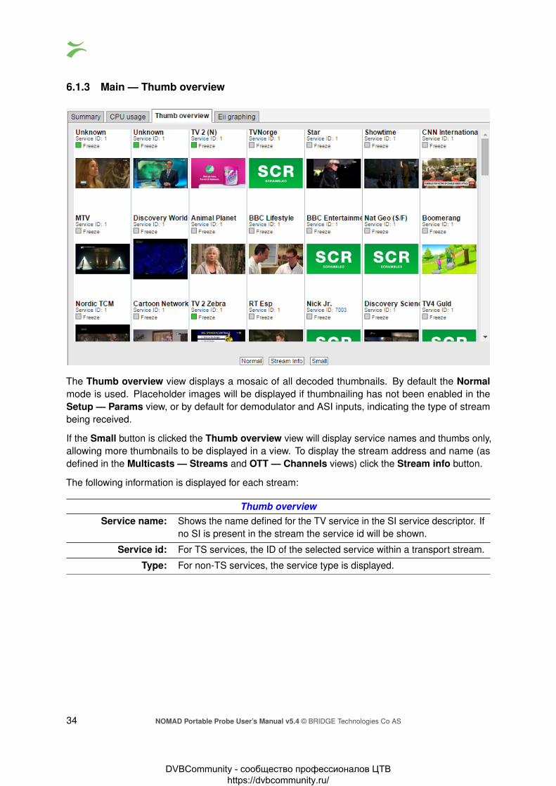
The Thumb overview view displays a mosaic of all decoded thumbnails. By default the Normalmode is used. Placeholder images will be displayed if thumbnailing has not been enabled in theSetup — Params view, or by default for demodulator and ASI inputs, indicating the type of streambeing received.
If the Small button is clicked the Thumb overview view will display service names and thumbs only,allowing more thumbnails to be displayed in a view. To display the stream address and name (asdefined in the Multicasts — Streams and OTT — Channels views) click the Stream info button.
The following information is displayed for each stream:
Thumb overviewService name: Shows the name defined for the TV service in the SI service descriptor. If
no SI is present in the stream the service id will be shown.
Service id: For TS services, the ID of the selected service within a transport stream.
Type: For non-TS services, the service type is displayed.
34 NOMAD Portable Probe User’s Manual v5.4 © BRIDGE Technologies Co AS
DVBCommunity - cообщество профессионалов ЦТВ https://dvbcommunity.ru/

Freeze-frame status: If the probe has been licensed with the Content Extraction and Alarmingoption, status bulbs are displayed indicating the current freeze-frame andcolor-freeze status for the streams.White: Unknown (typically due to the NOMAD being unable to decodevideo)Grey: freeze-frame detection is disabled.Green: freeze-frame detection is enabled, no freeze-frame is detected.Yellow: freeze-frame detection is enabled. Two consecutive equal frameshave been detected, but the freeze-frame error timeout value has notbeen exceeded.Red: freeze-frame is enabled. Freeze-frame has been detected and thefreeze-frame error timeout value has been exceeded, thus resulting in analarm.
The Thumbs Details pop-up view is accessed by clicking a thumb in the Thumb overview view.For more information about the details displayed in the Thumbs Details pop-up see chapter 6.4 formulticast streams, and chapter 6.3.2 for OTT channels. For demodulator and ASI inputs, thumbnailsare only decoded automatically if the Extract thumbnails option has been enabled in the associatedtuning setup, or if content check alarming (Content Extraction and Alarming option) has been enabledin the ETR threshold template. To decode the thumbnail manually, open the Thumbs Details view.Please note that initial extraction of thumbnails can take around one minute when decoding thethumbnail manually. The same pop-up details are displayed as when opened from the ETR 290 —Services view.
Clicking the Close button will close the view.
NOMAD Portable Probe User’s Manual v5.4 © BRIDGE Technologies Co AS 35
DVBCommunity - cообщество профессионалов ЦТВ https://dvbcommunity.ru/

6.1.4 Main — Eii graphing
Eii is short for External Integration Interface and constitutes a set of XML files accessible through theprobe web server interface for machine access to measurement data.
Portions of the Eii interface are available in this view for simple trend graphing over arbitrary long timeby the web browser.
The screenshot shows the bandwidth of two IP streams being graphed by sampling the Eii interfaceevery 2 seconds. The graph is stored in the client web browser for as long as the graph windowremains open. The graph starts again with zero history if the window is closed and then openedagain.
Up to 5 streams are possible to plot on the same graph using the dropdown menus named Stream Nto plot where N is 1 through to 5. The parameter to plot is selected through the dropdown calledParameter to plot. The following choices are available:
1. bitrate
2. rtp_drops
3. iat_avg
4. cc_errs
Refresh (seconds) selects how often samples are read and plotted on the graph.
Please refer to the separate Eii documentation on the customer area of the Bridge Technologieswebsite for more details.
36 NOMAD Portable Probe User’s Manual v5.4 © BRIDGE Technologies Co AS
DVBCommunity - cообщество профессионалов ЦТВ https://dvbcommunity.ru/

6.2 Alarms
OTT Channel
OTT Analysis
PID Thresholds
OTT Thresholds ETR Thresholds
FSM Settings
FSM Measurements
Alarm Settingsand Scheduling
SNMP Alarms Alarm Lists
System Events
ETH Thresholds
Service Thresholds Demodulator Thresholds
ETH Multicast
ETH Measurements
ASI/QAM/QPSK/COFDM Stream
ASI/QAM/QPSK/COFDM Measurements
Figure 6.1: Alarm handling in the NOMAD.
Figure 6.1 shows an overview of the alarm handling in the NOMAD. It is useful to obtain an under-standing of the alarm processing of the NOMAD – in particular how threshold settings and alarmsetup will affect alarm handling.
The NOMAD continuously compares measurement data with user defined thresholds in order togenerate alarms. These alarms are further checked against the settings defined in the Alarms —Alarm setup view, and the resulting alarms are presented in the alarm lists. These alarms will alsobe sent as SNMP traps to support third party management systems. Refer to Appendix: NOMADVersus VBC Alarms for a description of alarm handling in the VBC Controller.
The NOMAD distinguishes between events and alarms. The ETR software module will alwaysgenerate alarms and the Systems software module will always generate events. The Ethernetsoftware module will by default generate events for errors that are resolved within 1 second, otherwiseit will generate alarms. This can be overridden by checking the ‘Treat ethernet events as alarms’ boxin the Setup — Params view. The OTT module generates alarms only.
NOMAD Portable Probe User’s Manual v5.4 © BRIDGE Technologies Co AS 37
DVBCommunity - cообщество профессионалов ЦТВ https://dvbcommunity.ru/

6.2.1 Alarms — All Alarms
The Alarms view gives the user the possibility of viewing alarms according to type or as one combinedlist. The individual alarm lists can hold the number alarms indicated below independently of eachother, meaning that one may become full without affecting the other lists.
Alarm list capacity
Ethernet alarms (ETH) 400 alarms
Full Service Monitoring (FSM) 100 alarms
Over The Top Television (OTT) 100 alarms
ETSI TR 101 290 Analysis (ETR) 400 alarms
System alarms (SYS) 100 alarms
If Auto-refresh list is selected, the alarm list will be continuously updated with new alarms. Activealarms are always located at the top of the list.
Clicking the View list offline button gives the user the opportunity to view the complete alarms andevents list. By clicking one of the blue information icons leftmost in the offline list, a detailed alarmdescription can be viewed. The search field in the upper right corner of the view allows the userto type a text string and the alarm list is updated to display only streams and alarms matching thespecified text. To update the offline alarm list click the Auto-refresh list button and then go back tothe offline mode.
The alarm lists can be deleted by clicking the Flush alarms button. However it should be noted thatthis action will permanently clear the alarm lists — they cannot be restored.
The Export button enables export of the corresponding alarm list as an XML file. This file will open ina new window.
38 NOMAD Portable Probe User’s Manual v5.4 © BRIDGE Technologies Co AS
DVBCommunity - cообщество профессионалов ЦТВ https://dvbcommunity.ru/

6.2.2 Alarms — Alarm setup
The Alarm setup represents the final filtering stage for NOMAD alarms. The user selects whetheran alarm should be enabled or ignored, and associates an error severity level with each alarm, andassociates an error severity level with each alarm. When changes have been made to alarm settingsclick the Apply changes button for changes to take effect.
Figure 6.1 gives an overview of the total alarm handling of a NOMAD. The settings in the Alarmsetup view are represented by the Alarm Settings box in this figure.
Note that the probe alarm handling will also depend on the threshold template settings defined by theuser in the Multicasts — Ethernet thresh., ETR 290 — ETR thresh., ETR 290 — PID thresh., ETR290 — Service thresh., the RF thresholds for the different interface cards, and OTT — Thresholdsviews.
Also note that only enabled alarms are shown in the alarm lists and forwarded as SNMP traps.Enabling or disabling NOMAD alarms does however not affect the alarms presented by the VBC.Refer to Appendix: NOMAD Versus VBC Alarms for a description of the NOMAD versus VBC alarmhandling.
The following alarm severity levels may be selected:
OK: If enabled, the alarm will be present in the alarm list, color green
Warning: If enabled, the alarm will be present in the alarm list, color yellow
Error: If enabled, the alarm will be present in the alarm list, color orange
Major: If enabled, the alarm will be present in the alarm list, color red
Fatal: If enabled, the alarm will be present in the alarm list, color black
The following alarms and events are configured:
ETH (Ethernet) alarms
No signal: There has been no UDP packetfor the predefined period of time(default 1sec)
Default: Enabled,severity Major
FEC packet drop: One or more RTP packets couldnot be corrected by the FEC
Default: Enabled,severity Error
NOMAD Portable Probe User’s Manual v5.4 © BRIDGE Technologies Co AS 39
DVBCommunity - cообщество профессионалов ЦТВ https://dvbcommunity.ru/
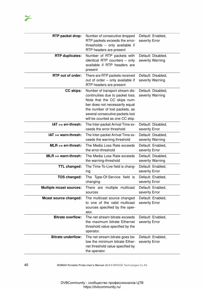
RTP packet drop: Number of consecutive droppedRTP packets exceeds the error-thresholds – only available ifRTP headers are present
Default: Enabled,severity Error
RTP duplicates: Number of RTP packets withidentical RTP counters – onlyavailable if RTP headers arepresent
Default: Disabled,severity Warning
RTP out of order: There are RTP packets receivedout of order – only available ifRTP headers are present
Default: Disabled,severity Warning
CC skips: Number of transport stream dis-continuities due to packet loss.Note that the CC skips num-ber does not necessarily equalthe number of lost packets, asseveral consecutive packets lostwill be counted as one CC skip.
Default: Disabled,severity Warning
IAT >= err-thresh: The Inter-packet Arrival Time ex-ceeds the error threshold
Default: Disabled,severity Error
IAT >= warn-thresh: The Inter-packet Arrival Time ex-ceeds the warning threshold
Default: Disabled,severity Warning
MLR >= err-thresh: The Media Loss Rate exceedsthe error-threshold
Default: Enabled,severity Error
MLR >= warn-thresh: The Media Loss Rate exceedsthe warning-threshold
Default: Disabled,severity Warning
TTL changed: The Time-To-Live field is chang-ing
Default: Enabled,severity Error
TOS changed: The Type-Of-Service field ischanging
Default: Enabled,severity Error
Multiple mcast sources: There are multiple multicastsources
Default: Enabled,severity Error
Mcast source changed: The multicast source changedto one of the valid multicastsources specified by the oper-ator.
Default: Enabled,severity Error
Bitrate overflow: The net stream bitrate exceedsthe maximum bitrate Ethernetthreshold value specified by theoperator.
Default: Enabled,severity Error
Bitrate underflow: The net stream bitrate goes be-low the minimum bitrate Ether-net threshold value specified bythe operator.
Default: Enabled,severity Error
40 NOMAD Portable Probe User’s Manual v5.4 © BRIDGE Technologies Co AS
DVBCommunity - cообщество профессионалов ЦТВ https://dvbcommunity.ru/

FSM alarmsFull service monitoring: No reply was obtained within
timeout period for the config-ured FSM service
Default: Enabled,severity Major
ETR (ETR 290) alarms
TS Sync: No TS Sync (no signal) Default: Enabled,severity Major
Sync byte: Sync byte error, sync byte not0x47
Default: Enabled,severity Major
PAT: Program Association Table error Default: Enabled,severity Major
Continuity: Continuity counter error Default: Enabled,severity Major
PMT: Program Map Table error Default: Enabled,severity Major
PID: PID is missing Default: Enabled,severity Major
Transport: Transport stream error indicatoris set
Default: Enabled,severity Major
CRC: Table checksum error Default: Enabled,severity Major
PCR: Program Clock Reference error Default: Enabled,severity Major
PCR Accuracy: Program Clock Reference accu-racy error (PCR jitter)
Default: Enabled,severity Major
PTS: Presentation Time Stamp error Default: Enabled,severity Major
CAT: Conditional Access Table error Default: Enabled,severity Major
NIT: Network Information Table error Default: Enabled,severity Major
SI Rep Rate: Wrong repetition rate for SI ta-bles
Default: Enabled,severity Major
Unref PID: PID is unreferenced Default: Enabled,severity Major
SDT: Service Description Table error Default: Enabled,severity Major
EIT: Event Information Table error Default: Enabled,severity Major
RST: Running Status Table error Default: Enabled,severity Major
NOMAD Portable Probe User’s Manual v5.4 © BRIDGE Technologies Co AS 41
DVBCommunity - cообщество профессионалов ЦТВ https://dvbcommunity.ru/

TDT: Time Date Table error Default: Enabled,severity Major
MGT: Master Guide Table error (ATSCmode)
Default: Enabled,severity Major
VCT: Virtual Channel Table error(ATSC mode)
Default: Enabled,severity Major
PIM/PNM: PIM/PNM error (ATSC mode) Default: Enabled,severity Major
RRT: Region Rating Table error(ATSC mode)
Default: Enabled,severity Major
ATSC EIT: ATSC EIT Table error (ATSCmode)
Default: Enabled,severity Major
STT: System Time Table error (ATSCmode)
Default: Enabled,severity Major
ETT: Extended Text Table error(ATSC mode)
Default: Enabled,severity Major
CA System: CA System error Default: Enabled,severity Major
PID min. bitr. PID minimum bitrate belowthreshold
Default: Enabled,severity Major
PID max. bitr. PID maximum bitrate exceedsthreshold
Default: Enabled,severity Major
PID checks: PID check error Default: Enabled,severity Major
Service min. bitr. Service minimum bitrate belowthreshold
Default: Enabled,severity Major
Service max. bitr. Service maximum bitrate ex-ceeds threshold
Default: Enabled,severity Major
Service checks: Service check error Default: Enabled,severity Major
MIP: Megaframe Insertion Packet er-ror
Default: Enabled,severity Major
Content: Content check error (checkingof audio and video)
Default: Enabled,severity Major
Reference: Reference check error (compar-ing the stream with a Gold TS)
Default: Enabled,severity Major
Gold TS: Error found while comparing thestream with the stored Gold TSsnapshot)
Default: Enabled,severity Major
Pre FEC BER: Bit error rate prior to Viterbi FECabove specified threshold (Ap-plicable for RF inputs)
Default: Enabled,severity Major
42 NOMAD Portable Probe User’s Manual v5.4 © BRIDGE Technologies Co AS
DVBCommunity - cообщество профессионалов ЦТВ https://dvbcommunity.ru/

Post FEC BER: Bit error rate after Viterbi FECabove specified threshold (Ap-plicable for RF inputs)
Default: Enabled,severity Major
MER: Modulation Error Ratio abovespecified threshold (Applicablefor RF inputs)
Default: Enabled,severity Major
SNR: Signal to Noise Ratio belowspecified threshold (Applicablefor RF inputs)
Default: Enabled,severity Major
Signal strength: Signal strength outside speci-fied thresholds (Applicable forRF inputs)
Default: Enabled,severity Major
SFN meas: Error with timing in DVB-T/T2SFN networks (ASI and DVB-T/DVB-T2 inputs)
Default: Enabled,severity Major
Packet error count: Detection of one or more pack-ets with errors after demodula-tor FEC (satellite input)
Default: Enabled,severity Major
Center frequency: Difference between receivedand configured RF frequencyexceeds specified threshold(Applicable for RF inputs)
Default: Enabled,severity Major
Symbol rate: Difference between receivedand configured symbol rate ex-ceeds specified threshold (Ap-plicable for RF inputs)
Default: Enabled,severity Major
Post BCH FER: DVB-T/T2 BCH Frame ErrorRate exceeds specified thresh-old (DVB-T mode)
Default: Enabled,severity Major
T2MI Errors in DVB-T2 Modulator In-terface protocol analysis
Default: Enabled,severity Major
LDPC LDPC iteration count higherthan threshold (DVB-T/DVB-T2)
Default: Enabled,severity Major
Eb/N0 Eb/N0 outside threshold (DVB-T/DVB-T2)
Default: Enabled,severity Major
EVM Error vector magnitude outsidethreshold (DVB-T/DVB-T2)
Default: Enabled,severity Major
Interface overflow: Input interface overflow error.Means that the probe is over-loaded and can not properly an-alyze the signals.
Default: Enabled,severity Major
SYS (System) events
NOMAD Portable Probe User’s Manual v5.4 © BRIDGE Technologies Co AS 43
DVBCommunity - cообщество профессионалов ЦТВ https://dvbcommunity.ru/

[Critical system errors]: Critical system errors prevent-ing the NOMAD from operatingcorrectly
Default: Enabled,severity ‘Fatal’
[System errors]: Enable this to view all systemerrors
Default: Enabled,severity ‘Major’
[System info]: Enable this to view system infor-mation messages such as timesynchronization
Default: Enabled,severity ‘OK’
OTT AlarmsThe number of profiles changed: The number of profiles flagged
in the manifest file changedDefault: Enabled,severity ‘Warning’
Profile stream type changed: The stream type of the profilechanged in the manifest
Default: Enabled,severity ‘Warning’
Minimum profiles The channel has less profilesthan specified in the threshold
Default: Enabled,severity Warning
Download bitrate low: The download duration time ex-ceeds the OTT bitrate threshold.The bitrate threshold is part ofthe OTT threshold template de-fined in the OTT — Thresholdsview. A threshold template is as-signed to a stream in the OTT— Channels view.
Default: Disabled,severity Warning
Download bitrate too low: The download duration time ex-ceeds the OTT chunk durationtime.
Default: Enabled,severity Error
Manifest size: The manifest file size exceedsthe OTT manifest size thresh-old.
Default: Enabled,severity Warning
Actual bitrate: The actual measured bitratedoes not match the profile bi-trate specified in the manifestfile.
Default: Enabled,severity Warning
Download timeout: The download time exceedstwice the chunk duration time.
Default: Enabled,severity Major
Address resolve error: Unable to resolve addressname
Default: Enabled,severity ‘Error’
Connection failed: Connection failed Default: Enabled,severity ‘Error’
Send error: Could not send data to host Default: Enabled,severity ‘Error’
Receive error: Could not receive data fromhost
Default: Enabled,severity ‘Major’
44 NOMAD Portable Probe User’s Manual v5.4 © BRIDGE Technologies Co AS
DVBCommunity - cообщество профессионалов ЦТВ https://dvbcommunity.ru/

Empty reply: Response did not contain anydata in body
Default: Enabled,severity ‘Major’
HTTP error: Invalid HTTP response Default: Enabled,severity ‘Major’
HTTP redirect error: HTTP 3xx redirection error Default: Enabled,severity ‘Major’
HTTP client error: HTTP 4xx client error Default: Enabled,severity ‘Major’
HTTP server error: HTTP 5xx server error Default: Enabled,severity ‘Major’
Static manifest: Manifest file unchanged forlonger than configured thresh-old.
Default: Enabled,severity Major
Manifest parse error: Failed to parse manifest file. In-valid format
Default: Enabled,severity ‘Major’
Unknown manifest: Cannot recognize manifest XMLformat
Default: Enabled,severity ‘Fatal’
6.2.3 Alarms — Flash Alarms (FLASH option)
The FLASH option enables the Flash alarms tab. This alarm list contains the last 20,000 alarms andkeeps them in non-volatile memory so that they survive reboots and power-outages. This opens up alot of possibilities for probes that cannot be reached while doing measurements and for probes thatneed to be powered down and consulted elsewhere. It also severely increases the size of the alarmlist allowing browsing of older alarms.
NOMAD Portable Probe User’s Manual v5.4 © BRIDGE Technologies Co AS 45
DVBCommunity - cообщество профессионалов ЦТВ https://dvbcommunity.ru/

6.3 OTT
6.3.1 OTT — Active testing
The OTT option enables monitoring of up to 250 OTT channels. Up to 25 OTT engines (depends onlicense) can operate in parallel, and each engine licensed allows any channels to be analyzed. Eachengine analyses channels in series and can be configured with any number of channels up to themaximum allowed by the license.
The NOMAD will parse a channel’s manifest file, and for a live channel one of the latest chunks ineach OTT profile’s chunk sequence will be analyzed. The engine then moves on to the next OTTchannel in the channel list defined by the user. For a VoD channel the OTT engine will analyze allchunks in the VoD file, one in each round-robin loop.
If manifest file parsing or chunk analysis reveals an error, an alarm will be raised. Note that somealarms depend on user defined threshold values. Alarms must also be enabled in the Alarm —Alarm setup view.
Thumbnail decoding is available for non-encrypted HLS, HDS, DASH and RTMP channels, as wellas some types of encrypted HLS channels.
The following OTT information is displayed in the Active testing view:
46 NOMAD Portable Probe User’s Manual v5.4 © BRIDGE Technologies Co AS
DVBCommunity - cообщество профессионалов ЦТВ https://dvbcommunity.ru/

Status bulb: A bulb indicates the current status of the channel, i.e. the most severeprofile status.
Thumb: If the selected channel is of type HLS, HDS, DASH or RTMP a thumbnailof the content will be decoded and updated. Thumbnail decoding is aprocess asynchronous of the channel analysis and therefor should notbe expected to be updated at the same time. The main purpose of thethumbnails is to provide brief information about the channel contents.
Channel: The channel name defined by the user and linked to a URL in the OTT— Channels view.
Progress: Channels will be analyzed sequentially, and the progress bar showswhich channel is currently being monitored and how analysis is pro-gressing.
Alarm history: A bar graph showing alarm severity history. It can either show thelast 120 minutes or the last 24 hours. To switch between them, pressthe “24h” or “2h” button on the left under the channel list. Each barcolor represents the alarm severity level as configured under Alarms —Alarm setup.
Current profile status: The channel health bar displays the current status for individual channelprofiles. Profiles are separated by vertical black lines.Colors indicate profile alarm status:
• Green: OK• Yellow: Warning• Orange: Error• Red: Major• Black: Fatal
Profiles: The number of profiles associated with a channel.
Encryption: Scrambling information is resolved from the profile manifest. If theprofile is scrambled the encryption field will read Yes. If the profile istransmitted in clear the encryption field will read No.
Profile info: Channel and profile information is resolved from the manifest files. Atchannel level the OTT format is displayed (Smoothstream, HLS, AdobeHDS, MPEG DASH or SHOUTcast). At profile level the profile bitrate isdisplayed.
Engine: Indicates which OTT engine is assigned to what channel. The NOMADcan be licensed with anywhere from 1 up to 25 OTT engines. Eachengine is capable of handling any number of channels.
6.3.2 OTT — Details
Click the blue information button on a channel to open the details window. This window providesdetailed information about the status and alarms on all the profiles for the selected channel. Thesame pop-up can be opened from the Main — Thumb Overview view, see chapter 6.1.3 for moreinformation.
NOMAD Portable Probe User’s Manual v5.4 © BRIDGE Technologies Co AS 47
DVBCommunity - cообщество профессионалов ЦТВ https://dvbcommunity.ru/

6.3.2.1 OTT — Details — Profiles
The Profiles view in this pop-up consists of two tables detailed below:
The following information relevant for the overall OTT channel is shown in the first part of the Details— Profiles pop-up window:
Channel: The channel name defined by the user and linked to a URL in the OTT —Channels view. A bulb indicates the current status of the channel, i.e. the mostsevere profile status.
Progress: Channels will be analyzed sequentially, and the progress bar shows whichchannel is currently being monitored and how analysis is progressing.
Profiles: The number of profiles associated with a channel.
Profile status: The channel health bar displays the current status for individual channel profiles.Profiles are separated by vertical black lines.Colors indicate profile alarm status:
• Green: OK• Yellow: Warning• Orange: Error• Red: Major• Black: Fatal
Stream type: Channel and profile information is resolved from the manifest files. At channellevel the OTT format is displayed (Smoothstream, HLS, Adobe HDS, MPEGDASH or SHOUTcast).
48 NOMAD Portable Probe User’s Manual v5.4 © BRIDGE Technologies Co AS
DVBCommunity - cообщество профессионалов ЦТВ https://dvbcommunity.ru/

In the same view below the table for the overall channel a more detailed view per channel profile isshown with the following information in it:
Profile: The name of the OTT profile as flagged in the manifest files.
Type: Live for live content or VoD for stored content. The distinction between the twois done based on whether the profile sequence numbers update or not.
Profile health: A timeline graph display of a combined bitrate and alarm representation forindividual profiles. Refer to Appendix C for a description of these graphs. Thetimeline duration is either 2 or 24 hours, and the graph resolution is one minutefor the 2 hour graph, and twelve minutes for the 24 hour graph.
Profile bps: The profile nominal bandwidth as flagged in the manifest files.
Actual bps: The actual profile bitrate, i.e. the chunk size (megabits) divided by the chunklength (seconds). The actual profile bitrate should match the manifest bitratespecification within limits defined by the user in the OTT thresholds templateassociated with a channel. Otherwise an alarm will be raised.
Download bps: The download bitrate, i.e. the chunk size (megabits) divided by the downloadtime (seconds).
Chunk length: The profile chunk length (seconds) specified in the manifest file.
Download time: The actual profile chunk download time (seconds).
Download size: The actual profile chunk size (bytes).
Encrypt.: Yes or No depending on whether the content for that profile is encrypted ornot.
HTTP header: The current HTTP header of the last chunk downloaded for that profile.
NOMAD Portable Probe User’s Manual v5.4 © BRIDGE Technologies Co AS 49
DVBCommunity - cообщество профессионалов ЦТВ https://dvbcommunity.ru/

6.3.2.2 OTT — Details — Manifest
The Manifest view shows health information on the overall manifest file for the channel as well as forthe manifest files for the individual profiles.
Channel: The channel name defined by the user and linked to a URL in the OTT —Channels view. A bulb indicates the current status of the channel, i.e. the mostsevere profile status.
Progress: Channels will be analyzed sequentially, and the progress bar shows whichchannel is currently being monitored and how analysis is progressing.
Profiles: The number of profiles associated with a channel.
Profile status: The channel health bar displays the current status for individual channel profiles.Profiles are separated by vertical black lines.Colors indicate profile alarm status:
• Green: OK• Yellow: Warning• Orange: Error• Red: Major• Black: Fatal
Profile info: The type of stream is shown here. Apple HLS, Microsoft Smoothstream, AdobeHDS, MPEG DASH or SHOUTcast.
Manifest size: The size in bytes of the main/top manifest file for the overall channel.
Manifest file: Clickable URL for displaying the manifest file as text for the overall channel.
50 NOMAD Portable Probe User’s Manual v5.4 © BRIDGE Technologies Co AS
DVBCommunity - cообщество профессионалов ЦТВ https://dvbcommunity.ru/

Manifest URL: A clickable link to the current main/top manifest file for the overall channel.
HTTP header: The current HTTP header of the main/top manifest file for the overall channel.
Just below the channel manifest information in the same window is the detailed manifest informationper profile. This view contains the following information:
Profile: The name of the OTT profile as flagged in the manifest files.
Profile bps: The profile nominal bandwidth as flagged in the manifest files.
Type: Live for live content or VoD for stored content. The distinction between the twois done based on the contents of the manifest file.
Seq.age: The profile sequence shows how long it has been since the manifest was updatedin whole seconds.
Manifest size: The size in bytes of the manifest file for a particular profile.
Manifest file: Clickable URL for displaying the manifest file as text for this particular profile.
Manifest URL: Clickable URL to the profile manifest file.
HTTP header: URL to HTTP header in text form for a particular profile manifest file.
NOMAD Portable Probe User’s Manual v5.4 © BRIDGE Technologies Co AS 51
DVBCommunity - cообщество профессионалов ЦТВ https://dvbcommunity.ru/

6.3.2.3 OTT — Details — Alarms
The Details — Alarms view gives an at-a-glance overview of any active OTT alarms for the selectedchannel. An alarm log for the selected channel is also provided here.
In the right corner of the pop-up window is a free text search field used to narrow down the entries inthe alarm log.
The alarms are the same ones as explained for the Alarms — Alarm setup view, see chapter 6.2.2for more information.
52 NOMAD Portable Probe User’s Manual v5.4 © BRIDGE Technologies Co AS
DVBCommunity - cообщество профессионалов ЦТВ https://dvbcommunity.ru/

6.3.2.4 OTT — Details — Thumbnails
The Thumbnails tab will provide information about the current thumbnails in the channel.
The quality of the content in the selected profile can be viewed in the thumbnail section, and the usermay alter the selected profile in the drop down list.
The section on the right hand side provides specific decoder and chunk information.
By pressing the Apply button without selecting a profile from the drop-down list the thumbnail willbe switched to the default selection; Auto select. Auto select will select the profile with the highestbitrate and video data.
Decoder informationSize: The video picture size of the selected profile
Aspect ratio: The video aspect ratio of the selected profile
Pixel aspect ratio: The video pixel aspect ratio of the selected profile
Codec: The video encoding format of the selected profile
Quality: The video sampling format of the selected profile
Frame rate: The video frame rate of the selected profile (Hz)
Chunk InformationEngine ID: The OTT engine monitoring the selected channel.
Channel ID: The ID of selected channel corresponding to the list of channels defined bythe user.
NOMAD Portable Probe User’s Manual v5.4 © BRIDGE Technologies Co AS 53
DVBCommunity - cообщество профессионалов ЦТВ https://dvbcommunity.ru/

Profile ID: The ID of the selected profile.
Bitrate: Bitrate rate of the a chunk.Streamtype: The type of the stream detected; live or video on demand.
Sequence Number: The sequence number of a chunk.
6.3.2.5 OTT — Details — Alignment
The Alignment tab gives the user a view of all the profiles for a selected channel with thumbnails andcorresponding data.
Profile Alignment Information
Profile: This is a generated ID that identifies the OTT profile. The firstprofile listed is always the one with the highest signaled bitrate.
Chunk/Sequence Number: The chunk or sequence number for the current thumbnail. This iseither signaled in the stream, or generated by the NOMAD.If the sequence numbers are highlighted in yellow, the thumbnailsare not generated from the same chunk for all profiles, and maytherefor appear to be out of synchronization.
Bitrate: The signaled bitrate for this profile (bits/s).
Size & FPS: Indicates the original video size (pixels) and the frame-rate (Hz).
Audio: Indicates the audio channel layout.
54 NOMAD Portable Probe User’s Manual v5.4 © BRIDGE Technologies Co AS
DVBCommunity - cообщество профессионалов ЦТВ https://dvbcommunity.ru/

6.3.3 OTT — Latency
The OTT Channel Latency Distribution feature makes it possible to measure the delay from when achunk is available through different caches, compared to its origin.
Before using this feature, you must set aside a number of OTT engines to exclusively measure thetimings of one channel on one server. This is done in the OTT — Settings view. In general, youwould need to use two Latency Engines per channel: one for the origin and one for the cache.
After selecting the number of Latency Engines, open the OTT — Channels view and add the channelfrom multiple sources (URLs), using the same base name, but different classes, e.g. TV1@Originand TV1@CDN. Then set the Measurement mode to Latency if you are only interested in thetimings from this server, or Both if you also want the traditional Active Testing measurements. Eachadded channel will use one dedicated Latency Engine, if you try setting Latency or Both and thereis no free Latency Engine available, it will default back to Normal.
Once the configuration is finished, you are ready to use this feature. Select the channel to produce alatency graph for using the Channel drop-down. Then select which of the classes of the channel thatis to be used as the reference in the Reference drop-down. This is used to calculate the time deltadifference.
The graph will start off showing the difference in availability time of each chunk for the last minuteand will build up history until displaying the last hour. Due to the nature of timing in different engines,these measurements are accurate down to ±0.5 seconds. To minimize these inaccuracies, a movingaverage is provided, smoothing the spikes. The sliding window can be manually controlled by movingthe Avg window slider. It is also possible to display the minimum and maximum values by checkingthe Show min/max checkbox.
NOMAD Portable Probe User’s Manual v5.4 © BRIDGE Technologies Co AS 55
DVBCommunity - cообщество профессионалов ЦТВ https://dvbcommunity.ru/

6.3.4 OTT — Channels
The OTT Channel Configuration list shows OTT channels configured by the user.
To add a channel to the list click the Add new channel button. This will open the Edit channelpop-up view, allowing the user to define channel parameters. A channel entry can be selectedby clicking the channel; the list entry will be highlighted. Several list entries can be selected byusing regular Ctrl + click functionality. Clicking the Duplicate selected button will open the Editchannel pop-up view with all channel parameters duplicated, except the channel name. ClickingDelete selected will delete the highlighted list entry. Clicking Distribute selected will distribute theselected channels across the licensed OTT engines (the NOMAD can be licensed with up to 25OTT engines). Clicking Edit selected will open the Edit channel pop-up view associated with thehighlighted channel. Batch editing is supported; this is convenient if a new threshold template shouldbe assigned to a number of channels or if monitoring of several channels should be enabled ordisabled. Select the channels and click the Edit selected button. Parameters differing betweenchannels will be indicated in the Edit selected pop-up view by an asterisk wildcard symbol.
The search field in the upper right corner of the view allows the user to type a text string, and theOTT channel list is updated to display only channels matching the specified text.
GeneralEnabled: Check the ‘Enabled’ check box to start monitoring the OTT
service.
56 NOMAD Portable Probe User’s Manual v5.4 © BRIDGE Technologies Co AS
DVBCommunity - cообщество профессионалов ЦТВ https://dvbcommunity.ru/

Select engine: A number between 1 and 25, depending on license activated,indicating which OTT engine the channel uses.
Threshold: The OTT threshold that should be assigned to the OTT chan-nel. OTT thresholds that have been defined in the OTT —Thresholds view are available for selection from the drop-down menu.
VBC thresholds: The alarm threshold template used to configure when alarmsare generated towards the VBC server.
Measurement mode Specify if you want Normal active testing measurements,OTT Channel Distribution Latency measurements, or Bothkinds of measurements for this channel.Each channel you set to either Latency or Both uses up oneLatency Engine. If you do not have any spare, it will be setback to Normal. See OTT — Latency for more info.
Name: A name should be assigned to each OTT channel. The namewill be used throughout the NOMAD’s user interface whenreferring to this channel.
Manifest URL: The URL of the OTT channel.Player URL: In this field you can enter the URL to a web page which will
open the OTT channel in your browser. If entered, a ‘play’button will be displayed in the OTT overview tab, which willopen the selected URL in a new browser tab.
Smooth Streaming target chunk For Smooth Streaming, this specifies which chunk, countedfrom the bottom of the list, the NOMAD should downloadwhen doing active testing on a live channel. For other formats,this option is ignored.
VCAS hostname If this channel is encrypted using a Verimatrix VCAS 3.7server, entering the IP address or hostname of the VCASserver’s encoder interface will allow descrambling of the en-crypted chunks. See OTT descrambling with Verimatrixfor more info.
Availability mode If this option is enabled, the engine will only check for chunkpresence but not download the entire file. This also disablesthumbnail generation.
RTMP: Check this check box if the channel is an RTMP channel.RTMP live: Check this check box if the RTMP channel is a live service.
Thumbnail: If the thumbnail option is enabled thumbnails will be availablefor the selected channels in the Active testing and Thumb-nails sections.
Alignment: If the alignment option is enabled the alignment section willbe available.
NOMAD Portable Probe User’s Manual v5.4 © BRIDGE Technologies Co AS 57
DVBCommunity - cообщество профессионалов ЦТВ https://dvbcommunity.ru/

Adv. manifestEnable adv. settings: Check this box to enable the advanced manifest settings. If unchecked,
all settings on this page are ignored.
Method: Determines which HTTP method to use when requesting the top-levelmanifest file. Supported methods are GET and POST.
Content-Type: When requesting the manifest using the HTTP POST, use this Content-Type for the submitted request body.
Additional headers: To provide additional custom request headers or overwrite the defaultheaders when requesting the top-level manifest file, create a text filecontaining the headers and upload them here.
Body: When requesting the manifest using the HTTP POST, upload the file tosubmit here.
The advanced manifest options can be used in instances where the master manifest file is not directlyavailable to download. If your channel needs several steps of authentication or other web servicecalls before supplying clients with an URL to the master manifest, you can make an “in-between” webservice which the NOMAD sends all required info to do the authentication and/or channel lookupsthrough this interface, and which returns an JSON file with an “url” parameter containing the URL tothe master manifest file.
6.3.5 OTT — Settings
58 NOMAD Portable Probe User’s Manual v5.4 © BRIDGE Technologies Co AS
DVBCommunity - cообщество профессионалов ЦТВ https://dvbcommunity.ru/

The Settings tab makes it possible to change OTT global monitoring parameters. Press Apply toconfirm changes made.
Settings
Round time: Sets the minimum round time of all of the OTT engines, in seconds(default: 15 seconds). If an engine finishes processing all its chan-nels in less time than this, it waits until this amount of seconds haspassed since it started the round before starting to process throughits channels again.Note: The round time may not be set to any value less than 2 second.
Reset connection after: Configures the NOMAD OTT engines to reset the connections afterthe specified number of minutes. This is useful for cases where theserver has a limit for how long a session can live. By resetting beforethat limit a new session is created and the problem is avoided.
Latency engines: Select the number of engines to dedicate to OTT latency monitoring.These engines will not be available for regular OTT monitoring, andthe value must be less than the total number of licensed OTT engineson the probe (up to 25 for the NOMAD). See OTT — Latency for moreinfo.
6.3.6 OTT — Thresholds
The OTT Threshold presets list shows OTT threshold templates configured by the user.
To add a threshold template to the list click the Add new threshold button. This will open the Editthreshold pop-up view, allowing the user to define threshold parameters. A threshold template entrycan be selected by clicking the threshold template; the list entry will be highlighted. Several list entriescan be selected by using regular Ctrl + click functionality. Clicking the Duplicate selected buttonwill open the Edit threshold pop-up view with all threshold template parameters duplicated, exceptthe threshold template name. Clicking Delete selected will delete the highlighted list entry. ClickingEdit selected will open the Edit threshold pop-up view associated with the highlighted thresholdtemplate. Batch editing is supported. Select the threshold templates and click the Edit selectedbutton. Parameters differing between templates will be indicated in the Edit selected pop-up view byan asterisk wildcard symbol.
The search field in the upper right corner of the view allows the user to type a text string, and thethreshold list is updated to display only thresholds matching the specified text.
NOMAD Portable Probe User’s Manual v5.4 © BRIDGE Technologies Co AS 59
DVBCommunity - cообщество профессионалов ЦТВ https://dvbcommunity.ru/

To disable a threshold alarm, set the threshold value to –1. This does not apply for Manifest XMLsize.
Threshold preset
Name: The threshold template name defined by the user.
Refs: The number of channels associated with the threshold template
Download speed error: The maximum allowed difference between profile bitrate and downloadbitrate (%). If the difference exceeds the threshold value a bitrate erroralarm will be raised.
Download speed warn: The maximum allowed difference between profile bitrate and downloadbitrate (%). If the difference exceeds the threshold value a bitrate errorwarning will be raised.
Actual bitrate min: The minimum allowed bitrate when measured actual bitrate is com-pared to profile bitrate (%). If the actual bitrate goes below the thresholdan actual bitrate alarm will be raised.
Actual bitrate max: The maximum allowed bitrate when measured actual bitrate is com-pared to profile bitrate (%). If the actual bitrate exceeds the thresholdan actual bitrate alarm will be raised.
Sequence age: The maximum time a manifest can remain unchanged before a manifestage alarm is raised.
Manifest XML size: The maximum detected size of the manifest before a manifest sizealarm is raised.
Min. profiles: Minimum number of profiles in the selected channel before an alarm israised.
60 NOMAD Portable Probe User’s Manual v5.4 © BRIDGE Technologies Co AS
DVBCommunity - cообщество профессионалов ЦТВ https://dvbcommunity.ru/

6.4 Multicasts
6.4.1 Multicasts — Parameters
The Multicasts — Parameters view displays detailed information about each stream.
The user selects which group of measurements should be displayed. Selections are IP parameters, TSparameters, Ethernet parameters, RTP and FEC parameters, User-defined parameters and Statisticalparameters. If User-defined parameters is selected, the Multicasts view displays parameters selectedby the user in the Multicasts — Parameters — Fields view.
For each page the Accumulated row at the bottom of the multicast list displays accumulated valuesfor all streams associated with the page. The accumulated Min bitrate and Max bitrate is the minimumand maximum value of the Accumulated current bitrate.
When the Current page button is clicked it is possible to select the page from a drop-down menu.The associated thumbnails are shown in the leftmost column of the list of measurements. Click oneof the small thumbnails to view a larger thumbnail that is updated more frequently. Note that it ispossible to disable probe thumbnail extraction in the Setup — Params view.
When All streams (offline) is clicked a complete list of measurements for all joined streams isdisplayed. A search field allows the user to type a text string and the multicast list is updated todisplay only multicasts matching the specified text. Note that monitoring parameters and thumbs willnot be updated in All streams (offline) mode.
NOMAD Portable Probe User’s Manual v5.4 © BRIDGE Technologies Co AS 61
DVBCommunity - cообщество профессионалов ЦТВ https://dvbcommunity.ru/

Peak and aggregate measurements are cleared when the Clear counters or Clear counters allpages button is clicked.
Clicking the Export button will allow export of the measurement data as an XML file that is opened ina new window.
Click the Trim ch-list button to unjoin streams with current status ‘No signal’, thereby removing themfrom the list. The Statistical parameters view lists sum or peak values for parameters over theinterval indicated by the selected time button (Last 4d, Last 24h, Last 8h, Last 20m, Last 1m).
Clicking a stream brings up the Detailed monitoring pop-up described later in this section.
In All streams (offline) mode a search field allows the user to type a text string and the multicast listis updated to display only multicasts matching the specified text.
62 NOMAD Portable Probe User’s Manual v5.4 © BRIDGE Technologies Co AS
DVBCommunity - cообщество профессионалов ЦТВ https://dvbcommunity.ru/

Joined multicastsi©: Click the information icon to access the Detailed Monitoring pop-up view.
Thumb: A thumbnail is displayed for each stream. Click the small thumbnail to view alarger image that is updated more frequently.
Name: The stream name specified by the user in the Edit Multicast view
Signal: Time since last signal loss
Page: The page associated with the multicast
Mapping: For MPEG-2 Transport streams, the number of MPEG-2 packets mapped intoeach RTP or UDP packet is displayed here. For SMPTE 2022-6 SDI over IPstreams, “SDI/RTP” is displayed, and for other unsupported RTP streams, “RTPdata” is displayed.
Net bitrate: Instantaneous MPEG-2 Transport Stream bitrate excluding null packets (PID8191). The instantaneous bitrate is measured over a time period of 1000 ms.
CC errs: The number of times a discontinuity has been detected for all the MPEG-2 Trans-port Stream continuity counters. This value is the total number of discontinuitiesdetected for all PIDs present. Note that this value does NOT represent thenumber of MPEG-2 TS packets lost because any continuity counter mismatchdetected for an IP-frame will increase CC errs by one. CC errors are serious asthey will in practice usually result in visual video artifacts (‘blocking’) if occurringon the video PIDs. CC errors can be due to an erroneous input signal to thestreaming head-end (e.g. from satellite rain fading or changes in the uplink).Alternatively, CC errors can arise from IP packets being dropped in the network.
PIDs: Number of PIDs in the MPEG2-TSSyncb errs: Number of transport stream packets with wrong syncbyte (0x47)
Curr bitrate: Instantaneous MPEG-2 Transport Stream bitrate including null packets (PID8191). The instantaneous bitrate is measured over a time period of 1000 ms.For non-TS traffic the bitrate is calculated from the size of the UDP payloads.
Min bitrate: The minimum current bitrate measurementMax bitrate: The maximum current bitrate measurementIP packets: The number of IP packets received
Dst address: Multicast/unicast destination address : port
TOS: Type-Of-Service (also called Differentiated Services Field)
TTL: Time-To-LiveVLAN ID: Native VLAN ID of this stream
Src address: Multicast/unicast source address : port
Joined src: The source address of the originally joined multicast.
IAT avg: Average Inter-Arrival Time. The average time between consecutive IP frames(in milliseconds). Recalculated each second.
IAT min: The Minimum Inter-Arrival Time is the minimum registered time between twoconsecutive IP frames carrying video. Units are in milliseconds.
NOMAD Portable Probe User’s Manual v5.4 © BRIDGE Technologies Co AS 63
DVBCommunity - cообщество профессионалов ЦТВ https://dvbcommunity.ru/

IAT max: The Maximum Inter-Arrival Time is the maximum registered time between twoconsecutive IP frames carrying video. Units are in milliseconds. The Max-IAT isa measure of the maximum amount of network-induced packet jitter present. IPpacket jitter affects video quality and should be minimized.
Src MAC: Source MAC addressDst MAC: Destination MAC address
RTP drops: Accumulated number of dropped IP-frames due to network errors. Only availablefor multicasts that carry RTP information. When running video inside an RTPwrapper it is possible to exactly deduce the number of dropped IP frames dueto network issues. This is possible as a result of the 16-bit sequence counterinside the RTP header. The following sequence will generate an RTP drops of+3: . . . , 10, 11, 12, 16, 17, 18, . . .
RTP dups: Accumulated number of duplicate IP-frames. Only available for multicasts thatcarry RTP information. Duplicate IP-frames in the network can occur undernormal circumstances and does not necessarily indicate network problems. Thefollowing sequence will generate an RTP dups of +2: . . . , 10, 11, 12, 12, 12, 13,14, . . .
RTP ooo: Accumulated number of times a packet has been found to be out of order. Onlyavailable for multicasts that carry RTP information. An out-of-order situation isdefined to have occurred when the current sequence number is lower than theprevious one. The following sequence will generate an RTP ooo of +2 (sincethere are two occurrences): . . . , 10, 11, 15, 12, 16, 17, 13, 14, 18, 19, . . .
RTP lag: The maximum number of packet positions an out-of-order packet has beenmoved relative to its correct position. So for example 1,2,3,5,6,7,8,4,9,10 willresult in an RTP lag of 4. The RTP lag is a good measure of how big a packetre-ordering buffer is needed in the receiving equipment to re-order packets.
Min hole size: Minimum number of consecutive dropped RTP packets. The sequence1,2,3,10,11,12,15 gives a min hole size of 2.
Max hole size: Maximum number of consecutive dropped RTP packets. The sequence1,2,3,10,11,12,15 gives a max hole size of 6.
Min hole sep: Minimum number of RTP packets separating any holes. The sequence1,2,3,10,11,12,15 gives a min hole sep of 3.
Num holes: Number of packet loss sequences. The sequence 1,2,3,10,11,12,15 gives anum holes of 2.
FEC mode: The CoP3 FEC modeFEC drops: Number of RTP packet drops in the main stream that the FEC could not correct
C-FEC drops: Number of IP packets in the column-FEC streams dropped
R-FEC drops: Number of IP packets in the row-FEC streams dropped
Statistical parameters
MPEG-2 transport stream parameters
i©: Click the information icon to access the Detailed Monitoring pop-up view.
64 NOMAD Portable Probe User’s Manual v5.4 © BRIDGE Technologies Co AS
DVBCommunity - cообщество профессионалов ЦТВ https://dvbcommunity.ru/

Name: The stream name specified by the user in the Edit Multicast view
ES(IAT): Number of seconds during selected period with Inter-packet Arrival Time higherthan associated Ethernet IAT warning threshold
ES(MLR): Number of seconds during selected period with Media Loss (corresponding tonumber of seconds with CC-errors)
ES(RTP): Number of seconds during selected period with RTP packet drops
ES(overfl): Number of seconds during selected period with bitrate overflow
ES(nosig): Number of seconds during selected period without signal
Peak(IAT): Peak Inter-packet Arrival Time during selected period.
Sum(MLR): Sum of Media Loss during selected period (equals number of TS packets lost)
Peak(bitr): Peak stream bitrate during selected period
Thumbnails
The probe will try to generate thumbnail pictures for all streams. For multi-program transport streams(MPTS) the first video component is selected. MPEG-2, H.264/MPEG-4, H.265/HEVC and JPEG 2000video formats in standard definition, high definition or ultra-high definition are supported in MPEG-2transport streams, as well as SMPTE 2022-6 uncompressed video in RTP streams.
The thumbnail update rate will depend on how the streams are coded and if they are standarddefinition, high definition or ultra-high definition. It is possible to increase the update rate by openingthe Thumb View pop-up, described below.
If the probe is unable to generate a thumbnail from the signal, it will present one of the following icons:
Shown if no data is received for the stream. There should be a match betweenpresenting this icon and a No-signal alarm; however since the alarm and thumbnailmechanisms work independently of each other they have been given different names(loss of signal and no signal).
Shown while the thumbnail engine is trying to decode a thumbnail picture and moreprecise status information has not yet been obtained. This icon is typically displayedafter probe reboot or if new streams have recently been joined.
Shown if the service does not carry a video PID — which is the case for radio services.
The stream contains no service, as signaled in PSI/SI.
The signal cannot be decoded due to excessive CC errors or RTP packet drops.
The probe does not support thumbnail generation for this protocol mapping.
The signal is recognized as being MPEG-2 encoded but the thumbnail extractor isunable to correctly decode a thumbnail picture.
The signal is recognized as being MPEG-4/H.264 encoded but the thumbnail extractoris unable to correctly decode a thumbnail picture.
NOMAD Portable Probe User’s Manual v5.4 © BRIDGE Technologies Co AS 65
DVBCommunity - cообщество профессионалов ЦТВ https://dvbcommunity.ru/

The signal is recognized as being MPEG-H/H.265 encoded but the thumbnail extractoris unable to correctly decode a thumbnail picture.
The signal is recognized as being JPEG 2000 encoded but the thumbnail extractor isunable to correctly decode a thumbnail picture.
The signal is recognized as being an uncompressed (raw) video stream but thethumbnail extractor is unable to correctly decode a thumbnail picture.
This icon is shown if the probe is unable to receive or analyze the PMT PID. Onlystreams with PSI information can have thumbnails decoded since the probe does notsupport a manual specification of the video PID.
The probe can only generate a thumbnail picture if the video data is not scrambled.
Detailed Monitoring
The Detailed Monitoring pop-up is activated by clicking a stream line in the monitoring list.
The NOMAD is continuously gathering detailed information for the selected multicast. The NOMADwill continue updating the detailed information for the selected multicast until another is selected.Clicking the Clear button will clear all information about the selected stream, including PSI/SI analysisdata.
The Detailed Monitoring — Services view lists detected MPEG-2 TS services (by analyzing thePSI/SI tables) or SMPTE 2022-6 SDI over IP components, providing the following aggregate informa-tion for each service:
Service/Pid: For each service, the service-name or service-id is obtained from thePSI/SI tables. PIDs that do not belong to a service are denoted ‘OtherPIDs’. The service ID is presented in square brackets.
66 NOMAD Portable Probe User’s Manual v5.4 © BRIDGE Technologies Co AS
DVBCommunity - cообщество профессионалов ЦТВ https://dvbcommunity.ru/

Service/Component: This replaces the “Service/Pid” column for SMPTE 2022-6 SDI over IPstreams, displaying the identified components.
Bitrate: Service or component bitrate in bits per second
Min bitr.: Minimum service or component bitrate in bits per second
Max bitr.: Maximum service or component bitrate in bits per second
CC errors: Number of Continuity Counter occurrences
Thumb: Click the i© icon to access the Thumb pop-up view, explained below
Type: The list entry service type or PID type
PCR: This field will be checked if the corresponding PID carries PCR
Scr: This field will be checked if the corresponding PID is scrambled
Directly beneath this list, the current parameters for the selected stream are displayed, as in theJoined multicasts list.
In the Detailed Monitoring — IAT view the Inter Arrival Time histogram shows the accumulatednumber of IAT measurements within each presented interval. Vertical green lines indicate themaximum and minimum IAT values. By clicking the IAT range buttons it is possible to change thezooming of the graph. If the IAT auto button is pressed the diagram will auto-scale to always includethe minimum and maximum IAT readings.
The IAT histogram is a very useful and intuitive measure of how well the network is performing interms of forwarding real-time traffic. A predictable and tightly bunched graph indicates small levels ofnetwork jitter. An unbound graph indicates network jitter issues typically brought forward by trafficcongestion or misconfigured routers. Clicking the Clear IAT button will clear the IAT graph.
Under the IAT histogram the Multicasts — Parameters (Current parameters) measurements forthe selected stream are displayed. Clicking the Clear button will clear all information about theselected stream, including PSI/SI analysis data.
Clicking the MediaWindow button will open the Media Window Selected channel view. This isdescribed in section 6.5.
NOMAD Portable Probe User’s Manual v5.4 © BRIDGE Technologies Co AS 67
DVBCommunity - cообщество профессионалов ЦТВ https://dvbcommunity.ru/

Note that for variable bitrate streams the IAT histogram will show a very different IAT distributioncompared to the histogram for a constant bitrate stream. The histogram in the screenshot abovedisplays the IAT distribution for a CBR stream.
Thumb View
The Thumb View pop-up is accessed by clicking an information icon in the Detailed Monitoring —Services view. This view presents a large thumbnail, as well as video and audio metadata for theselected stream, with an increased update rate compared to non-selected streams. Service audiolevel is indicated by one audio level bar per audio component. The same pop-up can be opened fromthe Main — Thumb Overview view, see chapter 6.1.3 for more information.
Clicking the Close button will close the Thumb View view.
The following metadata is displayed for multicasts:
Audio fieldsPID: The audio PID for which the associated parameters apply
Language: The audio language, as derived from PSI/SI
Average: The average audio level in dB, measured over 0.4 seconds
Peak: The peak audio level in dB, detected during 0.4 seconds
Audio level: An audio level bar displaying the average audio level as a green bar referenced tothe peak audio level, the peak level being indicated by a white line
Please note that audio information is only decoded when requested by opening this window. Initialextraction of audio information can take up to one minute.
68 NOMAD Portable Probe User’s Manual v5.4 © BRIDGE Technologies Co AS
DVBCommunity - cообщество профессионалов ЦТВ https://dvbcommunity.ru/
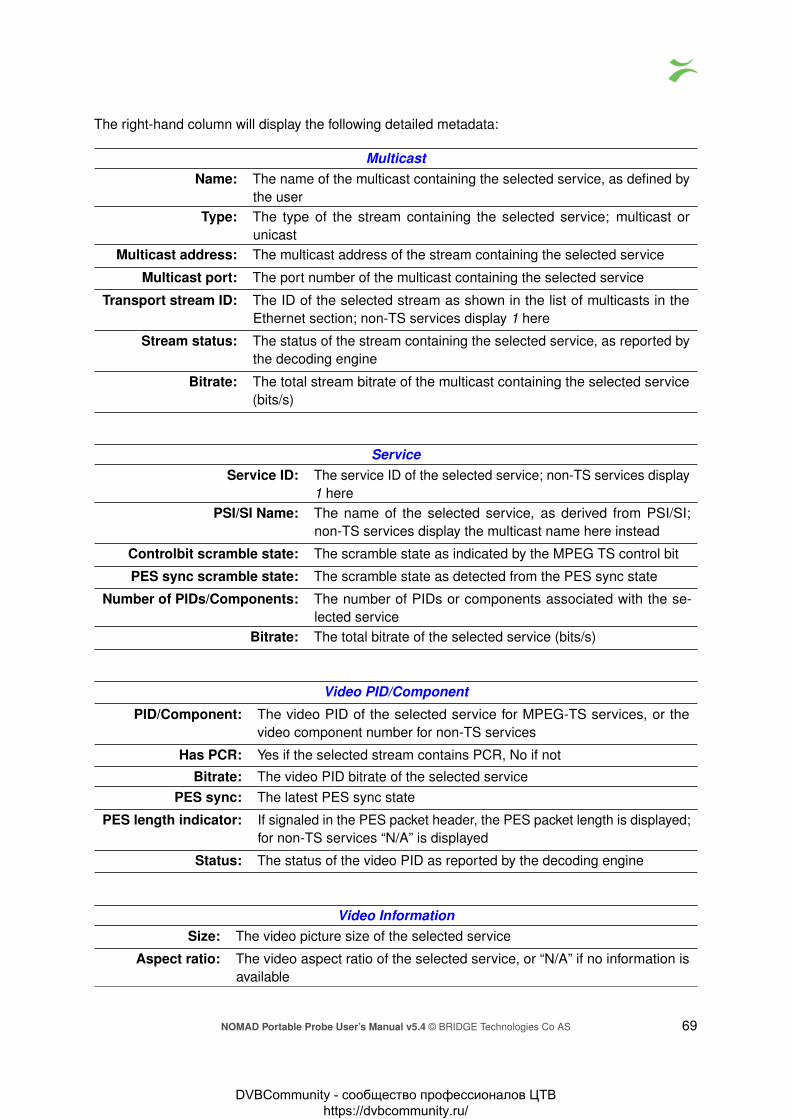
The right-hand column will display the following detailed metadata:
MulticastName: The name of the multicast containing the selected service, as defined by
the userType: The type of the stream containing the selected service; multicast or
unicastMulticast address: The multicast address of the stream containing the selected service
Multicast port: The port number of the multicast containing the selected service
Transport stream ID: The ID of the selected stream as shown in the list of multicasts in theEthernet section; non-TS services display 1 here
Stream status: The status of the stream containing the selected service, as reported bythe decoding engine
Bitrate: The total stream bitrate of the multicast containing the selected service(bits/s)
ServiceService ID: The service ID of the selected service; non-TS services display
1 herePSI/SI Name: The name of the selected service, as derived from PSI/SI;
non-TS services display the multicast name here instead
Controlbit scramble state: The scramble state as indicated by the MPEG TS control bit
PES sync scramble state: The scramble state as detected from the PES sync state
Number of PIDs/Components: The number of PIDs or components associated with the se-lected service
Bitrate: The total bitrate of the selected service (bits/s)
Video PID/Component
PID/Component: The video PID of the selected service for MPEG-TS services, or thevideo component number for non-TS services
Has PCR: Yes if the selected stream contains PCR, No if not
Bitrate: The video PID bitrate of the selected servicePES sync: The latest PES sync state
PES length indicator: If signaled in the PES packet header, the PES packet length is displayed;for non-TS services “N/A” is displayed
Status: The status of the video PID as reported by the decoding engine
Video InformationSize: The video picture size of the selected service
Aspect ratio: The video aspect ratio of the selected service, or “N/A” if no information isavailable
NOMAD Portable Probe User’s Manual v5.4 © BRIDGE Technologies Co AS 69
DVBCommunity - cообщество профессионалов ЦТВ https://dvbcommunity.ru/

Pixel aspect ratio: The video pixel aspect ratio of the selected service, or “N/A” if no informationis available
Codec: The video encoding format of the selected service
Quality: The video sampling format of the selected service
Frame rate: The video frame rate of the selected service (Hz)
Audio PID/Component
PID/Component: The audio PID of the selected service for MPEG-TS services, or the audiocomponent number for non-TS servicesNote that there may be several audio PIDs or components associated with aservice
Type: The audio encoding standard
Has PCR: Yes if the selected Audio PID contains PCRLanguage: The language of the audio, as defined in the MPEG-TS Program Map Table
(PMT)
Bitrate: The audio bitrate for this PID or component (bit/s)
Is scrambled: ‘Yes’ if the audio PID is scrambled.Peak level: The peak audio level in dB, detected during a period of approximately 0.4
secondsAverage level: The average audio level in dB, measured over a period of approximately 0.4
seconds
Audio Information PID/Component
Codec: The audio encoding format
Samplerate: The audio sample rate (Hz)
Channels: The number of audio channels represented by the audio PID or component
Layout: The audio channel layout
Format: The binary format of the audio stream
Bitrate: The effective audio bitrate (bit/s)
70 NOMAD Portable Probe User’s Manual v5.4 © BRIDGE Technologies Co AS
DVBCommunity - cообщество профессионалов ЦТВ https://dvbcommunity.ru/

6.4.2 Multicasts — Parameters — Fields
The Multicasts — Parameters — Fields view enables selection of the parameters to be displayedin the Multicasts — Parameters view. Note that thumbnails must also be enabled in the Setup —Params view for thumbnail availability.
6.4.3 Multicasts — Summary
The intention of this page, together with the alarm list, is to provide enough information for theoperator to immediately see if there is anything seriously wrong with one or more Ethernet inputstreams. The overall status for the Full Service Monitoring (FSM) is also shown.
NOMAD Portable Probe User’s Manual v5.4 © BRIDGE Technologies Co AS 71
DVBCommunity - cообщество профессионалов ЦТВ https://dvbcommunity.ru/

Throughout this view the bulb colors indicate the most severe active alarm. They may be green (noalarm), yellow (warning), orange (error) or red (major). The bulb color is based on user defined alarmseverity settings for each alarm. A grey bulb indicates that monitoring is disabled.
The following Ethernet parameters are shown:
Eth streams withactive alarms: Shows the number of streams that are presently in an alarmstate (0–50). Note that the number of alarms counted refersto default settings, and alarms disabled by the user will still becounted.
Interface bitrate: This is the total bitrate sensed on eth0. It should be greaterthan or equal to the Monitoring bitrate.
Monitoring: This is the total number of Ethernet streams monitored (0–50)and the total bitrate for these streams.
Full Service Monitoring status: The number of enabled FSM services / number of OK FSMservices
The probe is capable of monitoring up to 50 streams simultaneously. The probe splits streams intopages for easy handling. Each of the 20 predefined pages can be given a name and have a userdefined number of streams associated.
Part of the page-status is error-second statistics for the fundamental parameters MLR, RTP, overfland nosig summed across all streams belonging to that page.
The error-second statistics interval is selected by clicking the buttons. For example, clicking theES–8h button will present error-seconds for the last 8 hours. If 10 streams for a page have beenwithout signal for the last 8 hours, the nosig will show as 80hours.
The following parameters are presented (note that the error second values are accumulated fromprobe boot time, and they will only be cleared by reboot or by clicking the Clear all counters button inthe Main view):
‘Bulb’: The bulb indicates the most severe active alarm for any of the streams on the page.Active alarms are located on top of the alarm list. The alarm severity is reflected bythe color of the associated icon.Next to the bulb is a link that will lead to the Monitoring page if pressed. TheMonitoring page will present error-second statistics for each stream individually.
OK: Shows how many of the streams monitored on this page are without active alarms
ES(MLR): Number of seconds in selected period with continuity counter errors in the MPEG2transport stream (which corresponds to the number of seconds with non-zero MediaLoss Rate).
ES(RTP): Number of seconds in selected period with RTP packet-drop
ES(overfl): Number of seconds in selected period with bitrate overflow
ES(nosig): Number of seconds in selected period where no signal (i.e. no data) was received
72 NOMAD Portable Probe User’s Manual v5.4 © BRIDGE Technologies Co AS
DVBCommunity - cообщество профессионалов ЦТВ https://dvbcommunity.ru/
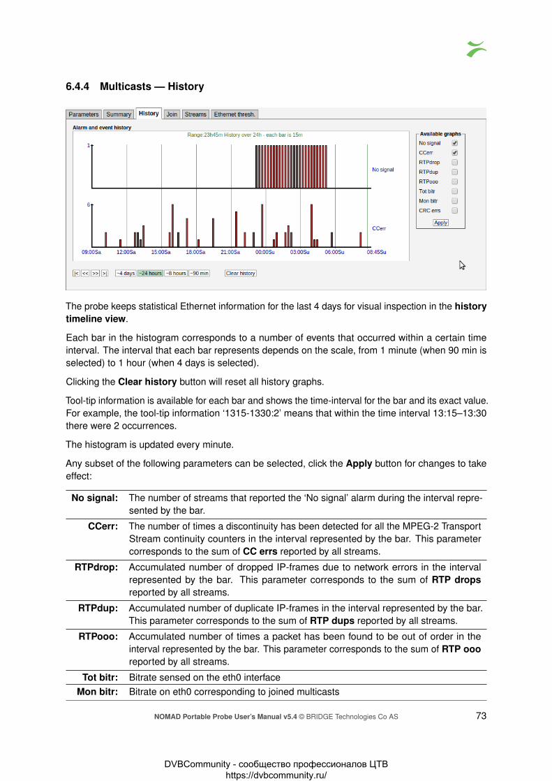
6.4.4 Multicasts — History
The probe keeps statistical Ethernet information for the last 4 days for visual inspection in the historytimeline view.
Each bar in the histogram corresponds to a number of events that occurred within a certain timeinterval. The interval that each bar represents depends on the scale, from 1 minute (when 90 min isselected) to 1 hour (when 4 days is selected).
Clicking the Clear history button will reset all history graphs.
Tool-tip information is available for each bar and shows the time-interval for the bar and its exact value.For example, the tool-tip information ‘1315-1330:2’ means that within the time interval 13:15–13:30there were 2 occurrences.
The histogram is updated every minute.
Any subset of the following parameters can be selected, click the Apply button for changes to takeeffect:
No signal: The number of streams that reported the ‘No signal’ alarm during the interval repre-sented by the bar.
CCerr: The number of times a discontinuity has been detected for all the MPEG-2 TransportStream continuity counters in the interval represented by the bar. This parametercorresponds to the sum of CC errs reported by all streams.
RTPdrop: Accumulated number of dropped IP-frames due to network errors in the intervalrepresented by the bar. This parameter corresponds to the sum of RTP dropsreported by all streams.
RTPdup: Accumulated number of duplicate IP-frames in the interval represented by the bar.This parameter corresponds to the sum of RTP dups reported by all streams.
RTPooo: Accumulated number of times a packet has been found to be out of order in theinterval represented by the bar. This parameter corresponds to the sum of RTP oooreported by all streams.
Tot bitr: Bitrate sensed on the eth0 interfaceMon bitr: Bitrate on eth0 corresponding to joined multicasts
NOMAD Portable Probe User’s Manual v5.4 © BRIDGE Technologies Co AS 73
DVBCommunity - cообщество профессионалов ЦТВ https://dvbcommunity.ru/

CRC errs: Detected CRC errors. Ethernet CRC errors are most likely caused by a bad cable ora misconfigured router. A CRC error may impact packet loss measurements such asCC errors and RTP errors.
Note that the history graphs show the sum for all streams being analyzed across all pages. So forexample, if two streams experience No signal at the same time the No signal graph will increase by2.
6.4.5 Multicasts — Join
In order for the defined Ethernet multicasts to be monitored by the probe, they must be joined.The Multicasts — Join view and the Multicasts — Streams view allow the user to select whichmulticasts that are joined by the probe.
Streams defined in the Multicasts — Streams view will appear as available streams on the left handside of the arrows in this view. Select streams to be monitored by clicking them and moving them tothe right hand side of this view using the arrow. Changes should be confirmed by clicking the Applychanges button.
The probe can join a maximum of 50 uni/multicasts, these may be freely associated with the 20 probepages. The streams will be presented in the Joined multicasts list in the Multicasts — Parametersview.
It is possible to flush or fill the multicasts/unicasts to monitor list by clicking the corresponding button.Note that these operations will take effect immediately; it is not necessary to click Apply changes formulticasts to be joined or unjoined.
74 NOMAD Portable Probe User’s Manual v5.4 © BRIDGE Technologies Co AS
DVBCommunity - cообщество профессионалов ЦТВ https://dvbcommunity.ru/

6.4.6 Multicasts — Streams
In this view the operator can define multicasts available to the probe and associate a name with eachmulticast address. This name will be used by the probe when referring to the multicast. If no namehas been defined the probe will use the multicast address:port notation.
It is possible to add, delete or edit several entries simultaneously. Several entries are selected byusing the regular Ctrl + click or Shift + click functionality. When adding new entries the currentdialogue values will be used as the template with the values for Name and Address incremented foreach.
Note that both multicast and unicast addresses can be entered here.
Distribute ETR engines button will distribute unused ETR engines among selected streams if noETR engine already assigned. An ETR engine is considered used if one or more ETR with thatengine is enabled.
The search field in the upper right corner of the view allows the user to type a text string, and themulticast list is updated to display only streams matching the specified text.
Clicking Add new or selecting one or more multicasts and clicking Edit selected will open theMulticast — Streams — Edit pop-up menu. When multicasts have been defined, clicking Joinselected will join the selected multicasts and enable monitoring. The probe will only analyze joinedmulticasts. Clicking Join all will join all multicasts in the list (up to the licensed maximum numberof channels). Unjoining one or more multicasts is done by selecting multicasts and clicking Unjoinselected or by clicking Unjoin all.
When the Edit button is clicked it is possible to define the following multicast parameters (note thatsome parameters are only relevant and selectable when the probe is equipped with the ETR 290option and T2MI option respectively):
NOMAD Portable Probe User’s Manual v5.4 © BRIDGE Technologies Co AS 75
DVBCommunity - cообщество профессионалов ЦТВ https://dvbcommunity.ru/

GeneralName: A name should be assigned to each unicast/multicast. The name will be
used throughout the NOMAD user interface when referring to this stream.It may also be used by an external management system like the VBCController.
Address: The IP address of the unicast or multicast. For a T2MI inner stream entera dummy address.
Port: The port number of the unicast or multicast. For a T2MI inner streamenter a dummy port number.
Ethernet thresholds: The Ethernet thresholds specify various error limits. Selectable Ethernetthresholds templates are defined in the Multicasts — Ethernet thresh.view. For a T2MI stream select a dummy threshold template.
VBC thresholds: The VBC thresholds specify various error limits to be used by VBCController to generate alarms. These thresholds are only relevant if theVBC Controller is used. VBC threshold templates are defined in theSetup — VBC thresh. view.
Join stream: Check the ‘Join stream’ check box to join a multicast or unicast. Onlyjoined streams are analyzed. A stream may also be joined from theMulticasts — Join or Multicasts — Streams views, and the status ofthis check box will be updated accordingly.
Join interface: Select which interface to join the selected multicast. The data interface(s)are listed, as well as any enabled VLAN interface (defined in Setup —VLANs).
Page: For easy navigation, each stream can be assigned a specific page. Thenames of the pages are defined in Setup — Pages.
76 NOMAD Portable Probe User’s Manual v5.4 © BRIDGE Technologies Co AS
DVBCommunity - cообщество профессионалов ЦТВ https://dvbcommunity.ru/

SSMSSM source 1: If source specific multicasts (SSM) is enabled in the NOMAD and a zero source
address is specified for a multicast it will be joined using IGMP version 2 (i.e.without a source). This allows both source specific multicasts and non-sourcespecific multicasts to co-exist in the same network and be joined by the NOMAD.
SSM source 2: Additional SSM source addresses may be specified to enable back-up solutions.Note that it is the operator’s responsibility to ensure that a multicast is onlytransmitted by one SSM source at any time.
SSM source 3: Additional SSM source addressSSM source 4: Additional SSM source addressSSM source 5: Additional SSM source address
ETR (ETR290 Option)
Enable ETR: ETR monitoring of a stream will not take place unless it is enabled by thissetting. This parameter is only relevant if the probe is ETR enabled.
Select ETR engine: If the probe is licensed for several Ethernet ETR engines the user mayselect which engine should be used to analyze the stream. The defaultETR engine selection is Ethernet1. It is also possible to use the DistributeETR engines button described above to assign streams to engines.
NOMAD Portable Probe User’s Manual v5.4 © BRIDGE Technologies Co AS 77
DVBCommunity - cообщество профессионалов ЦТВ https://dvbcommunity.ru/

ETR thresholds: The ETR thresholds specify various error limits and alarm conditions.Selectable ETR thresholds templates are defined in the ETR 290 — ETRthresh. view. The round-robin cycling time is also defined by this thresholdtemplate. This parameter is only relevant if the probe is ETR enabled.
PID thresholds: The PID thresholds specify various error limits and alarm conditions.Selectable PID thresholds templates are defined in the ETR 290 — PIDthresh. view. This parameter is only relevant if the probe is ETR enabled.
Service thresholds: The Service thresholds selection defines various error limits and alarmconditions. Selectable service thresholds templates are defined in theETR 290 — Service thresh. view. This parameter is only relevant if theprobe is ETR enabled.
Reference table set: The Reference table set selection is used to compare the tables in thetransport stream with a set of stored tables. These tables are defined inthe ETR 290 — Gold TS thresholds view.
T2MI (T2MI Option)
Container stream: For an T2MI inner stream the container stream (outer stream) must bespecified. Select the container stream from the drop-down menu. Forstreams other than T2MI inner streams (none) should be selected.
Data PID: The container stream PID carrying the inner stream
PLP ID: The PLP ID for the inner stream. Select a fixed PLP ID value from thedrop-down menu or specify that the first detected PLP ID should be used.
78 NOMAD Portable Probe User’s Manual v5.4 © BRIDGE Technologies Co AS
DVBCommunity - cообщество профессионалов ЦТВ https://dvbcommunity.ru/

Redundancy
Has FEC: The stream carries COP3 (SMPTE 2022-5) Forward Error Correction. Ifenabled, statistics about FEC drops and correctible errors will be reported forthe stream.
First stream: For a Seamless Protection Switching (SMPTE 2022-7) protected stream, selectthe first of the two redundant RTP streams here. For other streams, (none)should be selected.
Second stream: Select the second of the two redundant RTP streams here.
Seamless Protection Switching (SMPTE 2022-7) monitors the same stream transmitted twice. Theprobe verifies that the two streams combined do not have packet loss and the jitter between the twostreams. When two multicast/unicast streams are selected, the probe will report errors report errors ifthe same RTP packets are missing from both streams. Errors are also reported if the timing betweenthe two stream exceeds the threshold settings.
Seamless Protection Switching has been optimized for monitoring SDI over IP (SMPTE 2022-6)streams.
6.4.7 Multicasts — Ethernet thresh.
NOMAD Portable Probe User’s Manual v5.4 © BRIDGE Technologies Co AS 79
DVBCommunity - cообщество профессионалов ЦТВ https://dvbcommunity.ru/
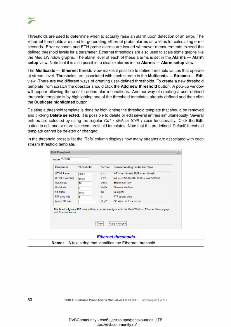
Thresholds are used to determine when to actually raise an alarm upon detection of an error. TheEthernet thresholds are used for generating Ethernet probe alarms as well as for calculating error-seconds. Error seconds and ETH probe alarms are issued whenever measurements exceed thedefined threshold levels for a parameter. Ethernet thresholds are also used to scale some graphs likethe MediaWindow graphs. The alarm level of each of these alarms is set in the Alarms — Alarmsetup view. Note that it is also possible to disable alarms in the Alarms — Alarm setup view.
The Multicasts — Ethernet thresh. view makes it possible to define threshold values that operateat stream level. Thresholds are associated with each stream in the Multicasts — Streams — Editview. There are two different ways of creating user-defined thresholds. To create a new thresholdtemplate from scratch the operator should click the Add new threshold button. A pop-up windowwill appear allowing the user to define alarm conditions. Another way of creating a user-definedthreshold template is by highlighting one of the threshold templates already defined and then clickthe Duplicate highlighted button.
Deleting a threshold template is done by highlighting the threshold template that should be removedand clicking Delete selected. It is possible to delete or edit several entries simultaneously. Severalentries are selected by using the regular Ctrl + click or Shift + click functionality. Click the Editbutton to edit one or more selected threshold templates. Note that the predefined ‘Default’ thresholdtemplate cannot be deleted or changed.
In the threshold presets list the ‘Refs’ column displays how many streams are associated with eachstream threshold template.
Ethernet thresholdsName: A text string that identifies the Ethernet threshold
80 NOMAD Portable Probe User’s Manual v5.4 © BRIDGE Technologies Co AS
DVBCommunity - cообщество профессионалов ЦТВ https://dvbcommunity.ru/

IAT:MLR error: This threshold contains error limits for IAT (Inter-packet Arrival Time) andMLR (Media Loss Rate).The IAT limit is the first parameter (before the colon), the MLR limit is thelast parameter. If the IAT limit is exceeded the alarm ‘IAT >= err-thresh’ willbe raised. If the MLR limit is exceeded the alarm ‘MLR >= err-thresh’ will beraised. The severity (and hence the color used in the MediaWindow view)for IAT:MLR errors depend on the severity assigned to these alarms in theAlarms — Alarm setup view.Note that error seconds based on MLR are counted regardless of thisthreshold if one or more packets are missing.
IAT:MLR warning: This threshold contains warning limits for IAT (Inter-packet Arrival Time) andMLR (Media Loss Rate).The IAT limit is the first parameter (before the colon), the MLR limit is the lastparameter. If the IAT limit is exceeded the alarm ‘IAT >= warn-thresh’ will beraised. If the MLR limit is exceeded the alarm ‘MLR >= warn-thresh’ will beraised. The severity (and hence the color used in the MediaWindow view)for IAT:MLR errors depend on the severity assigned to these alarms in theAlarms — Alarm setup view.
Max bitrate: The maximum bitrate in Mbit/s. An alarm will be raised if the stream bitrateexceeds the maximum bitrate.
Min bitrate: The minimum bitrate in Mbit/s. A value of 0 will never generate an alarm. Avalue of 0.1 Mbit/s will generate an alarm if the minimum bitrate threshold isless than 0.1 Mbit/s.
No signal: Number of milliseconds without receiving any signal before the ‘No signal’alarm is raised
RTP drop limit: If the number of lost RTP packets exceeds the RTP drop limit an alarmwill be raised. Note that error seconds based on packet drops are countedregardless of this threshold.
Ignore PID loss: A comma separated list of PIDs for which the probe should ignore packetloss. Packet loss that affects these PIDs will not result in an error-secondcount, and the ETR monitoring engine will not count these errors.
NOMAD Portable Probe User’s Manual v5.4 © BRIDGE Technologies Co AS 81
DVBCommunity - cообщество профессионалов ЦТВ https://dvbcommunity.ru/

6.5 MW (Media Window)
The MW Media Window view provides an at-a-glance status for each of the multicasts/unicasts beingmonitored. From the graphs it is easy to see the jitter characteristics of the signal and if there ispacket loss or CC errors present in the signal. Periods of no signal are also displayed.
The measurements are always aggregated over a time interval – typically one second. The IAT(max)is the maximum time measured between two neighboring IP frames within the measurement timeinterval (the peak packet Inter-arrival time). IAT is expressed in milliseconds.
The MLR is the peak estimated number of lost MPEG-2 Transport Stream packets inside any secondwithin the actual time period. The number of lost TS packets is derived from the continuity countersinside the TS packet headers.
A common scenario is to have 7 TS packets per UDP frame. Losing an IP packet will therefore usually(but not always) result in an MLR of 7 (not always the case because some TS packets such as nullpackets or PCR packets do not carry a valid CC field).
Bridge Technologies’ patented Media Window presents both jitter and packet loss measurements inone graph, with jitter (IAT) values growing upwards (+ve Y) and packet loss (MLR) growing downwards(-ve Y). Each sample along the x-axis corresponds to a measurement time-interval that depends onthe range of the graph selected. Periods of no sync are also displayed in the graph.
Error-second statistics for the graph-interval is displayed to the right. As the graphs are zoomed orscrolled the error-second statistics is updated as well as the graphs.
Tool-tip provides the exact jitter (IAT) and packet loss (MLR) values for a selected bar in a selectedgraph, the denotation is IAT::MLR. The current graph value displayed under ‘Running’ provides themaximum MLR and IAT values measured during the last 3 seconds.
Red color is used to indicate that within the period represented by the bar there has been one ormore occurrences of no-signal. Orange is used to indicate error while yellow indicates warning. Theerror and warning thresholds are allocated to each multicast in the Multicasts — Streams view.
The user determines whether only multicasts associated with the currently selected page should bedisplayed (by clicking the Cur page button), or if all joined multicasts should be presented in one
82 NOMAD Portable Probe User’s Manual v5.4 © BRIDGE Technologies Co AS
DVBCommunity - cообщество профессионалов ЦТВ https://dvbcommunity.ru/

list (by clicking the All button). The time window buttons allow selection of x-axis resolution in thegraphs, and by using the arrow buttons it is possible to move the timeline to view an error incidentmore accurately. Clicking Clear will clear all graphs. Note that clearing graphs cannot be undone.Clicking the +1 button will display the next page. Clicking the –1 button will display the previous page.
By zooming and panning the user can pinpoint more accurately when errors occurred. In the abovediagram tooltip reveals that ‘No signal’ occurred between 9:15 and 9:20.
6.5.1 Media Window — Selected channel
NOMAD Portable Probe User’s Manual v5.4 © BRIDGE Technologies Co AS 83
DVBCommunity - cообщество профессионалов ЦТВ https://dvbcommunity.ru/

The Media Window — selected channel view is activated by clicking a multicast label in the MWpage. By clicking the pop-up button a pop-up window will appear, the user can have this separatewindow showing selected channel even when navigating away from the probe. This provides theability to monitor media windows for several streams without starting several browser sessions. Whenin the pop-up Media Window by pressing some where in the graph, the field will get zoomed in.
This hi-resolution version of the Media Window reveals more details than the compressed version.There are 3 times more samples along the X-axis, and the graph indicates visually the error andwarning thresholds. Note that the time windows of the regular Media Window and Media Window— selected channel are not exactly the same, even if the same time window has been selected forboth views.
6.5.2 Media Window — Bandwidth graph
By clicking the BW:MLR button the graph displays the peak bandwidth as a function of time. Thenegative part of the composite graphs is still the packet loss (i.e. the MLR).
If the stream contains a transport stream (mapping TS/x) the bitrate corresponds to the Multicastsparameter Net bitrate (i.e. bitrate excluding null packets). Otherwise the bitrate is the UDP payloadbitrate corresponding to the Multicasts parameter Curr bitrate.
The bandwidth error threshold is configured in the Multicasts — Ethernet thresh. view.
84 NOMAD Portable Probe User’s Manual v5.4 © BRIDGE Technologies Co AS
DVBCommunity - cообщество профессионалов ЦТВ https://dvbcommunity.ru/
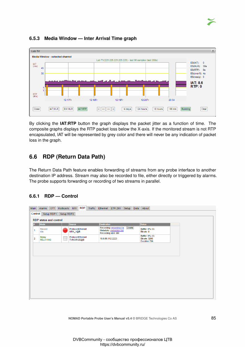
6.5.3 Media Window — Inter Arrival Time graph
By clicking the IAT:RTP button the graph displays the packet jitter as a function of time. Thecomposite graphs displays the RTP packet loss below the X-axis. If the monitored stream is not RTPencapsulated, IAT will be represented by grey color and there will never be any indication of packetloss in the graph.
6.6 RDP (Return Data Path)
The Return Data Path feature enables forwarding of streams from any probe interface to anotherdestination IP address. Stream may also be recorded to file, either directly or triggered by alarms.The probe supports forwarding or recording of two streams in parallel.
6.6.1 RDP — Control
NOMAD Portable Probe User’s Manual v5.4 © BRIDGE Technologies Co AS 85
DVBCommunity - cообщество профессионалов ЦТВ https://dvbcommunity.ru/

Click the icons in the Control tab to activate or de-activate an RDP engine. There are different iconsfor controlling RDP engines depending on whether they are configured to relay or record. The stateof each RDP engine is restored after a reboot.
For recordings and triggered recordings the last recording is made available in the Destination columnalong with the metadata file. The metadata file contains basic information about the recording suchas the recording size, list of PIDs and CC-errors for each PID. In the case of triggered recording, thealarm causing the recording is also included. Pressing the Delete button deletes the recording. Fortriggered recordings the number of recordings is stated in the Status column. Pressing the Deletebutton resets this counter. The buffer utilization is stated as a percentage and should never approach100% for correct relaying or recordings.
6.6.2 RDP — Setup
Each of the RDP engines is configured separately. First the Mode is selected. Depending on themode either the Relay or Record settings needs to be configured. The Input selects the stream orinterface to relay or record.
These are the settings:
Mode and Input
Mode: Select whether this RDP engine should relay, record or trigger-record.
Source interface: The source interface drop-down menu allows selection of available inputsignals. Note that ETR290 analysis of a demodulated signal should belocked (round-robin looping disabled) to obtain a continuous stream for ASIand RF signals.
Source Stream: When Ethernet input is selected the user selects the stream to forward orrecord. Ethernet streams being joined/monitored by the probe are availablefor selection.
86 NOMAD Portable Probe User’s Manual v5.4 © BRIDGE Technologies Co AS
DVBCommunity - cообщество профессионалов ЦТВ https://dvbcommunity.ru/

Content: The user selects the service to be relayed or recorded, or alternatively selectsthat the complete stream should be used. The PIDs associated with theservice are automatically displayed in the ‘Selected PIDs’ field, and thesemay be edited if required.
Selected PIDs: The user can specify the PIDs to be selected, default is all PIDs. TypicallyPAT and PMT PIDs should be forwarded in addition to video and audio PIDs,however this depends on the equipment receiving the forwarded stream.
When mode Relay over IP has been selected, the RDP parameters are:
RDP EthernetIPv4-address: The unicast address or multicast address to forward to. Multicast addresses
are in the range 224.0.0.0 – 239.255.255.255.
Port: The port to forward to. The combination of IP address and port fullydescribes the destination address.
TTL: The Time-To-Live flagging of the relayed signal. The default value is 64.
Timeout: The relaying period in minutes. If the value 0 is selected, no timeout applies,and relaying will continue until it is stopped manually.
Encapsulation: The encapsulation format of the relayed stream. UDP or RTP may beselected.
Relay via interface: The available interfaces for forwarding the stream are listed.
When mode Record or Trigger recording has been selected the options are:
Record and trigger options
Rec timeout: The maximum recording time in seconds. This setting enables the user tolimit recordings of low-bitrate streams.
Rec size: The total file size of the recording. When in alarm trigger mode the resultingrecording will consist of a fixed sized portion of data before the alarm israised and the remaining recording from data after the trigger occurred.
Protect: When in alarm trigger mode the user may select to protect a recording frombeing overwritten due to a new alarm occurrence. The user may selectbetween ‘Never overwrite’, ‘Do not protect’, ‘30 seconds’, ‘60 seconds’ and‘5 minutes’.
Alarm trigger 1–3: Select a maximum of three different alarms that should trigger recording.Note that a recording will start upon a transition from status OK to statusalarm. Alarms that have been disabled in the Alarm — Alarm setup viewwill be shown in brackets – these will never trigger a recording.
The maximum recording size depends on the amount of free disk on the probe, up to a maximum of500 Mbyte.
NOMAD Portable Probe User’s Manual v5.4 © BRIDGE Technologies Co AS 87
DVBCommunity - cообщество профессионалов ЦТВ https://dvbcommunity.ru/

6.7 Traffic
6.7.1 Traffic — Protocols
The Protocols view allows monitoring of IP traffic on the selected port in terms of the protocols used.
The interface can be selected using the drop-down at the bottom of the page. Clicking the Clearstatistics button will reset displayed values.
The following measurements are presented, depending on which statistic is selected:
StatisticsStatistic: The protocol for which the following measurements apply
Cur bitrate: The current total bitrate for this protocol (measured over the last 1s period)
Max bitrate: The maximum bitrate during any 1s period
Min bitrate: The minimum non-zero bitrate during any 1s period
Frames/sec: Traffic speed in number of IP packets per second
Frames: Number of Ethernet framesFrames %: Percentage of total number of frames
Min flen: Minimum Ethernet frame length
Max flen: Maximum Ethernet frame length
BitratesStatistic: As above
Cur bitrate: As aboveBitrates: A graph displaying the bitrate over time, displaying the last five minutes
Bitrate graph: Click the bitrate graph button to display a detailed bitrate graph for the specifiedprotocol
Frames
88 NOMAD Portable Probe User’s Manual v5.4 © BRIDGE Technologies Co AS
DVBCommunity - cообщество профессионалов ЦТВ https://dvbcommunity.ru/

Statistic: As aboveFrames/sec: Traffic speed for this protocol expressed in number of IP packets per second
Frames: A graph displaying frames per second over time, displaying the last five minutes
Frames graph: Click the frames graph button to display a detailed frames per second graph forthe specified protocol
Interface statisticsLink status: Displays whether the interface is up or down
Link speed: Displays the interface speeds, as bits per second
Link duplex: Indicates whether the interface is operating at full or half duplex
UDP unicasts: The number of detected UDP unicastsUDP multicasts: The number of detected UDP multicasts
COP3 Correctable: Total count of dropped payload IP packets that are correctable by theFEC
COP3 Uncorrectable: Total count of dropped payload IP packets that cannot be corrected bythe FEC
COP3 Late: Payload or FEC packets are received slightly too late according to thebuffer model and may result in errors in another implementation of thespecifications. The number of packets with this error.
COP3 Errors: Either the L/D parameters are not consistent across the streams orpayload/FEC packets are received too late or too early according to thebuffer model. The number of packets with these errors.
6.7.2 Traffic — Detect
The Traffic Detect view displays all UDP traffic sensed by the probe. Note that promiscuous networkmode should be enabled in the Setup — Params view for the probe to detect all traffic, and not onlymulticasts already joined by the probe. Note that generally the upstream switch or router will not
NOMAD Portable Probe User’s Manual v5.4 © BRIDGE Technologies Co AS 89
DVBCommunity - cообщество профессионалов ЦТВ https://dvbcommunity.ru/

output streams that are not joined by downstream equipment, i.e. usually only joined streams will beavailable for monitoring.
If the unicast/multicast destination address is known to the probe (i.e. listed in the Multicasts —Streams view) the stream’s Name is looked up, otherwise a generic name is used.
When the Traffic — Detect view is entered after probe booting, the probe will continuously try todetect streams. Click the View list offline button to view the stream list in offline mode. Click theRefresh button to update the stream list in offline mode.
The source address makes it possible for the probe to distinguish between multicasts with the samedestination IP address and port, provided that Source specific multicasts has been enabled in theSetup — Params view.
If the stream is currently joined by the probe (i.e. the probe is currently monitoring the stream), theJoined field is set to yes.
VLAN ID is only available if the probe has enabled VLAN tagging for eth0 (Multicasts — Parame-ters).
Detected streams can be added to the probe’s stream list by selecting streams and clicking theAdd selected to stream list. To add all detected streams the Add all to stream list button can bepressed. Only streams not already in the probe’s stream list are considered. Clicking the Exportbutton will generate an XML-file that opens in a new window.
A drop down menu allows filtering of detected streams, making is possible to view streams of aspecific type only. Stream types are defined in the Traffic — Filter setup view. If the AEO option isenabled for the probe the Detect list will contain the following additional columns: Mapping, signal,RTP drops, CC errors and Bitrate. These parameters are the same as on the Multicasts page.
i©: Click the blue information icon to pop up the detailed stream info.
Dst address: The multi- or unicast addressSrc address: The streams source address
Name: The stream name, as defined in the Multicasts — Streams view. A generic namewill be used for multi- or unicasts not defined by the user.
VLAN ID: The VLAN ID of the streamJoined: If the stream is joined by the probe this field will read ‘Yes’.
CPU: The probe CPU used to analyze the stream (1-7)
Mapping: The transport stream to IP mapping. Typically seven transport stream packets aremapped into one IP packet.
Signal: The duration of stream availability
RTP drops: The number of detected RTP drops for the stream. This is only valid if the streamis RTP encapsulated.
CC errors: The number of detected continuity counter errors for the stream.
Bitrate: The stream bitrate
90 NOMAD Portable Probe User’s Manual v5.4 © BRIDGE Technologies Co AS
DVBCommunity - cообщество профессионалов ЦТВ https://dvbcommunity.ru/

6.7.3 Traffic — Filter statistics
The Traffic — Filter statistics view makes it possible to view statistics for different stream types.Stream types are defined by the user in the Traffic — Filter setup view.
Statistics is displayed for a time period selected by clicking one of the time duration buttons.
Filter statistics:Filter: The filter name, as defined by the user in the Traffic — Filter setup view.
Streams: The number of streams matching the associated filter.
Bitrate: The total summed bitrate for streams matching the associated filter.
RTP loss %: Percentage of time an average stream that matches the filter experiencesRTP packet loss inside selected time period.Example: If the Last 1m period is selected and there are totally three streamscaught by filter:
• stream A: present for 60 seconds, 4 RTP error seconds
• stream B: present for 30 seconds, 0 RTP error seconds
• stream C: present for 30 seconds, 5 RTP error seconds
RTP loss % = 9ES / 120sRTP loss % = 9ES / 3streams / 120s *100% = 7.5%
MLR %: Percentage of time an average stream that matches the filter experiencesMLR inside selected time period.The calculation is similar to that for RTP loss %.
Avg str bitr: The average bitrate for streams matching the associated filter.
NOMAD Portable Probe User’s Manual v5.4 © BRIDGE Technologies Co AS 91
DVBCommunity - cообщество профессионалов ЦТВ https://dvbcommunity.ru/

Avg str duration: The stream duration is calculated for each stream by identifying the stream’saverage stream alive counter inside the selected time period, then multiply by2.The stream alive counter is the number of seconds the stream has existed.This gives accurate results for streams that begin within the selected timeperiod, but may give up to twice the real bitrate for streams that begin (long)before the selected period.Examples: a stream exists for 100 seconds, and begins within the selectedperiod. The calculation becomes:Stream duration = (1+2+. . . +100)/100*2 = 101If the same stream started 50 seconds before the selected period, the calcu-lation becomes:Stream duration = (51+52+. . . +100)/50*2 = 151
Clicking the icon next to each value brings up the detailed graph window.
The detailed graph window displays up to 4 days of history.
Trending
Clicking the Trending last 60m button will present at-a glance trending graphs for each parameterfor the last 60 minutes.
92 NOMAD Portable Probe User’s Manual v5.4 © BRIDGE Technologies Co AS
DVBCommunity - cообщество профессионалов ЦТВ https://dvbcommunity.ru/

Clicking a graph icon displays the corresponding detailed graph for the selected filter. Clicking thetrend graphs itself will bring up the same detailed graph but will plot all the filters so that they caneasily be compared.
The detailed trending graph above displays MLR errors for all filters.
6.7.4 Traffic — Filter setup
The Traffic — Filter setup view makes it possible to define stream filter requirements affecting theTraffic — Detect and Traffic — Filter statistics views. Ten filters can be defined and enabled bythe user.
Statfilter settings:
Name: A text string defining the filter
Enabled: Only enabled filters are in use
Streams: The number of streams matching filter requirements
Cast: The type of stream: No filtering, Only unicasts or Only multicasts
RTP: The RTP mode: No filtering, Only with RTP header or Only without RTP header
VLAN: VLAN selection mode: No filtering, Only tagged traffic, Only untagged traffic orRequire matching specified value (a specific VLAN ID).
NOMAD Portable Probe User’s Manual v5.4 © BRIDGE Technologies Co AS 93
DVBCommunity - cообщество профессионалов ЦТВ https://dvbcommunity.ru/
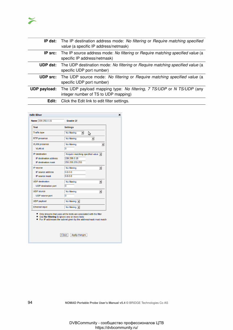
IP dst: The IP destination address mode: No filtering or Require matching specifiedvalue (a specific IP address/netmask)
IP src: The IP source address mode: No filtering or Require matching specified value (aspecific IP address/netmask)
UDP dst: The UDP destination mode: No filtering or Require matching specified value (aspecific UDP port number)
UDP src: The UDP source mode: No filtering or Require matching specified value (aspecific UDP port number)
UDP payload: The UDP payload mapping type: No filtering, 7 TS/UDP or N TS/UDP (anyinteger number of TS to UDP mapping)
Edit: Click the Edit link to edit filter settings.
94 NOMAD Portable Probe User’s Manual v5.4 © BRIDGE Technologies Co AS
DVBCommunity - cообщество профессионалов ЦТВ https://dvbcommunity.ru/

6.7.5 Traffic — Microbitrate
The Microbitrate feature allows sampling of bitrate at various sampling intervals. When enabling thisfeature, each Ethernet frame is timestamped in hardware on probe ingress. This timestamp is usedto calculate exact bitrates at various sampling intervals.
The Interval is the sampling interval of each bitrate calculation. There are 4 intervals trackedsimultaneously.
The Max interval frames is the max number of frames within one interval last second. The Maxinterval bitrate is the max sum of Ethernet frame sizes inside one interval last second converted tobits per second. This number should always be bigger or equal for shorter intervals.
Click the legends in the graph to show or hide graphs.
The above graph is a typical OTT-traffic graph where the client periodically requests limited amountsof data at maximum speed resulting in traffic that is bursting near line-speed at 1 Gbit/s for shortintervals while the average bitrate for larger intervals is only a fraction. This traffic shape is challengingfor network equipment since it demands all remaining capacity up to line speed.
NOMAD Portable Probe User’s Manual v5.4 © BRIDGE Technologies Co AS 95
DVBCommunity - cообщество профессионалов ЦТВ https://dvbcommunity.ru/

For multicast type traffic the traffic pattern will look more like the graph above. Here the bitrate ismuch more steady even for short intervals. The network never experiences near line-speed burstingsince each stream is bitrate controlled by the sender.
6.8 Ethernet
6.8.1 Ethernet — FSM
Full Service Monitoring (FSM) allows easy validation of any server reachable by the probe viaEthernet. The servers may be probed by either sending an ICMP Echo Request packet (also knownas Ping) or performing an HTTP Get request.
Up to 10 services may be defined and each service will be checked at regular intervals. Any errorswill be logged. An error is defined as no reply within 5 seconds for the Ping option or no, or incorrect,reply within 5 seconds for the HTTP option. If there are more consecutive errors than a fails thresholdvalue an alarm will be raised.
96 NOMAD Portable Probe User’s Manual v5.4 © BRIDGE Technologies Co AS
DVBCommunity - cообщество профессионалов ЦТВ https://dvbcommunity.ru/

6.8.1.1 Ethernet — FSM — Monitor
The following parameters are continuously monitored for each service:
Status: Red = active alarm, Green = no alarm
Name: User defined service nameProtocol: Type of protocol. HTTP or Ping
IP address: IP address. Must be numeric, host name is not accepted
OK: Total number of valid checksFail: Total number of invalid checksMax: Maximum response time recorded
Min: Minimum response time recorded
Current: The current (most recent) response time
Timer: Button to reset and immediately restart the service
State: Current state of the service. The states are: ‘Disabled’, ‘Waiting to send’, ‘Waitingfor reply’, ‘Got reply’ and ‘Reset’.
For convenience a manual ping field is located below the status table. By entering a valid IP addressor host name and clicking the Ping button an arbitrary server may be pinged.
The Clear all button will clear accumulated data for all enabled FSM services, but active alarms willnot be removed.
Clicking the Traceroute button will open a new window, allowing the user to trace the network routeto a specified IP address.
NOMAD Portable Probe User’s Manual v5.4 © BRIDGE Technologies Co AS 97
DVBCommunity - cообщество профессионалов ЦТВ https://dvbcommunity.ru/

6.8.1.2 Ethernet — FSM — Setup
Each of the 10 FSM services may be defined or edited by clicking on the corresponding Edit buttonin the left hand table.
The probe supports ping and generic HTTP-Get protocols for online status verification of arbitrarytargets. After completing configuration of the selected service Apply changes must be pressed tosave and apply the changes.
98 NOMAD Portable Probe User’s Manual v5.4 © BRIDGE Technologies Co AS
DVBCommunity - cообщество профессионалов ЦТВ https://dvbcommunity.ru/

These fields are common for both the ping and the HTTP-Get protocols:
Enable: Enable by checking toggle button.
Name: User-defined name of serviceProtocol: Select between ping and HTTP.
Device: Ethernet interface to use for this service.Probe cycle: Time interval in seconds to wait between each activation. A value below 30 is
not recommended.Fails threshold: The number of consecutive errors needed to raise an alarm
Hostname: The IP address for the target. Host names are supported for HTTP.
Comment: Optional comment field – maximum 100 characters
These fields are specific for the HTTP-Get protocol:
http://<IP address>: The request to send to the target, for example index.html
Expect word reply: A case sensitive word or sentence to be expected in the reply. To find asuitable string, use the Show content link. Leave this field empty to let theprobe ignore the contents of the reply.
Last reply: The last reply Show content link points to the last HTML file that wasgenerated by this service.
Port: The port used by the target server, often 80 for HTTP requests
Support cookies: If enabled, the HTTP-Get request will remember cookies returned by thetarget and provide them in subsequent requests.
NOMAD Portable Probe User’s Manual v5.4 © BRIDGE Technologies Co AS 99
DVBCommunity - cообщество профессионалов ЦТВ https://dvbcommunity.ru/

6.8.1.3 Ethernet — FSM — Syslog
The NOMAD has a built-in syslog server which captures all incoming messages (UDP, port 514).Messages are displayed in a pageable grid with the following columns: Facility, Severity, Timestamp,Hostname, Agent and Message. Currently displayed page can be exported as an XML-document.
Since the syslog server typically stores about 100 pages of messages there is a group of buttons fora fast navigation:
Newest Move to the first page
Much newer Move 10 pages backwards
Newer Move 1 page backwards
Older Move 1 page forwards
Much older Move 10 pages forwards
Oldest Move to the last page
Syslog server has a limited capacity which is usually enough to store the latest 10,000 messagesdepending on the size of the syslog messages. When a new message arrives and no storage spaceremains the oldest messages are removed.
Note that the syslog server is very sensible to time settings, so it is strongly recommended to have atime synchronization enabled.
100 NOMAD Portable Probe User’s Manual v5.4 © BRIDGE Technologies Co AS
DVBCommunity - cообщество профессионалов ЦТВ https://dvbcommunity.ru/

6.8.2 Ethernet — IGMP
The IGMP view shows all IGMP (version 2 or 3) messages detected by the probe. This includesIGMP query messages sent by routers, IGMP reply messages sent by the probe itself and IGMPreply messages sent by other probes and devices on the same subnet.
The live IGMP page can be paused by clicking the View list offline button. The IGMP messagescan be exported as XML by clicking the Export. . . button, and the list is cleared by clicking the Clearlist button.
i©: Click the blue information icon to open the IGMP record pop-up view
No: The message number since the list was cleared
Time: The probe time when the message occurred
Millisec: The milliseconds timestamp
Source: The source IP addressDestination: The destination IP address
Code: The timeout codeMessage: The interpreted IGMP message
Group: The IGMP group address
NOMAD Portable Probe User’s Manual v5.4 © BRIDGE Technologies Co AS 101
DVBCommunity - cообщество профессионалов ЦТВ https://dvbcommunity.ru/

6.8.3 Ethernet — PCAP
The NOMAD can make PCAP recordings on the data interface of up to approximately 1 Gbyte(depending on the amount of free disk) based on simple user configurable filters. The PCAP formatsupports microsecond timing accuracy.
Incoming traffic is recorded if it matches one or more of the enabled filters while outgoing traffic isalways recorded. So for instance, to record all OTT traffic on the data interface it is sufficient to enablethe “Capture all TCP traffic” filter (since OTT uses the HTTP protocol which is always TCP).
Flags and filters
Capture only header: If enabled, only 64 first bytes of Ethernet frame is captured. This allowshigher bitrate traffic to be recorded and over longer time.
Capture allnon TCP/UDP traffic:
Check to record non-IPv4 traffic such as ARP, PIM or IPv6.
Capture all TCP traffic: Check to capture all IPv4 TCP traffic.
Capture all UDP traffic: Check to capture all IPv4 UDP traffic.
IP DST and IP SRCfilters:
Check to activate test. Will capture stream if IP destination addressmatches. If SRC is specified it has to match too.
Recording
Size: Size of current recording.
Dropped packets: Number of dropped packets due, usually caused by running temporarilyout of buffer due to too high traffic. To allow higher bitrate recordingsCapture only headers may be enabled.
Buffer use %: Current buffer utilization. At 100% the Dropped packets will start count-ing.
Disk free: Remaining disk size.
Capture: The recorded capture. May be invalid if recording is still in progress.
102 NOMAD Portable Probe User’s Manual v5.4 © BRIDGE Technologies Co AS
DVBCommunity - cообщество профессионалов ЦТВ https://dvbcommunity.ru/

Start recording: Click to start a new recording. This will clear the current rec.pcap file.
Stop recording: Click to stop the current recording.
Sort recorded frameson packet time:
At high bitrates, some Ethernet frames may be recorded out of order asa result of the multi-core architecture. Click to sort frames in recordingaccording to time-stamp.
6.9 ETR 290
The ETR 290 tab and all sub-views will only be present in the user interface provided that the probe islicensed with the ETR 290 option. A basic ETR 290 license is included as standard for the NOMAD.
The ETR 290 views show information as reported by the ETSI TR 101 290 monitoring engines.
If ETR 290 analysis has been configured for multiple Ethernet streams to be monitored by a particularEthernet ETR engine (refer to Multicasts — Streams — Edit), they will be analyzed in a round-robinfashion by the engine. A maximum of 50 Ethernet streams may be analyzed in total.
If demodulated streams from a demodulator interface are present, these will also be analyzed insuccession. A basic ETR 290 license includes one ETR analysis engine for each enabled input:Ethernet, ASI and demodulators. Additional ETR 290 analysis engines for Ethernet are available,making it possible to reduce the analysis round-trip time or allowing simultaneous full-time ETRanalysis of several multicasts. The ETR 290 analysis engines operate in parallel. Up to 50 ETRengines are currently supported in parallel on the NOMAD probes.
It is possible to hide disabled inputs from being displayed in the various ETR 290 sub-views. Thissetting is found in the Setup — ETR view.
6.9.1 ETR 290 — ETR Overview
The ETR 290 — ETR Overview view will show ETR 290 status for ETR 290 monitored streams. ETR290 monitoring may be enabled for Ethernet streams in the Multicasts — Streams — Edit view.The ASI input is always ETR 290 monitored unless the input is disabled, and streams received overRF are also ETR 290 monitored.
NOMAD Portable Probe User’s Manual v5.4 © BRIDGE Technologies Co AS 103
DVBCommunity - cообщество профессионалов ЦТВ https://dvbcommunity.ru/

The streams currently being analyzed are highlighted and a circular progress icon shows the monitor-ing progress.
The analysis time for each stream is set as part of the ETR thresholds parameters list in the ETR290 — ETR thr. — Edit view.
The result of the different ETR 290 tests are shown as table entries in a condensed view calledMicroETR, a scaled down version of the regular ETR display, one icon representing one stream.Green color indicates status OK whereas red color indicates an active alarm for that particular test. Awhite field shows that a check has not yet been performed, usually due to lack of measurement data,and grey indicates that a check is disabled. Tool-tip functionality allows the user to view the name ofan individual check in the MicroETR display. Let the mouse pointer hover over the field for a momentto view the tool-tip.
When clicking one of the MicroETR icons the detailed ETR 290 status for that stream is displayed inthe ETR 290 — ETR Details view. By entering this view through the MicroETR, the view will remainstatic irrespective of the round-robin looping, thus making it easy to examine one stream in detailwithout interruptions. The round-robin looping and associated alarm handling will continue in thebackground.
Note that it is possible to deactivate individual ETR 290 alarms by defining appropriate ETR thresh-olds.
If the user wants to examine one particular Ethernet or demodulator stream in more detail, he canlock the ETR 290 analysis to that stream by clicking the lock field at that stream. The round-robinoperation of the ETR 290 engine will then be stopped and a lock icon will appear as an indication thatthe monitoring is locked to that stream. If a time limit has been set for the time lock (Setup — ETRview), a clock icon will be superimposed on the lock icon. To re-activate the round-robin cycling thelock icon should be clicked. Note that locking the ETR 290 processing to one stream will affect alarmhandling and all ETR 290 views. Active alarms for streams that are not currently being analyzed willfreeze (remain active) until the processing lock is deselected and ETR 290 analysis eventually showsthat the error state is cleared.
The user can select one input to be displayed exclusively by clicking the corresponding Show onlythis input button. This does not affect ETR 290 processing or alarming.
6.9.2 ETR 290 — ETR Details
104 NOMAD Portable Probe User’s Manual v5.4 © BRIDGE Technologies Co AS
DVBCommunity - cообщество профессионалов ЦТВ https://dvbcommunity.ru/

The ETR Details view shows the ETR 290 status for the current stream of the user-selected input.The name of the current stream is displayed in addition to the two round-robin indicator icons whenrelevant: the time cycle icon and the lock icon. By clicking the lock icon the round-robin tuning processis stopped (locked to the current frequency) or resumed. A DVB or ATSC icon indicates the analysismode. The analysis mode is defined as part of the ETR threshold template.
The ETR 290 parameters are grouped into five different categories. The first three groups aredefined in the ETSI TR 101 290 guidelines. The fourth category contains checks defined by BridgeTechnologies allowing CA system checks, custom PID and service checks, content checks (checkingthe video for freeze-frames etc) and the Gold TS reference checks. The last category contains checksof the input interfaces such as RF measurements for demodulators.
For each check a bulb indicates the current status of that parameter check: green indicates statusOK whereas red indicates an active alarm. When the probe has not yet received data relevant fora particular check, the corresponding bulb is white. Grey color indicates that the check has beendeactivated (as set in ETR 290 — ETR thr. — Edit).
When clicking one of the ETR 290 parameters, details about the current status can be viewed for thatitem.
Enable the Show additional measurements checkbox to view additional measurements that aredone but which are ignored when determining the alarm status. These will appear with a ‘half-bulb’icon indicating that the check is disabled whilst also showing the status of this element. As anexample this can be used to view the BAT section repetition interval and section gap, or to view a listof PIDs with CC errors including the PIDs for which this check has been manually disabled.
Click a PID in a PID list to view PID details. Similarly you can click on a service to view service details.
If the Clear status button is clicked the error counts are reset and the ETR 290 analysis restarts.
The details of the individual ETR 290 measurements are described in a separate document calledBridge Technologies ETR 290 Details — Extended ETSI TR 101 290 Testing.
Clicking the Show alarm graph button opens the Alarm graph pop-up view.
NOMAD Portable Probe User’s Manual v5.4 © BRIDGE Technologies Co AS 105
DVBCommunity - cообщество профессионалов ЦТВ https://dvbcommunity.ru/
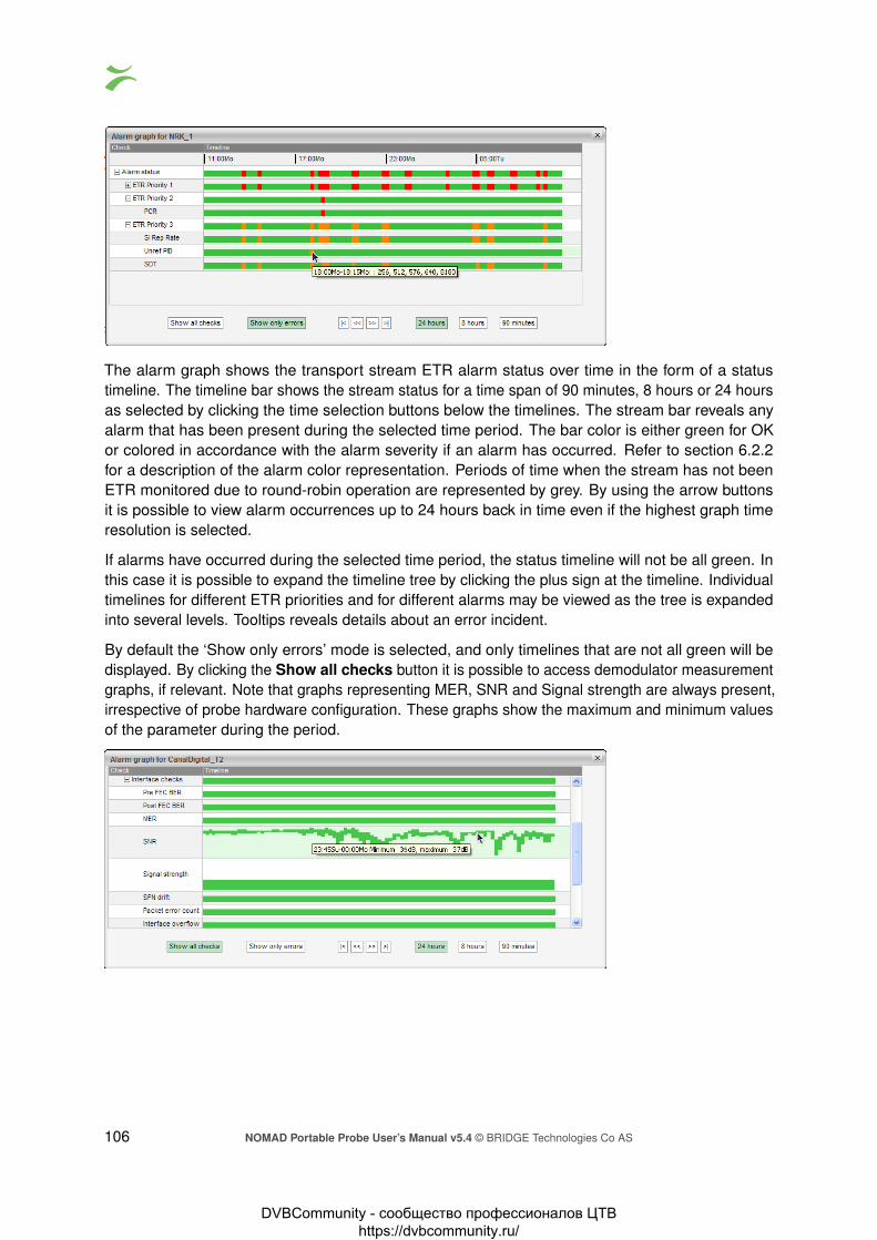
The alarm graph shows the transport stream ETR alarm status over time in the form of a statustimeline. The timeline bar shows the stream status for a time span of 90 minutes, 8 hours or 24 hoursas selected by clicking the time selection buttons below the timelines. The stream bar reveals anyalarm that has been present during the selected time period. The bar color is either green for OKor colored in accordance with the alarm severity if an alarm has occurred. Refer to section 6.2.2for a description of the alarm color representation. Periods of time when the stream has not beenETR monitored due to round-robin operation are represented by grey. By using the arrow buttonsit is possible to view alarm occurrences up to 24 hours back in time even if the highest graph timeresolution is selected.
If alarms have occurred during the selected time period, the status timeline will not be all green. Inthis case it is possible to expand the timeline tree by clicking the plus sign at the timeline. Individualtimelines for different ETR priorities and for different alarms may be viewed as the tree is expandedinto several levels. Tooltips reveals details about an error incident.
By default the ‘Show only errors’ mode is selected, and only timelines that are not all green will bedisplayed. By clicking the Show all checks button it is possible to access demodulator measurementgraphs, if relevant. Note that graphs representing MER, SNR and Signal strength are always present,irrespective of probe hardware configuration. These graphs show the maximum and minimum valuesof the parameter during the period.
106 NOMAD Portable Probe User’s Manual v5.4 © BRIDGE Technologies Co AS
DVBCommunity - cообщество профессионалов ЦТВ https://dvbcommunity.ru/

6.9.3 ETR 290 — PIDs
This view lists the PIDs of the currently active stream of the selected input. The PID list can be sortedby clicking a table column header.
The name of the current stream is displayed in addition to the two round-robin indicator icons whenrelevant: the time cycle icon and the lock icon. By clicking the lock icon the round-robin cycling isstopped or resumed. A DVB or ATSC icon indicates the analysis mode. The analysis mode is definedas part of the ETR thresholds.
By clicking the button Clear counters the minimum and maximum bitrates and the CC error counterswill be reset. Note that this cannot be undone.
When clicking the blue information icon associated with a PID details concerning that PID will bedisplayed. All services referring to the PID are listed, and scrambling information is shown.
The following PID details are displayed:
PID Details:PID: The PID for which the following parameters apply
Current bitrate: The current bitrate measurement for this PID. The bitrate is averagedover 1 second.
NOMAD Portable Probe User’s Manual v5.4 © BRIDGE Technologies Co AS 107
DVBCommunity - cообщество профессионалов ЦТВ https://dvbcommunity.ru/

Minimum bitrate: The minimum bitrate measurement for this PID since the start of themonitoring period. (I.e. when the probe tuned to the frequency or whenthe monitoring of this frequency was restarted by the user clicking on‘Clear status’ in the ‘ETR Overview’.)
Maximum bitrate: The maximum bitrate measurement for this PID since the start of themonitoring period.
Carries PCR: If the PID carries Program Clock Reference information, this field will beset to Yes. If PCR analysis is enabled in the ETR threshold template alink will be shown to bring up the PCR histogram data for this PID.
Scrambling: If the PID is scrambled, this field will show if it is scrambled with Odd orEven control word.
Number of CC errors: The number of CC errors for the specified PID. For the Ethernet interfacethe number of CC errors is measured from when the probe started tomonitor the multicast or when the user clicked ‘Clear counters’ in the‘Mon’ page.
References: All the references for this PID in the PSI/SI/PSIP tables. This will showthe reference type and the service that refers the PID (if applicable). Theservice can be clicked to show the detailed service information.
6.9.4 ETR 290 — Services
The ETR290 — Services view lists the services and service components of the current stream ofthe selected input.
The name of the current stream is displayed in addition to the two round-robin indicator icons whenrelevant: the time cycle icon and the lock icon. By clicking the lock icon, the round-robin cycling isstopped or resumed. A DVB or ATSC icon indicates the analysis mode. The analysis mode is definedas part of the ETR thresholds.
When tree nodes are selected, detailed information will be displayed on the right hand side of theview.
If the service tree ‘Services’ top node is clicked, a summary list of stream services and PIDs isdisplayed. Each service’s service ID and each component’s PID value and bitrate are displayedtogether with individual PID and service bitrates.
108 NOMAD Portable Probe User’s Manual v5.4 © BRIDGE Technologies Co AS
DVBCommunity - cообщество профессионалов ЦТВ https://dvbcommunity.ru/
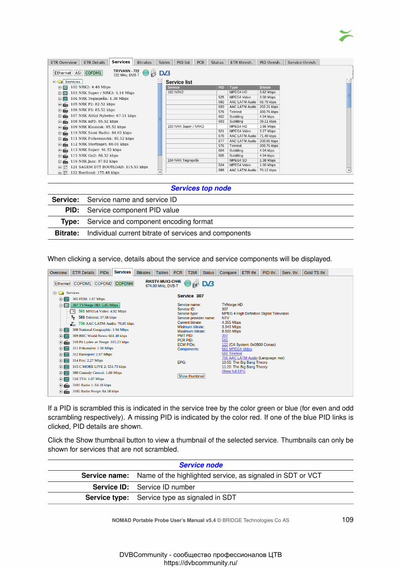
Services top node
Service: Service name and service IDPID: Service component PID value
Type: Service and component encoding format
Bitrate: Individual current bitrate of services and components
When clicking a service, details about the service and service components will be displayed.
If a PID is scrambled this is indicated in the service tree by the color green or blue (for even and oddscrambling respectively). A missing PID is indicated by the color red. If one of the blue PID links isclicked, PID details are shown.
Click the Show thumbnail button to view a thumbnail of the selected service. Thumbnails can only beshown for services that are not scrambled.
Service nodeService name: Name of the highlighted service, as signaled in SDT or VCT
Service ID: Service ID numberService type: Service type as signaled in SDT
NOMAD Portable Probe User’s Manual v5.4 © BRIDGE Technologies Co AS 109
DVBCommunity - cообщество профессионалов ЦТВ https://dvbcommunity.ru/

Service provider name: The name of the service provider as signaled in SDT. Not applicablefor ATSC streams.
Current bitrate: The current bitrate measurement for this service. The bitrate is aver-aged over 1 second.
Minimum bitrate: The minimum bitrate measurement for this service since the start ofthe monitoring period. (I.e. when the probe tuned to the frequencyor when the monitoring of this frequency was restarted by the userclicking on ‘Clear status’ in the ‘ETR Overview’.)
Maximum bitrate: The maximum bitrate measurement for this service since the start ofthe monitoring period.
PMT PID: The service’s PMT PIDPCR PID: The service’s PCR PID
ECM PIDs: The service’s ECM PID(s) and name of CA system(s). This infor-mation will only be displayed if ECM PIDs are signaled in the PMTtable, usually only done when one or more service components arescrambled.
Components: A list of the component PIDs and reference types. For PIDs whichhave a language descriptor (typically audio PIDs) the language codeis also shown.
EPG: If DVB EIT is present in the stream and EIT table IDs are configuredin the Setup — ETR view, EIT present/following is displayed. If EITschedule is present in the stream, a blue ‘Show full EPG’ link is dis-played. By clicking the link it is possible to view the EIT scheduleinformation.
Show thumbnail Opens the Thumbnail view for this service. For demodulator andASI inputs, thumbnails are only decoded automatically if the Extractthumbnails option has been enabled in the associated tuning setup,or if content check alarming (Content Extraction and Alarming option)has been enabled in the ETR threshold template. Please note initialextraction of thumbnails can take around one minute when decodingthe thumbnail manually by opening this pop-up.
When clicking a service component, associated key parameters and references will be displayed.
110 NOMAD Portable Probe User’s Manual v5.4 © BRIDGE Technologies Co AS
DVBCommunity - cообщество профессионалов ЦТВ https://dvbcommunity.ru/

For PIDs carrying PCR it is possible to view a PCR jitter histogram by clicking the blue ‘showhistogram’ link. If one of the blue service links is clicked, service details are shown.
Service component node
Current bitrate: The current bitrate measurement for this component. The bitrate isaveraged over 1 second.
Minimum bitrate: The minimum bitrate measurement for this component since the startof the monitoring period. (I.e. when the probe tuned to the frequency orwhen the monitoring of this frequency was restarted by the user clickingon ‘Clear status’ in the ‘ETR Overview’.)
Maximum bitrate: The maximum bitrate measurement for this component since the start ofthe monitoring period.
Carries PCR: An indication of whether the PID carries PCR or not. The value maybe ‘Yes’ or ‘No’. If PCR is carried by the PID, a blue ‘show histogram’link is displayed. By clicking this link it is possible to view the PCR jitterhistogram.
Scrambling: An indication of whether the PID is scrambled or not. If the PID is notscrambled, the value will be ‘No’. If the PID is scrambled, informationabout the current control word is displayed: ‘Even 0x3’ or ‘Odd 0x2’.
Number of CC errors: The number of CC errors detected during the monitoring period
References: A list of PSI/SI references to the component PID. When one of the blueservice links is clicked, detailed service information is displayed.
NOMAD Portable Probe User’s Manual v5.4 © BRIDGE Technologies Co AS 111
DVBCommunity - cообщество профессионалов ЦТВ https://dvbcommunity.ru/

6.9.5 ETR 290 — Bitrates
This view shows a graphical representation of service and PID bitrates. The current bitrate is shownas the length of the light blue bar whereas the dark blue bar represents bitrate variation, spanningfrom minimum to maximum measured bitrate.
The name of the current stream is displayed in addition to the two round-robin indicator icons whenrelevant: the time cycle icon and the lock icon. By clicking the lock icon the round-robin tuning processis stopped (locked to the current frequency) or resumed. A DVB or ATSC icon indicates the analysismode. The analysis mode is defined as part of the ETR thresholds.
The user may select to view either a list of services and component PIDs, to view PIDs only or toview PIDs without the null PID. This is selected by clicking the Show Services, Show only PIDs orShow only PIDs but not NULL PID button respectively.
112 NOMAD Portable Probe User’s Manual v5.4 © BRIDGE Technologies Co AS
DVBCommunity - cообщество профессионалов ЦТВ https://dvbcommunity.ru/

6.9.6 ETR 290 — Tables
This view lists the PSI and SI or ATSC tables and table contents of the currently active stream of theselected input.
The name of the current stream is displayed in addition to the two round-robin indicator icons whenrelevant: the time cycle icon and the lock icon. By clicking the lock icon the round-robin cycling isstopped or resumed. A DVB or ATSC icon indicates the analysis mode. The analysis mode is definedas part of the ETR thresholds.
Clicking the ‘Sections’ node displays detected tables and associated repetition rates.
Clicking a table enables viewing the table contents in a readily readable format.
By clicking the plus-icon at a table the table contents is displayed in detail.
Clicking one of the table entries will allow viewing the table contents as a hexadecimal dump fordetailed inspection.
NOMAD Portable Probe User’s Manual v5.4 © BRIDGE Technologies Co AS 113
DVBCommunity - cообщество профессионалов ЦТВ https://dvbcommunity.ru/

The selected table entry is highlighted in the table dump. Note that values shown in the table list maynot correspond directly to the highlighted hex dump byte(s), because some of the table entries do notadd up to whole bytes.
By hovering the cursor over the items in the tree a tooltip is displayed showing the start position ofthe data in the hexadecimal dump and the length of data. Press the save icon to download and savethe raw table data on your computer.
A description of each PSI/SI table is beyond the scope of this manual, please refer to the specificationsfor more information about PSI/SI.
For streams which have electronic program guide information in the EIT table and the extractionof this information is enabled (in ETR thresholds and in Setup — ETR) the tree will show the textEIT. Clicking on this will bring up the list of present/following events (the current program and thenext program to be broadcast) for the current stream will be displayed. If the stream has EIT p/fother information (and this table is enabled in Setup — ETR) then the list will also contain EPGpresent/following for other streams. If the stream has EIT schedule information for the actual and/or
114 NOMAD Portable Probe User’s Manual v5.4 © BRIDGE Technologies Co AS
DVBCommunity - cообщество профессионалов ЦТВ https://dvbcommunity.ru/

other streams (and these tables are enabled in Setup — ETR) then the list will also contain thelink Show EIT schedule. Clicking this will show the full schedule for the selected service. Theamount of data shown depends on the signal. A common practice is to send EPG for 7 days ahead.
6.9.7 ETR 290 — PCR
The PCR jitter histogram displays PCR jitter as measured by the probe. A list of detected PCR PIDsin the selected stream is shown together with their current and maximum PCR jitter values. A PCRPID is selected for histogram presentation by clicking the associated table entry. The histogramshows the number of received PCR values versus jitter. PCR jitter is by default measured as PCR-ACfor all interfaces. By creating an ETR threshold template that enables PCR-OJ and assigning thistemplate to a stream it is possible to select PCR-OJ measurement mode by clicking the PCR_OJbutton. The PCR_OJ measurement is not relevant for Ethernet streams.
Please note PCR analysis will be disabled if neither PCR-AC, PCR-OJ and the PCR Accuracy andPCR Jitter checks are enabled in the ETR thresholds. So to use the ETR 290 — PCR functionalitythis needs to be enabled.
NOMAD Portable Probe User’s Manual v5.4 © BRIDGE Technologies Co AS 115
DVBCommunity - cообщество профессионалов ЦТВ https://dvbcommunity.ru/

The name of the current stream is displayed in addition to the two round-robin indicator icons whenrelevant: the time cycle icon and the lock icon. By clicking the lock icon the round-robin cycling isstopped or resumed. The pushbuttons Zoom in and Zoom out enables rescaling of the graph. Thismakes it possible to view PCR jitter values that are outside the range defined by the auto-scaling.Clicking the Clear button will clear historical data from the histogram.
Tooltip functionality provides information about each histogram bar: the number of samples, thepercentage of total number of samples and the jitter interval represented by the bar. For PCRmeasurements to be valid it is essential that the signal be stuffed with null packets (PID 8191) toobtain an absolutely constant bitrate. The stream info above the histogram shows if the analyzedstream contains null packets or not. A color indicator above the PCR jitter histogram indicates whetherthe signal is of constant bitrate or not, as perceived by the PCR filter in the processing engine. Greenindicates OK, red indicates that the PCR jitter measurements are not valid due to the bitrate not beingconstant.
Note that PCR jitter measurements for Ethernet streams are very sensitive to packet loss, and packetloss results in a large jitter values – often for all PCR PIDs of an MPTS.
The PCR PID list displays the following parameters:
PID: The PID for which the following parameters apply.
Current: The last PCR jitter value measured.
Overall max: The maximum PCR jitter value measured since transport stream sync was ob-tained. Note that this may not correspond to the maximum value for PCR jitter inthe histogram, as the histogram displays values measured from the time when aPCR PID was selected.
Threshold: The PCR jitter threshold currently valid for the stream, as defined in the associatedETR threshold template.
In addition to the histogram itself, the following parameters are displayed:
Max jitter (ns): The maximum jitter value measured from the time the PID was selected.
Average jitter (ns): The average jitter in nanoseconds.
Bin resolution (ns): The width of the jitter interval spanned by each histogram bar.
Outside thresholds: The number of PCR values that are outside the PCR jitter thresholds(defined by the user as part of the ETR threshold template).
Out of view: The number of PCR values that are out of the currently displayed view.
116 NOMAD Portable Probe User’s Manual v5.4 © BRIDGE Technologies Co AS
DVBCommunity - cообщество профессионалов ЦТВ https://dvbcommunity.ru/

6.9.8 ETR 290 — T2MI (requires T2MI-OPT)
T2MI monitoring is a licensing option available for transport streams over ASI and Ethernet. T2MI isenabled on a per stream basis, most of the information is found in this GUI extracted from the L1current packets in the T2MI streams. The full parsing of this information table is found in the ‘Tables’section.
Please note that the T2MI stream needs to have either a relative or an absolute T2 Timestamp to bereceived properly. Signals without timing information can not be received.
Overview:T2 timestamp: The last received T2 timestamp. The probe supports both rela-
tive and absolute timestamps.
Super frame index: The last received superframe index.
Frame index: The index of the last received frame.Input streams: Indicates whether Single or Multiple Input Streams are used.
Coding and modulation: Whether the stream uses Constant Coding and Modulation orAdaptive Coding and Modulation.
Input stream sync: The Input Stream Synchronizer (ISSY) value.
Input stream format: The format of the input stream. Will normally be ‘TS’.
Input stream identifier: The input stream identifier for the current stream.
Num TS pkt. last T2MI frame: The number of transport stream packets that was in the lastT2MI frame.
Null packet deletion: Whether null packet deletion is in use or not.
High efficiency mode: Whether high efficiency mode is active or not.
Crc Errors BB header: The number of CRC errors on the BB header detected since themonitoring of the stream started.
Crc Errors whole packet: The number of CRC errors calculated over the whole T2MIpacket since the monitoring of the stream started.
NOMAD Portable Probe User’s Manual v5.4 © BRIDGE Technologies Co AS 117
DVBCommunity - cообщество профессионалов ЦТВ https://dvbcommunity.ru/

L1 information:T2 version: The version of the T2 spec used. Up to version 1.3.1 is supported
including T2 lite.
Type: The type of data carried in the Transport stream.
T2 lite profile used: Set to true if the T2 lite profile is used for sending power efficient broad-casts to portable clients.
BW ext: The carrier mode (normal or extended).
S1: T2-SISO, T2-MISO or Non-T2.
S2: FFT mode and guard interval.
PAPR: The PAPR reduction mode (if any).
Pilot pattern: Pilot pattern PP1 to PP8.
TX ID availability: Should always be set to ‘No transmitter identification signals are used’.
Cell id: The cell ID for the transmitter.Network id: The network id for this DVB-T2 network.
T2 system id: The T2 system id.
L1 post scrambling: Says whether post scrambling is used or not.
L1 modulation: The L1 modulation type used. BPSK, QPSK, 16-QAM or 64-QAM.
L1 FEC type: The L1 fec type in use. Only ‘LDPC 16K’ is currently supported inDVB-T2.
L1 repetition: Shows if dynamic signaling is provided.
L1 post size: The L1 post size.
L1 post info size: The L1 post info size.
L1 post extension: Shows if extension field is provided.
L1 change counter: The value of the L1 change counter.
Guard interval: The guard interval used for the transmission. 1/32, 1/16, 1/8 or 1/4.
Num T2 frames: The number of T2 frames signaled.
Num data symbols: The number of data symbols signaled.
Sub slices per frame: How many sub slices are used per T2 frame.
Num aux: The number of auxiliary channels transmitted.
Aux config rfu: The aux config rfu number.
Number of RF: The number of RF frequencies used to transmit the signal.
Frequencies: The list of frequencies used to transmit the signal. Normally only onefrequency will be used.
Current RF index: The index of the frequency currently being used for the transmission.
Start RF idx: The starting RF index.
Frame idx: The frame index.Sub slice interval: The interval between sub slices.
Type 2 start: The value of the type 2 start parameter.
Regen flag: The value of the regen flag.
118 NOMAD Portable Probe User’s Manual v5.4 © BRIDGE Technologies Co AS
DVBCommunity - cообщество профессионалов ЦТВ https://dvbcommunity.ru/

PLP (Physical Layer Pipes) information:
Current PLP: The PLP currently being received. If a specific PLP was configured the interfacesettings T2MI extraction (ASI — Setup or Multicasts — Streams), this will beused. If auto mode is used the first PLP detected will be used.
Detected PLPs: The detected PLP ids in the T2MI stream. In some error situations this maydiffer from the list of Signaled PLPs show below.
Signaled PLPs: Lists the PLPs signaled in the stream.
PLP type: The signaled type of the PLP. Data PLP Type 1 is the most common, somesignals can have a common PLP as well as well as other PLP types.
Payload: Payload type of this PLP. Will typically be the Transport Stream format
PLP Group: The group signaled for this PLP. The PLPs in a group shares one commonPLP and when analyzing a PLP both the data in the specified PLP and thecommon PLP in the same group (if present) are extracted. The PLP containsPIDs which are shared such as PAT, SDT, NIT, CAT and EMMs. In the exampleabove , analyzing PLP 0 will also analyze PLP 2.
Code: The FEC coding scheme used for this PLP.
Modulation: Modulation for the the PLP.Rotation: Specifies if IQ rotation is enabled.
FEC: Specifies the FEC coding type for this PLP.
Clicking the blue information symbol in the PLP list will bring up more detailed information for thatPLP.
Detailed PLP information:PLP: The ID of the signaled PLP.
Type: The signaled type of the PLP. Data PLP Type 1 is the most common,some signals can have a common PLP as well as well as other PLPtypes.
NOMAD Portable Probe User’s Manual v5.4 © BRIDGE Technologies Co AS 119
DVBCommunity - cообщество профессионалов ЦТВ https://dvbcommunity.ru/

Payload: Payload type of this PLP. Will typically be the Transport Stream format
FF flag: The FF flag value.
First RF idx: The first first RF index used for transmitting this PLP.
First frame idx: The first frame index used to transmit this PLP.PLP group id: The group signaled for this PLP. The PLPs in a group shares one
common PLP and when analyzing a PLP both the data in the specifiedPLP and the common PLP in the same group (if present) are extracted.The PLP contains PID which are shared such as PAT, SDT, NIT, CATand EMMs.
Coding: The FEC coding scheme used for this PLP.
Modulation: Modulation used for transmitting this PLP.
Rotation: Specifies if IQ rotation is enabled for this PLP.
FEC type: Specifies the FEC coding type for this PLP.
PLP num blocks max: The maximum number of blocks which can be used by this PLP.
Frame interval: The frame interval for this PLP.Time IL length: The length of the time interleaver.
Time IL type: The time interleaving type in use.
In band A: Says if in-band type A signaling is used for this PLP.
In band B: Says if in-band type B signaling is used for this PLP.
PLP mode: The PLP mode for this PLP.Static: Says whether the PLP bandwidth is static or not static.
Static padding: Says whether the padding is static or can change between each BBframe.
PLP start: The start value for the PLP in the stream.PLP num blocks: The number of blocks used for this PLP.
120 NOMAD Portable Probe User’s Manual v5.4 © BRIDGE Technologies Co AS
DVBCommunity - cообщество профессионалов ЦТВ https://dvbcommunity.ru/

6.9.9 ETR 290 — SCTE 35 (requires SCTE35-OPT)
SCTE 35 is a specification which allows equipment to splice in local content at specific times, SCTE35 is basically just the signaling mechanism the equipment uses to know when to switch from themaster transmission to insert local content. It can be used to allow insertion of local advertising atcertain points in time or to allow the local operator to insert their own programs such as local newstransmission.
SCTE 35 requires a license for the probe and also an ETR 290 engine to connect it to.
The SCTE 35 option enables monitoring of SCTE 35 events of all streams captured by the ETRengines. It is recommended to one ETR engine dedicated to each SCTE 35 streams to get continuousmonitoring.
The stream list parameters
Stream name: Name specified by the user when adding a multicast or tuning.
Interface: The input source of the transport stream.
Services incl. SCTE 35: The number of services in the transport stream which has SCTE 35information.
Events: The number of SCTE 35 events occurred in a transport stream.
Time since last event: The time since last SCTE 35 event specified in seconds, minutes,hours or days.
If an ETR engine is monitoring a transport stream containing SCTE 35 information, the current streamwill be added to the list in the SCTE 35 menu. By pressing the blue information button a new pop-upwill show up, the pop-up will give specific information about events in the specified transport stream.
The event information list parameters:
NOMAD Portable Probe User’s Manual v5.4 © BRIDGE Technologies Co AS 121
DVBCommunity - cообщество профессионалов ЦТВ https://dvbcommunity.ru/

Parameter Description
Time: When the event occurred.Service ID: The ID of the service for which the event applies.
Service name: The name of the service for which the event applies.
PID: The PID carrying the SCTE 35 information. A service can have multipleSCTE 35 PIDs signaled in the PMT table.
Splice command: The type of the splice command.
Event ID: Id of the specific event.
Canceled indicator: If set it indicates that this splice message cancels a previously sent splicemessage.
Switch mode: Specifies whether it is a splice in (switch to local content/ads) or splice outevent (switch back to the audio/video in the stream).
Splice mode: Specifies whether the splice message applies to the entire service (Pro-gram splice mode) or individual PID(s).
Duration: The time when a splice occurred to its end.
Tier: Specifies which tier group are to use this splice message. Multiple splicemessages can be sent addressed to different tier groups to allow switchingat different times.
When pressing the information button for a specific event a new window will pop-up with detailedinformation about the event. The pop-up will show a log of the SCTE 35 events signaled for thespecified transport stream. Splice NULL messages are not logged.
122 NOMAD Portable Probe User’s Manual v5.4 © BRIDGE Technologies Co AS
DVBCommunity - cообщество профессионалов ЦТВ https://dvbcommunity.ru/

6.9.10 ETR 290 — Status
The ETR 290 — Status view shows a stream content overview linked to current alarms, making iteasy to view what services and PIDs are currently affected by errors.
By clicking any of the ‘view’, service or PID nodes, more information will be displayed on the righthand side of the table. This information is described in ETR 290 — Services.
6.9.11 ETR 290 — Compare
The Compare view is based on analysis performed by the ETSI TR 101 290 engine and will only bevisible if the probe is licensed with the ETR 290 option.
The Compare view allows comparison of services or transport streams across different probeinterfaces. Clicking Show streams results in a list of selectable transport streams and services, andclicking Show services results in a list of selectable services. For a transport stream to be selectableit must be ETR monitored. Note that the screen is not auto-refreshed, click the Compare tab toperform an active refresh.
NOMAD Portable Probe User’s Manual v5.4 © BRIDGE Technologies Co AS 123
DVBCommunity - cообщество профессионалов ЦТВ https://dvbcommunity.ru/

One or more services or transport streams are selected by clicking and later Ctrl + clicking items fromthe list. Clicking the Compare selected button will launch a condensed overview page that allowsstatus parameters for services or streams to be viewed side by side. Key parameters are presentedin one column for each service/stream, and it is easy to recognize differences in signal contents oralarm status. The number of streams that can be compared depends on screen size.
The compare column consists of several sub-views:
Stream overview
124 NOMAD Portable Probe User’s Manual v5.4 © BRIDGE Technologies Co AS
DVBCommunity - cообщество профессионалов ЦТВ https://dvbcommunity.ru/

Stream overview shows a number of key parameters for the selected stream/service.
Stream overviewTS ID: The transport stream ID of the selected stream or the stream containing the
selected serviceNW ID: The network ID of the selected stream or the stream containing the selected
serviceOrig NW ID: The original network ID of the selected stream or the stream containing the
selected serviceMin. eff. bitr: The minimum effective bitrate (null packets removed) measured for the selected
stream or the stream containing the selected service
Max. eff. bitr: The maximum effective bitrate (null packets removed) measured for the selectedstream or the stream containing the selected service
Min. tot. bitr: The minimum total bitrate (including null packets) measured for the selectedstream or the stream containing the selected service
Max. tot. bitr: The maximum total bitrate (including null packets) measured for the selectedstream or the stream containing the selected service
Last update: The time since the last update. The information will be updated when the roundrobin ETR engine stops monitoring a stream or once every minute for streamswhich are permanently monitored.
Error statisticsTotal monitoring time: The total time the stream has been monitored by the ETR engine
ETR Priority 1: The time the stream has been affected by ETSI TR 101 290 Priority 1errors
ETR Priority 2: The time the stream has been affected by ETSI TR 101 290 Priority 2errors
ETR Priority 3: The time the stream has been affected by ETSI TR 101 290 Priority 3errors
No signal: The time the stream has been affected by ‘No signal’ alarm
CC errors: The time the stream has been affected by ‘CC error’ alarm
Interface errors: The time the stream has been affected by ‘Interface error’ alarm
Other checks: The time the stream has been affected by miscellaneous ‘Other’ alarms
Pie charts indicate for how long the stream has been affected by errors compared to the totalmonitoring time, green color representing ‘OK’ and red color ‘Error’.
NOMAD Portable Probe User’s Manual v5.4 © BRIDGE Technologies Co AS 125
DVBCommunity - cообщество профессионалов ЦТВ https://dvbcommunity.ru/

Service alarm
If a transport stream is selected for comparison the Service alarms subview displays a list of servicespresent in the stream. If there is one or more active alarms for a service this will be indicated by a red‘bulb’ whereas a green ‘bulb’ indicates no active alarms. If a service is affected by one or more activealarms these alarms may be viewed by expanding the service tree. If relevant the PIDs affectedby alarms are also displayed. Note that only alarms detected during the last monitoring period aredisplayed.
If a service is selected for comparison this subview simply shows the selected service and any activealarms affecting the service.
Services
If a transport stream is selected for comparison the Services subview displays a list of servicespresent in the stream. Clicking the plus icon at a service will expand the service tree, displaying the ser-vice’s individual components. The minimum and maximum effective bitrates of a service/componentare also shown, in addition to the number of continuity counter errors and the maximum measuredPCR jitter (if relevant).
Colored PIDs indicate scrambling; blue and green representing odd and even scrambling respectively.
Note that all references to a PID will result in a PID entry, i.e. one PID may be displayed several timesin the list.
Alarm graph
126 NOMAD Portable Probe User’s Manual v5.4 © BRIDGE Technologies Co AS
DVBCommunity - cообщество профессионалов ЦТВ https://dvbcommunity.ru/

The Alarm graph subview shows similar alarm graphs as the ETR 290 — ETR Details — Alarmgraph popup view. Please refer to the ETR 290 — ETR Details section of this User’s Manual for acomprehensive description of this view.
ETR Details
The ETR details subview shows the same alarm overview as the ETR 290 — ETR Details view.Clicking a check will open a pop-up view displaying alarm details. Please refer to the ETR 290 —ETR Details section of this user’s manual for a comprehensive description of this view.
NOMAD Portable Probe User’s Manual v5.4 © BRIDGE Technologies Co AS 127
DVBCommunity - cообщество профессионалов ЦТВ https://dvbcommunity.ru/

6.9.12 ETR 290 — ETR threshold
The ETR thresholds make it possible to define detailed conditions for ETR 290 alarm triggering ona per-stream basis. There are seven predefined ETR threshold templates that are write-protectedand cannot be edited by the operator:
• Default
• ETSI TR 101 290
• ATSC Default
• Optimised
• IP-SPTS
• CMTS downlink
• Analog carrier
These predefined thresholds may be used when defining a monitoring configuration, but it is a goodidea to create editable copies of these threshold templates and use these copies rather than theoriginals. Doing so will allow fine-tuning of parameters later on.
There are two different ways of creating user-defined thresholds. To create a new threshold templatefrom scratch the operator should click the Add new threshold button. A pop-up window will appearallowing the user to define alarm conditions and set the round-robin cycling time. The default values ofthe different parameters settings are in accordance with the ETSI TR 101 290 specification. Anotherway of creating a user-defined threshold template is by highlighting one of the threshold templatesalready defined and then click the Duplicate highlighted button. The copy created this way may beedited during the fine-tuning phase of system configuration.
Deleting an ETR threshold template is done by highlighting the threshold template that should beremoved and clicking Delete highlighted. Note that if the deleted threshold template is assigned toa stream currently being monitored, the new threshold for that stream will default to the predefinedDefault threshold template.
It is possible to perform multi-editing of existing threshold templates by selecting several thresholdtemplates (using the regular Ctrl + click or Shift + click functionality) and clicking Edit selected.
128 NOMAD Portable Probe User’s Manual v5.4 © BRIDGE Technologies Co AS
DVBCommunity - cообщество профессионалов ЦТВ https://dvbcommunity.ru/

Parameters that differ between the threshold templates will be represented by an asterisk in the EditETR threshold view. Changes made will affect all selected threshold templates.
The ETR threshold template has the following settings:
ETR Thresholds — Parameters:Name: A text field with the name of the ETR threshold template
Description: Text field that should contain a meaningful description of the threshold
Analysing Mode: The mode of table analysis. DVB or ATSC may be selected.
Error timeout (s): The number of seconds an alarm stays active before it is cleared, if nonew alarms are generated. For all table related alarms the actual alarmtimeout used is the sum of the Error timeout parameter and the maximumtable repetition period. E.g. the TDT (Time Date Table) with table repetitionset to 30 seconds will have an effective error timeout of 40 seconds. Thisavoids toggling of alarms for tables that are sent infrequently. Defaultvalue: 10 s
NOMAD Portable Probe User’s Manual v5.4 © BRIDGE Technologies Co AS 129
DVBCommunity - cообщество профессионалов ЦТВ https://dvbcommunity.ru/

Tuning duration (s): The time (in seconds) the probe will stay tuned to a frequency/multicastduring the round-robin loop. For setting the tuning duration, use thefollowing expression: max_table_rep*2 + 10Use the maximum table repetition, multiply it by 2 and then add 10 seconds.E.g. with TDT repetition set to 30 seconds, use 30*2+10=70 secondstuning duration.In order to speed up the tuning process tables should be transmittedmore frequently. For instance if TDT, which is usually the least frequentlytransmitted table, is sent every 10 seconds, a tuning duration of 30 secondsmay be used. For signals without TDT (common in SPTS) the TDT checkcan be disabled and the tuning duration may be reduced. If only RFmeasurements are performed, the minimum recommended tuning durationis 30 seconds. If the tuning duration is set too low the checks for tableswith long table repetition periods will still be in an unknown state as theprobe does not have enough measurements to determine the state forthese. Tuning duration should never be set to less than 10 seconds forEthernet streams and 15 seconds for all other streams (the minimum forRF steams depends on the setup). Default value: 70 s
Sync loss tuningduration (s):
The time (in seconds) the probe will stay tuned to a frequency/multicastwith TS Sync loss during the round-robin tuning process. Usually thereis no need to stay tuned to a frequency/multicast once the probe hasestablished that there is no signal on the tuning setup. When monitoring atuning setup with signal loss, the probe will use the lowest value of ‘Tuningduration’ and ‘Sync loss tuning duration’, e.g. if the former is set to 60seconds and the latter to 1000 seconds, 60 seconds will be used. Defaultvalue: 15 s
Minimum sectiongap (ms):
The minimum gap between transmission of two consecutive sections withthe same table ID. If the sections are transmitted too rapidly the STBmay not be able to process the data in time and various problems canoccur. However newer STBs can normally handle lower section gaps thanthe default value of 25ms. The section gap time is measured as the timebetween reception of the last TS packet of two consecutive (complete)sections. This section gap setting is used for PAT, PMT, CAT, NIT, RST,TDT, MGT, VCT, PIM/PNM, RRT, ATSC EIT, ETT and STT. There areseparate gap settings for SDT and EIT. Default value: 25 ms
ETR Thresholds — Priority 1:
TS sync: Enable or disable alarming of no signal error (TS sync loss)
Sync byte: Enable or disable alarming of sync byte errors
PAT: Enable or disable alarming of Program Association Table errors
PAT – Maximuminterval (ms):
The maximum allowed section repetition interval for the PAT table.Default: 500 ms
PAT – Minimumnumber of services:
The minimum number of services that must be present in the PAT.Set to 0 to disable this check. Default: 0
130 NOMAD Portable Probe User’s Manual v5.4 © BRIDGE Technologies Co AS
DVBCommunity - cообщество профессионалов ЦТВ https://dvbcommunity.ru/

PAT – AllowedTransport Stream IDs:
When this field is left blank all TS IDs are considered valid. If one ormore TS IDs are specified (separated by commas or as a range) onlythese IDs are considered valid, and any other TS ID will trigger analarm. Example of a valid field: ‘100-120, 300,320’
Continuity: Enable or disable alarming of Continuity Counter errors
PMT: Enable or disable alarming of Program Map Table errors
PMT – Maximuminterval (ms):
The maximum allowed section repetition interval for the PMT tables.Default: 500 ms
PMT – Minimumnumber of components:
The minimum number of components that must be present in allservices. Set to 0 to disable this check. Default: 0
PMT – Requirelanguage descriptors:
If enabled it requires a language descriptor to be present for all audiocomponents signaled in the PMT. Default: Disabled
Missing PID: Enable or disable alarming of missing PID errors
Note that errors affecting individual PIDs may be effectively masked by creating suitable PID thresholdtemplates that are associated with these PIDs. This is particularly useful for PIDs affected bycontinuity counter errors, missing PID errors and unreferenced PID errors.
ETR Thresholds — Priority 2:
Transport: Enable or disable alarming of Transport error indicator errors
CRC: Enable or disable alarming of checksum errors for tables
PCR: Enable or disable alarming of Program Clock Reference errors
PCR – Maximuminterval (ms):
The maximum interval between reception of PCR values. Default:40 ms
PCR – Minimuminterval (ms):
The minimum interval between reception of PCR values. Normallythis setting should be 0. Default: 0 ms
PCR – Discontinuitythreshold (ms):
The maximum change in the PCR value between two adjoiningPCR values (where the discontinuity indicator flag has not beenset). Default: 100 ms
PCR – Requirepresence of PCR:
When enabled an alarm will be raised if a PID signaled as PCR inthe PMT does not carry PCR information
PCR Accuracy: Enable or disable alarming of PCR Accuracy (PCR Jitter) errorsfor OCR_AJ and PCR_OJ. PCR_OJ is not relevant for Ethernetstreams.
PCR Accuracy – MaximumPCR_AC jitter (ns):
The maximum allowed PCR jitter for PCR_AC measurements. De-fault: 500 ns
PCR Accuracy – MaximumPCR_OJ jitter (ns):
The maximum allowed PCR jitter for PCR_OJ measurements.PCR_OJ measurement does not apply to IP streams. Default:500 ns
NOMAD Portable Probe User’s Manual v5.4 © BRIDGE Technologies Co AS 131
DVBCommunity - cообщество профессионалов ЦТВ https://dvbcommunity.ru/
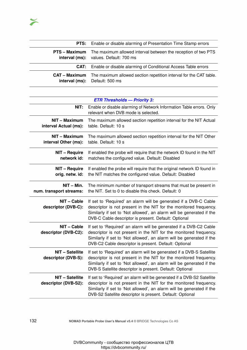
PTS: Enable or disable alarming of Presentation Time Stamp errors
PTS – Maximuminterval (ms):
The maximum allowed interval between the reception of two PTSvalues. Default: 700 ms
CAT: Enable or disable alarming of Conditional Access Table errors
CAT – Maximuminterval (ms):
The maximum allowed section repetition interval for the CAT table.Default: 500 ms
ETR Thresholds — Priority 3:
NIT: Enable or disable alarming of Network Information Table errors. Onlyrelevant when DVB mode is selected.
NIT – Maximuminterval Actual (ms):
The maximum allowed section repetition interval for the NIT Actualtable. Default: 10 s
NIT – Maximuminterval Other (ms):
The maximum allowed section repetition interval for the NIT Othertable. Default: 10 s
NIT – Requirenetwork id:
If enabled the probe will require that the network ID found in the NITmatches the configured value. Default: Disabled
NIT – Requireorig. netw. id:
If enabled the probe will require that the original network ID found inthe NIT matches the configured value. Default: Disabled
NIT – Min.num. transport streams:
The minimum number of transport streams that must be present inthe NIT. Set to 0 to disable this check. Default: 0
NIT – Cabledescriptor (DVB-C):
If set to ‘Required’ an alarm will be generated if a DVB-C Cabledescriptor is not present in the NIT for the monitored frequency.Similarly if set to ‘Not allowed’, an alarm will be generated if theDVB-C Cable descriptor is present. Default: Optional
NIT – Cabledescriptor (DVB-C2):
If set to ‘Required’ an alarm will be generated if a DVB-C2 Cabledescriptor is not present in the NIT for the monitored frequency.Similarly if set to ‘Not allowed’, an alarm will be generated if theDVB-C2 Cable descriptor is present. Default: Optional
NIT – Satellitedescriptor (DVB-S):
If set to ‘Required’ an alarm will be generated if a DVB-S Satellitedescriptor is not present in the NIT for the monitored frequency.Similarly if set to ‘Not allowed’, an alarm will be generated if theDVB-S Satellite descriptor is present. Default: Optional
NIT – Satellitedescriptor (DVB-S2):
If set to ‘Required’ an alarm will be generated if a DVB-S2 Satellitedescriptor is not present in the NIT for the monitored frequency.Similarly if set to ‘Not allowed’, an alarm will be generated if theDVB-S2 Satellite descriptor is present. Default: Optional
132 NOMAD Portable Probe User’s Manual v5.4 © BRIDGE Technologies Co AS
DVBCommunity - cообщество профессионалов ЦТВ https://dvbcommunity.ru/

NIT – Terrestrialdescriptor (DVB-T):
If set to ‘Required’ an alarm will be generated if a DVB-T Terrestrialdescriptor is not present in the NIT for the monitored frequency.Similarly if set to ‘Not allowed’, an alarm will be generated if theDVB-T Terrestrial descriptor is present. Default: Optional
NIT – Terrestrialdescriptor (DVB-T2):
If set to ‘Required’ an alarm will be generated if a DVB-T2 Terrestrialdescriptor is not present in the NIT for the monitored frequency.Similarly if set to ‘Not allowed’, an alarm will be generated if theDVB-T2 Terrestrial descriptor is present. Default: Optional
NIT – Comparewith reference NIT:
If enabled the NIT will be compared with the NIT on the referencefrequency, and an alarm will be generated if a mismatch is found.The first frequency in the tuning list will be used as the referencefrequency. Both the CRC values of the different sections and thenumber of sections must be identical. Default: Disabled
SI Repetition Rate: Enable or disable alarming of SI Repetition Rate errors.
Unreferenced PID: Enable or disable alarming of Unreferenced PID errors. To maskUnreferenced PID alarms for a PID create a PID threshold templatewhere this error is masked.
SDT: Enable or disable alarming of Service Description Table errors. Onlyrelevant when DVB mode is selected.
SDT – Maximuminterval Actual (ms):
The maximum allowed section repetition interval for the SDT Actualtable. Default: 2 000 ms
SDT – Maximuminterval Other (ms):
The maximum allowed section repetition interval for the SDT Othertable.Default: 10 000 ms
SDT – Minimumgap interval (ms):
The minimum allowed section gap interval for the SDT table. Default:25 ms
SDT – VerifySDT against PAT:
If enabled an alarm will be generated if a service found in the PAT isnot listed in the SDT. Default: Disabled
SDT – Requireservice name:
If enabled an alarm will be generated if a service found in the PATdoes not have a service name or if the service name is empty.Default: Disabled
SDT – RequireBAT Presence:
If enabled an alarm will be generated if BAT is not present in thestream. Default: Disabled
EIT: Enable or disable alarming of Event Information Table errors. Onlyrelevant when DVB mode is selected.
EIT – Maximuminterval Actual (ms):
The maximum allowed section repetition interval for the EIT Actualtable. Default: 2 000 ms
EIT – Minimumgap interval (ms):
The minimum allowed section gap interval for the EIT tables. Default:25 ms
NOMAD Portable Probe User’s Manual v5.4 © BRIDGE Technologies Co AS 133
DVBCommunity - cообщество профессионалов ЦТВ https://dvbcommunity.ru/

EIT – RequiredTable IDs:
If one or more table IDs are specified an alarm will be generatedif these table IDs are not present in the stream on the EIT PID.Entries should be separated by commas, or a range may be specified.Example: ‘78,79,80-85’ Default: Disabled
EIT – Verify thatpresent event is
transmitted
If enabled, an alarm will be raised if one or more services don’t havea present event transmitted in the EIT (i.e. no EPG for the currentprogram)
EIT – Check validtime for present event
If enabled, an alarm will be raised if time signaled for the presentevent (the current program) is not correct. The maximum offset fromthe current time can be configured.
EIT – Maximum timingerror for present event(s)
The maximum timing error to allow for the present event. If thecurrent time is not inside the program start/stop times by this marginthen an alarm will be raised.
EIT – Verify thatfollowing event is
transmitted
If enabled, an alarm will be raised if one or more services don’t havea following event transmitted in the EIT (i.e. no EPG for the nextprogram)
RST: Enable or disable alarming of Running Status Table errors. Onlyrelevant when DVB mode is selected.
RST – Maximuminterval (ms):
The maximum allowed section repetition interval for the RST table.Default: 20 s
TDT: Enable or disable alarming of Time Date Table errors. Only relevantwhen DVB mode is selected.
TDT – Maximuminterval (ms):
The maximum allowed section repetition interval for the TDT andTOT tables. Default: 30 000 ms
TDT – RequireTOT presence:
Check this checkbox if TOT presence is required. Default: disabled
MGT: Enable or disable alarming of Master Guide Table errors. Onlyrelevant when ATSC mode is selected.
MGT – Maximuminterval (ms):
The maximum allowed section repetition interval for the MGT table.Default: 150ms
VCT: Enable or disable alarming of Virtual Channel Table errors. Onlyrelevant when ATSC mode is selected.
Require TVCT: Require presence of the Terrestrial Virtual Channel Table.
Require CVCT: Require presence of the Cable Virtual Channel Table.
VCT – Maximuminterval (ms):
The maximum allowed section repetition interval for the VCT table.Default: 400ms
PIM/PNM: Enable or disable alarming of Program Information Message andProgram Name Message tables. Only relevant when ATSC mode isselected.
134 NOMAD Portable Probe User’s Manual v5.4 © BRIDGE Technologies Co AS
DVBCommunity - cообщество профессионалов ЦТВ https://dvbcommunity.ru/

Require PIM: Require presence of the Program Information Message table.
Maximum intervalPIM (ms):
The maximum allowed section repetition interval for the PIM table.Default: 500ms
Require PNM: Require presence of the Program Name Message table.
Maximum intervalPNM (ms):
The maximum allowed section repetition interval for the PNM table.Default: 1000ms
RRT: Enable or disable alarming of Rating Region Table errors. Onlyrelevant when ATSC mode is selected.
RRT – Maximuminterval (ms):
The maximum allowed section repetition interval for the RRT table.Default: 30000ms
STT: Enable or disable alarming of System Time Table errors. Only rele-vant when ATSC mode is selected.
STT – Maximuminterval (ms):
The maximum allowed section repetition interval for the STT table.Default: 1000ms
ATSC EIT: Enable or disable alarming of ATSC Event Information Table errors.Only relevant when ATSC mode is selected.
ATSC EIT – Maximuminterval EIT–0 (ms):
The maximum allowed section repetition interval for the ATSC EIT–0table. Default: 500ms
ATSC EIT – Maximuminterval EIT–1 to
EIT–3 (ms):
The maximum allowed section repetition interval for the ATSC EIT–1to EIT–3 tables. Default: 5000ms
ATSC EIT – Maximuminterval EIT–4 to
EIT–127 (ms):
The maximum allowed section repetition interval for the ATSC EIT–4to EIT–127 tables. Default: 30000ms
ETT: Enable or disable alarming of Extended Text Table errors. Onlyrelevant when ATSC mode is selected.
ETT – Maximuminterval ETT–0 (ms):
The maximum allowed section repetition interval for the ATSC ETT–0table. Default: 2000ms
ETT – Maximuminterval ETT–1 to
ETT–3 (ms):
The maximum allowed section repetition interval for the ATSC ETT–1to ETT–3 tables. Default: 5000ms
ETT – Maximuminterval ETT–4 to
ETT–127 (ms):
The maximum allowed section repetition interval for the ATSC ETT–4to ETT–127 tables. Default: 30000ms
ETR Thresholds — Other checks:CA system checks: Enable or disable alarming of Conditional Access System errors.
NOMAD Portable Probe User’s Manual v5.4 © BRIDGE Technologies Co AS 135
DVBCommunity - cообщество профессионалов ЦТВ https://dvbcommunity.ru/

CA system checks –Maximum ECM
interval (ms):
The maximum allowed ECM repetition interval. Default: 500 ms
CA system checks –Maximum ECM
change period (ms):
The maximum time allowed between ECM changes. Default:25000ms
CA system checks –Minimum avg.
EMM bitrate (bps):
The minimum allowed average EMM bitrate. Default: 1000 bps
CA system checks –EMM bitrate average
period (s):
The averaging period used to calculate EMM bitrate. Note that theaverage period must be at least 20s less than the round-robin tuningperiod, e.g. with a round-robin tuning period of 70s the maximumEMM bitrate average period is 50s. Default: 10s
CA system checks –Maximum control word
period (ms):
The maximum allowed control word period (the maximum timethat can go by without a change in the scrambling control bits forscrambled PIDs). Default: 25 000 ms
PID minimumbitrate checks:
Enable or disable alarming of PID minimum bitrate. The bitrates areset in the PID threshold template.
PID maximumbitrate checks:
Enable or disable alarming of PID maximum bitrate. The bitratesare set in the PID threshold template.
PID checks: Enable or disable alarming of PID presence errors, scrambling/clearrequirements and PID type checks. The checks are set in the PIDthreshold template.
Service minimumbitrate checks:
Enable or disable alarming of service minimum bitrate errors. Re-quirements are specified in the service threshold template associ-ated with the stream.
Service maximumbitrate checks:
Enable or disable alarming of service maximum bitrate errors. Re-quirements are specified in the service threshold template associ-ated with the stream.
Service checks: Enable or disable alarming of service presence, scrambling/clearrequired, service type, service name and service ID errors. Require-ments are specified in the service threshold template associatedwith the stream.
Service checks –Only allow services listed
in service template:
Check this box to enable service ID checks against the service IDlist specified in the service threshold template associated with thestream.
MIP checks: Enable or disable alarming of errors related to the Megaframe Inser-tion Packet.
136 NOMAD Portable Probe User’s Manual v5.4 © BRIDGE Technologies Co AS
DVBCommunity - cообщество профессионалов ЦТВ https://dvbcommunity.ru/

MIP checks –Require presence of MIP:
Check this box to enable an alarm if the MIP table is missing for thestream.
MIP checks –Max MIP timing
error(µs):
The maximum MIP timing error before raising an alarm. The unit isµs. Default: 10 µs
Content check (Content Extraction and Alarming Option) Enable or disable alarmingof freeze-frame and color-freeze errors. Requirements are specifiedin the service threshold template associated with the stream.
Gold TS check: Enable or disable alarming for tables failing Gold TS referencechecking.
Gold TS check –Also check version
number and CRC:
When enabled an alarm will be raised for any change, including achange in the table version number and CRC.
Gold TS check –Verify PAT table:
Do verification of the PAT table against the stored reference PATtable.
Gold TS check –Verify PMT tables:
Do verification of the PMT tables against the stored reference PMTtables.
Gold TS check –Verify CAT table:
Do verification of the CAT table against the stored reference CATtable.
Gold TS check –Verify SDT actual table:
Do verification of the SDT actual table against the stored referenceSDT actual table.
Gold TS check –Verify SDT other tables:
Do verification of the SDT other tables against the stored referenceSDT other tables.
Gold TS check –Verify BAT table:
Do verification of the BAT table against the stored reference BATtable.
Gold TS check –Verify NIT actual table:
Do verification of the NIT actual table against the stored referenceNIT actual table.
Gold TS check –Verify NIT other tables:
Do verification of the NIT other tables against the stored referenceNIT other tables.
Time information check: Enable or disable alarming if there are errors in the time informationsent in the streams. Probe should use NTP time sync to use thisfunctionality.
Time information check –Check TDT:
Check the time in the TDT table and alarm if it is wrong.
Time information check –Check TOT:
Check the time in the TOT table and alarm if it is wrong.
NOMAD Portable Probe User’s Manual v5.4 © BRIDGE Technologies Co AS 137
DVBCommunity - cообщество профессионалов ЦТВ https://dvbcommunity.ru/

Time information check –Check LTC:
Check the time in the Logical Time Code table and alarm if it iswrong.
Time information check –Max time offset:
The maximum number of seconds the time information providedin the stream can deviate from the probe time before an alarm israised.
Time information check –Max repetition time:
The maximum time without any time information before an alarm israised.
ETR Thresholds — Interface checks:Pre FEC bit error rate check: If enabled an alarm will be raised provided that the pre FEC
BER measured is above the threshold value associated withthe stream. Only relevant for RF signals.
Post FEC bit error rate check: If enabled an alarm will be raised provided that the post FECBER measured is above the threshold value associated withthe stream. Only relevant for RF signals.
Modulation error ratio check: If enabled an alarm will be raised provided that the MER mea-sured is above the threshold value associated with the stream.Only relevant for RF signals.
Signal to noise ratio check: If enabled an alarm will be raised provided that the SNR mea-sured is below the threshold value associated with the stream.Only relevant for RF signals.
Signal strength check: If enabled an alarm will be raised provided that the signal levelmeasured is below the minimum signal strength threshold valueor above the maximum signal strength threshold value associ-ated with the stream. Only relevant for RF signals.
SFN measurement check: Enable or disable alarming of SFN drift errors. Only relevant forASI and DVB-T/T2 signals.
SFN measurement check –Monitor SFN Drift,
max drift (µs):
Check the Monitor SFN Drift box to enable SFN drift monitoring,and set the drift alarm threshold. Default: disabled and 10 µs.
SFN measurement check –Drift zero adjust (µs):
SFN drift zero adjustment to compensate for delays in trans-mitter and receiver equipment. When an optimal system isconfigured the Drift zero adjust figure should be set to yield anSFN drift figure of zero in the COFDM — Status view.
Center frequency check: Enable or disable alarming of center frequency inaccuracy withreference to the threshold setting. Only relevant for RF signals.
Symbol Rate check: Enable or disable alarming of symbol rate inaccuracy with refer-ence to the threshold setting. Only relevant for RF signals.
Packet error count check: Enable or disable alarming when there are erroneous packetsafter FEC. Only relevant for DVB-S/S2 RF signals.
138 NOMAD Portable Probe User’s Manual v5.4 © BRIDGE Technologies Co AS
DVBCommunity - cообщество профессионалов ЦТВ https://dvbcommunity.ru/

Post BCH frameerror rate check:
Enable or disable alarming for when the frame error rate afterBCH is above threshold. Only relevant for DVB-T/T2 RF signals.
T2MI check: Enable or disable alarming for the T2MI related errors. Onlyrelevant for T2MI streams.
T2MI check –Expected PLPs
Set the list of PLP IDs which are expected in the stream. If anyof the listed PLPs are missing an alarm will be raised. Similarly,if PLPs not listed in the template are present then an alarm willbe raised.
T2MI check –Expected T2 Timestamp
Set the T2 timestamp type required to be present in the stream.An alarm will be raised if this is incorrect. Set to ‘Any type’ todisable the check.
Eb/N0: Enable or disable alarming when the Eb/N0 measurement islower than the threshold set in the RF template. Only relevantfor DVB-S/S2 RF signals.
EVM: Enable or disable alarming when the Error Vector Magnitude ishigher than the threshold set in the RF template. Only relevantfor DVB-S/S2 RF signals.
LDPC iteration count check : Enable or disable alarming when the LDPC iteration countneeded to recover the signal is higher than the threshold set inthe RF template. Only relevant for DVB-T2 RF signals.
Input overflow check: If enabled an alarm will be raised provided input overflow isdetected.
6.9.13 ETR 290 — PID thresholds
The PID thresholds make it possible to define detailed conditions for alarm triggering on a PID orPID type basis. There is one predefined PID threshold template that cannot be edited by the operator:‘Default’. The ‘Default’ PID threshold template contains no PID definitions and will therefore not alteralarming for any service.
By associating scheduling templates to checks it is possible to disable alarming at pre-selected timeintervals. Scheduling templates are defined in the Setup — Scheduling view and will be availablefrom a selection drop-down menu for some of the checks.
NOMAD Portable Probe User’s Manual v5.4 © BRIDGE Technologies Co AS 139
DVBCommunity - cообщество профессионалов ЦТВ https://dvbcommunity.ru/

In the ‘PID Thresholds’ table, the ‘Refs’ column shows how many streams are associated with eachthreshold template.
There are two different ways of creating user-defined thresholds. To create a new threshold templatefrom scratch the operator should click the Add new threshold template button. A pop-up windowwill appear allowing the user to define alarm conditions. Another way of creating a user-definedthreshold template is by highlighting one of the templates already defined and then click the Duplicatehighlighted button.
Deleting a PID threshold template is done by highlighting the threshold template that should beremoved and clicking Delete highlighted. Note that if the deleted threshold template was assignedto a stream being monitored, the new threshold for that stream will default to the predefined Defaultthreshold template.
The PID threshold template has the following settings:
Edit PID Threshold:Name: The name of the PID threshold template
Description: Text field that should contain a meaningful description of the threshold template
PID Threshold Parameters:Selection: The user selects if the requirements should apply for a specific PID or for
all PIDs of a specified type. Note that the PID type detection depends oncorrect PSI/SI/PSIP signaling.
PID: The PID for which the specified requirements apply. If a PID type is selectedin the ‘Selection’ column, this field will update to read N/A when the Applychanges button is clicked.
Description: A text field describing the PID or PID type requirement
Require pres.: If this field is checked an alarm will be raised provided that the specified PIDis not present in the transport stream. Note that this check is only availablefor specified PIDs and not for PID types.
Monitor min BW: An alarm is raised if the PID bandwidth goes below the specified minimumbandwidth (bandwidth in kbit/s or Mbit/s) and monitoring is enabled.
Monitor max BW: An alarm is raised if the maximum PID bandwidth specified is exceeded(bandwidth in kbit/s or Mbit/s) and monitoring is enabled.
140 NOMAD Portable Probe User’s Manual v5.4 © BRIDGE Technologies Co AS
DVBCommunity - cообщество профессионалов ЦТВ https://dvbcommunity.ru/

Req. language: If the PID need to have a certain language code signaled in the languagedescriptor it can be set here. An alarm will be raised if a wrong language issignaled or if the language is not signaled.
Ignore CC: Select a scheduling template different from ‘Never’ for the probe to ignoreCC errors for the specified PID or PID type.
Ignore missing: Select a scheduling template different from ‘Never’ for the probe to ignore thatthe specified PID or PID type is signaled in PSI but missing in the stream.
Ignore PCR: Select a scheduling template different from ‘Never’ for the probe to ignoreany PCR errors for this PID or PID type.
Ignore unref.: Select a scheduling template different from ‘Never’ for the probe to ignorethat the specified PID is present in the stream but unreferenced in PSI.
Ignore all: Select a scheduling template different from ‘Never’ for the probe to ignore allerrors for a specified PID or PID type.
Ignore EIT: Ignore missing EIT errors for this PID. This is used for PIDs which do notcontain EIT data. By ignoring EIT alarms on these PIDs, false EIT alarmsare avoided.
Scrambling: An alarm will be raised provided that the specified PID is scrambled when‘require clr’ has been selected. Similarly an alarm will be raised if the specifiedPID is clear when ‘require scr’ has been selected. The default setting is toignore whether the PID or PID type is scrambled or not.
6.9.14 ETR 290 — Service thresh.
The Service thresholds make it possible to define detailed conditions for alarm triggering on aper-service basis. There is one predefined service threshold template that cannot be edited by theoperator: Default. The Default service threshold template contains no service definitions and willtherefore not alter alarming for any service.
By associating scheduling templates to service threshold templates it is possible to disable alarmingat pre-selected time intervals. Scheduling templates are defined in the Setup — Scheduling viewand will be available from the schedule drop-down menu.
In the ‘Service Thresholds’ table, the ‘Refs’ column shows how many streams are associated witheach threshold template.
NOMAD Portable Probe User’s Manual v5.4 © BRIDGE Technologies Co AS 141
DVBCommunity - cообщество профессионалов ЦТВ https://dvbcommunity.ru/

There are two different ways of creating user-defined thresholds. To create a new threshold templatefrom scratch the operator should click the Add new threshold group button. A pop-up window willappear allowing the user to assign a name and value to the new threshold and define the alarmconditions. Another way of creating a user-defined threshold template is by highlighting one of thetemplates already defined and then click the Duplicate selected button.
Deleting a service threshold template is done by highlighting the template that should be removedand clicking Delete selected. Note that if the deleted threshold template was assigned to a streambeing monitored, the new threshold template for that stream will default to the Default template.
The settings Service checks and Content check in the ETR threshold template controls whether ornot to report alarms based on the service threshold template parameters. Please note that contentcheck alarming (freeze-frame and color-freeze) are disabled in all default ETR threshold templates.
Edit Service ThresholdName: A text string that identifies the service threshold group
Description: Text field that should contain a meaningful description of the threshold
Service Threshold ParametersSelection: The user selects if the requirements should apply for a specific
service ID, for all services of a specified type or for a service with aspecified service name. Note that the service type detection dependson correct PSI/SI/PSIP signaling.
ID: The service ID for which the associated thresholds should apply.For an SPTS the service ID will generally be 1; adding several listentries with different service IDs allows different thresholds to applyfor different services within an MPTS.This value only applies if ‘SID’ is selected in the Selection column.
Monitor name: A text string may be specified that should match the service name ofthe associated service ID, as analyzed from the received SDT. Notethat the check is case sensitive. An alarm will be raised if there is nota perfect match.
142 NOMAD Portable Probe User’s Manual v5.4 © BRIDGE Technologies Co AS
DVBCommunity - cообщество профессионалов ЦТВ https://dvbcommunity.ru/

Require presence: If this field is checked an alarm will be raised provided that thespecified service is not present in the stream. This check onlyrequires that the service is present in the PAT, the other ETR checkswill give alarms if there are other problems with the service, such asmissing PMT or missing components. Note that this check is onlyavailable for specified services and not for service types.
Monitor min BW: If enabled an alarm is raised provided that the minimum servicebandwidth goes below the specified bandwidth (in kbit/s or Mbit/s).
Monitor max BW: If enabled an alarm is raised provided that the maximum servicebandwidth specified (in kbit/s or Mbit/s) is exceeded.
Report name: It is possible to define the service name that should be used foralarm traps and for alarm reporting to the VBC Controller. Thiscan be convenient to be able to track a service that changes name(as signaled in PSI/SI) in the signal chain, when services within anMPTS are unnamed (no service names in the SDT) or when servicesshould be recognized by the VBC Controller under a different namethan indicated in the SDT. Note that this functionality will only workfor services specified by service ID or by name (specified in theSelection column).
Scrambling: If a value different from ‘Ignore’ is selected an alarm will be raised ifthe service scrambling status differs from the requirement. A serviceis considered scrambled if one of its components is scrambled.
Service type: If a value different from ‘Ignore’ is selected it should match the servicetype detected by analyzing the received SDT. An alarm will be raisedif the service types differ.
Freeze-frame sensitivity: (Content Extraction and Alarming Option) Picture matching in videostreams is not an exact science, as noise can be introduced in manyof the stages the stream goes through. This setting makes it possibleto define how much noise is allowed when performing freeze-framedetection.When set to Disabled, the freeze-frame detection is disabled. Whenset to Trigger seldom, only a small amount of noise is allowed whencomparing frames. Normal is the recommended setting, whereasTrigger often allows a high amount of noise, which may result in toomany freeze-frame alarms.
Color-freeze sensitivity: (Content Extraction and Alarming Option) It is possible to define howmuch noise is allowed when performing color-freeze detection.When set to Disabled, the color-freeze detection is disabled. Whenset to Trigger seldom, only a small amount of noise is allowed whencomparing to the list of solid colors. Normal is the recommendedsetting, whereas Trigger often allows a high amount of noise, whichmay result in too many color-freeze alarms.
Ignore EIT: Ignore missing EIT errors for this service. This is used for serviceswhich do not contain EIT data. By ignoring EIT alarms on theseservices, false EIT alarms are avoided.
NOMAD Portable Probe User’s Manual v5.4 © BRIDGE Technologies Co AS 143
DVBCommunity - cообщество профессионалов ЦТВ https://dvbcommunity.ru/

Schedule: The Schedule drop-down menu allows the user to associate ascheduling scheme to a service, in effect masking alarms duringselected intervals. Scheduling templates are defined in the Setup— Scheduling view. The predefined scheduling templates ‘Never’and ‘Always’ will always be selectable, and these will result in servicealarms never and always being masked, respectively.Note that if a PID is shared between several services and alarmmasking is defined for one of the services, no alarms will be raiseddue to errors affecting this service.
Note that it is possible to create a service threshold template that allows probe alarming if a newservice appears in a stream. This is done by creating a threshold template listing the service IDsthat are allowed to be present in a stream, and associating it to the stream. A complementary ETRthreshold template should be created, that has the ‘Only allow services listed in service template’check enabled. This ETR threshold template should also be associated with the stream.
6.9.15 ETR 290 — Gold TS thresholds
The Gold TS reference feature is used to compare the tables in the transport stream with a set ofstored reference tables. This allows the operator to be notified of any changes in the PSI/SI tablessuch as:
• A service disappearing
• A new service being added
• Language descriptors suddenly changing
• Changes in service names
• Changes in frequencies used to transmit the signals
• And lots of misconfigurations in multiplexers
144 NOMAD Portable Probe User’s Manual v5.4 © BRIDGE Technologies Co AS
DVBCommunity - cообщество профессионалов ЦТВ https://dvbcommunity.ru/

To use the Gold TS reference functionality, first store away tables for a stream or a set of streams. Goto ETR 290 — Gold TS thr..
Here you can see the reference thresholds currently stored on the probe and they can be renamed oredited.
To add new reference thresholds or update the existing thresholds click on the button namedAdd/update threshold. The following dialog is then shown:
There are two different ways of creating a Gold TS reference template:
• Creating a template for the currently tuned stream on a specific input
• Creating a template for all streams on a specific input (or all inputs)
When creating a template for a specific stream the table set is saved immediately. It is thereforerecommended that the ETR tuning is locked to this stream to avoid the round-robin operation fromtuning to a new frequency just before the table set is stored. It can take 30 seconds after tuning toreceive all tables.
When creating templates for all streams on an input this is done as a part of the round robin cycle atthe end if the tuning period. It can then take a while for all thresholds to be generated (or updated)depending on the number of streams on that input.
When the reference template have been created it is automatically associated with the stream forwhich it was generated.
The operation of the Gold TS reference thresholds are controlled by the ETR threshold templateassociated with the stream. No settings are changed here when creating the reference templates sothis needs to be done manually by going to ETR 290 — ETR thr.
If needed a new template can be created and associated with the stream(s). Or the existingtemplate(s) can be changed.
NOMAD Portable Probe User’s Manual v5.4 © BRIDGE Technologies Co AS 145
DVBCommunity - cообщество профессионалов ЦТВ https://dvbcommunity.ru/

The reference check needs to be set to alarm if the Gold TS reference checking are to be performed.
The settings are as follows:
Also check versionnumber and CRC
By default the version number and the original CRC of the tables arenot checked. In many systems the version number can be updatedeven if no other changes are performed (for instance if a multiplexer isrebooted). So for most cases this should be left disabled.
Verify PAT table When enabled the Program Allocation Table will be checked. Thisallows the operator to catch addition and removal of services as wellas changes to the PMT PIDs used for the different services.
Verify PMT table When enabled the Program Map Table will be checked. This allowsthe operator to catch lots of changes to the different services:
• Addition or removal of the various components such as audioand video PIDs.
• Changes in language descriptors
• Changed PCR PIDs
• Changed or removed ECM PID
• Lots of changes in the descriptors can be detected
Verify CAT table When enabled the Conditional Access Table will be checked. Thisallows the operator to catch errors related to the signaling for the CASystems such as EMM PID disappearing or the CA System ID beingchanged
Verify SDT actual table When enabled the SDT table for the current stream will be checked.This allows the operator to catch changes is service and operatornames, service types and the various descriptors, both DVB definedand private descriptors
146 NOMAD Portable Probe User’s Manual v5.4 © BRIDGE Technologies Co AS
DVBCommunity - cообщество профессионалов ЦТВ https://dvbcommunity.ru/

Verify SDT other tables When enabled the SDT tables for the other streams will be checked.Checking is not enabled as default. This allows the operator to catchchanges is service and operator names, service types and the variousdescriptors, both DVB defined and private descriptors
Verify BAT table When enabled the Bouquet Association Table will be checked. TheBAT table is not checked as default.
Verify NIT actual table When enabled the Bouquet Association Table will be checked. The BATtable is not checked as default When enabled the Network InformationTable for the current network will be checked. This allows the operatorto catch changes such as:
• Changes in frequency
• Changes in modulation parameters
• Network name
• Changes in service lists per transport stream
• Changes in private as well as MPEG/DVB defined descriptors
Verify NIT actual tables When enabled the Network Information Tables for the other networkswill be checked. This is disabled as default. This allows the operator tocatch changes such as:
• Changes in frequency
• Changes in modulation parameters
• Network name
• Changes in service lists per transport stream
• Changes in private as well as MPEG/DVB defined descriptors
The Gold TS reference checking is performed by the ETR engines and can be performed in roundrobin. To view the status go to the ETR Details page for the stream and click the Reference check:
NOMAD Portable Probe User’s Manual v5.4 © BRIDGE Technologies Co AS 147
DVBCommunity - cообщество профессионалов ЦТВ https://dvbcommunity.ru/

All the different tables and sections monitored are listed here. If there have been any changes to thetables the check will turn red and alarms be sent.
When the ETR engine is tuned to a stream it is possible to compare the tables for this stream with thestored reference tables by clicking on the entry in the list. This opens up a new window where thetable data can be compared, both as a tree-breakdown and as a hexadecimal dump:
148 NOMAD Portable Probe User’s Manual v5.4 © BRIDGE Technologies Co AS
DVBCommunity - cообщество профессионалов ЦТВ https://dvbcommunity.ru/

If the tables are inspected and the change found to be OK the operator can then go back to ETR 290— Gold TS thr. and update the stored table set to the new version.
6.10 ASI
The ASI will have status information and configuration settings for the built in ASI port. Moreinformation about the stream being monitored is found in the ETR 290 — ETR Details view.
Thumbnails for the ASI services are accessed from the ETR 290 — Services and Main — Thumboverview views.
NOMAD Portable Probe User’s Manual v5.4 © BRIDGE Technologies Co AS 149
DVBCommunity - cообщество профессионалов ЦТВ https://dvbcommunity.ru/

6.10.1 ASI — Status
The ASI view displays an overview of the ASI input signal contents, in addition to listing the thresholdtemplates currently assigned to the ASI signal. Additional ASI measurements are found in Compareand ETR 290 views.
ASI status - Stream info:Status: Bulb indicating whether there is ASI sync or not. Green color indicates
sync whereas red indicates no sync. Grey color shows that the ASI inputis disabled.
Original Network ID: The original network ID as specified in the NIT table
Network ID: The network ID as specified in the NIT table
Transport Stream ID: The transport stream ID as specified in the PAT table
Total bitrate: Total transport stream bitrate including null packets (PID 8191)
Min total bitrate: The minimum total bitrate including null packets
Max total bitrate: The maximum total bitrate including null packets
Effective Bitrate: Transport stream bitrate excluding null packets (PID 8191)
Min effective bitrate: The minimum effective bitrate excluding null packets
Max effective bitrate: The maximum effective bitrate excluding null packets
1 PPS input lock: Bulb indicating whether there is 1 PPM input lock or not. Green colorindicates lock whereas red indicates no lock. This parameter is onlypresent if there is a COFDM demodulator in the chassis.
SFN drift: The ASI SFN drift measured, with the configured SFN drift zero offset sub-tracted. This parameter is only present if there is a COFDM demodulatorin the chassis.
SFN network delay: SFN network delay is the accumulated network transmission delay asseen by the probe at any point after the SFN adapter. This parameter isonly present if there is a COFDM demodulator in the chassis.
150 NOMAD Portable Probe User’s Manual v5.4 © BRIDGE Technologies Co AS
DVBCommunity - cообщество профессионалов ЦТВ https://dvbcommunity.ru/
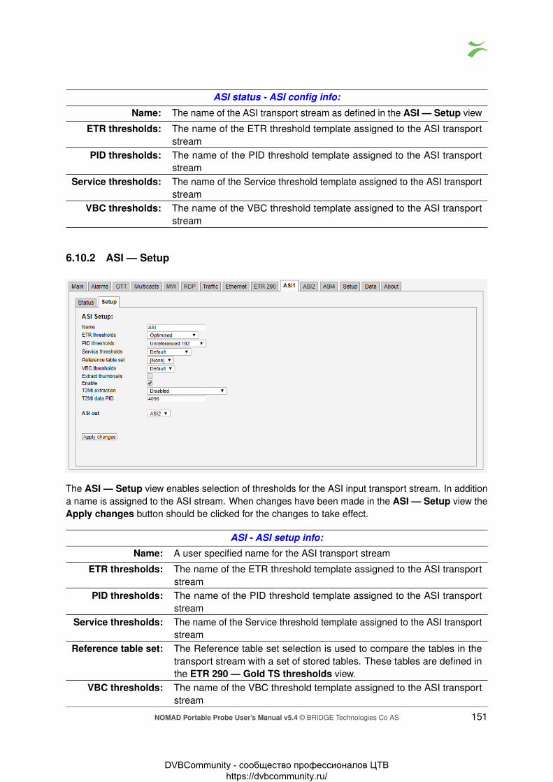
ASI status - ASI config info:
Name: The name of the ASI transport stream as defined in the ASI — Setup view
ETR thresholds: The name of the ETR threshold template assigned to the ASI transportstream
PID thresholds: The name of the PID threshold template assigned to the ASI transportstream
Service thresholds: The name of the Service threshold template assigned to the ASI transportstream
VBC thresholds: The name of the VBC threshold template assigned to the ASI transportstream
6.10.2 ASI — Setup
The ASI — Setup view enables selection of thresholds for the ASI input transport stream. In additiona name is assigned to the ASI stream. When changes have been made in the ASI — Setup view theApply changes button should be clicked for the changes to take effect.
ASI - ASI setup info:
Name: A user specified name for the ASI transport stream
ETR thresholds: The name of the ETR threshold template assigned to the ASI transportstream
PID thresholds: The name of the PID threshold template assigned to the ASI transportstream
Service thresholds: The name of the Service threshold template assigned to the ASI transportstream
Reference table set: The Reference table set selection is used to compare the tables in thetransport stream with a set of stored tables. These tables are defined inthe ETR 290 — Gold TS thresholds view.
VBC thresholds: The name of the VBC threshold template assigned to the ASI transportstream
NOMAD Portable Probe User’s Manual v5.4 © BRIDGE Technologies Co AS 151
DVBCommunity - cообщество профессионалов ЦТВ https://dvbcommunity.ru/

Extract thumbnails: When enabled, the probe will generate thumbnails for this tuning when-ever tuned to it. If not, they can be generated manually by opening thethumbnail pop-up from the Main — Thumb overview and ETR 290 —Services views. In order to enable this option, extract thumbnails alsohas to be enabled in the Setup — Params view
Enable: Check the box to enable ASI monitoring and alarming.
T2MI extraction: Enables extraction of T2MI.T2MI data PID: PID of the container stream.
ASI out: Select the input to be carried through ASI out.
6.11 COFDM/QAM
The COFDM/QAM tab will show the status for the RF-B input on the NOMAD. This input can receivesignals in DVB-T, DVB-T2 and DVB-C format.
Thumbnails for the RF demodulated services are accessed from the ETR 290 — Services and Main— Thumb overview views.
6.11.1 COFDM/QAM — Status
The COFDM/QAM — Status view gives an overview of the key input interface parameters. TheCOFDM/QAM status view displays the following information:
DVB-T/T2/C status - Stream info:Packet length: Indicates if the transport stream packets are 188 or 204 bytes
Original network ID: The original network ID as specified in the NIT table
Network ID: The network ID as specified in the NIT table
Transport stream ID: The transport stream ID as specified in the PAT table
152 NOMAD Portable Probe User’s Manual v5.4 © BRIDGE Technologies Co AS
DVBCommunity - cообщество профессионалов ЦТВ https://dvbcommunity.ru/

Total bitrate: Total transport stream bitrate including null packets (PID 8191)
Min total bitrate: The minimum total bitrate including null packets
Max total bitrate: The maximum total bitrate including null packets
Effective Bitrate: Transport stream bitrate excluding null packets (PID 8191)
Min effective bitrate: The minimum effective bitrate excluding null packets
Max effective bitrate: The maximum effective bitrate excluding null packets
DVB-T/T2/C status - DVB-T/T2/C demod info:Sync: A ‘bulb’ indicating frequency lock when green, red indicates
no lockLevel: This is a measure of the stream signal power. It is expressed
according to the level mode selection made in the Setup —ETR view:dBm: in decibels relative to a reference value of 1mW.dBμV: in decibels relative to a reference value of 1μVdBmV: in decibels relative to a reference value of 1mV
Signal to noise ratio: The signal to noise ratio in dB
Modulation error ratio: The modulation error ratio in dBFrequency offset: The measured center frequency offset in kHz
Spectrum inversion: The spectrum inversion parameter may have the value ‘Nor-mal’ or ‘Inverted’.
Pre Viterbi BER: Pre LDPC BER: The bit error rate before Viterbi or LDPC error correctionPre RS BER: Pre BCH BER: The bit error rate before RS or BCH error correction
Post BCH FER: The frame error rate after BCH error correction1 PPS input lock: A ‘bulb’ indicating reference signal lock when green, red
indicates no lockSFN drift: The SFN drift measured for the demodulated signal, with the
configured SFN drift zero offset subtracted
SFN network delay: SFN network delay is the accumulated network transmissiondelay as seen by the probe at any point after the SFN adapter
LDPC: Low-density parity-check iteration counter (only for DVB-T2)
DVB-T/T2/C status - DVB-T/T2/C tuning info:
Name: The name assigned to the current frequency channel
Frequency: The channel center frequency in MHz
Transmission system: The transmission system can be DVB-T or DVB-T2
Channel spacing: The channel spacing in MHz
ETR thresholds: The name of the ETR threshold template assigned to the currentfrequency
PID thresholds: The name of the PID threshold template assigned to the currentfrequency
NOMAD Portable Probe User’s Manual v5.4 © BRIDGE Technologies Co AS 153
DVBCommunity - cообщество профессионалов ЦТВ https://dvbcommunity.ru/

Service thresholds: The name of the Service threshold template assigned to the currentfrequency
DVB-T/T2/C thresholds: The name of the DVB-T/T2/C threshold template assigned to thecurrent frequency
VBC thresholds: The name of the VBC threshold template assigned to the currentfrequency
Please note: If the signal power is stronger than -10 dBm there will be a warning shown by GUI. Thisis to warn a user to apply some attenuation on the input to protect the analog front end on the VB252.
Click the Show additional parameters button to view L1 and PLP details. The L1 and PLP informa-tion is not relevant for DVB-C signals (QAM).
In case of DVB-T signal the additional parameters are shown in the following manner:
DVB-T L1 InformationMode: The OFDM mode (DFT size). Possible OFDM modes are 2K and 8K
GI: The guard interval. The guard interval may be 1/4, 1/8, 1/16 or 1/32
Constellation: Modulation constellation. Constellation may be QPSK, 16-QAM or 64-QAM
Hierarchy: DVB-T hierarchy can have the values ‘None’, 1, 2 or 4.
HP code rate: The FEC mode used for the high priority transport stream
LP code rate: The FEC mode used for the low priority transport stream
Cell ID: The cell ID is a number identifying the transmitter.
Detected mode: The detected OFDM modeDetected guard: The detected guard interval
In case of DVB-T2 signal the additional parameters are shown in the following manner:
154 NOMAD Portable Probe User’s Manual v5.4 © BRIDGE Technologies Co AS
DVBCommunity - cообщество профессионалов ЦТВ https://dvbcommunity.ru/

DVB-T2 L1 Pre InformationT2 Version: DVB-T2 Version:
1.1.11.2.11.3.1
Post scrambling: Informs if L1-Post scrambling is enabled, supported from DVB-T2v1.3.1 ‘True’ or ‘false’.
DVB-T2 profile: Determines current profile of DVB-T2 Signal:BaseLite (supported form DVB-T2 v1.3.1)
Base compatible with Lite: Indicates if the DVB-T2 Base Profile is compatible with DVB-T2Lite profile. If Base is incompatible with Lite one has to specifycorrectly which profile should be used for tuning: Base or Lite. Ifthere is compatibility between both DVB-T2 profiles the tuning willbe successful with any of them. ‘True’ or ‘False’
Type: The stream type contained within the current T2 super-frame.TS (Transport stream only)GS (Generic streams only)Mixed TS and GSThe OFDM mode (DFT size). Possible OFDM modes are 1K, 2K,4K, 8K, 16K and 32K
BW extended: Bandwidth extension indicator (only for 8K/ 16K/ 32K) True or False
S1: S1 Signaling. P1 S10 – SISO (Single input, single output)1 – MISO (Multiple input, single output)2 – Non DVB-T2
NOMAD Portable Probe User’s Manual v5.4 © BRIDGE Technologies Co AS 155
DVBCommunity - cообщество профессионалов ЦТВ https://dvbcommunity.ru/

S2: S2 Signaling. P1 S20 – DVB-T2 2K mode with any guard.2 – DVB-T2 8K mode with DVB-T guard.4 – DVB-T2 4K mode with any guard.6 – DVB-T2 1K mode with any guard.8 – DVB-T2 16K mode with any guard.10 – DVB-T2 32K mode with DVB-T guard.12 – DVB-T2 8K mode with DVB-T2 guard.14 – DVB-T2 32K mode with DVB-T2 guard.
Mixed: Mixed signaling indicator.0 – Not mixed.1 – Mixed (from S2 field).
FFT Mode: Specifies window size of Fast-Fourier-Transform (from S2 signal-ing). ‘1K’, ‘2K’, ‘4K’, ‘8K’, ‘16K’, ‘32K’
L1 Repeat: L1 repeat enable flag. ‘True’ or ‘False’.
GI: The guard interval used for the current super-frame. ‘1/4’, ‘1/8’,”1/16”, ‘1/32’, ‘1/218’, ‘19/128’, ‘19/256’
PAPR: Peak to average power ratio indicator. ‘None’, ‘ACE’, ‘TR’, ‘TR-ACE’
L1 post constellation: The L1-post modulation in the current frame. ‘BPSK’, ‘QPSK’,‘16-QAM’, ‘64-QAM’.
L1 post Code Rate: The L1-post code rate in this frame. ‘1/2’
L1 post FEC: The L1-post FEC (Forward Error Correction) type. ‘16K LDPC(Low-density parity-check).’
L1 post size: Size of the L1-post in OFDM cells.
L1 post info size: L1-post info size = L1-post configurable + dynamic + extension.
PP: The pilot pattern for the OFDM symbols in this frame. ‘1’, ‘2’, ‘3’,‘4’, ‘5’, ‘6’, ‘7’, ‘8’.
TX ID availability: The TX id.
Cell ID: The T2 cell Id.Network ID: The T2 network Id.System ID: The T2 system Id.
Number frames: Number of T2-frames per T2 super-frame.
Number symbols: Number of OFDM symbols per T2-Frame.
Regen: Regeneration count indicator.
Post ext: L1-post extensions enabled.
Number RF Freqs: The number of RF frequencies in use.
RF Index: The current RF index.PLP count: Number of PLPS (Physical Layer Pipes)
DVB-T2 L1 PLP Information:Id: The PLP (Physical Layer Pipe) Id.
156 NOMAD Portable Probe User’s Manual v5.4 © BRIDGE Technologies Co AS
DVBCommunity - cообщество профессионалов ЦТВ https://dvbcommunity.ru/

Type: The type of the PLP. ‘Common type’, ‘Data 1’, ‘Data 2’.
Group id: The group of PLPs that this PLP belongs to.
Constellation: The constellation of the current PLP. ‘QPSK’, ‘16-QAM’, ‘64-QAM’,‘256-QAM’.
Code rate: The code rate of this PLP. ‘1/2’, ‘2/3’, ‘3/5’, ‘3/4’, ‘4/5’ - DVB-T2 Baseonly, ‘5/6’ - DVB-T2 Base only, ‘1/3’ - DVB-T2 Lite only, ‘2/5’ - DVB-T2Lite only.
Rotated: Indicates if constellation is rotated. ‘True’ or ‘False’.FEC: The FEC (Forward Error Correction) type used on this PLP. ‘LDPC
(Low-density parity-check) 16K (Short FECFrame)’, ‘LDPC (Low-density parity-check) 64K (Long FECFrame)’. - DVB-T2 Base Only.
Num blocks: Maximum number of PLP blocks.Frame interval: The T2 frame interval within the super frame of this PLP.
Time interleaver length: Time interleaver length.
Time interleaver type: Indicates type of Time Interleaver.
In band A signaling: In-band A flag. Indicates whether PLP carries in-band signaling. ‘True’or ‘False’.
In band B signaling: In-band B flag, Indicates whether PLP carries in-band signaling. ‘True’or ‘False’.
In band B TS rate: In-band B signaling TS rate.
Payload: The payload carried by the PLP. ‘GFPS (Generic Fixed-length Packe-tized Stream)’, ‘GCS (Generic Continuous Stream)’, ‘GSE (GenericEncapsulated Stream)’, ‘TS (Transport Stream)’
Null packet detection: Null packet detection indicator. ‘True’ or ‘False’.
ISSY: Input Stream Synchronization Indicator. ‘True’ or ‘False’.
Mode: PLP (Physical Layer Pipe) Mode. ‘HEM (High Efficiency Mode)’,‘Normal’
DVB-T2 L1 Post InformationSub Slices per frame: The number of sub-slices per T2 Frame.
PLP count: The number of PLPs (Physical Layer Pipes) in the current super frame.
Aux count: Number of auxiliary streams.
Aux config: Auxiliary stream config.
RF index: The RF index.Frequency (Hz): The frequency in Hz for the given RF index.
FEF type: Indicates the type of FEF (Future Extension Frames) part.
FEF length: The length of the FEF (Future Extension Frames) as part of the elemen-tary period.
FEF interval: The number of T2-Frames between two FEF (Future Extension Frames)parts.
NOMAD Portable Probe User’s Manual v5.4 © BRIDGE Technologies Co AS 157
DVBCommunity - cообщество профессионалов ЦТВ https://dvbcommunity.ru/

6.11.2 COFDM/QAM — Tuning setup
In this view the operator can define frequencies that will be used by the RF demodulator for tuning. Aname is associated with each tuning configuration, and this name will be used by the probe whenreferring to the stream. The frequencies and some associated key parameters are shown in thetuning list. Each entry in the list may be edited by clicking the Edit field.
To add a new frequency to the list click the Add new tuning button. A pop-up window will appearallowing the user to enter tuning parameters.
When one set of tuning parameters has been defined it is possible to click the button Import fromNIT in order to have the other frequencies automatically added to the list, as defined in the NetworkInformation Table(s) analyzed by the probe. Default values will be assigned to parameters that arenot part of the NIT.
The following parameters are defined for each tuning entry:
DVB-T/T2/C — Tuning setup — Edit:
158 NOMAD Portable Probe User’s Manual v5.4 © BRIDGE Technologies Co AS
DVBCommunity - cообщество профессионалов ЦТВ https://dvbcommunity.ru/

Name: A name should be assigned to each tuning configuration.
Frequency: The channel center frequency in MHz. Note that the center frequencyof DVB-T/T2 transmissions is sometimes changed by an offset of±167 kHz in order to avoid interference with neighboring analoguechannels. In this case this frequency setting should be adjustedaccordingly.
Channel spacing: The channel spacing in MHz
Transmission system: Selection of DVB-C, DVB-T or DVB-T2 transmission system.
DVB-T2 profile: Determines current profile of DVB-T2 signal:BaseLite (supported form DVB-T2 v1.3.1)
PLP selection: The Physical Layer Pipe to be demodulated and analyzed. A specificPLP-ID may be selected or PLP selection can be set to ‘Auto’. Onlyapplicable for DVB-T2.
ETR thresholds: Selection of the ETR threshold template that should be assigned tothe current frequency
PID thresholds: Selection of the PID threshold template that should be assigned to thecurrent frequency
Service thresholds: Selection of the Service threshold template that should be assignedto the current frequency
Reference table set: The Reference table set selection is used to compare the tables in thetransport stream with a set of stored tables. These tables are definedin the ETR 290 — Gold TS thresholds view.
DVB-T/T2/C thresholds: Selection of the DVB-T/T2/C threshold template that should be as-signed to the current frequency
VBC thresholds: Selection of the VBC threshold template that should be assigned tothe current frequency
Extract thumbnails: When enabled, the probe will generate thumbnails for this tuningwhenever tuned to it. If not, they can be generated manually byopening the thumbnail pop-up from the Main — Thumb overviewand ETR 290 — Services views.
Enable tuning: If this box is checked, the transport stream associated with the currentfrequency will be monitored
It is also possible to add new frequencies manually by copying existing tuning list entries using theDuplicate highlighted button.
Multi-edit functionality makes it possible to edit several threshold templates simultaneously. Highlightthe tuning list entries that should be edited and click the Edit selected button.
Note that all tunings will automatically be ETR 290 analyzed, and hence be part of the round-robinloop unless the ‘Enable tuning’ box is unchecked.
Clicking the Import from NIT button will open the NIT Import pop-up view.
NOMAD Portable Probe User’s Manual v5.4 © BRIDGE Technologies Co AS 159
DVBCommunity - cообщество профессионалов ЦТВ https://dvbcommunity.ru/

NIT Import
Import DVB-T tuning entries: Mark the check-box if DVB-T if DVB-T tuning entries should beimported
Import DVB-T2 tuning entries: Mark the check-box if DVB-T if DVB-T2 tuning entries shouldbe imported
Select NIT: The ‘Select NIT’ drop-down menu shows NIT tables availablein the transport stream currently being analyzed. Information inthe selected NIT will be used to generate a tuning list when theImport tunings button is clicked.
Naming policy: The probe will automatically name tunings according to thenaming policy selected by the user: ‘Frequency’, ‘TS ID’ or ‘TSID and frequency’.
Rename existing: If the ‘Rename existing’ checkbox is marked, imported tuningsthat are already present in the tuning list will be renamed inaccordance with the naming policy selected by the user.
6.11.3 COFDM/QAM — COFDM/QAM threshold
The probe will raise an alarm if one of the threshold settings associated with a tuning is violated. Notethat this alarm may be disabled in the ETR 290 — ETR thr. — Edit view (Input interface checks).
In the threshold template list the ‘Refs’ column shows how many streams are associated with eachtemplate.
To add a new threshold template to the list, click the Add new threshold or Duplicate selectedbutton. A pop-up window will appear allowing the user to enter parameters.
160 NOMAD Portable Probe User’s Manual v5.4 © BRIDGE Technologies Co AS
DVBCommunity - cообщество профессионалов ЦТВ https://dvbcommunity.ru/

One or more threshold templates may be deleted or edited by highlighting them and clicking theDelete selected or Edit selected button.
The predefined threshold templates Default and Analog carrier cannot be edited or deleted.
The DVB-T/T2/C threshold parameters are:
DVB-T/T2/C threshold — Edit:Name: A text field describing the threshold template
Maximum pre Viterbi/LDPC BER: Threshold level for bit error ratio before Viterbi or LDPC errorcorrection
Maximum pre RS/BCH BER: Threshold level for bit error ratio before Reed-Solomon orBCH error correction
Maximum post BCH FER: Threshold level for bit error ratio after BCH error correction
Minimum MER: Threshold level for calculated modulation error ratioMinimum signal to noise ratio: Threshold level for signal to noise ratio (dB)
Minimum signal strength: Threshold level for minimum signal strength. This is a mea-sure of the stream signal power. It is expressed accordingto the level mode selection made in the Setup — ETR view:dBm: in decibels relative to a reference value of 1mWdBμV: in decibels relative to a reference value of 1μVdBmV: in decibels relative to a reference value of 1mV
Maximum signal strength: Threshold level for maximum signal strength. This is a mea-sure of the stream signal power. It is expressed accordingto the level mode selection made in the Setup — ETR view:dBm: in decibels relative to a reference value of 1mWdBμV: in decibels relative to a reference value of 1μVdBmV: in decibels relative to a reference value of 1mV
NOMAD Portable Probe User’s Manual v5.4 © BRIDGE Technologies Co AS 161
DVBCommunity - cообщество профессионалов ЦТВ https://dvbcommunity.ru/

Signal strength offset: It is possible to use the signal strength offset adjustmentto calibrate the COFDM demodulator. This is achieved bytuning to a COFDM signal of known level and setting thisadjustment accordingly.
Maximum frequency offset: Threshold level for maximum center frequency offset
Frequency offset zero adjust: Allows to define calibration adjustment for frequency offset
Maximum LDPC iterations: Threshold level for Low-density parity-check iteration counter(only for DVB-T2)
The impulse response checking threshold values are only relevant when the probe is licensed withthe Advanced RF Option and for DVB-T/T2 signals. Threshold values for each impulse will becomevisible in the COFDM/QAM — Impulse response view as a highlighted box in the impulse responsegraph. If an impulse peak does not fall within its box an alarm will be raised. Threshold values for amaximum of ten impulses may be defined.
Impulse response checking:
Enable impulse response measurements: Enable or disable impulse response measure-ments. Impulse response measurements are timeconsuming and should only be enabled whenneeded.
Impulse detection limit: The impulse detection limit in dB. Signal peakswith lower level than the detection limit will be re-garded as noise and not considered an impulse.
Force HPI first: Force highest impulse response first. This forcesthe highest impulse response to t=0 in the impulseresponse graph.
Enable: It is possible to enable or disable time location andlevel check of an impulse. Mark the ‘Enable’ check-box for the probe to raise alarm if an impulse peakis not found within the graph box defined by thespecified time and power limits.
Name: A text string specified by the user to name animpulse. Typically this will be the name of a trans-mitter.
Time min: The minimum time an impulse should occur afterthe main impulse
Time max: The maximum time an impulse should occur afterthe main impulse
Power min: The minimum power of an impulse compared tothe main impulse (in dB)
Power max: The maximum power of an impulse compared tothe main impulse (in dB)
162 NOMAD Portable Probe User’s Manual v5.4 © BRIDGE Technologies Co AS
DVBCommunity - cообщество профессионалов ЦТВ https://dvbcommunity.ru/
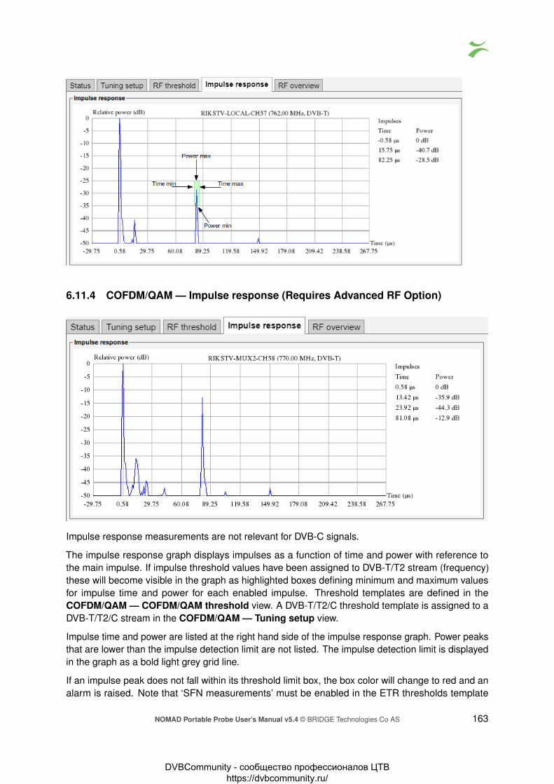
6.11.4 COFDM/QAM — Impulse response (Requires Advanced RF Option)
Impulse response measurements are not relevant for DVB-C signals.
The impulse response graph displays impulses as a function of time and power with reference tothe main impulse. If impulse threshold values have been assigned to DVB-T/T2 stream (frequency)these will become visible in the graph as highlighted boxes defining minimum and maximum valuesfor impulse time and power for each enabled impulse. Threshold templates are defined in theCOFDM/QAM — COFDM/QAM threshold view. A DVB-T/T2/C threshold template is assigned to aDVB-T/T2/C stream in the COFDM/QAM — Tuning setup view.
Impulse time and power are listed at the right hand side of the impulse response graph. Power peaksthat are lower than the impulse detection limit are not listed. The impulse detection limit is displayedin the graph as a bold light grey grid line.
If an impulse peak does not fall within its threshold limit box, the box color will change to red and analarm is raised. Note that ‘SFN measurements’ must be enabled in the ETR thresholds template
NOMAD Portable Probe User’s Manual v5.4 © BRIDGE Technologies Co AS 163
DVBCommunity - cообщество профессионалов ЦТВ https://dvbcommunity.ru/

associated with a DVB-T/T2 stream for impulse check alarming to be active. ETR threshold templatesare defined in the ETR 290 — ETR thr. view. An ETR threshold template is assigned to a DVB-T/T2/Cstream in the COFDM/QAM — Tuning setup view.
6.11.5 COFDM/QAM — RF overview
The RF parameters and measurements list gives a status overview of all monitored DVB-T/T2/Cfrequencies from the selected RF input. The parameters and measurements in this list refer to thelast completed monitoring period or, for a stream currently monitored, the current monitoring period.
List of RF parameters and measurements:
Frequency: The stream frequency that the associated parameters apply to
Trans. System: The transmission system: DVB-T or DVB-T2
Channel spacing: The channel bandwidth
TS sync: Transport stream sync: yes or no
Min level: The minimum RF signal level
Max level: The maximum RF signal level
Min SNR: The minimum signal to noise ratio
Min MER: The minimum calculated modulation error ratioMax pre FB: The maximum bit error rate before Viterbi or LDPC error correction
Max post FB: The maximum bit error rate before BCH error correction
Max post BF: The maximum bit error rate after BCH error correction
1 PPS lock: An indication of reference signal lock. The value may be ‘Locked’ or ‘Nolock’.
Max SFN drift: The maximum SFN drift (in µs) detected during the monitoring period
Max LDPC: The maximum Low-density parity-check (LDPC) iteration counter value (onlyfor DVB-T2)
6.12 SAT
The SAT tab will show the status for the RF-A input on the NOMAD. This input can receive signals inDVB-S and DVB-S2 format.
Thumbnails of SAT services are accessed from the ETR 290 — Services and Main — Thumboverview views.
164 NOMAD Portable Probe User’s Manual v5.4 © BRIDGE Technologies Co AS
DVBCommunity - cообщество профессионалов ЦТВ https://dvbcommunity.ru/

6.12.1 SAT — Status
The SAT — Status view gives an overview of the key input interface parameters.
The SAT status view displays the following information:
SAT status - Stream info:Stream type: Indicates transmission system: DVB-S or DVB-S2
Packet length: Indicates if the transport stream packets are 188 or 204 bytes
Original network ID: The original network ID as specified in the NIT table
Network ID: The network ID as specified in the NIT table
Transport stream ID: The transport stream ID as specified in the PAT table
Total bitrate: Current total transport stream bitrate (including null packets – (PID 8191))
Min total bitrate: Minimum total transport stream bitrate (including null packets)
Max total bitrate: Maximum total transport stream bitrate (including null packets)
Effective bitrate: Current transport stream bitrate (excluding null packets)
Min effective bitrate: Minimum transport stream bitrate (excluding null packets)
Max effective bitrate: Maximum transport stream bitrate (excluding null packets)
SAT status - SAT tuner / demod info:Front-end lock: A “bulb” indicating front end lock when green, red indicates no lock
NOMAD Portable Probe User’s Manual v5.4 © BRIDGE Technologies Co AS 165
DVBCommunity - cообщество профессионалов ЦТВ https://dvbcommunity.ru/

Level: This is a measure of the stream signal power. It is expressed accord-ing to the level mode selection made in the Setup — ETR view:dBm: in decibels relative to a reference value of 1mWdBμV: in decibels relative to a reference value of 1μVdBmV: in decibels relative to a reference value of 1mV
BER (pre Viterbi): The bit error rate before forward error correction (Viterbi) applies onlyto DVB-S
BER (post Viterbi): The bit error rate after forward error correction (Viterbi) applies onlyto DVB-S
BER (post LDPC-BCH): The bit error rate after forward error correction (LDPC-BCH) appliesonly to DVB-S2
Packet error count: The number of erroneous packets after FEC. Packet errors are dueto either packet loss or packet bit errors
Signal to noise ratio: Signal to noise ratio in dB
Modulation error rate: Modulation error rate in dBError Vector Magnitude: Error Vector Magnitude in %
Error Vector Magnitude: Error Vector Magnitude in dB
Eb/N0: Energy per transmitted bit to noise power spectral density ratio in dB
Ebinf/N0: Energy per information bit to noise power spectral density ratio in dB
Es/N0: Energy per symbol to noise power spectral density ratio in dB
Transmission system: The modulation standard – may be DVB-S, DVB-S2.
Modulation: The SAT modulation scheme – may be QPSK, 8PSK, 16APSK or32APSK
Tuner bandwidth: The tuner bandwidth in MHzTuner frequency: The RF tuner frequency in GHz
Center frequency offset: The measured center frequency offset in kHz
Roll-off factor: The filter roll-off factor – one of the following: 0.2, 0.25, 0.35
Actual symbol rate: The actual SAT symbol rate in Msym/s
Symbol rate offset: The offset between defined and actual symbol rate in sym/s
FEC rate: The forward error correction rate – may be 1/2, 2/3, 3/4, 4/5 (forTurbocode only),5/6, 6/7 (for DSS only), 7/8 or 8/9 (for Turbocodeonly)
Spectrum inversion: Indicates whether the spectrum is inverted or normal
Num input streams: Indicates whether the Single Input Stream (SIS) or Multiple InputStream (MIS) is used
Coding and modulation: Indicates type of coding – one of the following: Constant Coding andModulation (CCM) or Adaptive Coding and Modulation (ACM) – VCMis signaled as ACM.
ISSI: Shows if Input Stream Synchronization Indicator is Enabled or Dis-abled
Null packet deletion: Indicates if Null packet deletion (NPD) is Enabled or Disabled
166 NOMAD Portable Probe User’s Manual v5.4 © BRIDGE Technologies Co AS
DVBCommunity - cообщество профессионалов ЦТВ https://dvbcommunity.ru/

Pilot detection: Indicates if pilot detection is Enabled or Disabled – applies only toDVB-S2
Frame length: Indicates frame length – one of the following: “NORMAL FRAME– 64800 bits” or “SHORT FRAME – 16200 bits” – applies only toDVB-S2
SAT status - SAT requested tuning info:
Setup name: A name should be assigned to each frequency channel
Transponder frequency: The transponder frequency in GHz
LNB LO: The LNB LO frequency in GHz
LNB voltage: The LNB voltage - may be 0V, 13V or 18V
22kHz tone: Enable or disable 22kHz toneDiSEqC: The satellite front-end module supports DiSEqC 1.2 signaling. The
operator can enable a particular DiSEqC message to be transmit-ted towards the antenna for each frequency defined in the tuningsetup typically used to control L-band switches. Specifically, themessage sent has the format ( 0xE0 0x10 0x38 N ), where N is abyte configurable by the user to be between 0x00 and 0x0f. This isthe command 0x38 “Write to Port group 1 (Committed switches)”.
Selected symbol rate: The selected SAT symbol rate in Msym/s
Selected input stream ID: The selected input stream identifier in Multi input stream (MIS) or“No filter” in Single input stream (SIS) – applies only to DVB-S2
PL scrambling mode: The PL scrambling mode selected: None, Gold, Root – applies onlyto DVB-S2
PL scrambling code: The PL scrambling code: 0–262141 – applies only to DVB-S2
ETR thresholds: Selection of the ETR threshold template that should be assigned tothe current frequency
PID thresholds: Selection of the PID threshold template that should be assigned tothe current frequency
Service thresholds: Selection of the Service threshold template that should be assignedto the current frequency
SAT thresholds: Selection of the SAT threshold template that should be assigned tothe current frequency
VBC thresholds: The name of the VBC threshold template assigned to the currentfrequency
The constellation diagram displays the received symbols with respect to phase and amplitude.
NOMAD Portable Probe User’s Manual v5.4 © BRIDGE Technologies Co AS 167
DVBCommunity - cообщество профессионалов ЦТВ https://dvbcommunity.ru/

6.12.2 SAT — Tuning setup
In this view the operator can define frequencies that will be used by the SAT demodulator for tuning.A name is associated with each frequency, and this name will be used by the probe when referring tothe stream. The frequencies and some associated key parameters are shown in the SAT tuning list.Each entry in the list may be edited by clicking the Edit field.
To add a new frequency to the list click the Add new tuning button. A pop-up window will appearallowing the user to enter tuning parameters.
Multi-edit functionality makes it possible to edit selected streams simultaneously. Highlight the tuninglist entries that should be edited and click the Edit selected button.
When one set of tuning parameters has been defined it is possible to click the button Import fromNIT in order to have the other frequencies automatically added to the list, as defined in the NetworkInformation Table analyzed by the probe. Default values will be assigned to parameters that are not apart of the NIT.
168 NOMAD Portable Probe User’s Manual v5.4 © BRIDGE Technologies Co AS
DVBCommunity - cообщество профессионалов ЦТВ https://dvbcommunity.ru/

Clicking the Import from NIT button will open the NIT Import pop-up view.
NIT Import
Select NIT: The ‘Select NIT’ drop-down menu shows NIT tables available in the transportstream currently being analyzed. Information in the selected NIT will be usedto generate a tuning list when the Import tunings button is clicked.
Naming policy: The probe will automatically name tunings according to the naming policyselected by the user: ‘Frequency’, ‘TS ID’ or ‘TS ID and frequency’.
Rename existing: If the ‘Rename existing’ checkbox is marked, imported tunings that arealready present in the tuning list will be renamed in accordance with thenaming policy selected by the user.
The following parameters are defined for each SAT frequency:
SAT - Tuning setup:
Name: A name should be assigned to each frequency channel
Transponder frequency: The transponder frequency in GHz
LNB Local osc.: The LNB local oscillator frequency in GHz
LNB voltage: The LNB voltage - may be 0V, 13V or 18V
22kHz tone: Enable or disable 22kHz toneDiSEqC: The satellite front-end module supports DiSEqC 1.2 signaling. The
operator can enable a particular DiSEqC message to be transmittedtowards the antenna for each frequency defined in the tuning setuptypically used to control L-band switches. Specifically, the messagesent has the format ( 0xE0 0x10 0x38 N ), where N is a byte config-urable by the user to be between 0x00 and 0x0f. This is the command0x38 “Write to Port group 1 (Committed switches)”.
Symbol rate: The SAT symbol rate in Msym/s
Input stream selection: Chooses the input stream identifier (ISI) for Multi input stream (MIS),AUTO should be selected for Single input stream (SIS) – applies onlyto DVB-S2
PL scrambling mode: The PL scrambling mode selected: None, Gold, Root – applies onlyto DVB-S2
PL scrambling code: The PL scrambling code: 0–262141 – applies only to DVB-S2
ETR thresholds: Selection of the ETR threshold template that should be assigned tothe current frequency
PID thresholds: Selection of the PID threshold template that should be assigned tothe current frequency
NOMAD Portable Probe User’s Manual v5.4 © BRIDGE Technologies Co AS 169
DVBCommunity - cообщество профессионалов ЦТВ https://dvbcommunity.ru/

Service thresholds: Selection of the Service threshold template that should be assignedto the current frequency
SAT thresholds: Selection of the SAT threshold template that should be assigned tothe current frequency
VBC thresholds: Selection of the VBC threshold template that should be assigned tothe current frequency
Enable tuning: Enable tuning for frequencies that should be monitored. If tuning fora stream is enabled it will automatically be part of the round-robinanalysis loop.
It is also possible to add new frequencies manually by copying existing tuning list entries using theDuplicate highlighted button.
Recommended Symbol rate values
The following table gives the recommended Symbol rate setting, depending on actual symbol rate ofthe input RF signal:
Actual Symbol rate Configured Symbol rate
1 MS/s 1–4 MS/s6 MS/s 1–9 MS/s22 MS/s 1–38 MS/s35 MS/s 1–45 MS/s45 MS/s 1–45 MS/s
6.12.3 SAT — Frequency scan
170 NOMAD Portable Probe User’s Manual v5.4 © BRIDGE Technologies Co AS
DVBCommunity - cообщество профессионалов ЦТВ https://dvbcommunity.ru/

As opposed to a satellite scan, which scans according to pre-set transponder values it’s purposeis to find transponders on a particular satellite without any scanning rules. It “blindly” scans everypossible horizontal and vertical satellite frequency and symbol rate. It means that the tuner will do anautomatic scan of the incoming satellite signal in small steps for active symbol rates to determine ifthere are any live transponder signals.
In order to start frequency scan fill in parameters and click Start scanning. It is important to notethat monitoring will be suspended for the given input during the scan process. So if you want tointerrupt the process click the Interrupt button. After the frequency scan is finished the input statewill be restored to the state prior to the scan automatically.
To add frequencies to the tuning list select one or more transponders found and click the Addselected to tuning list.
Frequency scan parameters are:
SAT - Frequency scan:
LNB frequency: The LNB local oscillator frequency in GHz
Start frequency: The beginning of the range to scan in GHz
Stop frequency: The end of the range to scan in GHz
Scan step: Minimal step to scan the range in MHz
LNB voltage: The LNB voltage - may be 0V, 13V or 18V
22kHz tone: Enable or disable 22kHz toneDiSEqC: The satellite front-end module supports DiSEqC 1.2 signaling. The
operator can enable a particular DiSEqC message to be transmittedtowards the antenna for each frequency defined in the tuning setuptypically used to control L-band switches. Specifically, the message senthas the format (0xE0 0x10 0x38 N), where N is a byte configurable bythe user to be between 0x00 and 0x0f. This is the command 0x38 “Writeto Port group 1 (Committed switches)”.
Min. Symbol rate: The SAT symbol rate in Msym/s
PL scrambling mode: The PL scrambling mode selected: None, Gold, Root – applies only toDVB-S2
PL scrambling code: The PL scrambling code: 0-262141 – applies only to DVB-S2
6.12.4 SAT — SAT threshold
NOMAD Portable Probe User’s Manual v5.4 © BRIDGE Technologies Co AS 171
DVBCommunity - cообщество профессионалов ЦТВ https://dvbcommunity.ru/

The probe will raise an alarm if one of the threshold settings associated with a SAT frequency isviolated. Note that this alarm may be disabled in the ETR 290 — ETR thr. — Edit view (Inputinterface checks).
To add a new threshold template to the list click the Add new threshold button. A pop-up windowwill appear allowing the user to enter parameters.
The predefined threshold templates Default and Analog carrier cannot be edited or deleted.
The SAT threshold parameters are:
SAT Threshold - Edit:Name: A text field describing the threshold template
Pre Viterbi BER: Threshold level for bit error ratio before forward error correction(Viterbi) – only for DVB-S
Post Viterbi/LDPC-BCH: Threshold level for bit error ratio after forward error correctionMinimum SNR: Threshold level for minimum signal to noise ratio (dB)
Minimum Eb/N0: Threshold level for energy per transmitted bit to noise powerspectral density ratio (dB)
Maximum EVM: Threshold level for maximum error vector magnitude (dB)
Minimum signal strength: Minimum threshold level for signal strength.This is a measure of the stream signal power. It is expressedaccording to the level mode selection made in the Setup —ETR view:dBm: in decibels relative to a reference value of 1mWdBμV: in decibels relative to a reference value of 1μVdBmV: in decibels relative to a reference value of 1mV
172 NOMAD Portable Probe User’s Manual v5.4 © BRIDGE Technologies Co AS
DVBCommunity - cообщество профессионалов ЦТВ https://dvbcommunity.ru/

Maximum signal strength: Maximum threshold level for signal strength.This is a measure of the stream signal power. It is expressedaccording to the level mode selection made in the Setup —ETR view:dBm: in decibels relative to a reference value of 1mWdBμV: in decibels relative to a reference value of 1μVdBmV: in decibels relative to a reference value of 1mV
Maximum frequency offset: Threshold level for maximum frequency offset (Hz)
Frequency offset zero adjust: Allows to define calibration adjustment for frequency offset (Hz)
Maximum symbol rate offset: Threshold level for maximum symbol rate offset (sym/s)
Symbol rate zero adjust: Allows to define calibration adjustment for symbol rate offset(sym/s)
6.12.5 SAT — RF overview
The RF parameters and measurements list gives a status overview of all monitored SAT frequenciesfrom the selected RF input. The parameters and measurements in this list refer to the last completedmonitoring period or, for a stream currently monitored, the current monitoring period.
NOMAD Portable Probe User’s Manual v5.4 © BRIDGE Technologies Co AS 173
DVBCommunity - cообщество профессионалов ЦТВ https://dvbcommunity.ru/

6.13 Setup
6.13.1 Setup — Params
The Setup — Params view contains the following settings:
VariousProbe name: Each probe can be assigned a user defined name. The name is shown in
the Main — Summary view, which is the probe default page, as well as inthe browser’s title line.
Probe contact: The probe contact is part of the probe’s MIB, and this parameter is relevantfor SNMP use only.
Probe location: The probe location is part of the probe’s MIB, and this parameter is relevantfor SNMP use only. The probe location is also shown in the Main —Summary view and in the browser’s title line.
Enable thumbnails: For high bitrates (above 700 Mbit/sec) the probe may feel more responsiveif thumbnail picture generation is switched off. This does not affect theaccuracy of the measurements.
Date format: The date format used in the user interface can be changed here. Datesexported through machine-readable interfaces are not affected by thissetting.
AlarmsFreeze log when full: When enabled the alarm list will freeze when full (an event
will show that it is full). When the list is full new alarms areignored until Clear alarms is pressed.This can sometimes be useful if a unit is placed unattended.
Treat Ethernet events as alarms: When enabled each event is treated as an alarm that isactive for 5 seconds. This may be useful when reporting toexternal systems that do not support events but only activeor cleared alarms. This setting affects the local alarm listand SNMP traps.
174 NOMAD Portable Probe User’s Manual v5.4 © BRIDGE Technologies Co AS
DVBCommunity - cообщество профессионалов ЦТВ https://dvbcommunity.ru/

Network settings
Promiscuous network mode: The probe will only be able to detect additional multicasts if theEthernet interface is set in promiscuous mode. With this optionset to “off” the probe will not be able to detect multicasts notalready joined by the probe. The probe load increases when thisoption is enabled since more packets are inspected.
Join multicasts: If switched off probe will not send IGMP messages which isuseful if connected to a trunk port and there is no need to joinmulticasts.
Source specific multicasts: Required for probe to support the IGMP v3 protocol.
Time synchronization
Use time server: Select between Off, NTP (Ethernet), TDT (QAM, COFDM, SAT, ASI) andTOT (QAM, COFDM, SAT, ASI).When NTP is selected the probe will synchronize with an upstream NTPserver as often as is needed to maintain accurate timekeeping on the probe.If Off is selected, or NTP is selected and no NTP server is configured, theprobe will try to synchronize with the VBC server.When TDT time synchronization is enabled the probe will use the UTC timefound in the TDT table and add the configured local time offset. For probeswhich only have an ASI interface this input will be used as the clock source.For probes with one or more demodulator interfaces the first frequency on thefirst RF interface will be used.When TOT time synchronization is enabled the probe will use the UTC timefound in the TOT table and add the local time offset specified by the parameterTOT time zone. For probes which only have an ASI interface this input willbe used as the clock source. For probes with one or more demodulatorinterfaces, the first frequency on the first RF interface will be used.
NTP time server: The IP address or host name of the time server.Time zone: By setting the time zone the probe time can be offset from the reference NTP
time.TOT time zone: The local time zone to be used when TOT is selected as clock reference
source. This is a three letter country code that should match a country codepresent in the received TOT. Note that this parameter is case sensitive. If theTOT time zone field is left blank the first time zone specified in the TOT willbe used, and this time zone will also be used if the probe is unable to findthe specified country code in the TOT. For countries with more than one timezone the region ID is specified by adding a colon and the region ID to thecountry code (e.g. ‘USA:2’ for country USA and region ID 2).
802.1Q VLAN tagging
NOMAD Portable Probe User’s Manual v5.4 © BRIDGE Technologies Co AS 175
DVBCommunity - cообщество профессионалов ЦТВ https://dvbcommunity.ru/

Ignore VLAN tags If enabled together with Enable on eth0 the probe will see all VLAN taggedtraffic and not only traffic with the Native VLAN ID tag. The Mon/Detect listwill be able to detect and list all VLAN tagged traffic. Note that the probewill only issue IGMP messages on the native VLAN ID, and traffic taggeddifferently must be present at the interface to be detected.
SNMPCommunity string: The probe SNMP community string can be changed.
Trap destination 1–3: SNMP traps will be sent to the specified destinations. Set to 0.0.0.0 todisable SNMP trap transmission.
6.13.2 Setup — Pages
The Setup — Pages view allows names to be associated with different pages. Individual multicastscan be assigned to different pages in the Multicasts — Streams view, to facilitate easier navigation inthe different Multicasts views.
6.13.3 Setup — Colors (requires EXTRACT-OPT)
176 NOMAD Portable Probe User’s Manual v5.4 © BRIDGE Technologies Co AS
DVBCommunity - cообщество профессионалов ЦТВ https://dvbcommunity.ru/

The Setup — Colors view allows the user to define colors that should be recognized if a color-freezecondition should occur. A mono-colored freeze frame condition may in some cases indicate whatequipment is failing, resulting in the color-freeze.
A freeze color is defined by clicking the Add new color button and assigning an RGB value to aname. A maximum of four colors may be defined. An existing color may be modified by clicking theassociated Edit link.
Edit colorName: The color name. This name will be part of a color alarm description and the
associated SNMP trap.
Description: A description of the color or an error indication.
Color: The RGB color on the format #XX(Red)XX(Green)XX(Blue) where XX representsa hexadecimal figure spanning 0-255 in decimal notation. If supported by thebrowser, clicking the color should pop up a color selection dialog.
6.13.4 Setup — Time
The time of the probe is used to timestamp events in the alarm list. The local time is always presentedjust below the alarm list.
The probe time should not be set manually if the probe is synchronizing against a time server (referto the Setup — Params view).
If supported by the browser, you should be able to set the time and date using a calendar and timecontrol by clicking the input box.
NOMAD Portable Probe User’s Manual v5.4 © BRIDGE Technologies Co AS 177
DVBCommunity - cообщество профессионалов ЦТВ https://dvbcommunity.ru/

6.13.5 Setup — Ethernet
The WiFi interface on the NOMAD is configured in Setup — WiFi.
The Setup — Ethernet menu defines the Ethernet setup parameters for the management interface(eth1) and the data/video interface (RJ45/eth0 or SFP/eth2). If the license for the second datainterface is enabled, both data interfaces can be configured. The link statuses for the interfaces areupdated live to reflect the current settings. Rebooting the probe from this page is achieved by clickingthe Reboot button after changes have been confirmed by clicking the Apply button. Click the IPv6Settings button to access the IPv6 view.
The 10/100/1000 BASE-T management port corresponding to eth1 is located at the front of the probeand is labeled Management. For the data/video port, the user can choose between eth0, which isthe electrical 10/100/1000 BASE-T Ethernet port labeled 10/100/1000T, or eth2, which is the opticalgigabit SFP port labeled SFP. If the license for the second data interface is enabled, both data portscan be enabled simultaneously.
Connecting a data/video port is mandatory. The probe will only be able to join multicasts on thedata ports. For management, the probe supports both in-band management (i.e. using eth0 for bothdata/video and management) and separate management (i.e. using eth1 for management). In anycase make sure that the subnets configured for the network interfaces do not overlap – otherwisethe probe will not work properly. If the IP addresses for network interfaces are configured so that thesubnets overlap, the settings will be automatically reverted by the probe.
Dual stack functionality enables the probe to support both IPv4 and IPv6 for management.
A valid DNS configuration is required for parts of the probe functionality. Configure a valid DNS underthe Global settings heading, or use a publicly available DNS such as Google Public DNS (8.8.8.8 or8.8.4.4) or OpenDNS (208.67.222.22 or 208.67.220.220).
Data port input selection
Input: Select whether to use the electrical RJ45 (eth0) or the optical SFP (eth2) port as the dataport.
IP settings – data/video RJ45 (eth0)
178 NOMAD Portable Probe User’s Manual v5.4 © BRIDGE Technologies Co AS
DVBCommunity - cообщество профессионалов ЦТВ https://dvbcommunity.ru/

Enable DHCP: If enabled, IP address (eth0), netmask (eth0) and gateway are updatedby a remote DHCP server next time the probe boots.
IPv4 address: IPv4 IP address of management interface
IPv4 netmask: IPv4 netmask of management interface
Enable management: If enabled a web server will be started on eth0 next time the probe boots.
IP settings – data/video SFP (eth2)
Enable DHCP: If enabled, IP address (eth2), netmask (eth2) and gateway are updatedby a remote DHCP server next time the probe boots.
IPv4 address: IPv4 IP address of management interface
IPv4 netmask: IPv4 netmask of management interface
Auto-negotiation Check the box to actively attach to the network. Uncheck auto-negotiationif the SFP port is used to attach passively to a fiber tap.
Enable management: If enabled a web server will be started on eth2 next time the probe boots.
IP settings – management (eth1)
Enable DHCP: If enabled, IP address (eth1), netmask (eth1) and gateway are updatedby a remote DHCP server next time the probe boots.
IPv4 address: IPv4 address of the data/video interfaceIPv4 netmask: IPv4 netmask of data/video interface
Enable management: If enabled a web server will be started on eth2 next time the probe boots.
Global settings
Default interface: The default interface determines which interface is used for out-going probetraffic, unless specified otherwise in the Setup — Routing view.
DNS Server: If DHCP is not enabled, this field can be used to define the IP address ofthe DNS server. If DHCP is enabled, this field is disabled, and the gatewayprovided by the DHCP server is used.
NOMAD Portable Probe User’s Manual v5.4 © BRIDGE Technologies Co AS 179
DVBCommunity - cообщество профессионалов ЦТВ https://dvbcommunity.ru/

6.13.5.1 Setup — Ethernet — IPv6 Settings
IPv6 settings – data/video RJ45 (eth0)
Enable IPv6: If IPv6 is enabled, the probe will use IPv6 for management on eth0.
Enable IPv6autoconf: If IPv6 auto-configuration is enabled, the probe will receive IPv6 address,IPv6 prefix and gateway address from a network router when booting.
IPv6 address: If IPv6 auto-configuration is not enabled, this field is used to define theIPv6 address of the probe.
IPv6 prefix: If IPv6 auto-configuration is not enabled, this field is used to define theIPv6 prefix of the probe (corresponding to netmask for IPv4).
IPv6 Gateway: Required to allow clients with an address outside the probe subnets toaccess the probe (HTTP, FTP, SSH, TELNET, SNMP). It is also requiredfor the probe to access an NTP server or DNS server with IPv6 addressoutside the probe’s subnets. If IPv6 auto-configuration is enabled, thisfield is disabled.
Note that auto-configuration should only be enabled for one of the Ethernet ports to avoidpossible conflicts.
IPv6 settings – data/video SFP (eth2)
Enable IPv6: If IPv6 is enabled, the probe will use IPv6 for management on eth2.
Enable IPv6autoconf: If IPv6 auto-configuration is enabled, the probe will receive IPv6 address,IPv6 prefix and gateway address from a network router when booting.
IPv6 address: If IPv6 auto-configuration is not enabled, this field is used to define theIPv6 address of the probe.
IPv6 prefix: If IPv6 auto-configuration is not enabled, this field is used to define theIPv6 prefix of the probe (corresponding to netmask for IPv4).
180 NOMAD Portable Probe User’s Manual v5.4 © BRIDGE Technologies Co AS
DVBCommunity - cообщество профессионалов ЦТВ https://dvbcommunity.ru/

IPv6 Gateway: Required to allow clients with an address outside the probe subnets toaccess the probe (HTTP, FTP, SSH, TELNET, SNMP). It is also requiredfor the probe to access an NTP server or DNS server with IPv6 addressoutside the probe’s subnets. If IPv6 auto-configuration is enabled, thisfield is disabled.
IPv6 settings – management (eth1)
Enable IPv6: If IPv6 is enabled, the probe will use the management port for IPv6management
Enable IPv6autoconf: If IPv6 auto-configuration is enabled, the probe will receive IPv6 address,IPv6 prefix and gateway address from a network router when booting.
IPv6 address: If IPv6 auto-configuration is not enabled, this field is used to define theIPv6 address of the probe.
IPv6 prefix: If IPv6 auto-configuration is not enabled, this field is used to define theIPv6 prefix of the probe (corresponding to netmask for IPv4).
IPv6 Gateway: Required to allow clients with an address outside the probe subnets toaccess the probe (HTTP, FTP, SSH, TELNET, SNMP). It is also requiredfor the probe to access an NTP server or DNS server with IPv6 addressoutside the probe’s subnets. If IPv6 auto-configuration is enabled, thisfield is disabled.
6.13.5.2 Example 1 – Separate Management IPv4
This model is useful if the management traffic is to be separated from the data/video traffic byutilizing two completely disjointed networks. In this example the management subnet is defined as192.168.0.0/16 and the data/video subnet is 10.0.30.0/24.
Parameter Management(eth1)
Data/video(eth0)
Explanation
Enable DHCP Optional Optional Use DHCP to configure the eth1 and/oreth0 interface automatically
IP address 192.168.7.5 10.0.30.5 The IP addresses of each interfaceNetmask 255.255.0.0 255.255.255.0 The netmasks – 16 and 24 bitsEnablemanagement
Yes No Only run web server on the manage-ment interface
Gateway 192.168.0.1 – The default gateway is required for theprobe to connect to devices that are noton the same subnet
6.13.5.3 Example 2 – In-Line Management IPv4
This model is useful if there is no separate management network and both data/video and manage-ment traffic are to use the same network. In this configuration the probe’s management network may
NOMAD Portable Probe User’s Manual v5.4 © BRIDGE Technologies Co AS 181
DVBCommunity - cообщество профессионалов ЦТВ https://dvbcommunity.ru/

not even be connected. Even if the probe’s management port is not to be used it must be configuredcarefully so that it does not interfere with the data/video interface.
In this example there is only one network defined as 10.0.30.0/24.
Parameter Management(eth1)
Data/video(eth0)
Explanation
Enable DHCP Off Optional We cannot use DHCP for eth1 since thedevice is not used
IP address 0.0.0.0 10.0.30.5 The IP addresses of each interface –configure eth1 to a non-existing address
Netmask 255.255.255.255 255.255.255.0 The netmasks – the subnet for eth1 con-tains only one address
Enablemanagement
No Yes Only run web server on the data/videointerface
Gateway — 10.0.30.1 The default gateway is required for theprobe to connect to devices that are noton the same subnet
6.13.5.4 Example 3 – Mixed Mode IPv4
This model is similar to the separate management model with the difference that a web server is alsorun on the data/video management.
Since there is only one default gateway, in this case pointing to the management network, clientsaccessing the probe via the data/video interface need to be on the same subnet as the probe’sdata/video interface.
Parameter Management(eth1)
Data/video(eth0)
Explanation
Enablemanagement
Yes Yes Run web server on both interfaces
The other settings are the same as in example 1
The principles shown in the previous examples also apply for IPv6 management. IPv4 and IPv6 canbe used simultaneously. In theory the probe’s web server can be accessed using four different IPaddresses, provided that the network architecture allows it.
182 NOMAD Portable Probe User’s Manual v5.4 © BRIDGE Technologies Co AS
DVBCommunity - cообщество профессионалов ЦТВ https://dvbcommunity.ru/

6.13.6 Setup — WiFi
By default the NOMAD’s WiFi interface is configured in Access Point (AP) mode which is the onlysupported option at the moment. It means that the WiFi interface may be either disabled or enabledin AP mode. Note that it is a management interface and it may not be configured as a data port.
WiFi Access Point settings
Enable AP: Once enabled the WiFi interface is enabled in AP mode.SSID: The name of the wireless network. You may leave it empty in order to assign the
default value “Nomad_WiFi-<MAC>”, where <MAC> is the hardware address of thewireless network interface. You may check MAC on your WiFi dongle if you havemore than one NOMAD’s AP enabled.
Channel: Choosing the best Wi-Fi channel on your router helps to reduce interference andimprove your WI-Fi signal. Channels 1, 6, and 11 are the most frequently used for2.4 GHz WiFi networks.
Country: Depending on what country/region the AP is used in, regulations provide for therouter to automatically set the transmit power and frequencies that may be used inthat country.
Security: A method of securing your network. WPA2-PSK (Wi-Fi Protected Access 2 – Pre-Shared Key) is the only implemented option. Caution: If the method is set to Nonethen your AP is passwordless.
Password: Wi-Fi security key.
WiFi IPv4 settings
IP address: The IP address of the Access Point. Please make sure that the AP address/networkdoes not conflict with your LAN.
Netmask: The Access Point’s local subnet mask.
WiFi DHCP Server settings
Start address: Starting IP Address. Specifies the first of the contiguous addresses in the IPaddress pool. Any new DHCP client joining the LAN will be assigned an IPaddress between this address and the Ending IP Address.
End address: Ending IP Address.
NOMAD Portable Probe User’s Manual v5.4 © BRIDGE Technologies Co AS 183
DVBCommunity - cообщество профессионалов ЦТВ https://dvbcommunity.ru/

Please note that all the settings take effect immediately after applying. For that reason it is recom-mended to check settings carefully before applying, as you may lose wireless connection to yourNOMAD due to wrong settings. If this has happened you always have a wired network interface anda USB serial port as a backup.
6.13.7 Setup — VLANs
The NOMAD probe supports a large number of VLAN interfaces. The VLAN interfaces can beassociated with any of the physical interfaces. Once enabled, these VLAN interfaces can be used forrouting and joining of multicasts.
The VLAN interface can be used to monitor OTT traffic – also if it is associated with the managementinterface. Multicasts can be joined from any of the VLANs, as long as the VLAN belongs to one of thetwo physical data interfaces. The VLAN interfaces are not available for serving the web interfaces.
Edit VLANsEnable: Once enabled the virtual interfaces are created and available.
Interface: The physical interface to associate the VLAN with.
VLAN id: The VLAN id (1-4095)
IP address: The IP address of the interface.Netmask: The Netmask of the interface.Gateway: The Gateway of the interface.
Description: A user given description of the interface.
Note that editing VLANs should not require a reboot to take effect.
184 NOMAD Portable Probe User’s Manual v5.4 © BRIDGE Technologies Co AS
DVBCommunity - cообщество профессионалов ЦТВ https://dvbcommunity.ru/

6.13.8 Setup — VBC
The VBC Controller can automatically detect the NOMAD and add it to the VBC equipment list,provided that the auto-detect functionality is enabled and the VBC server address is known to theNOMAD. Note that the network must be transparent to traffic between the VBC server and NOMADsfor auto-detection to work.
The VBC server’s host name may be typed in the VBC server address field. The IP address associatedwith the DNS name will be displayed. If host name lookup fails, it is necessary to type the VBCserver’s IP address. Host name lookup is only performed if auto-detect is enabled.
When changes have been made in the Setup — VBC view, click the Apply button for changes totake effect.
6.13.9 Setup — Login
By default, there is no access control and all users have access to all features. Access control can beenabled for the NOMAD, restricting users to read-only access until they log in.
Any user can enable access control, but only users who are logged in can disable it or change thepassword.
When access control is activated a READ-ONLY access message is displayed under the alarm listfor users that are not logged in. It will be necessary to log-in each time a web browser application islaunched and pointed at the NOMAD.
NOMAD Portable Probe User’s Manual v5.4 © BRIDGE Technologies Co AS 185
DVBCommunity - cообщество профессионалов ЦТВ https://dvbcommunity.ru/

Log-in is performed by providing the correct password. The default password is elvis. The operatormay define a new password that should be easy to remember.
Note that when logged in from the VBC, the VBC user’s access rights apply.
6.13.9.1 Access Control Lists
The probe user interface can be protected by a firewall. The firewall is manipulated from the Access
186 NOMAD Portable Probe User’s Manual v5.4 © BRIDGE Technologies Co AS
DVBCommunity - cообщество профессионалов ЦТВ https://dvbcommunity.ru/

Control List (ACL) page. This page is available by clicking the “Access control lists. . . ” button in theSetup — Login page.
The firewall settings are remembered across reboots. It is possible to lock oneself completely out ofthe web and remote login interfaces. In that case a serial port login towards the probe, using a USBcable, is required to disable the firewall.
The firewall is enabled by checking Enable in the dialog. When the firewall is enabled, only clientsaccessing from IP source addresses listed in the “Allowed sources” field are allowed. In addition, theVBC server will be allowed access if it has been enabled in the Setup — VBC view.
We recommend testing the effect of enabling the firewall by clicking the “Test ACL for 30 seconds”button first. Any surprises, such as unintentionally being blocked by the firewall and losing connectionto the probe, are then detected before the setting becomes permanent.
To disable the firewall using a serial port connection, log in as the admin user. The default passwordis elvis, but can be changed as described above. Select Back, accessList and change the value forenableACL to false.
The firewall will filter the following ports: ftp(tcp), ssh(tcp), telnet(tcp), web(tcp), snmp(udp), https(tcp).
6.13.10 Setup — ETR
The Setup — ETR view allows the user to select miscellaneous ETR handling modes.
Parsing rules for private descriptors
Probe recognition of a number of selected private descriptors may be defined by the user:
129 (0x81): ‘Disabled’ or ‘AC-3 audio stream descriptor’
131 (0x83): ‘Disabled’ or ‘logical channel descriptor v1’
134 (0x86): ‘Disabled’ or ‘caption service descriptor’
135 (0x87): ‘Disabled’, ‘logical channel descriptor v2’ or ‘content advisory descriptor’
NOMAD Portable Probe User’s Manual v5.4 © BRIDGE Technologies Co AS 187
DVBCommunity - cообщество профессионалов ЦТВ https://dvbcommunity.ru/

161 (0xa1): ‘Disabled’, ‘service location descriptor’ or ‘etv_bif_platform_descriptor’
162 (0xa2): ‘Disabled’ or ‘etv_integrated_signaling_descriptor’
231 (0xe7): ‘Disabled’ or ‘private cable delivery system descriptor’
233 (0xe9): ‘Disabled’ or ‘ip_delivery_system_descriptor’
The default value for private descriptors is ‘Disabled’. To change this value, select a new descriptorinterpretation from the drop-down menu and click the Apply changes button.
ETR 290 tuning control
By default authorized users will be allowed to lock the ETR 290 analysis to one stream for an infinitelength of time and unauthorized users will not be allowed to lock the analysis. The Setup — ETRview makes it possible to time limit the locking for authorized users and unauthorized users can begranted permission to lock to a stream for a selectable time period.
If the locking mechanism works in a time limited mode a clock icon (see image above) is superimposedon the regular lock icon in the different ETR 290 subviews. When the specified lock time is out theround-robin cycling will resume. When ETR tuning control parameters have been changed, click theApply button for changes to take effect.
ETR 290 RF level mode
The user selects how RF level should be displayed in demodulator views: dBm, dBμV or dBmV.Note that this setting is only relevant if the probe is used with one or two RF interface modules.
dBm: in decibels relative to a reference value of 1mWdBμV: in decibels relative to a reference value of 1μVdBmV: in decibels relative to a reference value of 1mV
VB262 name convention
The user may select how a VB262 demodulator should be named throughout the menu system. Thedefault setting is ‘QAM’, however this may be changed to ‘VSB’ or ‘RF’, as appropriate.
188 NOMAD Portable Probe User’s Manual v5.4 © BRIDGE Technologies Co AS
DVBCommunity - cообщество профессионалов ЦТВ https://dvbcommunity.ru/

VB242 ASI mode
The user may select whether two inputs of an ASI input module should be permanently monitored, orif up to six inputs should be monitored sequentially in round-robin mode.
ETR details
The user selects if service names should be displayed in the ETR 290 — ETR Details view. Notethat a large screen size is required for proper service name displaying.
EIT table IDs
The user defines which DVB EIT table IDs should be analyzed by the probe. By default only table ID78 (EIT p/f actual) is analyzed.
It is possible to extend EIT analysis to include EIT schedule, however this is not recommendedexcept for ad-hoc troubleshooting, as analysis of EIT schedule can be extremely demanding onprobe processing resources. If full-time monitoring of all EIT information is required, dedicatedprobes should be used for this task.
Table IDs are specified as a comma separated list, or alternatively an ID range can be defined, e.g.78, 80–95.
EIT table IDs:78 P/F for Actual TS79 P/F for Other TS
80–95 Schedule for Actual TS96–111 Schedule for Other TS
Inactive inputs
It is possible to hide disabled inputs from the ETR 290 views. This is convenient when one ore moreinputs are never used, and therefore have been disabled. Mark the Hide inactive inputs checkboxto hide disabled inputs.
NOMAD Portable Probe User’s Manual v5.4 © BRIDGE Technologies Co AS 189
DVBCommunity - cообщество профессионалов ЦТВ https://dvbcommunity.ru/

6.13.11 Setup — VBC thresh.
The VBC error second thresholds are used by the VBC Controller to issue VBC specific alarms. TheVBC will raise an alarm when the number of error seconds exceeds the error seconds threshold. TheVBC thresholds are only relevant when a VBC Controller is part of the monitoring system.
The reason for using error second thresholds is to avoid alarms that toggle on and off, which for alarge monitoring system might otherwise lead to an unintelligible user interface. The VBC thresholdswill allow masking of minor error incidences thus resulting in a control system GUI that presentspersistent alarms only.
The VBC error second thresholds are specified as the number of seconds affected by an errorsituation. These thresholds refer to a monitoring window of one hour, meaning that if the number oferror seconds summed over any one-hour period exceeds the associated error second threshold analarm will be raised by the VBC.
If a monitoring window different from one hour is selected by the VBC user, the threshold values willbe automatically recalculated to proportional values.
In the ‘VBC threshold presets’ table the ‘Refs’ column shows how many streams are associated witheach VBC threshold template.
By clicking the Add new threshold button the user will enter a VBC thresholds edit view enablingdefinition of a new threshold template. It is possible to copy or delete an existing threshold templateby clicking the Duplicate selected or Delete selected button respectively. To edit a highlightedthreshold template, the Edit selected button should be clicked.
Multi-edit functionality allows editing several VBC thresholds simultaneously. Highlight the list entriesthat should be edited and click the Edit selected button.
190 NOMAD Portable Probe User’s Manual v5.4 © BRIDGE Technologies Co AS
DVBCommunity - cообщество профессионалов ЦТВ https://dvbcommunity.ru/

VBC thresholdsName: The name of the VBC threshold template
No signal: Number of seconds with ‘No signal’
RTP error: Number of seconds with RTP packet drops. This measurement will bezero unless the stream is encapsulated in RTP headers
MLR error: Number of seconds with packet drops in the TS layer (seconds whenmedia loss rate is non-zero). This is equal to the number of error secondswith CC errors.
IAT error: Number of seconds when the inter-packet arrival time exceeds the thresh-old
Max bitrate error: Number of seconds the bitrate can exceed the error-threshold before aVBC alarm is generated
Min bitrate error: Number of seconds the bitrate can fall below the error-threshold beforea VBC alarm is generated
ETR Pri 1 errors: Number of seconds with ETSI TR 101 290 Priority 1 alarms before aVBC alarm is generated
NOMAD Portable Probe User’s Manual v5.4 © BRIDGE Technologies Co AS 191
DVBCommunity - cообщество профессионалов ЦТВ https://dvbcommunity.ru/

ETR Pri 2 errors: Number of seconds with ETSI TR 101 290 Priority 2 alarms before aVBC alarm is generated
ETR Pri 3 errors: Number of seconds with ETSI TR 101 290 Priority 3 alarms before aVBC alarm is generated
ETR other errors: Number of seconds with ETR ‘other’ alarms before a VBC alarm isgenerated
ETR interface errors: Number of seconds with ETR interface alarms before a VBC alarm isgenerated
OTT transport errors: Number of seconds with OTT transport related alarms
OTT HTTP errors: Number of seconds with OTT HTTP related alarmsOTT XML errors: Number of seconds with OTT XML related alarms
6.13.12 Setup — Scheduling
The Setup — Scheduling view enables definition of scheduling templates which are associated withPIDs or services using the PID threshold or service threshold template system. This way it is possibleto mask alarms during selected time intervals, e.g. due to maintenance.
In the Schedule list table the ‘Refs’ column shows how many references exist for each schedulingtemplate. References to scheduling templates may be found in PID and service threshold templates.
The search field in the upper right corner of the view allows the user to type a text string and theschedule list is updated to display only scheduling templates matching the specified text.
The predefined scheduling templates Never and Always result in alarms being masked never oralways, respectively. A new scheduling template is created by clicking the Add new schedule button.It is also possible to copy an existing scheduling template by highlighting a schedule template andclicking the Duplicate selected button. The alarm masking intervals are defined for individual weekdays or for all week days. Intervals are specified on the form hhmm–hhmm, for instance the interval1200–1400 means that alarm masking should start at noon and finish at 2 pm. Several alarm maskingintervals may be specified for each day using comma separation. To edit an existing schedulingtemplate, highlight it and click the Edit selected button. To delete a template, highlight it and clickthe Delete selected button.
When a scheduling template has been modified, click the Apply changes button. Defined schedulingtemplates become available as selections in the ETR 290 — PID thresh. — Edit and ETR 290 —Service thresh. — Edit views.
192 NOMAD Portable Probe User’s Manual v5.4 © BRIDGE Technologies Co AS
DVBCommunity - cообщество профессионалов ЦТВ https://dvbcommunity.ru/

6.13.13 Setup — Routing
The Setup — Routing view allows users to override the default interface for out-going probe traffic.
To override the default interface for one or more types of traffic select the interface from the drop-downmenu and click the Apply changes button.
Note: When monitoring both multicast (UDP) and OTT (TCP) traffic, we recommend using differentnetwork interfaces. Mixing the two traffic types on the same network can have unwanted impact onthe monitored signals.
Routing setup
Default This setting determines the default interface, and is configured through theSetup — Ethernet view.
IP monitoring Defines the interface to use for the multicasts specified in the Multicasts —Streams view. The available interfaces depend on the probe license.
OTT Interface to use for OTT channels specified in the OTT — Channels view.
SNMP Interface to use for SNMP traps.
NOMAD Portable Probe User’s Manual v5.4 © BRIDGE Technologies Co AS 193
DVBCommunity - cообщество профессионалов ЦТВ https://dvbcommunity.ru/

VBC auto-detect Interface to use for VBC auto-detect, as specified in the Setup — VBC view.
Note that routing for Full Service Monitoring (FSM) is selected in the Ethernet — FSM — Setup —Edit view.
6.13.14 Setup — Security
The Setup — Security view is a restricted section where only the administrator should have access,making it possible to disable selected communication protocols to increase safety against unautho-rized access to the NOMAD. It is also possible to have the probe disregard IP packets with sourceaddress outside the Ethernet interface’s subnet. For security reasons the login will expire two minutesafter accessing this section.
The default user name and password to enter this view is admin and elvis. The password is changedby entering a new password and clicking the Apply changes button. This password also appliesfor the admin user when logging in over USB or ssh as described in chapter 4.4.3, as well as forsoftware upload using ftp as described in appendix E.
Note that if the password is lost, the probe will have to be factory reset to access the Setup —Security view.
To disable a protocol deselect it by removing the associated check-mark and click the Apply changesbutton. Available security parameters are:
Security parameters
194 NOMAD Portable Probe User’s Manual v5.4 © BRIDGE Technologies Co AS
DVBCommunity - cообщество профессионалов ЦТВ https://dvbcommunity.ru/

Enable ftp: If ftp is disabled, software upload needs to be performed via theregular web interface (from the Data — Software view).Defaults to on.
Enable telnet: Enables text-based remote login using the plain-text telnet proto-col.Defaults to off.
Enable ssh: Enables text-based remote login using the encrypted ssh (secureshell) protocol.Defaults to on.
Enable SNMP: If SNMP is disabled, no MIB is available on port 161. HoweverSNMP traps are sent as usual on port 162.Defaults to on.
Allow spoofing: If disabled, IP packets received on the data interface are droppedif they are spoofed and would be replied to on the managementinterface.Defaults to off.
Allow remote factory reset: If enabled, factory reset (see appendix F) is available remotelyusing telnet or ssh (if these protocols are enabled above). Ifdisabled, it can only be accessed from the USB interface usingthe method described in chapter 4.4.3.Defaults to on.
If both telnet and ssh are disabled, terminal login is only available via USB cable, i.e. remote login isdisabled. Please refer to section 4.4.3 for information on how to connect to the probe using a USBcable.
Changing settings for spoofing should be followed by a probe reboot for changes to take effect.Reboot is performed from the Setup — Ethernet view.
Clicking the Routing button will open a new window, allowing the user to display or modify the probe’srouting table.
Please note that any modifications to the routing table that is made in this dialog will be lost when theprobe is rebooted.
NOMAD Portable Probe User’s Manual v5.4 © BRIDGE Technologies Co AS 195
DVBCommunity - cообщество профессионалов ЦТВ https://dvbcommunity.ru/

6.14 Data
6.14.1 Data — Configuration
Full and partial configuration of the NOMAD can be exported as XML documents. This is achieved byclicking one of the links inside the Export XML frame. A new browser window pops up containingthe selected XML document. The browser will allow the contents of the page to be saved to file.
Restoring the NOMAD configuration, multicast stream list or OTT channel list is just as simple. Justclick the Browse button and select the file that contains the XML document. Then click the Go!button and the information in the XML document will be applied. The configuration, stream list andthresholds exports can all be imported.
Configuration files generated by a probe can be imported by the NOMAD. Multicast stream lists,OTT channel lists and scheduling information can also be exported to and imported from the VB288Objective QoE Content Extractor.
You can also import and export license and software maintenance keys in XML format from this page.
To import documents that have been manually edited the CRC attribute at the very top of the documentmust be deleted (i.e. delete crc="..." from the file). This will bypass the checksum verificationmechanism.
Please refer to the document Eii External Integration Interface for detailed information about XMLimport and export.
Note that the Ethernet setup parameters (IP address, netmask and gateway) and probe name andlocation are not part of the XML document. Hence exporting the full configuration of one NOMADand restoring it on another will make the two NOMADs identical except for the network settings.
196 NOMAD Portable Probe User’s Manual v5.4 © BRIDGE Technologies Co AS
DVBCommunity - cообщество профессионалов ЦТВ https://dvbcommunity.ru/

Clicking the Debug data export option will generate a document containing debug information thatmay be useful if NOMAD misbehavior is reported. This file should be sent along with a description ofthe misbehavior.
6.14.2 Data — Software
The software section allows the NOMAD to be upgraded to a newer software version. Select the .teafile from the local PC and click Go! to copy the software to the NOMAD. When the upload is complete,clicking the Save flash button will store the new software to flash. Note that the probe must not bepowered down during the flash save process. Flash save progress is indicated by progress bars.Note that the probe will reboot when the new software has been successfully stored in flash, and itwill be unresponsive until reboot is completed. The latest version of the NOMAD software can foundthe End User area at http://www.bridgetech.tv/.
A more detailed description on the software update procedure can be found in E Appendix: SoftwareUpload
NOMAD Portable Probe User’s Manual v5.4 © BRIDGE Technologies Co AS 197
DVBCommunity - cообщество профессионалов ЦТВ https://dvbcommunity.ru/

Upgrading to a new major release requires a valid software maintenance license, please refer toD Appendix: Software Maintenance for more details. If the current software maintenance licensedoes not cover the uploaded software version, the upgrade will be aborted and the current version iskept.
6.14.3 Data — Table Descriptors
It is possible to upload parser files to the probe adding support for private descriptors. Privatedescriptors should be enabled (in the Setup — ETR view).
Contact your Bridge Technologies reseller for more information about private descriptors.
198 NOMAD Portable Probe User’s Manual v5.4 © BRIDGE Technologies Co AS
DVBCommunity - cообщество профессионалов ЦТВ https://dvbcommunity.ru/

6.14.4 Data — Eii
The External integration interface (Eii) allows inclusion of Bridge Technologies equipment into 3rdparty NMS systems. In order to facilitate integration the Data — Eii view allows export of XML filescontaining the data typically being requested by an NMS system via the regular Eii interface.
Please refer to the document Eii External Integration Interface for detailed information about Eii.
6.14.5 Data — Storage (FLASH option)
The FLASH option allows a 32GB flash card to be used for storing recordings offline. RDP recordingsare automatically stored, and PCAP recordings can also be stored in flash.
NOMAD Portable Probe User’s Manual v5.4 © BRIDGE Technologies Co AS 199
DVBCommunity - cообщество профессионалов ЦТВ https://dvbcommunity.ru/

6.15 About
6.15.1 About — Release info
This view shows the software version, the software build date and the hardware type of the NOMAD.
6.15.2 About — License
This view shows the available NOMAD options and current NOMAD license and software maintenancedetails. By clicking the blue information icon associated with each option it is possible to view optiondetails.
200 NOMAD Portable Probe User’s Manual v5.4 © BRIDGE Technologies Co AS
DVBCommunity - cообщество профессионалов ЦТВ https://dvbcommunity.ru/

It is also possible to export the license and software maintenance keys in XML format from this page.These keys can be imported using the Data — Configuration view.
Please refer to D Appendix: Software Maintenance for more details on software maintenance licenses.
A basic probe may be upgraded to include the ETR 290 option. This can be done on-site by the userwhen the option has been purchased.
Demo license
Entering a demo license key will start a trial period of 30 days during which the features defined in thedemo license are available. Once the trial period ends, the NOMAD will revert back to the previouslicense. The time remaining is indicated in the License details page.
To end a trial period manually, enter a valid permanent license key.
6.15.3 About — Technologies
The Technologies view lists some of the technologies available in the Bridge Technologies productfamily.
6.15.4 About — Credits
NOMAD Portable Probe User’s Manual v5.4 © BRIDGE Technologies Co AS 201
DVBCommunity - cообщество профессионалов ЦТВ https://dvbcommunity.ru/

This view shows information about the software included with the NOMAD.
202 NOMAD Portable Probe User’s Manual v5.4 © BRIDGE Technologies Co AS
DVBCommunity - cообщество профессионалов ЦТВ https://dvbcommunity.ru/

A Appendix: NOMAD Versus VBCAlarms
Please note that Eii and support for the VBC is not enabled for NOMAD probes by default. Enablingexternal integration for the NOMAD probe requires the Eii optional license. Please refer to the About— License view from NOMAD’s Web UI to check the license availability.
The NOMAD alarms are independent of the VBC Controller alarms. The NOMAD has been designedto yield instantaneous alarms based on the current measurements. This typically results in lots ofshort-lived alarms that would be “too much” for the VBC to report, as the VBC may control a largenumber of NOMADs. The VBC therefore generates alarms based on error-second statistics gatheredfrom NOMADs during a selectable time period (default 60 minutes – sliding window).
Some the VBC alarms map to only one probe alarm type. Other the VBC alarms map to severalprobe or VB288 Objective QoE Content Extractor alarms. As an example, the VBC alarm ETR prione error does alarming for the following probe alarms:
• TS sync
• Sync byte
• PAT
• Continuity
• PMT
• Missing PID
The VBC GUI has functionality for searching for all NOMAD alarms that have corresponding VBCalarms. This makes it easier to find the cause of an VBC alarm.
Ethernet measurement data are sent from the NOMAD together with Ethernet error-second thresholdvalues (as set in the NOMAD Setup — VBC thresh. view). The VBC monitors the error seconds foreach parameter and will raise an alarm provided that the error-seconds figure exceeds the thresholdvalue, as monitored during the windowing period.
NOMAD Portable Probe User’s Manual v5.4 © BRIDGE Technologies Co AS 203
DVBCommunity - cообщество профессионалов ЦТВ https://dvbcommunity.ru/

Probe
VBC
VBCThresholds
VBCAlarm
Settings
VBCAlarms
ETH Multicast
ETH Measurements
Figure A.1: VBC alarming based on NOMAD measurements
204 NOMAD Portable Probe User’s Manual v5.4 © BRIDGE Technologies Co AS
DVBCommunity - cообщество профессионалов ЦТВ https://dvbcommunity.ru/

B Appendix: Monitoring Practices
This Appendix summarizes a few useful monitoring practices.
B.1 RTP Monitoring
When running video inside an RTP wrapper it is possible to exactly deduce the number of droppedIP frames due to network issues. This is possible as a result of the 16-bit sequence counter insidethe RTP header. When the protocol mapping is nTS/RTP the RTP parameters RTPdrop, RTPdup,RTPooo and RTPlag will be updated and the corresponding alarms Packet drops:N, Duplicatepackets:N and Out of order packets(lag:N) are fired (if not switched off).
Note that the probe will perform out-of-order corrections before RTP packet loss analysis is performed.
Example of RTP sequences and their effects on monitoring:
Sequence Effect. . . , 10, 11, 12, 13, 14, 17, 18, 19, . . .2 dropped packets (15-16)
Monitoring page: RTPdrop:+2Alarms & events: RTP Packet drop: 2
. . . , 10, 12, 13, 16, 17, 18, 19, . . .1 and 2 dropped packets (11, 14-15)
Monitoring page: RTPdrop:+3Alarms & events: RTP Packet drop: 3
. . . , 10, 11, 15, 12, 14, 16, 18, 19, . . .2 dropped packets (13, 17)1 out of order packets of order 3 (15→ 12)
Monitoring page: RTPdrop:+2Monitoring page: RTPooo:+1Monitoring page: RTPlag: 3 (at least)Alarms & events: RTP Packet drops: 2Alarms & events: RTP out of order packets (lag:3)
B.2 Default Multicast Monitoring
When the protocol mapping is nTS/UDP, meaning there is no RTP information in the multicast stream,there is no easy way to isolate and register network-induced errors. Assumptions can be done byperforming continuity counter analysis for the content of each received UDP-frame on the fly. Theprobe will note CC-errors (CCerr) and generate corresponding alarms (CC skips:N).
Imagine the following MPEG-2 Transport Stream being generated by an encoder. The TS containstwo PIDs (50 and 51) and the Continuity Counter (CC) values are continuous for each PID sincethere are no packets missing.
NOMAD Portable Probe User’s Manual v5.4 © BRIDGE Technologies Co AS 205
DVBCommunity - cообщество профессионалов ЦТВ https://dvbcommunity.ru/

PID: 50 CC: 12
PID: 51 CC: 1
PID: 50 CC: 13
PID: 51 CC: 2
PID: 50 CC: 14
PID: 51 CC: 3
PID: 50 CC: 15
PID: 51 CC: 4
...
PID: 50 CC: 0
PID: 51 CC: 5
PID: 50 CC: 1
PID: 51 CC: 6
PID: 50 CC: 2
PID: 51 CC: 7
PID: 50 CC: 3
PID: 51 CC: 8
PID: 50 CC: 4
PID: 51 CC: 9
PID: 50 CC: 5
PID: 51 CC: 10
PID: 50 CC: 6
PID: 51 CC: 11
PID: 50 CC: 7
PID: 51 CC: 12
PID: 50 CC: 8
PID: 51 CC: 13
PID: 50 CC: 9
PID: 51 CC: 14
PID: 50 CC: 10
PID: 51 CC: 15
...
When the Transport Stream reaches our imaginary head-end some packets (those with red frame)have been lost (maybe due to a bad satellite connection). Our IP-Streamer packs 7 and 7 MPEG-2TS packets into each UDP-frame (mapping is 7TS/UDP) and the resulting frames may look like:
PID: 50 CC: 12
PID: 50 CC: 13
PID: 50 CC: 4
PID: 51 CC: 1
PID: 51 CC: 2
PID: 51 CC: 4
PID: 51 CC: 5
PID: 50 CC: 5
PID: 50 CC: 6
PID: 50 CC: 7
PID: 51 CC: 8
PID: 51 CC: 9
PID: 51 CC: 10
PID: 51 CC: 11
. . .
The probe’s response to this multicast is summarized in the following table:
Sequence EffectUDP packet #1 (7 MPEG2 TS packets):PID 50: 12, 13, 14, 15PID 51: 1, 2, 4, 5, 8PID 51 has 2 CC discontinuities of 2 (2→ 4) and3 (5→ 8)
Monitoring page: CCerr:+2
UDP packet #2 (7 MPEG2 TS packets):PID 50: 4, 5, 6, 7PID 51: 9, 10, 11PID 50 has 1 CC discontinuity of 6 (13→ 4)
Monitoring page: CCerr:+1
If no more CC-errors for at least 1 second
Alarms & events:CC skips:9 discontinuities:3Depending on the thresholds you may also get: MLR >=warning-threshold (9 >= 1)
There were 9 TS packets missing (with red frame) and the alarm reflects this.
B.3 Strategy for MediaWindow Analysis
This section provides further insight into MediaWindow analysis and suggests how the Ethernetthreshold settings can be configured to maximize the usefulness of the MediaWindow graphs andalarms.
The MLR value is always calculated using the continuity counter inside the transport stream packets.Since the continuity counter is expected to increase by one for each packet of the same PID it is
206 NOMAD Portable Probe User’s Manual v5.4 © BRIDGE Technologies Co AS
DVBCommunity - cообщество профессионалов ЦТВ https://dvbcommunity.ru/

possible to detect missing TS packets by noting gaps in the continuity counters. Knowing that thereare usually 7 transport stream packets inside one UDP packet you expect a continuity counter errorof 7 if one UDP packet goes missing. This corresponds to an MLR value of 7. The range of thecontinuity counter is 4 bits meaning that if you are unlucky and lose exactly 16 packets for the samePID you will not be able to detect the packet loss at all. Losing 16 or more packets of the same PID isvery rare and will only happen in networks with plenty of obvious problems.
Not all PIDs carry continuity counters. The null packets (PID 8191) and PIDs carrying PCR (programclock reference) do not carry continuity counters. This is the reason why losing one UDP packet doesnot necessarily result in an MLR of 7 but maybe 6 or even 5 (assuming the mapping is 7TS/UDP).
Systems typically do not mix the mappings among their streams so there is seldom a need toremember the mapping for streams in order to interpret the exact impact of MLR values.
The range of the MediaWindow graphs can be configured by the user. Even when the graph is updatedin “real-time” each bar in the graph will represent a large number of elementary measurements. For a5Mbit/s stream there will be approximately 500 elementary measurements per second, assuming amapping of 7 TS packets into each UDP-frame (i.e. there are approximately 500 UDP packets persecond). An elementary measurement is generated for each interval between two neighboring UDPframes.
Within each update-interval only the extreme IAT and MLR values are displayed in the graph. For IATthe peak inter-arrival time over the measurement period represents the IAT for that period. For MLRthe highest loss ratio within any second represents the MLR for that period.
When the range of the graph is set to larger intervals, even more elementary measurements aremerged for each bar-interval.
The rest of this discussion assumes the MediaWindow graph range is set to “running” since thatlowers the probability that more packet losses occurred inside the same bar-interval.
The following figure shows how a large number of elementary measurements are represented by onebar in the graph.
B.3.1 IAT Before and After Router
Packet-loss that occurs before or inside a router will usually not be visible since the queuing mecha-nism at the outgoing interface of the router will send out packets in an orderly fashion. If however thepacket-loss did occur after the router (due to line noise for example) thus affect the timing betweentwo neighboring packets – effectively doubling it – the packet loss will always affect the IAT componentfor CBR streams. For VBR streams, that are jittery by default, the extra time gap may have no effectsince there may already be other larger gaps within the MediaWindow interval.
NOMAD Portable Probe User’s Manual v5.4 © BRIDGE Technologies Co AS 207
DVBCommunity - cообщество профессионалов ЦТВ https://dvbcommunity.ru/
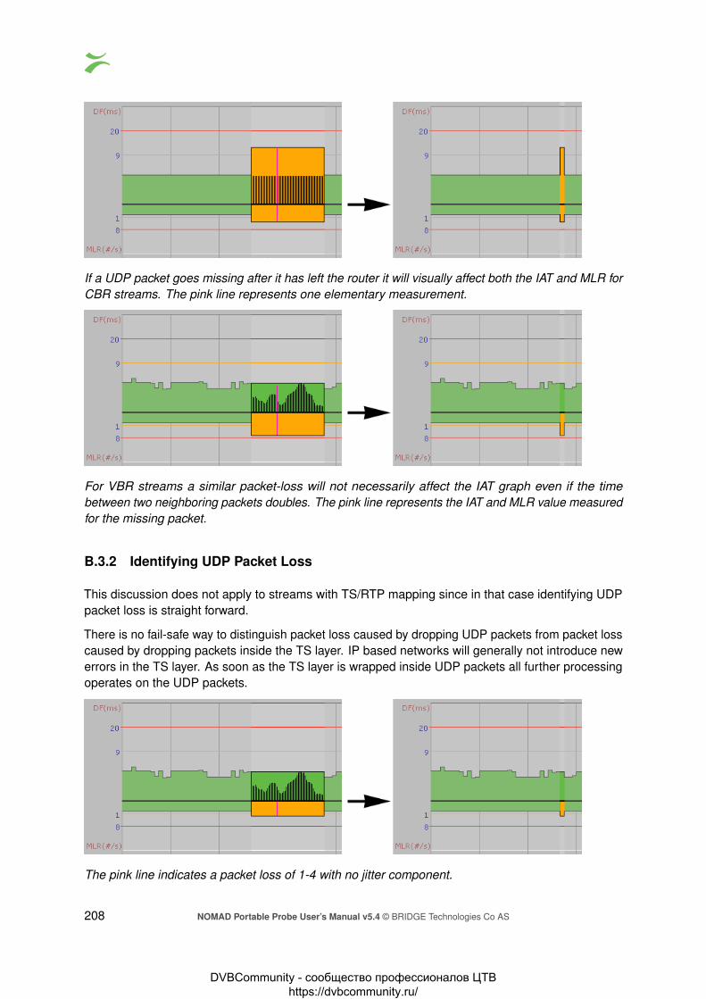
If a UDP packet goes missing after it has left the router it will visually affect both the IAT and MLR forCBR streams. The pink line represents one elementary measurement.
For VBR streams a similar packet-loss will not necessarily affect the IAT graph even if the timebetween two neighboring packets doubles. The pink line represents the IAT and MLR value measuredfor the missing packet.
B.3.2 Identifying UDP Packet Loss
This discussion does not apply to streams with TS/RTP mapping since in that case identifying UDPpacket loss is straight forward.
There is no fail-safe way to distinguish packet loss caused by dropping UDP packets from packet losscaused by dropping packets inside the TS layer. IP based networks will generally not introduce newerrors in the TS layer. As soon as the TS layer is wrapped inside UDP packets all further processingoperates on the UDP packets.
The pink line indicates a packet loss of 1-4 with no jitter component.
208 NOMAD Portable Probe User’s Manual v5.4 © BRIDGE Technologies Co AS
DVBCommunity - cообщество профессионалов ЦТВ https://dvbcommunity.ru/
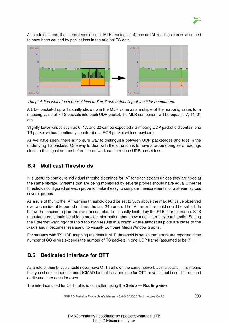
As a rule of thumb, the co-existence of small MLR readings (1-4) and no IAT readings can be assumedto have been caused by packet loss in the original TS data.
The pink line indicates a packet loss of 6 or 7 and a doubling of the jitter component.
A UDP packet-drop will usually show up in the MLR value as a multiple of the mapping value; for amapping value of 7 TS packets into each UDP packet, the MLR component will be equal to 7, 14, 21etc.
Slightly lower values such as 6, 13, and 20 can be expected if a missing UDP packet did contain oneTS packet without continuity counter (i.e. a PCR packet with no payload).
As we have seen, there is no sure way to distinguish between UDP packet-loss and loss in theunderlying TS packets. One way to deal with the situation is to have a probe doing zero readingsclose to the signal source before the network can introduce UDP packet loss.
B.4 Multicast Thresholds
It is useful to configure individual threshold settings for IAT for each stream unless they are fixed atthe same bit-rate. Streams that are being monitored by several probes should have equal Ethernetthresholds configured on each probe to make it easy to compare measurements for a stream acrossseveral probes.
As a rule of thumb the IAT warning threshold could be set to 50% above the max IAT value observedover a considerable period of time, the last 24h or so. The IAT error threshold could be set a littlebelow the maximum jitter the system can tolerate – usually limited by the STB jitter tolerance. STBmanufacturers should be able to provide information about how much jitter they can handle. Settingthe Ethernet warning-threshold too high results in a graph where almost all plots are close to thex-axis and it becomes less useful to visually compare MediaWindow graphs.
For streams with TS/UDP mapping the default MLR threshold is set so that errors are reported if thenumber of CC errors exceeds the number of TS packets in one UDP frame (assumed to be 7).
B.5 Dedicated interface for OTT
As a rule of thumb, you should never have OTT traffic on the same network as multicasts. This meansthat you should either use one NOMAD for multicast and one for OTT, or you should use different anddedicated interfaces for each.
The interface used for OTT traffic is controlled using the Setup — Routing view.
NOMAD Portable Probe User’s Manual v5.4 © BRIDGE Technologies Co AS 209
DVBCommunity - cообщество профессионалов ЦТВ https://dvbcommunity.ru/

B.6 OTT descrambling with Verimatrix
If you are using a Verimatrix VCAS 3.7 server to encrypt your OTT stream, you can get the NOMADto descramble the chunks. It will uses the same API to descramble the chunks, as the encoder orsegmenter uses to encrypt the chunks. To achieve this, the NOMAD need to be able to reach theVCAS server’s private encoder interface.
Since the NOMAD only uses a single interface for OTT, your network needs to be configured such asthe NOMAD can reach both the VCAS server and your origin server on the same interface.
B.7 OTT Bandwidth requirements
The recommended available bandwidth for full coverage OTT monitoring is equal to the sum of theprofile bitrates monitored plus an estimated overhead of 20 % for manifests and IP, TCP and HTTPheaders.
Note: The OTT engines will be using all available bandwidth on the interface in spikes whiledownloading the chunks, this is the main reason why it is not a good idea to mix multicasts on thesame interface, as it can cause packet drops which multicasts cannot handle.
210 NOMAD Portable Probe User’s Manual v5.4 © BRIDGE Technologies Co AS
DVBCommunity - cообщество профессионалов ЦТВ https://dvbcommunity.ru/

C Appendix: OTT Profile Health
C.1 OTT Profile Health Bar
The profile health bar displayed at channel level shows an overview of current status for individualchannel profiles. Different colors indicate status:
• Green: OK
• Yellow: Warning
• Orange: Error
• Red: Major
• Black: Fatal
All enabled alarms may affect the profile health bar, and alarm severities can be assigned to eachalarm in the Alarms — Alarm setup view.
C.2 OTT Profile Health Timeline
NOMAD Portable Probe User’s Manual v5.4 © BRIDGE Technologies Co AS 211
DVBCommunity - cообщество профессионалов ЦТВ https://dvbcommunity.ru/

The OTT profile health timeline shows information about channel bitrate and channel alarm status forthe last two hours, with a time resolution of one minute. Green parts of the timeline indicate profiledownload time versus chunk length. The graph is scaled so that 100% indicates a chunk downloadtime identical to chunk length (in seconds), chunk length being signaled in the profile manifest. Quickchunk download times therefore result in a ‘low’ green graph, as seen in the left hand part of the graphabove. When download times exceed the user defined profile bitrate warning and error thresholdsthe graph is colored yellow and orange respectively.
In addition to profile bitrate indication the graph displays profile status information related to non-bitrate alarms. Active profile alarms are represented in the graph as 100% bars, the color reflectingthe severity of the alarm. If several alarms are active within a one minute period the graph color willreflect the most severe alarm. Historical alarms can be examined in more detail by viewing the OTTalarm list.
212 NOMAD Portable Probe User’s Manual v5.4 © BRIDGE Technologies Co AS
DVBCommunity - cообщество профессионалов ЦТВ https://dvbcommunity.ru/

D Appendix: Software Maintenance
Purchasing yearly software maintenance enables future feature protection and guarantees access tothe latest software for the NOMAD. The latest version of the NOMAD software can be found in theEnd User area at http://www.bridgetech.tv/.
The software maintenance can be purchased for a three or five year period, typically initially purchasedtogether with the system itself, during which new major releases can be installed.
The current software maintenance period is displayed in the About — License view, see chapter6.15.2 for more details. For an overview of software maintenance periods for multiple units, pleaserefer to the Equipment view on the VBC Controller server.
For renewals, contact the local partner the system have been purchased from or Bridge Technologiesdirectly at: [email protected], with the title “se-maintenance”.
Use the Data — Software view to update the NOMAD software, please refer to chapter 6.14.2.
NOMAD Portable Probe User’s Manual v5.4 © BRIDGE Technologies Co AS 213
DVBCommunity - cообщество профессионалов ЦТВ https://dvbcommunity.ru/

E Appendix: Software Upload
The process of performing a software upload to the probe involves the following steps:
1. Obtain the software image.
2. Export and save the probe configuration.
3. Delete any existing probe stream recordings.
4. Transfer the image to the probe using the software upload functionality in the Data — Softwareview or by using ftp, and save the image to flash.
5. Wait while the software is being saved.
6. Verify the new image.
E.1 Obtain the software image
The image will have a .tea extension.
The version number, build date and possibly hardware version is usually also part of the file name.
For information on how to update a probe running hardware revisions 1–3, please refer to the User’sManual for the corresponding software release.
E.2 Export and save the probe configuration
Software upgrade should not alter the probe configuration, however for safety is is a good idea toexport the probe configuration (from the Data — Configuration view) and save it to a file. Pleaserefer to chapter 6.14.1.
E.3 Delete any existing probe stream recordings
If any stream recordings is stored on the probe, this may prevent software upgrade, as there mightnot be enough internal disk space available for the software image upload to be possible. Thereforedelete any recordings prior to software upload – this is done in the RDP — Control view.
214 NOMAD Portable Probe User’s Manual v5.4 © BRIDGE Technologies Co AS
DVBCommunity - cообщество профессионалов ЦТВ https://dvbcommunity.ru/

E.4 Transfer the image to the probe and save to flash
Using the software upload functionality in the Data view
From the Data — Software view select the software image file to be uploaded and click the Go!button. When the software has been successfully transferred to the probe click the Save flash buttonand confirm.
Progress bars are displayed to show the flash save status.
Note that the probe will reboot when the new software is successfully stored in flash, and the probewill be unresponsive until reboot has completed.
Using ftp and telnet/ssh
Step 1, alternative A: Using Windows Explorer
Open a Windows Explorer window. Click the address field and type ftp://10.0.20.101 (replace10.0.20.101 with the probe’s IP address) and hit Enter . When asked to log in, enter the User name
NOMAD Portable Probe User’s Manual v5.4 © BRIDGE Technologies Co AS 215
DVBCommunity - cообщество профессионалов ЦТВ https://dvbcommunity.ru/

admin and password elvis in all lower-case letters (this password can be changed in the Setup –Security view).
Then drag the software image onto the empty Windows Explorer window. It may be necessary toretype the string including user and password, as described above. When the file has been copiedonto the probe the Windows Explorer window may look as shown below.
Step 1, alternative B: Using a terminal based ftp client
In a terminal window type the following commands, replacing the software image name with therelevant one (the path to the folder in which the software is located should be specified):
ftp 10.0.20.101Connected to 10.0.20.101.220 bftpd 4.4 at 10.0.20.101 ready.503 USER expected.User (10.0.20.101:(none)): admin331 Password please.Password: elvis230 User logged in.ftp> binary200 Transfer type changed to BINARYftp> put vb330-5.2.0-10.tea...ftp> bye
Step 2: Initiate the save to flash using telnet or ssh
The image, which is now stored on the probe’s RAM-disk, needs to be saved to flash.
In a terminal window type these commands, replacing the IP address with the relevant one (note thatthe password will not be visible on the screen):
telnet 10.0.20.101gbprobe login: save_flashpassword: save_flash
216 NOMAD Portable Probe User’s Manual v5.4 © BRIDGE Technologies Co AS
DVBCommunity - cообщество профессионалов ЦТВ https://dvbcommunity.ru/

You can also use an Secure Shell (ssh) client, such as PuTTY1. Log in using the same user-nameand password as mentioned for the Telnet option above.
E.5 Wait while the software is being saved
This will take 6–15 minutes. The probe will then reboot automatically. The probe should state that thesoftware image has been saved successfully.
When using the alternate method do not disconnect the telnet or ssh session before the softwareupgrade is completed.
Note that if the probe is powered off while saving image to flash it will not be able to rebootnormally afterwards.
E.6 Verify the new image
Connect a browser towards the probe and verify the version and build time in the About — Releaseinfo view.
E.7 Software upload troubleshooting
If the upgrade is rejected, verify that the software version you are trying to upload is covered bysoftware maintenance. Refer to D Appendix: Software Maintenance for more details.
Probes that are unable to execute the user program (usually caused by interrupting the save-to-flashprocess described above) can still be upgraded. Contact your Bridge Technologies reseller for details.
If the web interface does not appear to work correctly straight after upgrading the probe it may bebecause the web browser is using files that are cached. Files may be cached for up to one hour inthe web browser. To fix the issue, clear the cache manually:
Google Chrome: Settings – History — Clear browsing data. . . — Cached images and files
Mozilla Firefox: Options — Advanced — Network — Cached Web Content — Clear Now
Microsoft Edge: Settings – Clear browsing data — Choose what to clear — Cached data and files
Microsoft Internet Explorer: Tools — Internet Options — General — Browsing history — Delete. . .— Temporary Internet files
Note that the probe configuration may be lost when downgrading to an older software version. In thiscase the saved configuration file may be useful.
1http://www.chiark.greenend.org.uk/~sgtatham/putty/
NOMAD Portable Probe User’s Manual v5.4 © BRIDGE Technologies Co AS 217
DVBCommunity - cообщество профессионалов ЦТВ https://dvbcommunity.ru/

F Appendix: Restoring NOMAD factorydefaults
It is possible to reset the probe to factory settings, erasing all information about the probe configurationand alarm history.
Please note that after factory reset, the management port will be assigned a default IP address of10.0.30.220, with a subnet mask of 255.255.255.0. This is different from the default IP addresswhen the unit is shipped from factory, which is 10.0.20.101 with a subnet mask of 255.255.0.0. Itwill be necessary to manually set the IP address using one of the methods described in section 4.4.Generally this will have to be done on-site.
Also note that the unit license key should be noted and stored before the factory reset is performed,as it might be reset by the factory reset process. The license key is found in the About — Licenseview of the probe, please refer to section 6.15.2. The license key is also printed during the factoryreset process.
To perform a factory reset of the probe, connect to it using the USB cable using the method describedin section 4.4.3. Instead of logging in as admin, log in with the user name reset_factory and thepassword reset_factory. This will start the factory reset process. Do not close the terminal windowduring the reset process. It is also possible to connect using telnet or ssh, if the corresponding settinghas been enabled in the Setup — Security view.
After factory reset, set the management IP address. When regular web connection is established,verify that the license key is present in the About — License view of the probe GUI. If it is not, typeor paste it in the license key field and click the Submit button.
218 NOMAD Portable Probe User’s Manual v5.4 © BRIDGE Technologies Co AS
DVBCommunity - cообщество профессионалов ЦТВ https://dvbcommunity.ru/